EP3834735A1 - Ultrasound diagnosis apparatus, method for displaying ultrasound image, and computer program product - Google Patents
Ultrasound diagnosis apparatus, method for displaying ultrasound image, and computer program product Download PDFInfo
- Publication number
- EP3834735A1 EP3834735A1 EP19846190.7A EP19846190A EP3834735A1 EP 3834735 A1 EP3834735 A1 EP 3834735A1 EP 19846190 A EP19846190 A EP 19846190A EP 3834735 A1 EP3834735 A1 EP 3834735A1
- Authority
- EP
- European Patent Office
- Prior art keywords
- data
- ultrasonic
- microcalcified tissue
- image
- microcalcified
- Prior art date
- Legal status (The legal status is an assumption and is not a legal conclusion. Google has not performed a legal analysis and makes no representation as to the accuracy of the status listed.)
- Pending
Links
Images



Classifications
-
- A—HUMAN NECESSITIES
- A61—MEDICAL OR VETERINARY SCIENCE; HYGIENE
- A61B—DIAGNOSIS; SURGERY; IDENTIFICATION
- A61B8/00—Diagnosis using ultrasonic, sonic or infrasonic waves
- A61B8/52—Devices using data or image processing specially adapted for diagnosis using ultrasonic, sonic or infrasonic waves
- A61B8/5215—Devices using data or image processing specially adapted for diagnosis using ultrasonic, sonic or infrasonic waves involving processing of medical diagnostic data
- A61B8/5238—Devices using data or image processing specially adapted for diagnosis using ultrasonic, sonic or infrasonic waves involving processing of medical diagnostic data for combining image data of patient, e.g. merging several images from different acquisition modes into one image
- A61B8/5246—Devices using data or image processing specially adapted for diagnosis using ultrasonic, sonic or infrasonic waves involving processing of medical diagnostic data for combining image data of patient, e.g. merging several images from different acquisition modes into one image combining images from the same or different imaging techniques, e.g. color Doppler and B-mode
-
- A—HUMAN NECESSITIES
- A61—MEDICAL OR VETERINARY SCIENCE; HYGIENE
- A61B—DIAGNOSIS; SURGERY; IDENTIFICATION
- A61B8/00—Diagnosis using ultrasonic, sonic or infrasonic waves
- A61B8/08—Clinical applications
- A61B8/0858—Clinical applications involving measuring tissue layers, e.g. skin, interfaces
-
- A—HUMAN NECESSITIES
- A61—MEDICAL OR VETERINARY SCIENCE; HYGIENE
- A61B—DIAGNOSIS; SURGERY; IDENTIFICATION
- A61B8/00—Diagnosis using ultrasonic, sonic or infrasonic waves
- A61B8/08—Clinical applications
- A61B8/0825—Clinical applications for diagnosis of the breast, e.g. mammography
-
- A—HUMAN NECESSITIES
- A61—MEDICAL OR VETERINARY SCIENCE; HYGIENE
- A61B—DIAGNOSIS; SURGERY; IDENTIFICATION
- A61B8/00—Diagnosis using ultrasonic, sonic or infrasonic waves
- A61B8/08—Clinical applications
-
- A—HUMAN NECESSITIES
- A61—MEDICAL OR VETERINARY SCIENCE; HYGIENE
- A61B—DIAGNOSIS; SURGERY; IDENTIFICATION
- A61B8/00—Diagnosis using ultrasonic, sonic or infrasonic waves
- A61B8/08—Clinical applications
- A61B8/0833—Clinical applications involving detecting or locating foreign bodies or organic structures
- A61B8/085—Clinical applications involving detecting or locating foreign bodies or organic structures for locating body or organic structures, e.g. tumours, calculi, blood vessels, nodules
-
- A—HUMAN NECESSITIES
- A61—MEDICAL OR VETERINARY SCIENCE; HYGIENE
- A61B—DIAGNOSIS; SURGERY; IDENTIFICATION
- A61B8/00—Diagnosis using ultrasonic, sonic or infrasonic waves
- A61B8/46—Ultrasonic, sonic or infrasonic diagnostic devices with special arrangements for interfacing with the operator or the patient
- A61B8/461—Displaying means of special interest
-
- A—HUMAN NECESSITIES
- A61—MEDICAL OR VETERINARY SCIENCE; HYGIENE
- A61B—DIAGNOSIS; SURGERY; IDENTIFICATION
- A61B8/00—Diagnosis using ultrasonic, sonic or infrasonic waves
- A61B8/48—Diagnostic techniques
- A61B8/483—Diagnostic techniques involving the acquisition of a 3D volume of data
-
- A—HUMAN NECESSITIES
- A61—MEDICAL OR VETERINARY SCIENCE; HYGIENE
- A61B—DIAGNOSIS; SURGERY; IDENTIFICATION
- A61B8/00—Diagnosis using ultrasonic, sonic or infrasonic waves
- A61B8/52—Devices using data or image processing specially adapted for diagnosis using ultrasonic, sonic or infrasonic waves
- A61B8/5207—Devices using data or image processing specially adapted for diagnosis using ultrasonic, sonic or infrasonic waves involving processing of raw data to produce diagnostic data, e.g. for generating an image
-
- A—HUMAN NECESSITIES
- A61—MEDICAL OR VETERINARY SCIENCE; HYGIENE
- A61B—DIAGNOSIS; SURGERY; IDENTIFICATION
- A61B8/00—Diagnosis using ultrasonic, sonic or infrasonic waves
- A61B8/52—Devices using data or image processing specially adapted for diagnosis using ultrasonic, sonic or infrasonic waves
- A61B8/5215—Devices using data or image processing specially adapted for diagnosis using ultrasonic, sonic or infrasonic waves involving processing of medical diagnostic data
- A61B8/5223—Devices using data or image processing specially adapted for diagnosis using ultrasonic, sonic or infrasonic waves involving processing of medical diagnostic data for extracting a diagnostic or physiological parameter from medical diagnostic data
-
- G—PHYSICS
- G01—MEASURING; TESTING
- G01S—RADIO DIRECTION-FINDING; RADIO NAVIGATION; DETERMINING DISTANCE OR VELOCITY BY USE OF RADIO WAVES; LOCATING OR PRESENCE-DETECTING BY USE OF THE REFLECTION OR RERADIATION OF RADIO WAVES; ANALOGOUS ARRANGEMENTS USING OTHER WAVES
- G01S15/00—Systems using the reflection or reradiation of acoustic waves, e.g. sonar systems
- G01S15/88—Sonar systems specially adapted for specific applications
- G01S15/89—Sonar systems specially adapted for specific applications for mapping or imaging
- G01S15/8906—Short-range imaging systems; Acoustic microscope systems using pulse-echo techniques
- G01S15/895—Short-range imaging systems; Acoustic microscope systems using pulse-echo techniques characterised by the transmitted frequency spectrum
- G01S15/8952—Short-range imaging systems; Acoustic microscope systems using pulse-echo techniques characterised by the transmitted frequency spectrum using discrete, multiple frequencies
-
- G—PHYSICS
- G01—MEASURING; TESTING
- G01S—RADIO DIRECTION-FINDING; RADIO NAVIGATION; DETERMINING DISTANCE OR VELOCITY BY USE OF RADIO WAVES; LOCATING OR PRESENCE-DETECTING BY USE OF THE REFLECTION OR RERADIATION OF RADIO WAVES; ANALOGOUS ARRANGEMENTS USING OTHER WAVES
- G01S7/00—Details of systems according to groups G01S13/00, G01S15/00, G01S17/00
- G01S7/52—Details of systems according to groups G01S13/00, G01S15/00, G01S17/00 of systems according to group G01S15/00
- G01S7/52017—Details of systems according to groups G01S13/00, G01S15/00, G01S17/00 of systems according to group G01S15/00 particularly adapted to short-range imaging
- G01S7/52019—Details of transmitters
- G01S7/5202—Details of transmitters for pulse systems
-
- G—PHYSICS
- G01—MEASURING; TESTING
- G01S—RADIO DIRECTION-FINDING; RADIO NAVIGATION; DETERMINING DISTANCE OR VELOCITY BY USE OF RADIO WAVES; LOCATING OR PRESENCE-DETECTING BY USE OF THE REFLECTION OR RERADIATION OF RADIO WAVES; ANALOGOUS ARRANGEMENTS USING OTHER WAVES
- G01S7/00—Details of systems according to groups G01S13/00, G01S15/00, G01S17/00
- G01S7/52—Details of systems according to groups G01S13/00, G01S15/00, G01S17/00 of systems according to group G01S15/00
- G01S7/52017—Details of systems according to groups G01S13/00, G01S15/00, G01S17/00 of systems according to group G01S15/00 particularly adapted to short-range imaging
- G01S7/52023—Details of receivers
- G01S7/52036—Details of receivers using analysis of echo signal for target characterisation
Definitions
- the ultrasound diagnosis apparatus has advantages in that the ultrasound diagnosis apparatus is harmless to the human body and may observe the internal structure and characteristics of the human body in a non-invasive manner.
- the ultrasound diagnosis apparatus may provide various types of clinical information (such as tissue shape, elasticity, blood flow rate, and the like).
- the ultrasound diagnosis apparatus may be used for observing microcalcifications or for real-time monitoring for a biopsy of the microcalcified tissue.
- a breast ultrasound or musculoskeletal ultrasound may be used.
- an ultrasound diagnosis apparatus including: an ultrasonic transceiver configured to acquire first data by allowing a probe to transmit a first ultrasonic pulse to an object and receive an echo signal reflected from the object and configured to acquire second data by allowing the probe to repeatedly perform, a plurality of times at predetermined time intervals, an operation of transmitting a second ultrasonic pulse different from the first ultrasonic pulse to the object and receiving an echo signal reflected from the object; a controller configured to detect microcalcified tissue in the object by analyzing the second data; and a display unit configured to display an ultrasonic image generated based on the first data and an image representing the detected microcalcified tissue.
- Still another aspect of the present invention provides a computer program product including a storage medium configured to store computer program code for performing the above-described method of displaying an ultrasonic image.
- an "image” may include a medical image obtained by a medical imaging apparatus such as a magnetic resonance imaging (MRI) device, a computed tomography (CT) device, an ultrasound imaging device, and an X-ray imaging device.
- MRI magnetic resonance imaging
- CT computed tomography
- ultrasound imaging device an ultrasound imaging device
- X-ray imaging device an X-ray imaging device
- the controller 120 controls a reception unit 115 to convert a reception signal received from the probe 20 in an analog-to-digital conversion manner and to sum the digitally converted reception signal in consideration of the positions and focal points of the plurality of transducers, thereby generating ultrasonic data.
- the image processing unit 130 generates an ultrasonic image using the ultrasonic data generated by the ultrasonic reception unit 115.
- the ultrasound diagnosis apparatus 100 may include the communication unit 160 and may be connected, through the communication unit 160, to an external device (for example, a server, a medical device, a portable device (a smart phone, a tablet PC, a wearable device, and the like)).
- an external device for example, a server, a medical device, a portable device (a smart phone, a tablet PC, a wearable device, and the like)).
- FIGS. 2A to 2C are views illustrating ultrasound diagnosis apparatuses according to an embodiment.
- ultrasound diagnosis apparatuses 100a and 100b may each include a main display unit 121 and a sub display unit 122.
- One of the main display unit 121 and the sub display unit 122 may be implemented as a touch screen.
- the main display unit 121 and the sub display unit 122 may display the ultrasonic image or various pieces of information processed by the ultrasound diagnosis apparatuses 100a and 100b.
- the main display unit 121 and the sub display unit 122 may be implemented as a touch screen and provide a graphical user interface (GUI) to receive data for controlling the ultrasound diagnosis apparatuses 100a and 100b from a user.
- GUI graphical user interface
- the main display unit 121 may display the ultrasonic image
- the sub display unit 122 may display a control panel for controlling the ultrasonic image in the form of the GUI.
- the sub display unit 122 may receive data for controlling the displaying of the image through the control panel displayed in the form of the GUI.
- the ultrasound diagnosis apparatuses 100a and 100b may control, using input control data, the displaying of the ultrasonic image displayed on the main display unit 121.
- the ultrasound diagnosis apparatus 100c may be implemented as a portable type.
- Examples of a portable ultrasound diagnosis apparatus 100c may include a smart phone, a laptop computer, a PDA, a tablet PC, and the like including a probe and an application, but the present invention is not limited thereto.
- the ultrasound diagnosis apparatus may use a method of imaging the microcalcification using an image post-processing algorithm such as imaging the microcalcification using various channel data-based beamforming techniques or performing feature enhancement of only hyperechoic components.
- the ultrasonic transceiver 310 transmits an ultrasonic pulse to the object through the probe 20 based on the control signal applied from the controller 330, receives a radio frequency (RF) signal reflected from the object through the probe 20, and outputs the RF signal to the controller 330.
- RF radio frequency
- the ultrasonic transceiver 310 may acquire first data by allowing the probe 20 to transmit a first ultrasonic pulse to the object and receive an echo signal reflected from the object.
- the first ultrasonic pulse may be a pulse designed to acquire a B mode image.
- the second ultrasonic pulse may be a pulse designed based on characteristics of the microcalcified tissue.
- the second ultrasonic pulse may be a pulse having a sequence in which the magnitude of a waveform, the signal of a phase, a period, and the like are predefined to detect the microcalcification.
- the second ultrasonic pulse may be an asymmetric pulse in which a negative pressure component is dominant as compared to a positive pressure component and may be designed to have a wavelength longer than that of the first ultrasonic pulse.
- the controller 330 may calculate, based on the second data, a variance of the phase change over time of the echo signal reflected from each region of the object and detect a region in which the variance of the phase change is larger than or equal to a predetermined value as the microcalcified tissue in the object.
- the display unit 340 may independently display the ultrasonic image and the image representing the microcalcification in different regions. Further, the display unit 340 may display one image by fusing the B mode image of the cross-section of the object and the image representing the microcalcification. Further, the display unit 340 may display a region corresponding to the detected microcalcified tissue on the ultrasonic image that is the B mode image of the cross-section of the object.
- FIG. 4 is a view illustrating a controller 320 of the ultrasound diagnosis apparatus 300 according to the embodiment.
- the pulse generation unit 410 may generate an ultrasonic pulse designed to acquire a Doppler image representing the motion of the object as well as a gray-scale ultrasonic image obtained by scanning the object according to an A mode (amplitude mode), a B mode (brightness mode), and an M mode (motion mode).
- a mode amplitude mode
- B mode brightness mode
- M mode motion mode
- the pulse generation unit 410 may generate a first ultrasonic pulse predesigned to acquire the B mode image. Further, the pulse generation unit 410 according to the embodiment may generate a second ultrasonic pulse predesigned to detect the microcalcification. The pulse generation unit 410 may generate a second ultrasonic pulse in which transmission parameters such as a sign, a magnitude, a phase, and a period of a waveform are determined in advance based on the characteristics of the microcalcification.
- the ultrasonic pulse optimized for detection of the microcalcification may be designed based on experimental results of FIGS. 6 and 7 .
- a graph 600 of FIG. 6 represents an average value of microcalcification signals received from the object when an ultrasonic pulse having a waveform illustrated in FIG. 5 is applied to the object including a phantom simulating breast microcalcification.
- a graph 700 of FIG. 7 represents a change in the average value of the microcalcification signals received from the object when the negative pressure of the ultrasonic pulse having a dominant negative pressure illustrated in the graph 520 of FIG. 5 is increased.
- a graph 710 of FIG. 7 represents a change in the average value of the microcalcification signals received from the object when the negative pressure of the ultrasonic pulse having a low frequency and a dominant negative pressure is increased.
- a graph 720 of FIG. 7 represents a change in the average value of the microcalcification signals received from the object when the negative pressure of the ultrasonic pulse having a general frequency and a dominant negative pressure is increased.
- the pulse generation unit 410 may preferably generate, as the second ultrasonic pulse, an ultrasonic pulse having a wavelength that is longer than a predetermined value. Further, according to the experimental result illustrated in FIG. 7 , it may be seen that as the negative pressure of the ultrasonic pulse increases, the average value of the microcalcification signals received from the object increases.
- the ultrasound diagnosis apparatus 300 may acquire the second data by repeatedly performing, a predefined number of times at predefined time intervals, an operation of transmitting the second ultrasonic pulse to the object 10 through the probe 20 and receiving the echo signal.
- the second data may include a plurality of pieces of image data acquired with respect to the cross-section of the object at a predetermined period, and each piece of image data may include spatial information on the cross-section of the object.
- the spatiotemporal data acquisition unit 420 may reconstruct three-dimensional data 801 including the information on the axial depth, the lateral width, and time by arranging, on a time axis, the plurality of pieces of image data included in the second data. Since the data acquired by the spatiotemporal data acquisition unit 420 includes both temporal information and spatial information, the data may be described as the spatiotemporal data.
- the microcalcification detection unit 440 may independently detect the spatiotemporal data obtained from the spatiotemporal data acquisition unit 420 by distinguishing general tissue and the microcalcification from each other through spatiotemporal characteristic analysis. For example, the microcalcification detection unit 440 may independently detect the microcalcification signal by performing singular value decomposition on the spatiotemporal data. Further, the microcalcification detection unit 440 may perform independent microcalcification signal detection based on a power, an average frequency, a phase change, or the like of the microcalcification signal using an autocorrelation function. For example, the microcalcification detection unit 440 may use a microcalcification power estimation value based on the autocorrelation function.
- the microcalcification detection unit 440 may separate and detect the microcalcification signal from the spatiotemporal data based on such phase change characteristics of the microcalcification.
- the microcalcification detection unit 440 may determine the microcalcified tissue when the variance of the phase change is larger than or equal to a predetermined value.
- FIG. 10 is a view for describing a method of detecting microcalcified tissue by the microcalcification detection unit 440 according to the embodiment.
- the microcalcification detection unit 440 may separate and detect an independent microcalcification signal by analyzing spatiotemporal signal characteristics based on a result of applying the spatiotemporal signal characteristic analysis function. For example, the microcalcification detection unit 440 may detect, as the microcalcification signal, a signal in a region having a wide distribution of the phase change over time.
- FIGS. 11 and 12 illustrate screens displayed on the ultrasound diagnosis apparatus according to the embodiment.
- the display unit 340 may independently display an ultrasonic image 1110 generated by the controller 320 and an image 1130 representing the microcalcification in different regions on a screen 1100.
- a region 1113 on the ultrasonic image 1110 is a region in which the microcalcification is concentrated in the object, and according to the diagnosis apparatus 300 according to the embodiment, the image 1130 on which only the microcalcification region is independently displayed may be generated and displayed. Similar to the ultrasonic image 1110, it is identified that the microcalcifications are concentrated in a region 1133 on the image 1130.
- the display unit 340 may further display a color bar representing a plurality of colors corresponding to the values representing the characteristics of the microcalcified tissue.
- the display unit 340 may select a color from the color bar based on a value representing the characteristics of the detected microcalcified tissue and may display the selected color in a region corresponding to the detected microcalcified tissue.
- the embodiments are not limited thereto, and various methods for representing the characteristics of the microcalcification in addition to the form of the color bar may be used.
- FIG. 12 illustrates an example of a screen on which the variance of the phase is displayed as a characteristic of the microcalcified tissue.
- the display unit 340 may display, on the ultrasonic image, an image 1210 in which regions 1211, 1212, 1213, and 1214 corresponding to the microcalcification are displayed.
- the regions 1211, 1212, 1213, and 1214 corresponding to the microcalcification may be displayed in predetermined colors on the ultrasonic image.
- the ultrasonic diagnosis apparatus 300 may acquire the second data by repeatedly performing, a plurality of times at predetermined time intervals, an operation of transmitting the second ultrasonic pulse different from the first ultrasonic pulse to the object and receiving the echo signal reflected from the object.
- the second ultrasonic pulse may be a pulse designed based on characteristics of the microcalcified tissue.
- the second ultrasonic pulse may be an asymmetric pulse in which a negative pressure component is dominant as compared to a positive pressure component and may have a wavelength longer than that of the first ultrasonic pulse.
- the ultrasound diagnosis apparatus 300 may detect the microcalcified tissue in the object by analyzing the second data.
- the ultrasound diagnosis apparatus 300 may reconstruct the second data acquired in operation S1320 into the three-dimensional data including the information on the axial depth, the lateral width, and time.
- the ultrasound diagnosis apparatus 300 may extract the microcalcified tissue by analyzing the three-dimensional data.
- the ultrasound diagnosis apparatus 300 may calculate, based on the second data, the variance of the phase change over time of the echo signal reflected from each region of the object and detect a region in which the variance of the phase change is larger than or equal to a predetermined value as the microcalcified tissue in the object.
- the ultrasound diagnosis apparatus 300 may display the ultrasonic image generated based on the first data and the image representing the detected microcalcified tissue.
- the computer-readable storage medium may be provided in the form of a non-transitory storage medium.
- non-transitory means that the storage medium does not include a signal and is tangible but does not distinguish that data is semi-permanently or temporarily stored in the storage medium.
- the third device may execute the computer program product to control the terminal communicatively connected to the third device to perform the method according to the disclosed embodiments.
- the third device may remotely control the ultrasound diagnosis apparatus to irradiate the object with the ultrasonic signal and generate an image of a part inside the object based on information on a signal reflected from the object.
Landscapes
- Health & Medical Sciences (AREA)
- Life Sciences & Earth Sciences (AREA)
- Engineering & Computer Science (AREA)
- Physics & Mathematics (AREA)
- Surgery (AREA)
- Heart & Thoracic Surgery (AREA)
- Veterinary Medicine (AREA)
- Public Health (AREA)
- General Health & Medical Sciences (AREA)
- Animal Behavior & Ethology (AREA)
- Biophysics (AREA)
- Nuclear Medicine, Radiotherapy & Molecular Imaging (AREA)
- Pathology (AREA)
- Radiology & Medical Imaging (AREA)
- Biomedical Technology (AREA)
- Molecular Biology (AREA)
- Medical Informatics (AREA)
- Radar, Positioning & Navigation (AREA)
- Remote Sensing (AREA)
- Computer Vision & Pattern Recognition (AREA)
- Computer Networks & Wireless Communication (AREA)
- General Physics & Mathematics (AREA)
- Acoustics & Sound (AREA)
- Vascular Medicine (AREA)
- Physiology (AREA)
- Ultra Sonic Daignosis Equipment (AREA)
Abstract
Description
- The present invention relates to an ultrasound diagnosis apparatus, a method of displaying an ultrasonic image, and a computer program product. Further, the disclosed embodiments may relate to a method of generating and displaying an image representing microcalcified tissue in an ultrasound diagnosis apparatus.
- Microcalcifications generated according to the accumulation of calcium in the human body cause disorders in organs or cardiovascular functions in the human body and manifest various diseases. In particular, it is known that microcalcified tissue present in the breast is highly likely to metastasize to malignant tumors, and thus a technique capable of detecting microcalcified tissue at an early stage is required to diagnose breast cancer early.
- In microcalcification detection techniques according to the related art, X-ray images may be mainly used in consideration of the fact that calcareous materials absorb relatively little X-rays. However, this technique has disadvantages in that microcalcified tissue may not be detected in real time, user accessibility is degraded, and there is a potential risk (blood flow apoptosis, cancer expression, and DNA mutation) due to exposure of patients to radiation. Further, in clinically reading microcalcified tissue, evaluation of objectivity and standardized criterion are insufficient.
- Meanwhile, an ultrasound diagnosis apparatus irradiates an object with an ultrasound signal generated from a transducer of a probe and receives information on the signal reflected from the object to obtain at least one image of a part (for example, soft tissue or blood flow) inside the object.
- The ultrasound diagnosis apparatus has advantages in that the ultrasound diagnosis apparatus is harmless to the human body and may observe the internal structure and characteristics of the human body in a non-invasive manner. The ultrasound diagnosis apparatus may provide various types of clinical information (such as tissue shape, elasticity, blood flow rate, and the like). In particular, the ultrasound diagnosis apparatus may be used for observing microcalcifications or for real-time monitoring for a biopsy of the microcalcified tissue. In this case, a breast ultrasound or musculoskeletal ultrasound may be used.
- Disclosed embodiments are for enabling an ultrasound diagnosis apparatus to display an image representing microcalcified tissue.
- One aspect of the present invention provides a method of displaying an ultrasonic image, the method including: acquiring first data by transmitting a first ultrasonic pulse to an object and by receiving an echo signal reflected from the object; acquiring second data by repeatedly performing, a plurality of times at predetermined time intervals, an operation of transmitting a second ultrasonic pulse different from the first ultrasonic pulse to the object and receiving an echo signal reflected from the object; detecting microcalcified tissue in the object by analyzing the second data; and displaying an ultrasonic image generated based on the first data and an image representing the detected microcalcified tissue.
- Another aspect of the present invention provides an ultrasound diagnosis apparatus including: an ultrasonic transceiver configured to acquire first data by allowing a probe to transmit a first ultrasonic pulse to an object and receive an echo signal reflected from the object and configured to acquire second data by allowing the probe to repeatedly perform, a plurality of times at predetermined time intervals, an operation of transmitting a second ultrasonic pulse different from the first ultrasonic pulse to the object and receiving an echo signal reflected from the object; a controller configured to detect microcalcified tissue in the object by analyzing the second data; and a display unit configured to display an ultrasonic image generated based on the first data and an image representing the detected microcalcified tissue.
- Still another aspect of the present invention provides a computer program product including a storage medium configured to store computer program code for performing the above-described method of displaying an ultrasonic image.
- According to the disclosed embodiments, an ultrasound diagnosis apparatus can accurately detect microcalcified tissue and can independently display only a microcalcification image or display an image representing a microcalcification by fusing the microcalcification image with an ultrasonic B mode image.
-
-
FIG. 1 is a block diagram illustrating a configuration of an ultrasound diagnosis apparatus according to an embodiment. -
FIGS. 2A to 2C are views illustrating ultrasound diagnosis apparatuses according to an embodiment. -
FIG. 3 is a view illustrating a structure of an ultrasound diagnosis apparatus according to an embodiment. -
FIG. 4 is a view illustrating a structure of a controller of the ultrasound diagnosis apparatus according to the embodiment. -
FIGS. 5 to 7 are views for describing a pulse transmitted to detect a microcalcification according to the embodiment. -
FIG. 8 is a view for describing spatiotemporal data generated according to the embodiment. -
FIG. 9 is a view for describing characteristics of calcified tissue. -
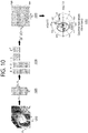
FIG. 10 is a view for describing a method of detecting microcalcified tissue according to the embodiment. -
FIGS. 11 and12 illustrate screens displayed on the ultrasound diagnosis apparatus according to the embodiment. -
FIG. 13 is a flowchart illustrating a method of displaying an ultrasonic image according to the embodiment. - One aspect of the present invention provides a method of displaying an ultrasonic image, the method including: acquiring first data by transmitting a first ultrasonic pulse to an object and receiving an echo signal reflected from the object; acquiring second data by repeatedly performing, a plurality of times at predetermined time intervals, an operation of transmitting a second ultrasonic pulse different from the first ultrasonic pulse to the object and receiving an echo signal reflected from the object; detecting microcalcified tissue in the object by analyzing the second data; and displaying an ultrasonic image generated based on the first data and an image representing the detected microcalcified tissue.
- Another aspect of the present invention provides an ultrasound diagnosis apparatus including: an ultrasonic transceiver configured to acquire first data by allowing a probe to transmit a first ultrasonic pulse to an object and receive an echo signal reflected from the object and configured to acquire second data by allowing the probe to repeatedly perform, a plurality of times at predetermined time intervals, an operation of transmitting a second ultrasonic pulse different from the first ultrasonic pulse to the object and receiving an echo signal reflected from the object; a controller configured to detect microcalcified tissue in the object by analyzing the second data; and a display unit configured to display an ultrasonic image generated based on the first data and an image representing the detected microcalcified tissue.
- Still another aspect of the present invention provides a computer program product including a storage medium configured to store computer program code for performing the above-described method of displaying an ultrasonic image.
- The present specification describes the principles of the present invention and discloses embodiments such that the scope of the present invention may be clarified and those skilled in the art to which the present invention pertains may implement the present invention. The disclosed embodiments may be implemented in various forms.
- Throughout the specification, the same reference numerals refer to the same components. The present specification does not describe all components of the embodiments, and general contents or duplicated contents between the embodiments in the technical field to which the present invention pertains will be omitted. Terms such as "part" or "portion" used in the specification may be implemented as software or hardware, and according to the embodiments, a plurality of "parts" or "portions" may be implemented as one unit or element, and one "part" or "portion" may include a plurality of units or elements. Hereinafter, the operating principles and embodiments of the present invention will be described with reference to the accompanying drawings.
- In the present specification, an "image" may include a medical image obtained by a medical imaging apparatus such as a magnetic resonance imaging (MRI) device, a computed tomography (CT) device, an ultrasound imaging device, and an X-ray imaging device.
- In the present specification, an "object" is to be photographed and may include a person, an animal, or a part thereof. For example, the object may include a part (organ) of a human body, a phantom, or the like.
- Throughout the specification, an "ultrasonic image" means an image of the object, which is processed based on an ultrasonic signal transmitted to the object and reflected from the object.
- Hereinafter, the embodiments will be described in detail with reference to the accompanying drawings.
-
FIG. 1 is a block diagram illustrating a configuration of anultrasound diagnosis apparatus 100 according to an embodiment. Theultrasound diagnosis apparatus 100 may include aprobe 20, anultrasonic transceiver 110, acontroller 120, animage processing unit 130, adisplay unit 140, astorage unit 150, acommunication unit 160, and aninput unit 170. - The
ultrasound diagnosis apparatus 100 may be implemented as a portable type as well as a cart type. Examples of a portable ultrasound diagnosis apparatus may include a smart phone, a laptop computer, a personal digital assistant (PDA), a tablet personal computer (PC), and the like including a probe and an application, but the present invention is not limited thereto. - The
probe 20 may include a plurality of transducers. The plurality of transducers may transmit ultrasonic signals to anobject 10 according to a transmission signal applied from atransmission unit 113. The plurality of transducers may receive ultrasonic signals reflected from theobject 10 to form a reception signal. Further, theprobe 20 may be implemented integrally with theultrasound diagnosis apparatus 100 or may be implemented as a separate type in which theprobe 20 is connected to theultrasound diagnosis apparatus 100 in a wired or wireless manner. Further, theultrasound diagnosis apparatus 100 may include one ormore probes 20 according to an implementation form. - The
controller 120 controls thetransmission unit 113 to form a transmission signal to be applied to each of the plurality of transducers in consideration of the positions and focal points of the plurality of transducers included in theprobe 20. - The
controller 120 controls areception unit 115 to convert a reception signal received from theprobe 20 in an analog-to-digital conversion manner and to sum the digitally converted reception signal in consideration of the positions and focal points of the plurality of transducers, thereby generating ultrasonic data. - The
image processing unit 130 generates an ultrasonic image using the ultrasonic data generated by theultrasonic reception unit 115. - The
display unit 140 may display the generated ultrasonic image and various pieces of information processed by theultrasound diagnosis apparatus 100. Theultrasound diagnosis apparatus 100 may include one ormore display units 140 according to an implementation form. Further, thedisplay unit 140 may be implemented as a touch screen in combination with a touch panel. - The
controller 120 may control the overall operation of theultrasound diagnosis apparatus 100 and a signal flow between internal components of theultrasound diagnosis apparatus 100. Thecontroller 120 may include a memory that stores a program or data for performing a function of theultrasound diagnosis apparatus 100 and a processor that processes the program or data. Further, thecontroller 120 may control the operation of theultrasonic diagnosis device 100 by receiving a control signal from theinput unit 170 or an external device. - The
ultrasound diagnosis apparatus 100 may include thecommunication unit 160 and may be connected, through thecommunication unit 160, to an external device (for example, a server, a medical device, a portable device (a smart phone, a tablet PC, a wearable device, and the like)). - The
communication unit 160 may include one or more components enabling communication with the external device and may include, for example, at least one of a short-range communication module, a wired communication module, and a wireless communication module. - The
communication unit 160 may transmit and receive the control signal to and from the external device. - The
storage unit 150 may store various types of data or programs for driving and controlling theultrasound diagnosis apparatus 100, input/output ultrasonic data, acquired ultrasonic images, and the like. - The
input unit 170 may receive a user's input for controlling theultrasound diagnosis apparatus 100. Although the user's input may include, for example, input obtained by manipulating a button, a keypad, a mouse, a trackball, a jog switch, a knob, and the like, input obtained by touching a touch panel or a touch screen, voice input, motion input, biometric information input (for example, iris recognition, fingerprint recognition, and the like), and the like, the present invention is not limited thereto. - Examples of the
ultrasound diagnosis apparatus 100 according to the embodiment will be described throughFIGS. 2A to 2C . -
FIGS. 2A to 2C are views illustrating ultrasound diagnosis apparatuses according to an embodiment. - Referring to
FIGS. 2A and 2B ,ultrasound diagnosis apparatuses main display unit 121 and asub display unit 122. One of themain display unit 121 and thesub display unit 122 may be implemented as a touch screen. Themain display unit 121 and thesub display unit 122 may display the ultrasonic image or various pieces of information processed by theultrasound diagnosis apparatuses main display unit 121 and thesub display unit 122 may be implemented as a touch screen and provide a graphical user interface (GUI) to receive data for controlling theultrasound diagnosis apparatuses main display unit 121 may display the ultrasonic image, and thesub display unit 122 may display a control panel for controlling the ultrasonic image in the form of the GUI. Thesub display unit 122 may receive data for controlling the displaying of the image through the control panel displayed in the form of the GUI. Theultrasound diagnosis apparatuses main display unit 121. - Referring to
FIG. 2B , theultrasound diagnosis apparatus 100b may further include acontrol panel 165 in addition to themain display unit 121 and thesub display unit 122. Thecontrol panel 165 may include a button, a trackball, a jog switch, a knob, and the like, and may receive data for controlling theultrasound diagnosis apparatus 100b from the user. For example, thecontrol panel 165 may include a time gain compensation (TGC)button 171, afreeze button 172, and the like. TheTGC button 171 is a button for setting a TGC value for each depth of the ultrasonic image. Further, when detecting the input of thefreeze button 172 while scanning the ultrasonic image, theultrasound diagnosis apparatus 100b may maintain a state in which a frame image at a corresponding time point is displayed. - Meanwhile, inputs of the button, the trackball, the jog switch, the knob, and the like included in the
control panel 165 may be provided to the GUI in themain display unit 121 or thesub display unit 122. - Referring to
FIG. 2C , theultrasound diagnosis apparatus 100c may be implemented as a portable type. Examples of a portableultrasound diagnosis apparatus 100c may include a smart phone, a laptop computer, a PDA, a tablet PC, and the like including a probe and an application, but the present invention is not limited thereto. - The
ultrasound diagnosis apparatus 100c may include theprobe 20 and amain body 40, and theprobe 20 may be connected to one side of themain body 40 in a wired or wireless manner. Themain body 40 may include atouch screen 145. Thetouch screen 145 may display the ultrasonic image, various pieces of information processed by the ultrasound diagnosis apparatus, the GUI, and the like. - Meanwhile, the ultrasound diagnosis apparatus according to the embodiment may provide various types of clinical information (such as tissue shape, elasticity, blood flow rate, and the like) including microcalcification.
- The ultrasound diagnosis apparatus according to the embodiment may use a method of imaging the microcalcification using an image post-processing algorithm such as imaging the microcalcification using various channel data-based beamforming techniques or performing feature enhancement of only hyperechoic components.
- However, when the ultrasound diagnosis apparatus uses a method of extracting a region suspected as the microcalcification through post-processing of the ultrasonic image, and when information (muscle, fat, blood flow, and the like) on various human tissues is mixed in a region of interest, there may be problems in that it is difficult to identify whether or not calcified tissue is present and it is impossible to independently detect only the microcalcified tissue.
- When a user identifies the presence or absence of the calcified tissue in the object through images obtained by feature-enhancing the hyperechoic components and performs diagnosis, depending on the user who reads the ultrasonic image, the diagnosis agreement may be low, and it may be difficult to standardize the standard of diagnosis. Thus, a technique capable of automatically detecting the microcalcification quickly and accurately is required, and in particular, the development of a technique capable of independently detecting the microcalcification using an ultrasound diagnosis apparatus capable of obtaining an image in real time is required.
-
FIG. 3 is a view illustrating a structure of an ultrasound diagnosis apparatus capable of independently detecting microcalcification according to an embodiment. - An
ultrasound diagnosis apparatus 300 according to the embodiment may include aprobe 20, anultrasonic transceiver 310, acontroller 330, and adisplay unit 340. The description of theultrasound diagnosis apparatus 100 ofFIG. 1 may be applied to each component of theultrasound diagnosis apparatus 300 ofFIG. 3 . Thus, the duplicated description will be omitted. - The
ultrasonic transceiver 310 transmits an ultrasonic pulse to the object through theprobe 20 based on the control signal applied from thecontroller 330, receives a radio frequency (RF) signal reflected from the object through theprobe 20, and outputs the RF signal to thecontroller 330. - The
ultrasonic transceiver 310 may acquire first data by allowing theprobe 20 to transmit a first ultrasonic pulse to the object and receive an echo signal reflected from the object. The first ultrasonic pulse may be a pulse designed to acquire a B mode image. - The
ultrasonic transceiver 310 may acquire second data by allowing theprobe 20 to repeatedly perform, a plurality of times at predetermined time intervals, an operation of transmitting a second ultrasonic pulse different from the first ultrasonic pulse to the object and receiving an echo signal reflected from the object. - The second ultrasonic pulse may be a pulse designed based on characteristics of the microcalcified tissue. The second ultrasonic pulse may be a pulse having a sequence in which the magnitude of a waveform, the signal of a phase, a period, and the like are predefined to detect the microcalcification.
- For example, the second ultrasonic pulse may be an asymmetric pulse in which a negative pressure component is dominant as compared to a positive pressure component and may be designed to have a wavelength longer than that of the first ultrasonic pulse.
- The
controller 330 may acquire, from theultrasonic transceiver 310, data including information on the echo signal reflected from the object. Thecontroller 330 may acquire the first data and the second data from theultrasonic transceiver 310. Thecontroller 330 may acquire RF channel data or complex baseband I/Q data that has passed through an analog-digital converter (ADC). - The
controller 330 may detect the microcalcified tissue in the object by analyzing the second data. Thecontroller 330 may reconstruct the second data into three-dimensional data including information on an axial depth, a lateral width, and a time, and analyze the three-dimensional data to extract the microcalcified tissue. The three-dimensional data may be spatiotemporal data using the axial depth, the lateral width, and time as axes. - For example, the
controller 330 may estimate at least one of the intensity, the frequency, and the phase of the echo signal reflected from each region of the object by applying singular value decomposition (SVD) to the second data and may detect the microcalcified tissue in the object based on the estimated value. - The
controller 330 may calculate, based on the second data, a variance of the phase change over time of the echo signal reflected from each region of the object and detect a region in which the variance of the phase change is larger than or equal to a predetermined value as the microcalcified tissue in the object. - The
display unit 340 may display an ultrasonic image generated based on the first data and an image representing the detected microcalcified tissue. - The
display unit 340 may independently display the ultrasonic image and the image representing the microcalcification in different regions. Further, thedisplay unit 340 may display one image by fusing the B mode image of the cross-section of the object and the image representing the microcalcification. Further, thedisplay unit 340 may display a region corresponding to the detected microcalcified tissue on the ultrasonic image that is the B mode image of the cross-section of the object. - The
display unit 340 may display a color bar representing a plurality of colors corresponding to values representing the characteristics of the microcalcified tissue, select a color from the color bar based on a value representing the characteristics of the detected microcalcified tissue and may display the selected color on a region corresponding to the detected microcalcified tissue included in the ultrasonic image. For example, the values representing the characteristics of the microcalcified tissue may indicate the variance of the phase change over time of the echo signal reflected from the microcalcified tissue. -
FIG. 4 is a view illustrating acontroller 320 of theultrasound diagnosis apparatus 300 according to the embodiment. - The
controller 320 may include apulse generation unit 410, a spatiotemporaldata acquisition unit 420, an ultrasonicimage generation unit 430, amicrocalcification detection unit 440, and a microcalcificationimage generation unit 450.Blocks controller 320 illustrated inFIG. 4 may be individual hardware configurations or functional blocks implemented by thecontroller 320. Thus, the operations of theblocks controller 320. - The
pulse generation unit 410 may generate an ultrasonic pulse to be transmitted to the object through theprobe 20. Thepulse generation unit 410 may control theultrasonic transceiver 310 to form a transmission signal to be applied to each of the plurality of transducers in consideration of the positions and focal points of the plurality of transducers included in theprobe 20. Thepulse generation unit 410 may control theultrasonic transceiver 310 to transmit the ultrasonic pulse. - The
pulse generation unit 410 may generate an ultrasonic pulse designed to acquire a Doppler image representing the motion of the object as well as a gray-scale ultrasonic image obtained by scanning the object according to an A mode (amplitude mode), a B mode (brightness mode), and an M mode (motion mode). - The
pulse generation unit 410 according to the embodiment may generate a first ultrasonic pulse predesigned to acquire the B mode image. Further, thepulse generation unit 410 according to the embodiment may generate a second ultrasonic pulse predesigned to detect the microcalcification. Thepulse generation unit 410 may generate a second ultrasonic pulse in which transmission parameters such as a sign, a magnitude, a phase, and a period of a waveform are determined in advance based on the characteristics of the microcalcification. - The second ultrasonic pulse transmitted by the
ultrasound diagnosis apparatus 300 according to the embodiment to detect the microcalcification will be described in detail below with reference toFIGS. 5 to 7 . - The
pulse generation unit 410 according to the embodiment may generate, as the first ultrasonic pulse, an ultrasonic pulse having a positive pressure and a negative pressure which are symmetrical to each other and generate, as the second ultrasonic pulse, a pulse having a positive pressure and a negative pressure which are asymmetrical to each other. Thepulse generation unit 410 according to the embodiment may improve microcalcification detection performance using the asymmetric ultrasonic pulse. - For example, as illustrated in
FIG. 5 , the asymmetric ultrasonic pulse may include a pulse having a dominant positive pressure as in agraph 510 or a pulse having a dominant negative pressure as in agraph 520. The pulse illustrated inFIG. 5 may be designed in the form in which a harmonic component is added to a transmission center frequency f0 as in [Equation 1]. The harmonic component may be designed in the form in which a 2f0 component is multiplied by the weight of a0.
- The ultrasonic pulse optimized for detection of the microcalcification may be designed based on experimental results of
FIGS. 6 and 7 . - A
graph 600 ofFIG. 6 represents an average value of microcalcification signals received from the object when an ultrasonic pulse having a waveform illustrated inFIG. 5 is applied to the object including a phantom simulating breast microcalcification. - The microcalcification signal may mean a signal of a microcalcification region extracted based on data obtained from the echo signal received from the object. According to the embodiment, the microcalcification signal may be obtained through a process illustrated in
FIGS. 8 and10 , and a detailed method of obtaining the microcalcification signal will be described below. - A
graph 610 ofFIG. 6 represents a change in the average value of the microcalcification signals received from the object when a transmission voltage of the ultrasonic pulse having a dominant positive pressure illustrated in thegraph 510 ofFIG. 5 is increased. Agraph 620 ofFIG. 6 represents a change in the average value of the microcalcification signals received from the object when a transmission voltage of the ultrasonic pulse having a dominant negative pressure illustrated in thegraph 520 ofFIG. 5 is increased. - According to an experimental result illustrated in
FIG. 6 , it may be seen that when the ultrasonic pulse having a dominant negative pressure is used, a larger microcalcification signal is detected than in a case where the ultrasonic pulse having a dominant positive pressure. Thus, thepulse generation unit 410 according to the embodiment may preferably generate, as the second ultrasonic pulse, an ultrasonic pulse having a dominant negative pressure. - A
graph 700 ofFIG. 7 represents an average value of the microcalcification signals received from the object when an ultrasonic pulse having a waveform illustrated in thegraph 520 ofFIG. 5 is applied to the object including a phantom simulating breast microcalcification. - A
graph 700 ofFIG. 7 represents a change in the average value of the microcalcification signals received from the object when the negative pressure of the ultrasonic pulse having a dominant negative pressure illustrated in thegraph 520 ofFIG. 5 is increased. Agraph 710 ofFIG. 7 represents a change in the average value of the microcalcification signals received from the object when the negative pressure of the ultrasonic pulse having a low frequency and a dominant negative pressure is increased. Agraph 720 ofFIG. 7 represents a change in the average value of the microcalcification signals received from the object when the negative pressure of the ultrasonic pulse having a general frequency and a dominant negative pressure is increased. - According to an experimental result illustrated in
FIG. 7 , it may be seen that when the ultrasonic pulse having a low frequency (long wavelength), a larger microcalcification signal is detected than in a case where the ultrasonic pulse having a relatively high frequency (short wavelength) is used. Thus, thepulse generation unit 410 according to the embodiment may preferably generate, as the second ultrasonic pulse, an ultrasonic pulse having a wavelength that is longer than a predetermined value. Further, according to the experimental result illustrated inFIG. 7 , it may be seen that as the negative pressure of the ultrasonic pulse increases, the average value of the microcalcification signals received from the object increases. Thus, thepulse generation unit 410 according to the embodiment may preferably generate, as the second ultrasonic pulse, an ultrasonic pulse having a negative pressure that is larger than a predetermined value. For example, thepulse generation unit 410 may generate, as the second ultrasonic pulse, an ultrasonic pulse having a negative pressure that is larger than the negative pressure of the first ultrasonic pulse. - Referring back to
FIG. 4 , a structure of thecontroller 320 of theultrasound diagnosis apparatus 300 according to the embodiment will be described. - The spatiotemporal
data acquisition unit 420 may reconstruct the ultrasonic data reflected from the object into spatiotemporal data including spatiotemporal information. The spatiotemporaldata acquisition unit 420 may acquire the spatiotemporal data from the second data acquired from the echo signal reflected from the object in response to the second ultrasonic pulse. - The
ultrasound diagnosis apparatus 300 may acquire the second data by repeatedly performing, a predefined number of times at predefined time intervals, an operation of transmitting the second ultrasonic pulse to theobject 10 through theprobe 20 and receiving the echo signal. The second data may include a plurality of pieces of image data acquired with respect to the cross-section of the object at a predetermined period, and each piece of image data may include spatial information on the cross-section of the object. - As illustrated in
FIG. 8 , the spatiotemporaldata acquisition unit 420 may reconstruct three-dimensional data 801 including the information on the axial depth, the lateral width, and time by arranging, on a time axis, the plurality of pieces of image data included in the second data. Since the data acquired by the spatiotemporaldata acquisition unit 420 includes both temporal information and spatial information, the data may be described as the spatiotemporal data. - The
microcalcification detection unit 440 may independently detect the spatiotemporal data obtained from the spatiotemporaldata acquisition unit 420 by distinguishing general tissue and the microcalcification from each other through spatiotemporal characteristic analysis. For example, themicrocalcification detection unit 440 may independently detect the microcalcification signal by performing singular value decomposition on the spatiotemporal data. Further, themicrocalcification detection unit 440 may perform independent microcalcification signal detection based on a power, an average frequency, a phase change, or the like of the microcalcification signal using an autocorrelation function. For example, themicrocalcification detection unit 440 may use a microcalcification power estimation value based on the autocorrelation function. - The
microcalcification detection unit 440 may separate and detect the microcalcification signal from the spatiotemporal data based on the characteristics of the microcalcification. For example, the microcalcification has a random phase change characteristic as compared to the general tissue. It is known that this is caused by the non-uniform nature of the surface of the calcified tissue. - A
graph 910 ofFIG. 9 represents a phase change in signal of a blood flow region extracted based on the data acquired in response to the transmitted ultrasonic pulse when the ultrasonic pulse is transmitted to the object including a blood vessel a plurality of times. Agraph 920 ofFIG. 9 represents a phase change in signal of a microcalcification region extracted based on the data acquired in response to the transmitted ultrasonic pulse when the ultrasonic pulse is transmitted to the object including a microcalcification a plurality of times. - As illustrated in
FIG. 9 , it may be seen that as compared to the general tissue such as blood flow, the phase change of the microcalcification is random (that is, distribution of the phase change is wide). Themicrocalcification detection unit 440 may separate and detect the microcalcification signal from the spatiotemporal data based on such phase change characteristics of the microcalcification. Themicrocalcification detection unit 440 may determine the microcalcified tissue when the variance of the phase change is larger than or equal to a predetermined value. -
FIG. 10 is a view for describing a method of detecting microcalcified tissue by themicrocalcification detection unit 440 according to the embodiment. - The
microcalcification detection unit 440 may generate a Casorati matrix (x∗Z, t) to arrange the data in a spatiotemporal manner based on thespatiotemporal data 1010 acquired by the spatiotemporal data acquisition unit 420 (1020). Themicrocalcification detection unit 440 may perform SVD on the generated Casorati matrix (1030). In this case, a U vector may denote data for spatial information, a V vector may denote data for temporal information, and a Σ vector may denote a rank of a singular value. - The
microcalcification detection unit 440 may apply a spatiotemporal signal characteristic analysis function to an acquired singular value vector S. The spatiotemporal signal characteristic analysis function may include a covariance matrix analysis, an autocorrelation function, and the like. For example, themicrocalcification detection unit 440 may acquire a spatiotemporal covariance matrix based on the acquired singular value vector S (1040). - The
microcalcification detection unit 440 may separate and detect an independent microcalcification signal by analyzing spatiotemporal signal characteristics based on a result of applying the spatiotemporal signal characteristic analysis function. For example, themicrocalcification detection unit 440 may detect, as the microcalcification signal, a signal in a region having a wide distribution of the phase change over time. - Referring back to
FIG. 4 , a structure of thecontroller 320 of theultrasonic diagnosis apparatus 300 according to the embodiment will be described. - The ultrasonic
image generation unit 430 may reconstruct an A mode image, a B mode image, an M mode image, a Doppler image, and the like, based on the data received in response to the ultrasonic pulse applied to the object. The ultrasonicimage generation unit 430 according to the embodiment may generate the B mode image representing the cross-section of the object by reconstructing the first data received in response to the first ultrasonic pulse transmitted to the object. The ultrasonicimage generation unit 430 may output the generated ultrasonic image to thedisplay unit 340. - The microcalcification
image generation unit 450 may generate a microcalcification image by reconstructing, into a two-dimensional image, the microcalcification signal independently detected by themicrocalcification detection unit 440. The microcalcificationimage generation unit 450 may generate the microcalcification image on which a microcalcification region included in the cross-section of the object to which the ultrasonic pulse is transmitted is displayed. The microcalcificationimage generation unit 450 may apply various types of image post-processing to the generated microcalcification image. The microcalcificationimage generation unit 450 may output the generated microcalcification image to thedisplay unit 340. -
FIGS. 11 and12 illustrate screens displayed on the ultrasound diagnosis apparatus according to the embodiment. - As illustrated in
FIG. 11 , thedisplay unit 340 may independently display anultrasonic image 1110 generated by thecontroller 320 and animage 1130 representing the microcalcification in different regions on ascreen 1100. Aregion 1113 on theultrasonic image 1110 is a region in which the microcalcification is concentrated in the object, and according to thediagnosis apparatus 300 according to the embodiment, theimage 1130 on which only the microcalcification region is independently displayed may be generated and displayed. Similar to theultrasonic image 1110, it is identified that the microcalcifications are concentrated in aregion 1133 on theimage 1130. - Meanwhile, the embodiments of the present disclosure are not limited to the embodiment illustrated in
FIG. 11 , and a screen in which the ultrasonic image and the image representing the microcalcification are fused may be displayed. - The
display unit 340 may display an image, in which a region corresponding to the microcalcification is displayed on the ultrasonic image, by fusing the ultrasonic image and the image representing the microcalcification. For example, the region corresponding to the microcalcification may be displayed with any one of a predetermined color, a predetermined brightness, a predetermined figure, and a predetermined symbol on the ultrasonic image or may be displayed to flicker. - Further, the
display unit 340 may further display a color bar representing a plurality of colors corresponding to the values representing the characteristics of the microcalcified tissue. Thedisplay unit 340 may select a color from the color bar based on a value representing the characteristics of the detected microcalcified tissue and may display the selected color in a region corresponding to the detected microcalcified tissue. However, the embodiments are not limited thereto, and various methods for representing the characteristics of the microcalcification in addition to the form of the color bar may be used. - For example, the values representing the characteristics of the microcalcified tissue may include the variance of the phase of the microcalcification signal acquired from the corresponding microcalcified tissue. In general, it is known that as the variance of the phase of the microcalcification signal increases, the probability of metastasis to a malignant tumor increases. Thus, the
ultrasound diagnosis apparatus 300 according to the embodiment may increase breast cancer diagnosis accuracy by displaying the variance of the phase of the microcalcification signal corresponding to the microcalcified tissue together with the image representing the microcalcified tissue. -
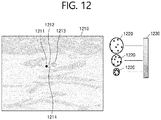
FIG. 12 illustrates an example of a screen on which the variance of the phase is displayed as a characteristic of the microcalcified tissue. - The
display unit 340 may display, on the ultrasonic image, animage 1210 in whichregions regions - Further, the
display unit 340 may further display acolor bar 1230 representing the plurality of colors corresponding to the values representing the characteristics of the microcalcified tissue. A figure 1220 ofFIG. 12 indicates that the variance of the phase of the microcalcification signal increases toward the top of thecolor bar 1230. As illustrated inFIG. 12 , thedisplay unit 340 may display theregion 1211, theregion 1212, and theregions -
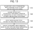
FIG. 13 is a flowchart illustrating a method of displaying an ultrasonic image according to the embodiment. - Operations of the method which will be described below may be performed by components of the
ultrasound diagnosis apparatus 300 illustrated inFIG. 3 . The above description related to theultrasound diagnosis apparatus 300 will be also applied to each operation of the following method. - In
operation 1310, theultrasound diagnosis apparatus 300 according to the embodiment may acquire the first data by transmitting the first ultrasonic pulse to the object and receiving the echo signal reflected from the object. - In
operation 1320, theultrasonic diagnosis apparatus 300 according to the embodiment may acquire the second data by repeatedly performing, a plurality of times at predetermined time intervals, an operation of transmitting the second ultrasonic pulse different from the first ultrasonic pulse to the object and receiving the echo signal reflected from the object. - The second ultrasonic pulse may be a pulse designed based on characteristics of the microcalcified tissue. For example, the second ultrasonic pulse may be an asymmetric pulse in which a negative pressure component is dominant as compared to a positive pressure component and may have a wavelength longer than that of the first ultrasonic pulse.
- In
operation 1330, theultrasound diagnosis apparatus 300 according to the embodiment may detect the microcalcified tissue in the object by analyzing the second data. - The
ultrasound diagnosis apparatus 300 may detect only the microcalcification signal, while independently distinguishing the microcalcification from the general tissue, by spatiotemporally analyzing a radio frequency (RF) signal or an I/Q signal received in response to the ultrasonic pulse transmitted to the object, a method of estimating a power, an average frequency, or a variance using the spatiotemporal signal characteristic analysis function (for example, the autocorrelation function) may be used as a method of detecting the microcalcification signal. - In detail, the
ultrasound diagnosis apparatus 300 may reconstruct the second data acquired in operation S1320 into the three-dimensional data including the information on the axial depth, the lateral width, and time. Theultrasound diagnosis apparatus 300 may extract the microcalcified tissue by analyzing the three-dimensional data. - The
ultrasound diagnosis apparatus 300 may estimate at least one of the intensity, the frequency, and the phase of the echo signal reflected from each region of the object by applying the SVD to the second data and may detect the microcalcified tissue in the object based on the estimated value. - The
ultrasound diagnosis apparatus 300 may calculate, based on the second data, the variance of the phase change over time of the echo signal reflected from each region of the object and detect a region in which the variance of the phase change is larger than or equal to a predetermined value as the microcalcified tissue in the object. - In
operation 1340, theultrasound diagnosis apparatus 300 according to the embodiment may display the ultrasonic image generated based on the first data and the image representing the detected microcalcified tissue. - The
ultrasound diagnosis apparatus 300 may generate the ultrasonic image by reconstructing the first data and generate the microcalcification image by reconstructing the microcalcification signal detected inoperation 1330 for the purpose of displaying the microcalcification signal on a screen. - The
ultrasound diagnosis apparatus 300 may individually display the ultrasonic image and the image representing the microcalcified tissue in different regions. Alternatively, theultrasound diagnosis apparatus 300 may display one image by fusing the ultrasonic image and the image representing the microcalcified tissue. Theultrasound diagnosis apparatus 300 may display one image on which a region corresponding to the microcalcified tissue detected on the ultrasonic image is marked. - For example, the ultrasonic image generated based on the first data may be the B mode image representing the cross-section of the object, and the image representing the microcalcified tissue may be an image on which the location of the microcalcified tissue inside the cross-section is marked using color, contrast, a symbol, a figure, flickering, or the like.
- The
ultrasound diagnosis apparatus 300 may further display the color bar representing the plurality of colors corresponding to the values representing the characteristics of the microcalcified tissue. Theultrasound diagnosis apparatus 300 may select a color from the color bar based on a value representing the characteristics of the detected microcalcified tissue and may display the selected color in a region corresponding to the detected microcalcified tissue. For example, the values representing the characteristics of the microcalcified tissue may indicate the variance of the phase change over time of the echo signal reflected from the microcalcified tissue. - For example, the ultrasonic image generated based on the first data may be the B mode image representing the cross-section of the object, and the image representing the microcalcified tissue may be an image on which the location of the microcalcified tissue inside the cross-section is marked using color, contrast, a symbol, a figure, flickering, or the like.
- The disclosed embodiments may be implemented as a software (S/W) program including a command stored in a computer-readable storage medium.
- A computer, which is an apparatus capable of calling a stored command from a storage medium and operating according to the disclosed embodiments according to the called command, may include the ultrasound diagnosis apparatus according to the disclosed embodiments.
- The computer-readable storage medium may be provided in the form of a non-transitory storage medium. Here, non-transitory means that the storage medium does not include a signal and is tangible but does not distinguish that data is semi-permanently or temporarily stored in the storage medium.
- Further, the ultrasound diagnosis apparatus or method according to the disclosed embodiments may be included and provided in a computer program product. The computer program product may be traded between sellers and buyers as a product.
- The computer program product may include a S/W program and a computer-readable storage medium in which the S/W program is stored. For example, the computer program product may include a product (for example, a downloadable application) in the form of a S/W program, which is electronically distributed through a manufacturer of the ultrasound diagnosis apparatus or an electronic market (for example, Google Play Store and App Store). For the electronic distribution, at least a part of the S/W program may be stored in the storage medium or may be temporarily generated. In this case, the storage medium may be a storage medium of a server of a manufacturer, a server of an electronic market, or a relay server temporarily storing the S/W program.
- The computer program product may include a storage medium of a server or a storage medium of a terminal in a system including the server and the terminal (for example, the ultrasound diagnosis apparatus). Alternatively, when there is a third device (for example, a smartphone) that is communicatively connected to the server or terminal, the computer program product may include a storage medium of the third device. Alternatively, the computer program product may include the S/W program itself transmitted from the server to the terminal or the third device or transmitted from the third device to the terminal.
- In this case, one of the server, the terminal, and the third device may execute the computer program product to perform the method according to the disclosed embodiments. Alternatively, two or more of the server, the terminal, and the third device may execute the computer program product to distribute and implement the method according to the disclosed embodiments.
- For example, the server (for example, a cloud server, an artificial intelligence server, or the like) may execute the computer program product stored in the server to control the terminal communicatively connected to the server to perform the method according to the disclosed embodiments.
- As another example, the third device may execute the computer program product to control the terminal communicatively connected to the third device to perform the method according to the disclosed embodiments. As a specific example, the third device may remotely control the ultrasound diagnosis apparatus to irradiate the object with the ultrasonic signal and generate an image of a part inside the object based on information on a signal reflected from the object.
- As another example, the third device may execute the computer program product to directly perform the method according to the disclosed embodiment based on a value input from an auxiliary device (for example, a probe of a medical device). As a specific example, the auxiliary device may irradiate the object with the ultrasonic signal and acquire the ultrasonic signal reflected from the object. The third device may receive information on the reflected signal from the auxiliary device and may generate an image of a part inside the object based on the input information on the reflected signal.
- When the third device executes the computer program product, the third device may download the computer program product from the server and execute the downloaded computer program product. Alternatively, the third device may execute the computer program product provided in a preloaded state to perform the method according to the disclosed embodiments.
Claims (15)
- A method of displaying an ultrasonic image, the method comprising:acquiring first data by transmitting a first ultrasonic pulse to an object and by receiving an echo signal reflected from the object;acquiring second data by repeatedly performing, a plurality of times at predetermined time intervals, an operation of transmitting a second ultrasonic pulse different from the first ultrasonic pulse to the object and receiving an echo signal reflected from the object;detecting microcalcified tissue in the object by analyzing the second data; anddisplaying an ultrasonic image generated based on the first data and an image representing the detected microcalcified tissue.
- The method of claim 1, wherein the second ultrasonic pulse is a pulse designed based on characteristics of microcalcified tissue.
- The method of claim 2, wherein the second ultrasonic pulse is an asymmetric pulse in which a negative pressure component is dominant as compared to a positive pressure component and has a wavelength that is longer than a wavelength of the first ultrasonic pulse.
- The method of claim 1, wherein the detecting of the microcalcified tissue includes:reconstructing the second data into three-dimensional data including information on an axial depth, a lateral width, and time; andextracting the microcalcified tissue by analyzing the three-dimensional data.
- The method of claim 1, wherein the detecting of the microcalcified tissue includes:estimating at least one of an intensity, a frequency and a phase of the echo signal reflected from each region of the object by applying singular value decomposition (SVD) to the second data; anddetecting the microcalcified tissue in the object based on the estimated value.
- The method of claim 1, wherein the detecting of the microcalcified tissue includes:calculating a variance of a phase change over time of the echo signal reflected from each region of the object, based on the second data; anddetecting a region in which the variance of the phase change is larger than or equal to a predetermined value as the microcalcified tissue in the object.
- The method of claim 1, wherein the displaying of the ultrasonic image and the image representing the detected microcalcified tissue includes:displaying a color bar representing a plurality of colors corresponding to values representing characteristics of microcalcified tissue;selecting a color from the color bar based on a value representing the characteristics of the detected microcalcified tissue; anddisplaying the selected color in a region included in the ultrasonic image and corresponding to the detected microcalcified tissue.
- The method of claim 7, wherein the values representing the characteristics of the microcalcified tissue represent a variance of a phase change over time of the echo signal reflected from the microcalcified tissue.
- The method of claim 1, wherein:the ultrasonic image is a B mode image of a cross-section of the object; andthe displaying of the ultrasonic image and the image representing the detected microcalcified tissue includes displaying the region corresponding to the detected microcalcified tissue on the ultrasonic image.
- An ultrasound diagnosis apparatus comprising:an ultrasonic transceiver configured to acquire first data by allowing a probe to transmit a first ultrasonic pulse to an object and to receive an echo signal reflected from the object and configured to acquire second data by allowing the probe to repeatedly perform, a plurality of times at predetermined time intervals, an operation of transmitting a second ultrasonic pulse different from the first ultrasonic pulse to the object and receiving an echo signal reflected from the object;a controller configured to detect microcalcified tissue in the object by analyzing the second data; anda display unit configured to display an ultrasonic image generated based on the first data and an image representing the detected microcalcified tissue.
- The ultrasound diagnosis apparatus of claim 10, wherein the second ultrasonic pulse, as a pulse designed based on characteristics of microcalcified tissue, is an asymmetric pulse in which a negative pressure component is dominant as compared to a positive pressure component and has a wavelength that is longer than a wavelength of the first ultrasonic pulse.
- The ultrasound diagnosis apparatus of claim 10, wherein, in the detecting of the microcalcified tissue, the controller reconstructs the second data into three-dimensional data including information on an axial depth, a lateral width, and time, and extracts the microcalcified tissue by analyzing the three-dimensional data.
- The ultrasound diagnosis apparatus of claim 10, wherein, in the detecting of the microcalcified tissue, the controller calculates, based on the second data, a variance of a phase change over time of the echo signal reflected from each region of the object and detects a region in which the variance of the phase change is larger than or equal to a predetermined value, as the microcalcified tissue in the object.
- The ultrasound diagnosis apparatus of claim 10, wherein:the display unit displays a color bar representing a plurality of colors corresponding to values representing characteristics of microcalcified tissue, selects a color from the color bar based on a value representing the characteristics of the detected microcalcified tissue, and displays the selected color in a region included in the ultrasonic image and corresponding to the detected microcalcified tissue; andthe values representing the characteristics of the microcalcified tissue represent a variance of a phase change over time of the echo signal reflected from the microcalcified tissue.
- A computer program product including a storage medium configured to store computer program code for performing the method of displaying an ultrasonic image of claim 1.
Applications Claiming Priority (2)
| Application Number | Priority Date | Filing Date | Title |
|---|---|---|---|
| KR1020180093141A KR102714846B1 (en) | 2018-08-09 | 2018-08-09 | Ultrasound diagnosis apparatus, method for displaying ultrasound image and computer program product |
| PCT/KR2019/003263 WO2020032341A1 (en) | 2018-08-09 | 2019-03-20 | Ultrasound diagnosis apparatus, method for displaying ultrasound image, and computer program product |
Publications (2)
| Publication Number | Publication Date |
|---|---|
| EP3834735A1 true EP3834735A1 (en) | 2021-06-16 |
| EP3834735A4 EP3834735A4 (en) | 2022-05-11 |
Family
ID=69414242
Family Applications (1)
| Application Number | Title | Priority Date | Filing Date |
|---|---|---|---|
| EP19846190.7A Pending EP3834735A4 (en) | 2018-08-09 | 2019-03-20 | ULTRASOUND DIAGNOSTIC APPARATUS, ULTRASOUND IMAGE DISPLAY METHOD, AND COMPUTER PROGRAM PRODUCT |
Country Status (4)
| Country | Link |
|---|---|
| US (1) | US12076191B2 (en) |
| EP (1) | EP3834735A4 (en) |
| KR (1) | KR102714846B1 (en) |
| WO (1) | WO2020032341A1 (en) |
Families Citing this family (1)
| Publication number | Priority date | Publication date | Assignee | Title |
|---|---|---|---|---|
| KR102837440B1 (en) * | 2024-08-12 | 2025-07-23 | 주식회사 엣지케어 | Detection device for calcification |
Citations (3)
| Publication number | Priority date | Publication date | Assignee | Title |
|---|---|---|---|---|
| WO2005124385A1 (en) * | 2004-06-14 | 2005-12-29 | Bae Systems Information And Electronic Systems Integration Inc. | Multi-ship coherent geolocation system |
| EP2530022A1 (en) * | 2011-06-01 | 2012-12-05 | Thales | System for geographical positioning of a radio-frequency signal transmitter located on the surface of the earth, and associated distributed interferometry method. |
| US9661604B1 (en) * | 2016-06-30 | 2017-05-23 | HawkEye 360, Inc. | Determining emitter locations |
Family Cites Families (26)
| Publication number | Priority date | Publication date | Assignee | Title |
|---|---|---|---|---|
| JP2003310587A (en) | 2002-04-26 | 2003-11-05 | Fuji Photo Film Co Ltd | Display device for abnormal shadow detected result |
| US20050277835A1 (en) * | 2003-05-30 | 2005-12-15 | Angelsen Bjorn A | Ultrasound imaging by nonlinear low frequency manipulation of high frequency scattering and propagation properties |
| EP2287632A1 (en) | 2004-07-23 | 2011-02-23 | Bjorn A. J. Angelsen | Ultrasound imaging using non-linear manipulation of forward propagation properties of a pulse |
| US8834371B2 (en) | 2005-03-31 | 2014-09-16 | Kabushiki Kaisha Toshiba | Ultrasound diagnostic apparatus and ultrasound image processing program |
| KR100762746B1 (en) | 2006-03-07 | 2007-10-02 | 재단법인서울대학교산학협력재단 | Microcalcification Diagnostic System and Method |
| WO2007114375A1 (en) * | 2006-03-31 | 2007-10-11 | Kabushiki Kaisha Toshiba | Ultrasound diagnostic device and control method for ultrasound diagnostic device |
| JP5052123B2 (en) * | 2006-12-27 | 2012-10-17 | 富士フイルム株式会社 | Medical imaging system and method |
| JP5067253B2 (en) | 2008-04-23 | 2012-11-07 | コニカミノルタエムジー株式会社 | Ultrasonic diagnostic equipment |
| KR101030594B1 (en) | 2009-07-02 | 2011-04-21 | 국립암센터 | Diagnostic method of microcalcification |
| KR101067441B1 (en) | 2009-08-14 | 2011-09-27 | 서울과학기술대학교 산학협력단 | Microcalcification Detection Method Using Fourier Transform |
| KR101117545B1 (en) | 2010-04-01 | 2012-03-07 | 대진대학교 산학협력단 | Ultrasound Diagnostic System and Method For Forming Elasticity Image Using Overlapped Plane Wave |
| US8109878B1 (en) | 2010-09-14 | 2012-02-07 | Quantason, LLC | Use of coded excitation schemes in the detection and location of a target in a human body such as breast calcifications |
| US8622909B1 (en) * | 2010-10-19 | 2014-01-07 | Quantason, LLC | Method of locating the position of a microcalcification in a human breast |
| WO2012077130A1 (en) | 2010-12-06 | 2012-06-14 | Indian Institute Of Technology, Kharagpur | Method and system to detect the microcalcifications in x-ray images using nonlinear energy operator. |
| KR20120102447A (en) | 2011-03-08 | 2012-09-18 | 삼성전자주식회사 | Method and apparatus for diagnostic |
| KR101287099B1 (en) | 2011-10-11 | 2013-07-16 | 서강대학교산학협력단 | Method of producing photoacoustic image for detecting calcification tissue and producing apparatus thereof |
| WO2013116783A1 (en) | 2012-02-03 | 2013-08-08 | Los Alamos National Security, Llc | Windowed time-reversal music technique for super-resolution ultrasound imaging |
| JP6195850B2 (en) | 2012-02-24 | 2017-09-13 | パウル・シェラー・インスティトゥート | Several different types of non-invasive classification systems for microcalcification of human tissue |
| KR20140059466A (en) * | 2012-11-08 | 2014-05-16 | 이화여자대학교 산학협력단 | Apparatus for photoacoustic scanning for diagnosis of breast cancer |
| US10357224B2 (en) | 2013-03-20 | 2019-07-23 | Koninklijke Philips N.V. | Beamforming techniques for ultrasound microcalcification detection |
| KR102256703B1 (en) * | 2013-07-02 | 2021-05-27 | 삼성전자주식회사 | Ultrasonic diagnostic apparatus and operating method for the same |
| EP3081169B1 (en) * | 2013-12-12 | 2023-06-28 | Samsung Medison Co., Ltd. | Method and apparatus for displaying ultrasonic image |
| US11058401B2 (en) | 2014-01-23 | 2021-07-13 | Super Sonic Imagine | Method for determining a physical characteristic on a punctual location inside a medium, a method for determining an image of a medium, and an apparatus implementing said methods |
| US20150320383A1 (en) | 2014-05-06 | 2015-11-12 | University Of Washington | Methods and Systems for Estimating a Size of an Object in a Subject with Ultrasound |
| JP6158143B2 (en) * | 2014-07-18 | 2017-07-05 | ジーイー・メディカル・システムズ・グローバル・テクノロジー・カンパニー・エルエルシー | Calcification display device, photographing device and program |
| KR101956460B1 (en) * | 2017-08-09 | 2019-03-08 | 서강대학교산학협력단 | Method for detecting microcalcification using ultrasound medical imaging device and ultrasound medical imaging device thereof |
-
2018
- 2018-08-09 KR KR1020180093141A patent/KR102714846B1/en active Active
-
2019
- 2019-03-20 EP EP19846190.7A patent/EP3834735A4/en active Pending
- 2019-03-20 US US17/267,133 patent/US12076191B2/en active Active
- 2019-03-20 WO PCT/KR2019/003263 patent/WO2020032341A1/en not_active Ceased
Patent Citations (3)
| Publication number | Priority date | Publication date | Assignee | Title |
|---|---|---|---|---|
| WO2005124385A1 (en) * | 2004-06-14 | 2005-12-29 | Bae Systems Information And Electronic Systems Integration Inc. | Multi-ship coherent geolocation system |
| EP2530022A1 (en) * | 2011-06-01 | 2012-12-05 | Thales | System for geographical positioning of a radio-frequency signal transmitter located on the surface of the earth, and associated distributed interferometry method. |
| US9661604B1 (en) * | 2016-06-30 | 2017-05-23 | HawkEye 360, Inc. | Determining emitter locations |
Non-Patent Citations (1)
| Title |
|---|
| See also references of WO2020032341A1 * |
Also Published As
| Publication number | Publication date |
|---|---|
| WO2020032341A1 (en) | 2020-02-13 |
| KR20200017791A (en) | 2020-02-19 |
| US12076191B2 (en) | 2024-09-03 |
| US20210186464A1 (en) | 2021-06-24 |
| EP3834735A4 (en) | 2022-05-11 |
| KR102714846B1 (en) | 2024-10-10 |
Similar Documents
| Publication | Publication Date | Title |
|---|---|---|
| KR101797042B1 (en) | Method and apparatus for synthesizing medical images | |
| US10832405B2 (en) | Medical image processing apparatus with awareness of type of subject pattern | |
| US10646203B2 (en) | Ultrasound diagnosis method and apparatus for analyzing contrast enhanced ultrasound image | |
| CN101896123A (en) | Robotic ultrasound system with microadjustment and positioning control using feedback responsive to acquired image data | |
| US11564663B2 (en) | Ultrasound imaging apparatus and control method thereof | |
| EP4082441B1 (en) | Ultrasound diagnostic apparatus and method for operating same | |
| JP7215053B2 (en) | Ultrasonic image evaluation device, ultrasonic image evaluation method, and ultrasonic image evaluation program | |
| CN112773403A (en) | Ultrasonic imaging method and system | |
| KR20170086311A (en) | Medical imaging apparatus and operating method for the same | |
| JP2025188308A (en) | Ultrasonic image diagnostic apparatus, discriminator change method and discriminator change program | |
| EP3854313B1 (en) | Ultrasound diagnostic apparatus and method of controlling the same | |
| KR102439765B1 (en) | Apparatus and method for displaying ultrasound image | |
| US20150206323A1 (en) | Method and apparatus for displaying medical image | |
| US12076191B2 (en) | Ultrasound diagnosis apparatus, method for displaying ultrasound image, and computer program product | |
| CN115551416B (en) | Measurement of hip | |
| KR20200093943A (en) | Medical imaging apparatus and operating method for the same | |
| KR20190016816A (en) | Method for detecting microcalcification using ultrasound medical imaging device and ultrasound medical imaging device thereof | |
| CN114098687B (en) | Method and system for automatic heart rate measurement in ultrasound motion mode | |
| CN112990267B (en) | Breast ultrasound imaging method, device and storage medium based on style transfer model | |
| KR20250158917A (en) | Ultrasound imaging system and method for controlling thereof | |
| JP2021194058A (en) | Ultrasonic blood flow area calculation device, method, and program, and ultrasonic image diagnostic device | |
| KR20190008055A (en) | Ultrasound diagnosis apparatus and operating method for the same |
Legal Events
| Date | Code | Title | Description |
|---|---|---|---|
| STAA | Information on the status of an ep patent application or granted ep patent |
Free format text: STATUS: THE INTERNATIONAL PUBLICATION HAS BEEN MADE |
|
| PUAI | Public reference made under article 153(3) epc to a published international application that has entered the european phase |
Free format text: ORIGINAL CODE: 0009012 |
|
| STAA | Information on the status of an ep patent application or granted ep patent |
Free format text: STATUS: REQUEST FOR EXAMINATION WAS MADE |
|
| 17P | Request for examination filed |
Effective date: 20210204 |
|
| AK | Designated contracting states |
Kind code of ref document: A1 Designated state(s): AL AT BE BG CH CY CZ DE DK EE ES FI FR GB GR HR HU IE IS IT LI LT LU LV MC MK MT NL NO PL PT RO RS SE SI SK SM TR |
|
| RIN1 | Information on inventor provided before grant (corrected) |
Inventor name: KIM, KANGSIK Inventor name: YOO, YANGMO Inventor name: KANG, JINBUM Inventor name: KIM, JUNGHO Inventor name: GO, DOOYOUNG Inventor name: BAEK, JIHYE |
|
| DAV | Request for validation of the european patent (deleted) | ||
| DAX | Request for extension of the european patent (deleted) | ||
| A4 | Supplementary search report drawn up and despatched |
Effective date: 20220408 |
|
| RIC1 | Information provided on ipc code assigned before grant |
Ipc: G01S 7/52 20060101ALI20220404BHEP Ipc: A61B 8/00 20060101ALI20220404BHEP Ipc: A61B 8/08 20060101AFI20220404BHEP |
|
| STAA | Information on the status of an ep patent application or granted ep patent |
Free format text: STATUS: EXAMINATION IS IN PROGRESS |
|
| 17Q | First examination report despatched |
Effective date: 20240327 |