EP3834347B1 - Uci design for ul transmission with configured grant - Google Patents
Uci design for ul transmission with configured grant Download PDFInfo
- Publication number
- EP3834347B1 EP3834347B1 EP19758570.6A EP19758570A EP3834347B1 EP 3834347 B1 EP3834347 B1 EP 3834347B1 EP 19758570 A EP19758570 A EP 19758570A EP 3834347 B1 EP3834347 B1 EP 3834347B1
- Authority
- EP
- European Patent Office
- Prior art keywords
- uci
- wireless communications
- communications device
- mcs
- pusch
- Prior art date
- Legal status (The legal status is an assumption and is not a legal conclusion. Google has not performed a legal analysis and makes no representation as to the accuracy of the status listed.)
- Active
Links
- 230000005540 biological transmission Effects 0.000 title claims description 48
- 238000013461 design Methods 0.000 title description 5
- 238000004891 communication Methods 0.000 claims description 97
- 238000000034 method Methods 0.000 claims description 33
- 230000015654 memory Effects 0.000 claims description 25
- 230000007480 spreading Effects 0.000 claims description 22
- 238000003892 spreading Methods 0.000 claims description 22
- 238000013507 mapping Methods 0.000 claims description 21
- 125000004122 cyclic group Chemical group 0.000 claims description 16
- 230000011664 signaling Effects 0.000 claims description 8
- 230000007704 transition Effects 0.000 claims description 5
- 230000001960 triggered effect Effects 0.000 claims 1
- 238000005516 engineering process Methods 0.000 description 32
- 238000010586 diagram Methods 0.000 description 25
- 230000006870 function Effects 0.000 description 17
- 230000004913 activation Effects 0.000 description 9
- 238000007726 management method Methods 0.000 description 9
- 238000003860 storage Methods 0.000 description 8
- 230000002093 peripheral effect Effects 0.000 description 7
- 230000008901 benefit Effects 0.000 description 6
- 230000008569 process Effects 0.000 description 6
- 238000013468 resource allocation Methods 0.000 description 6
- 230000001413 cellular effect Effects 0.000 description 5
- 230000007246 mechanism Effects 0.000 description 5
- 230000003044 adaptive effect Effects 0.000 description 4
- 101150014732 asnS gene Proteins 0.000 description 4
- 238000012545 processing Methods 0.000 description 4
- 238000012546 transfer Methods 0.000 description 4
- 241000760358 Enodes Species 0.000 description 3
- 230000009849 deactivation Effects 0.000 description 3
- 230000007774 longterm Effects 0.000 description 3
- 238000001228 spectrum Methods 0.000 description 3
- 230000000007 visual effect Effects 0.000 description 3
- 108010003272 Hyaluronate lyase Proteins 0.000 description 2
- 101150071746 Pbsn gene Proteins 0.000 description 2
- 238000013459 approach Methods 0.000 description 2
- 238000013475 authorization Methods 0.000 description 2
- 230000009286 beneficial effect Effects 0.000 description 2
- 230000003595 spectral effect Effects 0.000 description 2
- 102100038824 Peroxisome proliferator-activated receptor delta Human genes 0.000 description 1
- 241000700159 Rattus Species 0.000 description 1
- 230000006978 adaptation Effects 0.000 description 1
- 230000002776 aggregation Effects 0.000 description 1
- 238000004220 aggregation Methods 0.000 description 1
- 238000004873 anchoring Methods 0.000 description 1
- 230000003190 augmentative effect Effects 0.000 description 1
- 239000003795 chemical substances by application Substances 0.000 description 1
- 238000011161 development Methods 0.000 description 1
- 238000009826 distribution Methods 0.000 description 1
- 230000000694 effects Effects 0.000 description 1
- 230000002708 enhancing effect Effects 0.000 description 1
- 238000005562 fading Methods 0.000 description 1
- 239000000446 fuel Substances 0.000 description 1
- 239000004973 liquid crystal related substance Substances 0.000 description 1
- 239000011159 matrix material Substances 0.000 description 1
- 230000005055 memory storage Effects 0.000 description 1
- 238000013508 migration Methods 0.000 description 1
- 230000005012 migration Effects 0.000 description 1
- 238000010295 mobile communication Methods 0.000 description 1
- 238000012544 monitoring process Methods 0.000 description 1
- 230000003287 optical effect Effects 0.000 description 1
- 239000013307 optical fiber Substances 0.000 description 1
- 238000005457 optimization Methods 0.000 description 1
- 230000000737 periodic effect Effects 0.000 description 1
- 108091008765 peroxisome proliferator-activated receptors β/δ Proteins 0.000 description 1
- 230000010363 phase shift Effects 0.000 description 1
- 230000026676 system process Effects 0.000 description 1
- 230000008685 targeting Effects 0.000 description 1
- 238000013519 translation Methods 0.000 description 1
Images


Classifications
-
- H—ELECTRICITY
- H04—ELECTRIC COMMUNICATION TECHNIQUE
- H04L—TRANSMISSION OF DIGITAL INFORMATION, e.g. TELEGRAPHIC COMMUNICATION
- H04L5/00—Arrangements affording multiple use of the transmission path
- H04L5/0091—Signaling for the administration of the divided path
- H04L5/0094—Indication of how sub-channels of the path are allocated
-
- H—ELECTRICITY
- H04—ELECTRIC COMMUNICATION TECHNIQUE
- H04W—WIRELESS COMMUNICATION NETWORKS
- H04W72/00—Local resource management
- H04W72/20—Control channels or signalling for resource management
- H04W72/23—Control channels or signalling for resource management in the downlink direction of a wireless link, i.e. towards a terminal
-
- H—ELECTRICITY
- H04—ELECTRIC COMMUNICATION TECHNIQUE
- H04L—TRANSMISSION OF DIGITAL INFORMATION, e.g. TELEGRAPHIC COMMUNICATION
- H04L5/00—Arrangements affording multiple use of the transmission path
- H04L5/003—Arrangements for allocating sub-channels of the transmission path
- H04L5/0053—Allocation of signaling, i.e. of overhead other than pilot signals
-
- H—ELECTRICITY
- H04—ELECTRIC COMMUNICATION TECHNIQUE
- H04L—TRANSMISSION OF DIGITAL INFORMATION, e.g. TELEGRAPHIC COMMUNICATION
- H04L1/00—Arrangements for detecting or preventing errors in the information received
- H04L1/0001—Systems modifying transmission characteristics according to link quality, e.g. power backoff
- H04L1/0002—Systems modifying transmission characteristics according to link quality, e.g. power backoff by adapting the transmission rate
- H04L1/0003—Systems modifying transmission characteristics according to link quality, e.g. power backoff by adapting the transmission rate by switching between different modulation schemes
- H04L1/0004—Systems modifying transmission characteristics according to link quality, e.g. power backoff by adapting the transmission rate by switching between different modulation schemes applied to control information
-
- H—ELECTRICITY
- H04—ELECTRIC COMMUNICATION TECHNIQUE
- H04L—TRANSMISSION OF DIGITAL INFORMATION, e.g. TELEGRAPHIC COMMUNICATION
- H04L1/00—Arrangements for detecting or preventing errors in the information received
- H04L1/0001—Systems modifying transmission characteristics according to link quality, e.g. power backoff
- H04L1/0023—Systems modifying transmission characteristics according to link quality, e.g. power backoff characterised by the signalling
- H04L1/0025—Transmission of mode-switching indication
-
- H—ELECTRICITY
- H04—ELECTRIC COMMUNICATION TECHNIQUE
- H04L—TRANSMISSION OF DIGITAL INFORMATION, e.g. TELEGRAPHIC COMMUNICATION
- H04L1/00—Arrangements for detecting or preventing errors in the information received
- H04L1/004—Arrangements for detecting or preventing errors in the information received by using forward error control
- H04L1/0056—Systems characterized by the type of code used
- H04L1/0061—Error detection codes
-
- H—ELECTRICITY
- H04—ELECTRIC COMMUNICATION TECHNIQUE
- H04L—TRANSMISSION OF DIGITAL INFORMATION, e.g. TELEGRAPHIC COMMUNICATION
- H04L1/00—Arrangements for detecting or preventing errors in the information received
- H04L1/004—Arrangements for detecting or preventing errors in the information received by using forward error control
- H04L1/0056—Systems characterized by the type of code used
- H04L1/0071—Use of interleaving
-
- H—ELECTRICITY
- H04—ELECTRIC COMMUNICATION TECHNIQUE
- H04L—TRANSMISSION OF DIGITAL INFORMATION, e.g. TELEGRAPHIC COMMUNICATION
- H04L1/00—Arrangements for detecting or preventing errors in the information received
- H04L1/12—Arrangements for detecting or preventing errors in the information received by using return channel
- H04L1/16—Arrangements for detecting or preventing errors in the information received by using return channel in which the return channel carries supervisory signals, e.g. repetition request signals
- H04L1/18—Automatic repetition systems, e.g. Van Duuren systems
- H04L1/1812—Hybrid protocols; Hybrid automatic repeat request [HARQ]
- H04L1/1819—Hybrid protocols; Hybrid automatic repeat request [HARQ] with retransmission of additional or different redundancy
-
- H—ELECTRICITY
- H04—ELECTRIC COMMUNICATION TECHNIQUE
- H04L—TRANSMISSION OF DIGITAL INFORMATION, e.g. TELEGRAPHIC COMMUNICATION
- H04L1/00—Arrangements for detecting or preventing errors in the information received
- H04L1/12—Arrangements for detecting or preventing errors in the information received by using return channel
- H04L1/16—Arrangements for detecting or preventing errors in the information received by using return channel in which the return channel carries supervisory signals, e.g. repetition request signals
- H04L1/18—Automatic repetition systems, e.g. Van Duuren systems
- H04L1/1867—Arrangements specially adapted for the transmitter end
- H04L1/1896—ARQ related signaling
-
- H—ELECTRICITY
- H04—ELECTRIC COMMUNICATION TECHNIQUE
- H04L—TRANSMISSION OF DIGITAL INFORMATION, e.g. TELEGRAPHIC COMMUNICATION
- H04L5/00—Arrangements affording multiple use of the transmission path
- H04L5/0001—Arrangements for dividing the transmission path
- H04L5/0014—Three-dimensional division
- H04L5/0016—Time-frequency-code
-
- H—ELECTRICITY
- H04—ELECTRIC COMMUNICATION TECHNIQUE
- H04L—TRANSMISSION OF DIGITAL INFORMATION, e.g. TELEGRAPHIC COMMUNICATION
- H04L5/00—Arrangements affording multiple use of the transmission path
- H04L5/003—Arrangements for allocating sub-channels of the transmission path
- H04L5/0048—Allocation of pilot signals, i.e. of signals known to the receiver
- H04L5/0051—Allocation of pilot signals, i.e. of signals known to the receiver of dedicated pilots, i.e. pilots destined for a single user or terminal
-
- H—ELECTRICITY
- H04—ELECTRIC COMMUNICATION TECHNIQUE
- H04L—TRANSMISSION OF DIGITAL INFORMATION, e.g. TELEGRAPHIC COMMUNICATION
- H04L5/00—Arrangements affording multiple use of the transmission path
- H04L5/0091—Signaling for the administration of the divided path
- H04L5/0092—Indication of how the channel is divided
-
- H—ELECTRICITY
- H04—ELECTRIC COMMUNICATION TECHNIQUE
- H04W—WIRELESS COMMUNICATION NETWORKS
- H04W72/00—Local resource management
- H04W72/04—Wireless resource allocation
- H04W72/044—Wireless resource allocation based on the type of the allocated resource
- H04W72/0446—Resources in time domain, e.g. slots or frames
-
- H—ELECTRICITY
- H04—ELECTRIC COMMUNICATION TECHNIQUE
- H04W—WIRELESS COMMUNICATION NETWORKS
- H04W72/00—Local resource management
- H04W72/04—Wireless resource allocation
- H04W72/044—Wireless resource allocation based on the type of the allocated resource
- H04W72/0453—Resources in frequency domain, e.g. a carrier in FDMA
-
- H—ELECTRICITY
- H04—ELECTRIC COMMUNICATION TECHNIQUE
- H04W—WIRELESS COMMUNICATION NETWORKS
- H04W72/00—Local resource management
- H04W72/12—Wireless traffic scheduling
- H04W72/1263—Mapping of traffic onto schedule, e.g. scheduled allocation or multiplexing of flows
- H04W72/1268—Mapping of traffic onto schedule, e.g. scheduled allocation or multiplexing of flows of uplink data flows
-
- H—ELECTRICITY
- H04—ELECTRIC COMMUNICATION TECHNIQUE
- H04W—WIRELESS COMMUNICATION NETWORKS
- H04W72/00—Local resource management
- H04W72/20—Control channels or signalling for resource management
- H04W72/21—Control channels or signalling for resource management in the uplink direction of a wireless link, i.e. towards the network
-
- H—ELECTRICITY
- H04—ELECTRIC COMMUNICATION TECHNIQUE
- H04W—WIRELESS COMMUNICATION NETWORKS
- H04W72/00—Local resource management
- H04W72/04—Wireless resource allocation
- H04W72/115—Grant-free or autonomous transmission
Definitions
- NOMA non-orthogonal multiple access
- a gNB may not know when a UE is to perform an UL transmission or may not know the identity of the UE.
- the UE may be configured with dedicated demodulation reference signal (DMRS), so that the gNB may identify the UE by detecting the corresponding DMRS.
- DMRS dedicated demodulation reference signal
- MCS adaptive modulation and coding scheme
- the gNB may need to be notified of the MCS level used by the UE to decode the data.
- 3GPP document R1-1806533 (May 21st - 25th, 2018) entitled “NOMA related procedure" discusses grant free UL NOMA related procedures.
- UCI uplink control information
- LTE Long Term Evolution
- NOMA non-orthogonal multiple access
- the first NOMA application in LTE was introduced for the downlink (DL).
- the DL NOMA was proposed, and then the necessary mechanisms were investigated to enable LTE to support DL intra-cell multiuser superposition transmission (MUST) for data channels with assistance information from a serving Base Station (BS) to a user equipment (UE) with respect to whether it experienced intra-cell interference.
- MUST DL intra-cell multiuser superposition transmission
- BS Base Station
- UE user equipment
- NOMA has also been discussed for use in 5G NR.
- numerous NOMA schemes have been proposed, mainly targeting uplink (UL) transmissions to support massive connectivity.
- FIG. 1 shows an example NOMA scheme 100.
- FIG. 1 shows, for multiple UEs, the given frequency 51, time 53, and the code/sequence/interleaver 52.
- UEs 56, 57, 58, and 59 may be multiplexing at a given time 55 and frequency (bandwidth (BW)) 54 resource when operating in a NOMA scheme.
- BW bandwidth
- a NOMA scheme when communicating using a NOMA scheme, there may be interference between transmissions using overlapping resources such as the overlapping resources being used by UEs 56, 57, 58, and 59 in the example of FIG. 1 .
- this non-orthogonal characteristic may be more pronounced.
- transmitter side schemes such as spreading (linear or non-linear, with or without sparseness) and interleaving may be employed to improve performance and ease the burden of advanced receivers.
- the NR NOMA candidate schemes may be categorized as three major types: codebook based, sequence based, and Interleaver or scrambling based.
- NOMA NOMA
- 5G NR 5G NR
- mMTC massive machine type communication
- URLLC massive machine type communication
- eMBB massive machine type communications
- NOMA is proposed to be adopted.
- the benefits may be summarized as follows:
- the benefits of adopting NOMA may include: providing higher connection density per physical resource with high overloading; and reducing latency, signaling overhead, and power consumption by enabling grant-free access.
- NOMA may enable efficient use of grant-free transmission and therefore may benefit URLLC low latency use cases.
- the benefits of adopting NOMA may also include: improving the efficiency of the resource utilization; providing higher reliability through diversity gain achieved by spreading and coding; enhancing the robustness to collision by carefully designing the MA signature; and providing the ability to multiplex mixed traffic types.
- the benefits of adopting NOMA may include: efficient resource utilization; larger capacity region by non-orthogonal user multiplexing; robustness to fading and interference with code-domain design; and higher cell throughput and efficient link adaptation with relaxed CSI accuracy.
- Configured grant type 1 An uplink grant is provided by RRC and stored as a configured uplink grant.
- DMRS Demodulation Reference Signal
- Configured grant type 2 An uplink grant is provided by PDCCH, and stored or cleared as a configured uplink grant based on L1 signaling indicating configured grant activation or deactivation.
- RRC may configure a UE with the periodicity, power control and repetitions of the configured grant.
- the activation downlink control information (DCI), which is carried by the PDCCH scrambled with the CS-RNTI, may indicate the offset, time domain resource allocation, frequency domain resource allocation, UE-specific DMRS configuration, MCS/TBS value, etc.
- DCI downlink control information
- Configured grant type 1 and type 2 may be configured by RRC per serving cell and per BWP. Multiple configurations may be activated simultaneously on different serving cells. For configured grant type 2, activation and deactivation may be independent among the serving cells.
- Uplink control information (UCI) reporting is supported in 5G NR.
- UCI may be reported in both the PUCCH and PUSCH.
- Types of UCI reported in a PUCCH may include HARQ-ACK information, SR, and CSI.
- a UE may be configured with a dedicated PUCCH resource configuration by the RRC.
- a PUCCH resource may include a PUCCH resource index, an index of the first PRB prior to frequency hopping, or for no frequency hopping, an index of the first PRB after frequency hopping, an indication for intra-slot frequency hopping, or a configuration for a PUCCH format.
- five PUCCH formats, from PUCCH format 0 to PUCCH format 4 are supported.
- the PUCCH formats may be distinguished by the length of the transmission symbols and the UCI payload bits as shown in Table 1 below.
- Table 1 PUCCH Formats Format type Length of symbols Number of bit Format 0 1 or 2 HARQ-ACK/SR bits is 1 or 2 Format 1 ⁇ 4 HARQ-ACK/SR bits is 1 or 2 Format 2 1 or 2 UCI bits is more than 2 Format 3 ⁇ 4 UCI bits is more than 2 Format 4 ⁇ 4 UCI bits is more than 2, the PUCCH resource includes an orthogonal cover code
- a UE may be configured up to four sets of PUCCH resources by higher layer parameter PUCCH-ResourceSet.
- the UE may determine the PUCCH resource set based on the size of the UCI information bits NUCI. Within one PUCCH resource set, the UE may determine the PUCCH resource based on the PUCCH resource indicator field indicated by the DCI.
- a UE may be configured with the PUCCH-Spatialrelationinfo to determine the spatial setting of a PUCCH transmission.
- the PUCCH-Spatialrelationinfo may be either an SSB index, CSI-RS Index, or SRS.
- the PUCCH-Spatialrelationinfo is an SSB index or CSI-RS Index
- the UE may transmit the PUCCH using a same spatial domain filter as for a reception of the configured SS/PBCH block or CSI-RS.
- the PUCCH-Spatialrelationinfo is SRS
- the UE may transmit the PUCCH using a same spatial domain filter as used in a transmission of the configured SRS.
- NR supports the UCI being piggybacked on the PUSCH for both the DFT-s-OFDM waveform and the CP-OFDM waveform, and the same UCI resource mapping principles may be used for the PUSCH with the DFT-s-OFDM waveform and the CP-OFDM waveform for frequency first mapping.
- the piggybacked UCI may include a HARQ-ACK, CSI part 1 and CSI part 2.
- different piggyback rules may be defined for the HARQ-ACK with different lengths.
- the PUSCH may be rate matched and the UL-SCH may perform rate matching around the resource elements (REs) piggybacking the HARQ-ACK.
- the HARQ-ACK is less than or equal to 2 bits, the PUSCH may be punctured, i.e., the UL-SCH is first mapped to all the available resources and then the HARQ-ACK punctures the UL-SCH in some reserved REs.
- both HARQ-ACK and CSI may be mapped in a distributed way to the REs across all the allocated PRBs.
- both the HARQ-ACK and CSI may be mapped to all layers of the transport block (TB) on the PUSCH in NR.
- Another difference with respect to LTE is that, instead of a fixed QPSK modulation in LTE, the modulation order of UCI in NR may follow the modulation order of the UL-SCH.
- the piggybacked UCI may be mapped after the front-loaded DMRS symbol. Within the symbol carrying the DMRS, no FDM is allowed. Starting from the first available non-DMRS symbol after the front-loaded DMRS symbol(s), the HARQ-ACK may first be mapped if it is piggybacked. If the remaining HARQ-ACK fills one entire allocated symbol, then it may occupy the whole symbol. Otherwise, the HARQ-ACK may be evenly mapped in a distributed way in the allocated resources in that symbol.
- CSI part 1 may be mapped using the same rules as the HARQ-ACK if it is piggybacked. When both the HARQ-ACK and CSI part 1 are piggybacked, CSI part 1 may not be mapped on the REs already piggybacking the HARQ-ACK for both the more than 2 bits and the less than or equal to 2 bits two scenarios. For the symbol carrying the HARQ-ACK but not fully occupied, CSI part 1 may first be mapped to the unused REs and then mapped to the following symbols.
- CSI part 2 For CSI part 2, the same rules as CSI part 1 may be applied except when the HARQ-ACK is ⁇ 2 bits, i.e., the PUSCH is punctured. In this scenario, CSI part 2 may be mapped on the reserved HARQ-ACK REs for puncturing and then let the HARQ-ACK puncture the CSI part 2 if it is piggybacked.
- the gNB may not know when a UE is to perform an UL transmission and the identity of the UE. So, the gNB may need to identify the UE activity first when it receives a packet (i.e. determine which UE has transmited the data).
- the UE may be configured with dedicated DMRS, so that the gNB may identify the UE by detecting the corresponding DMRS.
- a one to one mapping between the DMRS and the UE may not be feasible due to the limited DMRS port numbers. Therefore, multiple UEs may need to share a DMRS or a DMRS pool.
- a gNB when a gNB detects one DMRS, the gNB may not know which UE is using this DMRS which means that the gNB may not know which UE is transmitting the data.
- mechanisms are described herein for UE identification in grant-free NOMA.
- a UE may be configured with one fixed MCS value.
- adaptive MCS in which a UE may autonomously select its MCS value, may be beneficial to improve the spectral efficiency.
- the gNB may need to be notified of the MCS level used by the UE to decode the data.
- additional mechanisms are described herein for MCS selecting and reporting.
- a UE transmits configured grant UCI (CG-UCI) on the configured grant PUSCH for an UL transmission with a configured grant.
- CG-UCI configured grant UCI
- the resource used for transmitting the CG-UCI on the PUSCH may be determined and may be indicated by the gNB to a UE using a technique including but not limited to the following:
- multiple NOMA UEs may simultaneously transmit the CG-UCI within the same configured grant using a technique including but not limited to the following:
- a UE transmits the CG-UCI on a configured grant PUCCH configured through dedicated configuration.
- the UE may indicate the UE ID through the CG-UCI signaling using a technique including but not limited to the following:
- a UE may be configured with a default MCS value and may autonomously select it to overwrite the configured MCS for the UL transmission with the configured grant.
- the UE may indicate if it overwrites the default MCS value through the CG-UCI signaling using a technique including but not limited to the following:
- a UE may autonomously select the MCS value and may indicate the selected MCS value to the gNB for an UL transmission with a configured grant through the CG-UCI signaling using a technique including but not limited to the following:
- FIGs. 2A and 2B provide NR examples in which a UE is configured with a CG by the gNB.
- the CG may indicate the PUSCH resource (CG-PUSCH) that can be used by the UE for an UL transmission without a dynamic grant.
- CG-PUSCH PUSCH resource
- FIG. 2A shows an example of a CG with a PUSCH mapping type A 200.
- FIG. 2A shows the frequency/BWP 201 and the slot n 202 in the time domain.
- Slot n 202 comprises 14 symbols 204 in the time domain.
- FIG. 2A also shows a plurality of resource blocks (RBs) 203 each comprising 12 subcarriers/resource elements (REs) in the frequency/BWP 201 domain and a symbol 204 in the time domain.
- the CG 210 comprises a plurality of REs as shown in FIG. 2A .
- the CG 210 comprises REs for the CG-PUSCH 211 and REs for the DMRS for the CG-PUSCH 212.
- FIG. 2B shows an example of a CG with a PUSCH mapping type B.
- FIG. 2B shows the frequency/BWP 221 and the slot n 222 in the time domain.
- Slot n 222 comprises 14 symbols 224 in the time domain.
- FIG. 2B also shows a plurality of RBs 223 each comprising 12 subcarriers/REs in the frequency/BWP 221 domain and a symbol 224 in the time domain.
- the CG 230 comprises a plurality of REs as shown in FIG. 2B .
- the CG 230 comprises REs for the CG-PUSCH 231 and REs for the DMRS for the CG-PUSCH 232.
- the CG 230 in FIG. 2B starts at symbol 7 in the time domain, whereas the CG 210 in FIG. 2A starts at symbol 0 in the time domain.
- a UE transmits a CG-UCI for an UL transmission using the CG, such as the example CGs in FIG. 2A and FIG. 2B .
- the CG-UCI is transmitted on the PUSCH configured by the CG.
- the resource used to transmit the CG-UCI within the PUSCH are pre-specified or configured/signaled to the UE.
- the UE may be configured with the RRC parameter ConfiguredGrantUCILength to configure the number of symbols used for transmitting the CG-UCI.
- the RRC parameter ConfiguredGrantUCILength may be carried by RRC information element ConfiguredGrantConfig. The following is an example of an RRC configuration with RRC ConfiguredGrantUCILength :
- the UE may be configured with the RRC parameter ConfiguredGrantUCILength to configure the number of symbols used for transmitting the CG-UCI.
- a one bit field CG-UCI Length Indicator may be signaled to the UE through the activation DCI with the CRC scrambled with the CS-RNTI to indicate the number of symbols used for transmitting the CG-UCI.
- An example of the DCI field CG-UCI Length Indicator is shown in Table 2 below.
- the UE may determine which resource to use, and the resource may comprise one symbol to transmit the CG-UCI in the PUSCH configured by configured grant. Otherwise, the UE may use two symbols.
- Table 2 Example of CG-UCI Length Indicator Bit field DCI Content Function 0 One symbol is used to transmit the CG-UCI 1 Two symbols are used to transmit the CG-UCI
- the UE may be configured with an RRC parameter, ConfiguredGrantInactiveUCILength, in order to configure the number of symbols used for transmitting the CG-UCI.
- the RRC parameter ConfiguredGrantInactiveUCILength may be configured through the UE-specific RRC configuration before the UE performs the transition from the RRC-Connected state to the RRC-Inactive state. This example may apply to the UEs configured with configured grant type 1 and type 2.
- the RRC parameter ConfiguredGrantInactiveUCILength may be configured through RRC configuration ConfiguredGrantInactiveConfig indicating the resource(s) and related parameters for RRC-Inactive state; or through the RRC message RRCRelease that is used by a gNB to trigger a UE to switch from RRC-Connected state to RRC-Inactive state.
- the UE context related RRC-Inactive state configurations may have to be stored at both UE and gNB.
- the RRC parameter ConfiguredGrantInactiveUCILength may be configured through the broadcasting message on the common or shared channel at the RRC-Inactive state, e.g., OSI, the remain minimum system information (RMSI).
- OSI the RRC-Inactive state
- RMSI remain minimum system information
- the resource used to transmit the CG-UCI may be signaled by DCI at the common search space scrambled by INACTIVEGROUP-RNTI to a group of UEs in the RRC-Inactive state.
- This approach may apply to the UEs configured with configured grant type 2.
- the following is an example of an RRC configuration with RRC ConfiguredGrantInactive UCILength
- the resource used to transmit the CG-UCI may be configured through the broadcasting message on the common or shared channel.
- the RRC parameter, ConfiguredGrantIdleUCILength may be configured via the other system information (OSI) or via the RMSI.
- OSI system information
- RMSI RMSI
- a ⁇ offset CG ⁇ UCI value may be configured for the UE via RRC and may be used to compute the resources for transmitting the CG-UCI on the CG-PUSCH.
- a UE may transmit the CG-UCI in uplink transmissions using the CG including both the initial transmission and the repetition.
- FIG. 3A shows an example in which a UE with a PUSCH mapping type A transmits a CG-UCI on the PUSCH for the configured grant 300 in accordance with one embodiment, which may be used in combination with any of the embodiments described herein.
- FIG. 3A shows the frequency/BWP 301 and the slot n 302 in the time domain. Slot n 302 comprises 14 symbols 304 in the time domain.
- FIG. 3A also shows a plurality of RBs 303 each comprising 12 subcarriers/REs in the frequency/BWP 301 domain and a symbol 304 in the time domain.
- the CG 310 comprises a plurality of REs as shown in FIG. 3A .
- the CG 310 comprises REs for the CG-PUSCH 311 and REs for the DMRS for the CG-PUSCH 312.
- the UE may map modulated CG-UCI symbols 313 starting from the first available symbol in the CG 310 after the front loaded DMRS for the CG-PUSCH 312.
- FIG. 3B shows an example in which a UE with a PUSCH mapping type B transmits a CG-UCI on the PUSCH for the configured grant in accordance with one embodiment, which may be used in combination with any of the embodiments described herein.
- FIG. 3B shows the frequency/BWP 321 and the slot n 322 in the time domain. Slot n 322 comprises 14 symbols 324 in the time domain.
- FIG. 3B also shows a plurality of RBs 323 each comprising 12 subcarriers/REs in the frequency/BWP 321 domain and a symbol 324 in the time domain.
- the CG 330 comprises a plurality of REs as shown in FIG. 3B .
- the CG 330 comprises REs for the CG-PUSCH 331 and REs for the DMRS for the CG-PUSCH 332.
- the UE may map modulated CG-UCI symbols 333 starting from the first available symbol in the CG after the front loaded DMRS for the CG-PUSCH 332.
- the UE may not map the ACK and CSI to the symbols carrying the CG-UCI; the UE may map the modulated HARQ-ACK symbols to the symbols starting from the first available symbol that is not carrying the DMRS or the CG-UCI after the front loaded DMRS. For example, if the front loaded DMRS is transmitted on symbol k, the modulated CG-UCI symbols may be mapped to symbol k + 1 to symbol k + n, where n is the number of symbols used for transmitting the CG-UCI. The modulated HARQ-ACK symbols may be mapped to the symbol starting from symbol k + n + 1.
- FIG. 4A shows another example in which a UE with a PUSCH mapping type A transmits a CG-UCI on the PUSCH for the configured grant 400 in accordance with one embodiment, which may be used in combination with any of the embodiments described herein.
- FIG. 4A shows the frequency/BWP 401 and the slot n 402 in the time domain. Slot n 402 comprises 14 symbols 404 in the time domain.
- FIG. 4A also shows a plurality of RBs 403 each comprising 12 subcarriers/REs in the frequency/BWP 401 domain and a symbol 404 in the time domain.
- the CG 410 comprises a plurality of REs as shown in FIG. 4A .
- the CG 410 comprises REs for the CG-PUSCH 411 and REs for the DMRS for the CG-PUSCH 412.
- the UE may map modulated CG-UCI symbols 413 starting from the first symbol of the CG-PUSCH 411. For example, if the UE is configured with n symbols for transmitting the CG-UCI 413, the UE may transmit the CG-UCI 413 on symbol 0 to symbol n-1 of the CG-PUSCH 411.
- the UE may map the modulated HARQ-ACK symbols to the symbols starting from the first available symbol not carrying the DMRS after the front loaded DMRS for the CG-PUSCH 412 or after the CG-UCI 413. If the UE has a CSI to be piggybacked, the UE may not map the CSI part 1 and/or CSI part 2 to the symbols carrying the CG-UCI 413. The UE may map the modulated CSI part 1 and/or CSI part 2 symbols to the symbols starting from the first available symbol that is not carrying the loaded DMRS for the CG-PUSCH 412 or after the CG-UCI 413.
- FIG. 4B shows another example in which a UE with a PUSCH mapping type A transmits a CG-UCI on the PUSCH for the configured grant in accordance with one embodiment, which may be used in combination with any of the embodiments described herein.
- FIG. 4B shows the frequency/BWP 421 and the slot n 422 in the time domain. Slot n 422 comprises 14 symbols 424 in the time domain.
- FIG. 4B also shows a plurality of RBs 423 each comprising 12 subcarriers/REs in the frequency/BWP 421 domain and a symbol 424 in the time domain.
- the CG 430 comprises a plurality of REs as shown in FIG. 4B .
- the CG 430 comprises REs for the CG-PUSCH 431 and REs for the DMRS for the CG-PUSCH 432.
- the UE may map the modulated CG-UCI symbols 433 to the adjacent symbols before the first front loaded DMRS for the CG-PUSCH 432. For example, if the front loaded DMRS for the CG-PUSCH 432 is transmitted on symbol k, the modulated CG-UCI symbols 433 may be mapped to symbol k-n to symbol k - 1, where n is the number of symbols used for transmitting the CG-UCI 433.
- the UE may map the modulated HARQ-ACK symbols to the symbols starting from the first available symbol after the DMRS for the CG-PUSCH 432. If the UE has CSI to be piggybacked, the UE may not map the CSI part 1 and/or CSI part 2 to the symbols carrying the CG-UCI 433. The UE may map the modulated CSI part 1 and/or CSI part 2 symbols to the symbols starting from the first available symbol that is not carrying the loaded DMRS for the CG-PUSCH 432 or after the CG-UCI 433.
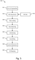
- FIG. 5 shows an example data flow for modulated CG-UCI symbol generation 500 in accordance with one embodiment, which may be used in combination with any of the embodiments described herein.
- the CG-UCI on the PUSCH may be configured by a CG for NOMA.
- the CG-UCI payload bits may be generated (step 501)
- the Cyclic Redundancy Check (CRC) parity bits may be generated (step 502)
- the bits of the CG-UCI payload may be attached with the CRC parity bits (step 503).
- the output bit sequence may be encoded by the Polar code (step 504) and rate matched to an output sequence with length E_tot (step 505).
- the rate matching output bit sequence may be interleaved by a triangular interleaver (step 506).
- the interleaving output sequence may be scrambled prior to modulation (step 507).
- the modulated symbols may be mapped to the resource for transmitting the CG-UCI (step 509).
- NOMA In grant-free NOMA, multiple UEs may perform UL transmission at the same time using the same configured grant resource. Accordingly, the system may be able to decode the CG-UCIs transmitted by multiple UEs at the same time. To improve the robustness of the CG-UCI transmission, NOMA UEs may transmit the CG-UCI using techniques including but not limited to the following:
- the DMRS here may refer to a DMRS port or a DMRS port with a certain initializer or certain cyclic shift.
- one group of UEs may be configured with the same DMRS port.
- the UEs configured with the same DMRS port may be configured with the same group ID N ID , CG ⁇ UCI Group .
- DMRS port 1 may be configured to group 1, group 2... group n where the DMRS sequence used by the UEs in the group 1, 2 ... n may be initialized by the group specific RNTI G-RNTI 1, G-RNTI 2, ..., G-RNTI n respectively.
- the UEs configured with the same DMRS port and the same initializer/cyclic shift may be configured with the same group ID N ID , CG ⁇ UCI Group .
- FIG. 6 shows an example data flow for modulated CG-UCI symbol generation with group specific scrambling 600 in accordance with one embodiment, which may be used in combination with any of the embodiments described herein.
- the CG-UCI payload bits may be generated (step 601), CRC parity bits may be generated (step 602), and then the bits of the CG-UCI payload may be attached with the CRC parity bits (step 603).
- the output bit sequence may be encoded by the Polar code (step 604) and rate matched to an output sequence with length E_tot (step 605).
- the rate matching output bit sequence may be interleaved by a triangular interleaver (step 606).
- the interleaving output sequence may be scrambled prior to modulation with group specific scrambling as described above (step 607). After the modulation (step 608), the modulated symbols may be mapped to the resource for transmitting the CG-UCI (step 609).
- the CG-UCIs transmitted by different UEs may be spread with different symbol level spreading codes.
- a UE may be configured with the spreading factor N SF,CG-UCI , and UE specific or group specific spreading code.
- the UE may use the cell ID to initialize the scrambling sequence generator and generate the scrambling sequence.
- a UE may be configured with the group ID N ID , CG ⁇ UCI Group to initialize the scrambling sequence generator and generate the scrambling sequence. After the modulation, the UE may apply the configured spreading code to spread the CG-UCI symbols to the configured resource.
- the DMRS here may refer to a DMRS port or a DMRS port with a certain initializer or a certain cyclic shift.
- one group of UEs may be configured with the same DMRS port.
- the UEs configured with same DMRS port may be configured with the same spreading code.
- multiple groups of UEs where different initializers or different cyclic shifts are configured to each group respectively may be configured with the same DMRS port.
- the UEs may be configured with the same DMRS port and the same initializer/cyclic shift may be configured with the same spreading code.
- FIG. 7 shows an example data flow for modulated CG-UCI symbol generation with symbol level spreading 700 in accordance with one embodiment, which may be used in combination with any of the embodiments described herein.
- the CG-UCI payload bits may be generated (step 701), the CRC parity bits may be generated (step 702), and then the bits of the CG-UCI payload may be attached with the CRC parity bits (step 703).
- the output bit sequence may be encoded by the Polar code (step 704) and rate matched to an output sequence with length E_tot (step 705).
- the rate matching output bit sequence may be interleaved by a triangular interleaver (step 706).
- the interleaving output sequence may be scrambled prior to symbol spreading (step 707).
- the scrambled output sequence may be modulated and spread with different symbol level spreading codes with a UE specific or group specific spreading code prior to modulation as described above (step 708).
- the spread symbols may be mapped to the resource for transmitting the CG-UCI (step 709).
- the CG-UCIs transmitted by different UEs may be interleaved by different bit level interleaver.
- the input bits of the block interleaver are denoted by e 0 , e 1 , e 2 , ... , e E-1 , where E is the number of the bits
- the output bit sequence may be derived as follows:
- the output of the block interleaver may be the bit sequence read out from the above matrix, column by column, starting with bit y 0 in row 0 of column 0 with skipping all the empty and NULL element.
- a UE may be configured with a UE specific or group specific interleaving offset n IL,offset to generate the output bit sequence of the block interleaver. With the configured interleaving offset n IL,offset , the UE may derive the output bit sequence of the block interleaver as follows:
- the proposed block interleaver scheme may be also expressed as follows:
- the UE may use the cell ID to initialize the scrambling sequence generator and generate the sequence to scramble the interleaved bit sequence.
- the UE may be configured with the group ID N ID , CG ⁇ UCI Group to initialize the scrambling sequence generator and generate the sequence to scramble the interleaved bit sequence.
- the DMRS here may refer to a DMRS port or a DMRS port with a certain initializer or a certain cyclic shift.
- one group of UEs may be configured with the same DMRS port.
- the UEs configured with same DMRS port may be configured with the same interleaving offset n IL,offset .
- multiple groups of UEs where different initializers or different cyclic shifts are configured to each group respectively may be configured with the same DMRS port.
- the UEs configured with the same DMRS port and the same initializer/cyclic shift may be configured with the same interleaving offset n IL,offset .
- FIG. 8 shows an example data flow for modulated CG-UCI symbol generation with bit level interleaving 800 in accordance with one embodiment, which may be used in combination with any of the embodiments described herein.
- the CG-UCI payload bits may be generated (step 801), the CRC parity bits may be generated (step 802), and then the bits of the CG-UCI payload may be attached with the CRC parity bits (step 803).
- the output bit sequence may be encoded by the Polar code (step 804) and rate matched to an output sequence with length E_tot (step 805).
- the rate matching output bit sequence may be interleaved by different bit level interleaver as described above (step 806).
- the interleaving output sequence may be scrambled prior to modulation (step 807). After the modulation (step 808), the modulated symbols may be mapped to the resource for transmitting the CG-UCI (step 809).
- Same symbols may be used by the UEs configured with the same configured grant to transmit the CG-UCI, the resources for different UEs may be frequency-division multiplexed (FDM-ed) or interlaced within the symbols.
- FDM-ed frequency-division multiplexed
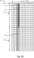
- FIG. 9A shows an example a diagram of an example of resources for transmitting a CG-UCI which are frequency-division multiplexed 900 in accordance with one embodiment, which may be used in combination with any of the embodiments described herein.
- FIG. 9A shows the RB k 901 and RB k + 1 902 in the frequency domain, and the slot n 903 in the time domain. Slot n 903 comprises 14 symbols 904 in the time domain.
- FIG. 9A shows REs for the DMRS for UE1 and the DMRS for UE2 912. In the example of FIG.
- the UE1 may map modulated CG-UCI symbols 911 to RB k + 1 902 in the frequency domain, and the UE2 may map modulated CG-UCI symbols 910 to RB k 901 in the frequency domain.
- a different DMRS may also be used by UE 1 and UE 2 in this example.
- the UE may be configured with the starting RB index and number of the allocated RBs.
- FIG. 9B shows an example a diagram of an example of resources for transmitting a CG-UCI in which the frequency resources configured for UEs may be interlaced at the RE level in accordance with one embodiment, which may be used in combination with any of the embodiments described herein.
- FIG. 9B shows the RB k 921 and RB k + 1 922 in the frequency domain, and the slot n 923 in the time domain. Slot n 923 comprises 14 symbols 924 in the time domain.
- FIG. 9B shows REs for the DMRS for UE1 and the DMRS for UE2 932. In the example of FIG.
- the UE1 may map modulated CG-UCI symbols 931 to RB k 921 and RB k + 1 922 in the frequency domain by interlacing at the RE level.
- the UE2 may map modulated CG-UCI symbols 930 to RB k 921 and RB k + 1 922 in the frequency domain by interlacing at the RE level.
- a different DMRS may also be used by UE 1 and UE 2 in this example.
- the interlacing may be at the block level where a block can be several REs, one RB, or several RBs.
- the UE may be configured with a group specific resource for CG-UCI transmitting.
- the UE may be configured with the size of the interlacing, e.g., number of REs; the total number of the interlacing; and the interlacing index or the offset value.
- the UE may determine the candidate interlacing patterns using the configured interlacing size and total interlacing number. Then, the UE may determine which interlacing to use based on the configured interlacing index or the offset value.
- the UE may generate the modulated CG-UCI symbols as shown in the example of FIG. 5 and may map the modulated CG-UCI symbols to the configured resources.
- a one to one association between the DMRS and the FDM-ed or interlaced resource for transmitting the CG-UCI may be used.
- the DMRS here may refer to a DMRS port or a DMRS port with a certain initializer or a certain cyclic shift.
- one group of UEs may be configured with the same DMRS port.
- the UEs configured with same DMRS port may be configured with the same FDM-ed or interlaced resource.
- multiple groups of UEs where different initializers or different cyclic shifts may be configured for each group, respectively, may be configured with the same DMRS port.
- the UEs configured with the same DMRS port and the same initializer/cyclic shift may be configured with the same FDM-ed or interlaced resource.
- a CG-UCI signature e.g., group ID N ID , CG ⁇ UCI Group ; spreading code; interleaving offset n IL,offset , may be configured for UE using techniques including but not limited to the following:
- a UE may be explicitly configured with the CG-UCI signature to be used for CG-UCI symbol generation through RRC configuration.
- the UE may be explicitly configured with the group ID N ID , CG ⁇ UCI Group , spreading code index or interleaving offset value n IL,offset .
- the CG-UCI signature may be configured through the UE specific RRC.
- the CG-UCI signature may be configured through the UE specific RRC configuration before the UE performs the transition from RRC-Connected state to RRC-Inactive state; or through broadcast message(s) on the common or shared channel at the RRC-Inactive state, i.e. carried on the shared channel PDSCH indicated by a DCI at the common search space scrambled by INACTIVE-RNTI for a group of UEs at RRC-Inactive state.
- Such a resource may be periodic in time (e.g., every N subframes or slots or symbols for non-slot based) with a certain duration (e.g. in M symbols or slots) and for each BWP (e.g., initial BWP, default BWP or active BWP configured or activated for Inactive state).
- a UE may be configured with the mapping between DMRS and CG-UCI signature through RRC configuration.
- the DMRS here may refer to a DMRS port or a DMRS port with a certain initializer or cyclic shift.
- the mapping may be a one to one association between the DMRS and CG-UCI signature.
- the UE may be configured with the mapping/association for multiple DMRS, e.g., for all the possible DMRS or for the DMRS within the configured DMRS pool for NOMA transmission.
- the UE may determine the CG-UCI signature to be used based on the configured mapping/association.
- the mapping/association may be configured through the UE specific RRC.
- the mapping/association may be configured through the UE specific RRC configuration before the UE performs the transition from RRC-Connected state to RRC-Inactive state; or through broadcasting message(s) on the common or shared channel at the RRC-Inactive state, i.e. carried on the shared channel PDSCH indicated by a DCI at the common search space scrambled by INACTIVE-RNTI for a group of UEs at RRC-Inactive state.
- the mapping/association may be configured through the broadcasting message, e.g., OSI, RMSI.
- a UE may be configured with the CG-UCI signature through RRC configuration and DCI signaling.
- the UE may be configured with CG-UCI signature pool through RRC configuration.
- the CG-UCI signature pool may contain m CG-UCI signatures, e.g., m interleaving offset values or m spreading sequences where each CG-UCI signature may have a signature index from 1 to m.
- a log 2 m bits DCI field CG-UCI signature indicator may be used to indicate the index of the CG-UCI signature to be used for the CG-UCI symbol generation.
- the CG-UCI may be transmitted on the PUCCH configured by a configured grant.
- a UE may be configured with a configured grant PUCCH for transmitting the CG-UCI through dedicated configuration.
- the configuration may be configured through RRC configuration, e.g., through RRC information element ConfiguredGrantPUCCHConfig. Or the configuration may be signalled by the DCI with CRC scrambled with CS-RNTI.
- the configuration may be configured through RRC configuration, e.g., through the UE specific RRC configuration before the UE performs the transition from RRC-Connected state to RRC-Inactive state; or through the broadcasting message on the common or shared channel at the RRC-Inactive state.
- the configuration may be signalled by a DCI at the common search space scrambled by INACTIVE-RNTI to a group of UEs at RRC-Inactive state.
- the configuration may be configured through the broadcasting message on the common or shared channel, e.g., through OSI or RMSI
- the configuration for the configured grant PUCCH may include parameters including but not limited to the following:
- the configured grant PUCCH may be activated once it is configured for UE and no further activation is needed.
- the configured grant PUCCH may be activated when a UE receives an activation DCI, e.g., the activation DCI with CRC scrambled with CS-RNTI for a UE in RRC-Connected state; or scrambled with INACTIVEGROUP-RNTI to a group of UEs at RRC-Inactive state. If the UE does not have data to be transmitted on the configured grant PUSCH, the UE may not transmit the CG-UCI on the configured grant PUCCH.
- the gNB may identify the UE using the received CG-UCI.
- the UE ID may be explicitly indicated in the CG-UCI payload bits in order to identify the UE.
- the UE may indicate its CS-RNTI in the CG-UCI payload bits.
- the UE may indicate its I-RNTI in the CG-UCI payload bits.
- the UE may indicate its International Mobile Subscriber Identity (IMSI) or Dynamic Mobile Subscriber Identity (DMSI) in the CG-UCI payload bits.
- IMSI International Mobile Subscriber Identity
- DMSI Dynamic Mobile Subscriber Identity
- the UE ID may be indicated jointly by two parts, e.g., the UE ID may be indicated by the CG-UCI payload bits and the DMRS jointly.
- the DMRS here may refer to a DMRS port or a DMRS port with a certain initializer or a cyclic shift.
- a group of UEs may be configured with the same DMRS.
- each UE may be configured with a local ID, e.g., L-RNTI.
- L-RNTI local ID
- the UE may use the configured DMRS and indicate the configured L-RNTI in the CG-UCI payload bits.
- the gNB may identify the UE by detecting the DMRS and decoding the L-RNTI from the CG-UCI.
- An UL transmission may use a configured grant with an adaptive MCS.
- a UE for example working in NOMA mode, may autonomously select the MCS value to be used and report it to the gNB through the CG-UCI, using techniques including but not limited to: (1) A UE may autonomously select its MCS value from the pre-specified or configured MCS table without being configured with a default MCS value. The UE may indicate the selected MCS value through the MCS indicator field bits in the CG-UCI. (a) A UE may autonomously select its MCS value from the entire MCS table and report the selected MCS value through the MCS indicator field in CG-UCI, e.g., 5 bits may be used for the MCS indicator field to indicate the selected MCS index I MCS .
- a UE may be configured with a subset of the entire MCS table.
- a UE may be configured with a starting MCS index I MCS,start and a length of the subset L MCS through the RRC configuration (the length of the subset L MCS may also be pre-specified).
- the UE may use ⁇ log 2 L MCS ⁇ bits to indicated index difference between the selected MCS index and the configured starting MCS index I MCS,start.
- the UE may autonomously select its MCS value from MCS index 10 to 13. If a UE selects the MCS value corresponding to the MCS index 12, the UE may indicate it by setting the MCS indicator field to be ⁇ 10' in the CG-UCI.
- Table 3 Example of MCS indicator field in CG-UCI alternative 1 Bit field UCI Content Function 00 Index difference between the selected MCS index and the configured starting MCS index I MCS,start is 0. MCS value corresponding to the MCS index I MCS,start is used. 01 Index difference between the selected MCS index and the configured starting MCS index I MCS,start is 1. MCS value corresponding to the MCS index I MCS,start + 1 is used.
- Index difference between the selected MCS index and the configured starting MCS index I MCS,start is 2. MCS value corresponding to the MCS index I MCS,start + 2 is used. 11 Index difference between the selected MCS index and the configured starting MCS index I MCS,start is 3. MCS value corresponding to the MCS index I MCS,start + 3 is used.
- the UE may autonomously select its MCS value for both the initial transmission and the retransmission.
- a UE may be configured with a default MCS value I MCS,default through RRC configuration (configured grant type 1) or through the activation DCI (configured grant type 2).
- the UE may autonomously decide if to overwrite the configured default MCS value.
- the UE may indicate it through the following alternatives:
- the UE may indicate the selected MCS value through the MCS indicator field bits in the CG-UCI.
- the selected MCS value may be indicated by the following alternatives:
- a UE may indicate that it selects the default MCS value through the MCS indicator field bits.
- the UE may use 1 most significant bit (MSB) bit in the MCS indicator field to indicate whether the selected MCS index is larger or smaller than the default MCS index, e.g., '0' indicates the selected MCS index is smaller than the default MCS index; '1' indicates the selected MCS index is larger than the default MCS index.
- MSB most significant bit
- the UE may use the rest 2 bits in the MCS indicator field to indicate the index difference between the selected MCS index and the configured default MCS index.
- An example of the MCS indicator field is shown in Table 4.
- the UE may indicate it by setting the MCS indicator field to be ⁇ 110' in the CG-UCI; if a UE selects the MCS value corresponding to the MCS index 7, the UE may indicate it by setting the MCS indicator field to be '011' in the CG-UCI.
- both '000' and '100' may explicitly indicate the UE selects to use the default MCS value.
- Table 4 Example of MCS indicator field in CG-UCI alternative 2 Bit field UCI Content Function 000 The select MCS index is smaller than the default MCS index and the index different is 0.
- MCS index I MCS,default is used 001
- the select MCS index is smaller than the default MCS index and the index different is 1.
- MCS index I MCS,default - 1 is used ... ... 011
- the select MCS index is smaller than the default MCS index and the index different is 3.
- MCS index I MCS,default - 3 is used 100
- the select MCS index is larger than the default MCS index and the index different is 0.
- MCS index I MCS,default is used 101
- the select MCS index is larger than the default MCS index and the index different is 1.
- MCS index I MCS,default + 1 is used ... ... 111
- the select MCS index is larger than the default MCS index and the index different is 3.
- MCS index I MCS,default + 3 is used
- a UE implicitly indicates that it selects the default MCS value, i.e., the UE may indicate that it selects the default MCS value by not including the MCS indicator bits in the CG-UCI.
- the UE may use 1 most significant bit (MSB) bit in the MCS indicator field to indicate whether the selected MCS index is larger or smaller than the default MCS index, e.g., '0' indicates the selected MCS index is smaller than the default MCS index; '1' indicates the selected MCS index is larger than the default MCS index.
- the UE may use the other 2 bits in the MCS indicator field to indicate the index difference between the selected MCS index and the configured default MCS index, where '00' indicates the index difference is 1; '01' indicates the index difference is 2, etc.
- An example of the MCS indicator field is shown in Table 5.
- Table 5 Example of MCS indicator field in CG-UCI alternative 3 Bit field UCI Content Function 000
- the select MCS index is smaller than the default MCS index and the index different is 1.
- MCS index I MCS,default - 1 is used 001
- the select MCS index is smaller than the default MCS index and the index different is 2.
- MCS index I MCS,default - 2 is used ... ... 011
- the select MCS index is smaller than the default MCS index and the index different is 4.
- MCS index I MCS,default - 4 is used 100
- the select MCS index is larger than the default MCS index and the index different is 1.
- MCS index I MCS,default + 1 is used 101
- the select MCS index is larger than the default MCS index and the index different is 2.
- MCS index I MCS,default + 2 is used ... ... 111
- the select MCS index is larger than the default MCS index and the index different is 4.
- MCS index I MCS,default + 4 is used
- the UE may use the default MCS value for the initial transmission. If the initial transmission is NACKed or the UE doesn't receive feedback within a timer, the UE may autonomously select its MCS value for retransmission. Or the UE may autonomously select if to overwrite the configured default MCS value for both the initial transmission and the retransmission.
- the 3rd Generation Partnership Project (3GPP) develops technical standards for cellular telecommunications network technologies, including radio access, the core transport network, and service capabilities - including work on codecs, security, and quality of service.
- Recent radio access technology (RAT) standards include WCDMA (commonly referred as 3G), LTE (commonly referred as 4G), and LTE-Advanced standards.
- 3GPP has begun working on the standardization of next generation cellular technology, called New Radio (NR), which is also referred to as "5G”.
- 3GPP NR standards development is expected to include the definition of next generation radio access technology (new RAT), which is expected to include the provision of new flexible radio access below 6 GHz, and the provision of new ultra-mobile broadband radio access above 6 GHz.
- new RAT next generation radio access technology
- the flexible radio access is expected to consist of a new, non-backwards compatible radio access in new spectrum below 6 GHz, and it is expected to include different operating modes that may be multiplexed together in the same spectrum to address a broad set of 3GPP NR use cases with diverging requirements.
- the ultra-mobile broadband is expected to include cmWave and mmWave spectrum that will provide the opportunity for ultra-mobile broadband access for, e.g., indoor applications and hotspots.
- the ultra-mobile broadband is expected to share a common design framework with the flexible radio access below 6 GHz, with cmWave and mmWave specific design optimizations.
- 3GPP has identified a variety of use cases that NR is expected to support, resulting in a wide variety of user experience requirements for data rate, latency, and mobility.
- the use cases include the following general categories: enhanced mobile broadband (e.g., broadband access in dense areas, indoor ultra-high broadband access, broadband access in a crowd, 50+ Mbps everywhere, ultra-low cost broadband access, mobile broadband in vehicles), critical communications, massive machine type communications, network operation (e.g., network slicing, routing, migration and interworking, energy savings), and enhanced vehicle-to-everything (eV2X) communications, which may include any of Vehicle-to-Vehicle Communication (V2V), Vehicle-to-Infrastructure Communication (V2I), Vehicle-to-Network Communication (V2N), Vehicle-to-Pedestrian Communication (V2P), and vehicle communications with other entitites.
- V2V Vehicle-to-Vehicle Communication
- V2I Vehicle-to-Infrastructure Communication
- V2N Vehicle-
- Specific service and applications in these categories include, e.g., monitoring and sensor networks, device remote controlling, bi-directional remote controlling, personal cloud computing, video streaming, wireless cloud-based office, first responder connectivity, automotive ecall, disaster alerts, real-time gaming, multi-person video calls, autonomous driving, augmented reality, tactile internet, and virtual reality to name a few. All of these use cases and others are contemplated herein.
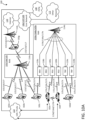
- FIG. 10A illustrates one embodiment of an example communications system 100 in which the methods and apparatuses described and claimed herein may be embodied.
- the example communications system 100 may include wireless transmit/receive units (WTRUs) 102a, 102b, 102c, 102d, 102e, 102f, and/or 102g (which generally or collectively may be referred to as WTRU 102), a radio access network (RAN) 103/104/105/103b/104b/105b, a core network 106/107/109, a public switched telephone network (PSTN) 108, the Internet 110, , other networks 112, and V2X server (or ProSe function and server) 113, though it will be appreciated that the disclosed embodiments contemplate any number of WTRUs, base stations, networks, and/or network elements.
- WTRUs wireless transmit/receive units
- Each of the WTRUs 102a, 102b, 102c, 102d, 102e, 102f, 102g may be any type of apparatus or device configured to operate and/or communicate in a wireless environment. Although each WTRU 102a, 102b, 102c, 102d, 102e, 102f, 102g is depicted in FIGs.
- each WTRU may comprise or be embodied in any type of apparatus or device configured to transmit and/or receive wireless signals, including, by way of example only, user equipment (UE), a mobile station, a fixed or mobile subscriber unit, a pager, a cellular telephone, a personal digital assistant (PDA), a smartphone, a laptop, a tablet, a netbook, a notebook computer, a personal computer, a wireless sensor, consumer electronics, a wearable device such as a smart watch or smart clothing, a medical or eHealth device, a robot, industrial equipment, a drone, a vehicle such as a car, truck, train, or airplane, and the like.
- UE user equipment
- PDA personal digital assistant
- smartphone a laptop, a tablet, a netbook, a notebook computer, a personal computer, a wireless sensor, consumer electronics, a wearable device such as a smart watch or smart clothing, a medical or eHealth device, a robot, industrial equipment, a drone, a vehicle such as a
- the communications system 100 may also include a base station 114a and a base station 114b.
- Base stations 114a may be any type of device configured to wirelessly interface with at least one of the WTRUs 102a, 102b, 102c to facilitate access to one or more communication networks, such as the core network 106/107/109, the Internet 110, and/or the other networks 112.
- Base stations 114b may be any type of device configured to wiredly and/or wirelessly interface with at least one of the RRHs (Remote Radio Heads) 118a, 118b, TRPs (Transmission and Reception Points) 119a, 119b, and/or RSUs (Roadside Units) 120a and 120b to facilitate access to one or more communication networks, such as the core network 106/107/109, the Internet 110, the other networks 112, and/or V2X server (or ProSe function and server) 113.
- RRHs Remote Radio Heads
- TRPs Transmission and Reception Points
- RSUs Raadside Units
- RRHs 118a, 118b may be any type of device configured to wirelessly interface with at least one of the WTRU 102c, to facilitate access to one or more communication networks, such as the core network 106/107/109, the Internet 110, and/or the other networks 112.
- TRPs 119a, 119b may be any type of device configured to wirelessly interface with at least one of the WTRU 102d, to facilitate access to one or more communication networks, such as the core network 106/107/109, the Internet 110, and/or the other networks 112.
- RSUs 120a and 120b may be any type of device configured to wirelessly interface with at least one of the WTRU 102e or 102f, to facilitate access to one or more communication networks, such as the core network 106/107/109, the Internet 110, the other networks 112, and/or V2X server (or ProSe function and server) 113.
- the base stations 114a, 114b may be a base transceiver station (BTS), a Node-B, an eNode B, a Home Node B, a Home eNode B, a site controller, an access point (AP), a wireless router, and the like. While the base stations 114a, 114b are each depicted as a single element, it will be appreciated that the base stations 114a, 114b may include any number of interconnected base stations and/or network elements.
- the base station 114a may be part of the RAN 103/104/105, which may also include other base stations and/or network elements (not shown), such as a base station controller (BSC), a radio network controller (RNC), relay nodes, etc.
- the base station 114b may be part of the RAN 103b/104b/105b, which may also include other base stations and/or network elements (not shown), such as a base station controller (BSC), a radio network controller (RNC), relay nodes, etc.
- the base station 114a may be configured to transmit and/or receive wireless signals within a particular geographic region, which may be referred to as a cell (not shown).
- the base station 114b may be configured to transmit and/or receive wired and/or wireless signals within a particular geographic region, which may be referred to as a cell (not shown).
- the cell may further be divided into cell sectors.
- the cell associated with the base station 114a may be divided into three sectors.
- the base station 114a may include three transceivers, e.g., one for each sector of the cell.
- the base station 114a may employ multiple-input multiple output (MIMO) technology and, therefore, may utilize multiple transceivers for each sector of the cell.
- MIMO multiple-input multiple output
- the base stations 114a may communicate with one or more of the WTRUs 102a, 102b, 102c over an air interface 115/116/117, which may be any suitable wireless communication link (e.g., radio frequency (RF), microwave, infrared (IR), ultraviolet (UV), visible light, cmWave, mmWave, etc.).
- the air interface 115/116/117 may be established using any suitable radio access technology (RAT).
- RAT radio access technology
- the base stations 114b may communicate with one or more of the RRHs 118a, 118b, TRPs 119a, 119b, and/or RSUs 120a and 120b, over a wired or air interface 115b/116b/117b, which may be any suitable wired (e.g., cable, optical fiber, etc.) or wireless communication link (e.g., radio frequency (RF), microwave, infrared (IR), ultraviolet (UV), visible light, cmWave, mmWave, etc.).
- the air interface 115b/116b/117b may be established using any suitable radio access technology (RAT).
- RAT radio access technology
- the RRHs 118a, 118b, TRPs 119a, 119b and/or RSUs 120a, 120b may communicate with one or more of the WTRUs 102c, 102d, 102e, 102f over an air interface 115c/116c/117c, which may be any suitable wireless communication link (e.g., radio frequency (RF), microwave, infrared (IR), ultraviolet (UV), visible light, cmWave, mmWave, etc.).
- the air interface 115c/116c/117c may be established using any suitable radio access technology (RAT).
- RAT radio access technology
- the WTRUs 102a, 102b, 102c,102d, 102e, 102f, and/or 102g may communicate with one another over an air interface 115d/116d/117d (not shown in the figures), which may be any suitable wireless communication link (e.g., radio frequency (RF), microwave, infrared (IR), ultraviolet (UV), visible light, cmWave, mmWave, etc.).
- the air interface 115d/116d/117d may be established using any suitable radio access technology (RAT).
- RAT radio access technology
- the communications system 100 may be a multiple access system and may employ one or more channel access schemes, such as CDMA, TDMA, FDMA, OFDMA, SC-FDMA, and the like.
- the base station 114a in the RAN 103/104/105 and the WTRUs 102a, 102b, 102c, or RRHs 118a, 118b,TRPs 119a, 119b and RSUs 120a, 120b, in the RAN 103b/104b/105b and the WTRUs 102c, 102d, 102e, 102f may implement a radio technology such as Universal Mobile Telecommunications System (UMTS) Terrestrial Radio Access (UTRA), which may establish the air interface 115/116/117 or 115c/116c/117c respectively using wideband CDMA (WCDMA).
- UMTS Universal Mobile Telecommunications System
- UTRA Universal Mobile Telecommunications System
- WCDMA wideband CDMA
- WCDMA may include communication protocols such as High-Speed Packet Access (HSPA) and/or Evolved HSPA (HSPA+).
- HSPA may include High-Speed Downlink Packet Access (HSDPA) and/or High-Speed Uplink Packet Access (HSUPA).
- HSPA High-Speed Packet Access
- HSDPA High-Speed Downlink Packet Access
- HSUPA High-Speed Uplink Packet Access
- the base station 114a and the WTRUs 102a, 102b, 102c, or RRHs 118a, 118b, TRPs 119a, 119b, and/or RSUs 120a, 120b, in the RAN 103b/104b/105b and the WTRUs 102c, 102d may implement a radio technology such as Evolved UMTS Terrestrial Radio Access (E-UTRA), which may establish the air interface 115/116/117 or 115c/116c/117c respectively using Long Term Evolution (LTE) and/or LTE-Advanced (LTE-A).
- LTE Long Term Evolution
- LTE-A LTE-Advanced
- the air interface 115/116/117 may implement 3GPP NR technology.
- the LTE and LTE-A technology includes LTE D2D and V2X technologies and interface (such as Sidelink communications and etc).
- the 3GPP NR technology includes NR V2X technologies and interface (such as Side
- the base station 114a in the RAN 103/104/105 and the WTRUs 102a, 102b, 102c, or RRHs 118a, 118b, TRPs 119a, 119b and/or RSUs 120a, 120b, in the RAN 103b/104b/105b and the WTRUs 102c, 102d, 102e, 102f may implement radio technologies such as IEEE 802.16 (e.g., Worldwide Interoperability for Microwave Access (WiMAX)), CDMA2000, CDMA2000 1X, CDMA2000 EV-DO, Interim Standard 2000 (IS-2000), Interim Standard 95 (IS-95), Interim Standard 856 (IS-856), Global System for Mobile communications (GSM), Enhanced Data rates for GSM Evolution (EDGE), GSM EDGE (GERAN), and the like.
- IEEE 802.16 e.g., Worldwide Interoperability for Microwave Access (WiMAX)
- the base station 114c in FIG. 10A may be a wireless router, Home Node B, Home eNode B, or access point, for example, and may utilize any suitable RAT for facilitating wireless connectivity in a localized area, such as a place of business, a home, a vehicle, a campus, and the like.
- the base station 114c and the WTRUs 102e may implement a radio technology such as IEEE 802.11 to establish a wireless local area network (WLAN).
- the base station 114c and the WTRUs 102d may implement a radio technology such as IEEE 802.15 to establish a wireless personal area network (WPAN).
- WLAN wireless local area network
- WPAN wireless personal area network
- the base station 114c and the WTRUs 102e may utilize a cellular-based RAT (e.g., WCDMA, CDMA2000, GSM, LTE, LTE-A, etc.) to establish a picocell or femtocell.
- a cellular-based RAT e.g., WCDMA, CDMA2000, GSM, LTE, LTE-A, etc.
- the base station 114b may have a direct connection to the Internet 110.
- the base station 114c may not be required to access the Internet 110 via the core network 106/107/109.
- the RAN 103/104/105 and/or RAN 103b/104b/105b may be in communication with the core network 106/107/109, which may be any type of network configured to provide voice, data, applications, and/or voice over internet protocol (VoIP) services to one or more of the WTRUs 102a, 102b, 102c, 102d.
- the core network 106/107/109 may provide call control, billing services, mobile location-based services, pre-paid calling, Internet connectivity, video distribution, etc., and/or perform high-level security functions, such as user authentication.
- the RAN 103/104/105 and/or RAN 103b/104b/105b and/or the core network 106/107/109 may be in direct or indirect communication with other RANs that employ the same RAT as the RAN 103/104/105 and/or RAN 103b/104b/105b or a different RAT.
- the core network 106/107/109 may also be in communication with another RAN (not shown) employing a GSM radio technology.
- the core network 106/107/109 may also serve as a gateway for the WTRUs 102a, 102b, 102c, 102d, 102e to access the PSTN 108, the Internet 110, and/or other networks 112.
- the PSTN 108 may include circuit-switched telephone networks that provide plain old telephone service (POTS).
- POTS plain old telephone service
- the Internet 110 may include a global system of interconnected computer networks and devices that use common communication protocols, such as the transmission control protocol (TCP), user datagram protocol (UDP) and the internet protocol (IP) in the TCP/IP internet protocol suite.
- the networks 112 may include wired or wireless communications networks owned and/or operated by other service providers.
- the networks 112 may include another core network connected to one or more RANs, which may employ the same RAT as the RAN 103/104/105 and/or RAN 103b/104b/105b or a different RAT.
- Some or all of the WTRUs 102a, 102b, 102c, 102d in the communications system 100 may include multi-mode capabilities, e.g., the WTRUs 102a, 102b, 102c, 102d, and 102e may include multiple transceivers for communicating with different wireless networks over different wireless links.
- the WTRU 102e shown in FIG. 10A may be configured to communicate with the base station 114a, which may employ a cellular-based radio technology, and with the base station 114c, which may employ an IEEE 802 radio technology.
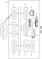
- FIG. 10B is a block diagram of an example apparatus or device configured for wireless communications in accordance with the embodiments illustrated herein, such as for example, a WTRU 102.
- the example WTRU 102 may include a processor 118, a transceiver 120, a transmit/receive element 122, a speaker/microphone 124, a keypad 126, a display/touchpad/indicators 128, non-removable memory 130, removable memory 132, a power source 134, a global positioning system (GPS) chipset 136, and other peripherals 138.
- GPS global positioning system
- the base stations 114a and 114b, and/or the nodes that base stations 114a and 114b may represent, such as but not limited to transceiver station (BTS), a Node-B, a site controller, an access point (AP), a home node-B, an evolved home node-B (eNodeB), a home evolved node-B (HeNB), a home evolved node-B gateway, and proxy nodes, among others, may include some or all of the elements depicted in FIG. 10B and described herein.
- BTS transceiver station
- Node-B a Node-B
- AP access point
- eNodeB evolved home node-B
- HeNB home evolved node-B gateway
- proxy nodes among others, may include some or all of the elements depicted in FIG. 10B and described herein.
- the processor 118 may be a general purpose processor, a special purpose processor, a conventional processor, a digital signal processor (DSP), a plurality of microprocessors, one or more microprocessors in association with a DSP core, a controller, a microcontroller, Application Specific Integrated Circuits (ASICs), Field Programmable Gate Array (FPGAs) circuits, any other type of integrated circuit (IC), a state machine, and the like.
- the processor 118 may perform signal coding, data processing, power control, input/output processing, and/or any other functionality that enables the WTRU 102 to operate in a wireless environment.
- the processor 118 may be coupled to the transceiver 120, which may be coupled to the transmit/receive element 122. While FIG. 10B depicts the processor 118 and the transceiver 120 as separate components, it will be appreciated that the processor 118 and the transceiver 120 may be integrated together in an electronic package or chip.
- the transmit/receive element 122 may be configured to transmit signals to, or receive signals from, a base station (e.g., the base station 114a) over the air interface 115/116/117.
- a base station e.g., the base station 114a
- the transmit/receive element 122 may be an antenna configured to transmit and/or receive RF signals.
- the transmit/receive element 122 may be an emitter/detector configured to transmit and/or receive IR, UV, or visible light signals, for example.
- the transmit/receive element 122 may be configured to transmit and receive both RF and light signals. It will be appreciated that the transmit/receive element 122 may be configured to transmit and/or receive any combination of wireless signals.
- the WTRU 102 may include any number of transmit/receive elements 122. More specifically, the WTRU 102 may employ MIMO technology. Thus, in an embodiment, the WTRU 102 may include two or more transmit/receive elements 122 (e.g., multiple antennas) for transmitting and receiving wireless signals over the air interface 115/116/117.
- the WTRU 102 may include two or more transmit/receive elements 122 (e.g., multiple antennas) for transmitting and receiving wireless signals over the air interface 115/116/117.
- the transceiver 120 may be configured to modulate the signals that are to be transmitted by the transmit/receive element 122 and to demodulate the signals that are received by the transmit/receive element 122.
- the WTRU 102 may have multi-mode capabilities.
- the transceiver 120 may include multiple transceivers for enabling the WTRU 102 to communicate via multiple RATs, such as UTRA and IEEE 802.11, for example.
- the processor 118 of the WTRU 102 may be coupled to, and may receive user input data from, the speaker/microphone 124, the keypad 126, and/or the display/touchpad/indicators 128 (e.g., a liquid crystal display (LCD) display unit or organic light-emitting diode (OLED) display unit).
- the processor 118 may also output user data to the speaker/microphone 124, the keypad 126, and/or the display/touchpad/indicators 128.
- the processor 118 may access information from, and store data in, any type of suitable memory, such as the non-removable memory 130 and/or the removable memory 132.
- the non-removable memory 130 may include random-access memory (RAM), read-only memory (ROM), a hard disk, or any other type of memory storage device.
- the removable memory 132 may include a subscriber identity module (SIM) card, a memory stick, a secure digital (SD) memory card, and the like.
- SIM subscriber identity module
- SD secure digital
- the processor 118 may access information from, and store data in, memory that is not physically located on the WTRU 102, such as on a server or a home computer (not shown).
- the processor 118 may receive power from the power source 134, and may be configured to distribute and/or control the power to the other components in the WTRU 102.
- the power source 134 may be any suitable device for powering the WTRU 102.
- the power source 134 may include one or more dry cell batteries, solar cells, fuel cells, and the like.
- the processor 118 may also be coupled to the GPS chipset 136, which may be configured to provide location information (e.g., longitude and latitude) regarding the current location of the WTRU 102.
- location information e.g., longitude and latitude
- the WTRU 102 may receive location information over the air interface 115/116/117 from a base station (e.g., base stations 114a, 114b) and/or determine its location based on the timing of the signals being received from two or more nearby base stations. It will be appreciated that the WTRU 102 may acquire location information by way of any suitable location-determination method while remaining consistent with an embodiment.
- the processor 118 may further be coupled to other peripherals 138, which may include one or more software and/or hardware modules that provide additional features, functionality and/or wired or wireless connectivity.
- the peripherals 138 may include various sensors such as an accelerometer, biometrics (e.g., finger print) sensors, an e-compass, a satellite transceiver, a digital camera (for photographs or video), a universal serial bus (USB) port or other interconnect interfaces, a vibration device, a television transceiver, a hands free headset, a Bluetooth ® module, a frequency modulated (FM) radio unit, a digital music player, a media player, a video game player module, an Internet browser, and the like.
- biometrics e.g., finger print
- a satellite transceiver for photographs or video
- USB universal serial bus
- FM frequency modulated
- the WTRU 102 may be embodied in other apparatuses or devices, such as a sensor, consumer electronics, a wearable device such as a smart watch or smart clothing, a medical or eHealth device, a robot, industrial equipment, a drone, a vehicle such as a car, truck, train, or airplane.
- the WTRU 102 may connect to other components, modules, or systems of such apparatuses or devices via one or more interconnect interfaces, such as an interconnect interface that may comprise one of the peripherals 138.
- FIG. 10C is a system diagram of the RAN 103 and the core network 106 according to an embodiment.
- the RAN 103 may employ a UTRA radio technology to communicate with the WTRUs 102a, 102b, and 102c over the air interface 115.
- the RAN 103 may also be in communication with the core network 106.
- the RAN 103 may include Node-Bs 140a, 140b, 140c, which may each include one or more transceivers for communicating with the WTRUs 102a, 102b, 102c over the air interface 115.
- the Node-Bs 140a, 140b, 140c may each be associated with a particular cell (not shown) within the RAN 103.
- the RAN 103 may also include RNCs 142a, 142b. It will be appreciated that the RAN 103 may include any number of Node-Bs and RNCs while remaining consistent with an embodiment.
- the Node-Bs 140a, 140b may be in communication with the RNC 142a. Additionally, the Node-B 140c may be in communication with the RNC 142b.
- the Node-Bs 140a, 140b, 140c may communicate with the respective RNCs 142a, 142b via an Iub interface.
- the RNCs 142a, 142b may be in communication with one another via an Iur interface.
- Each of the RNCs 142a, 142b may be configured to control the respective Node-Bs 140a, 140b, 140c to which it is connected.
- each of the RNCs 142a, 142b may be configured to carry out or support other functionality, such as outer loop power control, load control, admission control, packet scheduling, handover control, macro-diversity, security functions, data encryption, and the like.
- the core network 106 shown in FIG. 10C may include a media gateway (MGW) 144, a mobile switching center (MSC) 146, a serving GPRS support node (SGSN) 148, and/or a gateway GPRS support node (GGSN) 150. While each of the foregoing elements are depicted as part of the core network 106, it will be appreciated that any one of these elements may be owned and/or operated by an entity other than the core network operator.
- MGW media gateway
- MSC mobile switching center
- SGSN serving GPRS support node
- GGSN gateway GPRS support node
- the RNC 142a in the RAN 103 may be connected to the MSC 146 in the core network 106 via an IuCS interface.
- the MSC 146 may be connected to the MGW 144.
- the MSC 146 and the MGW 144 may provide the WTRUs 102a, 102b, 102c with access to circuit-switched networks, such as the PSTN 108, to facilitate communications between the WTRUs 102a, 102b, 102c and traditional land-line communications devices.
- the RNC 142a in the RAN 103 may also be connected to the SGSN 148 in the core network 106 via an IuPS interface.
- the SGSN 148 may be connected to the GGSN 150.
- the SGSN 148 and the GGSN 150 may provide the WTRUs 102a, 102b, 102c with access to packet-switched networks, such as the Internet 110, to facilitate communications between and the WTRUs 102a, 102b, 102c and IP-enabled devices.
- the core network 106 may also be connected to the networks 112, which may include other wired or wireless networks that are owned and/or operated by other service providers.
- FIG. 10D is a system diagram of the RAN 104 and the core network 107 according to an embodiment.
- the RAN 104 may employ an E-UTRA radio technology to communicate with the WTRUs 102a, 102b, and 102c over the air interface 116.
- the RAN 104 may also be in communication with the core network 107.
- the RAN 104 may include eNode-Bs 160a, 160b, 160c, though it will be appreciated that the RAN 104 may include any number of eNode-Bs while remaining consistent with an embodiment.
- the eNode-Bs 160a, 160b, 160c may each include one or more transceivers for communicating with the WTRUs 102a, 102b, 102c over the air interface 116.
- the eNode-Bs 160a, 160b, 160c may implement MIMO technology.
- the eNode-B 160a for example, may use multiple antennas to transmit wireless signals to, and receive wireless signals from, the WTRU 102a.
- Each of the eNode-Bs 160a, 160b, and 160c may be associated with a particular cell (not shown) and may be configured to handle radio resource management decisions, handover decisions, scheduling of users in the uplink and/or downlink, and the like. As shown in FIG. 10D , the eNode-Bs 160a, 160b, 160c may communicate with one another over an X2 interface.
- the core network 107 shown in FIG. 10D may include a mobility management gateway (MME) 162, a serving gateway 164, and a packet data network (PDN) gateway 166. While each of the foregoing elements are depicted as part of the core network 107, it will be appreciated that any one of these elements may be owned and/or operated by an entity other than the core network operator.
- MME mobility management gateway
- PDN packet data network
- the MME 162 may be connected to each of the eNode-Bs 160a, 160b, and 160c in the RAN 104 via an S1 interface and may serve as a control node.
- the MME 162 may be responsible for authenticating users of the WTRUs 102a, 102b, 102c, bearer activation/deactivation, selecting a particular serving gateway during an initial attach of the WTRUs 102a, 102b, 102c, and the like.
- the MME 162 may also provide a control plane function for switching between the RAN 104 and other RANs (not shown) that employ other radio technologies, such as GSM or WCDMA.
- the serving gateway 164 may be connected to each of the eNode-Bs 160a, 160b, and 160c in the RAN 104 via the S1 interface.
- the serving gateway 164 may generally route and forward user data packets to/from the WTRUs 102a, 102b, 102c.
- the serving gateway 164 may also perform other functions, such as anchoring user planes during inter-eNode B handovers, triggering paging when downlink data is available for the WTRUs 102a, 102b, 102c, managing and storing contexts of the WTRUs 102a, 102b, 102c, and the like.
- the serving gateway 164 may also be connected to the PDN gateway 166, which may provide the WTRUs 102a, 102b, 102c with access to packet-switched networks, such as the Internet 110, to facilitate communications between the WTRUs 102a, 102b, 102c and IP-enabled devices.
- the PDN gateway 166 may provide the WTRUs 102a, 102b, 102c with access to packet-switched networks, such as the Internet 110, to facilitate communications between the WTRUs 102a, 102b, 102c and IP-enabled devices.
- the core network 107 may facilitate communications with other networks.
- the core network 107 may provide the WTRUs 102a, 102b, 102c with access to circuit-switched networks, such as the PSTN 108, to facilitate communications between the WTRUs 102a, 102b, 102c and traditional land-line communications devices.
- the core network 107 may include, or may communicate with, an IP gateway (e.g., an IP multimedia subsystem (IMS) server) that serves as an interface between the core network 107 and the PSTN 108.
- IMS IP multimedia subsystem
- the core network 107 may provide the WTRUs 102a, 102b, 102c with access to the networks 112, which may include other wired or wireless networks that are owned and/or operated by other service providers.
- FIG. 10E is a system diagram of the RAN 105 and the core network 109 according to an embodiment.
- the RAN 105 may be an access service network (ASN) that employs IEEE 802.16 radio technology to communicate with the WTRUs 102a, 102b, and 102c over the air interface 117.
- ASN access service network
- the communication links between the different functional entities of the WTRUs 102a, 102b, 102c, the RAN 105, and the core network 109 may be defined as reference points.
- the RAN 105 may include base stations 180a, 180b, 180c, and an ASN gateway 182, though it will be appreciated that the RAN 105 may include any number of base stations and ASN gateways while remaining consistent with an embodiment.
- the base stations 180a, 180b, 180c may each be associated with a particular cell in the RAN 105 and may include one or more transceivers for communicating with the WTRUs 102a, 102b, 102c over the air interface 117.
- the base stations 180a, 180b, 180c may implement MIMO technology.
- the base station 180a for example, may use multiple antennas to transmit wireless signals to, and receive wireless signals from, the WTRU 102a.
- the base stations 180a, 180b, 180c may also provide mobility management functions, such as handoff triggering, tunnel establishment, radio resource management, traffic classification, quality of service (QoS) policy enforcement, and the like.
- the ASN gateway 182 may serve as a traffic aggregation point and may be responsible for paging, caching of subscriber profiles, routing to the core network 109, and the like.
- the air interface 117 between the WTRUs 102a, 102b, 102c and the RAN 105 may be defined as an R1 reference point that implements the IEEE 802.16 specification.
- each of the WTRUs 102a, 102b, and 102c may establish a logical interface (not shown) with the core network 109.
- the logical interface between the WTRUs 102a, 102b, 102c and the core network 109 may be defined as an R2 reference point, which may be used for authentication, authorization, IP host configuration management, and/or mobility management.
- the communication link between each of the base stations 180a, 180b, and 180c may be defined as an R8 reference point that includes protocols for facilitating WTRU handovers and the transfer of data between base stations.
- the communication link between the base stations 180a, 180b, 180c and the ASN gateway 182 may be defined as an R6 reference point.
- the R6 reference point may include protocols for facilitating mobility management based on mobility events associated with each of the WTRUs 102a, 102b, 102c.
- the RAN 105 may be connected to the core network 109.
- the communication link between the RAN 105 and the core network 109 may defined as an R3 reference point that includes protocols for facilitating data transfer and mobility management capabilities, for example.
- the core network 109 may include a mobile IP home agent (MIP-HA) 184, an authentication, authorization, accounting (AAA) server 186, and a gateway 188. While each of the foregoing elements are depicted as part of the core network 109, it will be appreciated that any one of these elements may be owned and/or operated by an entity other than the core network operator.
- MIP-HA mobile IP home agent
- AAA authentication, authorization, accounting
- the MIP-HA may be responsible for IP address management, and may enable the WTRUs 102a, 102b, and 102c to roam between different ASNs and/or different core networks.
- the MIP-HA 184 may provide the WTRUs 102a, 102b, 102c with access to packet-switched networks, such as the Internet 110, to facilitate communications between the WTRUs 102a, 102b, 102c and IP-enabled devices.
- the AAA server 186 may be responsible for user authentication and for supporting user services.
- the gateway 188 may facilitate interworking with other networks.
- the gateway 188 may provide the WTRUs 102a, 102b, 102c with access to circuit-switched networks, such as the PSTN 108, to facilitate communications between the WTRUs 102a, 102b, 102c and traditional land-line communications devices.
- the gateway 188 may provide the WTRUs 102a, 102b, 102c with access to the networks 112, which may include other wired or wireless networks that are owned and/or operated by other service providers.
- the RAN 105 may be connected to other ASNs and the core network 109 may be connected to other core networks.
- the communication link between the RAN 105 the other ASNs may be defined as an R4 reference point, which may include protocols for coordinating the mobility of the WTRUs 102a, 102b, 102c between the RAN 105 and the other ASNs.
- the communication link between the core network 109 and the other core networks may be defined as an R5 reference, which may include protocols for facilitating interworking between home core networks and visited core networks.
- the core network entities described herein and illustrated in FIGs. 10A , 10C , 10D , and 10E are identified by the names given to those entities in certain existing 3GPP specifications, but it is understood that in the future those entities and functionalities may be identified by other names and certain entities or functions may be combined in future specifications published by 3GPP, including future 3GPP NR specifications.
- the particular network entities and functionalities described and illustrated in FIGs. 10A , 10B , 10C , 10D , and 10E are provided by way of example only, and it is understood that the subject matter disclosed and claimed herein may be embodied or implemented in any similar communication system, whether presently defined or defined in the future.
- FIG. 10F is a block diagram of an exemplary computing system 90 in which one or more apparatuses of the communications networks illustrated in FIGs. 10A , 10C , 10D and 10E may be embodied, such as certain nodes or functional entities in the RAN 103/104/105, Core Network 106/107/109, PSTN 108, Internet 110, or Other Networks 112.
- Computing system 90 may comprise a computer or server and may be controlled primarily by computer readable instructions, which may be in the form of software, wherever, or by whatever means such software is stored or accessed. Such computer readable instructions may be executed within a processor 91, to cause computing system 90 to do work.
- the processor 91 may be a general purpose processor, a special purpose processor, a conventional processor, a digital signal processor (DSP), a plurality of microprocessors, one or more microprocessors in association with a DSP core, a controller, a microcontroller, Application Specific Integrated Circuits (ASICs), Field Programmable Gate Array (FPGAs) circuits, any other type of integrated circuit (IC), a state machine, and the like.
- the processor 91 may perform signal coding, data processing, power control, input/output processing, and/or any other functionality that enables the computing system 90 to operate in a communications network.
- Coprocessor 81 is an optional processor, distinct from main processor 91, that may perform additional functions or assist processor 91. Processor 91 and/or coprocessor 81 may receive, generate, and process data related to the methods and apparatuses disclosed herein.
- processor 91 fetches, decodes, and executes instructions, and transfers information to and from other resources via the computing system's main data-transfer path, system bus 80.
- system bus 80 Such a system bus connects the components in computing system 90 and defines the medium for data exchange.
- System bus 80 typically includes data lines for sending data, address lines for sending addresses, and control lines for sending interrupts and for operating the system bus.
- An example of such a system bus 80 is the PCI (Peripheral Component Interconnect) bus.
- RAM random access memory
- ROM read only memory
- Such memories include circuitry that allows information to be stored and retrieved.
- ROMs 93 generally contain stored data that cannot easily be modified. Data stored in RAM 82 may be read or changed by processor 91 or other hardware devices. Access to RAM 82 and/or ROM 93 may be controlled by memory controller 92.
- Memory controller 92 may provide an address translation function that translates virtual addresses into physical addresses as instructions are executed. Memory controller 92 may also provide a memory protection function that isolates processes within the system and isolates system processes from user processes. Thus, a program running in a first mode may access only memory mapped by its own process virtual address space; it cannot access memory within another process's virtual address space unless memory sharing between the processes has been set up.
- computing system 90 may contain peripherals controller 83 responsible for communicating instructions from processor 91 to peripherals, such as printer 94, keyboard 84, mouse 95, and disk drive 85.
- peripherals controller 83 responsible for communicating instructions from processor 91 to peripherals, such as printer 94, keyboard 84, mouse 95, and disk drive 85.
- Display 86 which is controlled by display controller 96, is used to display visual output generated by computing system 90. Such visual output may include text, graphics, animated graphics, and video. The visual output may be provided in the form of a graphical user interface (GUI).
- GUI graphical user interface
- Display 86 may be implemented with a CRT-based video display, an LCD-based flat-panel display, gas plasma-based flat-panel display, or a touch-panel.
- Display controller 96 includes electronic components required to generate a video signal that is sent to display 86.
- computing system 90 may contain communication circuitry, such as for example a network adapter 97, that may be used to connect computing system 90 to an external communications network, such as the RAN 103/104/105, Core Network 106/107/109, PSTN 108, Internet 110, or Other Networks 112 of FIGs. 10A , 10B , 10C , 10D , and 10E , to enable the computing system 90 to communicate with other nodes or functional entities of those networks.
- the communication circuitry alone or in combination with the processor 91, may be used to perform the transmitting and receiving steps of certain apparatuses, nodes, or functional entities described herein.
- FIG. 10G illustrates one embodiment of an example communications system 111 in which the methods and apparatuses described and claimed herein may be embodied.
- the example communications system 111 may include wireless transmit/receive units (WTRUs) A, B, C, D, E, F, a base station, a V2X server, and a RSUs A and B, though it will be appreciated that the disclosed embodiments contemplate any number of WTRUs, base stations, networks, and/or network elements.
- WTRUs wireless transmit/receive units
- A, B, C, D, E can be out of range of the network (for example, in the figure out of the cell coverage boundary shown as the dash line).
- WTRUs A, B, C form a V2X group, among which WTRU A is the group lead and WTRUs B and C are group members.
- WTRUs A, B, C, D, E, F may communicate over Uu interface or Sidelink (PC5) interface.
- any or all of the apparatuses, systems, methods and processes described herein may be embodied in the form of computer executable instructions (e.g., program code) stored on a computer-readable storage medium which instructions, when executed by a processor, such as processors 118 or 91, cause the processor to perform and/or implement the systems, methods and processes described herein.
- a processor such as processors 118 or 91
- any of the steps, operations or functions described herein may be implemented in the form of such computer executable instructions, executing on the processor of an apparatus or computing system configured for wireless and/or wired network communications.
- Computer readable storage media include volatile and nonvolatile, removable and non-removable media implemented in any non-transitory (e.g., tangible or physical) method or technology for storage of information, but such computer readable storage media do not includes signals.
- Computer readable storage media include, but are not limited to, RAM, ROM, EEPROM, flash memory or other memory technology, CD-ROM, digital versatile disks (DVD) or other optical disk storage, magnetic cassettes, magnetic tape, magnetic disk storage or other magnetic storage devices, or any other tangible or physical medium which may be used to store the desired information and which may be accessed by a computing system.
Landscapes
- Engineering & Computer Science (AREA)
- Signal Processing (AREA)
- Computer Networks & Wireless Communication (AREA)
- Quality & Reliability (AREA)
- Mobile Radio Communication Systems (AREA)
Description
- Several use cases have been proposed for non-orthogonal multiple access (NOMA) in 5G NR. In grant-free NOMA, a gNB may not know when a UE is to perform an UL transmission or may not know the identity of the UE. In a grant-based scenario, the UE may be configured with dedicated demodulation reference signal (DMRS), so that the gNB may identify the UE by detecting the corresponding DMRS. Further, in grant-free transmissions, an adaptive modulation and coding scheme (MCS), in which a UE may autonomously select its MCS value, may be beneficial to improve the spectral efficiency. In this case, the gNB may need to be notified of the MCS level used by the UE to decode the data.
- Accordingly, there is a need for mechanisms for UE identification in grant-free NOMA and mechanisms for MCS selection and reporting.
- 3GPP document R1-1806533 (May 21st - 25th, 2018) entitled "NOMA related procedure" discusses grant free UL NOMA related procedures.
- The invention is defined by the claims.
- The foregoing Summary, as well as the following Detailed Description, is better understood when read in conjunction with the appended drawings. In order to illustrate the present disclosure, various aspects of the disclosure are shown. However, the disclosure is not limited to the specific aspects discussed. In the drawings:
-
FIG. 1 is a diagram of a non-orthogonal multiple access (NOMA) scheme; -
FIG. 2A is a diagram of an example of a configured grant with PUSCH mapping type A; -
FIG. 2B is a diagram of an example of a configured grant with PUSCH mapping type B; -
FIG. 3A is a diagram of an example of a CG-UCI transmitted on the PUSCH after the front loaded DMRS symbol for a configured grant with PUSCH mapping type A; -
FIG. 3B is a diagram of an example of a CG-UCI transmitted on the PUSCH after the front loaded DMRS symbol for a configured grant with PUSCH mapping type B; -
FIG. 4A is a diagram of an example of a CG-UCI transmitted on the PUSCH before the front loaded DMRS symbol for a configured grant starting from the first symbol of the PUSCH; -
FIG. 4B is a diagram of an example of a CG-UCI transmitted on the PUSCH before the front loaded DMRS symbol for a configured grant CG-UCI transmitted on the symbol adjacent to the front loaded DMRS symbol; -
FIG. 5 is a diagram of an example of a data flow for a CG-UCI symbol generation; -
FIG. 6 is a diagram of an example of a data flow for a CG-UCI symbol generation with group specific scrambling; -
FIG. 7 is a diagram of an example data flow for a CG-UCI symbol generation with symbol level spreading; -
FIG. 8 is a diagram of an example data flow for a CG-UCI symbol generation with bit-level interleaving; -
FIG. 9A is a diagram of an example of resources for transmitting a CG-UCI which are frequency-division multiplexed; -
FIG. 9B is a diagram of an example of resources for transmitting a CG-UCI which are interlaced; -
FIG 10A illustrates one embodiment of an example communications system in which the methods and apparatuses described and claimed herein may be embodied; -
FIG. 10B is a block diagram of an example apparatus or device configured for wireless communications in accordance with the embodiments illustrated herein; -
FIG. 10C is a system diagram of a RAN and core network according to an embodiment; -
FIG. 10D is a system diagram of a RAN and core network according to an embodiment; -
FIG. 10E is a system diagram of a RAN and core network according to an embodiment; -
FIG. 10F is a block diagram of an exemplary computing system in which one or more apparatuses of the communications networks illustrated inFIGs. 10A ,10C ,10D and10E may be embodied; and -
FIG. 10G illustrates one embodiment of an example communications system in which the methods and apparatuses described and claimed herein may be embodied. - Methods and apparatuses are described herein for uplink control information (UCI) design for uplink (UL) transmission with configured grants.
- The following abbreviations and definitions may be used herein:
- ACK
- Acknowledgement
- BWP
- Bandwidth Part
- CDM
- Code-Domain Multiplexing
- CE
- Control Element
- CG
- Configured Grant
- CSI
- Channel State Information
- CS-RNTI
- Configured Scheduling RNTI
- DCI
- Downlink Control Information
- DL
- Downlink
- DMRS
- Demodulation Reference Signal
- DMSI
- Dynamic Mobile Subscriber Identity
- eMBB
- enhanced Mobile Broadband
- FDM
- Frequency-Division Multiplexing
- HARQ
- Hybrid Automatic Repeat Request
- IMSI
- International Mobile Subscriber Identity
- KPI
- Key Performance Indicators
- LTE
- Long Term Evolution
- MAC
- Medium Access Control
- MCS
- Modulation Coding Scheme
- mMTC
- massive Machine Type Communication
- MSB
- Most Significant Bit
- NOMA
- Non-Orthogonal Multiple Access
- NR
- New Radio
- OFDM
- Orthogonal Frequency-Division Multiplexing
- OMA
- Orthogonal Multiple Access
- OSI
- Other System Information
- PDCCH
- Physical Downlink Control Channel
- PUSCH
- Physical Uplink Shared Data Channel
- PTRS
- Phase Tracking Reference Signal
- QAM
- Quadrature Amplitude Modulation
- QoS
- Quality of Service
- QPSK
- Quadrature Phase-Shift Keying
- RE
- Resource Element
- RMSI
- Remain Minimum System Information
- RNTI
- Radio Network Temporary Identifier
- RRC
- Radio Resource Control
- TDM
- Time-Division Multiplexing
- UE
- User Equipment
- UL
- Uplink
- URLLC
- Ultra-Reliable and Low Latency Communications
- Long Term Evolution (LTE) systems may use non-orthogonal multiple access (NOMA). The first NOMA application in LTE was introduced for the downlink (DL). The DL NOMA was proposed, and then the necessary mechanisms were investigated to enable LTE to support DL intra-cell multiuser superposition transmission (MUST) for data channels with assistance information from a serving Base Station (BS) to a user equipment (UE) with respect to whether it experienced intra-cell interference. NOMA has also been discussed for use in 5G NR. In the
NR NOMA phase 1 study, numerous NOMA schemes have been proposed, mainly targeting uplink (UL) transmissions to support massive connectivity. -
FIG. 1 shows anexample NOMA scheme 100.FIG. 1 shows, for multiple UEs, the givenfrequency 51,time 53, and the code/sequence/interleaver 52. As shown in the example ofFIG. 1 ,UEs time 55 and frequency (bandwidth (BW)) 54 resource when operating in a NOMA scheme. There may be significant benefits of NOMA in terms of UL link-level sum throughput and overloading capability, as well as system capacity enhancement in terms of supported packet arrival rate at given system outage. - However, when communicating using a NOMA scheme, there may be interference between transmissions using overlapping resources such as the overlapping resources being used by
UEs FIG. 1 . As the system load increases, i.e. more NOMA UEs share or overlap the resources, this non-orthogonal characteristic (interference between transmissions) may be more pronounced. To combat the interference between non-orthogonal transmissions, transmitter side schemes such as spreading (linear or non-linear, with or without sparseness) and interleaving may be employed to improve performance and ease the burden of advanced receivers. - The main difference between the various proposed NOMA schemes is the multiple access (MA) signature used to enable the non-orthogonal transmission. Based on the MA signature used, the NR NOMA candidate schemes may be categorized as three major types: codebook based, sequence based, and Interleaver or scrambling based.
- Several use cases have been proposed for NOMA in 5G NR. For all three major usage scenarios identified in NR (mMTC, URLLC, and eMBB), NOMA is proposed to be adopted. For each use scenario, the benefits may be summarized as follows:
- In an mMTC use scenario, the benefits of adopting NOMA may include: providing higher connection density per physical resource with high overloading; and reducing latency, signaling overhead, and power consumption by enabling grant-free access.
- In an URLLC use scenario, NOMA may enable efficient use of grant-free transmission and therefore may benefit URLLC low latency use cases. The benefits of adopting NOMA may also include: improving the efficiency of the resource utilization; providing higher reliability through diversity gain achieved by spreading and coding; enhancing the robustness to collision by carefully designing the MA signature; and providing the ability to multiplex mixed traffic types.
- In an eMBB use scenario, the benefits of adopting NOMA may include: efficient resource utilization; larger capacity region by non-orthogonal user multiplexing; robustness to fading and interference with code-domain design; and higher cell throughput and efficient link adaptation with relaxed CSI accuracy.
- UL transmission without dynamic grants may be supported in NR systems. In NR, two types of transmissions without a dynamic grant (which may also be referred to herein as a configured grant (CG)) are supported:
Configured grant type 1: An uplink grant is provided by RRC and stored as a configured uplink grant. A UE may be configured by the RRC with the configuration of the configured grant, which may include the periodicity and an offset of a resource with respect to SFN=0, time domain resource allocation, frequency domain resource allocation, UE-specific Demodulation Reference Signal (DMRS) configuration, an MCS/TBS value, number of repetitions K, power control, etc. - Configured grant type 2: An uplink grant is provided by PDCCH, and stored or cleared as a configured uplink grant based on L1 signaling indicating configured grant activation or deactivation. RRC may configure a UE with the periodicity, power control and repetitions of the configured grant. The activation downlink control information (DCI), which is carried by the PDCCH scrambled with the CS-RNTI, may indicate the offset, time domain resource allocation, frequency domain resource allocation, UE-specific DMRS configuration, MCS/TBS value, etc.
- Configured
grant type 1 andtype 2 may be configured by RRC per serving cell and per BWP. Multiple configurations may be activated simultaneously on different serving cells. For configuredgrant type 2, activation and deactivation may be independent among the serving cells. - Uplink control information (UCI) reporting is supported in 5G NR. In NR, UCI may be reported in both the PUCCH and PUSCH. Types of UCI reported in a PUCCH may include HARQ-ACK information, SR, and CSI. A UE may be configured with a dedicated PUCCH resource configuration by the RRC. A PUCCH resource may include a PUCCH resource index, an index of the first PRB prior to frequency hopping, or for no frequency hopping, an index of the first PRB after frequency hopping, an indication for intra-slot frequency hopping, or a configuration for a PUCCH format. In NR, five PUCCH formats, from
PUCCH format 0 toPUCCH format 4, are supported. The PUCCH formats may be distinguished by the length of the transmission symbols and the UCI payload bits as shown in Table 1 below.Table 1 PUCCH Formats Format type Length of symbols Number of bit Format 0 1 or 2 HARQ-ACK/SR bits is 1 or 2 Format 1≥ 4 HARQ-ACK/SR bits is 1 or 2 Format 21 or 2 UCI bits is more than 2 Format 3≥ 4 UCI bits is more than 2 Format 4≥ 4 UCI bits is more than 2, the PUCCH resource includes an orthogonal cover code - A UE may be configured up to four sets of PUCCH resources by higher layer parameter PUCCH-ResourceSet. The UE may determine the PUCCH resource set based on the size of the UCI information bits NUCI. Within one PUCCH resource set, the UE may determine the PUCCH resource based on the PUCCH resource indicator field indicated by the DCI.
- A UE may be configured with the PUCCH-Spatialrelationinfo to determine the spatial setting of a PUCCH transmission. The PUCCH-Spatialrelationinfo may be either an SSB index, CSI-RS Index, or SRS. When the PUCCH-Spatialrelationinfo is an SSB index or CSI-RS Index, the UE may transmit the PUCCH using a same spatial domain filter as for a reception of the configured SS/PBCH block or CSI-RS. When the PUCCH-Spatialrelationinfo is SRS, the UE may transmit the PUCCH using a same spatial domain filter as used in a transmission of the configured SRS.
- NR supports the UCI being piggybacked on the PUSCH for both the DFT-s-OFDM waveform and the CP-OFDM waveform, and the same UCI resource mapping principles may be used for the PUSCH with the DFT-s-OFDM waveform and the CP-OFDM waveform for frequency first mapping.
- The piggybacked UCI may include a HARQ-ACK,
CSI part 1 andCSI part 2. For slot-based scheduling, different piggyback rules may be defined for the HARQ-ACK with different lengths. When the HARQ-ACK is more than 2 bits, the PUSCH may be rate matched and the UL-SCH may perform rate matching around the resource elements (REs) piggybacking the HARQ-ACK. When the HARQ-ACK is less than or equal to 2 bits, the PUSCH may be punctured, i.e., the UL-SCH is first mapped to all the available resources and then the HARQ-ACK punctures the UL-SCH in some reserved REs. To utilize the frequency gain, both HARQ-ACK and CSI may be mapped in a distributed way to the REs across all the allocated PRBs. In contrast to LTE, both the HARQ-ACK and CSI may be mapped to all layers of the transport block (TB) on the PUSCH in NR. Another difference with respect to LTE is that, instead of a fixed QPSK modulation in LTE, the modulation order of UCI in NR may follow the modulation order of the UL-SCH. - In NR, the piggybacked UCI may be mapped after the front-loaded DMRS symbol. Within the symbol carrying the DMRS, no FDM is allowed. Starting from the first available non-DMRS symbol after the front-loaded DMRS symbol(s), the HARQ-ACK may first be mapped if it is piggybacked. If the remaining HARQ-ACK fills one entire allocated symbol, then it may occupy the whole symbol. Otherwise, the HARQ-ACK may be evenly mapped in a distributed way in the allocated resources in that symbol.
-
CSI part 1 may be mapped using the same rules as the HARQ-ACK if it is piggybacked. When both the HARQ-ACK andCSI part 1 are piggybacked,CSI part 1 may not be mapped on the REs already piggybacking the HARQ-ACK for both the more than 2 bits and the less than or equal to 2 bits two scenarios. For the symbol carrying the HARQ-ACK but not fully occupied,CSI part 1 may first be mapped to the unused REs and then mapped to the following symbols. - For
CSI part 2, the same rules asCSI part 1 may be applied except when the HARQ-ACK is ≤ 2 bits, i.e., the PUSCH is punctured. In this scenario,CSI part 2 may be mapped on the reserved HARQ-ACK REs for puncturing and then let the HARQ-ACK puncture theCSI part 2 if it is piggybacked. - The embodiments described herein address several issues in conventional grant-free systems.
- One of these issues is that in grant-free NOMA, the gNB may not know when a UE is to perform an UL transmission and the identity of the UE. So, the gNB may need to identify the UE activity first when it receives a packet (i.e. determine which UE has transmited the data). In a grant-based scenario, the UE may be configured with dedicated DMRS, so that the gNB may identify the UE by detecting the corresponding DMRS. However, in grant-free NOMA, a one to one mapping between the DMRS and the UE may not be feasible due to the limited DMRS port numbers. Therefore, multiple UEs may need to share a DMRS or a DMRS pool. In this case, when a gNB detects one DMRS, the gNB may not know which UE is using this DMRS which means that the gNB may not know which UE is transmitting the data. To solve this problem, mechanisms are described herein for UE identification in grant-free NOMA.
- Another issue is that in
current type 1 andtype 2 grant-free operation, a UE may be configured with one fixed MCS value. However, in grant-free transmissions, adaptive MCS, in which a UE may autonomously select its MCS value, may be beneficial to improve the spectral efficiency. In this case, the gNB may need to be notified of the MCS level used by the UE to decode the data. To support adaptive MCS, additional mechanisms are described herein for MCS selecting and reporting. - In one solution to the issues identified above, a UE transmits configured grant UCI (CG-UCI) on the configured grant PUSCH for an UL transmission with a configured grant. The resource used for transmitting the CG-UCI on the PUSCH may be determined and may be indicated by the gNB to a UE using a technique including but not limited to the following:
- Through a UE-specific RRC configuration message for a UE in the RRC-Connected state;
- Jointly with a UE-specific RRC configuration and DCI signaling for a UE in the RRC-Connected state;
- Through a UE-specific RRC configuration message for a UE in the RRC-Inactive state;
- Through a group-specific RRC configuration message for a UE in the RRC-Inactive state; and
- Through a cell-specific RRC configuration message for a UE in the RRC-Idle state.
- Further, multiple NOMA UEs may simultaneously transmit the CG-UCI within the same configured grant using a technique including but not limited to the following:
- With group-specific scrambling;
- With group-specific symbol level spreading;
- With bit level interleaving with group-specific offset; and
- With FDM-ed or frequency domain interlaced resources.
- A UE transmits the CG-UCI on a configured grant PUCCH configured through dedicated configuration.
- The UE may indicate the UE ID through the CG-UCI signaling using a technique including but not limited to the following:
- Indicate the CS-RNTI for a UE at RRC-Connected state;
- Indicate the I-RNTI for a UE at RRC-Inactive state;
- Indicate the IMSI or DMSI for a UE at RRC-Idle state; and
- Jointly with the local ID within the group and the DMRS used.
- In another solution to the issues identified above, a UE may be configured with a default MCS value and may autonomously select it to overwrite the configured MCS for the UL transmission with the configured grant. The UE may indicate if it overwrites the default MCS value through the CG-UCI signaling using a technique including but not limited to the following:
- Explicit indication through the CG-UCI bits; and
- Implicit indication through using two different CG-UCI bits length.
- A UE may autonomously select the MCS value and may indicate the selected MCS value to the gNB for an UL transmission with a configured grant through the CG-UCI signaling using a technique including but not limited to the following:
- Explicitly indicate the selected MCS index; and
- Indicate the index difference between the selected MCS value and the configured reference MCS index.
-
FIGs. 2A and 2B provide NR examples in which a UE is configured with a CG by the gNB. The CG may indicate the PUSCH resource (CG-PUSCH) that can be used by the UE for an UL transmission without a dynamic grant. -
FIG. 2A shows an example of a CG with a PUSCHmapping type A 200.FIG. 2A shows the frequency/BWP 201 and theslot n 202 in the time domain.Slot n 202 comprises 14symbols 204 in the time domain.FIG. 2A also shows a plurality of resource blocks (RBs) 203 each comprising 12 subcarriers/resource elements (REs) in the frequency/BWP 201 domain and asymbol 204 in the time domain. TheCG 210 comprises a plurality of REs as shown inFIG. 2A . TheCG 210 comprises REs for the CG-PUSCH 211 and REs for the DMRS for the CG-PUSCH 212. -
FIG. 2B shows an example of a CG with a PUSCH mapping type B.FIG. 2B shows the frequency/BWP 221 and theslot n 222 in the time domain.Slot n 222 comprises 14symbols 224 in the time domain.FIG. 2B also shows a plurality ofRBs 223 each comprising 12 subcarriers/REs in the frequency/BWP 221 domain and asymbol 224 in the time domain. TheCG 230 comprises a plurality of REs as shown inFIG. 2B . TheCG 230 comprises REs for the CG-PUSCH 231 and REs for the DMRS for the CG-PUSCH 232. - The
CG 230 inFIG. 2B starts atsymbol 7 in the time domain, whereas theCG 210 inFIG. 2A starts atsymbol 0 in the time domain. - A UE transmits a CG-UCI for an UL transmission using the CG, such as the example CGs in
FIG. 2A and FIG. 2B . The CG-UCI is transmitted on the PUSCH configured by the CG. The resource used to transmit the CG-UCI within the PUSCH are pre-specified or configured/signaled to the UE. For example, for a UE in the RRC-Connected state with a configuredgrant type 1, the UE may be configured with the RRC parameter ConfiguredGrantUCILength to configure the number of symbols used for transmitting the CG-UCI. The RRC parameter ConfiguredGrantUCILength may be carried by RRC information element ConfiguredGrantConfig. The following is an example of an RRC configuration with RRC ConfiguredGrantUCILength:
- For a UE in the RRC-Connected state with a configured
grant type 2, the UE may be configured with the RRC parameter ConfiguredGrantUCILength to configure the number of symbols used for transmitting the CG-UCI. Alternatively or additionally, a one bit field CG-UCI Length Indicator may be signaled to the UE through the activation DCI with the CRC scrambled with the CS-RNTI to indicate the number of symbols used for transmitting the CG-UCI. An example of the DCI field CG-UCI Length Indicator is shown in Table 2 below. If a UE is indicated by the DCI field CG-UCI Length Indicator to be `0', the UE may determine which resource to use, and the resource may comprise one symbol to transmit the CG-UCI in the PUSCH configured by configured grant. Otherwise, the UE may use two symbols.Table 2 Example of CG-UCI Length Indicator Bit field DCI Content Function 0 One symbol is used to transmit the CG- UCI 1 Two symbols are used to transmit the CG-UCI - For a UE in the RRC-Inactive state, the UE may be configured with an RRC parameter, ConfiguredGrantInactiveUCILength, in order to configure the number of symbols used for transmitting the CG-UCI.
- In accordance with one example, the RRC parameter ConfiguredGrantInactiveUCILength may be configured through the UE-specific RRC configuration before the UE performs the transition from the RRC-Connected state to the RRC-Inactive state. This example may apply to the UEs configured with configured
grant type 1 andtype 2. For example, the RRC parameter ConfiguredGrantInactiveUCILength may be configured through RRC configuration ConfiguredGrantInactiveConfig indicating the resource(s) and related parameters for RRC-Inactive state; or through the RRC message RRCRelease that is used by a gNB to trigger a UE to switch from RRC-Connected state to RRC-Inactive state. In this case, the UE context related RRC-Inactive state configurations may have to be stored at both UE and gNB. - In another example, the RRC parameter ConfiguredGrantInactiveUCILength may be configured through the broadcasting message on the common or shared channel at the RRC-Inactive state, e.g., OSI, the remain minimum system information (RMSI). This approach may apply to UEs configured with configured
grant type 1 andtype 2. - In yet another example, the resource used to transmit the CG-UCI may be signaled by DCI at the common search space scrambled by INACTIVEGROUP-RNTI to a group of UEs in the RRC-Inactive state. This approach may apply to the UEs configured with configured
grant type 2. The following is an example of an RRC configuration with RRC ConfiguredGrantInactive UCILength
- For a UE working in RRC-Idle state, the resource used to transmit the CG-UCI may be configured through the broadcasting message on the common or shared channel. For example, the RRC parameter, ConfiguredGrantIdleUCILength, may be configured via the other system information (OSI) or via the RMSI. The following is an example of an RRC configuration with RRC ConfiguredGrantIdIeUCILength:

- Instead of being configured with the number of symbols used to transmit the CG-UCI on the configured grant PUSCH, a


- OCG-UCI is the number of CG-UCI bits;
- LCG-UCI is the number of CRC bits for CG-UCI;
- CUL-SCH is the number of code blocks for UL-SCH of the configured grant PUSCH transmission;
- Kr is the rth code block size for UL-SCH of the PUSCH transmission;
-

-

-

- for any OFDM symbol that carries DMRS of the configured grant PUSCH,

- for any OFDM symbol that does not carry DMRS of the configured grant PUSCH,

-

-

- α ∈{0.5,0.65,0.8,1} is configured by higher layer parameter uci-on-pusch-scaling; and
- l 0 is the symbol index of the first OFDM symbol that does not carry DMRS of the configured grant PUSCH, after the first DMRS symbol(s), in the configured grant PUSCH transmission.
- A UE may transmit the CG-UCI in uplink transmissions using the CG including both the initial transmission and the repetition. For the symbols used by a UE to transmit the CG-UCI in the configured grant PUSCH, techniques such as the ones described below may be applied.
-
FIG. 3A shows an example in which a UE with a PUSCH mapping type A transmits a CG-UCI on the PUSCH for the configuredgrant 300 in accordance with one embodiment, which may be used in combination with any of the embodiments described herein.FIG. 3A shows the frequency/BWP 301 and theslot n 302 in the time domain.Slot n 302 comprises 14symbols 304 in the time domain.FIG. 3A also shows a plurality ofRBs 303 each comprising 12 subcarriers/REs in the frequency/BWP 301 domain and asymbol 304 in the time domain. TheCG 310 comprises a plurality of REs as shown inFIG. 3A . TheCG 310 comprises REs for the CG-PUSCH 311 and REs for the DMRS for the CG-PUSCH 312. In the example ofFIG. 3A , the UE may map modulated CG-UCI symbols 313 starting from the first available symbol in theCG 310 after the front loaded DMRS for the CG-PUSCH 312. -
FIG. 3B shows an example in which a UE with a PUSCH mapping type B transmits a CG-UCI on the PUSCH for the configured grant in accordance with one embodiment, which may be used in combination with any of the embodiments described herein.FIG. 3B shows the frequency/BWP 321 and theslot n 322 in the time domain.Slot n 322 comprises 14symbols 324 in the time domain.FIG. 3B also shows a plurality ofRBs 323 each comprising 12 subcarriers/REs in the frequency/BWP 321 domain and asymbol 324 in the time domain. TheCG 330 comprises a plurality of REs as shown inFIG. 3B . TheCG 330 comprises REs for the CG-PUSCH 331 and REs for the DMRS for the CG-PUSCH 332. In the example ofFIG. 3B , the UE may map modulated CG-UCI symbols 333 starting from the first available symbol in the CG after the front loaded DMRS for the CG-PUSCH 332. - If the UE in either the example of
FIG. 3A or FIG. 3B has an ACK or a CSI to be piggybacked on the PUSCH, the UE may not map the ACK and CSI to the symbols carrying the CG-UCI; the UE may map the modulated HARQ-ACK symbols to the symbols starting from the first available symbol that is not carrying the DMRS or the CG-UCI after the front loaded DMRS. For example, if the front loaded DMRS is transmitted on symbol k, the modulated CG-UCI symbols may be mapped to symbol k+1 to symbol k+n, where n is the number of symbols used for transmitting the CG-UCI. The modulated HARQ-ACK symbols may be mapped to the symbol starting from symbol k+n+1. -
FIG. 4A shows another example in which a UE with a PUSCH mapping type A transmits a CG-UCI on the PUSCH for the configuredgrant 400 in accordance with one embodiment, which may be used in combination with any of the embodiments described herein.FIG. 4A shows the frequency/BWP 401 and theslot n 402 in the time domain.Slot n 402 comprises 14symbols 404 in the time domain.FIG. 4A also shows a plurality ofRBs 403 each comprising 12 subcarriers/REs in the frequency/BWP 401 domain and asymbol 404 in the time domain. TheCG 410 comprises a plurality of REs as shown inFIG. 4A . TheCG 410 comprises REs for the CG-PUSCH 411 and REs for the DMRS for the CG-PUSCH 412. In the example ofFIG. 4A , the UE may map modulated CG-UCI symbols 413 starting from the first symbol of the CG-PUSCH 411. For example, if the UE is configured with n symbols for transmitting the CG-UCI 413, the UE may transmit the CG-UCI 413 onsymbol 0 to symbol n-1 of the CG-PUSCH 411. In this case, if the UE has an HARQ-ACK to be piggybacked, the UE may map the modulated HARQ-ACK symbols to the symbols starting from the first available symbol not carrying the DMRS after the front loaded DMRS for the CG-PUSCH 412 or after the CG-UCI 413. If the UE has a CSI to be piggybacked, the UE may not map theCSI part 1 and/orCSI part 2 to the symbols carrying the CG-UCI 413. The UE may map the modulatedCSI part 1 and/orCSI part 2 symbols to the symbols starting from the first available symbol that is not carrying the loaded DMRS for the CG-PUSCH 412 or after the CG-UCI 413. -
FIG. 4B shows another example in which a UE with a PUSCH mapping type A transmits a CG-UCI on the PUSCH for the configured grant in accordance with one embodiment, which may be used in combination with any of the embodiments described herein.FIG. 4B shows the frequency/BWP 421 and theslot n 422 in the time domain.Slot n 422 comprises 14symbols 424 in the time domain.FIG. 4B also shows a plurality ofRBs 423 each comprising 12 subcarriers/REs in the frequency/BWP 421 domain and asymbol 424 in the time domain. TheCG 430 comprises a plurality of REs as shown inFIG. 4B . TheCG 430 comprises REs for the CG-PUSCH 431 and REs for the DMRS for the CG-PUSCH 432. In the example ofFIG. 4B , the UE may map the modulated CG-UCI symbols 433 to the adjacent symbols before the first front loaded DMRS for the CG-PUSCH 432. For example, if the front loaded DMRS for the CG-PUSCH 432 is transmitted on symbol k, the modulated CG-UCI symbols 433 may be mapped to symbol k-n to symbol k-1, where n is the number of symbols used for transmitting the CG-UCI 433. In this case, if the UE has HARQ-ACK to be piggybacked, the UE may map the modulated HARQ-ACK symbols to the symbols starting from the first available symbol after the DMRS for the CG-PUSCH 432. If the UE has CSI to be piggybacked, the UE may not map theCSI part 1 and/orCSI part 2 to the symbols carrying the CG-UCI 433. The UE may map the modulatedCSI part 1 and/orCSI part 2 symbols to the symbols starting from the first available symbol that is not carrying the loaded DMRS for the CG-PUSCH 432 or after the CG-UCI 433. -
FIG. 5 shows an example data flow for modulated CG-UCI symbol generation 500 in accordance with one embodiment, which may be used in combination with any of the embodiments described herein. In this example, the CG-UCI on the PUSCH may be configured by a CG for NOMA. Referring toFIG. 5 , the CG-UCI payload bits may be generated (step 501), the Cyclic Redundancy Check (CRC) parity bits may be generated (step 502), and then the bits of the CG-UCI payload may be attached with the CRC parity bits (step 503). The output bit sequence may be encoded by the Polar code (step 504) and rate matched to an output sequence with length E_tot (step 505). The rate matching output bit sequence may be interleaved by a triangular interleaver (step 506). The interleaving output sequence may be scrambled prior to modulation (step 507). After the modulation (step 508), the modulated symbols may be mapped to the resource for transmitting the CG-UCI (step 509). - In grant-free NOMA, multiple UEs may perform UL transmission at the same time using the same configured grant resource. Accordingly, the system may be able to decode the CG-UCIs transmitted by multiple UEs at the same time. To improve the robustness of the CG-UCI transmission, NOMA UEs may transmit the CG-UCI using techniques including but not limited to the following:
- (1) When a same time and frequency domain resource is used by the UEs configured with the same configured grant to transmit the CG-UCI, the CG-UCIs transmitted by different UEs may be scrambled with a group specific scrambling sequence. For example, a UE may be configured with a group ID


- A one-to-one association between the DMRS and the scrambling sequence may be used. The DMRS here may refer to a DMRS port or a DMRS port with a certain initializer or certain cyclic shift. In one example, one group of UEs may be configured with the same DMRS port. The UEs configured with the same DMRS port may be configured with the same group ID

- In another example, multiple groups of UEs where different initializers or different cyclic shifts are configured to each group respectively may be configured with the same DMRS port. For example,
DMRS port 1 may be configured togroup 1,group 2... group n where the DMRS sequence used by the UEs in thegroup RNTI 1, G-RNTI 2, ..., G-RNTI n respectively. The UEs configured with the same DMRS port and the same initializer/cyclic shift may be configured with the same group ID
-
FIG. 6 shows an example data flow for modulated CG-UCI symbol generation with groupspecific scrambling 600 in accordance with one embodiment, which may be used in combination with any of the embodiments described herein. Referring toFIG. 6 , the CG-UCI payload bits may be generated (step 601), CRC parity bits may be generated (step 602), and then the bits of the CG-UCI payload may be attached with the CRC parity bits (step 603). The output bit sequence may be encoded by the Polar code (step 604) and rate matched to an output sequence with length E_tot (step 605). The rate matching output bit sequence may be interleaved by a triangular interleaver (step 606). The interleaving output sequence may be scrambled prior to modulation with group specific scrambling as described above (step 607). After the modulation (step 608), the modulated symbols may be mapped to the resource for transmitting the CG-UCI (step 609). - (2) When a same time and frequency domain resource is used by the UEs configured with the same configured grant to transmit the CG-UCI, the CG-UCIs transmitted by different UEs may be spread with different symbol level spreading codes. A UE may be configured with the spreading factor N SF,CG-UCI, and UE specific or group specific spreading code. When performing the rate matching, the UE may rate match the input bit sequence to the output bit sequence with total length E tot = K RM · N symb,CG-UCI · N PRB,CG-UCI/N SF,CG-UCI, where K RM is a constant depending on the modulation order, N symb,CG-UCI is the number of symbols assigned for CG-UCI transmitting, and N PRB,CG-UCI is the number of RBs assigned for CG-UCI transmitting. The UE may use the cell ID to initialize the scrambling sequence generator and generate the scrambling sequence. Or a UE may be configured with the group ID

- A one to one association between the DMRS and spreading code may be used. The DMRS here may refer to a DMRS port or a DMRS port with a certain initializer or a certain cyclic shift. In an example, one group of UEs may be configured with the same DMRS port. The UEs configured with same DMRS port may be configured with the same spreading code.
- In another example, multiple groups of UEs where different initializers or different cyclic shifts are configured to each group respectively may be configured with the same DMRS port. The UEs may be configured with the same DMRS port and the same initializer/cyclic shift may be configured with the same spreading code.
- A UE may spread the modulated CG-UCI symbols by frequency domain spreading or a combination of frequency and time domain spreading. For example, if the spreading factor N SF,CG-UCI = 4, frequency-domain orthogonal code {1 1 1 1} {1 1 -1 -1} {1 -1 1 -1} and {1 -1 -1 1} may be configured to the UEs in different groups.
-
FIG. 7 shows an example data flow for modulated CG-UCI symbol generation with symbol level spreading 700 in accordance with one embodiment, which may be used in combination with any of the embodiments described herein. Referring toFIG. 7 , the CG-UCI payload bits may be generated (step 701), the CRC parity bits may be generated (step 702), and then the bits of the CG-UCI payload may be attached with the CRC parity bits (step 703). The output bit sequence may be encoded by the Polar code (step 704) and rate matched to an output sequence with length E_tot (step 705). The rate matching output bit sequence may be interleaved by a triangular interleaver (step 706). The interleaving output sequence may be scrambled prior to symbol spreading (step 707). The scrambled output sequence may be modulated and spread with different symbol level spreading codes with a UE specific or group specific spreading code prior to modulation as described above (step 708). After the symbol spreading (step 708), the spread symbols may be mapped to the resource for transmitting the CG-UCI (step 709). - (3) When a same time and frequency domain resource is used by the UEs configured with the same configured grant to transmit the CG-UCI, the CG-UCIs transmitted by different UEs may be interleaved by different bit level interleaver. Assuming the input bits of the block interleaver are denoted by e 0 , e 1, e 2, ... , e E-1, where E is the number of the bits, the output bit sequence may be derived as follows:
- Determine T as the smallest integer such that Q = T(T + 1)/2 ≥ E.
- If Q > E, then the input bit sequence e 0, e 1, e 2, ... , e E-1 is padded with Q - E dummy bits such that yk = ek for k = 0,1, 2, ..., E - 1 and yk =< NULL > for k = E, E + 1, ..., Q - 1. Then the bit sequence y 0, y 1, y 2, ... , y Q-1 is written into the isosceles right triangle row by row starting with bit y 0 in
column 0 ofrow 0. An example of the filled isosceles right triangle is given as follow: - The output of the block interleaver may be the bit sequence read out from the above matrix, column by column, starting with bit y 0 in
row 0 ofcolumn 0 with skipping all the empty and NULL element. A UE may be configured with a UE specific or group specific interleaving offset n IL,offset to generate the output bit sequence of the block interleaver. With the configured interleaving offset n IL,offset, the UE may derive the output bit sequence of the block interleaver as follows: - Determine T as the smallest integer such that Q = T(T + 1)/2 ≥ E.
- If Q > E, then the input bit sequence e 0, e 1, e 2, ... , e E-1 is padded with Q - E dummy bits such that yk = ek for k = 0,1, 2, ..., E - 1 and yk =< NULL > for k = E, E + 1, ... , Q - 1. Then the bit sequence y n
IL,offset ,y nIL,offset +1,y nIL,offset +2, ... , y Q-1 ,y 0,y 1, ... , y nIL,offset -1 is written into the isosceles right triangle row by row starting with bit y nIL,offset incolumn 0 ofrow 0. - The output of the block interleaver is the bit sequence read out column by column starting with bit y n
IL,offset inrow 0 ofcolumn 0 with skipping all the empty and NULL element. - Assume the bit sequence e 0, e 1, e 2, ... , e E-1 is interleaved into bit sequence f 0, f 1, f 2, ... , f E-1, the proposed block interleaver scheme may be also expressed as follows:
- Denote T as the smallest integer such that T(T + 1)/2 ≥ E;

- for i = 0 to T - 1
- After the interleaving, the UE may use the cell ID to initialize the scrambling sequence generator and generate the sequence to scramble the interleaved bit sequence. Or the UE may be configured with the group ID

- A one to one association between the DMRS and interleaving offset n IL,offset may be used. The DMRS here may refer to a DMRS port or a DMRS port with a certain initializer or a certain cyclic shift.
- In an example, one group of UEs may be configured with the same DMRS port. The UEs configured with same DMRS port may be configured with the same interleaving offset n IL,offset.
- In another example, multiple groups of UEs where different initializers or different cyclic shifts are configured to each group respectively may be configured with the same DMRS port. The UEs configured with the same DMRS port and the same initializer/cyclic shift may be configured with the same interleaving offset n IL,offset.
-
FIG. 8 shows an example data flow for modulated CG-UCI symbol generation withbit level interleaving 800 in accordance with one embodiment, which may be used in combination with any of the embodiments described herein. Referring toFIG. 8 , the CG-UCI payload bits may be generated (step 801), the CRC parity bits may be generated (step 802), and then the bits of the CG-UCI payload may be attached with the CRC parity bits (step 803). The output bit sequence may be encoded by the Polar code (step 804) and rate matched to an output sequence with length E_tot (step 805). The rate matching output bit sequence may be interleaved by different bit level interleaver as described above (step 806). The interleaving output sequence may be scrambled prior to modulation (step 807). After the modulation (step 808), the modulated symbols may be mapped to the resource for transmitting the CG-UCI (step 809). - (4) Same symbols may be used by the UEs configured with the same configured grant to transmit the CG-UCI, the resources for different UEs may be frequency-division multiplexed (FDM-ed) or interlaced within the symbols.
-
FIG. 9A shows an example a diagram of an example of resources for transmitting a CG-UCI which are frequency-division multiplexed 900 in accordance with one embodiment, which may be used in combination with any of the embodiments described herein.FIG. 9A shows theRB k 901 andRB k+1 902 in the frequency domain, and theslot n 903 in the time domain.Slot n 903 comprises 14symbols 904 in the time domain.FIG. 9A shows REs for the DMRS for UE1 and the DMRS forUE2 912. In the example ofFIG. 9A , the UE1 may map modulated CG-UCI symbols 911 toRB k+1 902 in the frequency domain, and the UE2 may map modulated CG-UCI symbols 910 toRB k 901 in the frequency domain. A different DMRS may also be used byUE 1 andUE 2 in this example. In this frequency-division multiplexed (FDM-ed) example, the UE may be configured with the starting RB index and number of the allocated RBs. -
FIG. 9B shows an example a diagram of an example of resources for transmitting a CG-UCI in which the frequency resources configured for UEs may be interlaced at the RE level in accordance with one embodiment, which may be used in combination with any of the embodiments described herein.FIG. 9B shows theRB k 921 andRB k+1 922 in the frequency domain, and theslot n 923 in the time domain.Slot n 923 comprises 14symbols 924 in the time domain.FIG. 9B shows REs for the DMRS for UE1 and the DMRS forUE2 932. In the example ofFIG. 9B , the UE1 may map modulated CG-UCI symbols 931 toRB k 921 andRB k+1 922 in the frequency domain by interlacing at the RE level. Similarly, the UE2 may map modulated CG-UCI symbols 930 toRB k 921 andRB k+1 922 in the frequency domain by interlacing at the RE level. A different DMRS may also be used byUE 1 andUE 2 in this example. The interlacing may be at the block level where a block can be several REs, one RB, or several RBs. The UE may be configured with a group specific resource for CG-UCI transmitting. In this interlacing solution, the UE may be configured with the size of the interlacing, e.g., number of REs; the total number of the interlacing; and the interlacing index or the offset value. The UE may determine the candidate interlacing patterns using the configured interlacing size and total interlacing number. Then, the UE may determine which interlacing to use based on the configured interlacing index or the offset value. - The UE may generate the modulated CG-UCI symbols as shown in the example of
FIG. 5 and may map the modulated CG-UCI symbols to the configured resources. A one to one association between the DMRS and the FDM-ed or interlaced resource for transmitting the CG-UCI may be used. The DMRS here may refer to a DMRS port or a DMRS port with a certain initializer or a certain cyclic shift. - In one example, one group of UEs may be configured with the same DMRS port. The UEs configured with same DMRS port may be configured with the same FDM-ed or interlaced resource.
- In another example, multiple groups of UEs, where different initializers or different cyclic shifts may be configured for each group, respectively, may be configured with the same DMRS port. The UEs configured with the same DMRS port and the same initializer/cyclic shift may be configured with the same FDM-ed or interlaced resource.
- A CG-UCI signature, e.g., group ID

- (1) A UE may be configured with the CG-UCI signature through RRC configuration.
- In an example, a UE may be explicitly configured with the CG-UCI signature to be used for CG-UCI symbol generation through RRC configuration. For example, the UE may be explicitly configured with the group ID

- For a UE in the RRC-Connected state, the CG-UCI signature may be configured through the UE specific RRC.
- For a UE in the RRC-Inactive state, the CG-UCI signature may be configured through the UE specific RRC configuration before the UE performs the transition from RRC-Connected state to RRC-Inactive state; or through broadcast message(s) on the common or shared channel at the RRC-Inactive state, i.e. carried on the shared channel PDSCH indicated by a DCI at the common search space scrambled by INACTIVE-RNTI for a group of UEs at RRC-Inactive state. Such a resource may be periodic in time (e.g., every N subframes or slots or symbols for non-slot based) with a certain duration (e.g. in M symbols or slots) and for each BWP (e.g., initial BWP, default BWP or active BWP configured or activated for Inactive state).
- In another example, a UE may be configured with the mapping between DMRS and CG-UCI signature through RRC configuration. The DMRS here may refer to a DMRS port or a DMRS port with a certain initializer or cyclic shift. The mapping may be a one to one association between the DMRS and CG-UCI signature. The UE may be configured with the mapping/association for multiple DMRS, e.g., for all the possible DMRS or for the DMRS within the configured DMRS pool for NOMA transmission. When the UE is configured with one DMRS or when it randomly picks one DMRS from the configured DMRS pool, the UE may determine the CG-UCI signature to be used based on the configured mapping/association.
- For a UE in the RRC-Connected state, the mapping/association may be configured through the UE specific RRC.
- For a UE in the RRC-Inactive state, the mapping/association may be configured through the UE specific RRC configuration before the UE performs the transition from RRC-Connected state to RRC-Inactive state; or through broadcasting message(s) on the common or shared channel at the RRC-Inactive state, i.e. carried on the shared channel PDSCH indicated by a DCI at the common search space scrambled by INACTIVE-RNTI for a group of UEs at RRC-Inactive state.
- For a UE in the RRC-Idle state, the mapping/association may be configured through the broadcasting message, e.g., OSI, RMSI.
- (2) A UE may be configured with the CG-UCI signature through RRC configuration and DCI signaling. The UE may be configured with CG-UCI signature pool through RRC configuration. The CG-UCI signature pool may contain m CG-UCI signatures, e.g., m interleaving offset values or m spreading sequences where each CG-UCI signature may have a signature index from 1 to m. A

- The CG-UCI may be transmitted on the PUCCH configured by a configured grant. A UE may be configured with a configured grant PUCCH for transmitting the CG-UCI through dedicated configuration.
- For a UE in the RRC-Connected state, the configuration may be configured through RRC configuration, e.g., through RRC information element ConfiguredGrantPUCCHConfig. Or the configuration may be signalled by the DCI with CRC scrambled with CS-RNTI.
- For a UE in the RRC-Inactive state, the configuration may be configured through RRC configuration, e.g., through the UE specific RRC configuration before the UE performs the transition from RRC-Connected state to RRC-Inactive state; or through the broadcasting message on the common or shared channel at the RRC-Inactive state. Or the configuration may be signalled by a DCI at the common search space scrambled by INACTIVE-RNTI to a group of UEs at RRC-Inactive state.
- For a UE in the RRC-Idle state, the configuration may be configured through the broadcasting message on the common or shared channel, e.g., through OSI or RMSI
- The configuration for the configured grant PUCCH may include parameters including but not limited to the following:
- (1) Periodicity of the configured grant PUCCH;
- (2) Offset of the configured grant PUCCH, e.g., slot offset of the configured grant PUCCH corresponding to the subframe boundary;
- (3) Time resource allocation, e.g., the starting symbol and the length of the symbols;
- (4) Frequency resource allocation, e.g., the starting PRB and the number of the PRBs;
- (5) DMRS configuration, e.g., DMRS port index, the parameter used to initialize the DMRS sequence;
- (6) Power control, e.g., index of Alpha set and index of p0-PUCCH-Alpha;
- (7) Modulation order, e.g., QPSK, BPSK; and
- (8) CG-UCI signature, e.g., the spreading sequence, the parameter used to initialize the scrambling sequence or the interleaving offset.
- For a configured
grant type 1 UE, the configured grant PUCCH may be activated once it is configured for UE and no further activation is needed. For a configuredgrant type 2 UE, the configured grant PUCCH may be activated when a UE receives an activation DCI, e.g., the activation DCI with CRC scrambled with CS-RNTI for a UE in RRC-Connected state; or scrambled with INACTIVEGROUP-RNTI to a group of UEs at RRC-Inactive state. If the UE does not have data to be transmitted on the configured grant PUSCH, the UE may not transmit the CG-UCI on the configured grant PUCCH. - To reduce the collision possibility of the CG-UCI transmission on the configured grant PUCCH, techniques including but not limited to the following may be used:
- (1) A UE may be configured with multiple configurations of the configured grant PUCCH. The UE may randomly select one configuration to transmit the CG-UCI.
- (2) A UE may be configured with one configuration of the configured grant PUCCH. Within the configuration, the UE may be configured with the following alternatives:
- (a) The UE may be configured with multiple DMRS ports and it may randomly select one DMRS port to use.
- (b) The UE may be configured with UE-specific parameter to initialize the DMRS sequence.
- The gNB may identify the UE using the received CG-UCI. In one example, the UE ID may be explicitly indicated in the CG-UCI payload bits in order to identify the UE.
- For a UE in RRC-Connected state, the UE may indicate its CS-RNTI in the CG-UCI payload bits.
- For a UE in RRC-Inactive state, the UE may indicate its I-RNTI in the CG-UCI payload bits.
- For a UE in RRC-Idle state, the UE may indicate its International Mobile Subscriber Identity (IMSI) or Dynamic Mobile Subscriber Identity (DMSI) in the CG-UCI payload bits.
- In another example, the UE ID may be indicated jointly by two parts, e.g., the UE ID may be indicated by the CG-UCI payload bits and the DMRS jointly. The DMRS here may refer to a DMRS port or a DMRS port with a certain initializer or a cyclic shift. For example, a group of UEs may be configured with the same DMRS. Within each group, each UE may be configured with a local ID, e.g., L-RNTI. When a UE has UL data to be transmitted using the configured grant, the UE may use the configured DMRS and indicate the configured L-RNTI in the CG-UCI payload bits. The gNB may identify the UE by detecting the DMRS and decoding the L-RNTI from the CG-UCI.
- An UL transmission may use a configured grant with an adaptive MCS. A UE, for example working in NOMA mode, may autonomously select the MCS value to be used and report it to the gNB through the CG-UCI, using techniques including but not limited to:
(1) A UE may autonomously select its MCS value from the pre-specified or configured MCS table without being configured with a default MCS value. The UE may indicate the selected MCS value through the MCS indicator field bits in the CG-UCI.
(a) A UE may autonomously select its MCS value from the entire MCS table and report the selected MCS value through the MCS indicator field in CG-UCI, e.g., 5 bits may be used for the MCS indicator field to indicate the selected MCS index I MCS.
(b) A UE may be configured with a subset of the entire MCS table. A UE may be configured with a starting MCS index I MCS,start and a length of the subset L MCS through the RRC configuration (the length of the subset L MCS may also be pre-specified). The UE may autonomously select its MCS value with MCS index from I MCS = I MCS,start to I MCS = I MCS,start + L MCS - 1. The UE may use
MCS index 10 to 13. If a UE selects the MCS value corresponding to theMCS index 12, the UE may indicate it by setting the MCS indicator field to be ` 10' in the CG-UCI.Table 3 Example of MCS indicator field in CG- UCI alternative 1Bit field UCI Content Function 00 Index difference between the selected MCS index and the configured starting MCS index I MCS,start is 0. MCS value corresponding to the MCS index I MCS,start is used. 01 Index difference between the selected MCS index and the configured starting MCS index I MCS,start is 1. MCS value corresponding to the MCS index I MCS,start + 1 is used. 10 Index difference between the selected MCS index and the configured starting MCS index I MCS,start is 2. MCS value corresponding to the MCS index I MCS,start + 2 is used. 11 Index difference between the selected MCS index and the configured starting MCS index I MCS,start is 3. MCS value corresponding to the MCS index I MCS,start + 3 is used. - The UE may autonomously select its MCS value for both the initial transmission and the retransmission.
- (2) A UE may be configured with a default MCS value I MCS,default through RRC configuration (configured grant type 1) or through the activation DCI (configured grant type 2). The UE may autonomously decide if to overwrite the configured default MCS value.
- If the UE decides to not overwrite the configured default MCS value, the UE may indicate it through the following alternatives:
- (a) If the UE selects to use the configured default MCS value, the UE may explicitly indicate it through the MCS indicator field bits in the CG-UCI. In this case, the gNB may decode the CG-UCI with one CG-UCI length and determine the UE's MCS value through the MCS indicator field bits.
- (b): If the UE selects to use the configured default MCS value, the UE may implicitly indicate it by not including the MCS indicator field bits in the CG-UCI. In this case, the gNB may blindly decode the CG-UCI with two possible CG-UCI lengths. For example, assume the length of CG-UCI with MCS indicator field is m bits and the length of the MCS indicator field is k bits. The gNB may blindly decode the CG-UCI with two possible lengths: m bits and m-k bits. If the gNB detects the length of the CG-UCI is m-k bits, gNB knows the UE is using the configured default MCS value. If the gNB detects the length of the CG-UCI is m bits, gNB knows the UE has overwritten the configured default MCS value and figures out the UE's MCS value through the MCS indicator field bits.
- If the UE decides to overwrite the configured default MCS value, the UE may indicate the selected MCS value through the MCS indicator field bits in the CG-UCI. The selected MCS value may be indicated by the following alternatives:
- (a) The UE may explicitly indicate the MCS index I MCS of the selected MCS value using 5 bits through the MCS indicator field in the CG-UCI.
- (b) The UE may indicate the selected MCS value by indicating the index difference between the selected MCS index and the configured default MCS index. A UE may be configured with a subset of the MCS values in the MCS table that the UE may autonomously select around the default MCS index I MCS,default. For example, a UE may be configured with the maximum value of index different I Difference,max that a UE can choose from. The index different I Difference,max may be pre-specified or configured by RRC configuration.
- If a UE explicitly indicates that it selects the default MCS value, i.e., the UE may indicate that it selects the default MCS value through the MCS indicator field bits. The UE may use

rest 2 bits in the MCS indicator field to indicate the index difference between the selected MCS index and the configured default MCS index. An example of the MCS indicator field is shown in Table 4. For example, assume a UE is configured with I MCS,default = 10, if a UE selects the MCS value corresponding to theMCS index 12, the UE may indicate it by setting the MCS indicator field to be `110' in the CG-UCI; if a UE selects the MCS value corresponding to theMCS index 7, the UE may indicate it by setting the MCS indicator field to be '011' in the CG-UCI. In this example, both '000' and '100' may explicitly indicate the UE selects to use the default MCS value.Table 4 Example of MCS indicator field in CG- UCI alternative 2Bit field UCI Content Function 000 The select MCS index is smaller than the default MCS index and the index different is 0. MCS index I MCS,default is used 001 The select MCS index is smaller than the default MCS index and the index different is 1. MCS index I MCS,default - 1 is used ... ... 011 The select MCS index is smaller than the default MCS index and the index different is 3. MCS index I MCS,default - 3 is used 100 The select MCS index is larger than the default MCS index and the index different is 0. MCS index I MCS,default is used 101 The select MCS index is larger than the default MCS index and the index different is 1. MCS index I MCS,default + 1 is used ... ... 111 The select MCS index is larger than the default MCS index and the index different is 3. MCS index I MCS,default + 3 is used - If a UE implicitly indicates that it selects the default MCS value, i.e., the UE may indicate that it selects the default MCS value by not including the MCS indicator bits in the CG-UCI. The UE may use

MCS index 11, the UE may indicate it by setting the MCS indicator field to be `100' in the CG-UCI; if a UE selects the MCS value corresponding to theMCS index 6, the UE may indicate it by setting the MCS indicator field to be '011' in the CG-UCI.Table 5 Example of MCS indicator field in CG- UCI alternative 3Bit field UCI Content Function 000 The select MCS index is smaller than the default MCS index and the index different is 1. MCS index I MCS,default - 1 is used 001 The select MCS index is smaller than the default MCS index and the index different is 2. MCS index I MCS,default - 2 is used ... ... 011 The select MCS index is smaller than the default MCS index and the index different is 4. MCS index I MCS,default - 4 is used 100 The select MCS index is larger than the default MCS index and the index different is 1. MCS index I MCS,default + 1 is used 101 The select MCS index is larger than the default MCS index and the index different is 2. MCS index I MCS,default + 2 is used ... ... 111 The select MCS index is larger than the default MCS index and the index different is 4. MCS index I MCS,default + 4 is used - If a UE is configured with a default MCS value, the UE may use the default MCS value for the initial transmission. If the initial transmission is NACKed or the UE doesn't receive feedback within a timer, the UE may autonomously select its MCS value for retransmission. Or the UE may autonomously select if to overwrite the configured default MCS value for both the initial transmission and the retransmission.
- The 3rd Generation Partnership Project (3GPP) develops technical standards for cellular telecommunications network technologies, including radio access, the core transport network, and service capabilities - including work on codecs, security, and quality of service. Recent radio access technology (RAT) standards include WCDMA (commonly referred as 3G), LTE (commonly referred as 4G), and LTE-Advanced standards. 3GPP has begun working on the standardization of next generation cellular technology, called New Radio (NR), which is also referred to as "5G". 3GPP NR standards development is expected to include the definition of next generation radio access technology (new RAT), which is expected to include the provision of new flexible radio access below 6 GHz, and the provision of new ultra-mobile broadband radio access above 6 GHz. The flexible radio access is expected to consist of a new, non-backwards compatible radio access in new spectrum below 6 GHz, and it is expected to include different operating modes that may be multiplexed together in the same spectrum to address a broad set of 3GPP NR use cases with diverging requirements. The ultra-mobile broadband is expected to include cmWave and mmWave spectrum that will provide the opportunity for ultra-mobile broadband access for, e.g., indoor applications and hotspots. In particular, the ultra-mobile broadband is expected to share a common design framework with the flexible radio access below 6 GHz, with cmWave and mmWave specific design optimizations.
- 3GPP has identified a variety of use cases that NR is expected to support, resulting in a wide variety of user experience requirements for data rate, latency, and mobility. The use cases include the following general categories: enhanced mobile broadband (e.g., broadband access in dense areas, indoor ultra-high broadband access, broadband access in a crowd, 50+ Mbps everywhere, ultra-low cost broadband access, mobile broadband in vehicles), critical communications, massive machine type communications, network operation (e.g., network slicing, routing, migration and interworking, energy savings), and enhanced vehicle-to-everything (eV2X) communications, which may include any of Vehicle-to-Vehicle Communication (V2V), Vehicle-to-Infrastructure Communication (V2I), Vehicle-to-Network Communication (V2N), Vehicle-to-Pedestrian Communication (V2P), and vehicle communications with other entitites. Specific service and applications in these categories include, e.g., monitoring and sensor networks, device remote controlling, bi-directional remote controlling, personal cloud computing, video streaming, wireless cloud-based office, first responder connectivity, automotive ecall, disaster alerts, real-time gaming, multi-person video calls, autonomous driving, augmented reality, tactile internet, and virtual reality to name a few. All of these use cases and others are contemplated herein.
-
FIG. 10A illustrates one embodiment of anexample communications system 100 in which the methods and apparatuses described and claimed herein may be embodied. As shown, theexample communications system 100 may include wireless transmit/receive units (WTRUs) 102a, 102b, 102c, 102d, 102e, 102f, and/or 102g (which generally or collectively may be referred to as WTRU 102), a radio access network (RAN) 103/104/105/103b/104b/105b, acore network 106/107/109, a public switched telephone network (PSTN) 108, theInternet 110, ,other networks 112, and V2X server (or ProSe function and server) 113, though it will be appreciated that the disclosed embodiments contemplate any number of WTRUs, base stations, networks, and/or network elements. Each of theWTRUs WTRU FIGs. 10A-10E as a hand-held wireless communications apparatus, it is understood that with the wide variety of use cases contemplated for 5G wireless communications, each WTRU may comprise or be embodied in any type of apparatus or device configured to transmit and/or receive wireless signals, including, by way of example only, user equipment (UE), a mobile station, a fixed or mobile subscriber unit, a pager, a cellular telephone, a personal digital assistant (PDA), a smartphone, a laptop, a tablet, a netbook, a notebook computer, a personal computer, a wireless sensor, consumer electronics, a wearable device such as a smart watch or smart clothing, a medical or eHealth device, a robot, industrial equipment, a drone, a vehicle such as a car, truck, train, or airplane, and the like. - The
communications system 100 may also include abase station 114a and abase station 114b.Base stations 114a may be any type of device configured to wirelessly interface with at least one of theWTRUs core network 106/107/109, theInternet 110, and/or theother networks 112.Base stations 114b may be any type of device configured to wiredly and/or wirelessly interface with at least one of the RRHs (Remote Radio Heads) 118a, 118b, TRPs (Transmission and Reception Points) 119a, 119b, and/or RSUs (Roadside Units) 120a and 120b to facilitate access to one or more communication networks, such as thecore network 106/107/109, theInternet 110, theother networks 112, and/or V2X server (or ProSe function and server) 113.RRHs WTRU 102c, to facilitate access to one or more communication networks, such as thecore network 106/107/109, theInternet 110, and/or theother networks 112. TRPs 119a, 119b may be any type of device configured to wirelessly interface with at least one of theWTRU 102d, to facilitate access to one or more communication networks, such as thecore network 106/107/109, theInternet 110, and/or theother networks 112.RSUs WTRU core network 106/107/109, theInternet 110, theother networks 112, and/or V2X server (or ProSe function and server) 113. By way of example, thebase stations base stations base stations - The
base station 114a may be part of theRAN 103/104/105, which may also include other base stations and/or network elements (not shown), such as a base station controller (BSC), a radio network controller (RNC), relay nodes, etc. Thebase station 114b may be part of theRAN 103b/104b/105b, which may also include other base stations and/or network elements (not shown), such as a base station controller (BSC), a radio network controller (RNC), relay nodes, etc. Thebase station 114a may be configured to transmit and/or receive wireless signals within a particular geographic region, which may be referred to as a cell (not shown). Thebase station 114b may be configured to transmit and/or receive wired and/or wireless signals within a particular geographic region, which may be referred to as a cell (not shown). The cell may further be divided into cell sectors. For example, the cell associated with thebase station 114a may be divided into three sectors. Thus, in an embodiment, thebase station 114a may include three transceivers, e.g., one for each sector of the cell. In an embodiment, thebase station 114a may employ multiple-input multiple output (MIMO) technology and, therefore, may utilize multiple transceivers for each sector of the cell. - The
base stations 114a may communicate with one or more of theWTRUs air interface 115/116/117, which may be any suitable wireless communication link (e.g., radio frequency (RF), microwave, infrared (IR), ultraviolet (UV), visible light, cmWave, mmWave, etc.). Theair interface 115/116/117 may be established using any suitable radio access technology (RAT). - The
base stations 114b may communicate with one or more of theRRHs RSUs air interface 115b/116b/117b, which may be any suitable wired (e.g., cable, optical fiber, etc.) or wireless communication link (e.g., radio frequency (RF), microwave, infrared (IR), ultraviolet (UV), visible light, cmWave, mmWave, etc.). Theair interface 115b/116b/117b may be established using any suitable radio access technology (RAT). - The
RRHs RSUs WTRUs air interface 115c/116c/117c, which may be any suitable wireless communication link (e.g., radio frequency (RF), microwave, infrared (IR), ultraviolet (UV), visible light, cmWave, mmWave, etc.). Theair interface 115c/116c/117c may be established using any suitable radio access technology (RAT). - The
WTRUs air interface 115d/116d/117d (not shown in the figures), which may be any suitable wireless communication link (e.g., radio frequency (RF), microwave, infrared (IR), ultraviolet (UV), visible light, cmWave, mmWave, etc.). Theair interface 115d/116d/117d may be established using any suitable radio access technology (RAT). - More specifically, as noted above, the
communications system 100 may be a multiple access system and may employ one or more channel access schemes, such as CDMA, TDMA, FDMA, OFDMA, SC-FDMA, and the like. For example, thebase station 114a in theRAN 103/104/105 and theWTRUs RRHs RSUs RAN 103b/104b/105b and theWTRUs air interface 115/116/117 or 115c/116c/117c respectively using wideband CDMA (WCDMA). WCDMA may include communication protocols such as High-Speed Packet Access (HSPA) and/or Evolved HSPA (HSPA+). HSPA may include High-Speed Downlink Packet Access (HSDPA) and/or High-Speed Uplink Packet Access (HSUPA). - In an embodiment, the
base station 114a and theWTRUs RRHs RSUs RAN 103b/104b/105b and theWTRUs air interface 115/116/117 or 115c/116c/117c respectively using Long Term Evolution (LTE) and/or LTE-Advanced (LTE-A). In the future, theair interface 115/116/117 may implement 3GPP NR technology. The LTE and LTE-A technology includes LTE D2D and V2X technologies and interface (such as Sidelink communications and etc). The 3GPP NR technology includes NR V2X technologies and interface (such as Sidelink communications and etc). - In an embodiment, the
base station 114a in theRAN 103/104/105 and theWTRUs RRHs RSUs RAN 103b/104b/105b and theWTRUs - The
base station 114c inFIG. 10A may be a wireless router, Home Node B, Home eNode B, or access point, for example, and may utilize any suitable RAT for facilitating wireless connectivity in a localized area, such as a place of business, a home, a vehicle, a campus, and the like. In an embodiment, thebase station 114c and theWTRUs 102e, may implement a radio technology such as IEEE 802.11 to establish a wireless local area network (WLAN). In an embodiment, thebase station 114c and theWTRUs 102d, may implement a radio technology such as IEEE 802.15 to establish a wireless personal area network (WPAN). In yet another embodiment, thebase station 114c and theWTRUs 102e, may utilize a cellular-based RAT (e.g., WCDMA, CDMA2000, GSM, LTE, LTE-A, etc.) to establish a picocell or femtocell. As shown inFIG. 10A , thebase station 114b may have a direct connection to theInternet 110. Thus, thebase station 114c may not be required to access theInternet 110 via thecore network 106/107/109. - The
RAN 103/104/105 and/orRAN 103b/104b/105b may be in communication with thecore network 106/107/109, which may be any type of network configured to provide voice, data, applications, and/or voice over internet protocol (VoIP) services to one or more of theWTRUs core network 106/107/109 may provide call control, billing services, mobile location-based services, pre-paid calling, Internet connectivity, video distribution, etc., and/or perform high-level security functions, such as user authentication. - Although not shown in
FIG. 10A , it will be appreciated that theRAN 103/104/105 and/orRAN 103b/104b/105b and/or thecore network 106/107/109 may be in direct or indirect communication with other RANs that employ the same RAT as theRAN 103/104/105 and/orRAN 103b/104b/105b or a different RAT. For example, in addition to being connected to theRAN 103/104/105 and/orRAN 103b/104b/105b, which may be utilizing an E-UTRA radio technology, thecore network 106/107/109 may also be in communication with another RAN (not shown) employing a GSM radio technology. - The
core network 106/107/109 may also serve as a gateway for theWTRUs PSTN 108, theInternet 110, and/orother networks 112. ThePSTN 108 may include circuit-switched telephone networks that provide plain old telephone service (POTS). TheInternet 110 may include a global system of interconnected computer networks and devices that use common communication protocols, such as the transmission control protocol (TCP), user datagram protocol (UDP) and the internet protocol (IP) in the TCP/IP internet protocol suite. Thenetworks 112 may include wired or wireless communications networks owned and/or operated by other service providers. For example, thenetworks 112 may include another core network connected to one or more RANs, which may employ the same RAT as theRAN 103/104/105 and/orRAN 103b/104b/105b or a different RAT. - Some or all of the
WTRUs communications system 100 may include multi-mode capabilities, e.g., theWTRUs WTRU 102e shown inFIG. 10A may be configured to communicate with thebase station 114a, which may employ a cellular-based radio technology, and with thebase station 114c, which may employ anIEEE 802 radio technology. -
FIG. 10B is a block diagram of an example apparatus or device configured for wireless communications in accordance with the embodiments illustrated herein, such as for example, aWTRU 102. As shown inFIG. 10B , theexample WTRU 102 may include aprocessor 118, atransceiver 120, a transmit/receiveelement 122, a speaker/microphone 124, akeypad 126, a display/touchpad/indicators 128,non-removable memory 130,removable memory 132, apower source 134, a global positioning system (GPS)chipset 136, andother peripherals 138. It will be appreciated that theWTRU 102 may include any sub-combination of the foregoing elements while remaining consistent with an embodiment. Also, embodiments contemplate that thebase stations base stations FIG. 10B and described herein. - The
processor 118 may be a general purpose processor, a special purpose processor, a conventional processor, a digital signal processor (DSP), a plurality of microprocessors, one or more microprocessors in association with a DSP core, a controller, a microcontroller, Application Specific Integrated Circuits (ASICs), Field Programmable Gate Array (FPGAs) circuits, any other type of integrated circuit (IC), a state machine, and the like. Theprocessor 118 may perform signal coding, data processing, power control, input/output processing, and/or any other functionality that enables theWTRU 102 to operate in a wireless environment. Theprocessor 118 may be coupled to thetransceiver 120, which may be coupled to the transmit/receiveelement 122. WhileFIG. 10B depicts theprocessor 118 and thetransceiver 120 as separate components, it will be appreciated that theprocessor 118 and thetransceiver 120 may be integrated together in an electronic package or chip. - The transmit/receive
element 122 may be configured to transmit signals to, or receive signals from, a base station (e.g., thebase station 114a) over theair interface 115/116/117. For example, in an embodiment, the transmit/receiveelement 122 may be an antenna configured to transmit and/or receive RF signals. In an embodiment, the transmit/receiveelement 122 may be an emitter/detector configured to transmit and/or receive IR, UV, or visible light signals, for example. In yet an embodiment, the transmit/receiveelement 122 may be configured to transmit and receive both RF and light signals. It will be appreciated that the transmit/receiveelement 122 may be configured to transmit and/or receive any combination of wireless signals. - In addition, although the transmit/receive
element 122 is depicted inFIG. 10B as a single element, theWTRU 102 may include any number of transmit/receiveelements 122. More specifically, theWTRU 102 may employ MIMO technology. Thus, in an embodiment, theWTRU 102 may include two or more transmit/receive elements 122 (e.g., multiple antennas) for transmitting and receiving wireless signals over theair interface 115/116/117. - The
transceiver 120 may be configured to modulate the signals that are to be transmitted by the transmit/receiveelement 122 and to demodulate the signals that are received by the transmit/receiveelement 122. As noted above, theWTRU 102 may have multi-mode capabilities. Thus, thetransceiver 120 may include multiple transceivers for enabling theWTRU 102 to communicate via multiple RATs, such as UTRA and IEEE 802.11, for example. - The
processor 118 of theWTRU 102 may be coupled to, and may receive user input data from, the speaker/microphone 124, thekeypad 126, and/or the display/touchpad/indicators 128 (e.g., a liquid crystal display (LCD) display unit or organic light-emitting diode (OLED) display unit). Theprocessor 118 may also output user data to the speaker/microphone 124, thekeypad 126, and/or the display/touchpad/indicators 128. In addition, theprocessor 118 may access information from, and store data in, any type of suitable memory, such as thenon-removable memory 130 and/or theremovable memory 132. Thenon-removable memory 130 may include random-access memory (RAM), read-only memory (ROM), a hard disk, or any other type of memory storage device. Theremovable memory 132 may include a subscriber identity module (SIM) card, a memory stick, a secure digital (SD) memory card, and the like. In an embodiment, theprocessor 118 may access information from, and store data in, memory that is not physically located on theWTRU 102, such as on a server or a home computer (not shown). - The
processor 118 may receive power from thepower source 134, and may be configured to distribute and/or control the power to the other components in theWTRU 102. Thepower source 134 may be any suitable device for powering theWTRU 102. For example, thepower source 134 may include one or more dry cell batteries, solar cells, fuel cells, and the like. - The
processor 118 may also be coupled to theGPS chipset 136, which may be configured to provide location information (e.g., longitude and latitude) regarding the current location of theWTRU 102. In addition to, or in lieu of, the information from theGPS chipset 136, theWTRU 102 may receive location information over theair interface 115/116/117 from a base station (e.g.,base stations WTRU 102 may acquire location information by way of any suitable location-determination method while remaining consistent with an embodiment. - The
processor 118 may further be coupled toother peripherals 138, which may include one or more software and/or hardware modules that provide additional features, functionality and/or wired or wireless connectivity. For example, theperipherals 138 may include various sensors such as an accelerometer, biometrics (e.g., finger print) sensors, an e-compass, a satellite transceiver, a digital camera (for photographs or video), a universal serial bus (USB) port or other interconnect interfaces, a vibration device, a television transceiver, a hands free headset, a Bluetooth® module, a frequency modulated (FM) radio unit, a digital music player, a media player, a video game player module, an Internet browser, and the like. - The
WTRU 102 may be embodied in other apparatuses or devices, such as a sensor, consumer electronics, a wearable device such as a smart watch or smart clothing, a medical or eHealth device, a robot, industrial equipment, a drone, a vehicle such as a car, truck, train, or airplane. TheWTRU 102 may connect to other components, modules, or systems of such apparatuses or devices via one or more interconnect interfaces, such as an interconnect interface that may comprise one of theperipherals 138. -
FIG. 10C is a system diagram of theRAN 103 and thecore network 106 according to an embodiment. As noted above, theRAN 103 may employ a UTRA radio technology to communicate with theWTRUs air interface 115. TheRAN 103 may also be in communication with thecore network 106. As shown inFIG. 10C , theRAN 103 may include Node-Bs WTRUs air interface 115. The Node-Bs RAN 103. TheRAN 103 may also includeRNCs RAN 103 may include any number of Node-Bs and RNCs while remaining consistent with an embodiment. - As shown in
FIG. 10C , the Node-Bs RNC 142a. Additionally, the Node-B 140c may be in communication with theRNC 142b. The Node-Bs RNCs RNCs Bs RNCs - The
core network 106 shown inFIG. 10C may include a media gateway (MGW) 144, a mobile switching center (MSC) 146, a serving GPRS support node (SGSN) 148, and/or a gateway GPRS support node (GGSN) 150. While each of the foregoing elements are depicted as part of thecore network 106, it will be appreciated that any one of these elements may be owned and/or operated by an entity other than the core network operator. - The
RNC 142a in theRAN 103 may be connected to theMSC 146 in thecore network 106 via an IuCS interface. TheMSC 146 may be connected to theMGW 144. TheMSC 146 and theMGW 144 may provide theWTRUs PSTN 108, to facilitate communications between theWTRUs - The
RNC 142a in theRAN 103 may also be connected to theSGSN 148 in thecore network 106 via an IuPS interface. TheSGSN 148 may be connected to theGGSN 150. TheSGSN 148 and theGGSN 150 may provide theWTRUs Internet 110, to facilitate communications between and theWTRUs - As noted above, the
core network 106 may also be connected to thenetworks 112, which may include other wired or wireless networks that are owned and/or operated by other service providers. -
FIG. 10D is a system diagram of theRAN 104 and thecore network 107 according to an embodiment. As noted above, theRAN 104 may employ an E-UTRA radio technology to communicate with theWTRUs air interface 116. TheRAN 104 may also be in communication with thecore network 107. - The
RAN 104 may include eNode-Bs RAN 104 may include any number of eNode-Bs while remaining consistent with an embodiment. The eNode-Bs WTRUs air interface 116. In an embodiment, the eNode-Bs B 160a, for example, may use multiple antennas to transmit wireless signals to, and receive wireless signals from, theWTRU 102a. - Each of the eNode-
Bs FIG. 10D , the eNode-Bs - The
core network 107 shown inFIG. 10D may include a mobility management gateway (MME) 162, a servinggateway 164, and a packet data network (PDN)gateway 166. While each of the foregoing elements are depicted as part of thecore network 107, it will be appreciated that any one of these elements may be owned and/or operated by an entity other than the core network operator. - The
MME 162 may be connected to each of the eNode-Bs RAN 104 via an S1 interface and may serve as a control node. For example, theMME 162 may be responsible for authenticating users of theWTRUs WTRUs MME 162 may also provide a control plane function for switching between theRAN 104 and other RANs (not shown) that employ other radio technologies, such as GSM or WCDMA. - The serving
gateway 164 may be connected to each of the eNode-Bs RAN 104 via the S1 interface. The servinggateway 164 may generally route and forward user data packets to/from theWTRUs gateway 164 may also perform other functions, such as anchoring user planes during inter-eNode B handovers, triggering paging when downlink data is available for theWTRUs WTRUs - The serving
gateway 164 may also be connected to thePDN gateway 166, which may provide theWTRUs Internet 110, to facilitate communications between theWTRUs - The
core network 107 may facilitate communications with other networks. For example, thecore network 107 may provide theWTRUs PSTN 108, to facilitate communications between theWTRUs core network 107 may include, or may communicate with, an IP gateway (e.g., an IP multimedia subsystem (IMS) server) that serves as an interface between thecore network 107 and thePSTN 108. In addition, thecore network 107 may provide theWTRUs networks 112, which may include other wired or wireless networks that are owned and/or operated by other service providers. -
FIG. 10E is a system diagram of theRAN 105 and thecore network 109 according to an embodiment. TheRAN 105 may be an access service network (ASN) that employs IEEE 802.16 radio technology to communicate with theWTRUs air interface 117. As will be further discussed below, the communication links between the different functional entities of theWTRUs RAN 105, and thecore network 109 may be defined as reference points. - As shown in
FIG. 10E , theRAN 105 may includebase stations ASN gateway 182, though it will be appreciated that theRAN 105 may include any number of base stations and ASN gateways while remaining consistent with an embodiment. Thebase stations RAN 105 and may include one or more transceivers for communicating with theWTRUs air interface 117. In an embodiment, thebase stations base station 180a, for example, may use multiple antennas to transmit wireless signals to, and receive wireless signals from, theWTRU 102a. Thebase stations ASN gateway 182 may serve as a traffic aggregation point and may be responsible for paging, caching of subscriber profiles, routing to thecore network 109, and the like. - The
air interface 117 between theWTRUs RAN 105 may be defined as an R1 reference point that implements the IEEE 802.16 specification. In addition, each of theWTRUs core network 109. The logical interface between theWTRUs core network 109 may be defined as an R2 reference point, which may be used for authentication, authorization, IP host configuration management, and/or mobility management. - The communication link between each of the
base stations base stations ASN gateway 182 may be defined as an R6 reference point. The R6 reference point may include protocols for facilitating mobility management based on mobility events associated with each of theWTRUs - As shown in
FIG. 10E , theRAN 105 may be connected to thecore network 109. The communication link between theRAN 105 and thecore network 109 may defined as an R3 reference point that includes protocols for facilitating data transfer and mobility management capabilities, for example. Thecore network 109 may include a mobile IP home agent (MIP-HA) 184, an authentication, authorization, accounting (AAA)server 186, and agateway 188. While each of the foregoing elements are depicted as part of thecore network 109, it will be appreciated that any one of these elements may be owned and/or operated by an entity other than the core network operator. - The MIP-HA may be responsible for IP address management, and may enable the
WTRUs HA 184 may provide theWTRUs Internet 110, to facilitate communications between theWTRUs AAA server 186 may be responsible for user authentication and for supporting user services. Thegateway 188 may facilitate interworking with other networks. For example, thegateway 188 may provide theWTRUs PSTN 108, to facilitate communications between theWTRUs gateway 188 may provide theWTRUs networks 112, which may include other wired or wireless networks that are owned and/or operated by other service providers. - Although not shown in
FIG. 10E , it will be appreciated that theRAN 105 may be connected to other ASNs and thecore network 109 may be connected to other core networks. The communication link between theRAN 105 the other ASNs may be defined as an R4 reference point, which may include protocols for coordinating the mobility of theWTRUs RAN 105 and the other ASNs. The communication link between thecore network 109 and the other core networks may be defined as an R5 reference, which may include protocols for facilitating interworking between home core networks and visited core networks. - The core network entities described herein and illustrated in
FIGs. 10A ,10C ,10D , and10E are identified by the names given to those entities in certain existing 3GPP specifications, but it is understood that in the future those entities and functionalities may be identified by other names and certain entities or functions may be combined in future specifications published by 3GPP, including future 3GPP NR specifications. Thus, the particular network entities and functionalities described and illustrated inFIGs. 10A ,10B ,10C ,10D , and10E are provided by way of example only, and it is understood that the subject matter disclosed and claimed herein may be embodied or implemented in any similar communication system, whether presently defined or defined in the future. -
FIG. 10F is a block diagram of anexemplary computing system 90 in which one or more apparatuses of the communications networks illustrated inFIGs. 10A ,10C ,10D and10E may be embodied, such as certain nodes or functional entities in theRAN 103/104/105,Core Network 106/107/109,PSTN 108,Internet 110, orOther Networks 112.Computing system 90 may comprise a computer or server and may be controlled primarily by computer readable instructions, which may be in the form of software, wherever, or by whatever means such software is stored or accessed. Such computer readable instructions may be executed within aprocessor 91, to causecomputing system 90 to do work. Theprocessor 91 may be a general purpose processor, a special purpose processor, a conventional processor, a digital signal processor (DSP), a plurality of microprocessors, one or more microprocessors in association with a DSP core, a controller, a microcontroller, Application Specific Integrated Circuits (ASICs), Field Programmable Gate Array (FPGAs) circuits, any other type of integrated circuit (IC), a state machine, and the like. Theprocessor 91 may perform signal coding, data processing, power control, input/output processing, and/or any other functionality that enables thecomputing system 90 to operate in a communications network.Coprocessor 81 is an optional processor, distinct frommain processor 91, that may perform additional functions or assistprocessor 91.Processor 91 and/orcoprocessor 81 may receive, generate, and process data related to the methods and apparatuses disclosed herein. - In operation,
processor 91 fetches, decodes, and executes instructions, and transfers information to and from other resources via the computing system's main data-transfer path,system bus 80. Such a system bus connects the components incomputing system 90 and defines the medium for data exchange.System bus 80 typically includes data lines for sending data, address lines for sending addresses, and control lines for sending interrupts and for operating the system bus. An example of such asystem bus 80 is the PCI (Peripheral Component Interconnect) bus. - Memories coupled to
system bus 80 include random access memory (RAM) 82 and read only memory (ROM) 93. Such memories include circuitry that allows information to be stored and retrieved.ROMs 93 generally contain stored data that cannot easily be modified. Data stored inRAM 82 may be read or changed byprocessor 91 or other hardware devices. Access to RAM 82 and/orROM 93 may be controlled bymemory controller 92.Memory controller 92 may provide an address translation function that translates virtual addresses into physical addresses as instructions are executed.Memory controller 92 may also provide a memory protection function that isolates processes within the system and isolates system processes from user processes. Thus, a program running in a first mode may access only memory mapped by its own process virtual address space; it cannot access memory within another process's virtual address space unless memory sharing between the processes has been set up. - In addition,
computing system 90 may containperipherals controller 83 responsible for communicating instructions fromprocessor 91 to peripherals, such asprinter 94,keyboard 84,mouse 95, anddisk drive 85. -
Display 86, which is controlled bydisplay controller 96, is used to display visual output generated by computingsystem 90. Such visual output may include text, graphics, animated graphics, and video. The visual output may be provided in the form of a graphical user interface (GUI).Display 86 may be implemented with a CRT-based video display, an LCD-based flat-panel display, gas plasma-based flat-panel display, or a touch-panel.Display controller 96 includes electronic components required to generate a video signal that is sent to display 86. - Further,
computing system 90 may contain communication circuitry, such as for example anetwork adapter 97, that may be used to connectcomputing system 90 to an external communications network, such as theRAN 103/104/105,Core Network 106/107/109,PSTN 108,Internet 110, orOther Networks 112 ofFIGs. 10A ,10B ,10C ,10D , and10E , to enable thecomputing system 90 to communicate with other nodes or functional entities of those networks. The communication circuitry, alone or in combination with theprocessor 91, may be used to perform the transmitting and receiving steps of certain apparatuses, nodes, or functional entities described herein. -
FIG. 10G illustrates one embodiment of an example communications system 111 in which the methods and apparatuses described and claimed herein may be embodied. As shown, the example communications system 111 may include wireless transmit/receive units (WTRUs) A, B, C, D, E, F, a base station, a V2X server, and a RSUs A and B, though it will be appreciated that the disclosed embodiments contemplate any number of WTRUs, base stations, networks, and/or network elements. One or several or all WTRUs A, B, C, D, E can be out of range of the network (for example, in the figure out of the cell coverage boundary shown as the dash line). WTRUs A, B, C form a V2X group, among which WTRU A is the group lead and WTRUs B and C are group members. WTRUs A, B, C, D, E, F may communicate over Uu interface or Sidelink (PC5) interface. - It is understood that any or all of the apparatuses, systems, methods and processes described herein may be embodied in the form of computer executable instructions (e.g., program code) stored on a computer-readable storage medium which instructions, when executed by a processor, such as
processors


Claims (11)
- A wireless communications device (90, 102) comprising a processor (81, 91, 118) and a memory (82, 83, 130, 132), the wireless communications device further including computer-executable instructions stored in the memory of the wireless communications device which, when executed by the processor of the wireless communications device, cause the wireless communications device to:receive, from a base station "gNB" (114, 140, 160, 180), first information indicating a plurality of resources (210, 230, 310, 330) for a configured grant "CG" on a physical uplink shared channel "PUSCH";determine, based on second information, a portion (313, 333, 413, 433, 910, 911, 930, 931) of the plurality of resources to use for transmitting a configured grant-uplink control information "CG-UCI", wherein the second information comprises a radio resource control parameter "RRC" enabling the wireless communications device to calculate a number of symbols or resource elements in the CG to use for transmitting the CG-UCI;generate the CG-UCI, wherein the CG-UCI comprises information associated with the wireless communications device; andtransmit, to the gNB on the PUSCH, the CG-UCI using the determined portion of the plurality of resources.
- The wireless communications device of claim 1, wherein the CG-UCI comprises at least one of: an identifier associated with the wireless communications device or an indication of a modulation and coding scheme "MCS".
- The wireless communications device of claim 1, wherein the second informationcomprises a radio resource control parameter indicating a number of symbols in the CG to use for transmitting the CG-UCI;is received while the wireless communications device is in a radio resource control connected state or in a radio resource control inactive state; oris received before the wireless communications device is triggered to transition from a radio resource control connected state to a radio resource control inactive state.
- The wireless communications device of claim 1, wherein the determined portion of the plurality of resources comprises symbols mapping the CG-UCI first and then a hybrid automatic repeat request "HARQ" acknowledgement "ACK".
- The wireless communications device of claim 1, wherein the second information is configured via RRC signaling.
- The wireless communications device of claim 1, wherein the second information is based on a predetermined configuration.
- The wireless communications device of claim 1, wherein the RRC parameter comprises an offset value.
- The wireless communications device of claim 1, wherein the CG-UCI is:attached with cyclic redundancy check parity bits;scrambled with a group specific scrambling sequence;spread with a unique symbol level spreading code;interleaved with output bits for transmission based on an interleaving offset;frequency division multiplexed with a second CG-UCI transmitted by a second wireless communications device; orinterlaced with a second CG-UCI transmitted by a second wireless communications device.
- A method for use in a wireless communications device (90, 102), the method comprising:receiving, from a base station "gNB" (114, 140, 160, 180), first information indicating a plurality of resources (210, 230, 310, 330) for a configured grant "CG" on a physical uplink shared channel "PUSCH";determining, based on second information, a portion (313, 333, 413, 433, 910, 911, 930, 931) of the plurality of resources to use for transmitting a configured grant-uplink control information "CG-UCI", wherein the second information comprises a radio resource control parameter "RRC" enabling the wireless communications device to calculate a number of symbols of resource elements in the CG to use for transmitting the CG-UCI;generating the CG-UCI, wherein the CG-UCI comprises information associated with the wireless communications device; andtransmitting, to the gNB on the PUSCH, the CG-UCI using the determined portion of the plurality of resources.
- The method of claim 9, wherein the CG-UCI comprises at least one of: an identifier associated with the wireless communications device or an indication of a modulation and coding scheme "MCS".
- A method for use in a network node (114, 140, 160, 180) in a wireless communication system, the method comprising:transmitting, to a wireless communications device (90, 102), first information indicating a plurality of resources (210, 230, 310, 330) for a configured grant "CG" on a physical uplink shared channel "PUSCH";transmitting, to the wireless communications device, second information comprising a radio resource control "RRC" parameter enabling the wireless communications device to determine a portion of the plurality of resources to use for transmitting a configured grant-uplink control information "CG-UCI", wherein the RRC parameter comprises an offset value for calculating a number of coded modulation symbols per CG-UCI transmission;receiving, from the wireless communications device on the PUSCH, the CG-UCI using the determined portion (313, 333, 413, 433, 910, 911, 930, 931) of the plurality of resources.
Applications Claiming Priority (2)
| Application Number | Priority Date | Filing Date | Title |
|---|---|---|---|
| US201862716727P | 2018-08-09 | 2018-08-09 | |
| PCT/US2019/045738 WO2020033711A1 (en) | 2018-08-09 | 2019-08-08 | Uci design for ul transmission with configured grant |
Publications (2)
| Publication Number | Publication Date |
|---|---|
| EP3834347A1 EP3834347A1 (en) | 2021-06-16 |
| EP3834347B1 true EP3834347B1 (en) | 2024-04-24 |
Family
ID=67734832
Family Applications (1)
| Application Number | Title | Priority Date | Filing Date |
|---|---|---|---|
| EP19758570.6A Active EP3834347B1 (en) | 2018-08-09 | 2019-08-08 | Uci design for ul transmission with configured grant |
Country Status (6)
| Country | Link |
|---|---|
| US (1) | US11950250B2 (en) |
| EP (1) | EP3834347B1 (en) |
| JP (1) | JP7401521B2 (en) |
| KR (1) | KR20210035822A (en) |
| CN (1) | CN112514304B (en) |
| WO (1) | WO2020033711A1 (en) |
Families Citing this family (18)
| Publication number | Priority date | Publication date | Assignee | Title |
|---|---|---|---|---|
| US11832267B2 (en) * | 2018-08-10 | 2023-11-28 | Apple Inc. | Uplink transmissions in preconfigured resources for enhanced machine type communication (EMTC) and narrow-band internet of things (NB-IOT) |
| CN112534876B (en) * | 2018-08-10 | 2022-06-28 | 中兴通讯股份有限公司 | Multiple access transmission configuration |
| CN111800239B (en) * | 2019-07-24 | 2021-09-07 | 维沃移动通信有限公司 | Transmission mode determining method, information configuring method and equipment |
| KR20210037375A (en) * | 2019-09-27 | 2021-04-06 | 삼성전자주식회사 | Method and apparatus for transmission and reception of uplink control information in wireless communication system |
| US11503609B2 (en) * | 2019-09-27 | 2022-11-15 | Qualcomm Incorporated | PUCCH repetition before RRC connection setup |
| CN113271179A (en) * | 2020-02-14 | 2021-08-17 | 华为技术有限公司 | Feedback method and device for hybrid automatic repeat request acknowledgement codebook |
| EP4021104B1 (en) * | 2020-05-21 | 2024-05-29 | Guangdong Oppo Mobile Telecommunications Corp., Ltd. | Resource transmission method and terminal device |
| US20220304042A1 (en) * | 2020-08-05 | 2022-09-22 | Apple Inc. | Enhanced Configured Grants |
| WO2022027308A1 (en) | 2020-08-05 | 2022-02-10 | Apple Inc. | Enhanced configured grants |
| WO2022027585A1 (en) * | 2020-08-07 | 2022-02-10 | Lenovo (Beijing) Limited | Method and apparatus for channel access |
| WO2022067864A1 (en) * | 2020-10-02 | 2022-04-07 | Qualcomm Incorporated | Dynamic indication of uplink transmission parameters via configured grant-uci (cg-uci) |
| CN116508368A (en) * | 2020-10-22 | 2023-07-28 | 上海诺基亚贝尔股份有限公司 | Method and apparatus for prioritization and multiplexing of uplink control information |
| CN117561766A (en) * | 2021-04-01 | 2024-02-13 | Tcl 通讯(宁波)有限公司 | Transmitter for enhancing PUSCH repeated transmission |
| WO2023050309A1 (en) * | 2021-09-30 | 2023-04-06 | Qualcomm Incorporated | Data transmission over uplink transmission resources shared by a large number of user equipments |
| CN118556378A (en) * | 2022-01-21 | 2024-08-27 | 高通股份有限公司 | Authorizing transmission using configuration of multiple transmitting and receiving points |
| WO2023181137A1 (en) * | 2022-03-22 | 2023-09-28 | 富士通株式会社 | First radio communication device and second radio communication device |
| WO2024031623A1 (en) * | 2022-08-12 | 2024-02-15 | Lenovo (Beijing) Limited | User equipment, base station and method for configured grant uplink transmission |
| WO2024148484A1 (en) * | 2023-01-09 | 2024-07-18 | Huawei Technologies Co., Ltd. | Ue resource selection in grant-based transmissions |
Family Cites Families (7)
| Publication number | Priority date | Publication date | Assignee | Title |
|---|---|---|---|---|
| EP3188559B1 (en) | 2014-09-30 | 2019-04-10 | Huawei Technologies Co., Ltd. | Data transmission method and device |
| KR102518821B1 (en) | 2015-01-20 | 2023-04-06 | 엘지전자 주식회사 | Method for transmitting uplink control information and apparatus therefor |
| US10492184B2 (en) | 2016-12-09 | 2019-11-26 | Samsung Electronics Co., Ltd. | Multiplexing control information in a physical uplink data channel |
| US10785787B2 (en) * | 2017-09-29 | 2020-09-22 | Lenovo (Singapore) Pte. Ltd. | Communicating UCI in autonomous uplink transmissions |
| US10965424B2 (en) * | 2018-02-09 | 2021-03-30 | Qualcomm Incorporated | Uplink control information transmission in autonomous uplink |
| CN110474754A (en) * | 2018-05-10 | 2019-11-19 | 北京三星通信技术研究有限公司 | It is a kind of for sending the method and apparatus of signal |
| US11071139B2 (en) * | 2018-07-13 | 2021-07-20 | Apple Inc. | Techniques in configured grant uplink transmission in new radio (NR) systems operating in unlicensed spectrum |
-
2019
- 2019-08-08 CN CN201980046634.1A patent/CN112514304B/en active Active
- 2019-08-08 JP JP2021506703A patent/JP7401521B2/en active Active
- 2019-08-08 WO PCT/US2019/045738 patent/WO2020033711A1/en unknown
- 2019-08-08 EP EP19758570.6A patent/EP3834347B1/en active Active
- 2019-08-08 KR KR1020217003590A patent/KR20210035822A/en not_active Application Discontinuation
- 2019-08-08 US US17/267,213 patent/US11950250B2/en active Active
Also Published As
| Publication number | Publication date |
|---|---|
| JP7401521B2 (en) | 2023-12-19 |
| US20210315000A1 (en) | 2021-10-07 |
| WO2020033711A1 (en) | 2020-02-13 |
| US11950250B2 (en) | 2024-04-02 |
| EP3834347A1 (en) | 2021-06-16 |
| CN112514304A (en) | 2021-03-16 |
| CN112514304B (en) | 2023-10-31 |
| KR20210035822A (en) | 2021-04-01 |
| JP2021534628A (en) | 2021-12-09 |
Similar Documents
| Publication | Publication Date | Title |
|---|---|---|
| EP3834347B1 (en) | Uci design for ul transmission with configured grant | |
| US20230071547A1 (en) | Small data transmission with non-orthogonal multiple access | |
| US10932278B2 (en) | Scheduling and control in new radio using preemption indication | |
| US20230354466A1 (en) | Configuration and signaling for ul noma operations | |
| US20230140213A1 (en) | Coverage enhancement for reduced capability new radio devices | |
| US11184121B2 (en) | Physical channels in new radio | |
| US20220312395A1 (en) | Communications management using down link control information | |
| US20230188261A1 (en) | Initial access for reduced capability new radio devices | |
| JP6935426B2 (en) | New wireless downlink control channel | |
| US20200213978A1 (en) | Beam based downlink control signaling | |
| JP2022046734A (en) | Mechanism for efficient access and transmission in nr | |
| EP3666002B1 (en) | Mechanisms of grant-free operations for nr | |
| EP3195508A1 (en) | Systems and methods of operating with different transmission time interval (tti) durations |
Legal Events
| Date | Code | Title | Description |
|---|---|---|---|
| STAA | Information on the status of an ep patent application or granted ep patent |
Free format text: STATUS: UNKNOWN |
|
| STAA | Information on the status of an ep patent application or granted ep patent |
Free format text: STATUS: THE INTERNATIONAL PUBLICATION HAS BEEN MADE |
|
| PUAI | Public reference made under article 153(3) epc to a published international application that has entered the european phase |
Free format text: ORIGINAL CODE: 0009012 |
|
| STAA | Information on the status of an ep patent application or granted ep patent |
Free format text: STATUS: REQUEST FOR EXAMINATION WAS MADE |
|
| 17P | Request for examination filed |
Effective date: 20210208 |
|
| AK | Designated contracting states |
Kind code of ref document: A1 Designated state(s): AL AT BE BG CH CY CZ DE DK EE ES FI FR GB GR HR HU IE IS IT LI LT LU LV MC MK MT NL NO PL PT RO RS SE SI SK SM TR |
|
| DAV | Request for validation of the european patent (deleted) | ||
| DAX | Request for extension of the european patent (deleted) | ||
| STAA | Information on the status of an ep patent application or granted ep patent |
Free format text: STATUS: EXAMINATION IS IN PROGRESS |
|
| 17Q | First examination report despatched |
Effective date: 20220323 |
|
| RAP1 | Party data changed (applicant data changed or rights of an application transferred) |
Owner name: IPLA HOLDINGS INC. |
|
| GRAP | Despatch of communication of intention to grant a patent |
Free format text: ORIGINAL CODE: EPIDOSNIGR1 |
|
| STAA | Information on the status of an ep patent application or granted ep patent |
Free format text: STATUS: GRANT OF PATENT IS INTENDED |
|
| INTG | Intention to grant announced |
Effective date: 20231130 |
|
| GRAS | Grant fee paid |
Free format text: ORIGINAL CODE: EPIDOSNIGR3 |
|
| GRAA | (expected) grant |
Free format text: ORIGINAL CODE: 0009210 |
|
| STAA | Information on the status of an ep patent application or granted ep patent |
Free format text: STATUS: THE PATENT HAS BEEN GRANTED |
|
| P01 | Opt-out of the competence of the unified patent court (upc) registered |
Effective date: 20240226 |
|
| AK | Designated contracting states |
Kind code of ref document: B1 Designated state(s): AL AT BE BG CH CY CZ DE DK EE ES FI FR GB GR HR HU IE IS IT LI LT LU LV MC MK MT NL NO PL PT RO RS SE SI SK SM TR |
|
| REG | Reference to a national code |
Ref country code: GB Ref legal event code: FG4D |
|
| REG | Reference to a national code |
Ref country code: CH Ref legal event code: EP |
|
| REG | Reference to a national code |
Ref country code: DE Ref legal event code: R096 Ref document number: 602019050916 Country of ref document: DE |
|
| REG | Reference to a national code |
Ref country code: IE Ref legal event code: FG4D |
|
| REG | Reference to a national code |
Ref country code: NL Ref legal event code: FP |
|
| REG | Reference to a national code |
Ref country code: LT Ref legal event code: MG9D |
|
| PGFP | Annual fee paid to national office [announced via postgrant information from national office to epo] |
Ref country code: NL Payment date: 20240723 Year of fee payment: 6 |
|
| REG | Reference to a national code |
Ref country code: AT Ref legal event code: MK05 Ref document number: 1680764 Country of ref document: AT Kind code of ref document: T Effective date: 20240424 |