EP3833914B1 - Heated gas detector for a transportation refrigeration unit - Google Patents
Heated gas detector for a transportation refrigeration unit Download PDFInfo
- Publication number
- EP3833914B1 EP3833914B1 EP20780468.3A EP20780468A EP3833914B1 EP 3833914 B1 EP3833914 B1 EP 3833914B1 EP 20780468 A EP20780468 A EP 20780468A EP 3833914 B1 EP3833914 B1 EP 3833914B1
- Authority
- EP
- European Patent Office
- Prior art keywords
- enclosure
- gas detector
- heater
- proximate
- chamber
- Prior art date
- Legal status (The legal status is an assumption and is not a legal conclusion. Google has not performed a legal analysis and makes no representation as to the accuracy of the status listed.)
- Active
Links
Images


Classifications
-
- F—MECHANICAL ENGINEERING; LIGHTING; HEATING; WEAPONS; BLASTING
- F25—REFRIGERATION OR COOLING; COMBINED HEATING AND REFRIGERATION SYSTEMS; HEAT PUMP SYSTEMS; MANUFACTURE OR STORAGE OF ICE; LIQUEFACTION SOLIDIFICATION OF GASES
- F25D—REFRIGERATORS; COLD ROOMS; ICE-BOXES; COOLING OR FREEZING APPARATUS NOT OTHERWISE PROVIDED FOR
- F25D11/00—Self-contained movable devices, e.g. domestic refrigerators
- F25D11/003—Transport containers
-
- B—PERFORMING OPERATIONS; TRANSPORTING
- B60—VEHICLES IN GENERAL
- B60H—ARRANGEMENTS OF HEATING, COOLING, VENTILATING OR OTHER AIR-TREATING DEVICES SPECIALLY ADAPTED FOR PASSENGER OR GOODS SPACES OF VEHICLES
- B60H1/00—Heating, cooling or ventilating devices
- B60H1/32—Cooling devices
- B60H1/3204—Cooling devices using compression
- B60H1/3205—Control means therefor
-
- B—PERFORMING OPERATIONS; TRANSPORTING
- B60—VEHICLES IN GENERAL
- B60H—ARRANGEMENTS OF HEATING, COOLING, VENTILATING OR OTHER AIR-TREATING DEVICES SPECIALLY ADAPTED FOR PASSENGER OR GOODS SPACES OF VEHICLES
- B60H1/00—Heating, cooling or ventilating devices
- B60H1/00485—Valves for air-conditioning devices, e.g. thermostatic valves
-
- B—PERFORMING OPERATIONS; TRANSPORTING
- B60—VEHICLES IN GENERAL
- B60H—ARRANGEMENTS OF HEATING, COOLING, VENTILATING OR OTHER AIR-TREATING DEVICES SPECIALLY ADAPTED FOR PASSENGER OR GOODS SPACES OF VEHICLES
- B60H1/00—Heating, cooling or ventilating devices
- B60H1/00642—Control systems or circuits; Control members or indication devices for heating, cooling or ventilating devices
- B60H1/00735—Control systems or circuits characterised by their input, i.e. by the detection, measurement or calculation of particular conditions, e.g. signal treatment, dynamic models
-
- B—PERFORMING OPERATIONS; TRANSPORTING
- B60—VEHICLES IN GENERAL
- B60H—ARRANGEMENTS OF HEATING, COOLING, VENTILATING OR OTHER AIR-TREATING DEVICES SPECIALLY ADAPTED FOR PASSENGER OR GOODS SPACES OF VEHICLES
- B60H1/00—Heating, cooling or ventilating devices
- B60H1/00642—Control systems or circuits; Control members or indication devices for heating, cooling or ventilating devices
- B60H1/00735—Control systems or circuits characterised by their input, i.e. by the detection, measurement or calculation of particular conditions, e.g. signal treatment, dynamic models
- B60H1/00807—Control systems or circuits characterised by their input, i.e. by the detection, measurement or calculation of particular conditions, e.g. signal treatment, dynamic models the input being a specific way of measuring or calculating an air or coolant temperature
-
- B—PERFORMING OPERATIONS; TRANSPORTING
- B60—VEHICLES IN GENERAL
- B60H—ARRANGEMENTS OF HEATING, COOLING, VENTILATING OR OTHER AIR-TREATING DEVICES SPECIALLY ADAPTED FOR PASSENGER OR GOODS SPACES OF VEHICLES
- B60H1/00—Heating, cooling or ventilating devices
- B60H1/32—Cooling devices
- B60H1/3204—Cooling devices using compression
- B60H1/3227—Cooling devices using compression characterised by the arrangement or the type of heat exchanger, e.g. condenser, evaporator
-
- B—PERFORMING OPERATIONS; TRANSPORTING
- B60—VEHICLES IN GENERAL
- B60H—ARRANGEMENTS OF HEATING, COOLING, VENTILATING OR OTHER AIR-TREATING DEVICES SPECIALLY ADAPTED FOR PASSENGER OR GOODS SPACES OF VEHICLES
- B60H1/00—Heating, cooling or ventilating devices
- B60H1/32—Cooling devices
- B60H1/3204—Cooling devices using compression
- B60H1/3228—Cooling devices using compression characterised by refrigerant circuit configurations
-
- B—PERFORMING OPERATIONS; TRANSPORTING
- B60—VEHICLES IN GENERAL
- B60H—ARRANGEMENTS OF HEATING, COOLING, VENTILATING OR OTHER AIR-TREATING DEVICES SPECIALLY ADAPTED FOR PASSENGER OR GOODS SPACES OF VEHICLES
- B60H1/00—Heating, cooling or ventilating devices
- B60H1/32—Cooling devices
- B60H1/3204—Cooling devices using compression
- B60H1/3232—Cooling devices using compression particularly adapted for load transporting vehicles
-
- B—PERFORMING OPERATIONS; TRANSPORTING
- B60—VEHICLES IN GENERAL
- B60P—VEHICLES ADAPTED FOR LOAD TRANSPORTATION OR TO TRANSPORT, TO CARRY, OR TO COMPRISE SPECIAL LOADS OR OBJECTS
- B60P3/00—Vehicles adapted to transport, to carry or to comprise special loads or objects
- B60P3/20—Refrigerated goods vehicles
-
- F—MECHANICAL ENGINEERING; LIGHTING; HEATING; WEAPONS; BLASTING
- F25—REFRIGERATION OR COOLING; COMBINED HEATING AND REFRIGERATION SYSTEMS; HEAT PUMP SYSTEMS; MANUFACTURE OR STORAGE OF ICE; LIQUEFACTION SOLIDIFICATION OF GASES
- F25D—REFRIGERATORS; COLD ROOMS; ICE-BOXES; COOLING OR FREEZING APPARATUS NOT OTHERWISE PROVIDED FOR
- F25D19/00—Arrangement or mounting of refrigeration units with respect to devices or objects to be refrigerated, e.g. infrared detectors
- F25D19/003—Arrangement or mounting of refrigeration units with respect to devices or objects to be refrigerated, e.g. infrared detectors with respect to movable containers
-
- F—MECHANICAL ENGINEERING; LIGHTING; HEATING; WEAPONS; BLASTING
- F25—REFRIGERATION OR COOLING; COMBINED HEATING AND REFRIGERATION SYSTEMS; HEAT PUMP SYSTEMS; MANUFACTURE OR STORAGE OF ICE; LIQUEFACTION SOLIDIFICATION OF GASES
- F25D—REFRIGERATORS; COLD ROOMS; ICE-BOXES; COOLING OR FREEZING APPARATUS NOT OTHERWISE PROVIDED FOR
- F25D21/00—Defrosting; Preventing frosting; Removing condensed or defrost water
- F25D21/002—Defroster control
-
- F—MECHANICAL ENGINEERING; LIGHTING; HEATING; WEAPONS; BLASTING
- F25—REFRIGERATION OR COOLING; COMBINED HEATING AND REFRIGERATION SYSTEMS; HEAT PUMP SYSTEMS; MANUFACTURE OR STORAGE OF ICE; LIQUEFACTION SOLIDIFICATION OF GASES
- F25D—REFRIGERATORS; COLD ROOMS; ICE-BOXES; COOLING OR FREEZING APPARATUS NOT OTHERWISE PROVIDED FOR
- F25D21/00—Defrosting; Preventing frosting; Removing condensed or defrost water
- F25D21/04—Preventing the formation of frost or condensate
-
- F—MECHANICAL ENGINEERING; LIGHTING; HEATING; WEAPONS; BLASTING
- F25—REFRIGERATION OR COOLING; COMBINED HEATING AND REFRIGERATION SYSTEMS; HEAT PUMP SYSTEMS; MANUFACTURE OR STORAGE OF ICE; LIQUEFACTION SOLIDIFICATION OF GASES
- F25D—REFRIGERATORS; COLD ROOMS; ICE-BOXES; COOLING OR FREEZING APPARATUS NOT OTHERWISE PROVIDED FOR
- F25D29/00—Arrangement or mounting of control or safety devices
- F25D29/003—Arrangement or mounting of control or safety devices for movable devices
-
- B—PERFORMING OPERATIONS; TRANSPORTING
- B62—LAND VEHICLES FOR TRAVELLING OTHERWISE THAN ON RAILS
- B62D—MOTOR VEHICLES; TRAILERS
- B62D33/00—Superstructures for load-carrying vehicles
- B62D33/04—Enclosed load compartments ; Frameworks for movable panels, tarpaulins or side curtains
- B62D33/048—Enclosed load compartments ; Frameworks for movable panels, tarpaulins or side curtains for refrigerated goods vehicles
-
- F—MECHANICAL ENGINEERING; LIGHTING; HEATING; WEAPONS; BLASTING
- F25—REFRIGERATION OR COOLING; COMBINED HEATING AND REFRIGERATION SYSTEMS; HEAT PUMP SYSTEMS; MANUFACTURE OR STORAGE OF ICE; LIQUEFACTION SOLIDIFICATION OF GASES
- F25B—REFRIGERATION MACHINES, PLANTS OR SYSTEMS; COMBINED HEATING AND REFRIGERATION SYSTEMS; HEAT PUMP SYSTEMS
- F25B2400/00—Component parts or details not otherwise provided for in this subclass
- F25B2400/12—Inflammable refrigerants
-
- F—MECHANICAL ENGINEERING; LIGHTING; HEATING; WEAPONS; BLASTING
- F25—REFRIGERATION OR COOLING; COMBINED HEATING AND REFRIGERATION SYSTEMS; HEAT PUMP SYSTEMS; MANUFACTURE OR STORAGE OF ICE; LIQUEFACTION SOLIDIFICATION OF GASES
- F25B—REFRIGERATION MACHINES, PLANTS OR SYSTEMS; COMBINED HEATING AND REFRIGERATION SYSTEMS; HEAT PUMP SYSTEMS
- F25B2500/00—Problems to be solved
- F25B2500/14—Problems to be solved the presence of moisture in a refrigeration component or cycle
-
- F—MECHANICAL ENGINEERING; LIGHTING; HEATING; WEAPONS; BLASTING
- F25—REFRIGERATION OR COOLING; COMBINED HEATING AND REFRIGERATION SYSTEMS; HEAT PUMP SYSTEMS; MANUFACTURE OR STORAGE OF ICE; LIQUEFACTION SOLIDIFICATION OF GASES
- F25B—REFRIGERATION MACHINES, PLANTS OR SYSTEMS; COMBINED HEATING AND REFRIGERATION SYSTEMS; HEAT PUMP SYSTEMS
- F25B2500/00—Problems to be solved
- F25B2500/22—Preventing, detecting or repairing leaks of refrigeration fluids
- F25B2500/222—Detecting refrigerant leaks
-
- F—MECHANICAL ENGINEERING; LIGHTING; HEATING; WEAPONS; BLASTING
- F25—REFRIGERATION OR COOLING; COMBINED HEATING AND REFRIGERATION SYSTEMS; HEAT PUMP SYSTEMS; MANUFACTURE OR STORAGE OF ICE; LIQUEFACTION SOLIDIFICATION OF GASES
- F25B—REFRIGERATION MACHINES, PLANTS OR SYSTEMS; COMBINED HEATING AND REFRIGERATION SYSTEMS; HEAT PUMP SYSTEMS
- F25B2700/00—Sensing or detecting of parameters; Sensors therefor
- F25B2700/02—Humidity
-
- F—MECHANICAL ENGINEERING; LIGHTING; HEATING; WEAPONS; BLASTING
- F25—REFRIGERATION OR COOLING; COMBINED HEATING AND REFRIGERATION SYSTEMS; HEAT PUMP SYSTEMS; MANUFACTURE OR STORAGE OF ICE; LIQUEFACTION SOLIDIFICATION OF GASES
- F25D—REFRIGERATORS; COLD ROOMS; ICE-BOXES; COOLING OR FREEZING APPARATUS NOT OTHERWISE PROVIDED FOR
- F25D2400/00—General features of, or devices for refrigerators, cold rooms, ice-boxes, or for cooling or freezing apparatus not covered by any other subclass
- F25D2400/20—Carts specially adapted for transporting objects to be cooled
-
- F—MECHANICAL ENGINEERING; LIGHTING; HEATING; WEAPONS; BLASTING
- F25—REFRIGERATION OR COOLING; COMBINED HEATING AND REFRIGERATION SYSTEMS; HEAT PUMP SYSTEMS; MANUFACTURE OR STORAGE OF ICE; LIQUEFACTION SOLIDIFICATION OF GASES
- F25D—REFRIGERATORS; COLD ROOMS; ICE-BOXES; COOLING OR FREEZING APPARATUS NOT OTHERWISE PROVIDED FOR
- F25D2400/00—General features of, or devices for refrigerators, cold rooms, ice-boxes, or for cooling or freezing apparatus not covered by any other subclass
- F25D2400/24—Protection against refrigerant explosions
Definitions
- the following description relates to gas detector and, more specifically, to a heated non-dispersive infrared (NDIR) gas detector for flammable low global warming potential (GWP) refrigerants.
- NDIR heated non-dispersive infrared
- GWP global warming potential
- a typical refrigerated cargo container such as those utilized to transport cargo via sea, rail or road, is a container modified to include a refrigeration unit located at one end of the container.
- the refrigeration unit includes a compressor, condenser, expansion valve and evaporator.
- a volume of refrigerant circulates throughout the refrigeration unit, and one or more evaporator fans of the refrigeration unit blow a flow of supply air across the evaporator thereby cooling the supply air and forcing it out into the container.
- a portion of the volume of the refrigerant can may leak inside the conditioned space.
- the refrigerant can be a mildly or highly flammable low GWP refrigerant, for example, a leak of the refrigerant inside the conditioned space can pose a danger to the refrigerated cargo and to personnel handling the refrigerated cargo container.
- gas detectors are often provided in refrigerated cargo containers or the refrigeration unit in order to sense gas being present due to a leak.
- gas detectors can include non-dispersive infrared (NDIR) technology and are used to determine concentrations of particular gases in a given atmosphere.
- NDIR non-dispersive infrared
- WO 2015/032905 A1 discloses a method of preventing leakage of gas from a container comprising providing a multidoor opening mechanism, opening the first door of the opening mechanism, detecting the presence of any hazardous gases introduced via the opening of the first door, preventing the second from being opened if the concentration of hazardous gases is beyond a threshold level.
- GB 25662275 A discloses a system for monitoring an agricultural product in a storeroom. The system contains a set of gas sensor units for sensing the concentration within the storeroom of gases evolved from the produce and/or gases used to suppress deterioration of the produce.
- WO 2017/083336 A1 discloses a transport refrigeration system comprising a detector for detecting leakage of the refrigerant from the refrigeration system.
- the system includes periodically activating and deactivating the heater during the refrigeration cycle.
- a transport refrigeration unit comprising a compressor, a condenser, an evaporator, a controller operationally connected to the compressor, the condenser and the evaporator, and the refrigerated interior volume, the refrigerated interior volume including a gas detector system according to one of the independent claims, wherein the heater is operationally connected to the controller.
- the controller is configured to delay or suspend the refrigeration cycle while the heater is heating the enclosure and until the temperature inside or proximate to the enclosure is greater than or equal to temperature given threshold, selected to maintain low relative humidity levels within the chamber.
- temperature given threshold selected to maintain low relative humidity levels within the chamber.
- the controller is configured to delay or suspend the refrigeration cycle while the heater is heating the enclosure and until the humidity level inside or proximate to the enclosure is less than the humidity threshold.
- the controller is configured to delay or suspend the refrigeration cycle while the heater is heating the enclosure and until the temperature inside or proximate to the enclosure has reached the temperature threshold or the relative humidity is below the humidity threshold.
- the present invention also provides a method of operating a gas detector system for a refrigerated interior volume of a transportation refrigeration unit (TRU) according to each of claims 10; 11; and 12.
- TRU transportation refrigeration unit
- the method includes delaying or suspending the refrigeration cycle while heating the enclosure and until the temperature inside or proximate to the enclosure is greater than or equal to ambient temperature.
- the method includes delaying or suspending the refrigeration cycle while heating the enclosure and until the humidity level inside or proximate to the enclosure is less than the humidity threshold.
- the method includes periodically pulsating heat during the refrigeration cycle after the temperature threshold is reached.
- the method includes delaying or suspending the initiating of the refrigeration cycle while heating the enclosure and until the temperature inside or proximate to the enclosure has reached the temperature threshold.
- a transport system 101 includes a tractor or vehicle 102, a conditioned space 103 that is pulled by the vehicle 102 and a refrigeration system 104 that conditions the air within the conditioned space 103.
- transport system 101 is described herein as being a conditioned space 103 pulled by vehicle 102, it is to be understood that embodiments exist in which the conditioned space 103 is shipped by rail, sea or air or may be provided within any suitable container where the vehicle 102 is a truck, train, boat, airplane, helicopter, etc.
- the vehicle 102 may include an operator's compartment or cab 105 and a vehicle motor 106.
- the vehicle 102 may be driven by a driver located within the cab, driven by a driver remotely, driven autonomously, driven semi-autonomously or any combination thereof.
- the vehicle motor 106 may be an electric or combustion engine powered by a combustible fuel.
- the vehicle motor 106 may also be part of the power train or drive system of a trailer system, thus the vehicle motor 106 is configured to propel the wheels of the vehicle 102 and/or the wheels of the conditioned space 103.
- the vehicle motor 106 may be mechanically connected to the wheels of the vehicle 102 and/or the wheels of the conditioned space 103.
- the conditioned space 103 may be coupled to the vehicle 102 and is thus pulled or propelled to desired destinations.
- the conditioned space 103 may include a top wall 110, a bottom wall 111 opposed to and spaced from the top wall 110, two side walls 112 spaced from and opposed to one-another and opposing front and rear walls 113 and 114 with the front wall 113 being closest to the vehicle 102.
- the conditioned space 103 may further include doors (not shown) at the rear wall 114 or any other wall.
- the top, bottom, side and front and back walls 110, 111, 112 and 113 and 114 together define the boundaries of a refrigerated interior volume 115.
- the refrigeration system 104 is configured to condition the refrigerated interior volume 115.
- the conditioned space 103 may be provided as an interior of a refrigerated trailer, a refrigerated truck, a refrigerated space or a refrigerated container with the refrigeration system 104 adapted to operate using a refrigerant such as a low GWP refrigerant such as A1, A2, A2L, A3, etc.
- a refrigerant such as a low GWP refrigerant such as A1, A2, A2L, A3, etc.
- the refrigerant may leak into the refrigerated interior volume 115 and may present a hazard should the concentration of the leaked refrigerant within refrigerated interior volume 115 exceed a threshold level.
- the threshold level needs to be be a lower flammability limit of the refrigerant.
- An evaporator 230, a portion of a refrigerant line 253 proximate an evaporator outlet 232 and a portion of a refrigerant line 250 proximate an evaporator inlet 231 may be located within the refrigerated interior volume 115 of the conditioned space 103 and thus may be a potential source of a refrigerant leak.
- the refrigeration system 104 may be a transport refrigeration system such as a transportation refrigeration unit (TRU).
- the refrigeration system 104 includes a compressor 210, a condenser 220, an evaporator 230 and a gas detector system 240 that includes a gas detector (301), which is communicative with a controller 241.
- the gas detector system 240 is arranged to detect and mitigate the presence of refrigerant within the refrigerated interior volume 115.
- the compressor 210 is powered by or driven by a power source 211.
- the compressor 210 receives refrigerant through a compressor inlet 212 from the evaporator 230 and discharges refrigerant through a compressor outlet 213 to the condenser 220 through a receiver 221.
- the condenser 220 receives a fluid flow of refrigerant from the compressor 210 through a condenser inlet 222 and discharges a fluid flow of refrigerant through a condenser outlet 223 to the receiver 221.
- the condenser inlet 222 is fluidly connected to the compressor outlet 213 through a refrigerant line 2201.
- a fan such as a condenser fan 224, may be associated with and disposed proximate to the condenser 220.
- the evaporator 230 is arranged to receive a fluid flow of refrigerant from the condenser 220 through an evaporator inlet 231 and is arranged to discharge a fluid flow of refrigerant to the compressor 210 through an evaporator outlet 232.
- the evaporator inlet 231 is fluidly connected to the condenser outlet 223 through the receiver 221 via a refrigerant line 250 through a first valve 251 and/or a second valve 252 that is disposed on an opposite side of the receiver 221 than the first valve 251.
- the evaporator outlet 232 is fluidly connected to the compressor inlet 212 through a refrigerant line 253.
- a fan such as an evaporator fan 233 may be associated with and disposed proximate to the evaporator 230.
- the first valve 251 may be an expansion valve such as an electronic expansion valve, a movable valve or a thermal expansion valve.
- the first valve 251 is movable between an open position and a closed position to selectively inhibit and facilitate a fluid flow of refrigerant between the evaporator 230 and at least one of the condenser 220 and the receiver 221.
- the open position facilitates a fluid flow of refrigerant between the evaporator inlet 231 and the condenser outlet 223 through the receiver 221.
- the closed position inhibits a fluid flow of refrigerant between the evaporator inlet 231 and the condenser outlet 223 through the receiver 221 as well as inhibits a fluid flow of refrigerant between the receiver 221 and the evaporator inlet 231.
- the receiver 221 is fluidly connected to the condenser 220 and the evaporator 230 and is arranged to receive and store refrigerant based on a position of at least one of the first valve 251 and/or the second valve 252.
- the receiver 221 is arranged to receive refrigerant from the condenser outlet 223 through a first receiver inlet 2211 via the refrigerant line 250.
- the second valve 252 is arranged to selectively facilitate a fluid flow between the condenser outlet 223 and the first receiver inlet 2211.
- the second valve 252 may be a movable valve, a solenoid valve, a liquid service valve, a thermal expansion valve or an electronic expansion valve and is movable between open and closed positions to facilitate or impede a fluid flow of refrigerant between the condenser outlet 223 and the first receiver inlet 2211.
- the receiver 221 is arranged to discharge or provide a fluid flow of refrigerant through a receiver outlet 2212 to the evaporator inlet 231 via the first valve 251 through the refrigerant line 250.
- a third valve 254 may be arranged to selectively facilitate a fluid flow between the compressor outlet 213 and the condenser inlet 222.
- the third valve 254 may be a movable valve, check valve, a liquid service valve, a thermal expansion valve, or an electronic expansion valve and is movable between open and closed positions to facilitate or impede a fluid flow of refrigerant between the compressor outlet 213 and the condenser inlet 222.
- a fourth valve 255 may be arranged to selectively facilitate a fluid flow between the evaporator outlet 232 and the compressor inlet 212.
- the fourth valve 255 may be a movable valve, check valve, a liquid service valve, a thermal expansion valve, or an electronic expansion valve and is movable between open and closed positions to facilitate or impede a fluid flow of refrigerant between the evaporator outlet 232 and the compressor inlet 212.
- the gas detector system 240 includes the gas detector (301), which is communicative with the controller 241.
- the gas detector (301) is configured to detect a selected concentration of refrigerant and thus to detect a refrigerant leak within the refrigerated interior volume 115 of the conditioned space 103.
- the controller 241 is provided with input communication channels that are arranged to receive information, data, or signals from, for example, the compressor 210, the power source 211, the condenser fan 224, the first valve 251, the evaporator fan 233, the second valve 252, a pressure sensor 243, a compressor discharge pressure sensor 244 and the gas detector (301).
- the controller 241 is provided with output communication channels that are arranged to provide commands, signals, or data to, for example, the compressor 210, the power source 211, the condenser fan 224, the first valve 251, the evaporator fan 233 and the second valve 252.
- the controller 241 can be provided with at least one processor that is programmed to execute various operations including, but not limited to, a leak detection and/or leak mitigation strategy based on information, data, or signals provided via the input communication channels and output commands via the output communication channels.
- the gas detector (301) is arranged to provide a signal indicative of a concentration, amount or the presence of refrigerant within the refrigerated interior volume 115 of the conditioned space 103 to the controller 241.
- the gas detector (301) may be disposed proximate to the evaporator 230 and/or may be disposed proximate the refrigerant line 250 or any other refrigerant line or component that could leak refrigerant into the conditioned space 103.
- the gas detector (301) may also be located near a likely location where refrigerant may collect, such as near the bottom wall 111.
- refrigeration system 104 has been described in accordance with embodiments herein, it is to be understood that other embodiments of the refrigeration system 104 and that other conditioning systems exist and that the following description is relevant to each of these various embodiments and systems.
- a gas detector (detector) 301 is provided as shown also in FIG. 2 .
- the gas detector 301 includes a gas sensing element 310, gas detector electronics 320 that are configured to control operations of the gas detector element 310 and to communicate with the controller 241, a printed circuit board (PCB) 330 on which the gas detector element 310 and the gas detector electronics 320 are disposed and an enclosure 410.
- the enclosure 410 is configured to expose the gas sensing element 310 to an exterior (i.e., to the refrigerated interior volume 115, any gases or fluids therein and, in particular, to any leaked refrigerant therein).
- the enclosure 410 contains the PCB 330 to form an electronics housing which functions as a gas detection chamber 350.
- the gas detector electronics 320 are disposed in the gas detection chamber 350 whereby the gas detector electronics 320 are isolated from the exterior.
- the PCB 330 may include a solid, unitary body 331, which is configured to impede fluid flow from the exterior, through the enclosure 410 and into the gas detection chamber 350.
- the enclosure 410 includes a body 341 and a cover 342. From this configuration the PCB 330 is substantially surrounded by the body 341 and the cover 342. One side of the PCB 330 facing the cover 342 and another second side of the PCB 330 facing the body 341.
- the cover 342 is formed to define an aperture 343 through which the gas detector element 310 is exposed to the exterior and which may or may not have ribs extending across open space.
- the body 341 is formed to define, in cooperation with the PCB 330, the gas detection chamber 350 in which the gas detector electronics 320 are disposable.
- the body 341 may include a back-plane 3410 that faces the PCB 330 and sidewalls 3411 that are connected to the PCB 330 and positions the back-plane 3410 at a distance D from the PCB 330.
- the gas detection chamber 350 may be thus delimited by the back-plane 3410, the sidewalls 3411 and the PCB 330.
- the distance D may be sufficient to at least tightly accommodate the gas detector electronics 320.
- the cover 342 may include a cover portion 3421 and a spacer portion 3422, which may be separate components or integrally provided together in a single component, and which is interposed between the PCB 330 and the cover portion 3421.
- the spacer portion 3422 may include a seal 3424.
- the gas detector 301 is an infrared (IR) detector in that it detects gas by monitoring for infrared wavelength absorption or attenuation used in IR sensors embodied in the sensing element.
- IR infrared
- the ability of the gas detector 301 to operate is effected by the level of humidity in the air, and may change the values sensed by the gas detector 301 if temperatures around or inside the gas detector 301 are different than the air entering the gas detector 301. This may create false readings due to calibration errors, causing false triggers of a gas detection or allowing moisture to condense or even freeze in cold environments within the gas detection chamber 350. This may damage the gas detector electronics 320.
- the system 400 includes a gas detector (detector) 301.
- the gas detector 301 includes an enclosure 410 with a plurality of sidewalls 430, a cover 440 and a back-plane 450.
- the enclosure 410 defines a gas detection chamber (chamber) 460, and the cover includes a chamber opening 470.
- Gas detector electronics which may comprise an IR sensor 480 are within the chamber 460.
- the detector 301 is configured as a non-dispersive infrared (NDIR) detector.
- NDIR non-dispersive infrared
- the gas detector system 400 includes a heater 500 that is operationally connected to the controller 241.
- the heater 500 may include first set of heating elements 510.
- the heater 500 includes a plurality of sets of heating elements 520 including the first set of heating elements 510 and a second set of heating elements 530.
- the plurality of sets of heating elements 520 are exterior to the enclosure 410.
- the first set of heating elements 510 is adjacent one or more of the plurality of sidewalls 430. More specifically, the first set of heating elements 510 is adjacent a first sidewall 535 of the plurality of sidewalls 430.
- the second set of heating elements 530 is adjacent a second sidewall 540 of the plurality of sidewalls 430.
- the heater 500 includes the first set of heating elements 510.
- the first set of heating elements 510 is exterior to the enclosure 410.
- the first set of heating elements 510 is adjacent the back-plane 450.
- the heater 500 includes the first set of heating elements 510.
- the first set of heating elements 510 is disposed in the chamber 460.
- the first set of heating elements 510 is against the back-plane 450.
- the plurality of sets of heating elements 520 are each illustrated as having a plurality of heating elements and more specifically three heating elements. However the number of heating elements is not intended on being limiting.
- an enclosure temperature sensor 600 is disposed within or proximate to the enclosure 410.
- the controller 241 utilizes temperature readings from the enclosure temperature sensor 600 to control the heater 500.
- the controller 241 utilizes such temperature readings either alone or in comparison with temperature readings from an ambient temperature sensor 610 that reads an ambient temperature in or around the TRU.
- a humidity sensor 620 may be disposed within or proximate to the enclosure 410.
- the controller 241 may utilize humidity level readings from the humidity sensor 620 to control the heater 500.
- a method of utilizing the temperature readings and/or humidity readings to control the heater 500 are disclosed below and illustrated in FIG. 7 .
- FIG. 7 a flowchart ( FIG. 7 ) shows a method of operating the system 400.
- the method includes heating an enclosure 410 of the detector 301 during a refrigeration cycle to reduce moisture within the enclosure 410 and/or prevent moisture from accumulating from within the enclosure 410.
- the enclosure 410 includes a cover 440, a back-plane 450 and a plurality of sidewalls 430 to define a chamber 460 therein.
- the cover 440 includes a chamber opening 470.
- An infrared sensor (IR sensor) 480 is disposed within the chamber 460.
- a heater 500 for heating the enclosure 410 is adjacent to or within the enclosure 410.
- the heater 500 is operationally connected to the controller 241 ( FIG. 4 ).
- the gas detector system 400 operates in accordance with one of a plurality of modes, depending on a configuration of the system 400.
- a first operational mode MODE 1 at block 910
- an enclosure temperature sensor 600 is operationally connected to the heater 500.
- the enclosure temperature sensor 600 is disposed inside or proximate to the enclosure 410.
- FIGS. 4-6 the enclosure temperature sensor 600 is schematically illustrated inside the enclosure 410.
- An ambient temperature sensor 610 reads ambient temperature.
- the ambient temperature sensor 610 is located outside of a refrigerated interior volume (see FIG. 2 ).
- the method may include delaying or suspending the refrigeration cycle while heating the enclosure 410 d until the temperature inside or proximate to the enclosure 410 is greater than or equal to ambient temperature.
- the method includes heating the enclosure 410 when a humidity level inside or proximate to the enclosure 410 is greater than a humidity threshold during the refrigeration cycle.
- a humidity sensor 620 is operationally connected to the heater 500.
- the humidity sensor 620 is disposed inside or proximate to the enclosure 410.
- the humidity sensor 620 is schematically illustrated inside the enclosure 410.
- the method includes delaying or suspending the refrigeration cycle while heating the enclosure 410 and until the humidity level inside or proximate to the enclosure 410 is less than the humidity threshold.
- the method includes heating the enclosure 410 upon initiating the refrigeration cycle and until a temperature threshold is reached.
- the enclosure temperature sensor 600 is operationally connected to the heater 500.
- the enclosure temperature sensor 600 being disposed inside or proximate to the enclosure.
- the method includes periodically pulsating heat during the refrigeration cycle after the temperature threshold is reached.
- the method further includes delaying or suspending the initiation of the refrigeration cycle while heater is heating the enclosure 410 and until the temperature inside or proximate to the enclosure 410 has reached the temperature threshold.
- thresholds identified herein may vary according to a psychrometric understanding, thereby ensuring that the sensor operates at temperature and humidity levels where calibration is capable of being executed and the reading are more accurate.
- a gas detector system (system) 400 is provided to melt and vaporize frozen moisture inside the gas detection chamber 350, and to increase temperatures within the gas detection chamber 350 to promote elimination of moisture inside the gas detection chamber 350. It will also actively prevent moisture from reentering the gas detection chamber 350.
- the system 400 utilizes enclosure temperature sensor 600, the ambient temperature sensor 610 and/or the humidity sensor 620 disposed around the gas detector electronics 320 to determine when the detector 301 identifies correctly if detectable gas is present in the atmosphere.
- the disclosed embodiments may enhance the utilization of a gas detector using IR technology for accuracy and robustness.
- the disclosed embodiments also provide a control logic that may enable saving power consumption if limited power source is applied.
Landscapes
- Engineering & Computer Science (AREA)
- Physics & Mathematics (AREA)
- Thermal Sciences (AREA)
- Mechanical Engineering (AREA)
- Chemical & Material Sciences (AREA)
- Combustion & Propulsion (AREA)
- General Engineering & Computer Science (AREA)
- Health & Medical Sciences (AREA)
- Public Health (AREA)
- Transportation (AREA)
- Devices That Are Associated With Refrigeration Equipment (AREA)
Description
- The following description relates to gas detector and, more specifically, to a heated non-dispersive infrared (NDIR) gas detector for flammable low global warming potential (GWP) refrigerants.
- A typical refrigerated cargo container, such as those utilized to transport cargo via sea, rail or road, is a container modified to include a refrigeration unit located at one end of the container. The refrigeration unit includes a compressor, condenser, expansion valve and evaporator. A volume of refrigerant circulates throughout the refrigeration unit, and one or more evaporator fans of the refrigeration unit blow a flow of supply air across the evaporator thereby cooling the supply air and forcing it out into the container.
- In those cases in which the refrigeration unit uses a refrigeration cycle to cool the supply air, a portion of the volume of the refrigerant can may leak inside the conditioned space. As the refrigerant can be a mildly or highly flammable low GWP refrigerant, for example, a leak of the refrigerant inside the conditioned space can pose a danger to the refrigerated cargo and to personnel handling the refrigerated cargo container.
- Therefore, gas detectors are often provided in refrigerated cargo containers or the refrigeration unit in order to sense gas being present due to a leak. Such gas detectors can include non-dispersive infrared (NDIR) technology and are used to determine concentrations of particular gases in a given atmosphere.
-
WO 2015/032905 A1 discloses a method of preventing leakage of gas from a container comprising providing a multidoor opening mechanism, opening the first door of the opening mechanism, detecting the presence of any hazardous gases introduced via the opening of the first door, preventing the second from being opened if the concentration of hazardous gases is beyond a threshold level.GB 25662275 A WO 2017/083336 A1 discloses a transport refrigeration system comprising a detector for detecting leakage of the refrigerant from the refrigeration system. - The present invention is disclosed in the
independent claims - The system includes periodically activating and deactivating the heater during the refrigeration cycle.
- Further disclosed is a transport refrigeration unit (TRU) comprising a compressor, a condenser, an evaporator, a controller operationally connected to the compressor, the condenser and the evaporator, and the refrigerated interior volume, the refrigerated interior volume including a gas detector system according to one of the independent claims, wherein the heater is operationally connected to the controller.
- Optionally the controller is configured to delay or suspend the refrigeration cycle while the heater is heating the enclosure and until the temperature inside or proximate to the enclosure is greater than or equal to temperature given threshold, selected to maintain low relative humidity levels within the chamber. It is to be appreciated that when a humidity sensor it utilized instead or in addition to a temperature sensor, a threshold can be implemented to maintain a relative humidity level that is lower or equal to a given threshold. That is, the thresholds may vary and correlate with one another.
- Optionally the controller is configured to delay or suspend the refrigeration cycle while the heater is heating the enclosure and until the humidity level inside or proximate to the enclosure is less than the humidity threshold.
- Optionally when initiating the refrigeration cycle the controller is configured to delay or suspend the refrigeration cycle while the heater is heating the enclosure and until the temperature inside or proximate to the enclosure has reached the temperature threshold or the relative humidity is below the humidity threshold.
- The present invention also provides a method of operating a gas detector system for a refrigerated interior volume of a transportation refrigeration unit (TRU) according to each of claims 10; 11; and 12.
- Optionally the method includes delaying or suspending the refrigeration cycle while heating the enclosure and until the temperature inside or proximate to the enclosure is greater than or equal to ambient temperature.
- Optionally the method includes delaying or suspending the refrigeration cycle while heating the enclosure and until the humidity level inside or proximate to the enclosure is less than the humidity threshold.
- Optionally the method includes periodically pulsating heat during the refrigeration cycle after the temperature threshold is reached.
- Optionally the method includes delaying or suspending the initiating of the refrigeration cycle while heating the enclosure and until the temperature inside or proximate to the enclosure has reached the temperature threshold.
- The subject matter, which is regarded as the invention, is particularly pointed out and distinctly claimed in the claims at the conclusion of the specification. The foregoing and other features and advantages of the invention are apparent from the following detailed description taken in conjunction with the accompanying drawings in which:
-
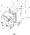
FIG. 1 is a perspective view of a transport vehicle which may utilize one or more aspects of the disclosed embodiments; -
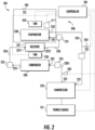
FIG. 2 is a schematic diagram of a refrigeration system of the transport vehicle ofFIG. 1 ; -
FIG. 3 is a side view of a gas detector which may utilize one or more aspects of the disclosed embodiments; -
FIG. 4 is gas detector system according to one disclosed embodiment; -
FIG. 5 is gas detector system according to another disclosed embodiment; -
FIG. 6 is heated gas detector system according to a further disclosed embodiment; and -
FIG. 7 is a flowchart illustrating operation of a heated gas detector system according to an embodiment. - These and other advantages and features will become more apparent from the following description taken in conjunction with the drawings, which is provided by way of example only. Every embodiment obligatorily discloses all the technical features of at least one of the independent claims.
- With reference to
FIG. 1 , atransport system 101 is illustrated and includes a tractor orvehicle 102, a conditionedspace 103 that is pulled by thevehicle 102 and arefrigeration system 104 that conditions the air within the conditionedspace 103. - While the
transport system 101 is described herein as being a conditionedspace 103 pulled byvehicle 102, it is to be understood that embodiments exist in which the conditionedspace 103 is shipped by rail, sea or air or may be provided within any suitable container where thevehicle 102 is a truck, train, boat, airplane, helicopter, etc. - The
vehicle 102 may include an operator's compartment orcab 105 and avehicle motor 106. Thevehicle 102 may be driven by a driver located within the cab, driven by a driver remotely, driven autonomously, driven semi-autonomously or any combination thereof. Thevehicle motor 106 may be an electric or combustion engine powered by a combustible fuel. Thevehicle motor 106 may also be part of the power train or drive system of a trailer system, thus thevehicle motor 106 is configured to propel the wheels of thevehicle 102 and/or the wheels of the conditionedspace 103. Thevehicle motor 106 may be mechanically connected to the wheels of thevehicle 102 and/or the wheels of the conditionedspace 103. - The conditioned
space 103 may be coupled to thevehicle 102 and is thus pulled or propelled to desired destinations. The conditionedspace 103 may include atop wall 110, abottom wall 111 opposed to and spaced from thetop wall 110, twoside walls 112 spaced from and opposed to one-another and opposing front andrear walls front wall 113 being closest to thevehicle 102. The conditionedspace 103 may further include doors (not shown) at therear wall 114 or any other wall. The top, bottom, side and front andback walls interior volume 115. Therefrigeration system 104 is configured to condition the refrigeratedinterior volume 115. - With reference to
FIG. 2 , the conditionedspace 103 may be provided as an interior of a refrigerated trailer, a refrigerated truck, a refrigerated space or a refrigerated container with therefrigeration system 104 adapted to operate using a refrigerant such as a low GWP refrigerant such as A1, A2, A2L, A3, etc. In some cases, the refrigerant may leak into the refrigeratedinterior volume 115 and may present a hazard should the concentration of the leaked refrigerant within refrigeratedinterior volume 115 exceed a threshold level. The threshold level needs to be be a lower flammability limit of the refrigerant. - An evaporator 230, a portion of a
refrigerant line 253 proximate anevaporator outlet 232 and a portion of arefrigerant line 250 proximate anevaporator inlet 231 may be located within the refrigeratedinterior volume 115 of the conditionedspace 103 and thus may be a potential source of a refrigerant leak. - The
refrigeration system 104 may be a transport refrigeration system such as a transportation refrigeration unit (TRU). Therefrigeration system 104 includes acompressor 210, acondenser 220, an evaporator 230 and agas detector system 240 that includes a gas detector (301), which is communicative with acontroller 241. Thegas detector system 240 is arranged to detect and mitigate the presence of refrigerant within the refrigeratedinterior volume 115. - The
compressor 210 is powered by or driven by apower source 211. Thecompressor 210 receives refrigerant through acompressor inlet 212 from the evaporator 230 and discharges refrigerant through acompressor outlet 213 to thecondenser 220 through areceiver 221. Thecondenser 220 receives a fluid flow of refrigerant from thecompressor 210 through acondenser inlet 222 and discharges a fluid flow of refrigerant through acondenser outlet 223 to thereceiver 221. Thecondenser inlet 222 is fluidly connected to thecompressor outlet 213 through arefrigerant line 2201. A fan, such as acondenser fan 224, may be associated with and disposed proximate to thecondenser 220. - The evaporator 230 is arranged to receive a fluid flow of refrigerant from the
condenser 220 through anevaporator inlet 231 and is arranged to discharge a fluid flow of refrigerant to thecompressor 210 through anevaporator outlet 232. Theevaporator inlet 231 is fluidly connected to thecondenser outlet 223 through thereceiver 221 via arefrigerant line 250 through afirst valve 251 and/or asecond valve 252 that is disposed on an opposite side of thereceiver 221 than thefirst valve 251. Theevaporator outlet 232 is fluidly connected to thecompressor inlet 212 through arefrigerant line 253. A fan such as anevaporator fan 233 may be associated with and disposed proximate to the evaporator 230. - The
first valve 251 may be an expansion valve such as an electronic expansion valve, a movable valve or a thermal expansion valve. Thefirst valve 251 is movable between an open position and a closed position to selectively inhibit and facilitate a fluid flow of refrigerant between the evaporator 230 and at least one of thecondenser 220 and thereceiver 221. The open position facilitates a fluid flow of refrigerant between theevaporator inlet 231 and thecondenser outlet 223 through thereceiver 221. The closed position inhibits a fluid flow of refrigerant between theevaporator inlet 231 and thecondenser outlet 223 through thereceiver 221 as well as inhibits a fluid flow of refrigerant between thereceiver 221 and theevaporator inlet 231. - The
receiver 221 is fluidly connected to thecondenser 220 and the evaporator 230 and is arranged to receive and store refrigerant based on a position of at least one of thefirst valve 251 and/or thesecond valve 252. Thereceiver 221 is arranged to receive refrigerant from thecondenser outlet 223 through afirst receiver inlet 2211 via therefrigerant line 250. In at least one embodiment, thesecond valve 252 is arranged to selectively facilitate a fluid flow between thecondenser outlet 223 and thefirst receiver inlet 2211. Thesecond valve 252 may be a movable valve, a solenoid valve, a liquid service valve, a thermal expansion valve or an electronic expansion valve and is movable between open and closed positions to facilitate or impede a fluid flow of refrigerant between thecondenser outlet 223 and thefirst receiver inlet 2211. Thereceiver 221 is arranged to discharge or provide a fluid flow of refrigerant through areceiver outlet 2212 to theevaporator inlet 231 via thefirst valve 251 through therefrigerant line 250. - A
third valve 254 may be arranged to selectively facilitate a fluid flow between thecompressor outlet 213 and thecondenser inlet 222. Thethird valve 254 may be a movable valve, check valve, a liquid service valve, a thermal expansion valve, or an electronic expansion valve and is movable between open and closed positions to facilitate or impede a fluid flow of refrigerant between thecompressor outlet 213 and thecondenser inlet 222. - A
fourth valve 255 may be arranged to selectively facilitate a fluid flow between theevaporator outlet 232 and thecompressor inlet 212. Thefourth valve 255 may be a movable valve, check valve, a liquid service valve, a thermal expansion valve, or an electronic expansion valve and is movable between open and closed positions to facilitate or impede a fluid flow of refrigerant between theevaporator outlet 232 and thecompressor inlet 212. - The
gas detector system 240 includes the gas detector (301), which is communicative with thecontroller 241. The gas detector (301) is configured to detect a selected concentration of refrigerant and thus to detect a refrigerant leak within the refrigeratedinterior volume 115 of the conditionedspace 103. - The
controller 241 is provided with input communication channels that are arranged to receive information, data, or signals from, for example, thecompressor 210, thepower source 211, thecondenser fan 224, thefirst valve 251, theevaporator fan 233, thesecond valve 252, apressure sensor 243, a compressordischarge pressure sensor 244 and the gas detector (301). Thecontroller 241 is provided with output communication channels that are arranged to provide commands, signals, or data to, for example, thecompressor 210, thepower source 211, thecondenser fan 224, thefirst valve 251, theevaporator fan 233 and thesecond valve 252. - The
controller 241 can be provided with at least one processor that is programmed to execute various operations including, but not limited to, a leak detection and/or leak mitigation strategy based on information, data, or signals provided via the input communication channels and output commands via the output communication channels. - The gas detector (301) is arranged to provide a signal indicative of a concentration, amount or the presence of refrigerant within the refrigerated
interior volume 115 of the conditionedspace 103 to thecontroller 241. The gas detector (301) may be disposed proximate to the evaporator 230 and/or may be disposed proximate therefrigerant line 250 or any other refrigerant line or component that could leak refrigerant into the conditionedspace 103. The gas detector (301) may also be located near a likely location where refrigerant may collect, such as near thebottom wall 111. - While the
refrigeration system 104 has been described in accordance with embodiments herein, it is to be understood that other embodiments of therefrigeration system 104 and that other conditioning systems exist and that the following description is relevant to each of these various embodiments and systems. - With reference to
FIG. 3 , a gas detector (detector) 301 is provided as shown also inFIG. 2 . Thegas detector 301 includes agas sensing element 310,gas detector electronics 320 that are configured to control operations of thegas detector element 310 and to communicate with thecontroller 241, a printed circuit board (PCB) 330 on which thegas detector element 310 and thegas detector electronics 320 are disposed and anenclosure 410. Theenclosure 410 is configured to expose thegas sensing element 310 to an exterior (i.e., to the refrigeratedinterior volume 115, any gases or fluids therein and, in particular, to any leaked refrigerant therein). Theenclosure 410 contains thePCB 330 to form an electronics housing which functions as agas detection chamber 350. Thegas detector electronics 320 are disposed in thegas detection chamber 350 whereby thegas detector electronics 320 are isolated from the exterior. - As shown in
FIG. 3 , thePCB 330 may include a solid,unitary body 331, which is configured to impede fluid flow from the exterior, through theenclosure 410 and into thegas detection chamber 350. Theenclosure 410 includes abody 341 and acover 342. From this configuration thePCB 330 is substantially surrounded by thebody 341 and thecover 342. One side of thePCB 330 facing thecover 342 and another second side of thePCB 330 facing thebody 341. Thecover 342 is formed to define anaperture 343 through which thegas detector element 310 is exposed to the exterior and which may or may not have ribs extending across open space. Thebody 341 is formed to define, in cooperation with thePCB 330, thegas detection chamber 350 in which thegas detector electronics 320 are disposable. - The
body 341 may include a back-plane 3410 that faces thePCB 330 andsidewalls 3411 that are connected to thePCB 330 and positions the back-plane 3410 at a distance D from thePCB 330. Thegas detection chamber 350 may be thus delimited by the back-plane 3410, thesidewalls 3411 and thePCB 330. The distance D may be sufficient to at least tightly accommodate thegas detector electronics 320. Thecover 342 may include acover portion 3421 and aspacer portion 3422, which may be separate components or integrally provided together in a single component, and which is interposed between thePCB 330 and thecover portion 3421. Thespacer portion 3422 may include aseal 3424. - The
gas detector 301 is an infrared (IR) detector in that it detects gas by monitoring for infrared wavelength absorption or attenuation used in IR sensors embodied in the sensing element. The ability of thegas detector 301 to operate is effected by the level of humidity in the air, and may change the values sensed by thegas detector 301 if temperatures around or inside thegas detector 301 are different than the air entering thegas detector 301. This may create false readings due to calibration errors, causing false triggers of a gas detection or allowing moisture to condense or even freeze in cold environments within thegas detection chamber 350. This may damage thegas detector electronics 320. - In view of the above identified concerns, a sensor system (system) 400 is disclosed in
FIGS. 4-6 . The system 400 includes a gas detector (detector) 301. For example, thegas detector 301 includes anenclosure 410 with a plurality ofsidewalls 430, acover 440 and a back-plane 450. Theenclosure 410 defines a gas detection chamber (chamber) 460, and the cover includes achamber opening 470. Gas detector electronics which may comprise anIR sensor 480 are within thechamber 460. Thedetector 301 is configured as a non-dispersive infrared (NDIR) detector. Thegas detector 301 operationally communicates with thecontroller 241. - According to the disclosed embodiments the gas detector system 400 includes a
heater 500 that is operationally connected to thecontroller 241. Theheater 500 may include first set ofheating elements 510. In the embodiment illustrated inFIG. 4 , theheater 500 includes a plurality of sets ofheating elements 520 including the first set ofheating elements 510 and a second set ofheating elements 530. The plurality of sets ofheating elements 520 are exterior to theenclosure 410. The first set ofheating elements 510 is adjacent one or more of the plurality ofsidewalls 430. More specifically, the first set ofheating elements 510 is adjacent afirst sidewall 535 of the plurality ofsidewalls 430. The second set ofheating elements 530 is adjacent asecond sidewall 540 of the plurality ofsidewalls 430. - In the embodiment illustrated in
FIG. 5 , theheater 500 includes the first set ofheating elements 510. The first set ofheating elements 510 is exterior to theenclosure 410. The first set ofheating elements 510 is adjacent the back-plane 450. In the embodiment illustrated inFIG. 6 , theheater 500 includes the first set ofheating elements 510. The first set ofheating elements 510 is disposed in thechamber 460. The first set ofheating elements 510 is against the back-plane 450. The plurality of sets ofheating elements 520 are each illustrated as having a plurality of heating elements and more specifically three heating elements. However the number of heating elements is not intended on being limiting. - In each of the embodiments illustrated in
FIGS. 4-6 , anenclosure temperature sensor 600 is disposed within or proximate to theenclosure 410. Thecontroller 241 utilizes temperature readings from theenclosure temperature sensor 600 to control theheater 500. Thecontroller 241 utilizes such temperature readings either alone or in comparison with temperature readings from anambient temperature sensor 610 that reads an ambient temperature in or around the TRU. Ahumidity sensor 620 may be disposed within or proximate to theenclosure 410. Thecontroller 241 may utilize humidity level readings from thehumidity sensor 620 to control theheater 500. A method of utilizing the temperature readings and/or humidity readings to control theheater 500 are disclosed below and illustrated inFIG. 7 . - With reference now to
FIG. 4-7 a flowchart (FIG. 7 ) shows a method of operating the system 400. As illustrated inblock 900 the method includes heating anenclosure 410 of thedetector 301 during a refrigeration cycle to reduce moisture within theenclosure 410 and/or prevent moisture from accumulating from within theenclosure 410. As indicated theenclosure 410 includes acover 440, a back-plane 450 and a plurality ofsidewalls 430 to define achamber 460 therein. Thecover 440 includes achamber opening 470. An infrared sensor (IR sensor) 480 is disposed within thechamber 460. Aheater 500 for heating theenclosure 410 is adjacent to or within theenclosure 410. Theheater 500 is operationally connected to the controller 241 (FIG. 4 ). - As illustrated in block 910, the gas detector system 400 operates in accordance with one of a plurality of modes, depending on a configuration of the system 400. As illustrated in block 920, in a first operational mode (
MODE 1 at block 910) heating the enclosure when a temperature inside or proximate to the enclosure is less than ambient temperature during the refrigeration cycle. To function in this mode of operation anenclosure temperature sensor 600 is operationally connected to theheater 500. Theenclosure temperature sensor 600 is disposed inside or proximate to theenclosure 410. InFIGS. 4-6 , theenclosure temperature sensor 600 is schematically illustrated inside theenclosure 410. Anambient temperature sensor 610 reads ambient temperature. Theambient temperature sensor 610 is located outside of a refrigerated interior volume (seeFIG. 2 ). As illustrated in block 930, in this mode of operation the method may include delaying or suspending the refrigeration cycle while heating the enclosure 410 d until the temperature inside or proximate to theenclosure 410 is greater than or equal to ambient temperature. - As illustrated in
block 940, in a second operational mode (MODE 2 at block 910), the method includes heating theenclosure 410 when a humidity level inside or proximate to theenclosure 410 is greater than a humidity threshold during the refrigeration cycle. For this mode of operation ahumidity sensor 620 is operationally connected to theheater 500. Thehumidity sensor 620 is disposed inside or proximate to theenclosure 410. InFIGS. 4-6 , thehumidity sensor 620 is schematically illustrated inside theenclosure 410. In this mode of operation, as shown inblock 950, the method includes delaying or suspending the refrigeration cycle while heating theenclosure 410 and until the humidity level inside or proximate to theenclosure 410 is less than the humidity threshold. - As shown in block 960, in a third mode of operation (
MODE 3 at block 910) the method includes heating theenclosure 410 upon initiating the refrigeration cycle and until a temperature threshold is reached. For this mode of operation, as with the first mode of operation, theenclosure temperature sensor 600 is operationally connected to theheater 500. Theenclosure temperature sensor 600 being disposed inside or proximate to the enclosure. In this mode of operation, as shown inblock 970, the method includes periodically pulsating heat during the refrigeration cycle after the temperature threshold is reached. As shown in block 980, the method further includes delaying or suspending the initiation of the refrigeration cycle while heater is heating theenclosure 410 and until the temperature inside or proximate to theenclosure 410 has reached the temperature threshold. - In one embodiment a combination of the above identified modes is utilized to reduce moisture within the enclosure and/or prevent moisture from accumulating from within the enclosure. Additionally, thresholds identified herein may vary according to a psychrometric understanding, thereby ensuring that the sensor operates at temperature and humidity levels where calibration is capable of being executed and the reading are more accurate.
- According to the above disclosed embodiments, a gas detector system (system) 400 is provided to melt and vaporize frozen moisture inside the
gas detection chamber 350, and to increase temperatures within thegas detection chamber 350 to promote elimination of moisture inside thegas detection chamber 350. It will also actively prevent moisture from reentering thegas detection chamber 350. The system 400 utilizesenclosure temperature sensor 600, theambient temperature sensor 610 and/or thehumidity sensor 620 disposed around thegas detector electronics 320 to determine when thedetector 301 identifies correctly if detectable gas is present in the atmosphere. The disclosed embodiments may enhance the utilization of a gas detector using IR technology for accuracy and robustness. The disclosed embodiments also provide a control logic that may enable saving power consumption if limited power source is applied. - The terminology used herein is for the purpose of describing particular embodiments only and is not intended to be limiting of the present invention. As used herein, the singular forms "a", "an" and "the" are intended to include the plural forms as well, unless the context clearly indicates otherwise. It will be further understood that the terms "comprises" and/or "comprising," when used in this specification, specify the presence of stated features, integers, steps, operations, elements, and/or components, but do not preclude the presence or addition of one or more other features, integers, steps, operations, element components, and/or groups thereof.
- Accordingly, the present invention is not to be seen as limited by the foregoing description, but is only limited by the scope of the appended claims.
Claims (15)
- A gas detector system for a refrigerated interior volume (115) of a transportation refrigeration unit, TRU, the gas detector system comprising:a heated non-dispersive infrared, NDIR, gas detector (301) for flammable low global warming potential, GWP, refrigerants that defines an enclosure (410), the enclosure (410) defines a chamber (350) therein, a cover (342) including a chamber opening (470), and an infrared (IR) sensing element (480) within the chamber;a heater (500) adjacent to or within the enclosure (410), the heater (500) configured to reduce moisture within the chamber (350) and/or prevent moisture from accumulating within the chamber (350) during a refrigeration cycle;a controller (241) configured to control the heater (500),a gas detector element (310);gas detector electronics (320) configured to control operations of the gas detector element (310) and to communicate with the controller (241) anda printed circuit board (330) on which the gas detector element (310) and the gas detector electronics (320) are disposed, whereinthe gas detector system is configured to detect a selected concentration of refrigerant and thus to detect a refrigerant leak within the refrigerated interior volume of the TRU, wherein the gas detector system comprisesan enclosure temperature sensor (600) disposed inside or proximate to the enclosure (410),an ambient temperature sensor (610) disposed outside of the refrigerated interior volume (115),wherein the controller (241) is configured to compare temperature readings from the enclosure temperature sensor (600) and the ambient temperature sensor (610) and utilize the comparison of the readings to control the heater (500),wherein during the refrigeration cycle:when a temperature inside or proximate to the enclosure (410) is less than ambient temperature, the heater (500) is activated; andwhen the temperature inside or proximate to the enclosure (410) is greater than ambient temperature, the heater (500) is deactivated.
- A gas detector system for a refrigerated interior volume (115) of a transportation refrigeration unit, TRU, the system comprising:a heated non-dispersive infrared, NDIR, gas detector (301) for flammable low global warming potential (GWP) refrigerants that defines an enclosure (410), the enclosure (410) defines a chamber (350) therein, a cover (342) including a chamber opening (470), and an infrared, IR, sensing element (480) within the chamber (350),a heater (500) adjacent to or within the enclosure (410), the heater (500) configured to reduce moisture within the chamber (350) and/or prevent moisture from accumulating within the chamber (350) during a refrigeration cycle,a controller (241) configured to control the heater (500),a gas detector element (310);gas detector electronics (320) configured to control operations of the gas detector element (310) and to communicate with the controller (241), anda printed circuit board (330) on which the gas detector element (310) and the gas detector electronics (320) are disposed, whereinthe gas detector system is configured to detect a selected concentration of refrigerant and thus to detect a refrigerant leak within the refrigerated interior volume (115) of the TRU, wherein the gas detector system comprisesa humidity sensor (620) operationally connected to the heater (500), disposed inside or proximate to the enclosure (410), wherein during the refrigeration cycle:when a relative humidity level inside or proximate to the enclosure (410) is greater than a humidity threshold, the heater (500) is activated; andwhen the relative humidity level inside or proximate to the enclosure (410) is less than the humidity threshold, the heater (500) is deactivated.
- A gas detector system for a refrigerated interior volume (115) of a transportation refrigeration unit, TRU, the system comprising:a heated non-dispersive infrared, NDIR, gas detector (301) for flammable low global warming potential, GWP, refrigerants that defines an enclosure (410), the enclosure (410) defines a chamber (350) therein, a cover (342) including a chamber opening (470), and an infrared (IR) sensing element (480) within the chamber (350), anda heater (500) adjacent to or within the enclosure (410), the heater (500) configured to reduce moisture within the chamber (350) and/or prevent moisture from accumulating within the chamber (350) during a refrigeration cycle, wherein the heater (500) comprises a plurality of heating elements (520) mutually spaced alongside one or more of the plurality of sidewalls (430) of the enclosure (410) or within the chamber (350),a controller (241) operationally connected to the heater (500),a gas detector element (310);gas detector electronics (320) configured to control operations of the gas detector element (310) and to communicate with the controller (241), anda printed circuit board (330) on which the gas detector element (310) and the gas detector electronics (320) are disposed, whereinthe gas detector system is configured to detect a selected concentration of refrigerant and thus to detect a refrigerant leak within the refrigerated interior volume (115) of the TRU, wherein the gas detector system comprisesan enclosure temperature sensor (600) operationally connected to the heater (500), the enclosure temperature sensor (600) disposed inside or proximate to the enclosure (410), wherein:
the heater (500) is activated upon initiating the refrigeration cycle, and when a temperature threshold is reached at the enclosure (410), the heater (500) is deactivated. - The gas detector system of claim 1, comprising a humidity sensor (620) operationally connected to the heater (500), disposed inside or proximate to the enclosure (410), wherein during the refrigeration cycle:when a relative humidity level inside or proximate to the enclosure (410) is greater than a humidity threshold, the heater (500) is activated; andwhen the relative humidity level inside or proximate to the enclosure (410) is less than the humidity threshold, the heater (500) is deactivated.
- The gas detector system of claim 4, wherein the temperature threshold and humidity threshold vary and correlate with one another.
- A transportation refrigeration unit, TRU, comprising a compressor (210), a condenser (220), an evaporator (230), and a refrigerated interior volume (115), the refrigerated interior volume (115) including the gas detector system of claim 1, wherein the controller (241) is operationally connected to the compressor (210), the condenser (220) and the evaporator (230).
- The transportation refrigeration unit (TRU) of claim 6, wherein the controller (241) is configured to delay or suspend the refrigeration cycle while the heater (500) is heating the enclosure (410) and until the temperature inside or proximate to the enclosure (410) is greater than or equal to ambient temperature.
- A transportation refrigeration unit (TRU) comprising a compressor (210), a condenser (220), an evaporator (230) and a refrigerated interior volume (115), the refrigerated interior volume (115) including the gas detector system of claim 2, wherein the controller (241) is operationally connected to the compressor (210), the condenser (220) and the evaporator (230), optionally wherein the controller (241) is configured to delay or suspend the refrigeration cycle while the heater (500) is heating the enclosure (410) and until the humidity level inside or proximate to the enclosure (410) is less than the humidity threshold.
- A transportation refrigeration unit (TRU) comprising a compressor (210), a condenser (220), an evaporator (230), and a refrigerated interior volume (115), the refrigerated interior volume (115) including the gas detector system of claim 3, wherein the controller (241) is operationally connected to the compressor (210), the condenser (220) and the evaporator (230), optionally wherein when initiating the refrigeration cycle the controller (241) is configured to delay or suspend the refrigeration cycle while the heater (500) is heating the enclosure (410) and until the temperature inside or proximate to the enclosure (410) has reached the temperature threshold.
- A method of operating a gas detector system according to claim 1 for a refrigerated interior volume (115) of a transportation refrigeration unit, TRU, the method comprising: heating an enclosure (410) of a gas detector (301) during a refrigeration cycle to reduce moisture within the enclosure (410) and/or prevent moisture from accumulating from within the enclosure (410), wherein the enclosure (410) defines a chamber (350) therein, a cover (342) including a chamber opening (470), and an infrared, IR, sensor (480) is disposed within the chamber (350), wherein a heater (500) configured for heating the enclosure (410) is adjacent to or within the enclosure (410), and wherein the gas detector (301) is a heated non-dispersive infrared, NDIR, gas detector (301) for flammable low global warming potential, GWP, refrigerants, wherein the gas detector system comprises: a controller (241) configured to control the heater (500), a gas detector element (310); gas detector electronics (320) configured to control operations of the gas detector element (310) and to communicate with the controller (241), a printed circuit board (330) on which the gas detector element (310) and the gas detector electronics (320) are disposed, and an ambient temperature sensor (610) disposed outside of the refrigerated interior volume (115), wherein the gas detector system is configured to detect a selected concentration of refrigerant and thus to detect a refrigerant leak within the refrigerated interior volume (115) of the TRU, the method further comprises the following steps:comparing temperature readings from an enclosure temperature sensor (600) disposed inside or proximate to the enclosure (410) and the ambient temperature sensor (610) using the controller (241) and utilizing the comparison of the readings to control the heater (500) using the controller (241),heating the enclosure (410) when a temperature inside or proximate to the enclosure (410) is less than ambient temperature during the refrigeration cycle, wherein the enclosure temperature sensor (600) is operationally connected to the heater (500), anddeactivating the heater (500) when the temperature inside or proximate to the enclosure (410) is greater than ambient temperature.
- A method of operating a gas detector system according to claim 2 for a refrigerated interior volume (115) of a transportation refrigeration unit, TRU, the method comprising: heating an enclosure (410) of a gas detector (301) during a refrigeration cycle to reduce moisture within the enclosure (410) and/or prevent moisture from accumulating from within the enclosure (410), wherein the enclosure (410) defines a chamber (350) therein, a cover (342) including a chamber opening (470), and an infrared (IR) sensor (480) is disposed within the chamber (350), and wherein a heater (500) configured for heating the enclosure (410) is adjacent to or within the enclosure (410), wherein the gas detector (301) is a heated non-dispersive infrared (NDIR) gas detector (301) for flammable low global warming potential (GWP) refrigerants, wherein the gas detector system comprises: a controller (241) configured to control the heater (500), a gas detector element (310); gas detector electronics (320) configured to control operations of the gas detector element (310) and to communicate with the controller (241), and a printed circuit board (330) on which the gas detector element (310) and the gas detector electronics (320) are disposed, and wherein the gas detector system is configured to detect a selected concentration of refrigerant and thus to detect a refrigerant leak within the refrigerated interior volume (115) of the transportation refrigeration unit (TRU), the method further comprises the following steps:heating the enclosure (410) when a humidity level inside or proximate to the enclosure (410) is greater than a humidity threshold during the refrigeration cycle, wherein a humidity sensor (620) is operationally connected to the heater (500), and the humidity sensor (620) is disposed inside or proximate to the enclosure (410), anddeactivating the heater (500) when the relative humidity level inside or proximate to the enclosure (410) is less than the humidity threshold.
- A method of operating a gas detector system according to claim 3 for a refrigerated interior volume (115) of a transportation refrigeration unit, TRU, the method comprising: heating an enclosure (410) of a gas detector (301) during a refrigeration cycle to reduce moisture within the enclosure (410) and/or prevent moisture from accumulating from within the enclosure (410), wherein the enclosure (410) defines a chamber (350) therein, a cover (342) including a chamber opening (370), and an infrared, IR sensor (480) is disposed within the chamber (350), and wherein a heater (500) configured for heating the enclosure (410) is adjacent to or within the enclosure (410), wherein the gas detector (301) is heated non-dispersive infrared, NDIR gas detector (301) for flammable low global warming potential, GWP, refrigerants, wherein the gas detector system comprises: a controller (241) configured to control the heater (500), a gas detector element (310); gas detector electronics (320) configured to control operations of the gas detector element (310) and to communicate with the controller (241), and a printed circuit board (330) on which the gas detector element (310) and the gas detector electronics (320) are disposed, and wherein the gas detector system is configured to detect a selected concentration of refrigerant and thus to detect a refrigerant leak within the refrigerated interior volume (115) of the TRU, the method further comprises the following steps:heating the enclosure (410) upon initiating the refrigeration cycle and until a temperature threshold is reached, wherein an enclosure temperature sensor (600) is operationally connected to the heater (500), the enclosure temperature sensor (600) being disposed inside or proximate to the enclosure (410), anddeactivating the heater (500) when a temperature threshold is reached at the enclosure (410).
- The method of claim 10, further comprising delaying or suspending the refrigeration cycle while heating the enclosure (410) and until the temperature inside or proximate to the enclosure (410) is greater than or equal to ambient temperature
- The method of claim 11, further comprising delaying or suspending the refrigeration cycle while heating the enclosure (410) and until the relative humidity level inside or proximate to the enclosure (410) is less than the relative humidity threshold.
- The method of claim 12, comprising periodically pulsating heat during the refrigeration cycle after the temperature threshold is reached, optionally
further comprising delaying or suspending the initiating of the refrigeration cycle while heating the enclosure (410) and until the temperature inside or proximate to the enclosure (410) has reached the temperature threshold.
Applications Claiming Priority (2)
| Application Number | Priority Date | Filing Date | Title |
|---|---|---|---|
| US201962902112P | 2019-09-18 | 2019-09-18 | |
| PCT/US2020/050105 WO2021055221A1 (en) | 2019-09-18 | 2020-09-10 | Heated gas detector for a transpotation refrigeration unit |
Publications (2)
| Publication Number | Publication Date |
|---|---|
| EP3833914A1 EP3833914A1 (en) | 2021-06-16 |
| EP3833914B1 true EP3833914B1 (en) | 2023-05-03 |
Family
ID=72644942
Family Applications (1)
| Application Number | Title | Priority Date | Filing Date |
|---|---|---|---|
| EP20780468.3A Active EP3833914B1 (en) | 2019-09-18 | 2020-09-10 | Heated gas detector for a transportation refrigeration unit |
Country Status (4)
| Country | Link |
|---|---|
| US (1) | US11827080B2 (en) |
| EP (1) | EP3833914B1 (en) |
| CN (1) | CN113015641B (en) |
| WO (1) | WO2021055221A1 (en) |
Families Citing this family (9)
| Publication number | Priority date | Publication date | Assignee | Title |
|---|---|---|---|---|
| US11231198B2 (en) | 2019-09-05 | 2022-01-25 | Trane International Inc. | Systems and methods for refrigerant leak detection in a climate control system |
| US12253457B2 (en) * | 2021-09-30 | 2025-03-18 | Carrier Corporation | Environmental enclosure for a transport gas sensor |
| USD1027682S1 (en) | 2021-09-30 | 2024-05-21 | Carrier Corporation | Refrigerant detection sensor housing |
| US12487008B2 (en) | 2022-01-14 | 2025-12-02 | Trane International Inc. | Method of commissioning an HVAC system |
| US12117191B2 (en) | 2022-06-24 | 2024-10-15 | Trane International Inc. | Climate control system with improved leak detector |
| USD1115569S1 (en) | 2022-11-28 | 2026-03-03 | Danfoss A/S | Gas detection sensor |
| USD1119637S1 (en) | 2023-02-09 | 2026-03-24 | Danfoss A/S | Gas detection sensor |
| USD1115570S1 (en) | 2023-08-15 | 2026-03-03 | Danfoss A/S | Gas detection sensor |
| CN119245244A (en) * | 2024-09-11 | 2025-01-03 | 广州万居隆科技有限公司 | An air energy heat pump explosion-proof system and method |
Family Cites Families (28)
| Publication number | Priority date | Publication date | Assignee | Title |
|---|---|---|---|---|
| US5468961A (en) | 1991-10-08 | 1995-11-21 | Fisher & Paykel Limited | Infrared gas analyser and humidity sensor |
| US5792427A (en) | 1996-02-09 | 1998-08-11 | Forma Scientific, Inc. | Controlled atmosphere incubator |
| US5886348A (en) | 1997-02-14 | 1999-03-23 | American Intell-Sensors Corporation | Non-dispersive infrared gas analyzer with interfering gas correction |
| US7301148B2 (en) | 2003-04-23 | 2007-11-27 | Battelle Memorial Institute | Methods and systems for remote detection of gases |
| SE526939C2 (en) | 2003-10-28 | 2005-11-22 | Flir Systems Ab | Method, arrangement and use of an IR camera to determine the risk of condensation by recording IR image, relative humidity and air temperature |
| JP2005292009A (en) | 2004-04-01 | 2005-10-20 | Denso Corp | Infrared gas detector and detection method |
| JP2006038721A (en) | 2004-07-29 | 2006-02-09 | Denso Corp | Gas concentration detector |
| US7332716B2 (en) | 2005-06-06 | 2008-02-19 | Flir Systems Ab | IR camera |
| US9121634B2 (en) | 2010-04-13 | 2015-09-01 | Carrier Corporation | Controlled atmosphere systems and methods |
| EP2678841A1 (en) | 2011-02-22 | 2014-01-01 | Flir System, Inc. | Infrared sensor systems and methods |
| DE202011102765U1 (en) | 2011-07-02 | 2012-08-02 | Dräger Safety AG & Co. KGaA | Device with a measuring arrangement for the infrared-optical measurement of gases and gas mixtures with compensation of environmental influences |
| US9551651B2 (en) | 2013-06-19 | 2017-01-24 | Digi-Star, Llc | Handheld moisture sensor device |
| WO2015029094A1 (en) * | 2013-08-25 | 2015-03-05 | Masuda Keiji | Leak detecting structure for flammable refrigerant |
| WO2015032905A1 (en) * | 2013-09-05 | 2015-03-12 | Holger König | Method for preventing leakage from a container and a container having leakage safeguard |
| EP3109576B1 (en) | 2014-03-31 | 2020-12-09 | Daikin Industries, Ltd. | Refrigeration device for container |
| DE102014010712A1 (en) | 2014-07-19 | 2016-01-21 | Paragon Ag | "Gas sensor arrangement for measuring a target gas concentration" |
| DE102014010713A1 (en) | 2014-07-19 | 2016-01-21 | Paragon Ag | "Gas sensor arrangement for measuring a target gas concentration" |
| JP6402779B2 (en) * | 2014-12-25 | 2018-10-10 | 三菱電機株式会社 | Refrigerant leak detection device and refrigeration cycle device provided with the same |
| JP2017053514A (en) * | 2015-09-08 | 2017-03-16 | ジョンソンコントロールズ ヒタチ エア コンディショニング テクノロジー(ホンコン)リミテッド | Air conditioner |
| WO2017083336A1 (en) | 2015-11-09 | 2017-05-18 | Carrier Corporation | Refrigerated transport system with refrigerant dilution |
| WO2017109847A1 (en) * | 2015-12-22 | 2017-06-29 | 三菱電機株式会社 | Air conditioner |
| KR20170088218A (en) | 2016-01-22 | 2017-08-01 | 한림대학교 산학협력단 | Device and Method for Gas Concentration Measurement using Infrared Sensors |
| JP2017207245A (en) * | 2016-05-19 | 2017-11-24 | 日立ジョンソンコントロールズ空調株式会社 | Air conditioner |
| GB2562275A (en) | 2017-05-10 | 2018-11-14 | Univ Warwick | Monitoring of an agricultural product and/or the environment in the vicinity of the agricultural product |
| JP7332273B2 (en) * | 2018-02-09 | 2023-08-23 | 三菱重工サーマルシステムズ株式会社 | air conditioner |
| CN108195788B (en) | 2018-03-13 | 2023-12-08 | 南京信息工程大学 | A sulfur dioxide gas sensor and its temperature and humidity correction method |
| CN208206922U (en) | 2018-05-30 | 2018-12-07 | 南京信息工程大学 | A kind of infrared CO2Gas sensor and its calibration system |
| CN110006838A (en) | 2019-05-05 | 2019-07-12 | 南京信息工程大学 | An adjustable infrared gas sensor system and temperature and humidity compensation method |
-
2020
- 2020-09-10 US US16/973,341 patent/US11827080B2/en active Active
- 2020-09-10 WO PCT/US2020/050105 patent/WO2021055221A1/en not_active Ceased
- 2020-09-10 CN CN202080003576.7A patent/CN113015641B/en active Active
- 2020-09-10 EP EP20780468.3A patent/EP3833914B1/en active Active
Also Published As
| Publication number | Publication date |
|---|---|
| EP3833914A1 (en) | 2021-06-16 |
| CN113015641B (en) | 2026-04-24 |
| WO2021055221A1 (en) | 2021-03-25 |
| US11827080B2 (en) | 2023-11-28 |
| US20220297510A1 (en) | 2022-09-22 |
| CN113015641A (en) | 2021-06-22 |
Similar Documents
| Publication | Publication Date | Title |
|---|---|---|
| EP3833914B1 (en) | Heated gas detector for a transportation refrigeration unit | |
| US11662109B2 (en) | Enclosure for gas detector | |
| EP3847401B1 (en) | Refrigerant leak detection system | |
| EP3850282B1 (en) | Refrigerant leak detection system | |
| US12253457B2 (en) | Environmental enclosure for a transport gas sensor | |
| US6910341B2 (en) | Temperature control apparatus and method of operating the same | |
| EP3374703B1 (en) | Series loop intermodal container | |
| EP2991845B1 (en) | Refrigerated container with dual air curtain | |
| US7137262B2 (en) | Supplemental heat control apparatus and method for freezer/refrigeration equipment | |
| EP3811008B1 (en) | Refrigerated container provided with ventilation system | |
| CN111829218A (en) | Refrigerant System Operation Sequence for Leak Prevention | |
| EP3394528B1 (en) | Safety system for a container having a refrigeration system and method of providing safety | |
| EP3094931B1 (en) | Fuel regeneration using waste heat of refrigeration unit | |
| EP3586073B1 (en) | Methane-powered refrigeration unit | |
| EP3990845B1 (en) | Transportation refrigeration unit with adaptive defrost |
Legal Events
| Date | Code | Title | Description |
|---|---|---|---|
| STAA | Information on the status of an ep patent application or granted ep patent |
Free format text: STATUS: UNKNOWN |
|
| STAA | Information on the status of an ep patent application or granted ep patent |
Free format text: STATUS: THE INTERNATIONAL PUBLICATION HAS BEEN MADE |
|
| PUAI | Public reference made under article 153(3) epc to a published international application that has entered the european phase |
Free format text: ORIGINAL CODE: 0009012 |
|
| STAA | Information on the status of an ep patent application or granted ep patent |
Free format text: STATUS: REQUEST FOR EXAMINATION WAS MADE |
|
| 17P | Request for examination filed |
Effective date: 20210116 |
|
| AK | Designated contracting states |
Kind code of ref document: A1 Designated state(s): AL AT BE BG CH CY CZ DE DK EE ES FI FR GB GR HR HU IE IS IT LI LT LU LV MC MK MT NL NO PL PT RO RS SE SI SK SM TR |
|
| STAA | Information on the status of an ep patent application or granted ep patent |
Free format text: STATUS: EXAMINATION IS IN PROGRESS |
|
| 17Q | First examination report despatched |
Effective date: 20210804 |
|
| REG | Reference to a national code |
Ref country code: DE Ref legal event code: R079 Ref document number: 602020010499 Country of ref document: DE Free format text: PREVIOUS MAIN CLASS: F25D0011000000 Ipc: B60H0001320000 |
|
| RIC1 | Information provided on ipc code assigned before grant |
Ipc: F25D 29/00 20060101ALI20221028BHEP Ipc: F25D 21/04 20060101ALI20221028BHEP Ipc: F25D 21/00 20060101ALI20221028BHEP Ipc: F25D 19/00 20060101ALI20221028BHEP Ipc: F25D 11/00 20060101ALI20221028BHEP Ipc: B60H 1/32 20060101AFI20221028BHEP |
|
| GRAP | Despatch of communication of intention to grant a patent |
Free format text: ORIGINAL CODE: EPIDOSNIGR1 |
|
| STAA | Information on the status of an ep patent application or granted ep patent |
Free format text: STATUS: GRANT OF PATENT IS INTENDED |
|
| DAV | Request for validation of the european patent (deleted) | ||
| DAX | Request for extension of the european patent (deleted) | ||
| INTG | Intention to grant announced |
Effective date: 20221212 |
|
| GRAS | Grant fee paid |
Free format text: ORIGINAL CODE: EPIDOSNIGR3 |
|
| GRAA | (expected) grant |
Free format text: ORIGINAL CODE: 0009210 |
|
| STAA | Information on the status of an ep patent application or granted ep patent |
Free format text: STATUS: THE PATENT HAS BEEN GRANTED |
|
| AK | Designated contracting states |
Kind code of ref document: B1 Designated state(s): AL AT BE BG CH CY CZ DE DK EE ES FI FR GB GR HR HU IE IS IT LI LT LU LV MC MK MT NL NO PL PT RO RS SE SI SK SM TR |
|
| REG | Reference to a national code |
Ref country code: GB Ref legal event code: FG4D |
|
| REG | Reference to a national code |
Ref country code: AT Ref legal event code: REF Ref document number: 1564295 Country of ref document: AT Kind code of ref document: T Effective date: 20230515 Ref country code: CH Ref legal event code: EP |
|
| REG | Reference to a national code |
Ref country code: DE Ref legal event code: R096 Ref document number: 602020010499 Country of ref document: DE |
|
| REG | Reference to a national code |
Ref country code: IE Ref legal event code: FG4D |
|
| REG | Reference to a national code |
Ref country code: LT Ref legal event code: MG9D |
|
| REG | Reference to a national code |
Ref country code: NL Ref legal event code: MP Effective date: 20230503 |
|
| REG | Reference to a national code |
Ref country code: AT Ref legal event code: MK05 Ref document number: 1564295 Country of ref document: AT Kind code of ref document: T Effective date: 20230503 |
|
| PG25 | Lapsed in a contracting state [announced via postgrant information from national office to epo] |
Ref country code: SE Free format text: LAPSE BECAUSE OF FAILURE TO SUBMIT A TRANSLATION OF THE DESCRIPTION OR TO PAY THE FEE WITHIN THE PRESCRIBED TIME-LIMIT Effective date: 20230503 Ref country code: PT Free format text: LAPSE BECAUSE OF FAILURE TO SUBMIT A TRANSLATION OF THE DESCRIPTION OR TO PAY THE FEE WITHIN THE PRESCRIBED TIME-LIMIT Effective date: 20230904 Ref country code: NO Free format text: LAPSE BECAUSE OF FAILURE TO SUBMIT A TRANSLATION OF THE DESCRIPTION OR TO PAY THE FEE WITHIN THE PRESCRIBED TIME-LIMIT Effective date: 20230803 Ref country code: NL Free format text: LAPSE BECAUSE OF FAILURE TO SUBMIT A TRANSLATION OF THE DESCRIPTION OR TO PAY THE FEE WITHIN THE PRESCRIBED TIME-LIMIT Effective date: 20230503 Ref country code: ES Free format text: LAPSE BECAUSE OF FAILURE TO SUBMIT A TRANSLATION OF THE DESCRIPTION OR TO PAY THE FEE WITHIN THE PRESCRIBED TIME-LIMIT Effective date: 20230503 Ref country code: AT Free format text: LAPSE BECAUSE OF FAILURE TO SUBMIT A TRANSLATION OF THE DESCRIPTION OR TO PAY THE FEE WITHIN THE PRESCRIBED TIME-LIMIT Effective date: 20230503 |
|
| PG25 | Lapsed in a contracting state [announced via postgrant information from national office to epo] |
Ref country code: RS Free format text: LAPSE BECAUSE OF FAILURE TO SUBMIT A TRANSLATION OF THE DESCRIPTION OR TO PAY THE FEE WITHIN THE PRESCRIBED TIME-LIMIT Effective date: 20230503 Ref country code: PL Free format text: LAPSE BECAUSE OF FAILURE TO SUBMIT A TRANSLATION OF THE DESCRIPTION OR TO PAY THE FEE WITHIN THE PRESCRIBED TIME-LIMIT Effective date: 20230503 Ref country code: LV Free format text: LAPSE BECAUSE OF FAILURE TO SUBMIT A TRANSLATION OF THE DESCRIPTION OR TO PAY THE FEE WITHIN THE PRESCRIBED TIME-LIMIT Effective date: 20230503 Ref country code: LT Free format text: LAPSE BECAUSE OF FAILURE TO SUBMIT A TRANSLATION OF THE DESCRIPTION OR TO PAY THE FEE WITHIN THE PRESCRIBED TIME-LIMIT Effective date: 20230503 Ref country code: IS Free format text: LAPSE BECAUSE OF FAILURE TO SUBMIT A TRANSLATION OF THE DESCRIPTION OR TO PAY THE FEE WITHIN THE PRESCRIBED TIME-LIMIT Effective date: 20230903 Ref country code: HR Free format text: LAPSE BECAUSE OF FAILURE TO SUBMIT A TRANSLATION OF THE DESCRIPTION OR TO PAY THE FEE WITHIN THE PRESCRIBED TIME-LIMIT Effective date: 20230503 Ref country code: GR Free format text: LAPSE BECAUSE OF FAILURE TO SUBMIT A TRANSLATION OF THE DESCRIPTION OR TO PAY THE FEE WITHIN THE PRESCRIBED TIME-LIMIT Effective date: 20230804 |
|
| PG25 | Lapsed in a contracting state [announced via postgrant information from national office to epo] |
Ref country code: FI Free format text: LAPSE BECAUSE OF FAILURE TO SUBMIT A TRANSLATION OF THE DESCRIPTION OR TO PAY THE FEE WITHIN THE PRESCRIBED TIME-LIMIT Effective date: 20230503 |
|
| PG25 | Lapsed in a contracting state [announced via postgrant information from national office to epo] |
Ref country code: SK Free format text: LAPSE BECAUSE OF FAILURE TO SUBMIT A TRANSLATION OF THE DESCRIPTION OR TO PAY THE FEE WITHIN THE PRESCRIBED TIME-LIMIT Effective date: 20230503 |
|
| PG25 | Lapsed in a contracting state [announced via postgrant information from national office to epo] |
Ref country code: SM Free format text: LAPSE BECAUSE OF FAILURE TO SUBMIT A TRANSLATION OF THE DESCRIPTION OR TO PAY THE FEE WITHIN THE PRESCRIBED TIME-LIMIT Effective date: 20230503 Ref country code: SK Free format text: LAPSE BECAUSE OF FAILURE TO SUBMIT A TRANSLATION OF THE DESCRIPTION OR TO PAY THE FEE WITHIN THE PRESCRIBED TIME-LIMIT Effective date: 20230503 Ref country code: RO Free format text: LAPSE BECAUSE OF FAILURE TO SUBMIT A TRANSLATION OF THE DESCRIPTION OR TO PAY THE FEE WITHIN THE PRESCRIBED TIME-LIMIT Effective date: 20230503 Ref country code: EE Free format text: LAPSE BECAUSE OF FAILURE TO SUBMIT A TRANSLATION OF THE DESCRIPTION OR TO PAY THE FEE WITHIN THE PRESCRIBED TIME-LIMIT Effective date: 20230503 Ref country code: DK Free format text: LAPSE BECAUSE OF FAILURE TO SUBMIT A TRANSLATION OF THE DESCRIPTION OR TO PAY THE FEE WITHIN THE PRESCRIBED TIME-LIMIT Effective date: 20230503 Ref country code: CZ Free format text: LAPSE BECAUSE OF FAILURE TO SUBMIT A TRANSLATION OF THE DESCRIPTION OR TO PAY THE FEE WITHIN THE PRESCRIBED TIME-LIMIT Effective date: 20230503 |
|
| REG | Reference to a national code |
Ref country code: DE Ref legal event code: R097 Ref document number: 602020010499 Country of ref document: DE |
|
| P01 | Opt-out of the competence of the unified patent court (upc) registered |
Effective date: 20240119 |
|
| PLBE | No opposition filed within time limit |
Free format text: ORIGINAL CODE: 0009261 |
|
| STAA | Information on the status of an ep patent application or granted ep patent |
Free format text: STATUS: NO OPPOSITION FILED WITHIN TIME LIMIT |
|
| 26N | No opposition filed |
Effective date: 20240206 |
|
| REG | Reference to a national code |
Ref country code: CH Ref legal event code: PL |
|
| PG25 | Lapsed in a contracting state [announced via postgrant information from national office to epo] |
Ref country code: SI Free format text: LAPSE BECAUSE OF FAILURE TO SUBMIT A TRANSLATION OF THE DESCRIPTION OR TO PAY THE FEE WITHIN THE PRESCRIBED TIME-LIMIT Effective date: 20230503 |
|
| PG25 | Lapsed in a contracting state [announced via postgrant information from national office to epo] |
Ref country code: LU Free format text: LAPSE BECAUSE OF NON-PAYMENT OF DUE FEES Effective date: 20230910 |
|
| REG | Reference to a national code |
Ref country code: BE Ref legal event code: MM Effective date: 20230930 |
|
| PG25 | Lapsed in a contracting state [announced via postgrant information from national office to epo] |
Ref country code: SI Free format text: LAPSE BECAUSE OF FAILURE TO SUBMIT A TRANSLATION OF THE DESCRIPTION OR TO PAY THE FEE WITHIN THE PRESCRIBED TIME-LIMIT Effective date: 20230503 Ref country code: IT Free format text: LAPSE BECAUSE OF FAILURE TO SUBMIT A TRANSLATION OF THE DESCRIPTION OR TO PAY THE FEE WITHIN THE PRESCRIBED TIME-LIMIT Effective date: 20230503 Ref country code: LU Free format text: LAPSE BECAUSE OF NON-PAYMENT OF DUE FEES Effective date: 20230910 Ref country code: MC Free format text: LAPSE BECAUSE OF FAILURE TO SUBMIT A TRANSLATION OF THE DESCRIPTION OR TO PAY THE FEE WITHIN THE PRESCRIBED TIME-LIMIT Effective date: 20230503 |
|
| REG | Reference to a national code |
Ref country code: IE Ref legal event code: MM4A |
|
| PG25 | Lapsed in a contracting state [announced via postgrant information from national office to epo] |
Ref country code: IE Free format text: LAPSE BECAUSE OF NON-PAYMENT OF DUE FEES Effective date: 20230910 |
|
| PG25 | Lapsed in a contracting state [announced via postgrant information from national office to epo] |
Ref country code: CH Free format text: LAPSE BECAUSE OF NON-PAYMENT OF DUE FEES Effective date: 20230930 |
|
| PG25 | Lapsed in a contracting state [announced via postgrant information from national office to epo] |
Ref country code: IE Free format text: LAPSE BECAUSE OF NON-PAYMENT OF DUE FEES Effective date: 20230910 Ref country code: CH Free format text: LAPSE BECAUSE OF NON-PAYMENT OF DUE FEES Effective date: 20230930 |
|
| PG25 | Lapsed in a contracting state [announced via postgrant information from national office to epo] |
Ref country code: BE Free format text: LAPSE BECAUSE OF NON-PAYMENT OF DUE FEES Effective date: 20230930 |
|
| PG25 | Lapsed in a contracting state [announced via postgrant information from national office to epo] |
Ref country code: BG Free format text: LAPSE BECAUSE OF FAILURE TO SUBMIT A TRANSLATION OF THE DESCRIPTION OR TO PAY THE FEE WITHIN THE PRESCRIBED TIME-LIMIT Effective date: 20230503 |
|
| PG25 | Lapsed in a contracting state [announced via postgrant information from national office to epo] |
Ref country code: BG Free format text: LAPSE BECAUSE OF FAILURE TO SUBMIT A TRANSLATION OF THE DESCRIPTION OR TO PAY THE FEE WITHIN THE PRESCRIBED TIME-LIMIT Effective date: 20230503 |
|
| PG25 | Lapsed in a contracting state [announced via postgrant information from national office to epo] |
Ref country code: CY Free format text: LAPSE BECAUSE OF FAILURE TO SUBMIT A TRANSLATION OF THE DESCRIPTION OR TO PAY THE FEE WITHIN THE PRESCRIBED TIME-LIMIT; INVALID AB INITIO Effective date: 20200910 |
|
| PG25 | Lapsed in a contracting state [announced via postgrant information from national office to epo] |
Ref country code: HU Free format text: LAPSE BECAUSE OF FAILURE TO SUBMIT A TRANSLATION OF THE DESCRIPTION OR TO PAY THE FEE WITHIN THE PRESCRIBED TIME-LIMIT; INVALID AB INITIO Effective date: 20200910 |
|
| PGFP | Annual fee paid to national office [announced via postgrant information from national office to epo] |
Ref country code: DE Payment date: 20250820 Year of fee payment: 6 |
|
| PGFP | Annual fee paid to national office [announced via postgrant information from national office to epo] |
Ref country code: GB Payment date: 20250822 Year of fee payment: 6 |
|
| PGFP | Annual fee paid to national office [announced via postgrant information from national office to epo] |
Ref country code: FR Payment date: 20250821 Year of fee payment: 6 |
|
| PG25 | Lapsed in a contracting state [announced via postgrant information from national office to epo] |
Ref country code: TR Free format text: LAPSE BECAUSE OF FAILURE TO SUBMIT A TRANSLATION OF THE DESCRIPTION OR TO PAY THE FEE WITHIN THE PRESCRIBED TIME-LIMIT Effective date: 20230503 |