EP3833853B1 - Mechanische anordnung zur übertragung von axialkräften zwischen mindestens zwei rotorteilen einer turbomaschine und verfahren zur herstellung eines variablen gewindes für eine solche anordnung - Google Patents
Mechanische anordnung zur übertragung von axialkräften zwischen mindestens zwei rotorteilen einer turbomaschine und verfahren zur herstellung eines variablen gewindes für eine solche anordnung Download PDFInfo
- Publication number
- EP3833853B1 EP3833853B1 EP19759665.3A EP19759665A EP3833853B1 EP 3833853 B1 EP3833853 B1 EP 3833853B1 EP 19759665 A EP19759665 A EP 19759665A EP 3833853 B1 EP3833853 B1 EP 3833853B1
- Authority
- EP
- European Patent Office
- Prior art keywords
- thread
- pitch
- threading
- assembly
- parts
- Prior art date
- Legal status (The legal status is an assumption and is not a legal conclusion. Google has not performed a legal analysis and makes no representation as to the accuracy of the status listed.)
- Active
Links
Images


Classifications
-
- F—MECHANICAL ENGINEERING; LIGHTING; HEATING; WEAPONS; BLASTING
- F01—MACHINES OR ENGINES IN GENERAL; ENGINE PLANTS IN GENERAL; STEAM ENGINES
- F01D—NON-POSITIVE DISPLACEMENT MACHINES OR ENGINES, e.g. STEAM TURBINES
- F01D5/00—Blades; Blade-carrying members; Heating, heat-insulating, cooling or antivibration means on the blades or the members
- F01D5/02—Blade-carrying members, e.g. rotors
- F01D5/026—Shaft to shaft connections
-
- F—MECHANICAL ENGINEERING; LIGHTING; HEATING; WEAPONS; BLASTING
- F16—ENGINEERING ELEMENTS AND UNITS; GENERAL MEASURES FOR PRODUCING AND MAINTAINING EFFECTIVE FUNCTIONING OF MACHINES OR INSTALLATIONS; THERMAL INSULATION IN GENERAL
- F16B—DEVICES FOR FASTENING OR SECURING CONSTRUCTIONAL ELEMENTS OR MACHINE PARTS TOGETHER, e.g. NAILS, BOLTS, CIRCLIPS, CLAMPS, CLIPS OR WEDGES; JOINTS OR JOINTING
- F16B39/00—Locking of screws, bolts or nuts
- F16B39/22—Locking of screws, bolts or nuts in which the locking takes place during screwing down or tightening
- F16B39/28—Locking of screws, bolts or nuts in which the locking takes place during screwing down or tightening by special members on, or shape of, the nut or bolt
- F16B39/30—Locking exclusively by special shape of the screw-thread
-
- F—MECHANICAL ENGINEERING; LIGHTING; HEATING; WEAPONS; BLASTING
- F05—INDEXING SCHEMES RELATING TO ENGINES OR PUMPS IN VARIOUS SUBCLASSES OF CLASSES F01-F04
- F05D—INDEXING SCHEME FOR ASPECTS RELATING TO NON-POSITIVE-DISPLACEMENT MACHINES OR ENGINES, GAS-TURBINES OR JET-PROPULSION PLANTS
- F05D2220/00—Application
- F05D2220/30—Application in turbines
-
- F—MECHANICAL ENGINEERING; LIGHTING; HEATING; WEAPONS; BLASTING
- F05—INDEXING SCHEMES RELATING TO ENGINES OR PUMPS IN VARIOUS SUBCLASSES OF CLASSES F01-F04
- F05D—INDEXING SCHEME FOR ASPECTS RELATING TO NON-POSITIVE-DISPLACEMENT MACHINES OR ENGINES, GAS-TURBINES OR JET-PROPULSION PLANTS
- F05D2240/00—Components
- F05D2240/60—Shafts
-
- F—MECHANICAL ENGINEERING; LIGHTING; HEATING; WEAPONS; BLASTING
- F05—INDEXING SCHEMES RELATING TO ENGINES OR PUMPS IN VARIOUS SUBCLASSES OF CLASSES F01-F04
- F05D—INDEXING SCHEME FOR ASPECTS RELATING TO NON-POSITIVE-DISPLACEMENT MACHINES OR ENGINES, GAS-TURBINES OR JET-PROPULSION PLANTS
- F05D2240/00—Components
- F05D2240/60—Shafts
- F05D2240/61—Hollow
-
- F—MECHANICAL ENGINEERING; LIGHTING; HEATING; WEAPONS; BLASTING
- F05—INDEXING SCHEMES RELATING TO ENGINES OR PUMPS IN VARIOUS SUBCLASSES OF CLASSES F01-F04
- F05D—INDEXING SCHEME FOR ASPECTS RELATING TO NON-POSITIVE-DISPLACEMENT MACHINES OR ENGINES, GAS-TURBINES OR JET-PROPULSION PLANTS
- F05D2250/00—Geometry
- F05D2250/10—Two-dimensional
- F05D2250/13—Two-dimensional trapezoidal
-
- F—MECHANICAL ENGINEERING; LIGHTING; HEATING; WEAPONS; BLASTING
- F05—INDEXING SCHEMES RELATING TO ENGINES OR PUMPS IN VARIOUS SUBCLASSES OF CLASSES F01-F04
- F05D—INDEXING SCHEME FOR ASPECTS RELATING TO NON-POSITIVE-DISPLACEMENT MACHINES OR ENGINES, GAS-TURBINES OR JET-PROPULSION PLANTS
- F05D2250/00—Geometry
- F05D2250/20—Three-dimensional
- F05D2250/28—Three-dimensional patterned
- F05D2250/281—Three-dimensional patterned threaded
-
- F—MECHANICAL ENGINEERING; LIGHTING; HEATING; WEAPONS; BLASTING
- F05—INDEXING SCHEMES RELATING TO ENGINES OR PUMPS IN VARIOUS SUBCLASSES OF CLASSES F01-F04
- F05D—INDEXING SCHEME FOR ASPECTS RELATING TO NON-POSITIVE-DISPLACEMENT MACHINES OR ENGINES, GAS-TURBINES OR JET-PROPULSION PLANTS
- F05D2260/00—Function
- F05D2260/30—Retaining components in desired mutual position
- F05D2260/31—Retaining bolts or nuts
-
- F—MECHANICAL ENGINEERING; LIGHTING; HEATING; WEAPONS; BLASTING
- F05—INDEXING SCHEMES RELATING TO ENGINES OR PUMPS IN VARIOUS SUBCLASSES OF CLASSES F01-F04
- F05D—INDEXING SCHEME FOR ASPECTS RELATING TO NON-POSITIVE-DISPLACEMENT MACHINES OR ENGINES, GAS-TURBINES OR JET-PROPULSION PLANTS
- F05D2260/00—Function
- F05D2260/30—Retaining components in desired mutual position
- F05D2260/36—Retaining components in desired mutual position by a form fit connection, e.g. by interlocking
-
- F—MECHANICAL ENGINEERING; LIGHTING; HEATING; WEAPONS; BLASTING
- F05—INDEXING SCHEMES RELATING TO ENGINES OR PUMPS IN VARIOUS SUBCLASSES OF CLASSES F01-F04
- F05D—INDEXING SCHEME FOR ASPECTS RELATING TO NON-POSITIVE-DISPLACEMENT MACHINES OR ENGINES, GAS-TURBINES OR JET-PROPULSION PLANTS
- F05D2260/00—Function
- F05D2260/40—Transmission of power
- F05D2260/403—Transmission of power through the shape of the drive components
-
- F—MECHANICAL ENGINEERING; LIGHTING; HEATING; WEAPONS; BLASTING
- F05—INDEXING SCHEMES RELATING TO ENGINES OR PUMPS IN VARIOUS SUBCLASSES OF CLASSES F01-F04
- F05D—INDEXING SCHEME FOR ASPECTS RELATING TO NON-POSITIVE-DISPLACEMENT MACHINES OR ENGINES, GAS-TURBINES OR JET-PROPULSION PLANTS
- F05D2260/00—Function
- F05D2260/94—Functionality given by mechanical stress related aspects such as low cycle fatigue [LCF] of high cycle fatigue [HCF]
- F05D2260/941—Functionality given by mechanical stress related aspects such as low cycle fatigue [LCF] of high cycle fatigue [HCF] particularly aimed at mechanical or thermal stress reduction
Definitions
- the present invention relates to a mechanical assembly for the transmission of axial forces between at least two rotor parts of a turbomachine.
- It also relates to a method for producing a variable thread for a threaded portion of a shaft and/or a nut of such an assembly.
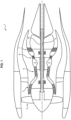
- a dual-flow axial turbojet engine is shown schematically on the figure 1 .
- the turbojet 1 comprises, in the direction of air flow along the axis of the engine, a fan 2, a low pressure compressor 3, a high pressure compressor 4, a combustion chamber 5, a high pressure turbine 6, a turbine low pressure 7 and a propulsive nozzle (not shown).
- the fan 1 and the low pressure compressor 3 are connected to the low pressure turbine 7 by a first transmission shaft 9, while the high pressure compressor 4 and the high pressure turbine 6 are connected by a second transmission shaft 10.
- a flow of compressed air by the low and high pressure compressors 3 and 4 feeds combustion in the combustion chamber 5.
- the turbines 6.7 recover kinetic energy from the expansion of the combustion gases before to return it to the compressors 3,4 and the fan 2 via the transmission shafts 9,10.
- the low-pressure turbine shaft 9 is housed inside a journal 11 which terminates the shaft of the low-pressure compressor 3.
- the journal 11 and the portion of the shaft 9 which is located at the level of the trunnion 11 comprises complementary rectilinear splines 12. These complementary splines 12 ensure the transmission of torque between the two parts which constitute the turbine shaft 9 and the shaft of the low-pressure compressor 3.
- the transmission of axial forces between these two parts 9 and 3 is ensured by a thread and nut assembly.
- the shaft 9 ends in a threaded portion 15, the external thread of which cooperates with a nut with internal thread 14.
- Said nut ensures the tightening of an internal annular heel 3a of the low pressure compressor 3 against a wedge of adjustment 13.
- Said wedge 13 is itself interposed between said heel 3a and a stop 9b which the shaft 9 presents upstream of the splines 12.
- a stop ring 16 is also provided to ensure the rotation of the nut is blocked .
- the low-pressure turbine shaft 9 and the compressor shaft 3 are of great length and subjected to significant torques during the operation of the turbojet 1.
- the thread plays an essential role in allowing the transmission of axial forces which can reach several hundred kN.
- the mechanical strength of the threads is therefore critical because the intensity of the forces transmitted causes very significant stresses in very small areas, particularly in the first thread (zone 17 on the figure 2 ). This makes the sizing of this assembly complicated.
- the first thread is therefore generally the most loaded with effort while the stresses decrease rapidly in the following threads.
- This situation causes rapid wear of the first thread (zone 17) and leads to a short lifespan of the parts which must be oversized to achieve the lifespan objective of the assembly.
- the document US 5,537,814 A1 describes an assembly of two parts of a turbomachine using threads having different thread pitches.
- the document US 2001/0002963 A1 describes a holding of two parts by thread cooperation, in which the thread of one of the parts varies.
- the document US 2013/0259599 A1 describes a holding of two parts by thread cooperation, in which the rigidity of a thread is reduced near one end of the thread.
- Variable pitch screws are already known in fields other than that of turbomachines.
- Such screws are for example endless screws used in measuring systems or precision machining machines to adjust the functional clearance of the measuring screw and allow maximum precision in the axial movement of the screw when it is used. turn.
- An aim of the invention is to propose a mechanical assembly for the transmission of axial forces between at least two rotor parts of a turbomachine, which makes it possible to overcome the disadvantages of a threaded turbomachine transmission shaft.
- Another aim of the invention is to limit the excess mass necessary to ensure the mechanical strength of the net.
- Another aim of the invention is to propose, in the context of the assembly of turbomachine rotor parts, a solution which improves the distribution of mechanical stresses on the threaded portions or the engaged nuts and which improves the mechanical strength and the lifespan of said threaded portions and nuts by optimizing the mass.
- Yet another aim of the invention is to propose a production method perfectly suited to the proposed solution.
- the invention proposes a mechanical assembly comprising two rotor parts of a turbomachine, one of the parts being a compressor shaft, the other part being a turbine shaft at least one of these parts being a shaft of the rotor and having a portion with external thread, said assembly further comprising, for the transmission of axial forces between these two parts, a nut with internal thread capable of cooperating with said external thread to block axially by tightening the other part in relation to the first part and allow the transmission of axial forces between these two pieces.
- the pitch variation from one thread to another along the axial dimension of the thread is constant.
- the pitch of the external thread and/or the pitch of the nut varies along the axial dimension of the thread, the space between the thread of said external thread and the thread of the nut gradually decreasing from the first thread to the thread rear in the expected direction for the axial force.
- the stress is no longer borne mainly by the first thread, but is also distributed to the other threads of the thread.
- the invention proposes a method of producing a variable pitch thread of a threaded portion or of a nut of such an assembly.
- the part whose thread pitch must be made variable is gradually immersed in an etching bath.
- the invention further relates to a turbomachine comprising at least two rotor parts assembled by an assembly of the type of that claimed, said assembly further comprising a set of splines for the transmission of torque between these two parts.
- turbomachine for example an aircraft turbine engine.
- This turbomachine is for example, but not limited to, a turbomachine of the type of that of the figure 1 already described.
- the two assembled parts are a turbine shaft and a compressor shaft.
- references 14 and 15 already introduced in figure 2 designate respectively the nut and the threaded portion of such an assembly.
- the threaded portion 15 has a pitch which varies along the axial dimension (arrow Ax in the figure) of the threads.
- the thickness of the thread increases along said axial coast Ax in the direction from which the axial force comes (in this case, in the example in the figure, from downstream to upstream - arrow F ).
- the threads intended to be on the side of the inner annular heel 3a of the low pressure compressor 3 and the stop 9b that the shaft 9 presents are less thick than the threads intended to be furthest away from it.
- This geometry is particularly suitable for producing variable pitch threads. It helps reduce constraints at the bottom of the net.
- the number of threads of a thread involved in an assembly of rotor parts of a turbomachine is around ten (greater than eight, for example equal to twelve).
- the pitch variation is for example of an order of magnitude of a few micrometers.
- the pitch variation Vp is advantageously between 1 and 5 ⁇ m/step, preferably greater than 2 ⁇ m/step, for example equal to 3 ⁇ m/step or beyond.
- the pitch variation is less than the accepted tolerance on the pitch of a thread in this type of application, said tolerance being of the order of several tens of ⁇ m (the pitch of the threads being of the order of a few tenths of a millimeter).
- this reduction can be obtained by varying the pitch of the thread of the nut or by varying the pitch of both the thread of the threaded portion of the shaft and the thread of the nut.
- variable pitch threading can be carried out mechanically.
- the part whose thread must be made variable (part 15 in this case) is gradually immersed in an attack bath 18.
- the speed of progression is adapted to obtain the desired variation in thickness on the threads (referenced 19a to 19c).
- Each thread 19a to 19c is thus immersed in the bath for a period which is adapted to dissolve the material and gradually remove the desired excess thickness for each turn of the thread.
- the non-immersed threads 19a have the nominal profile of the initial threaded part.
- the intermediate threads 19b are thinner than the nominal profile.
- the speed of progression in the acid bath is constant.
- the part is taken out and rinsed and dried the external thread 15 or the nut 14 in order to eliminate chemical residues.
- a mask can be applied to areas of thread that are not desired to be stripped during this process.
- the mask can be applied to the set of threads of the threaded portion 15, except on the force recovery faces (threads numbers 1 and 2 of curves V p1 and V p3 on the figure 5 ).
- the mask is removed after the rinsing step.
- the changes in stresses are the most significant for the first thread (F1 thread with standardized N profile): the stresses decrease when the pitch variation is increased (along the Ax axis): 1776 MPa for the nominal case, 1550 MPa for 1 ⁇ m/step, 1249 MPa for 3 ⁇ m/step.
- This reduction in stresses presents a 30% reduction in the stresses supported by the first thread when we compare the case of 3 ⁇ m/step in relation to the nominal case.
- the proposed production process also has the advantage of making it possible to reduce unacceptable non-conformities in production (more robust manufacturing).
Landscapes
- Engineering & Computer Science (AREA)
- General Engineering & Computer Science (AREA)
- Mechanical Engineering (AREA)
- Structures Of Non-Positive Displacement Pumps (AREA)
- Turbine Rotor Nozzle Sealing (AREA)
Claims (10)
- Mechanische Anordnung, aufweisend zwei Rotorteile (3, 9) einer Turbomaschine, wobei das eine der Teile eine Kompressorwelle ist, wobei das andere Teil eine Turbinenwelle ist, wobei mindestens das eine (9) von diesen Teilen einen Abschnitt mit Außengewinde (15) aufweist, wobei die Anordnung ferner für die Übertragung von Axialkräften zwischen diesen zwei Teilen eine Mutter (14) mit Innengewinde aufweist, das imstande ist, mit dem Außengewinde zusammenzuwirken, um das andere Teil im Verhältnis zum ersten Teil axial durch Spannen zu arretieren und die Übertragung axialer Kräfte zwischen diesen zwei Teilen zu gestatten, dadurch gekennzeichnet, dass die Steigung des Außengewindes (15) und/oder die Steigung der Mutter (14) entlang des Axialmaßes (Ax) des Gewindes variiert/variieren, wobei sich der Raum zwischen dem Gewindegang des Außengewindes (15) und dem Gewindegang der Mutter (14) nach und nach vom ersten Gewindegang zum hinteren Gewindegang in der für die axiale Kraft (F) erwartete Richtung verringert, und dadurch gekennzeichnet, dass die Steigungsvariation (Vp) von einem Gewindegang zu einem anderen entlang des Axialmaßes des Gewindes konstant ist.
- Anordnung nach Anspruch 1, dadurch gekennzeichnet, dass ein Gewinde mit variabler Steigung einen asymmetrischen trapezförmigen Querschnitt von 45° hat.
- Anordnung nach Anspruch 1, dadurch gekennzeichnet, dass die Steigungsvariation (Vp) von einem Gewindegang zu einem anderen kleiner als die Gewindesteigungstoleranz ist.
- Anordnung nach Anspruch 1, dadurch gekennzeichnet, dass der Gewindeabschnitt einen Durchmesser hat, der zwischen 45 und 90 mm liegt, und dass die Steigungsvariation Vp zwischen 1 und 5 um/Steigung liegt.
- Anordnung nach Anspruch 4, dadurch gekennzeichnet, dass die Steigungsvariation größer als 2 um/Steigung ist.
- Anordnung nach Anspruch 1, wobei das Teil mit Gewindeabschnitt die Kompressorwelle ist, wohingegen das andere Teil die Turbinenwelle ist.
- Verfahren zur Herstellung eines Gewindes mit variabler Steigung eines Gewindeabschnitts oder einer Mutter einer Anordnung nach einem der vorangehenden Ansprüche, wobei das Teil (15), dessen Gewindesteigung variabel gemacht werden muss, nach und nach in ein Ätzbad (18) eingetaucht wird.
- Verfahren nach Anspruch 7, wobei die Progressionsgeschwindigkeit im Ätzbad konstant ist.
- Turbomaschine (1), dadurch gekennzeichnet, dass mindestens zwei Rotorteile (3, 9) anhand einer Anordnung nach einem der Ansprüche 1 bis 6 zusammengebaut sind, wobei die Anordnung ferner ein Riffelspiel (12) für die Übertragung von Kraftmoment zwischen diesen zwei Teilen aufweist.
- Flugzeug, dadurch gekennzeichnet, dass es mindestens einen Motor aufweist, der eine Turbomaschine nach Anspruch 9 ist.
Applications Claiming Priority (2)
| Application Number | Priority Date | Filing Date | Title |
|---|---|---|---|
| FR1857321A FR3084701B1 (fr) | 2018-08-06 | 2018-08-06 | Assemblage mecanique pour la transmission d'efforts axiaux entre au moins deux pieces de rotor d'une turbomachine et procede de realisation d'un filetage variable pour un tel assemblage. |
| PCT/FR2019/051902 WO2020030873A1 (fr) | 2018-08-06 | 2019-08-05 | Assemblage mécanique pour la transmission d'efforts axiaux entre au moins deux pièces de rotor d'une turbomachine et procédé de réalisation d'un filetage variable pour un tel assemblage |
Publications (2)
| Publication Number | Publication Date |
|---|---|
| EP3833853A1 EP3833853A1 (de) | 2021-06-16 |
| EP3833853B1 true EP3833853B1 (de) | 2023-09-27 |
Family
ID=64049388
Family Applications (1)
| Application Number | Title | Priority Date | Filing Date |
|---|---|---|---|
| EP19759665.3A Active EP3833853B1 (de) | 2018-08-06 | 2019-08-05 | Mechanische anordnung zur übertragung von axialkräften zwischen mindestens zwei rotorteilen einer turbomaschine und verfahren zur herstellung eines variablen gewindes für eine solche anordnung |
Country Status (5)
| Country | Link |
|---|---|
| US (1) | US12546222B2 (de) |
| EP (1) | EP3833853B1 (de) |
| CN (1) | CN112534118B (de) |
| FR (1) | FR3084701B1 (de) |
| WO (1) | WO2020030873A1 (de) |
Families Citing this family (4)
| Publication number | Priority date | Publication date | Assignee | Title |
|---|---|---|---|---|
| FR3145380B1 (fr) * | 2023-01-27 | 2025-02-21 | Safran Aircraft Engines | Turbomachine d’aeronef a jonc d’arret de fourreau de protection |
| FR3147321A1 (fr) * | 2023-03-28 | 2024-10-04 | Safran Aircraft Engines | Dispositif de calage axial d’un rotor sur un stator d’une turbine |
| FR3157469A1 (fr) * | 2023-12-20 | 2025-06-27 | Safran Aircraft Engines | Turbomachine comprenant plusieurs modules et un dispositif de blocage de ces modules, et procede de montage correspondant |
| FR3162797A1 (fr) * | 2024-06-03 | 2025-12-05 | Safran Aircraft Engines | Turbomachine comprenant plusieurs modules et un dispositif de blocage de ces modules, et procede de montage correspondant |
Family Cites Families (9)
| Publication number | Priority date | Publication date | Assignee | Title |
|---|---|---|---|---|
| GB2074280A (en) * | 1980-04-02 | 1981-10-28 | Sparling L G M | Screw Thread Fasteners |
| US5537814A (en) * | 1994-09-28 | 1996-07-23 | General Electric Company | High pressure gas generator rotor tie rod system for gas turbine engine |
| US5779416A (en) * | 1996-10-30 | 1998-07-14 | General Electric Co. | Bolt/stud and nut for enhanced high-cycle fatigue capability |
| WO2000000750A1 (de) * | 1998-06-26 | 2000-01-06 | Siemens Aktiengesellschaft | Gewinde sowie schraubverbindung für eine hohe anwendungstemperatur |
| US6848724B2 (en) * | 2002-08-12 | 2005-02-01 | Grant Prideco, Inc. | Thread design for uniform distribution of makeup forces |
| FR2963062B1 (fr) * | 2010-07-20 | 2012-08-31 | Snecma | Assemblage entre un tourillon d'arbre de compresseur et un pignon conique pour l'entrainement d'un boitier d'accessoires d'une turbomachine |
| FR2975449B1 (fr) * | 2011-05-17 | 2015-11-13 | Snecma | Dispositif de fixation d'une piece annulaire sur un arbre de turbomachine |
| US8882425B2 (en) * | 2012-04-02 | 2014-11-11 | United Technologies Corporation | Thread load distribution |
| FR2993658B1 (fr) * | 2012-07-19 | 2015-05-01 | Snecma | Procede d'equilibrage de rotor de turbomachine |
-
2018
- 2018-08-06 FR FR1857321A patent/FR3084701B1/fr active Active
-
2019
- 2019-08-05 CN CN201980052091.4A patent/CN112534118B/zh active Active
- 2019-08-05 US US17/266,202 patent/US12546222B2/en active Active
- 2019-08-05 EP EP19759665.3A patent/EP3833853B1/de active Active
- 2019-08-05 WO PCT/FR2019/051902 patent/WO2020030873A1/fr not_active Ceased
Also Published As
| Publication number | Publication date |
|---|---|
| FR3084701A1 (fr) | 2020-02-07 |
| CN112534118A (zh) | 2021-03-19 |
| CN112534118B (zh) | 2023-04-14 |
| FR3084701B1 (fr) | 2020-12-04 |
| EP3833853A1 (de) | 2021-06-16 |
| US12546222B2 (en) | 2026-02-10 |
| WO2020030873A1 (fr) | 2020-02-13 |
| US20210262347A1 (en) | 2021-08-26 |
Similar Documents
| Publication | Publication Date | Title |
|---|---|---|
| WO2020030873A1 (fr) | Assemblage mécanique pour la transmission d'efforts axiaux entre au moins deux pièces de rotor d'une turbomachine et procédé de réalisation d'un filetage variable pour un tel assemblage | |
| CA2634986C (fr) | Montage d'un arbre dans un palier avec un ecrou auto extracteur | |
| EP3004554B1 (de) | Rotorscheibenschaufel für turbomaschine, turbomaschinen-rotorscheibe, turbomaschine und verfahren zur montage von platten auf einen schaufelfuss | |
| EP1481756B1 (de) | Verfahren zur Herstellung einer hohlen Turbinenschaufel | |
| FR2979968A1 (fr) | Ensemble pour la realisation d'un joint filete pour le forage et l'exploitation des puits d'hydrocarbures et joint filete resultant | |
| EP2836681A1 (de) | Kopplung von wellen anhand von keilverzahnungen mit variablem profil | |
| EP3464903B1 (de) | Stator, rotierende welle, trockenvakuumpumpe und zugehörige herstellungsverfahren | |
| FR2596472A1 (fr) | Unite d'assemblage allege du type vis-ecrou | |
| WO2012117200A1 (fr) | Procede de realisation d'une piece metallique telle qu'un renfort d'aube de turbomachine | |
| FR2983907A1 (fr) | Procede pour realiser un element de liaison dispose entre deux pieces d'une structure, element de liaison et turbomoteur a double flux comprenant un tel element de liaison. | |
| WO2009141545A1 (fr) | Procede et organe de serrage d'elements de visserie, dispositif de fixation et de serrage | |
| EP3295004B1 (de) | Exzenterbauteil für ein system zur veränderung des kompressionsverhältnisses einer brennkraftmaschine | |
| EP2780605B2 (de) | Selbstverriegelndes befestigungssystem mit schraubgewinden | |
| FR2998932A1 (fr) | Ecrou a bague auto-freinante et procede de fabrication d'un tel ecrou | |
| EP1939409B1 (de) | System zur Verbindung von zwei in etwa röhrenförmigen Elementen, Gehäuse, das ein solches System umfasst, und Verwendung dieses Systems | |
| EP4411178B1 (de) | Strömungsmaschine mit einem drehzahlminderer mit durch eine zahnkupplung gekoppelten befestigungsflanschen | |
| BE1032906B1 (fr) | Ensemble vissé et précontraint présentant une conception améliorée à des fins de maintien des performances sous températures cryogéniques | |
| FR3154138A1 (fr) | Carter porte tige de guidage | |
| FR2981124A1 (fr) | Fourreau de protection d'un arbre de turbomachine | |
| FR3005328A1 (fr) | Procede et outil de fabrication d'une roue pour turbine hydraulique, et turbine hydraulique fabriquee par un tel procede | |
| FR3150254A1 (fr) | Outillage et procede de precharge d’un palier a roulement | |
| WO2025056854A1 (fr) | Ensemble comprenant une aube et un systeme de maintien de l'aube | |
| FR3147246A1 (fr) | Module a helice pour une turbomachine d’aeronef avec un dispositif de mise en drapeau d’aubes a calage variable | |
| FR3147607A1 (fr) | Assemblage comportant au moins une pièce composite et des moyens de fixation | |
| FR3018328A3 (fr) | Differentiel pour vehicule automobile avec dispositif de maintien en position de l'axe porte-satellite |
Legal Events
| Date | Code | Title | Description |
|---|---|---|---|
| STAA | Information on the status of an ep patent application or granted ep patent |
Free format text: STATUS: UNKNOWN |
|
| STAA | Information on the status of an ep patent application or granted ep patent |
Free format text: STATUS: THE INTERNATIONAL PUBLICATION HAS BEEN MADE |
|
| PUAI | Public reference made under article 153(3) epc to a published international application that has entered the european phase |
Free format text: ORIGINAL CODE: 0009012 |
|
| STAA | Information on the status of an ep patent application or granted ep patent |
Free format text: STATUS: REQUEST FOR EXAMINATION WAS MADE |
|
| 17P | Request for examination filed |
Effective date: 20210302 |
|
| AK | Designated contracting states |
Kind code of ref document: A1 Designated state(s): AL AT BE BG CH CY CZ DE DK EE ES FI FR GB GR HR HU IE IS IT LI LT LU LV MC MK MT NL NO PL PT RO RS SE SI SK SM TR |
|
| DAV | Request for validation of the european patent (deleted) | ||
| DAX | Request for extension of the european patent (deleted) | ||
| GRAP | Despatch of communication of intention to grant a patent |
Free format text: ORIGINAL CODE: EPIDOSNIGR1 |
|
| STAA | Information on the status of an ep patent application or granted ep patent |
Free format text: STATUS: GRANT OF PATENT IS INTENDED |
|
| INTG | Intention to grant announced |
Effective date: 20230329 |
|
| GRAS | Grant fee paid |
Free format text: ORIGINAL CODE: EPIDOSNIGR3 |
|
| GRAA | (expected) grant |
Free format text: ORIGINAL CODE: 0009210 |
|
| STAA | Information on the status of an ep patent application or granted ep patent |
Free format text: STATUS: THE PATENT HAS BEEN GRANTED |
|
| AK | Designated contracting states |
Kind code of ref document: B1 Designated state(s): AL AT BE BG CH CY CZ DE DK EE ES FI FR GB GR HR HU IE IS IT LI LT LU LV MC MK MT NL NO PL PT RO RS SE SI SK SM TR |
|
| REG | Reference to a national code |
Ref country code: GB Ref legal event code: FG4D Free format text: NOT ENGLISH |
|
| REG | Reference to a national code |
Ref country code: CH Ref legal event code: EP |
|
| REG | Reference to a national code |
Ref country code: DE Ref legal event code: R096 Ref document number: 602019038246 Country of ref document: DE |
|
| REG | Reference to a national code |
Ref country code: IE Ref legal event code: FG4D Free format text: LANGUAGE OF EP DOCUMENT: FRENCH |
|
| REG | Reference to a national code |
Ref country code: LT Ref legal event code: MG9D |
|
| PG25 | Lapsed in a contracting state [announced via postgrant information from national office to epo] |
Ref country code: GR Free format text: LAPSE BECAUSE OF FAILURE TO SUBMIT A TRANSLATION OF THE DESCRIPTION OR TO PAY THE FEE WITHIN THE PRESCRIBED TIME-LIMIT Effective date: 20231228 |
|
| PG25 | Lapsed in a contracting state [announced via postgrant information from national office to epo] |
Ref country code: SE Free format text: LAPSE BECAUSE OF FAILURE TO SUBMIT A TRANSLATION OF THE DESCRIPTION OR TO PAY THE FEE WITHIN THE PRESCRIBED TIME-LIMIT Effective date: 20230927 Ref country code: RS Free format text: LAPSE BECAUSE OF FAILURE TO SUBMIT A TRANSLATION OF THE DESCRIPTION OR TO PAY THE FEE WITHIN THE PRESCRIBED TIME-LIMIT Effective date: 20230927 Ref country code: NO Free format text: LAPSE BECAUSE OF FAILURE TO SUBMIT A TRANSLATION OF THE DESCRIPTION OR TO PAY THE FEE WITHIN THE PRESCRIBED TIME-LIMIT Effective date: 20231227 Ref country code: LV Free format text: LAPSE BECAUSE OF FAILURE TO SUBMIT A TRANSLATION OF THE DESCRIPTION OR TO PAY THE FEE WITHIN THE PRESCRIBED TIME-LIMIT Effective date: 20230927 Ref country code: LT Free format text: LAPSE BECAUSE OF FAILURE TO SUBMIT A TRANSLATION OF THE DESCRIPTION OR TO PAY THE FEE WITHIN THE PRESCRIBED TIME-LIMIT Effective date: 20230927 Ref country code: HR Free format text: LAPSE BECAUSE OF FAILURE TO SUBMIT A TRANSLATION OF THE DESCRIPTION OR TO PAY THE FEE WITHIN THE PRESCRIBED TIME-LIMIT Effective date: 20230927 Ref country code: GR Free format text: LAPSE BECAUSE OF FAILURE TO SUBMIT A TRANSLATION OF THE DESCRIPTION OR TO PAY THE FEE WITHIN THE PRESCRIBED TIME-LIMIT Effective date: 20231228 Ref country code: FI Free format text: LAPSE BECAUSE OF FAILURE TO SUBMIT A TRANSLATION OF THE DESCRIPTION OR TO PAY THE FEE WITHIN THE PRESCRIBED TIME-LIMIT Effective date: 20230927 |
|
| REG | Reference to a national code |
Ref country code: NL Ref legal event code: MP Effective date: 20230927 |
|
| REG | Reference to a national code |
Ref country code: AT Ref legal event code: MK05 Ref document number: 1615616 Country of ref document: AT Kind code of ref document: T Effective date: 20230927 |
|
| PG25 | Lapsed in a contracting state [announced via postgrant information from national office to epo] |
Ref country code: NL Free format text: LAPSE BECAUSE OF FAILURE TO SUBMIT A TRANSLATION OF THE DESCRIPTION OR TO PAY THE FEE WITHIN THE PRESCRIBED TIME-LIMIT Effective date: 20230927 |
|
| PG25 | Lapsed in a contracting state [announced via postgrant information from national office to epo] |
Ref country code: IS Free format text: LAPSE BECAUSE OF FAILURE TO SUBMIT A TRANSLATION OF THE DESCRIPTION OR TO PAY THE FEE WITHIN THE PRESCRIBED TIME-LIMIT Effective date: 20240127 |
|
| PG25 | Lapsed in a contracting state [announced via postgrant information from national office to epo] |
Ref country code: AT Free format text: LAPSE BECAUSE OF FAILURE TO SUBMIT A TRANSLATION OF THE DESCRIPTION OR TO PAY THE FEE WITHIN THE PRESCRIBED TIME-LIMIT Effective date: 20230927 |
|
| PG25 | Lapsed in a contracting state [announced via postgrant information from national office to epo] |
Ref country code: ES Free format text: LAPSE BECAUSE OF FAILURE TO SUBMIT A TRANSLATION OF THE DESCRIPTION OR TO PAY THE FEE WITHIN THE PRESCRIBED TIME-LIMIT Effective date: 20230927 |
|
| PG25 | Lapsed in a contracting state [announced via postgrant information from national office to epo] |
Ref country code: SM Free format text: LAPSE BECAUSE OF FAILURE TO SUBMIT A TRANSLATION OF THE DESCRIPTION OR TO PAY THE FEE WITHIN THE PRESCRIBED TIME-LIMIT Effective date: 20230927 Ref country code: RO Free format text: LAPSE BECAUSE OF FAILURE TO SUBMIT A TRANSLATION OF THE DESCRIPTION OR TO PAY THE FEE WITHIN THE PRESCRIBED TIME-LIMIT Effective date: 20230927 Ref country code: IS Free format text: LAPSE BECAUSE OF FAILURE TO SUBMIT A TRANSLATION OF THE DESCRIPTION OR TO PAY THE FEE WITHIN THE PRESCRIBED TIME-LIMIT Effective date: 20240127 Ref country code: ES Free format text: LAPSE BECAUSE OF FAILURE TO SUBMIT A TRANSLATION OF THE DESCRIPTION OR TO PAY THE FEE WITHIN THE PRESCRIBED TIME-LIMIT Effective date: 20230927 Ref country code: EE Free format text: LAPSE BECAUSE OF FAILURE TO SUBMIT A TRANSLATION OF THE DESCRIPTION OR TO PAY THE FEE WITHIN THE PRESCRIBED TIME-LIMIT Effective date: 20230927 Ref country code: CZ Free format text: LAPSE BECAUSE OF FAILURE TO SUBMIT A TRANSLATION OF THE DESCRIPTION OR TO PAY THE FEE WITHIN THE PRESCRIBED TIME-LIMIT Effective date: 20230927 Ref country code: AT Free format text: LAPSE BECAUSE OF FAILURE TO SUBMIT A TRANSLATION OF THE DESCRIPTION OR TO PAY THE FEE WITHIN THE PRESCRIBED TIME-LIMIT Effective date: 20230927 Ref country code: PT Free format text: LAPSE BECAUSE OF FAILURE TO SUBMIT A TRANSLATION OF THE DESCRIPTION OR TO PAY THE FEE WITHIN THE PRESCRIBED TIME-LIMIT Effective date: 20240129 Ref country code: SK Free format text: LAPSE BECAUSE OF FAILURE TO SUBMIT A TRANSLATION OF THE DESCRIPTION OR TO PAY THE FEE WITHIN THE PRESCRIBED TIME-LIMIT Effective date: 20230927 |
|
| PG25 | Lapsed in a contracting state [announced via postgrant information from national office to epo] |
Ref country code: PL Free format text: LAPSE BECAUSE OF FAILURE TO SUBMIT A TRANSLATION OF THE DESCRIPTION OR TO PAY THE FEE WITHIN THE PRESCRIBED TIME-LIMIT Effective date: 20230927 Ref country code: IT Free format text: LAPSE BECAUSE OF FAILURE TO SUBMIT A TRANSLATION OF THE DESCRIPTION OR TO PAY THE FEE WITHIN THE PRESCRIBED TIME-LIMIT Effective date: 20230927 |
|
| REG | Reference to a national code |
Ref country code: DE Ref legal event code: R097 Ref document number: 602019038246 Country of ref document: DE |
|
| PG25 | Lapsed in a contracting state [announced via postgrant information from national office to epo] |
Ref country code: DK Free format text: LAPSE BECAUSE OF FAILURE TO SUBMIT A TRANSLATION OF THE DESCRIPTION OR TO PAY THE FEE WITHIN THE PRESCRIBED TIME-LIMIT Effective date: 20230927 |
|
| PG25 | Lapsed in a contracting state [announced via postgrant information from national office to epo] |
Ref country code: DK Free format text: LAPSE BECAUSE OF FAILURE TO SUBMIT A TRANSLATION OF THE DESCRIPTION OR TO PAY THE FEE WITHIN THE PRESCRIBED TIME-LIMIT Effective date: 20230927 |
|
| PLBE | No opposition filed within time limit |
Free format text: ORIGINAL CODE: 0009261 |
|
| STAA | Information on the status of an ep patent application or granted ep patent |
Free format text: STATUS: NO OPPOSITION FILED WITHIN TIME LIMIT |
|
| 26N | No opposition filed |
Effective date: 20240628 |
|
| PG25 | Lapsed in a contracting state [announced via postgrant information from national office to epo] |
Ref country code: SI Free format text: LAPSE BECAUSE OF FAILURE TO SUBMIT A TRANSLATION OF THE DESCRIPTION OR TO PAY THE FEE WITHIN THE PRESCRIBED TIME-LIMIT Effective date: 20230927 |
|
| PG25 | Lapsed in a contracting state [announced via postgrant information from national office to epo] |
Ref country code: SI Free format text: LAPSE BECAUSE OF FAILURE TO SUBMIT A TRANSLATION OF THE DESCRIPTION OR TO PAY THE FEE WITHIN THE PRESCRIBED TIME-LIMIT Effective date: 20230927 |
|
| PG25 | Lapsed in a contracting state [announced via postgrant information from national office to epo] |
Ref country code: BG Free format text: LAPSE BECAUSE OF FAILURE TO SUBMIT A TRANSLATION OF THE DESCRIPTION OR TO PAY THE FEE WITHIN THE PRESCRIBED TIME-LIMIT Effective date: 20230927 |
|
| PG25 | Lapsed in a contracting state [announced via postgrant information from national office to epo] |
Ref country code: BG Free format text: LAPSE BECAUSE OF FAILURE TO SUBMIT A TRANSLATION OF THE DESCRIPTION OR TO PAY THE FEE WITHIN THE PRESCRIBED TIME-LIMIT Effective date: 20230927 |
|
| REG | Reference to a national code |
Ref country code: CH Ref legal event code: PL |
|
| PG25 | Lapsed in a contracting state [announced via postgrant information from national office to epo] |
Ref country code: LU Free format text: LAPSE BECAUSE OF NON-PAYMENT OF DUE FEES Effective date: 20240805 |
|
| PG25 | Lapsed in a contracting state [announced via postgrant information from national office to epo] |
Ref country code: MC Free format text: LAPSE BECAUSE OF FAILURE TO SUBMIT A TRANSLATION OF THE DESCRIPTION OR TO PAY THE FEE WITHIN THE PRESCRIBED TIME-LIMIT Effective date: 20230927 Ref country code: CH Free format text: LAPSE BECAUSE OF NON-PAYMENT OF DUE FEES Effective date: 20240831 |
|
| REG | Reference to a national code |
Ref country code: BE Ref legal event code: MM Effective date: 20240831 |
|
| PG25 | Lapsed in a contracting state [announced via postgrant information from national office to epo] |
Ref country code: BE Free format text: LAPSE BECAUSE OF NON-PAYMENT OF DUE FEES Effective date: 20240831 |
|
| PG25 | Lapsed in a contracting state [announced via postgrant information from national office to epo] |
Ref country code: IE Free format text: LAPSE BECAUSE OF NON-PAYMENT OF DUE FEES Effective date: 20240805 |
|
| PGFP | Annual fee paid to national office [announced via postgrant information from national office to epo] |
Ref country code: DE Payment date: 20250819 Year of fee payment: 7 |
|
| PGFP | Annual fee paid to national office [announced via postgrant information from national office to epo] |
Ref country code: GB Payment date: 20250825 Year of fee payment: 7 |
|
| PGFP | Annual fee paid to national office [announced via postgrant information from national office to epo] |
Ref country code: FR Payment date: 20250827 Year of fee payment: 7 |
|
| PG25 | Lapsed in a contracting state [announced via postgrant information from national office to epo] |
Ref country code: CY Free format text: LAPSE BECAUSE OF FAILURE TO SUBMIT A TRANSLATION OF THE DESCRIPTION OR TO PAY THE FEE WITHIN THE PRESCRIBED TIME-LIMIT; INVALID AB INITIO Effective date: 20190805 |
|
| PG25 | Lapsed in a contracting state [announced via postgrant information from national office to epo] |
Ref country code: HU Free format text: LAPSE BECAUSE OF FAILURE TO SUBMIT A TRANSLATION OF THE DESCRIPTION OR TO PAY THE FEE WITHIN THE PRESCRIBED TIME-LIMIT; INVALID AB INITIO Effective date: 20190805 |