EP3833552B1 - Tyre tread - Google Patents
Tyre tread Download PDFInfo
- Publication number
- EP3833552B1 EP3833552B1 EP19753011.6A EP19753011A EP3833552B1 EP 3833552 B1 EP3833552 B1 EP 3833552B1 EP 19753011 A EP19753011 A EP 19753011A EP 3833552 B1 EP3833552 B1 EP 3833552B1
- Authority
- EP
- European Patent Office
- Prior art keywords
- tread
- channels
- radial openings
- blocking devices
- channel
- Prior art date
- Legal status (The legal status is an assumption and is not a legal conclusion. Google has not performed a legal analysis and makes no representation as to the accuracy of the status listed.)
- Active
Links
Images

Classifications
-
- B—PERFORMING OPERATIONS; TRANSPORTING
- B60—VEHICLES IN GENERAL
- B60C—VEHICLE TYRES; TYRE INFLATION; TYRE CHANGING; CONNECTING VALVES TO INFLATABLE ELASTIC BODIES IN GENERAL; DEVICES OR ARRANGEMENTS RELATED TO TYRES
- B60C11/00—Tyre tread bands; Tread patterns; Anti-skid inserts
- B60C11/03—Tread patterns
- B60C11/13—Tread patterns characterised by the groove cross-section, e.g. for buttressing or preventing stone-trapping
- B60C11/1369—Tie bars for linking block elements and bridging the groove
-
- B—PERFORMING OPERATIONS; TRANSPORTING
- B60—VEHICLES IN GENERAL
- B60C—VEHICLE TYRES; TYRE INFLATION; TYRE CHANGING; CONNECTING VALVES TO INFLATABLE ELASTIC BODIES IN GENERAL; DEVICES OR ARRANGEMENTS RELATED TO TYRES
- B60C11/00—Tyre tread bands; Tread patterns; Anti-skid inserts
- B60C11/03—Tread patterns
- B60C11/032—Patterns comprising isolated recesses
- B60C11/0323—Patterns comprising isolated recesses tread comprising channels under the tread surface, e.g. for draining water
-
- B—PERFORMING OPERATIONS; TRANSPORTING
- B60—VEHICLES IN GENERAL
- B60C—VEHICLE TYRES; TYRE INFLATION; TYRE CHANGING; CONNECTING VALVES TO INFLATABLE ELASTIC BODIES IN GENERAL; DEVICES OR ARRANGEMENTS RELATED TO TYRES
- B60C11/00—Tyre tread bands; Tread patterns; Anti-skid inserts
- B60C11/03—Tread patterns
- B60C11/12—Tread patterns characterised by the use of narrow slits or incisions, e.g. sipes
- B60C11/1236—Tread patterns characterised by the use of narrow slits or incisions, e.g. sipes with special arrangements in the tread pattern
-
- B—PERFORMING OPERATIONS; TRANSPORTING
- B60—VEHICLES IN GENERAL
- B60C—VEHICLE TYRES; TYRE INFLATION; TYRE CHANGING; CONNECTING VALVES TO INFLATABLE ELASTIC BODIES IN GENERAL; DEVICES OR ARRANGEMENTS RELATED TO TYRES
- B60C11/00—Tyre tread bands; Tread patterns; Anti-skid inserts
- B60C11/03—Tread patterns
- B60C11/12—Tread patterns characterised by the use of narrow slits or incisions, e.g. sipes
- B60C11/1259—Depth of the sipe
-
- B—PERFORMING OPERATIONS; TRANSPORTING
- B60—VEHICLES IN GENERAL
- B60C—VEHICLE TYRES; TYRE INFLATION; TYRE CHANGING; CONNECTING VALVES TO INFLATABLE ELASTIC BODIES IN GENERAL; DEVICES OR ARRANGEMENTS RELATED TO TYRES
- B60C11/00—Tyre tread bands; Tread patterns; Anti-skid inserts
- B60C11/03—Tread patterns
- B60C11/12—Tread patterns characterised by the use of narrow slits or incisions, e.g. sipes
- B60C11/1272—Width of the sipe
- B60C11/1281—Width of the sipe different within the same sipe, i.e. enlarged width portion at sipe bottom or along its length
-
- B—PERFORMING OPERATIONS; TRANSPORTING
- B60—VEHICLES IN GENERAL
- B60C—VEHICLE TYRES; TYRE INFLATION; TYRE CHANGING; CONNECTING VALVES TO INFLATABLE ELASTIC BODIES IN GENERAL; DEVICES OR ARRANGEMENTS RELATED TO TYRES
- B60C11/00—Tyre tread bands; Tread patterns; Anti-skid inserts
- B60C11/03—Tread patterns
- B60C11/13—Tread patterns characterised by the groove cross-section, e.g. for buttressing or preventing stone-trapping
- B60C11/1307—Tread patterns characterised by the groove cross-section, e.g. for buttressing or preventing stone-trapping with special features of the groove walls
- B60C11/1315—Tread patterns characterised by the groove cross-section, e.g. for buttressing or preventing stone-trapping with special features of the groove walls having variable inclination angles, e.g. warped groove walls
-
- B—PERFORMING OPERATIONS; TRANSPORTING
- B60—VEHICLES IN GENERAL
- B60C—VEHICLE TYRES; TYRE INFLATION; TYRE CHANGING; CONNECTING VALVES TO INFLATABLE ELASTIC BODIES IN GENERAL; DEVICES OR ARRANGEMENTS RELATED TO TYRES
- B60C11/00—Tyre tread bands; Tread patterns; Anti-skid inserts
- B60C11/03—Tread patterns
- B60C2011/0337—Tread patterns characterised by particular design features of the pattern
- B60C2011/0339—Grooves
- B60C2011/0358—Lateral grooves, i.e. having an angle of 45 to 90 degees to the equatorial plane
- B60C2011/036—Narrow grooves, i.e. having a width of less than 3 mm
-
- B—PERFORMING OPERATIONS; TRANSPORTING
- B60—VEHICLES IN GENERAL
- B60C—VEHICLE TYRES; TYRE INFLATION; TYRE CHANGING; CONNECTING VALVES TO INFLATABLE ELASTIC BODIES IN GENERAL; DEVICES OR ARRANGEMENTS RELATED TO TYRES
- B60C11/00—Tyre tread bands; Tread patterns; Anti-skid inserts
- B60C11/03—Tread patterns
- B60C11/13—Tread patterns characterised by the groove cross-section, e.g. for buttressing or preventing stone-trapping
- B60C11/1307—Tread patterns characterised by the groove cross-section, e.g. for buttressing or preventing stone-trapping with special features of the groove walls
- B60C2011/1338—Tread patterns characterised by the groove cross-section, e.g. for buttressing or preventing stone-trapping with special features of the groove walls comprising protrusions
-
- B—PERFORMING OPERATIONS; TRANSPORTING
- B60—VEHICLES IN GENERAL
- B60C—VEHICLE TYRES; TYRE INFLATION; TYRE CHANGING; CONNECTING VALVES TO INFLATABLE ELASTIC BODIES IN GENERAL; DEVICES OR ARRANGEMENTS RELATED TO TYRES
- B60C2200/00—Tyres specially adapted for particular applications
- B60C2200/06—Tyres specially adapted for particular applications for heavy duty vehicles
Definitions
- the invention relates to treads for tires and more particularly to the tread patterns of these treads, the performance of which in terms of water drainage in rainy weather is made more durable, these treads also having improved performance in wear ; this invention also relates to tires provided with such bands.
- the conditions of driving in rainy weather of a heavy vehicle require rapid evacuation of the water which may be found in the region of contact of the tire or more particularly of its tread with the roadway.
- the evacuation of the water makes it possible to ensure contact of the material constituting the tread with this roadway. Water that is not pushed out to the front and sides of the tire drains or is partially captured in the cutouts or depressions formed in the tread of the tire.
- cutouts or hollows form a fluid flow network which must be durable, i.e. be effective throughout the service life of a tire between its new condition and its removal due to damage. wear reaching a limit set by the manufacturer in accordance with the regulations in force.
- circumferential grooves or longitudinal grooves
- this total thickness not taking into account the thickness possibly provided to allow partial renewal of the grooves by a so-called regrooving operation.
- longitudinal grooves make it possible to obtain a tread having a water drainage performance which is always above a minimum performance called safety performance and this regardless of the level of wear of this tread. within the limit set by the manufacturer.
- the total hollow-to-new volume is generally between 10% and 25% of the total volume of the tread intended to be worn during travel (this total volume corresponding to the volume of material to be worn to which said total volume of hollows is added). It can be seen that these tires have a hollow volume available in the contact patch which is relatively large when new (volume of hollow available meaning that this volume is potentially likely to be filled in part or in whole by water present on the roadway).
- the volume of hollow opening on the running surface in contact is evaluated when the tire is subjected to its usual inflation and load conditions as defined in particular by the E.T.R.T.O. for Europe. This standard indicates the reference inflation pressure corresponding to the load capacity of the tire indicated by its load index and its speed index. These conditions of use can also be called “nominal conditions” or "conditions of use”.
- cutouts or more generally cavities are essential for the drainage of water in the region of contact with the roadway, the reduction in volume of material which results therefrom on the strip can significantly affect the wear performance of this strip and consequently can reduce the service life of the tire due to an increase in the wear rate of said tread.
- grooves and incisions can be distinguished.
- the incisions unlike the grooves, have an appropriate width so that the facing walls delimiting them come into contact at least partially against each other when passing through the contact area.
- the grooves generate a significant lowering of the compressive and shear rigidities of the tread since these grooves delimit portions of material which can deform much more significantly than the portions delimited by incisions whose walls come into contact with one against each other when passing through the contact area. This reduction in rigidity, in the case of the presence of grooves, induces an increase in deformations and is likely to generate a reduction in the wear performance of the strip.
- the document FR 3 014 022 A1 shows a tread for a heavy-duty vehicle comprising, in new condition, circumferential grooves and transverse channels comprising radial openings alternated with locking devices.
- the tread surface of a tread corresponds to all of the elementary surfaces of the tread that can come into contact with a roadway during the rolling of a tire provided with such a tread.
- radial direction (Z) is meant in the present document a direction which is perpendicular to the axis of rotation of the tire (this direction corresponds to the direction of the thickness of the tread).
- transverse or axial direction is meant a direction parallel to the axis of rotation of the tire.
- circumferential direction or longitudinal direction (X) is meant a direction which is tangent to any circle centered on the axis of rotation. This direction is perpendicular both to the axial direction and to a radial direction.
- a tread has a maximum thickness of material to be worn out (EMU) in rolling defined between the running surface when new and the legal wear limit generally materialized by wear indicators located for example at 1.6 mm from the bottom. tread grooves.
- EMU material to be worn out
- the mid-equatorial plane is a plane perpendicular to the axis of rotation dividing the tire into two equal halves.
- the object of the invention is to provide a tread having improved wear and rolling resistance performance while maintaining good traction and water evacuation performance throughout the use of the tread. tread between its new condition and its removal due to wear reaching the regulatory limit.
- the blocking devices comprise contact faces of length Lc in the direction of the underlying channel, said length Lc being between 10mm and 40mm.
- the radial openings have, in the direction of the underlying channel, a length Lo with Lc ⁇ Lo ⁇ 3 ⁇ Lc.
- the blocking devices have a radial height of between 25% and 75% of the maximum thickness of material to be worn out while driving.
- the locking devices are located at a radial distance from the running surface of between 0 and 5 mm.
- the alternation of the radial openings and the blocking devices of a channel is offset axially with respect to the alternation of the radial openings and the blocking devices of the longitudinally adjacent channel.
- the channels opening onto one side face of the tread are also connected in the middle region of the tread to the channels opening onto the other side face of the tread.
- the channels opening onto one side face of the tread are offset longitudinally in the middle region relative to the channels opening onto the other side face of the tread.
- the tread further comprises shoulder incisions of substantially longitudinal orientation located at a distance Di from the side faces of the tread of between 15% and 25% of the width of the tread.
- said shoulder incisions connect radial openings of longitudinally adjacent channels.
- the tread further comprises central incisions of substantially longitudinal orientation located axially between the shoulder incisions.
- said central incisions connect radial openings of longitudinally adjacent channels.
- said central incisions have a depth greater than 80% of the maximum thickness of material to be worn and preferably a width less than 1.5 mm.
- the invention also relates to a heavy vehicle tire provided with a tread as described previously.
- a tire 2 for a heavy vehicle comprising a tread 1 according to the invention.
- the tread comprises a rolling surface 11, respective side faces 12 and 12' and sculpture elements such as incisions 13 and 14, transverse channels 15, radial openings 16 or transverse grooves 18.
- a tread pattern element such as a channel or a groove is said to be transverse when its general orientation forms an angle equal to or greater than 45 degrees with the longitudinal direction X.
- the tread according to the invention has no circumferential (longitudinal) grooves.
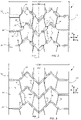
- FIG 2 a front view of a fraction of the tread of the figure 1 on an enlarged scale allowing in particular to better distinguish the elements that make up his sculpture.
- the tread is shown here in new condition.
- the tread is divided into two equal parts by the equatorial median plane PME.
- the median region RM of the tread designates the region located on either side of the equatorial median plane over a width corresponding to 20% of the width Lbdr of the tread.
- the transverse channels 15 are located in the thickness of material to be worn, that is to say under the running surface 11 in the new state of the tread.
- the radial openings 16 connect in the radial direction the transverse channels to the rolling surface 11. At the bottom of the radial openings, we can therefore see the transverse channels 15.
- Blocking devices 17 are interposed between the successive radial openings along the transverse channels .
- the transverse channels 15 which are arranged at the bottom of the tread connect the median region RM of the tread to the side faces 12 and 12' so as to be able to evacuate the water laterally from the contact area. In this embodiment, the channels open on the side faces in transverse grooves 18, 19.
- the alternation of the radial openings and the blocking devices of a channel is offset axially (transversely) with respect to the alternation of the radial openings and the blocking devices of the channel longitudinally adjacent.
- a radial opening is thus substantially facing a blocking device of the adjacent transverse channel and vice versa.
- the partially worn tread shown here still has about 5 mm of hollow, i.e. there is about 3.4 mm of material left to wear down to the legal limit of 1.6 mm, which corresponds to less than 20% of the maximum thickness of material to be worn.
- This figure shows more clearly the remaining part of the transverse channels which connect the middle region to the side faces. The blocking devices and therefore the contours of the radial openings have completely disappeared at this stage of wear.
- the transverse channels being arranged at the bottom of the tread generate open and continuous grooves at the end of wear.
- the channels comprise changes of direction between the median region and the lateral face.
- the maximum longitudinal distance DLM is between 10% and 50% of the width of the tread Lbdr and preferably between 10% and 30%. In the example shown here, the DLM distance is 18.5% of Lbdr.
- the central incisions 13 and the shoulder incisions 14 are substantially longitudinal, their general orientation forming an angle less than or equal to 20° with the longitudinal direction X.
- the shoulder incisions 14 are located at a distance Di from the side faces of the tread, Di being between 15% and 25% of the width Lbdr of the tread.
- the central incisions 13 are located between the respective shoulder incisions 14 , ie in a central zone of the tread representing at least 50% of the width Lbdr.
- the transverse channels not only connect the side faces to the middle region of the tread but also connect the side faces to each other since the channels of the left part of the tread are directly connected to the channels of the right part.
- the tread pattern is directional, ie it is not independent of the direction of rotation of the tire.
- the blocking devices comprise contact faces of length Lc . This length is measured according to the direction of the underlying channel. If the contact faces are not, as here, parallel and rectilinear, but for example curved, the length for which the faces are not separated by more than 1.5 mm from each other will be considered.
- the radial openings have a length Lo. This length is measured in the direction of the underlying channel between two successive blocking devices along the channel. If the contact faces of the blocking devices are not parallel and rectilinear but for example curved, the length for which the faces are more than 1.5 mm apart from each other will be considered.
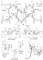
- the figure 5a is a sectional view according to plan AA of the figure 4 mainly showing the first part of the transverse channel connecting the middle region to the right side face of the tread.
- this section shows the alternation of two blocking devices 17 and a radial opening 16 .
- the transverse channel 15 which connects the middle region to the left side face of the tread.
- the first blocking device 17 and the incision 171 which separates the two contact faces opposite the blocking device can clearly be seen.
- the central incision 13 whose radial height (depth) is equivalent to that of the channel.
- the figure 5b is a sectional view according to plan BB of the figure 4 mainly showing the first part of the transverse channel connecting the middle region to the left side face of the tread.
- this section shows the alternation of two radial openings 16 and a blocking device 17.
- the transverse channel 15 which connects the middle region to the right side face of the tread.
- the figure 5c is a sectional view according to the CC plane of the figure 4 showing the transverse channel 15 in a part where it is invisible from the outside due to the presence of the blocking devices 17.
- the width of the transverse channels is between 4 and 10 mm and more preferably between 6 and 8 mm.
- the channel has a width of about 7 mm in its widest part located radially on the outside and of about 5 mm in its radially inside part.
- the blocking devices are, as represented here, part of the contact surface 11 anew, that is to say that they come into contact with the roadway. However, in a manner known per se, they can also be offset below the contact surface, by a radial distance preferably not exceeding 5 mm.
- the radial height HRB of the locking devices preferably represents 25 to 75% of the maximum thickness of material to be worn. In this example, HRB represents approximately 65% of the maximum thickness of material to be worn EMU.
- the figure 5d is a sectional view according to the DD plane of the figure 4 showing a central incision 13.
- the width of the central incisions is here less than 1 mm and their depth (height radial) as indicated above corresponds substantially to the maximum thickness of material to be worn.
- the figure 5e is a sectional view according to the EE plane of the figure 4 showing a shoulder incision 14.
- the width of the shoulder incisions is here about 2.5 mm and their depth corresponds substantially to the maximum thickness of material to be worn.
- an appropriate width for the walls of the incision to come into good contact during its passage through the contact area is between 2 mm and 4 mm.
- the figure 5f is a view of the detail referenced F on the figure 4 showing in particular a radial opening 16 on an even larger scale.
- This view illustrates the angle ⁇ that the distal faces of the locking devices make with the mean direction of the contact faces of said locking devices 17.
- the angle ⁇ is preferably between 90° and 150°.
- ⁇ 1 , ⁇ 2 and ⁇ 3 which are approximately 135° and ⁇ 4 which is approximately 90°.
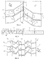
- the figure 6 is a view similar to the figure 4 showing the principles of a second embodiment of a tread according to the invention, the figure 7 being a sectional view along the broken line GG of the figure 6 .
- the transverse channels of the left part of the tread are interspersed with the channels of the right part and are not connected to each other in the middle region.
- Each channel here has a single change of direction between the median region and the lateral face that it connects thereto.
- this embodiment includes shoulder incisions 14, 14' but does not include a central incision.
- Said shoulder incisions connects, depending on the case, two radial openings (configuration of the incision 14) of two adjacent channels or a radial opening to a blocking device 17 (configuration of the incision 14').
- DLM is 20.5% of Lbdr.
- alternation of the radial openings and the blocking devices of a channel is axially offset with respect to the alternation of the radial openings and the blocking devices of the longitudinally adjacent channel so that along a circumferential direction, a radial opening is thus substantially facing a blocking device of the adjacent channel and vice versa.
- the figure 7 also makes it possible to clearly visualize the geometric measurements of the blocking devices (height HRB and length Lc ) and of the radial openings (length Lo).
- the figure 8 is a view similar to the figure 4 showing the principles of a third embodiment of a tread according to the invention.
- the transverse channels of the left part of the tread are again connected to the channels of the right part and therefore connected to each other in the middle region.
- the channels here have three changes of direction between the middle region and the side face which is connected to it.
- this embodiment includes shoulder incisions 14, 14' similar to those of the embodiment of the figure 6 and central incisions 13 similar to those of the embodiment of the figure 4 .
- DLM is 12.5% of Lbdr.
- Another feature of this embodiment is that the pattern is non-directional, ie it is independent of the direction of rotation of the tire.
Landscapes
- Engineering & Computer Science (AREA)
- Mechanical Engineering (AREA)
- Tires In General (AREA)
Description
L'invention concerne les bandes de roulement pour pneus et plus particulièrement les dessins de sculpture de ces bandes dont les performances en drainage de l'eau par temps de pluie sont rendues plus pérennes, ces bandes de roulement ayant en outre des performances améliorées en usure ; cette invention concerne également les pneus pourvus de telles bandes.The invention relates to treads for tires and more particularly to the tread patterns of these treads, the performance of which in terms of water drainage in rainy weather is made more durable, these treads also having improved performance in wear ; this invention also relates to tires provided with such bands.
De façon connue, les conditions de roulage par temps de pluie d'un véhicule poids lourd requièrent une évacuation rapide de l'eau qui peut se trouver dans la région de contact du pneu ou plus particulièrement de sa bande de roulement avec la chaussée. L'évacuation de l'eau permet d'assurer un contact du matériau constituant la bande de roulement avec cette chaussée. L'eau qui n'est pas repoussée sur l'avant et sur les côtés du pneu s'écoule ou est captée en partie dans les découpures ou creux formés dans la bande de roulement du pneu.In a known manner, the conditions of driving in rainy weather of a heavy vehicle require rapid evacuation of the water which may be found in the region of contact of the tire or more particularly of its tread with the roadway. The evacuation of the water makes it possible to ensure contact of the material constituting the tread with this roadway. Water that is not pushed out to the front and sides of the tire drains or is partially captured in the cutouts or depressions formed in the tread of the tire.
Ces découpures ou creux forment un réseau d'écoulement de fluide qui se doit d'être pérenne c'est-à-dire être efficace pendant toute la durée d'utilisation d'un pneu entre son état neuf et son retrait pour cause d'usure atteignant une limite fixée par le manufacturier en accord avec la réglementation en vigueur.These cutouts or hollows form a fluid flow network which must be durable, i.e. be effective throughout the service life of a tire between its new condition and its removal due to damage. wear reaching a limit set by the manufacturer in accordance with the regulations in force.
Pour les pneus destinés aux essieux d'un véhicule poids lourd, il est usuel de former, dans la bande de roulement de ces pneus, des rainures circonférentielles (ou rainures longitudinales) dont la profondeur est égale à l'épaisseur totale de la bande de roulement, cette épaisseur totale ne prenant pas en compte l'épaisseur éventuellement prévue pour permettre un renouvellement partiel des rainures par une opération dite de recreusage (« regrooving » en anglais). De telles rainures longitudinales permettent d'obtenir une bande de roulement ayant une performance en drainage de l'eau qui est toujours au-dessus d'une performance minimale dite performance de sécurité et cela quel que soit le niveau de l'usure de cette bande dans la limite fixée par le manufacturier.For tires intended for the axles of a heavy vehicle, it is customary to form, in the tread of these tires, circumferential grooves (or longitudinal grooves) whose depth is equal to the total thickness of the tread. bearing, this total thickness not taking into account the thickness possibly provided to allow partial renewal of the grooves by a so-called regrooving operation. Such longitudinal grooves make it possible to obtain a tread having a water drainage performance which is always above a minimum performance called safety performance and this regardless of the level of wear of this tread. within the limit set by the manufacturer.
Pour les pneus de l'état de la technique, le volume total de creux à neuf est en règle générale compris entre 10% et 25% du volume total de la bande de roulement destiné à être usé au cours du roulage (ce volume total correspondant au volume de matière à user auquel est ajouté ledit volume total de creux). On constate que ces pneus ont un volume de creux disponible dans l'aire de contact qui est relativement important à l'état neuf (volume de creux disponible signifiant que ce volume est potentiellement susceptible d'être rempli en partie ou en totalité par de l'eau présente sur la chaussée). Le volume de creux s'ouvrant sur la surface de roulement dans le contact est évalué lorsque le pneu est soumis à ses conditions usuelles de gonflage et de charge telles que définies notamment par le règlement E.T.R.T.O. pour l'Europe. Cette norme indique la pression de gonflage de référence correspondant à la capacité de charge du pneu indiquée par son indice de charge et son indice de vitesse. Ces conditions d'utilisation peuvent aussi être dites "conditions nominales" ou "conditions d'usage".For state-of-the-art tyres, the total hollow-to-new volume is generally between 10% and 25% of the total volume of the tread intended to be worn during travel (this total volume corresponding to the volume of material to be worn to which said total volume of hollows is added). It can be seen that these tires have a hollow volume available in the contact patch which is relatively large when new (volume of hollow available meaning that this volume is potentially likely to be filled in part or in whole by water present on the roadway). The volume of hollow opening on the running surface in contact is evaluated when the tire is subjected to its usual inflation and load conditions as defined in particular by the E.T.R.T.O. for Europe. This standard indicates the reference inflation pressure corresponding to the load capacity of the tire indicated by its load index and its speed index. These conditions of use can also be called "nominal conditions" or "conditions of use".
Si des découpures ou plus généralement des cavités sont indispensables au drainage de l'eau dans la région de contact avec la chaussée, la réduction de volume de matière qui en résulte sur la bande peut affecter sensiblement la performance en usure de cette bande et en conséquence peut réduire la durée d'utilisation du pneu du fait d'une augmentation de la vitesse d'usure de ladite bande.If cutouts or more generally cavities are essential for the drainage of water in the region of contact with the roadway, the reduction in volume of material which results therefrom on the strip can significantly affect the wear performance of this strip and consequently can reduce the service life of the tire due to an increase in the wear rate of said tread.
Parmi les découpures qui peuvent être réalisées par moulage dans une bande de roulement, on distingue les rainures et les incisions. Les incisions, à la différence des rainures, ont une largeur appropriée pour que les parois en vis-à-vis les délimitant viennent en contact au moins partiellement l'une contre l'autre lors du passage dans l'aire de contact. Les rainures génèrent un abaissement sensible des rigidités de compression et de cisaillement de la bande de roulement puisque ces rainures délimitent des portions de matière pouvant se déformer de manière beaucoup plus importante que les portions délimitées par des incisions dont les parois viennent en appui l'une contre l'autre lors du passage dans l'aire de contact. Cette diminution de rigidité, dans le cas de la présence de rainures, induit une augmentation des déformations et est susceptible de générer une diminution de la performance en usure de la bande. On observe une usure plus importante pour une distance parcourue fixée et ceci correspond à une augmentation de la vitesse d'usure de la bande. En outre, on constate une augmentation de la résistance au roulement et donc de la consommation des véhicules équipés de tels pneus, résultant d'une augmentation des pertes hystérétiques liées aux cycles de déformations de la matière composant la bande de roulement. Le document
La surface de roulement d'une bande de roulement correspond à l'ensemble des surfaces élémentaires de la bande pouvant venir en contact avec une chaussée lors du roulage d'un pneu pourvu d'une telle bande de roulement.The tread surface of a tread corresponds to all of the elementary surfaces of the tread that can come into contact with a roadway during the rolling of a tire provided with such a tread.
Par direction radiale (Z), on entend dans le présent document une direction qui est perpendiculaire à l'axe de rotation du pneu (cette direction correspond à la direction de l'épaisseur de la bande de roulement).By radial direction (Z), is meant in the present document a direction which is perpendicular to the axis of rotation of the tire (this direction corresponds to the direction of the thickness of the tread).
Par direction transversale ou axiale (Y), on entend une direction parallèle à l'axe de rotation du pneu.By transverse or axial direction (Y) is meant a direction parallel to the axis of rotation of the tire.
Par direction circonférentielle ou direction longitudinale (X), on entend une direction qui est tangente à tout cercle centré sur l'axe de rotation. Cette direction est perpendiculaire à la fois à la direction axiale et à une direction radiale.By circumferential direction or longitudinal direction (X) is meant a direction which is tangent to any circle centered on the axis of rotation. This direction is perpendicular both to the axial direction and to a radial direction.
Une bande de roulement a une épaisseur maximale de matière à user (EMU) en roulage définie entre la surface de roulement à neuf et la limite d'usure légale généralement matérialisée par des témoins d'usure situé par exemple à 1,6 mm du fond des rainures de la bande de roulement.A tread has a maximum thickness of material to be worn out (EMU) in rolling defined between the running surface when new and the legal wear limit generally materialized by wear indicators located for example at 1.6 mm from the bottom. tread grooves.
Le plan médian équatorial (PME) est un plan perpendiculaire à l'axe de rotation divisant le pneu en deux moitiés égales.The mid-equatorial plane (MEP) is a plane perpendicular to the axis of rotation dividing the tire into two equal halves.
Les mesures géométriques des éléments de sculpture dont il est question dans la présente demande sont établies en dehors de l'aire de contact lorsque le pneumatique est monté sur sa jante de référence et gonflé à sa pression de référence dans les conditions d'utilisation définies par la norme E.T.R.T.O.The geometric measurements of the tread pattern elements referred to in the present application are established outside the contact area when the tire is mounted on its reference rim and inflated to its reference pressure under the conditions of use defined by the E.T.R.T.O.
L'objectif de l'invention est de proposer une bande de roulement ayant des performances en usure et en résistance au roulement améliorées tout en maintenant de bonnes performances de traction et d'évacuation de l'eau tout au long de l'usage de la bande de roulement entre son état neuf et son retrait pour cause d'usure atteignant la limite réglementaire.The object of the invention is to provide a tread having improved wear and rolling resistance performance while maintaining good traction and water evacuation performance throughout the use of the tread. tread between its new condition and its removal due to wear reaching the regulatory limit.
L'invention propose pour cela une bande de roulement de pneu pour véhicule poids-lourd comprenant à l'état neuf une épaisseur maximale de matière à user en roulage, une surface de roulement, des faces latérales, une région médiane, cette bande de roulement étant pourvue d'éléments de sculpture, lesdits éléments de sculpture comprenant des canaux, des incisions, des ouvertures radiales et des dispositifs de blocage, lesdits canaux étant disposés dans l'épaisseur de la bande de roulement et connectés à la surface de roulement par les ouvertures radiales, lesdites ouvertures radiales étant disposées en alternance avec les dispositifs de blocage le long desdits canaux, cette bande de roulement étant dépourvue de rainure circonférentielle et dans laquelle :
- les canaux sont disposés sous la surface de roulement (11) à l'état neuf de la bande de roulement ;
- les canaux sont transversaux et relient la région médiane de la bande de roulement aux faces latérales de la bande de roulement ;
- chaque canal transversal reliant la région médiane à une face latérale comprend au moins un changement de direction entre la région médiane et la face latérale ; et
- une distance longitudinale maximale entre les points d'un canal transversal les plus éloignés dans la direction longitudinale est comprise entre 10% et 50% de la largeur de la bande de roulement et de préférence entre 10% et 30%.
- the channels are arranged under the rolling surface (11) in the new state of the tread;
- the channels are transverse and connect the middle region of the tread to the side faces of the tread;
- each transverse channel connecting the middle region to a side face comprises at least one change of direction between the middle region and the side face; and
- a maximum longitudinal distance between the points of a transverse channel farthest in the longitudinal direction is between 10% and 50% of the width of the tread and preferably between 10% and 30%.
De préférence, les dispositifs de blocage comprennent des faces de contact de longueur Lc selon la direction du canal sous-jacent, ladite longueur Lc étant comprise entre 10mm et 40mm.Preferably, the blocking devices comprise contact faces of length Lc in the direction of the underlying channel, said length Lc being between 10mm and 40mm.
De préférence, les ouvertures radiales ont selon la direction du canal sous-jacent une longueur Lo avec Lc ≤ Lo ≤ 3 ∗ Lc.Preferably, the radial openings have, in the direction of the underlying channel, a length Lo with Lc≤Lo≤3 ∗ Lc.
De préférence, les dispositifs de blocage ont une hauteur radiale comprise entre 25% et 75% de l'épaisseur maximale de matière à user en roulage.Preferably, the blocking devices have a radial height of between 25% and 75% of the maximum thickness of material to be worn out while driving.
De préférence, les dispositifs de blocage sont situés à une distance radiale de la surface de roulement comprise entre 0 et 5mm.Preferably, the locking devices are located at a radial distance from the running surface of between 0 and 5 mm.
De préférence, l'alternance des ouvertures radiales et des dispositifs de blocage d'un canal est décalée axialement par rapport à l'alternance des ouvertures radiales et des dispositifs de blocage du canal longitudinalement adjacent.Preferably, the alternation of the radial openings and the blocking devices of a channel is offset axially with respect to the alternation of the radial openings and the blocking devices of the longitudinally adjacent channel.
(supprimé)(deleted)
De préférence, les canaux débouchant sur une face latérale de la bande de roulement sont en outre connectés dans la région médiane de la bande de roulement aux canaux débouchant sur l'autre face latérale de la bande de roulement. Alternativement, les canaux débouchant sur une face latérale de la bande de roulement sont décalés longitudinalement dans la région médiane par rapport aux canaux débouchant sur l'autre face latérale de la bande de roulement.Preferably, the channels opening onto one side face of the tread are also connected in the middle region of the tread to the channels opening onto the other side face of the tread. Alternatively, the channels opening onto one side face of the tread are offset longitudinally in the middle region relative to the channels opening onto the other side face of the tread.
De préférence, la bande de roulement comprend en outre des incisions d'épaule d'orientation sensiblement longitudinale situées à une distance Di des faces latérales de la bande de roulement comprise entre 15% et 25% de la largeur de la bande de roulement.Preferably, the tread further comprises shoulder incisions of substantially longitudinal orientation located at a distance Di from the side faces of the tread of between 15% and 25% of the width of the tread.
De préférence, lesdites incisions d'épaule relient des ouvertures radiales de canaux longitudinalement adjacents.Preferably, said shoulder incisions connect radial openings of longitudinally adjacent channels.
(supprimé)(deleted)
De préférence, la bande de roulement comprend en outre des incisions centrales d'orientation sensiblement longitudinale situées axialement entre les incisions d'épaule.Preferably, the tread further comprises central incisions of substantially longitudinal orientation located axially between the shoulder incisions.
De préférence, lesdites incisions centrales relient des ouvertures radiales de canaux longitudinalement adjacents.Preferably, said central incisions connect radial openings of longitudinally adjacent channels.
De préférence, lesdites incisions centrales ont une profondeur supérieure à 80% de l'épaisseur maximale de matière à user et de préférence une largeur inférieure à 1,5 mm.Preferably, said central incisions have a depth greater than 80% of the maximum thickness of material to be worn and preferably a width less than 1.5 mm.
L'invention concerne également un pneu de véhicule poids lourd pourvu d'une bande de roulement telle que décrite précédemment.The invention also relates to a heavy vehicle tire provided with a tread as described previously.
D'autres caractéristiques et avantages de l'invention ressortent de la description faite ci-après en référence aux dessins annexés qui montrent, à titre d'exemples non limitatifs, des formes de réalisation de l'objet de l'invention.Other characteristics and advantages of the invention emerge from the description given below with reference to the appended drawings which show, by way of non-limiting examples, embodiments of the subject of the invention.
-
La
figure 1 est une vue en perspective d'un pneu comprenant une bande de roulement selon un premier mode de réalisation de l'invention.Thepicture 1 -
La
figure 2 est une vue de face d'une partie de la bande de roulement de lafigure 1 à l'état neuf.Thefigure 2 is a front view of part of the tread of thepicture 1 -
La
figure 3 est une vue partielle similaire à celle de lafigure 2 de la même bande de roulement après usure d'une importante proportion de l'épaisseur maximale de matière à user en roulage.Thepicture 3 is a partial view similar to that of thefigure 2 of the same tread after wear of a significant proportion of the maximum thickness of material to wear out while driving. -
La
figure 4 est une vue partielle similaire à celle de lafigure 2 à une échelle supérieure.Thefigure 4 is a partial view similar to that of thefigure 2 on a higher scale. -
La
figure 5a est une vue partielle de détail en coupe selon la ligne A-A de lafigure 4 . Thefigure 5a is a partial sectional detail view along line AA of thefigure 4 . -
La
figure 5b est une vue partielle de détail en coupe selon la ligne B-B de lafigure 4 . Thefigure 5b is a partial sectional detail view along line BB of thefigure 4 . -
La
figure 5c est une vue partielle de détail en coupe selon la ligne C-C de lafigure 4 . Thefigure 5c is a partial sectional detail view along line CC of thefigure 4 . -
La
figure 5d est une vue partielle de détail en coupe selon la ligne D-D de lafigure 4 . Thefigure 5d is a partial detail view in section along the DD line of thefigure 4 . -
La
figure 5e est une vue partielle de détail en coupe selon la ligne E-E de lafigure 4 . Thefigure 5e is a partial sectional detail view along line EE of thefigure 4 . -
La
figure 5f est une vue à plus grand échelle du détail F de lafigure 4 . Thefigure 5f is a larger scale view of detail F of thefigure 4 . -
La
figure 6 est une vue de face similaire à celle de lafigure 2 d'une bande de roulement selon un deuxième mode de réalisation de l'invention.Thefigure 6 is a front view similar to that of thepicture 2 -
La
figure 7 est une vue en coupe selon la ligne brisée G-G de lafigure 6 . Thefigure 7 is a sectional view along the broken line GG of thefigure 6 . -
La
figure 8 est une vue de face similaire à celles desfigures 2 et6 d'une bande de roulement selon un troisième mode de réalisation de l'invention.Thefigure 8 is a front view similar to those of thefigure 2 and6 of a tread according to a third embodiment of the invention.
À la
À la
Les canaux transversaux 15 sont situés dans l'épaisseur de matière à user, c'est-à-dire sous la surface de roulement 11 à l'état neuf de la bande de roulement. Les ouvertures radiales 16 relient selon la direction radiale les canaux transversaux à la surface de roulement 11. Au fond des ouvertures radiales, on aperçoit donc les canaux transversaux 15. Des dispositifs de blocage 17 sont intercalés entre les ouvertures radiales successives le long des canaux transversaux. Les canaux transversaux 15 qui sont disposés en fond de sculpture relient la région médiane RM de la bande de roulement aux faces latérales 12 et 12' de manière à pouvoir évacuer latéralement l'eau de l'aire de contact. Dans ce mode de réalisation, les canaux débouchent sur les faces latérales dans des rainures transversales 18, 19. The
De préférence comme on le voit bien sur cette vue de face, l'alternance des ouvertures radiales et des dispositifs de blocage d'un canal est décalée axialement (transversalement) par rapport à l'alternance des ouvertures radiales et des dispositifs de blocage du canal longitudinalement adjacent. Le long d'une direction circonférentielle, une ouverture radiale est ainsi sensiblement en regard d'un dispositif de blocage du canal transversal adjacent et vice-versa.Preferably, as can be clearly seen in this front view, the alternation of the radial openings and the blocking devices of a channel is offset axially (transversely) with respect to the alternation of the radial openings and the blocking devices of the channel longitudinally adjacent. Along a circumferential direction, a radial opening is thus substantially facing a blocking device of the adjacent transverse channel and vice versa.
À la
On voit bien sur la
La
Les dispositifs de blocage comprennent des faces de contact de longueur Lc. Cette longueur est mesurée selon la direction du canal sous-jacent. Si les faces de contact ne sont pas comme ici parallèles et rectilignes mais par exemple courbes, on considérera la longueur pour laquelle les faces ne sont pas éloignées de plus de 1,5 mm l'une de l'autre.The blocking devices comprise contact faces of length Lc . This length is measured according to the direction of the underlying channel. If the contact faces are not, as here, parallel and rectilinear, but for example curved, the length for which the faces are not separated by more than 1.5 mm from each other will be considered.
Les ouvertures radiales ont une longueur Lo. Cette longueur est mesurée selon la direction du canal sous-jacent entre deux dispositifs de blocage successifs le long du canal. Si les faces de contact des dispositifs de blocage ne sont pas parallèles et rectilignes mais par exemple courbes, on considérera la longueur pour laquelle les faces sont éloignées de plus de 1,5 mm l'une de l'autre.The radial openings have a length Lo. This length is measured in the direction of the underlying channel between two successive blocking devices along the channel. If the contact faces of the blocking devices are not parallel and rectilinear but for example curved, the length for which the faces are more than 1.5 mm apart from each other will be considered.
La
La
La
La hauteur radiale HRB des dispositifs de blocage représente de préférence 25 à 75% de l'épaisseur maximale de matière à user. Sur cet exemple, HRB représente environ 65% de l'épaisseur maximale de matière à user EMU. The radial height HRB of the locking devices preferably represents 25 to 75% of the maximum thickness of material to be worn. In this example, HRB represents approximately 65% of the maximum thickness of material to be worn EMU.
On voit bien sur la coupe de la
La
La
La
La
Ici aussi l'alternance des ouvertures radiales et des dispositifs de blocage d'un canal est décalée axialement par rapport à l'alternance des ouvertures radiales et des dispositifs de blocage du canal longitudinalement adjacent de sorte que le long d'une direction circonférentielle, une ouverture radiale est ainsi sensiblement en regard d'un dispositif de blocage du canal adjacent et vice-versa.Here also the alternation of the radial openings and the blocking devices of a channel is axially offset with respect to the alternation of the radial openings and the blocking devices of the longitudinally adjacent channel so that along a circumferential direction, a radial opening is thus substantially facing a blocking device of the adjacent channel and vice versa.
La
La
Dans ce mode de réalisation, DLM vaut 12,5% de Lbdr. Une autre particularité de ce mode de réalisation est que le motif est non-directionnel, c'est à dire qu'il est indépendant du sens de rotation du pneumatique.In this embodiment, DLM is 12.5% of Lbdr. Another feature of this embodiment is that the pattern is non-directional, ie it is independent of the direction of rotation of the tire.
L'invention qui a été décrite ci-dessus ne saurait bien sûr être limitée à ces seules variantes et diverses modifications peuvent y être apportées tout en demeurant dans le cadre défini par les revendications.The invention which has been described above cannot of course be limited to these variants alone and various modifications may be made thereto while remaining within the scope defined by the claims.
Claims (13)
- - Tread (1) of a tyre (2) for a heavy-duty vehicle comprising, when new, a maximum thickness of material to be worn away during running (EMU), a tread surface (11), side faces (12, 12'), a middle region (RM), this tread being provided with tread pattern elements, said tread pattern elements comprising channels (15), sipes (13, 14), radial openings (16) and blocking devices (17), said channels being arranged in the thickness of the tread and connected to the tread surface by the radial openings, said radial openings being arranged alternating with the blocking devices along said channels,- the channels being arranged below the tread surface (11) when the tread is new;- the channels being transverse and connect the middle region of the tread to the side faces of the tread;- each transverse channel connecting the middle region to a side face comprising at least one change of direction between the middle region and said side face; and- a maximum longitudinal distance (DLM) between the points of a transverse channel furthest apart in the longitudinal direction being between 10% and 50% of the width of the tread (Lbdr), and preferably between 10% and 30%, this tread being characterized in that it is devoid of a circumferential groove.
- - Tread according to Claim 1, in which the blocking devices comprise contact faces with a length Lc in the direction of the underlying channel, said length Lc being between 10 mm and 40 mm.
- - Tread according to Claim 2, in which the radial openings have, in the direction of the underlying channel, a length Lo where Lc ≤ Lo ≤ 3 ∗ Lc.
- - Tread according to any one of the preceding claims, in which the blocking devices have a radial height HRB of between 25% and 75% of the maximum thickness of material to be worn away during running (EMU).
- - Tread according to any one of the preceding claims, in which the blocking devices are situated at a radial distance from the tread surface of between 0 and 5 mm.
- - Tread according to any one of the preceding claims, in which the alternation of the radial openings and the blocking devices of one channel is axially offset relative to the alternation of the radial openings and blocking devices of the longitudinally adjacent channel.
- - Tread according to any one of the preceding claims, in which the channels that open onto one side face of the tread are further connected in the middle region of the tread to the channels that open onto the other side face of the tread.
- - Tread according to any one of Claims 1 to 6, in which the channels that open onto one side face of the tread are longitudinally offset in the middle region relative to the channels that open onto the other side face of the tread.
- - Tread according to one of the preceding claims, further comprising shoulder sipes (14) oriented substantially longitudinally, situated at a distance Di from the side faces of the tread of between 15% and 25% of the width of the tread (Lbdr).
- - Tread according to Claim 9, in which said shoulder sipes connect radial openings of longitudinally adjacent channels.
- - Tread according to any one of Claims 9 to 10, further comprising substantially longitudinally oriented central sipes (13) situated axially between the shoulder sipes and preferably connecting radial openings of longitudinally adjacent channels.
- - Tread according to Claim 11, in which said central sipes have a depth greater than 80% of the maximum thickness of material to be worn away (EMU) and preferably a width (E13) of less than 1.5 mm.
- - Tyre for a heavy-duty vehicle provided with a tread according to any one of the preceding claims.
Applications Claiming Priority (2)
| Application Number | Priority Date | Filing Date | Title |
|---|---|---|---|
| FR1857414 | 2018-08-09 | ||
| PCT/EP2019/071166 WO2020030667A1 (en) | 2018-08-09 | 2019-08-07 | Tyre tread |
Publications (2)
| Publication Number | Publication Date |
|---|---|
| EP3833552A1 EP3833552A1 (en) | 2021-06-16 |
| EP3833552B1 true EP3833552B1 (en) | 2022-10-05 |
Family
ID=63722641
Family Applications (1)
| Application Number | Title | Priority Date | Filing Date |
|---|---|---|---|
| EP19753011.6A Active EP3833552B1 (en) | 2018-08-09 | 2019-08-07 | Tyre tread |
Country Status (5)
| Country | Link |
|---|---|
| US (1) | US20210291596A1 (en) |
| EP (1) | EP3833552B1 (en) |
| CN (1) | CN112533770B (en) |
| BR (1) | BR112021001736B1 (en) |
| WO (1) | WO2020030667A1 (en) |
Families Citing this family (5)
| Publication number | Priority date | Publication date | Assignee | Title |
|---|---|---|---|---|
| FR3115497B1 (en) * | 2020-10-26 | 2026-01-02 | Michelin & Cie | Heavy-duty tire tread for heavy vehicles with improved robustness |
| FR3142386B1 (en) | 2022-11-30 | 2025-07-11 | Michelin & Cie | Heavy-duty vehicle tire with improved tread strength |
| FR3154344B1 (en) | 2023-10-19 | 2025-09-19 | Michelin & Cie | Heavy-duty vehicle tire with improved tread wear |
| US20260042320A1 (en) * | 2024-08-12 | 2026-02-12 | The Goodyear Tire & Rubber Company | Tire tread with a bottom groove and a reinforcing structure with angles |
| CN119974838B (en) * | 2025-03-18 | 2025-12-23 | 中策橡胶集团股份有限公司 | Tire comprising composite groove |
Family Cites Families (22)
| Publication number | Priority date | Publication date | Assignee | Title |
|---|---|---|---|---|
| FR2145414B1 (en) * | 1971-07-13 | 1974-02-15 | Michelin & Cie | |
| FR2548097A1 (en) * | 1983-06-16 | 1985-01-04 | Michelin & Cie | Tread strip for a tyre and for elastic tread |
| ES2323007T3 (en) * | 2000-01-26 | 2009-07-03 | Bridgestone Corporation | TIRE. |
| WO2002038399A2 (en) * | 2000-11-13 | 2002-05-16 | Societe De Technologie Michelin | Tyre running tread and moulding element of a mould for such a tread |
| CN100475567C (en) * | 2003-03-25 | 2009-04-08 | 米其林技术公司 | Method of mounting tires to civil engineering vehicles and associated tire |
| FR2931389B1 (en) * | 2008-05-20 | 2010-05-14 | Michelin Soc Tech | TIRE TREAD FOR CIVIL ENGINE |
| KR101002120B1 (en) * | 2008-09-11 | 2010-12-16 | 금호타이어 주식회사 | Heavy Duty Pneumatic Tire |
| FR2950565B1 (en) * | 2009-09-29 | 2012-08-31 | Michelin Soc Tech | ROLLER BELT FOR IMPROVED RIGIDITY TIRES |
| FR2971732B1 (en) * | 2011-02-17 | 2013-02-01 | Michelin Soc Tech | TIRE TREAD FOR PNEUMATIC HEAVY DUTY TRAILER TYPE AND MOLDING ELEMENT |
| US20120298269A1 (en) * | 2011-05-26 | 2012-11-29 | Vincent Benoit Mathonet | Commercial truck tire |
| JP5406949B2 (en) * | 2012-01-16 | 2014-02-05 | 住友ゴム工業株式会社 | Heavy duty pneumatic tire |
| FR3014022B1 (en) * | 2013-12-02 | 2016-07-08 | Michelin & Cie | ADVANCED TIRE ROLLER FOR TIRES |
| JP6229727B2 (en) * | 2014-07-23 | 2017-11-15 | 横浜ゴム株式会社 | Heavy duty pneumatic tire |
| WO2017039679A1 (en) * | 2015-09-04 | 2017-03-09 | Compagnie Generale Des Etablissements Michelin | Truck tire tread and truck tire |
| FR3044594B1 (en) * | 2015-12-03 | 2017-12-08 | Michelin & Cie | TIRE TREAD FOR WINTER TIRE HEAVY WEIGHT. |
| FR3045493B1 (en) * | 2015-12-16 | 2017-12-22 | Michelin & Cie | PNEUMATIC HAVING IMPROVED WEAR AND ROLL RESISTANCE PROPERTIES |
| DE102015225417A1 (en) * | 2015-12-16 | 2017-06-22 | Continental Reifen Deutschland Gmbh | Vehicle tires |
| FR3045480B1 (en) * | 2015-12-16 | 2017-12-22 | Michelin & Cie | PNEUMATIC HAVING IMPROVED WEAR AND ROLL RESISTANCE PROPERTIES |
| CN108778780B (en) * | 2016-02-09 | 2020-09-22 | 倍耐力轮胎股份公司 | tires for vehicle wheels |
| WO2017176280A1 (en) * | 2016-04-08 | 2017-10-12 | Compagnie Generale Des Etablissements Michelin | Truck tire tread and truck tire |
| WO2018044292A1 (en) * | 2016-08-31 | 2018-03-08 | Compagnie Generale Des Establissements Michelin | Heavy truck tire tread and heavy truck tire |
| USD875648S1 (en) * | 2017-11-28 | 2020-02-18 | Compagnie Generale Des Etablissements Michelin | Tire tread |
-
2019
- 2019-08-07 EP EP19753011.6A patent/EP3833552B1/en active Active
- 2019-08-07 WO PCT/EP2019/071166 patent/WO2020030667A1/en not_active Ceased
- 2019-08-07 BR BR112021001736-4A patent/BR112021001736B1/en active IP Right Grant
- 2019-08-07 CN CN201980051625.1A patent/CN112533770B/en active Active
- 2019-08-07 US US17/266,877 patent/US20210291596A1/en not_active Abandoned
Also Published As
| Publication number | Publication date |
|---|---|
| BR112021001736A2 (en) | 2021-04-27 |
| CN112533770A (en) | 2021-03-19 |
| US20210291596A1 (en) | 2021-09-23 |
| BR112021001736B1 (en) | 2023-12-12 |
| EP3833552A1 (en) | 2021-06-16 |
| CN112533770B (en) | 2022-09-23 |
| WO2020030667A1 (en) | 2020-02-13 |
Similar Documents
| Publication | Publication Date | Title |
|---|---|---|
| EP3833552B1 (en) | Tyre tread | |
| EP2895338B1 (en) | Heavy duty tread and tire | |
| EP2834089B1 (en) | Heavy goods vehicle driven axle tyre tread | |
| EP3439898B1 (en) | Tyre tread | |
| EP3589503B1 (en) | Tyre tread for hgv trailer | |
| EP2563604B1 (en) | Tread for a tire for a trailer-type heavy vehicle | |
| EP2788205B1 (en) | Tread with variable block chamfers | |
| EP3648991B1 (en) | Tire comprising a tread with undulated grooves | |
| WO2015114128A1 (en) | Tread for goods vehicle tyre | |
| EP3439897B1 (en) | Tyre tread | |
| EP3802154B1 (en) | Tyre tread comprising wavy grooves and sipes | |
| EP3237232B1 (en) | Tread for heavy truck winter tyre | |
| EP1795373B1 (en) | Tire tread for heavy duty vehicle | |
| WO2015150282A2 (en) | Tread with channels on the edges of same | |
| EP3303007B1 (en) | Improved tyre tread | |
| FR3121631A1 (en) | Tire for mixed-use agricultural vehicle | |
| EP3377340B1 (en) | Tire comprising a block with a tilted side wall | |
| EP3898281B1 (en) | Tread having hidden cavities extended by offset openings | |
| WO2017174927A1 (en) | Improved tyre tread | |
| WO2017174928A1 (en) | Tyre tread | |
| EP3383674B1 (en) | Tread for heavy goods vehicle winter tyre | |
| EP3898279B1 (en) | Tread comprising hidden cavities and grooves | |
| WO2020128235A1 (en) | Tread comprising hidden cavities and grooves | |
| EP3383673B1 (en) | Tire tread block geometry | |
| WO2025087812A1 (en) | Tyre having an advantageous performance trade-off between grip on snow and rolling resistance |
Legal Events
| Date | Code | Title | Description |
|---|---|---|---|
| STAA | Information on the status of an ep patent application or granted ep patent |
Free format text: STATUS: UNKNOWN |
|
| STAA | Information on the status of an ep patent application or granted ep patent |
Free format text: STATUS: THE INTERNATIONAL PUBLICATION HAS BEEN MADE |
|
| PUAI | Public reference made under article 153(3) epc to a published international application that has entered the european phase |
Free format text: ORIGINAL CODE: 0009012 |
|
| STAA | Information on the status of an ep patent application or granted ep patent |
Free format text: STATUS: REQUEST FOR EXAMINATION WAS MADE |
|
| 17P | Request for examination filed |
Effective date: 20210309 |
|
| AK | Designated contracting states |
Kind code of ref document: A1 Designated state(s): AL AT BE BG CH CY CZ DE DK EE ES FI FR GB GR HR HU IE IS IT LI LT LU LV MC MK MT NL NO PL PT RO RS SE SI SK SM TR |
|
| DAV | Request for validation of the european patent (deleted) | ||
| DAX | Request for extension of the european patent (deleted) | ||
| GRAP | Despatch of communication of intention to grant a patent |
Free format text: ORIGINAL CODE: EPIDOSNIGR1 |
|
| STAA | Information on the status of an ep patent application or granted ep patent |
Free format text: STATUS: GRANT OF PATENT IS INTENDED |
|
| INTG | Intention to grant announced |
Effective date: 20220425 |
|
| GRAS | Grant fee paid |
Free format text: ORIGINAL CODE: EPIDOSNIGR3 |
|
| GRAA | (expected) grant |
Free format text: ORIGINAL CODE: 0009210 |
|
| STAA | Information on the status of an ep patent application or granted ep patent |
Free format text: STATUS: THE PATENT HAS BEEN GRANTED |
|
| AK | Designated contracting states |
Kind code of ref document: B1 Designated state(s): AL AT BE BG CH CY CZ DE DK EE ES FI FR GB GR HR HU IE IS IT LI LT LU LV MC MK MT NL NO PL PT RO RS SE SI SK SM TR |
|
| REG | Reference to a national code |
Ref country code: GB Ref legal event code: FG4D Free format text: NOT ENGLISH |
|
| REG | Reference to a national code |
Ref country code: CH Ref legal event code: EP |
|
| REG | Reference to a national code |
Ref country code: AT Ref legal event code: REF Ref document number: 1522532 Country of ref document: AT Kind code of ref document: T Effective date: 20221015 |
|
| REG | Reference to a national code |
Ref country code: IE Ref legal event code: FG4D Free format text: LANGUAGE OF EP DOCUMENT: FRENCH |
|
| REG | Reference to a national code |
Ref country code: DE Ref legal event code: R096 Ref document number: 602019020306 Country of ref document: DE |
|
| REG | Reference to a national code |
Ref country code: LT Ref legal event code: MG9D |
|
| REG | Reference to a national code |
Ref country code: NL Ref legal event code: MP Effective date: 20221005 |
|
| REG | Reference to a national code |
Ref country code: AT Ref legal event code: MK05 Ref document number: 1522532 Country of ref document: AT Kind code of ref document: T Effective date: 20221005 |
|
| PG25 | Lapsed in a contracting state [announced via postgrant information from national office to epo] |
Ref country code: NL Free format text: LAPSE BECAUSE OF FAILURE TO SUBMIT A TRANSLATION OF THE DESCRIPTION OR TO PAY THE FEE WITHIN THE PRESCRIBED TIME-LIMIT Effective date: 20221005 |
|
| PG25 | Lapsed in a contracting state [announced via postgrant information from national office to epo] |
Ref country code: SE Free format text: LAPSE BECAUSE OF FAILURE TO SUBMIT A TRANSLATION OF THE DESCRIPTION OR TO PAY THE FEE WITHIN THE PRESCRIBED TIME-LIMIT Effective date: 20221005 Ref country code: PT Free format text: LAPSE BECAUSE OF FAILURE TO SUBMIT A TRANSLATION OF THE DESCRIPTION OR TO PAY THE FEE WITHIN THE PRESCRIBED TIME-LIMIT Effective date: 20230206 Ref country code: NO Free format text: LAPSE BECAUSE OF FAILURE TO SUBMIT A TRANSLATION OF THE DESCRIPTION OR TO PAY THE FEE WITHIN THE PRESCRIBED TIME-LIMIT Effective date: 20230105 Ref country code: LT Free format text: LAPSE BECAUSE OF FAILURE TO SUBMIT A TRANSLATION OF THE DESCRIPTION OR TO PAY THE FEE WITHIN THE PRESCRIBED TIME-LIMIT Effective date: 20221005 Ref country code: FI Free format text: LAPSE BECAUSE OF FAILURE TO SUBMIT A TRANSLATION OF THE DESCRIPTION OR TO PAY THE FEE WITHIN THE PRESCRIBED TIME-LIMIT Effective date: 20221005 Ref country code: ES Free format text: LAPSE BECAUSE OF FAILURE TO SUBMIT A TRANSLATION OF THE DESCRIPTION OR TO PAY THE FEE WITHIN THE PRESCRIBED TIME-LIMIT Effective date: 20221005 Ref country code: AT Free format text: LAPSE BECAUSE OF FAILURE TO SUBMIT A TRANSLATION OF THE DESCRIPTION OR TO PAY THE FEE WITHIN THE PRESCRIBED TIME-LIMIT Effective date: 20221005 |
|
| PG25 | Lapsed in a contracting state [announced via postgrant information from national office to epo] |
Ref country code: RS Free format text: LAPSE BECAUSE OF FAILURE TO SUBMIT A TRANSLATION OF THE DESCRIPTION OR TO PAY THE FEE WITHIN THE PRESCRIBED TIME-LIMIT Effective date: 20221005 Ref country code: PL Free format text: LAPSE BECAUSE OF FAILURE TO SUBMIT A TRANSLATION OF THE DESCRIPTION OR TO PAY THE FEE WITHIN THE PRESCRIBED TIME-LIMIT Effective date: 20221005 Ref country code: LV Free format text: LAPSE BECAUSE OF FAILURE TO SUBMIT A TRANSLATION OF THE DESCRIPTION OR TO PAY THE FEE WITHIN THE PRESCRIBED TIME-LIMIT Effective date: 20221005 Ref country code: IS Free format text: LAPSE BECAUSE OF FAILURE TO SUBMIT A TRANSLATION OF THE DESCRIPTION OR TO PAY THE FEE WITHIN THE PRESCRIBED TIME-LIMIT Effective date: 20230205 Ref country code: HR Free format text: LAPSE BECAUSE OF FAILURE TO SUBMIT A TRANSLATION OF THE DESCRIPTION OR TO PAY THE FEE WITHIN THE PRESCRIBED TIME-LIMIT Effective date: 20221005 Ref country code: GR Free format text: LAPSE BECAUSE OF FAILURE TO SUBMIT A TRANSLATION OF THE DESCRIPTION OR TO PAY THE FEE WITHIN THE PRESCRIBED TIME-LIMIT Effective date: 20230106 |
|
| REG | Reference to a national code |
Ref country code: DE Ref legal event code: R097 Ref document number: 602019020306 Country of ref document: DE |
|
| PG25 | Lapsed in a contracting state [announced via postgrant information from national office to epo] |
Ref country code: SM Free format text: LAPSE BECAUSE OF FAILURE TO SUBMIT A TRANSLATION OF THE DESCRIPTION OR TO PAY THE FEE WITHIN THE PRESCRIBED TIME-LIMIT Effective date: 20221005 Ref country code: RO Free format text: LAPSE BECAUSE OF FAILURE TO SUBMIT A TRANSLATION OF THE DESCRIPTION OR TO PAY THE FEE WITHIN THE PRESCRIBED TIME-LIMIT Effective date: 20221005 Ref country code: EE Free format text: LAPSE BECAUSE OF FAILURE TO SUBMIT A TRANSLATION OF THE DESCRIPTION OR TO PAY THE FEE WITHIN THE PRESCRIBED TIME-LIMIT Effective date: 20221005 Ref country code: DK Free format text: LAPSE BECAUSE OF FAILURE TO SUBMIT A TRANSLATION OF THE DESCRIPTION OR TO PAY THE FEE WITHIN THE PRESCRIBED TIME-LIMIT Effective date: 20221005 Ref country code: CZ Free format text: LAPSE BECAUSE OF FAILURE TO SUBMIT A TRANSLATION OF THE DESCRIPTION OR TO PAY THE FEE WITHIN THE PRESCRIBED TIME-LIMIT Effective date: 20221005 |
|
| PLBE | No opposition filed within time limit |
Free format text: ORIGINAL CODE: 0009261 |
|
| STAA | Information on the status of an ep patent application or granted ep patent |
Free format text: STATUS: NO OPPOSITION FILED WITHIN TIME LIMIT |
|
| PG25 | Lapsed in a contracting state [announced via postgrant information from national office to epo] |
Ref country code: SK Free format text: LAPSE BECAUSE OF FAILURE TO SUBMIT A TRANSLATION OF THE DESCRIPTION OR TO PAY THE FEE WITHIN THE PRESCRIBED TIME-LIMIT Effective date: 20221005 Ref country code: AL Free format text: LAPSE BECAUSE OF FAILURE TO SUBMIT A TRANSLATION OF THE DESCRIPTION OR TO PAY THE FEE WITHIN THE PRESCRIBED TIME-LIMIT Effective date: 20221005 |
|
| 26N | No opposition filed |
Effective date: 20230706 |
|
| PG25 | Lapsed in a contracting state [announced via postgrant information from national office to epo] |
Ref country code: SI Free format text: LAPSE BECAUSE OF FAILURE TO SUBMIT A TRANSLATION OF THE DESCRIPTION OR TO PAY THE FEE WITHIN THE PRESCRIBED TIME-LIMIT Effective date: 20221005 |
|
| PG25 | Lapsed in a contracting state [announced via postgrant information from national office to epo] |
Ref country code: MC Free format text: LAPSE BECAUSE OF FAILURE TO SUBMIT A TRANSLATION OF THE DESCRIPTION OR TO PAY THE FEE WITHIN THE PRESCRIBED TIME-LIMIT Effective date: 20221005 |
|
| REG | Reference to a national code |
Ref country code: CH Ref legal event code: PL |
|
| PG25 | Lapsed in a contracting state [announced via postgrant information from national office to epo] |
Ref country code: MC Free format text: LAPSE BECAUSE OF FAILURE TO SUBMIT A TRANSLATION OF THE DESCRIPTION OR TO PAY THE FEE WITHIN THE PRESCRIBED TIME-LIMIT Effective date: 20221005 |
|
| PG25 | Lapsed in a contracting state [announced via postgrant information from national office to epo] |
Ref country code: LU Free format text: LAPSE BECAUSE OF NON-PAYMENT OF DUE FEES Effective date: 20230807 |
|
| GBPC | Gb: european patent ceased through non-payment of renewal fee |
Effective date: 20230807 |
|
| PG25 | Lapsed in a contracting state [announced via postgrant information from national office to epo] |
Ref country code: LU Free format text: LAPSE BECAUSE OF NON-PAYMENT OF DUE FEES Effective date: 20230807 Ref country code: CH Free format text: LAPSE BECAUSE OF NON-PAYMENT OF DUE FEES Effective date: 20230831 |
|
| REG | Reference to a national code |
Ref country code: BE Ref legal event code: MM Effective date: 20230831 |
|
| REG | Reference to a national code |
Ref country code: IE Ref legal event code: MM4A |
|
| PG25 | Lapsed in a contracting state [announced via postgrant information from national office to epo] |
Ref country code: IT Free format text: LAPSE BECAUSE OF FAILURE TO SUBMIT A TRANSLATION OF THE DESCRIPTION OR TO PAY THE FEE WITHIN THE PRESCRIBED TIME-LIMIT Effective date: 20221005 |
|
| PG25 | Lapsed in a contracting state [announced via postgrant information from national office to epo] |
Ref country code: IE Free format text: LAPSE BECAUSE OF NON-PAYMENT OF DUE FEES Effective date: 20230807 |
|
| PG25 | Lapsed in a contracting state [announced via postgrant information from national office to epo] |
Ref country code: GB Free format text: LAPSE BECAUSE OF NON-PAYMENT OF DUE FEES Effective date: 20230807 |
|
| PG25 | Lapsed in a contracting state [announced via postgrant information from national office to epo] |
Ref country code: IE Free format text: LAPSE BECAUSE OF NON-PAYMENT OF DUE FEES Effective date: 20230807 Ref country code: GB Free format text: LAPSE BECAUSE OF NON-PAYMENT OF DUE FEES Effective date: 20230807 |
|
| PG25 | Lapsed in a contracting state [announced via postgrant information from national office to epo] |
Ref country code: BE Free format text: LAPSE BECAUSE OF NON-PAYMENT OF DUE FEES Effective date: 20230831 |
|
| PG25 | Lapsed in a contracting state [announced via postgrant information from national office to epo] |
Ref country code: BG Free format text: LAPSE BECAUSE OF FAILURE TO SUBMIT A TRANSLATION OF THE DESCRIPTION OR TO PAY THE FEE WITHIN THE PRESCRIBED TIME-LIMIT Effective date: 20221005 |
|
| PG25 | Lapsed in a contracting state [announced via postgrant information from national office to epo] |
Ref country code: BG Free format text: LAPSE BECAUSE OF FAILURE TO SUBMIT A TRANSLATION OF THE DESCRIPTION OR TO PAY THE FEE WITHIN THE PRESCRIBED TIME-LIMIT Effective date: 20221005 |
|
| PG25 | Lapsed in a contracting state [announced via postgrant information from national office to epo] |
Ref country code: CY Free format text: LAPSE BECAUSE OF FAILURE TO SUBMIT A TRANSLATION OF THE DESCRIPTION OR TO PAY THE FEE WITHIN THE PRESCRIBED TIME-LIMIT; INVALID AB INITIO Effective date: 20190807 |
|
| PG25 | Lapsed in a contracting state [announced via postgrant information from national office to epo] |
Ref country code: HU Free format text: LAPSE BECAUSE OF FAILURE TO SUBMIT A TRANSLATION OF THE DESCRIPTION OR TO PAY THE FEE WITHIN THE PRESCRIBED TIME-LIMIT; INVALID AB INITIO Effective date: 20190807 |
|
| PGFP | Annual fee paid to national office [announced via postgrant information from national office to epo] |
Ref country code: DE Payment date: 20250820 Year of fee payment: 7 |
|
| PGFP | Annual fee paid to national office [announced via postgrant information from national office to epo] |
Ref country code: FR Payment date: 20250828 Year of fee payment: 7 |
|
| PG25 | Lapsed in a contracting state [announced via postgrant information from national office to epo] |
Ref country code: TR Free format text: LAPSE BECAUSE OF FAILURE TO SUBMIT A TRANSLATION OF THE DESCRIPTION OR TO PAY THE FEE WITHIN THE PRESCRIBED TIME-LIMIT Effective date: 20221005 |