EP3833178B1 - Process and apparatus for line production of plant growth medium pots or bags - Google Patents
Process and apparatus for line production of plant growth medium pots or bags Download PDFInfo
- Publication number
- EP3833178B1 EP3833178B1 EP19750097.8A EP19750097A EP3833178B1 EP 3833178 B1 EP3833178 B1 EP 3833178B1 EP 19750097 A EP19750097 A EP 19750097A EP 3833178 B1 EP3833178 B1 EP 3833178B1
- Authority
- EP
- European Patent Office
- Prior art keywords
- growth medium
- sheet material
- sealing
- tube
- feeding tube
- Prior art date
- Legal status (The legal status is an assumption and is not a legal conclusion. Google has not performed a legal analysis and makes no representation as to the accuracy of the status listed.)
- Active
Links
Images


Classifications
-
- A—HUMAN NECESSITIES
- A01—AGRICULTURE; FORESTRY; ANIMAL HUSBANDRY; HUNTING; TRAPPING; FISHING
- A01G—HORTICULTURE; CULTIVATION OF VEGETABLES, FLOWERS, RICE, FRUIT, VINES, HOPS OR SEAWEED; FORESTRY; WATERING
- A01G9/00—Cultivation in receptacles, forcing-frames or greenhouses; Edging for beds, lawn or the like
- A01G9/02—Receptacles, e.g. flower-pots or boxes; Glasses for cultivating flowers
- A01G9/029—Receptacles for seedlings
-
- A—HUMAN NECESSITIES
- A01—AGRICULTURE; FORESTRY; ANIMAL HUSBANDRY; HUNTING; TRAPPING; FISHING
- A01G—HORTICULTURE; CULTIVATION OF VEGETABLES, FLOWERS, RICE, FRUIT, VINES, HOPS OR SEAWEED; FORESTRY; WATERING
- A01G24/00—Growth substrates; Culture media; Apparatus or methods therefor
- A01G24/20—Growth substrates; Culture media; Apparatus or methods therefor based on or containing natural organic material
- A01G24/28—Growth substrates; Culture media; Apparatus or methods therefor based on or containing natural organic material containing peat, moss or sphagnum
-
- A—HUMAN NECESSITIES
- A01—AGRICULTURE; FORESTRY; ANIMAL HUSBANDRY; HUNTING; TRAPPING; FISHING
- A01G—HORTICULTURE; CULTIVATION OF VEGETABLES, FLOWERS, RICE, FRUIT, VINES, HOPS OR SEAWEED; FORESTRY; WATERING
- A01G24/00—Growth substrates; Culture media; Apparatus or methods therefor
- A01G24/40—Growth substrates; Culture media; Apparatus or methods therefor characterised by their structure
- A01G24/44—Growth substrates; Culture media; Apparatus or methods therefor characterised by their structure in block, mat or sheet form
-
- A—HUMAN NECESSITIES
- A01—AGRICULTURE; FORESTRY; ANIMAL HUSBANDRY; HUNTING; TRAPPING; FISHING
- A01G—HORTICULTURE; CULTIVATION OF VEGETABLES, FLOWERS, RICE, FRUIT, VINES, HOPS OR SEAWEED; FORESTRY; WATERING
- A01G24/00—Growth substrates; Culture media; Apparatus or methods therefor
- A01G24/50—Growth substrates; Culture media; Apparatus or methods therefor contained within a flexible envelope
-
- A—HUMAN NECESSITIES
- A01—AGRICULTURE; FORESTRY; ANIMAL HUSBANDRY; HUNTING; TRAPPING; FISHING
- A01G—HORTICULTURE; CULTIVATION OF VEGETABLES, FLOWERS, RICE, FRUIT, VINES, HOPS OR SEAWEED; FORESTRY; WATERING
- A01G24/00—Growth substrates; Culture media; Apparatus or methods therefor
- A01G24/60—Apparatus for preparing growth substrates or culture media
-
- A—HUMAN NECESSITIES
- A01—AGRICULTURE; FORESTRY; ANIMAL HUSBANDRY; HUNTING; TRAPPING; FISHING
- A01G—HORTICULTURE; CULTIVATION OF VEGETABLES, FLOWERS, RICE, FRUIT, VINES, HOPS OR SEAWEED; FORESTRY; WATERING
- A01G9/00—Cultivation in receptacles, forcing-frames or greenhouses; Edging for beds, lawn or the like
- A01G9/02—Receptacles, e.g. flower-pots or boxes; Glasses for cultivating flowers
- A01G9/029—Receptacles for seedlings
- A01G9/0291—Planting receptacles specially adapted for remaining in the soil after planting
-
- A—HUMAN NECESSITIES
- A01—AGRICULTURE; FORESTRY; ANIMAL HUSBANDRY; HUNTING; TRAPPING; FISHING
- A01G—HORTICULTURE; CULTIVATION OF VEGETABLES, FLOWERS, RICE, FRUIT, VINES, HOPS OR SEAWEED; FORESTRY; WATERING
- A01G9/00—Cultivation in receptacles, forcing-frames or greenhouses; Edging for beds, lawn or the like
- A01G9/08—Devices for filling-up flower-pots or pots for seedlings; Devices for setting plants or seeds in pots
- A01G9/081—Devices for filling-up pots
-
- B—PERFORMING OPERATIONS; TRANSPORTING
- B65—CONVEYING; PACKING; STORING; HANDLING THIN OR FILAMENTARY MATERIAL
- B65B—MACHINES, APPARATUS OR DEVICES FOR, OR METHODS OF, PACKAGING ARTICLES OR MATERIALS; UNPACKING
- B65B37/00—Supplying or feeding fluent-solid, plastic, or liquid material, or loose masses of small articles, to be packaged
- B65B37/005—Supplying or feeding fluent-solid, plastic, or liquid material, or loose masses of small articles, to be packaged by endless belts or chains
-
- B—PERFORMING OPERATIONS; TRANSPORTING
- B65—CONVEYING; PACKING; STORING; HANDLING THIN OR FILAMENTARY MATERIAL
- B65B—MACHINES, APPARATUS OR DEVICES FOR, OR METHODS OF, PACKAGING ARTICLES OR MATERIALS; UNPACKING
- B65B41/00—Supplying or feeding container-forming sheets or wrapping material
- B65B41/12—Feeding webs from rolls
- B65B41/16—Feeding webs from rolls by rollers
-
- B—PERFORMING OPERATIONS; TRANSPORTING
- B65—CONVEYING; PACKING; STORING; HANDLING THIN OR FILAMENTARY MATERIAL
- B65B—MACHINES, APPARATUS OR DEVICES FOR, OR METHODS OF, PACKAGING ARTICLES OR MATERIALS; UNPACKING
- B65B51/00—Devices for, or methods of, sealing or securing package folds or closures; Devices for gathering or twisting wrappers, or necks of bags
- B65B51/10—Applying or generating heat or pressure or combinations thereof
- B65B51/26—Devices specially adapted for producing transverse or longitudinal seams in webs or tubes
- B65B51/30—Devices, e.g. jaws, for applying pressure and heat, e.g. for subdividing filled tubes
-
- B—PERFORMING OPERATIONS; TRANSPORTING
- B65—CONVEYING; PACKING; STORING; HANDLING THIN OR FILAMENTARY MATERIAL
- B65B—MACHINES, APPARATUS OR DEVICES FOR, OR METHODS OF, PACKAGING ARTICLES OR MATERIALS; UNPACKING
- B65B9/00—Enclosing successive articles, or quantities of material, e.g. liquids or semiliquids, in flat, folded, or tubular webs of flexible sheet material; Subdividing filled flexible tubes to form packages
- B65B9/10—Enclosing successive articles, or quantities of material, in preformed tubular webs, or in webs formed into tubes around filling nozzles, e.g. extruded tubular webs
- B65B9/20—Enclosing successive articles, or quantities of material, in preformed tubular webs, or in webs formed into tubes around filling nozzles, e.g. extruded tubular webs the webs being formed into tubes in situ around the filling nozzles
-
- B—PERFORMING OPERATIONS; TRANSPORTING
- B65—CONVEYING; PACKING; STORING; HANDLING THIN OR FILAMENTARY MATERIAL
- B65B—MACHINES, APPARATUS OR DEVICES FOR, OR METHODS OF, PACKAGING ARTICLES OR MATERIALS; UNPACKING
- B65B9/00—Enclosing successive articles, or quantities of material, e.g. liquids or semiliquids, in flat, folded, or tubular webs of flexible sheet material; Subdividing filled flexible tubes to form packages
- B65B9/10—Enclosing successive articles, or quantities of material, in preformed tubular webs, or in webs formed into tubes around filling nozzles, e.g. extruded tubular webs
- B65B9/20—Enclosing successive articles, or quantities of material, in preformed tubular webs, or in webs formed into tubes around filling nozzles, e.g. extruded tubular webs the webs being formed into tubes in situ around the filling nozzles
- B65B9/2014—Tube advancing means
-
- B—PERFORMING OPERATIONS; TRANSPORTING
- B65—CONVEYING; PACKING; STORING; HANDLING THIN OR FILAMENTARY MATERIAL
- B65B—MACHINES, APPARATUS OR DEVICES FOR, OR METHODS OF, PACKAGING ARTICLES OR MATERIALS; UNPACKING
- B65B9/00—Enclosing successive articles, or quantities of material, e.g. liquids or semiliquids, in flat, folded, or tubular webs of flexible sheet material; Subdividing filled flexible tubes to form packages
- B65B9/10—Enclosing successive articles, or quantities of material, in preformed tubular webs, or in webs formed into tubes around filling nozzles, e.g. extruded tubular webs
- B65B9/20—Enclosing successive articles, or quantities of material, in preformed tubular webs, or in webs formed into tubes around filling nozzles, e.g. extruded tubular webs the webs being formed into tubes in situ around the filling nozzles
- B65B9/2056—Machines for packages of special type or form
-
- B—PERFORMING OPERATIONS; TRANSPORTING
- B65—CONVEYING; PACKING; STORING; HANDLING THIN OR FILAMENTARY MATERIAL
- B65B—MACHINES, APPARATUS OR DEVICES FOR, OR METHODS OF, PACKAGING ARTICLES OR MATERIALS; UNPACKING
- B65B9/00—Enclosing successive articles, or quantities of material, e.g. liquids or semiliquids, in flat, folded, or tubular webs of flexible sheet material; Subdividing filled flexible tubes to form packages
- B65B9/10—Enclosing successive articles, or quantities of material, in preformed tubular webs, or in webs formed into tubes around filling nozzles, e.g. extruded tubular webs
- B65B9/20—Enclosing successive articles, or quantities of material, in preformed tubular webs, or in webs formed into tubes around filling nozzles, e.g. extruded tubular webs the webs being formed into tubes in situ around the filling nozzles
- B65B9/213—Enclosing successive articles, or quantities of material, in preformed tubular webs, or in webs formed into tubes around filling nozzles, e.g. extruded tubular webs the webs being formed into tubes in situ around the filling nozzles the web having intermittent motion
Definitions
- the present invention relates to the production of growth medium pots or bags.
- WO2013174386 discloses a method of manufacturing a plant receptacle, wherein the following steps are performed: a) a PLA thread is co-extruded with a flexible aliphatic polyester, said flexible aliphatic polyester comprising 10 wt% to 30 wt% bamboo material, such that the flexible aliphatic polyester covers the PLA thread, thereby creating a weldable biodegradable thread; b) using said weldable biodegradable thread in a woven or non-woven process, making a permeable sheet material; c) continuously forming said sheet material into a continuous receptacle, by bringing the side edges of said sheet material into contact and welding said side edges together; d) cutting said continuous receptacle in predetermined lengths thereby creating separate plant receptacles.
- Such plant receptacles are not suitable for hydroponic systems as the growth medium will fall out of the pot or bag and into the pot or bag trays of the hydroponic system, thereby
- US 3 925 963 A , WO 92/03914 A1 , WO 2017/086038 A1 and US 2006/285781 A1 illustrate alternative processes for filling a growth medium in a sheet material tube.
- a first aspect of the invention is defined by a process for line production of plant growth medium pots or bags with a closed bottom end and an open top end according to claim 1.
- the step ii) is an initiation step that is present to make a closed end in the sheet material tube.
- the tube will subsequently be closed due to the formation of the second sealing.
- the water permeable sheet material preferably biodegradable, woven or nonwoven
- the water permeable sheet material may be recycled together with the plant roots and growth medium in a composting facility.
- the sheet material must be water permeable in order for the produced plant pot or bag to be able to absorb water and dissolved nutrients.
- the growth medium pot or bag has a closed bottom end to avoid that growth medium will fall out of the pot or bag and into the pot or bag trays of the hydroponic system, thereby obstructing filters and pumps.
- biodegradable as used herein describes the chemical dissolution of materials by bacteria or other biological means.
- nonwoven sheet material means a sheet material that has a structure of individual fibers or threads, which are interlaid, but not in an identifiable repeating manner.
- Nonwoven sheet materials may be formed by a variety of processes such as, for example, meltblowing processes, spunbonding processes, coforming processes, airlaying processes, wetlaying processes, and hydroentangling.
- the fibers used for the water permeable sheet material are preferably biodegradable, which can be natural or synthetic fibers, e.g. cellulosic fibers, protein fibers or synthetic polymer fibers.
- Natural fibers can comprise pulped or shredded cellulose fibers, such as wood pulp, shredded wood, shredded paper (tissue, newsprint and the like), straw, cotton fiber, composted vegetation, fibrous sphagnum moss, peat moss, shredded stalks including shredded corn stalks and shredded pine straw (including needles, twigs, cones and small branches).
- Shredded vegetation is preferably dry before shredding.
- Protein fibers can e.g. be hair or gelatin.
- Biodegradable synthetic fibers can comprise reconstituted cellulose fibers, such as rayon fibers, vinyl polymer fibers, such as fibrous polyvinyl alcohol, poly lactic acid, and polyamide fibers.
- cellulosic fibers as used herein describes fibers made from an organic compound derived primarily from plants such as trees.
- wood pulp fibers as used herein describes a type of cellulosic fiber made from a lignocellulosic fibrous material prepared by chemically or mechanically separating cellulosic fiber from plants such as trees or cotton.
- regenerable/reconstituted cellulosic fibers describes a type of cellulosic fiber made from wood pulp using a solvent fiber spinning process. The process involves dissolving wood pulp in a solvent and spinning the resultant spinning solution into fibers.
- the biodegradable and water permeable sheet material consist of spunlaced fibers without fiber binding materials.
- spunlaced refers to a structure of individual fibers or threads, which are physically entangled, without thermal bonding. Physical entanglement may be achieved using a water entanglement process, or alternatively, a needling process or a combination of both processes.
- the spunlaced fibers provide the strength to the water permeable sheet without the need for a binder, also, and very importantly for the present use, when the water permeable sheet is wet.
- the fibers should preferably be made from, or coated with, a thermoplastic material.
- the water permeable sheet material could be coated with a hotmelt composition.
- Another method for sealing the sheet material tube may be to emboss or sew the sheet parts together.
- the water permeable sheet material is heat sealable.
- step i) comprises sealing the overlapping sheet side parts to one another.
- the water and air permeable sheet material comprises a) fibers coated with a thermoplastic material and/or b) fibers of a thermoplastic material; and wherein the sealings are made by heating.
- the step of continuously folding the free end of a continuous length of water and air permeable sheet material into a sheet material tube comprises sealing the overlapping sheet side parts to one another.
- a sealing is preferable a heat seal extending along the entire length of the sheet material tube.
- Such a seal may be provided by applying heat to the overlapping sheet side parts that overlay the free end of the growth medium feeding tube.
- the water permeable sheet material must obviously be advanced during the continuous process.
- Different means may be used, such as a pair of jaws configured to move in the water permeable sheet material advancement direction during their engagement with the sheet material tube.
- the continuous length of water and air permeable sheet material is advanced by grabbing the first sealing in the sheet material tube and pulling the first sealing further away from the free end of the growth medium feeding tube. The advantage of grabbing the first sealing is to avoid that the sheet material brakes during the pulling operation.
- the air permeable sheet material is advanced by grabbing the second sealing in the sheet material tube and pulling the second sealing further away from the free end of the growth medium feeding tube.
- the pair of jaws may be welding jaws configured to make the sealings.
- the seals of the sheet material tube are air-cooled prior to the water permeable sheet material advancement operation. This configuration allows for faster production, as the sealings are strengthened rapidly.
- a second aspect relates to an apparatus according to claim 7 for use in the process of the present invention.
- the cutting means may e.g. be a knife, a sharpened blade, or a laser beam.
- the first sealing means is integrated into the bottom part of the suction chamber.
- the sheet material tube is sealed along its length, e.g. by a lap sealing.
- the apparatus further comprises a second sealing means adapted for heat sealing the overlapping sheet side parts of the sheet material tube to one another.
- the apparatus further comprises a second sealing means adapted for lap sealing the sheet material tube.
- the sealing is preferably made on the tube part when it passes over the growth medium feeding tube. Thereby, a part of the free end of the growth medium feeding tube serves as a part of the sealing means.
- a part of the free end of the growth medium feeding tube comprises a protrusion adapted for receiving a welding jaw.
- the storage container comprises:
- the storage container with a dosing chamber is a new way of thinking within the field of paper pots, where the growth medium is normally delivered into a cylindrical paper tube as a continuous mass (see e.g. WO1992003914 ). Such a configuration is not possible, when producing a plant pot or bag according to the present invention. In order to provide space for making the sealings, the growth medium must be provided into the cavity of the continuously formed sheet material tube. Therefore, the growth medium should be delivered in doses.
- the open-ended dosing chamber is configured as a block with a channel extending therethrough, and wherein the first open end of the channel connects to the outlet of the storage container in the first position, and wherein the second open end of the channel connects to the inlet of the growth medium feeding tube in the second position.
- the block is slidingly engaged with the bottom wall of the of the storage container.
- the open-ended dosing chamber is slidingly engaged with bottom wall of the of the storage container.
- the stirrer is configured to change rotation direction each 2-10 dosing operations. This configuration is to avoid demixing of the growth medium.
- the stirrer paddle blade/head is configured as one or more cylindrical rods extending radially away from the stirrer shaft. This configuration is to avoid demixing of the growth medium.
- the apparatus further comprises a piston configured to move through the first and second open ends of the open-ended dosing chamber when the open-ended dosing chamber is in the second position.
- a third aspect which is not according to the appended claims relates to a growth medium pot or bag obtainable by the process according to the present invention.
- a fourth aspect which is not according to the appended claims relates to a growth medium pot or bag with a closed bottom end and an open top end, the growth medium pot or bag comprising a tubular sheet material surrounding a portion of growth medium; wherein the tubular sheet material is made of a single sheet of water and air permeable sheet material being sealed with two seals formed in said sheet material; wherein the first seal is a lap seal joining the two sides of the sheet material to form a tube; and wherein the second seal is formed in one of the ends of the tubular sheet material by engaging and flattening the opposed walls of the sheet material tube.
- the second seal is a tap seal.
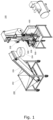
- Figure 1 shows an apparatus 100 for line production of plant growth medium pots or bags.
- the apparatus comprises a storage container 200 with a growth medium feeding tube 208 (partly shown), folding means 300, a suction chamber 400 (shown in a closed position), and a first sealing means 500 (partly, only one of the two welding jaws may be seen).
- the storage container 200 is here shown with two storage chambers, a first storage chamber 202 adapted for holding a large amount of growth medium, and a second storage chamber 204 for holding a relatively smaller amount of growth medium. Growth medium is transported from the first storage chamber 202 to the second storage chamber 204 by a conveyor belt 206.
- the second storage chamber 204 is shown relative to an open-ended dosing chamber 210.
- the open-ended dosing chamber 210 is configured to move between a first position and a second position with the aid of a pneumatic/hydraulic cylinder 212, as indicated by an arrow.
- a first open end 211 of the open-ended dosing chamber 210 connects to the outlet 205 of the second storage chamber 204 in the first position, and wherein the second open end 213 (not shown, but indicated by an arrow) connects to the inlet of the growth medium feeding tube 208 in the second position (here shown in the second position), while the first open end 211 disconnects from outlet 205 of the second storage chamber 204, thereby removing a dosage of growth medium from the second storage chamber 204, through the open-ended dosing chamber 210, and into the growth medium feeding tube 208.
- the storage container 200 further comprises a piston 220 configured to move through the first 211 and second 213 open ends of the open-ended dosing chamber 210 when the open-ended dosing chamber 210 is in the second position.
- This piston is not necessary when producing larger pots or bags.
- a stirrer paddle blade/head 230 is configured as two cylindrical rods extending radially away from the stirrer shaft. This configuration is to avoid demixing of the growth medium.
- FIG. 3 shows an example of how to fold the sheet material into a tubular sheet material.
- the folding means 300 is adapted for continuously folding the free end of a continuous length of water and air permeable sheet material 10 supplied on a reel 20, into a sheet material tube (not shown) around the growth medium feeding tube 208.
- the folding means 300 is here shown comprising two ring- or tube-shaped units.
- the upper tube-shaped unit 310 is a guide means adapted for securing that one side of the sheet material 10 is continuously positioned below the other side of the sheet material 10 in order to position the sides relative to each other for a lap seal to be formed.
- the lower ring-shaped unit 320 is adapted to form the sheet material tube.
- Both units are positioned around the growth medium feeding tube 208 that thereby also aids in the folding operation.
- the free end of the growth medium feeding tube 208 is configured with two slits 209 (only one is shown) extending through its walls. The two slits secure that the part of the sheet material tube that extends beyond/below the free end of the growth medium feeding tube 208 will not collapse during the filling operation. Otherwise, the dosage of growth medium would not be able to be correctly positioned therein.
- FIG. 4 shows the suction chamber 400 relative to the free end of the growth medium feeding tube 208 in accordance with various embodiments of the invention.
- the suction chamber 400 is positioned around and beyond the free end of the growth medium feeding tube 208, and adapted to be in a) an open first configuration (as shown) and b) in a closed second configuration.
- the suction chamber 400 encloses the free end of the growth medium feeding tube 208, and the sheet material tube (not shown) formed around it. Furthermore, it engages and flattens the opposed walls of the water and air permeable sheet material tube at a predefined distance downstream from the free end of the growth medium feeding tube 208; and subsequently removes air out of the chamber (e.g.
- a dosage of growth medium in the dosing chamber 210 and/or in the growth medium feeding tube 208 is transported through the growth medium feeding tube 208 and into the sheet material tube within said suction chamber 400.
- the free end of the growth medium feeding tube 208 is configured with multiple perforations 209 (three are shown) extending through its walls. The perforations secure that the part of the sheet material tube that extends beyond/below the free end of the growth medium feeding tube 208 will not collapse during the filling operation. Otherwise, the dosage of growth medium would not be able to be correctly positioned therein.
- a second sealing means is configured for sealing the sheet material tube along its length, here a lap sealing.
- the lap sealing is made on the sheet material tube when it passes over the growth medium feeding tube.
- the second sealing means comprises a welding jaw 610, and wherein a part of the free end of the growth medium feeding tube comprises a protrusion 620 adapted for receiving said welding jaw 610. Thereby, a part of the free end of the growth medium feeding tube 208 serves as a part of the second sealing means.
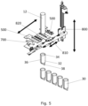
- Figure 5 shows parts of the apparatus for sealing, pulling, and cutting of the tubular sheet material.
- the first sealing means 500 (here configured as two welding jaws) is adapted for forming a sealing in the sheet material tube 12 by engaging and flattening the opposed walls of the open end of the sheet material tube 12 at a position downstream to the suction chamber (not shown). The sealing is performed while the suction chamber is in the closed second configuration.
- the suction chamber moves to its open first configuration, and the continuous length of water and air permeable sheet material is advanced by grabbing and pulling means 800 configured for grabbing the formed sealing in the sheet material tube and pulling the sealing further away from the free end of the growth medium feeding tube (not shown).
- the advantage of grabbing the sealing is to avoid that the sheet material brakes during the pulling operation.
- the grabbing and pulling means 800 is here shown comprising to jaws 810, 820 adapted for grapping the sealing.
- the jaws 810, 820 are shown grabbing the sealing, while the two welding jaws are in a retracted position.
- a cutting means 700 is also shown in a retracted position.
- the cutting means is adapted for separating the formed plant growth pot or bag 30 from the continuous length of water permeable sheet material. The cutting operation is performed subsequently to the pulling operation.
- FIG. 5 An example of a growth medium pot or bag 30 produced by the process of the present invention is also shown in Figure 5 .
- Typical pots or bags prepared by the present invention have a diameter of 20-200 mm, and a height of 20-500 mm.
- the growth medium pot or bag 30 has a closed bottom end and an open top end and comprises a tubular sheet material 32 surrounding a portion of growth medium 34.
- the tubular sheet material is made of a single sheet of water and air permeable sheet material being sealed with two seals formed in said sheet material.
- the first seal is a lap seal 36 joining the two sides of the sheet material to form a tube.
- the second seal 38 (a tap seal) is formed in one of the ends of the tubular sheet material by engaging and flattening the opposed walls of the sheet material tube.
Landscapes
- Life Sciences & Earth Sciences (AREA)
- Environmental Sciences (AREA)
- Engineering & Computer Science (AREA)
- Mechanical Engineering (AREA)
- Cultivation Receptacles Or Flower-Pots, Or Pots For Seedlings (AREA)
- Bag Frames (AREA)
Description
- The present invention relates to the production of growth medium pots or bags.
- Today, most of the greenhouses and nurseries applying hydroponic growth of herbs utilize injection moulded plastic pots. This is very problematic, as there is a dramatic increase of plastic waste in general in the world. Furthermore, when the herbs are harvested, the plastic pots are seldom separated from the root and growth medium, and both parts are therefore not recycled.
- Another present issue is with the downsides of polythene seedling bags for trees and bushes in nurseries. In many countries, after transplanting, the bags are discarded, burned or buried on agricultural land. Bags discarded on farms can enter waterways and cause blockage and may also suffocate aquatic animals. Domestic and wild animals sometimes swallow them, with disastrous effects. The bags also serve as breeding sites for mosquitoes and other disease vectors. Burying the polythene bags in the soil interferes with proper water percolation and aeration of the soil and burning them produces noxious smoke. Hence, there is a need to find an alternative solution.
-
WO2013174386 discloses a method of manufacturing a plant receptacle, wherein the following steps are performed: a) a PLA thread is co-extruded with a flexible aliphatic polyester, said flexible aliphatic polyester comprising 10 wt% to 30 wt% bamboo material, such that the flexible aliphatic polyester covers the PLA thread, thereby creating a weldable biodegradable thread; b) using said weldable biodegradable thread in a woven or non-woven process, making a permeable sheet material; c) continuously forming said sheet material into a continuous receptacle, by bringing the side edges of said sheet material into contact and welding said side edges together; d) cutting said continuous receptacle in predetermined lengths thereby creating separate plant receptacles. Such plant receptacles are not suitable for hydroponic systems as the growth medium will fall out of the pot or bag and into the pot or bag trays of the hydroponic system, thereby obstructing filters and pumps. -
US 3 925 963 A ,WO 92/03914 A1 WO 2017/086038 A1 andUS 2006/285781 A1 illustrate alternative processes for filling a growth medium in a sheet material tube. - It is an object of the present invention to provide an alternative growth medium pot or bag to replace the environmentally unfriendly injection moulded plastic pots or bags. Additionally, it is an object to provide a growth medium pot or bag suitable for hydroponic systems. Furthermore, it is an object to provide machinery for their production.
- A first aspect of the invention is defined by a process for line production of plant growth medium pots or bags with a closed bottom end and an open top end according to claim 1.
- The step ii) is an initiation step that is present to make a closed end in the sheet material tube. The tube will subsequently be closed due to the formation of the second sealing.
- By using a water permeable sheet material, preferably biodegradable, woven or nonwoven, there is no need for the environmentally unfriendly injection moulded plastic pots or bags. Rather, the water permeable sheet material may be recycled together with the plant roots and growth medium in a composting facility. The sheet material must be water permeable in order for the produced plant pot or bag to be able to absorb water and dissolved nutrients. The growth medium pot or bag has a closed bottom end to avoid that growth medium will fall out of the pot or bag and into the pot or bag trays of the hydroponic system, thereby obstructing filters and pumps.
- The term "biodegradable" as used herein describes the chemical dissolution of materials by bacteria or other biological means.
- As used herein, the term "nonwoven sheet material" means a sheet material that has a structure of individual fibers or threads, which are interlaid, but not in an identifiable repeating manner. Nonwoven sheet materials may be formed by a variety of processes such as, for example, meltblowing processes, spunbonding processes, coforming processes, airlaying processes, wetlaying processes, and hydroentangling.
- The fibers used for the water permeable sheet material are preferably biodegradable, which can be natural or synthetic fibers, e.g. cellulosic fibers, protein fibers or synthetic polymer fibers. Natural fibers can comprise pulped or shredded cellulose fibers, such as wood pulp, shredded wood, shredded paper (tissue, newsprint and the like), straw, cotton fiber, composted vegetation, fibrous sphagnum moss, peat moss, shredded stalks including shredded corn stalks and shredded pine straw (including needles, twigs, cones and small branches). Shredded vegetation is preferably dry before shredding. Protein fibers can e.g. be hair or gelatin. Biodegradable synthetic fibers can comprise reconstituted cellulose fibers, such as rayon fibers, vinyl polymer fibers, such as fibrous polyvinyl alcohol, poly lactic acid, and polyamide fibers.
- The term "cellulosic fibers" as used herein describes fibers made from an organic compound derived primarily from plants such as trees.
- The term "wood pulp fibers" as used herein describes a type of cellulosic fiber made from a lignocellulosic fibrous material prepared by chemically or mechanically separating cellulosic fiber from plants such as trees or cotton.
- The term "regenerated/reconstituted cellulosic fibers" as used herein describes a type of cellulosic fiber made from wood pulp using a solvent fiber spinning process. The process involves dissolving wood pulp in a solvent and spinning the resultant spinning solution into fibers.
- In one or more embodiments, the biodegradable and water permeable sheet material consist of spunlaced fibers without fiber binding materials. The term "spunlaced" as used herein refers to a structure of individual fibers or threads, which are physically entangled, without thermal bonding. Physical entanglement may be achieved using a water entanglement process, or alternatively, a needling process or a combination of both processes. The spunlaced fibers provide the strength to the water permeable sheet without the need for a binder, also, and very importantly for the present use, when the water permeable sheet is wet.
- In order for the water permeable sheet material to be sealable, at least some of the fibers should preferably be made from, or coated with, a thermoplastic material. Alternatively, the water permeable sheet material could be coated with a hotmelt composition. Another method for sealing the sheet material tube may be to emboss or sew the sheet parts together.
- In one or more embodiments, the water permeable sheet material is heat sealable.
- In one or more embodiments, step i) comprises sealing the overlapping sheet side parts to one another.
- In one or more embodiments, the water and air permeable sheet material comprises a) fibers coated with a thermoplastic material and/or b) fibers of a thermoplastic material; and wherein the sealings are made by heating.
- In one or more embodiments, the step of continuously folding the free end of a continuous length of water and air permeable sheet material into a sheet material tube comprises sealing the overlapping sheet side parts to one another. Such a sealing is preferable a heat seal extending along the entire length of the sheet material tube. Such a seal may be provided by applying heat to the overlapping sheet side parts that overlay the free end of the growth medium feeding tube.
- The water permeable sheet material must obviously be advanced during the continuous process. Different means may be used, such as a pair of jaws configured to move in the water permeable sheet material advancement direction during their engagement with the sheet material tube. In one or more embodiments, the continuous length of water and air permeable sheet material is advanced by grabbing the first sealing in the sheet material tube and pulling the first sealing further away from the free end of the growth medium feeding tube. The advantage of grabbing the first sealing is to avoid that the sheet material brakes during the pulling operation. Subsequently to separating the first sealing (to bottom in the first plant growth medium pot or bag) from the advancing growth medium feeding tube, the air permeable sheet material is advanced by grabbing the second sealing in the sheet material tube and pulling the second sealing further away from the free end of the growth medium feeding tube.
- The pair of jaws may be welding jaws configured to make the sealings.
- In one or more embodiments, the seals of the sheet material tube are air-cooled prior to the water permeable sheet material advancement operation. This configuration allows for faster production, as the sealings are strengthened rapidly.
- A second aspect relates to an apparatus according to claim 7 for use in the process of the present invention.
- The cutting means may e.g. be a knife, a sharpened blade, or a laser beam.
- In one or more embodiments, the first sealing means is integrated into the bottom part of the suction chamber.
- In one or more embodiments, the sheet material tube is sealed along its length, e.g. by a lap sealing. In one or more embodiments, the apparatus further comprises a second sealing means adapted for heat sealing the overlapping sheet side parts of the sheet material tube to one another. In one or more embodiments, the apparatus further comprises a second sealing means adapted for lap sealing the sheet material tube. The sealing is preferably made on the tube part when it passes over the growth medium feeding tube. Thereby, a part of the free end of the growth medium feeding tube serves as a part of the sealing means. In one or more embodiments, a part of the free end of the growth medium feeding tube comprises a protrusion adapted for receiving a welding jaw.
- In one or more embodiments, the storage container comprises:
- a storage compartment with an outlet in the bottom wall;
- a stirrer configured to maintain the growth medium homogeneous in the storage compartment; and
- an open-ended dosing chamber configured to move between a first position and a second position; wherein its first open end connects to the outlet of the storage compartment in the first position, and wherein its second open end connects to the inlet of the growth medium feeding tube in the second position. When the first open end disconnects from outlet of the storage container, it removes a dosage of growth medium from the storage container, through the open-ended dosing chamber, and into the growth medium feeding tube.
- The storage container with a dosing chamber is a new way of thinking within the field of paper pots, where the growth medium is normally delivered into a cylindrical paper tube as a continuous mass (see e.g.
WO1992003914 ). Such a configuration is not possible, when producing a plant pot or bag according to the present invention. In order to provide space for making the sealings, the growth medium must be provided into the cavity of the continuously formed sheet material tube. Therefore, the growth medium should be delivered in doses. - In one or more embodiments, the open-ended dosing chamber is configured as a block with a channel extending therethrough, and wherein the first open end of the channel connects to the outlet of the storage container in the first position, and wherein the second open end of the channel connects to the inlet of the growth medium feeding tube in the second position. In one or more embodiments, the block is slidingly engaged with the bottom wall of the of the storage container.
- In one or more embodiments, the open-ended dosing chamber is slidingly engaged with bottom wall of the of the storage container.
- In one or more embodiments, the stirrer is configured to change rotation direction each 2-10 dosing operations. This configuration is to avoid demixing of the growth medium.
- In one or more embodiments, the stirrer paddle blade/head is configured as one or more cylindrical rods extending radially away from the stirrer shaft. This configuration is to avoid demixing of the growth medium.
- In one or more embodiments, the apparatus further comprises a piston configured to move through the first and second open ends of the open-ended dosing chamber when the open-ended dosing chamber is in the second position.
- A third aspect which is not according to the appended claims relates to a growth medium pot or bag obtainable by the process according to the present invention.
- A fourth aspect which is not according to the appended claims relates to a growth medium pot or bag with a closed bottom end and an open top end, the growth medium pot or bag comprising a tubular sheet material surrounding a portion of growth medium; wherein the tubular sheet material is made of a single sheet of water and air permeable sheet material being sealed with two seals formed in said sheet material; wherein the first seal is a lap seal joining the two sides of the sheet material to form a tube; and wherein the second seal is formed in one of the ends of the tubular sheet material by engaging and flattening the opposed walls of the sheet material tube.
- In one or more embodiments, the second seal is a tap seal.
- As used in the specification and the appended claims, the singular forms "a", "an", and "the" include plural referents unless the context clearly dictates otherwise. Ranges may be expressed herein as from "about" or "approximately" one particular value and/or to "about" or "approximately" another particular value. When such a range is expressed, another embodiment includes from the one particular value and/or to the other particular value. Similarly, when values are expressed as approximations, by use of the antecedent "about", it will be understood that the particular value forms another embodiment.
- It should be noted that embodiments and features described in the context of one of the aspects of the present invention also apply to the other aspects of the invention.
-
-
Figure 1 shows an apparatus for use in the process in accordance with various embodiments of the invention; -
Figure 2 shows a part of the storage container in accordance with various embodiments of the invention; -
Figure 3 shows an example of how to fold the sheet material into a tubular sheet material; -
Figure 4 shows the suction chamber relative to the free end of the growth medium feeding tube in accordance with various embodiments of the invention; and -
Figure 5 shows parts of the apparatus for sealing, pulling, and cutting of the tubular sheet material. -
Figure 1 shows anapparatus 100 for line production of plant growth medium pots or bags. - The apparatus comprises a
storage container 200 with a growth medium feeding tube 208 (partly shown), folding means 300, a suction chamber 400 (shown in a closed position), and a first sealing means 500 (partly, only one of the two welding jaws may be seen). - The
storage container 200 is here shown with two storage chambers, afirst storage chamber 202 adapted for holding a large amount of growth medium, and asecond storage chamber 204 for holding a relatively smaller amount of growth medium. Growth medium is transported from thefirst storage chamber 202 to thesecond storage chamber 204 by aconveyor belt 206. InFigure 2 , thesecond storage chamber 204 is shown relative to an open-endeddosing chamber 210. The open-endeddosing chamber 210 is configured to move between a first position and a second position with the aid of a pneumatic/hydraulic cylinder 212, as indicated by an arrow. A firstopen end 211 of the open-endeddosing chamber 210 connects to theoutlet 205 of thesecond storage chamber 204 in the first position, and wherein the second open end 213 (not shown, but indicated by an arrow) connects to the inlet of the growthmedium feeding tube 208 in the second position (here shown in the second position), while the firstopen end 211 disconnects fromoutlet 205 of thesecond storage chamber 204, thereby removing a dosage of growth medium from thesecond storage chamber 204, through the open-endeddosing chamber 210, and into the growthmedium feeding tube 208. Thestorage container 200 further comprises apiston 220 configured to move through the first 211 and second 213 open ends of the open-endeddosing chamber 210 when the open-endeddosing chamber 210 is in the second position. This piston is not necessary when producing larger pots or bags. A stirrer paddle blade/head 230 is configured as two cylindrical rods extending radially away from the stirrer shaft. This configuration is to avoid demixing of the growth medium. -
Figure 3 shows an example of how to fold the sheet material into a tubular sheet material. The folding means 300 is adapted for continuously folding the free end of a continuous length of water and airpermeable sheet material 10 supplied on areel 20, into a sheet material tube (not shown) around the growthmedium feeding tube 208. The folding means 300 is here shown comprising two ring- or tube-shaped units. The upper tube-shapedunit 310 is a guide means adapted for securing that one side of thesheet material 10 is continuously positioned below the other side of thesheet material 10 in order to position the sides relative to each other for a lap seal to be formed. The lower ring-shapedunit 320 is adapted to form the sheet material tube. Both units are positioned around the growthmedium feeding tube 208 that thereby also aids in the folding operation. The free end of the growthmedium feeding tube 208 is configured with two slits 209 (only one is shown) extending through its walls. The two slits secure that the part of the sheet material tube that extends beyond/below the free end of the growthmedium feeding tube 208 will not collapse during the filling operation. Otherwise, the dosage of growth medium would not be able to be correctly positioned therein. -
Figure 4 shows thesuction chamber 400 relative to the free end of the growthmedium feeding tube 208 in accordance with various embodiments of the invention. Thesuction chamber 400 is positioned around and beyond the free end of the growthmedium feeding tube 208, and adapted to be in a) an open first configuration (as shown) and b) in a closed second configuration. In the closed second configuration, thesuction chamber 400 encloses the free end of the growthmedium feeding tube 208, and the sheet material tube (not shown) formed around it. Furthermore, it engages and flattens the opposed walls of the water and air permeable sheet material tube at a predefined distance downstream from the free end of the growthmedium feeding tube 208; and subsequently removes air out of the chamber (e.g. by the aid of a pump as seen to the right side inFigure 1 ), such that a dosage of growth medium in thedosing chamber 210 and/or in the growthmedium feeding tube 208, is transported through the growthmedium feeding tube 208 and into the sheet material tube within saidsuction chamber 400. The free end of the growthmedium feeding tube 208 is configured with multiple perforations 209 (three are shown) extending through its walls. The perforations secure that the part of the sheet material tube that extends beyond/below the free end of the growthmedium feeding tube 208 will not collapse during the filling operation. Otherwise, the dosage of growth medium would not be able to be correctly positioned therein. A second sealing means is configured for sealing the sheet material tube along its length, here a lap sealing. The lap sealing is made on the sheet material tube when it passes over the growth medium feeding tube. The second sealing means comprises awelding jaw 610, and wherein a part of the free end of the growth medium feeding tube comprises aprotrusion 620 adapted for receiving saidwelding jaw 610. Thereby, a part of the free end of the growthmedium feeding tube 208 serves as a part of the second sealing means. -
Figure 5 shows parts of the apparatus for sealing, pulling, and cutting of the tubular sheet material. The first sealing means 500 (here configured as two welding jaws) is adapted for forming a sealing in thesheet material tube 12 by engaging and flattening the opposed walls of the open end of thesheet material tube 12 at a position downstream to the suction chamber (not shown). The sealing is performed while the suction chamber is in the closed second configuration. When the two welding jaws retract, the suction chamber moves to its open first configuration, and the continuous length of water and air permeable sheet material is advanced by grabbing and pullingmeans 800 configured for grabbing the formed sealing in the sheet material tube and pulling the sealing further away from the free end of the growth medium feeding tube (not shown). The advantage of grabbing the sealing is to avoid that the sheet material brakes during the pulling operation. The grabbing and pullingmeans 800 is here shown comprising tojaws jaws - A cutting means 700 is also shown in a retracted position. The cutting means is adapted for separating the formed plant growth pot or
bag 30 from the continuous length of water permeable sheet material. The cutting operation is performed subsequently to the pulling operation. - An example of a growth medium pot or
bag 30 produced by the process of the present invention is also shown inFigure 5 . Typical pots or bags prepared by the present invention have a diameter of 20-200 mm, and a height of 20-500 mm. The growth medium pot orbag 30 has a closed bottom end and an open top end and comprises atubular sheet material 32 surrounding a portion ofgrowth medium 34. The tubular sheet material is made of a single sheet of water and air permeable sheet material being sealed with two seals formed in said sheet material. The first seal is alap seal 36 joining the two sides of the sheet material to form a tube. The second seal 38 (a tap seal) is formed in one of the ends of the tubular sheet material by engaging and flattening the opposed walls of the sheet material tube. -
- 10
- Water permeable sheet material
- 12
- Sheet material tube
- 20
- Reel
- 30
- Plant growth pot or bag
- 32
- Tubular sheet material
- 34
- Growth medium
- 36
- Lap seal
- 38
- Seal
- 100
- Apparatus
- 200
- Storage container
- 202
- First storage chamber
- 204
- Second storage chamber
- 205
- Outlet
- 206
- Conveyor belt
- 208
- Growth medium feeding tube
- 209
- Perforation or slit
- 210
- Dosing chamber
- 211
- First open end
- 212
- Pneumatic/hydraulic cylinder
- 213
- Second open end
- 220
- Piston
- 230
- Stirrer paddle blade/head
- 300
- Folding means
- 310
- Upper unit
- 320
- Lower unit
- 400
- Suction chamber
- 500
- First sealing means
- 610
- Welding jaw/second sealing means
- 620
- Protrusion
- 700
- Cutting means
- 800
- Grabbing and pulling means
- 810
- Jaw
- 820
- Jaw
Claims (9)
- A process for line production of plant growth medium pots or bags (30) with a closed bottom end and an open top end, the process comprising the steps of:i) continuously folding the free end of a continuous length of water and air permeable sheet material (10), preferably supplied on a reel (20), into a sheet material tube (12) around and beyond a free end of a growth medium feeding tube (208);ii) forming a first sealing in the sheet material tube (12) by engaging and flattening the opposed walls of the sheet material tube at a position beyond the free end of the growth medium feeding tube (208);wherein the method further comprises the steps of:iii) through the free end of the growth medium feeding tube (208), filling the sheet material tube (12) with a measured amount of growth medium (34);iv) forming a second sealing in the sheet material tube (12) by engaging and flattening the opposed walls of the sheet material tube (12) at a position above the position of the growth medium (34);v) separating the part of the sheet material tube (12) positioned downstream from the second sealing to form a first plant growth medium bag (30) with a closed bottom end and an open top end; and optionallyvi) repeating the steps i), and iii)-v) several times to form a plurality of plant growth medium bags (30) with a closed bottom end and an open top end.
- The process according to claim 1, wherein the continuous length of water and air permeable sheet material (10) is advanced by grabbing the first sealing in the sheet material tube (12) and pulling the first sealing further away from the free end of the growth medium feeding tube (208).
- The process according to claim 2, wherein subsequently to separating the first sealing from the advancing growth medium feeding tube (208), the air permeable sheet material (10) is advanced by grabbing the second sealing in the sheet material tube (12) and pulling the second sealing further away from the free end of the growth medium feeding tube (208).
- The process according to any one of the claims 1-3, wherein step i) comprises sealing the overlapping sheet side parts to one another.
- The process according to any one of the claims 1-4, wherein the water and air permeable sheet material (10) comprises a) fibers coated with a thermoplastic material and/or b) fibers of a thermoplastic material; and wherein the sealings are made by heating.
- The process according to any one of the claims 1-5, wherein the growth medium feeding tube (208) is connected to a growth medium delivering unit comprising:- a storage container (204) adapted for holding growth medium, and with an outlet (205) in the bottom wall;- a stirrer (230) configured to maintain the growth medium homogeneous in the storage container (204); and- an open-ended dosing chamber (210) configured to move between a first position and a second position; wherein the first open end (211) connects to the outlet (205) of the storage container (204) in the first position, and wherein the second open end (213) connects to an inlet of a growth medium feeding tube (208) in the second position, while the first open end (211) disconnects from outlet (205) of the storage container (204), thereby removing a dosage of growth medium from the storage container (204), through the open-ended dosing chamber (210), and into the growth medium feeding tube (208).
- An apparatus (100) for use in the process according to any one of the claims 1-6, the apparatus comprising:- a storage container (200) adapted for holding growth medium, and comprising a growth medium feeding tube (208); wherein the storage container (200) is adapted for delivering dosages of growth medium through its growth medium feeding tube (208);- folding means (300) adapted for continuously folding the free end of a continuous length of water and air permeable sheet material (10), preferably supplied on a reel (20), into a sheet material tube (12) around the growth medium feeding tube (208);- a suction chamber (400) adapted to be positioned around and beyond the free end of the growth medium feeding tube (208), and adapted to be in a) an open first configuration and b) in a closed second configuration; wherein when in the closed second configuration the suction chamber (400) encloses the free end of the growth medium feeding tube (208) and the sheet material tube formed around it, and engages and flattens the opposed walls of the sheet material tube at a predefined distance downstream from the free end of the growth medium feeding tube (208); and subsequently removes air out of the suction chamber (400), such that a dosage of growth medium in the storage container (200) is transported through the growth medium feeding tube (208) and into the sheet material tube within said suction chamber (400);- a first sealing means (500) adapted for forming a first sealing and a second sealing in the sheet material tube by engaging and flattening the opposed walls of the open end of the sheet material tube at a position downstream to the suction chamber (400); wherein the first sealing is formed once during an initiation step prior to the delivery of a first dosage of growth medium to the suction chamber (400), and wherein the second sealing is formed upstream to delivered dosages of growth medium;
wherein the free end of the growth medium feeding tube (208) is configured with one or more perforations or slits (209) extending through its walls; and- cutting means (700) adapted for separating a formed plant growth pot or bag (30) from the continuous length of water permeable sheet material (10) by cutting downstream from said second sealing to form a plant growth pot or bag (30) with an open top end and a closed bottom end. - An apparatus (100) according to claim 7, further comprising a second sealing means (610) adapted for lap sealing the sheet material tube.
- An apparatus (100) according to claim 8, wherein the second sealing means (610) comprises a welding jaw (610), and wherein a part of the free end of the growth medium feeding tube (208) comprises a protrusion (620) adapted for receiving said welding jaw (610).
Applications Claiming Priority (2)
| Application Number | Priority Date | Filing Date | Title |
|---|---|---|---|
| DKPA201800453A DK179996B1 (en) | 2018-08-10 | 2018-08-10 | Process and apparatus for line production of plant growth medium pots or bags |
| PCT/EP2019/070629 WO2020030495A1 (en) | 2018-08-10 | 2019-07-31 | Process and apparatus for line production of plant growth medium pots or bags |
Publications (2)
| Publication Number | Publication Date |
|---|---|
| EP3833178A1 EP3833178A1 (en) | 2021-06-16 |
| EP3833178B1 true EP3833178B1 (en) | 2025-05-07 |
Family
ID=69157097
Family Applications (1)
| Application Number | Title | Priority Date | Filing Date |
|---|---|---|---|
| EP19750097.8A Active EP3833178B1 (en) | 2018-08-10 | 2019-07-31 | Process and apparatus for line production of plant growth medium pots or bags |
Country Status (6)
| Country | Link |
|---|---|
| US (1) | US12129071B2 (en) |
| EP (1) | EP3833178B1 (en) |
| AU (1) | AU2019319541B2 (en) |
| DK (1) | DK179996B1 (en) |
| WO (1) | WO2020030495A1 (en) |
| ZA (1) | ZA202101096B (en) |
Families Citing this family (5)
| Publication number | Priority date | Publication date | Assignee | Title |
|---|---|---|---|---|
| DK181655B1 (en) * | 2020-10-14 | 2024-09-10 | Ellepot As | Hydroponic systems |
| DK181411B1 (en) * | 2021-12-10 | 2023-10-24 | Ellepot As | A process and system for line producing seed filled plant growth medium pots, rods, or bands |
| CN114051802B (en) * | 2021-12-16 | 2022-11-18 | 江西省农业科学院蔬菜花卉研究所 | Sharp point shanxiang circle bagging apparatus for seedling transplantation |
| CN119731085A (en) * | 2022-07-12 | 2025-03-28 | 拉尔斯·彼得·詹森 | Basin filling assembly |
| DK182160B1 (en) * | 2023-10-13 | 2025-09-30 | Ellepot As | Process to produce containers for use in the production of plant growth medium pots and bags, a plant growth medium pot or bag, and an apparatus for use in such a process |
Citations (2)
| Publication number | Priority date | Publication date | Assignee | Title |
|---|---|---|---|---|
| CA2082126A1 (en) * | 1992-11-04 | 1994-05-05 | Allen Monsma | Flexible planter |
| US20060285781A1 (en) * | 2005-05-26 | 2006-12-21 | Zoss Robert A | Easy pour bag |
Family Cites Families (20)
| Publication number | Priority date | Publication date | Assignee | Title |
|---|---|---|---|---|
| US3040490A (en) * | 1960-05-31 | 1962-06-26 | Triangle Package Machinery Co | Apparatus and method for making, filling, and sealing containers |
| SE337957B (en) | 1969-04-01 | 1971-08-23 | Stora Kopparbergs Bergslags Ab | |
| US3807125A (en) * | 1972-07-17 | 1974-04-30 | C Enrich | Apparatus and method for producing seeding containers |
| US3925963A (en) | 1973-04-04 | 1975-12-16 | Dow Chemical Co | Form, fill and seal industrial bag machine |
| FI49469C (en) | 1973-07-16 | 1975-07-10 | Enso Gutzeit Oy | Process for mechanical production of plant cooks. |
| CH595245A5 (en) * | 1976-03-29 | 1978-02-15 | Sig Schweiz Industrieges | |
| US4056132A (en) * | 1976-04-05 | 1977-11-01 | Olinkraft, Inc. | Bag filling apparatus with air contaminate prevention |
| GB1545554A (en) | 1976-08-03 | 1979-05-10 | Nat Res Dev | Growing blocks |
| US4079662A (en) * | 1976-11-30 | 1978-03-21 | Triangle Package Machinery Company | Bag making machine |
| CH667057A5 (en) * | 1985-12-05 | 1988-09-15 | Ipatec Sa | DEVICE FOR VACUUM FILLING OF CONTAINERS AND METHOD FOR ACTIVATING IT. |
| DK211090D0 (en) | 1990-09-03 | 1990-09-03 | Oeyvind Ellegaard | METHOD AND PLANT FOR THE MANUFACTURE OF BLOCK MATERIALS FROM LOST MATERIALS, EX. sphagnum |
| NL1004818C2 (en) | 1996-12-18 | 1998-06-19 | Boomkwekerij Bert Rombouts B V | Method and device for manufacturing substrate plugs compacted from loose material. |
| DE19748805A1 (en) * | 1997-11-05 | 1999-05-06 | Rovema Gmbh | Packaging device |
| JP3667266B2 (en) * | 2000-09-07 | 2005-07-06 | 三島製紙株式会社 | Biodegradable sheet material for molding seedling blocks |
| DK175746B1 (en) | 2002-10-30 | 2005-02-07 | Ellegaard As | Apparatus for compressing growth media pots |
| JP2004267141A (en) * | 2003-03-11 | 2004-09-30 | Toosero Packs Kk | Sheet for seedling-raising container and seedling-raising container |
| US20090236035A1 (en) | 2005-06-29 | 2009-09-24 | Ifa Nurseries, Inc. | Device for protecting container-grown seedling root systems and method for its manufacture |
| PL2852276T3 (en) | 2012-05-22 | 2016-12-30 | Method of manufacturing a plant receptacle as well as a plant receptacle | |
| US10085386B2 (en) | 2013-11-05 | 2018-10-02 | Ellegaard Holdings A/S | Method of manufacturing a plant receptacle as well as a plant receptacle |
| JP6408719B2 (en) | 2015-11-17 | 2018-10-17 | 株式会社イシダ | Bag making and packaging machine |
-
2018
- 2018-08-10 DK DKPA201800453A patent/DK179996B1/en active IP Right Grant
-
2019
- 2019-07-31 US US17/266,757 patent/US12129071B2/en active Active
- 2019-07-31 EP EP19750097.8A patent/EP3833178B1/en active Active
- 2019-07-31 AU AU2019319541A patent/AU2019319541B2/en active Active
- 2019-07-31 WO PCT/EP2019/070629 patent/WO2020030495A1/en not_active Ceased
-
2021
- 2021-02-17 ZA ZA2021/01096A patent/ZA202101096B/en unknown
Patent Citations (2)
| Publication number | Priority date | Publication date | Assignee | Title |
|---|---|---|---|---|
| CA2082126A1 (en) * | 1992-11-04 | 1994-05-05 | Allen Monsma | Flexible planter |
| US20060285781A1 (en) * | 2005-05-26 | 2006-12-21 | Zoss Robert A | Easy pour bag |
Also Published As
| Publication number | Publication date |
|---|---|
| EP3833178A1 (en) | 2021-06-16 |
| DK201800453A1 (en) | 2020-01-14 |
| DK179996B1 (en) | 2020-01-14 |
| AU2019319541A1 (en) | 2021-03-04 |
| ZA202101096B (en) | 2022-09-28 |
| US20210309399A1 (en) | 2021-10-07 |
| WO2020030495A1 (en) | 2020-02-13 |
| AU2019319541B2 (en) | 2024-09-26 |
| US12129071B2 (en) | 2024-10-29 |
Similar Documents
| Publication | Publication Date | Title |
|---|---|---|
| AU2019319541B2 (en) | Process and apparatus for line production of plant growth medium pots or bags | |
| WO2019011742A1 (en) | Process for line production of plant growth medium bags and pots | |
| DK2237656T3 (en) | Irrigation apparatus, method of making this apparatus and means therefor | |
| EP2852276B1 (en) | Method of manufacturing a plant receptacle as well as a plant receptacle | |
| US20260047536A1 (en) | Hydroponic system, and a process for producing a hydroponic system | |
| JP3667266B2 (en) | Biodegradable sheet material for molding seedling blocks | |
| EP2153713A2 (en) | Plant receptacle | |
| DK182160B1 (en) | Process to produce containers for use in the production of plant growth medium pots and bags, a plant growth medium pot or bag, and an apparatus for use in such a process | |
| DK179671B1 (en) | Process for line production of plant growth medium pots | |
| DK180615B1 (en) | A hydroponic system, and a method for producing a hydroponic system | |
| AU2007100624A4 (en) | Plant container | |
| CN203597103U (en) | Tea-oil tree fruit picking machine | |
| WO2016182447A1 (en) | Device and method for collecting slugs | |
| CS232073B1 (en) | Mulching Textiles |
Legal Events
| Date | Code | Title | Description |
|---|---|---|---|
| STAA | Information on the status of an ep patent application or granted ep patent |
Free format text: STATUS: UNKNOWN |
|
| STAA | Information on the status of an ep patent application or granted ep patent |
Free format text: STATUS: THE INTERNATIONAL PUBLICATION HAS BEEN MADE |
|
| PUAI | Public reference made under article 153(3) epc to a published international application that has entered the european phase |
Free format text: ORIGINAL CODE: 0009012 |
|
| STAA | Information on the status of an ep patent application or granted ep patent |
Free format text: STATUS: REQUEST FOR EXAMINATION WAS MADE |
|
| 17P | Request for examination filed |
Effective date: 20210310 |
|
| AK | Designated contracting states |
Kind code of ref document: A1 Designated state(s): AL AT BE BG CH CY CZ DE DK EE ES FI FR GB GR HR HU IE IS IT LI LT LU LV MC MK MT NL NO PL PT RO RS SE SI SK SM TR |
|
| DAV | Request for validation of the european patent (deleted) | ||
| DAX | Request for extension of the european patent (deleted) | ||
| STAA | Information on the status of an ep patent application or granted ep patent |
Free format text: STATUS: EXAMINATION IS IN PROGRESS |
|
| 17Q | First examination report despatched |
Effective date: 20230616 |
|
| GRAP | Despatch of communication of intention to grant a patent |
Free format text: ORIGINAL CODE: EPIDOSNIGR1 |
|
| STAA | Information on the status of an ep patent application or granted ep patent |
Free format text: STATUS: GRANT OF PATENT IS INTENDED |
|
| RIC1 | Information provided on ipc code assigned before grant |
Ipc: B65B 51/30 20060101ALN20241121BHEP Ipc: B65B 37/00 20060101ALI20241121BHEP Ipc: B65B 9/20 20120101ALI20241121BHEP Ipc: A01G 24/60 20180101ALI20241121BHEP Ipc: A01G 24/50 20180101ALI20241121BHEP Ipc: A01G 9/08 20060101AFI20241121BHEP |
|
| INTG | Intention to grant announced |
Effective date: 20241129 |
|
| GRAS | Grant fee paid |
Free format text: ORIGINAL CODE: EPIDOSNIGR3 |
|
| GRAA | (expected) grant |
Free format text: ORIGINAL CODE: 0009210 |
|
| STAA | Information on the status of an ep patent application or granted ep patent |
Free format text: STATUS: THE PATENT HAS BEEN GRANTED |
|
| AK | Designated contracting states |
Kind code of ref document: B1 Designated state(s): AL AT BE BG CH CY CZ DE DK EE ES FI FR GB GR HR HU IE IS IT LI LT LU LV MC MK MT NL NO PL PT RO RS SE SI SK SM TR |
|
| REG | Reference to a national code |
Ref country code: GB Ref legal event code: FG4D |
|
| REG | Reference to a national code |
Ref country code: CH Ref legal event code: EP |
|
| REG | Reference to a national code |
Ref country code: DE Ref legal event code: R096 Ref document number: 602019069636 Country of ref document: DE |
|
| REG | Reference to a national code |
Ref country code: IE Ref legal event code: FG4D |
|
| REG | Reference to a national code |
Ref country code: NL Ref legal event code: FP |
|
| REG | Reference to a national code |
Ref country code: SE Ref legal event code: TRGR |
|
| PGFP | Annual fee paid to national office [announced via postgrant information from national office to epo] |
Ref country code: NL Payment date: 20250726 Year of fee payment: 7 |
|
| PG25 | Lapsed in a contracting state [announced via postgrant information from national office to epo] |
Ref country code: FI Free format text: LAPSE BECAUSE OF FAILURE TO SUBMIT A TRANSLATION OF THE DESCRIPTION OR TO PAY THE FEE WITHIN THE PRESCRIBED TIME-LIMIT Effective date: 20250507 Ref country code: PT Free format text: LAPSE BECAUSE OF FAILURE TO SUBMIT A TRANSLATION OF THE DESCRIPTION OR TO PAY THE FEE WITHIN THE PRESCRIBED TIME-LIMIT Effective date: 20250908 Ref country code: ES Free format text: LAPSE BECAUSE OF FAILURE TO SUBMIT A TRANSLATION OF THE DESCRIPTION OR TO PAY THE FEE WITHIN THE PRESCRIBED TIME-LIMIT Effective date: 20250507 |
|
| PGFP | Annual fee paid to national office [announced via postgrant information from national office to epo] |
Ref country code: DE Payment date: 20250729 Year of fee payment: 7 |
|
| REG | Reference to a national code |
Ref country code: LT Ref legal event code: MG9D |
|
| PG25 | Lapsed in a contracting state [announced via postgrant information from national office to epo] |
Ref country code: NO Free format text: LAPSE BECAUSE OF FAILURE TO SUBMIT A TRANSLATION OF THE DESCRIPTION OR TO PAY THE FEE WITHIN THE PRESCRIBED TIME-LIMIT Effective date: 20250807 Ref country code: GR Free format text: LAPSE BECAUSE OF FAILURE TO SUBMIT A TRANSLATION OF THE DESCRIPTION OR TO PAY THE FEE WITHIN THE PRESCRIBED TIME-LIMIT Effective date: 20250808 |
|
| PG25 | Lapsed in a contracting state [announced via postgrant information from national office to epo] |
Ref country code: PL Free format text: LAPSE BECAUSE OF FAILURE TO SUBMIT A TRANSLATION OF THE DESCRIPTION OR TO PAY THE FEE WITHIN THE PRESCRIBED TIME-LIMIT Effective date: 20250507 |
|
| REG | Reference to a national code |
Ref country code: AT Ref legal event code: MK05 Ref document number: 1791378 Country of ref document: AT Kind code of ref document: T Effective date: 20250507 |
|
| PG25 | Lapsed in a contracting state [announced via postgrant information from national office to epo] |
Ref country code: BG Free format text: LAPSE BECAUSE OF FAILURE TO SUBMIT A TRANSLATION OF THE DESCRIPTION OR TO PAY THE FEE WITHIN THE PRESCRIBED TIME-LIMIT Effective date: 20250507 |
|
| PG25 | Lapsed in a contracting state [announced via postgrant information from national office to epo] |
Ref country code: HR Free format text: LAPSE BECAUSE OF FAILURE TO SUBMIT A TRANSLATION OF THE DESCRIPTION OR TO PAY THE FEE WITHIN THE PRESCRIBED TIME-LIMIT Effective date: 20250507 |
|
| PG25 | Lapsed in a contracting state [announced via postgrant information from national office to epo] |
Ref country code: AT Free format text: LAPSE BECAUSE OF FAILURE TO SUBMIT A TRANSLATION OF THE DESCRIPTION OR TO PAY THE FEE WITHIN THE PRESCRIBED TIME-LIMIT Effective date: 20250507 |
|
| PGFP | Annual fee paid to national office [announced via postgrant information from national office to epo] |
Ref country code: SE Payment date: 20250727 Year of fee payment: 7 |
|
| PG25 | Lapsed in a contracting state [announced via postgrant information from national office to epo] |
Ref country code: RS Free format text: LAPSE BECAUSE OF FAILURE TO SUBMIT A TRANSLATION OF THE DESCRIPTION OR TO PAY THE FEE WITHIN THE PRESCRIBED TIME-LIMIT Effective date: 20250807 |
|
| PG25 | Lapsed in a contracting state [announced via postgrant information from national office to epo] |
Ref country code: IS Free format text: LAPSE BECAUSE OF FAILURE TO SUBMIT A TRANSLATION OF THE DESCRIPTION OR TO PAY THE FEE WITHIN THE PRESCRIBED TIME-LIMIT Effective date: 20250907 |
|
| PG25 | Lapsed in a contracting state [announced via postgrant information from national office to epo] |
Ref country code: LV Free format text: LAPSE BECAUSE OF FAILURE TO SUBMIT A TRANSLATION OF THE DESCRIPTION OR TO PAY THE FEE WITHIN THE PRESCRIBED TIME-LIMIT Effective date: 20250507 |
|
| PG25 | Lapsed in a contracting state [announced via postgrant information from national office to epo] |
Ref country code: DK Free format text: LAPSE BECAUSE OF FAILURE TO SUBMIT A TRANSLATION OF THE DESCRIPTION OR TO PAY THE FEE WITHIN THE PRESCRIBED TIME-LIMIT Effective date: 20250507 Ref country code: SM Free format text: LAPSE BECAUSE OF FAILURE TO SUBMIT A TRANSLATION OF THE DESCRIPTION OR TO PAY THE FEE WITHIN THE PRESCRIBED TIME-LIMIT Effective date: 20250507 |
|
| PG25 | Lapsed in a contracting state [announced via postgrant information from national office to epo] |
Ref country code: CZ Free format text: LAPSE BECAUSE OF FAILURE TO SUBMIT A TRANSLATION OF THE DESCRIPTION OR TO PAY THE FEE WITHIN THE PRESCRIBED TIME-LIMIT Effective date: 20250507 |
|
| PG25 | Lapsed in a contracting state [announced via postgrant information from national office to epo] |
Ref country code: EE Free format text: LAPSE BECAUSE OF FAILURE TO SUBMIT A TRANSLATION OF THE DESCRIPTION OR TO PAY THE FEE WITHIN THE PRESCRIBED TIME-LIMIT Effective date: 20250507 |
|
| PG25 | Lapsed in a contracting state [announced via postgrant information from national office to epo] |
Ref country code: SK Free format text: LAPSE BECAUSE OF FAILURE TO SUBMIT A TRANSLATION OF THE DESCRIPTION OR TO PAY THE FEE WITHIN THE PRESCRIBED TIME-LIMIT Effective date: 20250507 Ref country code: RO Free format text: LAPSE BECAUSE OF FAILURE TO SUBMIT A TRANSLATION OF THE DESCRIPTION OR TO PAY THE FEE WITHIN THE PRESCRIBED TIME-LIMIT Effective date: 20250507 |
|
| PG25 | Lapsed in a contracting state [announced via postgrant information from national office to epo] |
Ref country code: IT Free format text: LAPSE BECAUSE OF FAILURE TO SUBMIT A TRANSLATION OF THE DESCRIPTION OR TO PAY THE FEE WITHIN THE PRESCRIBED TIME-LIMIT Effective date: 20250507 |
|
| REG | Reference to a national code |
Ref country code: DE Ref legal event code: R097 Ref document number: 602019069636 Country of ref document: DE |
|
| REG | Reference to a national code |
Ref country code: CH Ref legal event code: H13 Free format text: ST27 STATUS EVENT CODE: U-0-0-H10-H13 (AS PROVIDED BY THE NATIONAL OFFICE) Effective date: 20260224 |
|
| PLBE | No opposition filed within time limit |
Free format text: ORIGINAL CODE: 0009261 |
|
| STAA | Information on the status of an ep patent application or granted ep patent |
Free format text: STATUS: NO OPPOSITION FILED WITHIN TIME LIMIT |
|
| PG25 | Lapsed in a contracting state [announced via postgrant information from national office to epo] |
Ref country code: LU Free format text: LAPSE BECAUSE OF NON-PAYMENT OF DUE FEES Effective date: 20250731 |
|
| REG | Reference to a national code |
Ref country code: CH Ref legal event code: L10 Free format text: ST27 STATUS EVENT CODE: U-0-0-L10-L00 (AS PROVIDED BY THE NATIONAL OFFICE) Effective date: 20260318 |
|
| REG | Reference to a national code |
Ref country code: BE Ref legal event code: MM Effective date: 20250731 |
|
| 26N | No opposition filed |
Effective date: 20260210 |
|
| PG25 | Lapsed in a contracting state [announced via postgrant information from national office to epo] |
Ref country code: BE Free format text: LAPSE BECAUSE OF NON-PAYMENT OF DUE FEES Effective date: 20250731 |
|
| PG25 | Lapsed in a contracting state [announced via postgrant information from national office to epo] |
Ref country code: FR Free format text: LAPSE BECAUSE OF NON-PAYMENT OF DUE FEES Effective date: 20250731 |
|
| PG25 | Lapsed in a contracting state [announced via postgrant information from national office to epo] |
Ref country code: CH Free format text: LAPSE BECAUSE OF NON-PAYMENT OF DUE FEES Effective date: 20250731 |
|
| GBPC | Gb: european patent ceased through non-payment of renewal fee |
Effective date: 20250807 |
|
| PG25 | Lapsed in a contracting state [announced via postgrant information from national office to epo] |
Ref country code: LT Free format text: LAPSE BECAUSE OF FAILURE TO SUBMIT A TRANSLATION OF THE DESCRIPTION OR TO PAY THE FEE WITHIN THE PRESCRIBED TIME-LIMIT Effective date: 20250507 |
|
| PG25 | Lapsed in a contracting state [announced via postgrant information from national office to epo] |
Ref country code: GB Free format text: LAPSE BECAUSE OF NON-PAYMENT OF DUE FEES Effective date: 20250807 |
|
| PG25 | Lapsed in a contracting state [announced via postgrant information from national office to epo] |
Ref country code: IE Free format text: LAPSE BECAUSE OF NON-PAYMENT OF DUE FEES Effective date: 20250731 |
|
| PG25 | Lapsed in a contracting state [announced via postgrant information from national office to epo] |
Ref country code: MC Free format text: LAPSE BECAUSE OF FAILURE TO SUBMIT A TRANSLATION OF THE DESCRIPTION OR TO PAY THE FEE WITHIN THE PRESCRIBED TIME-LIMIT Effective date: 20250507 |
|
| PG25 | Lapsed in a contracting state [announced via postgrant information from national office to epo] |
Ref country code: CY Free format text: LAPSE BECAUSE OF FAILURE TO SUBMIT A TRANSLATION OF THE DESCRIPTION OR TO PAY THE FEE WITHIN THE PRESCRIBED TIME-LIMIT Effective date: 20250507 |