EP3833168A1 - Slide rail assembly and bracket device thereof - Google Patents
Slide rail assembly and bracket device thereof Download PDFInfo
- Publication number
- EP3833168A1 EP3833168A1 EP20169820.6A EP20169820A EP3833168A1 EP 3833168 A1 EP3833168 A1 EP 3833168A1 EP 20169820 A EP20169820 A EP 20169820A EP 3833168 A1 EP3833168 A1 EP 3833168A1
- Authority
- EP
- European Patent Office
- Prior art keywords
- bracket device
- mounting member
- slide rail
- rail assembly
- post
- Prior art date
- Legal status (The legal status is an assumption and is not a legal conclusion. Google has not performed a legal analysis and makes no representation as to the accuracy of the status listed.)
- Granted
Links
Images




Classifications
-
- A—HUMAN NECESSITIES
- A47—FURNITURE; DOMESTIC ARTICLES OR APPLIANCES; COFFEE MILLS; SPICE MILLS; SUCTION CLEANERS IN GENERAL
- A47B—TABLES; DESKS; OFFICE FURNITURE; CABINETS; DRAWERS; GENERAL DETAILS OF FURNITURE
- A47B88/00—Drawers for tables, cabinets or like furniture; Guides for drawers
- A47B88/40—Sliding drawers; Slides or guides therefor
- A47B88/423—Fastening devices for slides or guides
- A47B88/43—Fastening devices for slides or guides at cabinet side
-
- A—HUMAN NECESSITIES
- A47—FURNITURE; DOMESTIC ARTICLES OR APPLIANCES; COFFEE MILLS; SPICE MILLS; SUCTION CLEANERS IN GENERAL
- A47B—TABLES; DESKS; OFFICE FURNITURE; CABINETS; DRAWERS; GENERAL DETAILS OF FURNITURE
- A47B96/00—Details of cabinets, racks or shelf units not covered by a single one of groups A47B43/00 - A47B95/00; General details of furniture
- A47B96/06—Brackets or similar supporting means for cabinets, racks or shelves
- A47B96/07—Brackets or similar supporting means for cabinets, racks or shelves adjustable in themselves
-
- H—ELECTRICITY
- H05—ELECTRIC TECHNIQUES NOT OTHERWISE PROVIDED FOR
- H05K—PRINTED CIRCUITS; CASINGS OR CONSTRUCTIONAL DETAILS OF ELECTRIC APPARATUS; MANUFACTURE OF ASSEMBLAGES OF ELECTRICAL COMPONENTS
- H05K7/00—Constructional details common to different types of electric apparatus
- H05K7/14—Mounting supporting structure in casing or on frame or rack
- H05K7/1485—Servers; Data center rooms, e.g. 19-inch computer racks
- H05K7/1488—Cabinets therefor, e.g. chassis or racks or mechanical interfaces between blades and support structures
- H05K7/1489—Cabinets therefor, e.g. chassis or racks or mechanical interfaces between blades and support structures characterized by the mounting of blades therein, e.g. brackets, rails, trays
-
- H—ELECTRICITY
- H05—ELECTRIC TECHNIQUES NOT OTHERWISE PROVIDED FOR
- H05K—PRINTED CIRCUITS; CASINGS OR CONSTRUCTIONAL DETAILS OF ELECTRIC APPARATUS; MANUFACTURE OF ASSEMBLAGES OF ELECTRICAL COMPONENTS
- H05K7/00—Constructional details common to different types of electric apparatus
- H05K7/18—Construction of rack or frame
- H05K7/183—Construction of rack or frame support rails therefor
Definitions
- the present invention relates to a bracket device applicable to a slide rail assembly.
- a bracket device is applicable to a slide rail assembly, such that the slide rail assembly can be mounted to a post of a rack through the bracket device.
- US patent number US 9,930,805 B2 discloses a bracket and a foolproof device thereof.
- the foolproof device comprises a sliding block and a positioning member. As shown in FIG. 4 and FIG. 5 of the patent, when a mounting base of the bracket is rotated 180 degrees, the positioning member falls into an engagement feature of the sliding block due to gravity, such that the sliding block is not movable relative to the mounting base. When the bracket is placed at a first mounting angle relative to a post, the bracket is not interfered by the foolproof device and is able to be mounted to a rack.
- the sliding block of the foolproof device When the bracket is placed at a second mounting angle relative to the post, the sliding block of the foolproof device is not movable relative to the mounting base, such that the bracket is blocked by the foolproof device to be prevented from being mounted to the rack.
- the sliding block of the patent is not configured to be mounted to a mounting hole of the post.
- US patent number US 9,801,467 B2 discloses a bracket device including a bracket, at least one mounting member, a locking member, and a fool-proofing member.
- the at least one mounting member is mounted on the bracket.
- the locking member is movable with respect to the bracket.
- the fool-proofing member is located at a first position or a second position with respect to the bracket. When the bracket is at a first mounting angle, the fool-proofing member is located at the first position and is unable to block the locking member from moving with respect to the bracket.
- the fool-proofing member is displaced from the first position to the second position and ends up blocking the moving path of the locking member with respect to the bracket.
- a foolproof function cannot be achieved without the locking member.
- the present invention aims at providing a bracket device of a slide rail assembly with a foolproof function.
- the claimed bracket device comprises a longitudinal wall and a mounting member.
- the mounting member is movable relative to the longitudinal wall along a height direction of the longitudinal wall to be located at one of a first position and a second position.
- the bracket device is rotated a predetermined angle to be switched from a first state to a second state, the mounting member is configured to be moved from the first position to the second position.
- the claimed slide rail assembly comprises a rail member.
- the rail member has a first end part, a second end part and a longitudinal body arranged between the first end part and the second end part.
- the rail member is arranged with a first bracket device and a second bracket device respectively adjacent to the first end part and the second end part.
- the first bracket device comprises a longitudinal wall and a mounting member.
- the mounting member is movable relative to the longitudinal wall along a height direction of the longitudinal wall to be located at one of a first position and a second position.
- a slide rail assembly 20 comprises a rail member 22 according to an embodiment of the present invention.
- the slide rail assembly 20 further comprises a movable rail 23 retractably connected to the rail member 22 and longitudinally movable relative to the rail member 22.
- the rail member 22 has a first end part 24a, a second end part 24b and a longitudinal body 26 arranged between the first end part 24a and the second end part 24b.
- the rail member 22 is arranged with a first bracket device 28 adjacent to the first end part 24a, and a second bracket device 30 adjacent to the second end part 24b.
- the rail member 22 is arranged with a reinforcing member 34 configured to enhance structural strength of the rail member 22, and the second bracket device 30 is connected to the rail member 22 and adjacent to the reinforcing member 34.
- the first bracket device 28 is connected to the rail member 22.
- the first bracket device 28 comprises a longitudinal wall 36 and a mounting member 38.
- the longitudinal wall 36 is configured to be connected to the rail member 22 through fixing features 39.
- the first bracket device 28 further comprises an extension wall 40 connected to the longitudinal wall 36.
- the extension wall 40 is substantially perpendicularly connected to the longitudinal wall 36, but the present invention is not limited thereto.
- the mounting member 38 is movable relative to the longitudinal wall 36 along a height direction H of the longitudinal wall 36.
- the height direction H is substantially perpendicular to a longitudinal direction L of the longitudinal wall 36 (or a longitudinal direction of the rail member 22).
- the mounting member 38 is movable relative to the longitudinal wall 36 along the height direction H through the extension wall 40.
- the extension wall 40 comprises a first part 42 and a second part 44.
- a path 46 is defined between the first part 42 and the second part 44, and the path 46 is arranged along the height direction H.
- the path 46 is an elongated hole, but the present invention is not limited thereto.
- the mounting member 38 is configured to pass through a portion of the elongated hole.
- the mounting member 38 comprises a first feature 48 and a second feature 50 (please also refer to FIG. 3 ) respectively located at a front side and a rear side of the extension wall 40.
- Both transverse dimensions of the first feature 48 and the second feature 50 of the mounting member 38 are greater than a transverse dimension of the path 46 of the extension wall 40, in order to prevent the mounting member 38 from being moved relative to the extension wall 40 along the longitudinal direction L (such as forward or backward).
- the mounting member 38 has an extension section 52 extended from the second feature 50, and the extension section 52 has a mounting structure 54 (as shown in FIG. 3 ) .
- the mounting structure 54 can be a groove, but the present invention is not limited thereto.
- the first feature 48 can be a fastening ring, but the present invention is not limited thereto.
- the fastening ring is configured to engage with the mounting structure 54.
- a middle part 56 is located between the first feature 48 and the second feature 50.
- the middle part 56 of the mounting member 38 passes through a portion of the path 46 (such as the elongated hole) of the extension wall 40 to be located a corresponding position between the first part 42 and the second part 44.
- the first bracket device 28 further comprises at least one connecting member 58 fixed relative to the longitudinal wall 36.
- the extension wall 40 of the first bracket device 28 is arranged with a plurality of connecting members 58, and the plurality of the connecting members 58 and the mounting member 38 are arranged on the extension wall 40 along the height direction H.
- the second bracket device 30 comprises at least one connecting feature 60.
- the second bracket device 30 comprises a plurality of connecting features 60, and the plurality of connecting features 60 are arranged on the second bracket device 30 along the height direction H.
- the mounting member 38 is configured to be moved from a first position P1 (as shown in FIG. 1 ) to a second position P2 (as shown in FIG. 4 ) .
- the mounting member 38 can be moved from the first position P1 to the second position P2 by gravity.
- the predetermined angle R is substantially 180 degrees. (That is, the slide rail assembly 20 in the first state shown in FIG. 1 is flipped upside-down to become the slide rail assembly 20 in the second state shown in FIG. 4 .)
- the slide rail assembly 20 is applicable to a first post 62 and a second post 64 of a rack.
- the first post 62 has a plurality of mounting holes 66 arranged along the height direction H.
- the second post 64 has a plurality of connecting holes 68 arranged along the height direction H.
- the rack can be a cabinet complying with a specification defined by the Electronic Industries Association (EIA) or the Open Compute Project (OCP).
- EIA Electronic Industries Association
- OCP Open Compute Project
- the mounting member 38 of the first bracket device 28 is located at the first position P1 and configured to be mounted to one of the mounting holes 66 of the first post 62, and the connecting member 58 of the first bracket device 28 is configured to be mounted to another mounting hole 66 of the first post 62.
- the connecting feature 60 of the second bracket device 30 is configured to be mounted to the connecting hole 68 of the second post 64.
- the cabinet can comply with the specification defined by the Electronic Industries Association (EIA) or the Open Compute Project (OCP) .
- EIA Electronic Industries Association
- OCP Open Compute Project
- the cabinet complies with the specification defined by EIA.
- Each three mounting holes among the plurality of mounting holes of the first post 62 are defined as a rack unit, that is, 1U. (Two rack units are called 2U, and so on.)
- a first standard spacing is defined between two adjacent mounting holes in each rack unit, and a second standard spacing is defined between each two adjacent rack units.
- a first rack unit comprises a first mounting hole 66a, a second mounting hole 66b and a third mounting hole 66c; and a second rack unit comprises a fourth mounting hole 66d, a fifth mounting hole 66e and a sixth mounting hole 66f.
- the first standard spacing is defined between the first mounting hole 66a and the second mounting hole 66b (and between the second mounting hole 66b and the third mounting hole 66c).
- the second standard spacing is defined between the third mounting hole 66c and the fourth mounting hole 66d.
- the mounting member 38 of the first bracket device 28 is located at the first position P1 to be aligned with the first mounting hole 66a of the first post 62 for mounting into the first mounting hole 66a, and the connecting member 58 of the first bracket device 28 is configured to be mounted to the second mounting hole 66b of the first post 62.
- the mounting member 38 is located at the first position P1, and the mounting member 38 can be supported by the second part 44 in the path 46 through the middle part 56 (as shown in FIG. 6 ).
- the mounting member 38 of the first bracket device 28 is located at the second position P2 and prevented from being mounted to the first mounting hole 66a of the first post 62.
- the mounting member 38 of the first bracket device 28 is located at the second position P2
- the mounting member 38 is not aligned with the first mounting hole 66a of the first post 62
- the mounting member 38 is configured to contact (such as abut against) a wall surface W of the first post 62 (that is, the mounting member 38 contacts the wall surface W on the first standard spacing between two adjacent mounting holes of the first post 62) to cause interference.
- a gap G (as shown in FIG.
- the mounting member 38 cannot be mounted to the first mounting hole 66a of the first post 62.
- the connecting member 58 of the first bracket device 28 cannot be mounted to the second mounting hole 66b of the first post 62.
- a plurality of holes specified by the EIA or OCP can only allow the plurality of connecting members arranged at predetermined intervals to insert therein. Once the interval between each two adjacent connecting members does not match the spacing between two adjacent holes specified by EIA or OCP, the plurality of connecting members on the bracket cannot be mounted to the holes specified by EIC or OCP.
- the first bracket device 28 of the slide rail assembly 20 is characterized in that:
Landscapes
- Engineering & Computer Science (AREA)
- Microelectronics & Electronic Packaging (AREA)
- Computer Hardware Design (AREA)
- General Engineering & Computer Science (AREA)
- Drawers Of Furniture (AREA)
Abstract
Description
- The present invention relates to a bracket device applicable to a slide rail assembly.
- Generally, a bracket device is applicable to a slide rail assembly, such that the slide rail assembly can be mounted to a post of a rack through the bracket device.
- US patent number
US 9,930,805 B2 FIG. 4 andFIG. 5 of the patent, when a mounting base of the bracket is rotated 180 degrees, the positioning member falls into an engagement feature of the sliding block due to gravity, such that the sliding block is not movable relative to the mounting base. When the bracket is placed at a first mounting angle relative to a post, the bracket is not interfered by the foolproof device and is able to be mounted to a rack. When the bracket is placed at a second mounting angle relative to the post, the sliding block of the foolproof device is not movable relative to the mounting base, such that the bracket is blocked by the foolproof device to be prevented from being mounted to the rack. However, the sliding block of the patent is not configured to be mounted to a mounting hole of the post. - US patent number
US 9,801,467 B2 - Therefore, for different market requirements, it is important to develop various products with a foolproof function.
- This in mind, the present invention aims at providing a bracket device of a slide rail assembly with a foolproof function.
- This is achieved by a bracket device according to claim 1, and a slide rail assembly according to claim 8. The dependent claims pertain to corresponding further developments and improvements.
- As will be seen more clearly from the detailed description following below, the claimed bracket device comprises a longitudinal wall and a mounting member. The mounting member is movable relative to the longitudinal wall along a height direction of the longitudinal wall to be located at one of a first position and a second position. When the bracket device is rotated a predetermined angle to be switched from a first state to a second state, the mounting member is configured to be moved from the first position to the second position.
- As will be seen more clearly from the detailed description following below, the claimed slide rail assembly comprises a rail member. The rail member has a first end part, a second end part and a longitudinal body arranged between the first end part and the second end part. The rail member is arranged with a first bracket device and a second bracket device respectively adjacent to the first end part and the second end part. The first bracket device comprises a longitudinal wall and a mounting member. The mounting member is movable relative to the longitudinal wall along a height direction of the longitudinal wall to be located at one of a first position and a second position.
- In the following, the invention is further illustrated by way of example, taking reference to the accompanying drawings thereof:
-
FIG. 1 is a diagram showing a slide rail assembly being in a first state according to an embodiment of the present invention; -
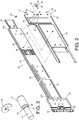
FIG. 2 is an exploded view of the slide rail assembly and a first bracket device according to an embodiment of the present invention; -
FIG. 3 is an exploded view of a mounting member of the first bracket device according to an embodiment of the present invention; -
FIG. 4 is a diagram showing the slide rail assembly being in a second state according to an embodiment of the present invention; -
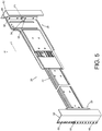
FIG. 5 is a diagram showing the slide rail assembly in the first state being configured to be mounted to a rack according to an embodiment of the present invention; -
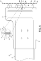
FIG. 6 is a diagram showing the slide rail assembly in the first state before being mounted to a post of the rack according to an embodiment of the present invention; -
FIG. 7 is a diagram showing the slide rail assembly in the first state after being mounted to the post of the rack according to an embodiment of the present invention; -
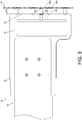
FIG. 8 is a diagram showing the slide rail assembly in the second state and unable to be mounted to the post of the rack according to an embodiment of the present invention; and -
FIG. 9 is a diagram showing the slide rail assembly in the second state being prevented from being mounted to the post of the rack according to an embodiment of the present invention. - As shown in
FIG. 1 andFIG. 2 , aslide rail assembly 20 comprises arail member 22 according to an embodiment of the present invention. Preferably, theslide rail assembly 20 further comprises amovable rail 23 retractably connected to therail member 22 and longitudinally movable relative to therail member 22. Therail member 22 has afirst end part 24a, asecond end part 24b and alongitudinal body 26 arranged between thefirst end part 24a and thesecond end part 24b. Therail member 22 is arranged with afirst bracket device 28 adjacent to thefirst end part 24a, and asecond bracket device 30 adjacent to thesecond end part 24b. - Preferably, the
rail member 22 is arranged with a reinforcingmember 34 configured to enhance structural strength of therail member 22, and thesecond bracket device 30 is connected to therail member 22 and adjacent to the reinforcingmember 34. On the other hand, thefirst bracket device 28 is connected to therail member 22. Thefirst bracket device 28 comprises alongitudinal wall 36 and amounting member 38. Thelongitudinal wall 36 is configured to be connected to therail member 22 throughfixing features 39. In addition, thefirst bracket device 28 further comprises anextension wall 40 connected to thelongitudinal wall 36. In the present embodiment, theextension wall 40 is substantially perpendicularly connected to thelongitudinal wall 36, but the present invention is not limited thereto. - The
mounting member 38 is movable relative to thelongitudinal wall 36 along a height direction H of thelongitudinal wall 36. The height direction H is substantially perpendicular to a longitudinal direction L of the longitudinal wall 36 (or a longitudinal direction of the rail member 22). - Preferably, the
mounting member 38 is movable relative to thelongitudinal wall 36 along the height direction H through theextension wall 40. Moreover, theextension wall 40 comprises afirst part 42 and asecond part 44. Apath 46 is defined between thefirst part 42 and thesecond part 44, and thepath 46 is arranged along the height direction H. In the present embodiment, thepath 46 is an elongated hole, but the present invention is not limited thereto. Themounting member 38 is configured to pass through a portion of the elongated hole. Themounting member 38 comprises afirst feature 48 and a second feature 50 (please also refer toFIG. 3 ) respectively located at a front side and a rear side of theextension wall 40. Both transverse dimensions of thefirst feature 48 and thesecond feature 50 of themounting member 38 are greater than a transverse dimension of thepath 46 of theextension wall 40, in order to prevent themounting member 38 from being moved relative to theextension wall 40 along the longitudinal direction L (such as forward or backward). - Preferably, the
mounting member 38 has anextension section 52 extended from thesecond feature 50, and theextension section 52 has a mounting structure 54 (as shown inFIG. 3 ) . Themounting structure 54 can be a groove, but the present invention is not limited thereto. Thefirst feature 48 can be a fastening ring, but the present invention is not limited thereto. The fastening ring is configured to engage with themounting structure 54. Amiddle part 56 is located between thefirst feature 48 and thesecond feature 50. Themiddle part 56 of the mountingmember 38 passes through a portion of the path 46 (such as the elongated hole) of theextension wall 40 to be located a corresponding position between thefirst part 42 and thesecond part 44. - Preferably, the
first bracket device 28 further comprises at least one connectingmember 58 fixed relative to thelongitudinal wall 36. In the present embodiment, theextension wall 40 of thefirst bracket device 28 is arranged with a plurality of connectingmembers 58, and the plurality of the connectingmembers 58 and the mountingmember 38 are arranged on theextension wall 40 along the height direction H. On the other hand, thesecond bracket device 30 comprises at least one connectingfeature 60. In the present embodiment, thesecond bracket device 30 comprises a plurality of connectingfeatures 60, and the plurality of connectingfeatures 60 are arranged on thesecond bracket device 30 along the height direction H. - As shown in
FIG. 1 andFIG. 4 , when the slide rail assembly 20 (the first bracket device 28) is rotated a predetermined angle R to be switched from a first state (as shown inFIG. 1 ) to a second state (as shown inFIG. 4 ), the mountingmember 38 is configured to be moved from a first position P1 (as shown inFIG. 1 ) to a second position P2 (as shown inFIG. 4 ) . For example, the mountingmember 38 can be moved from the first position P1 to the second position P2 by gravity. Preferably, the predetermined angle R is substantially 180 degrees. (That is, theslide rail assembly 20 in the first state shown inFIG. 1 is flipped upside-down to become theslide rail assembly 20 in the second state shown inFIG. 4 .) - As shown in
FIG. 5 , theslide rail assembly 20 is applicable to afirst post 62 and asecond post 64 of a rack. Thefirst post 62 has a plurality of mountingholes 66 arranged along the height direction H. Similarly, thesecond post 64 has a plurality of connectingholes 68 arranged along the height direction H. Preferably, the rack can be a cabinet complying with a specification defined by the Electronic Industries Association (EIA) or the Open Compute Project (OCP). Furthermore, when the slide rail assembly 20 (or the first bracket device 28) is in the first state, the mountingmember 38 of thefirst bracket device 28 is located at the first position P1 and configured to be mounted to one of the mountingholes 66 of thefirst post 62, and the connectingmember 58 of thefirst bracket device 28 is configured to be mounted to another mountinghole 66 of thefirst post 62. On the other hand, the connectingfeature 60 of thesecond bracket device 30 is configured to be mounted to the connectinghole 68 of thesecond post 64. - As shown in
FIG. 6 , the cabinet can comply with the specification defined by the Electronic Industries Association (EIA) or the Open Compute Project (OCP) . In the present embodiment, the cabinet complies with the specification defined by EIA. Each three mounting holes among the plurality of mounting holes of thefirst post 62 are defined as a rack unit, that is, 1U. (Two rack units are called 2U, and so on.) A first standard spacing is defined between two adjacent mounting holes in each rack unit, and a second standard spacing is defined between each two adjacent rack units. - For example, a first rack unit comprises a first mounting
hole 66a, asecond mounting hole 66b and athird mounting hole 66c; and a second rack unit comprises afourth mounting hole 66d, a fifth mountinghole 66e and a sixth mountinghole 66f. The first standard spacing is defined between the first mountinghole 66a and thesecond mounting hole 66b (and between thesecond mounting hole 66b and the third mountinghole 66c). The second standard spacing is defined between the third mountinghole 66c and the fourth mountinghole 66d. - As shown in
FIG. 6 andFIG. 7 , when the slide rail assembly 20 (or the first bracket device 28) is in the first state, the mountingmember 38 of thefirst bracket device 28 is located at the first position P1 to be aligned with the first mountinghole 66a of thefirst post 62 for mounting into the first mountinghole 66a, and the connectingmember 58 of thefirst bracket device 28 is configured to be mounted to thesecond mounting hole 66b of thefirst post 62. When the slide rail assembly 20 (or the first bracket device 28) is in the first state, the mountingmember 38 is located at the first position P1, and the mountingmember 38 can be supported by thesecond part 44 in thepath 46 through the middle part 56 (as shown inFIG. 6 ). - As shown in
FIG. 8 andFIG. 9 , when the slide rail assembly 20 (or the first bracket device 28) is in the second state, the mountingmember 38 of thefirst bracket device 28 is located at the second position P2 and prevented from being mounted to the first mountinghole 66a of thefirst post 62. Specifically, when the mountingmember 38 of thefirst bracket device 28 is located at the second position P2, the mountingmember 38 is not aligned with the first mountinghole 66a of thefirst post 62, and the mountingmember 38 is configured to contact (such as abut against) a wall surface W of the first post 62 (that is, the mountingmember 38 contacts the wall surface W on the first standard spacing between two adjacent mounting holes of the first post 62) to cause interference. Accordingly, a gap G (as shown inFIG. 9 ) is formed between the first bracket device 28 (or theextension wall 40 of the first bracket device 28) and the first post 62 (or the wall surface W of the first post 62), such that the mountingmember 38 cannot be mounted to the first mountinghole 66a of thefirst post 62. On the other hand, since the mountingmember 38 contacts the wall surface W of thefirst post 62 to cause the interference, the connectingmember 58 of thefirst bracket device 28 cannot be mounted to thesecond mounting hole 66b of thefirst post 62. When the slide rail assembly 20 (or the first bracket device 28) is in the second state, the mountingmember 38 is located at the second position P2, and the mountingmember 38 is supported by thefirst part 42 in thepath 46 through the middle part 56 (as shown inFIG. 8 ). - In other words, for the specification of EIA or OCP, a plurality of holes specified by the EIA or OCP can only allow the plurality of connecting members arranged at predetermined intervals to insert therein. Once the interval between each two adjacent connecting members does not match the spacing between two adjacent holes specified by EIA or OCP, the plurality of connecting members on the bracket cannot be mounted to the holes specified by EIC or OCP.
- Therefore, the
first bracket device 28 of theslide rail assembly 20 according to the embodiments of the present invention is characterized in that: - 1. The
first bracket device 28 can provide a foolproof function by using the movement of the mountingmember 38 along the height direction H. In contrast to the prior art, thefirst bracket device 28 according to the embodiments of the present invention has a simpler structure for a foolproof mechanism. In addition to foolproof function, the mountingmember 38 also provides mounting and supporting functions. - 2. The mounting
member 38 of thefirst bracket device 28 is configured to be located at the first position P1 or the second position P2. When the mountingmember 38 is located at the first position P1, the mountingmember 38 is configured to be mounted to the mountinghole 66 of thefirst post 62; or when the mountingmember 38 is located at the second position P2, the mountingmember 38 is prevented from being mounted to themount hole 66 of thefirst post 62. - 3. When the slide rail assembly 20 (or the first bracket device 28) is in the second state, the mounting
member 38 of thefirst bracket device 28 is located at the second position P2 and configured to contact the wall surface W of thefirst post 62 to cause interference. Accordingly, the mountingmember 38 of thefirst bracket device 28 cannot be mounted to the mountinghole 66 of thefirst post 62, such that thefirst bracket device 28 can provide a foolproof effect. According to such arrangement, the slide rail assembly 20 (or the first bracket device 28) can be prevented from being mounted to the rack having posts at left and right sides incorrectly.
Claims (15)
- A bracket device (28), comprising:a longitudinal wall (36); andcharacterized by:a mounting member (38) movable relative to the longitudinal wall (36) along a height direction of the longitudinal wall (36) to be located at one of a first position and a second position;wherein when the bracket device (28) is rotated a predetermined angle to be switched from a first state to a second state, the mounting member (38) is configured to be moved from the first position to the second position .
- The bracket device of claim 1, characterized in that the predetermined angle is substantially 180 degrees.
- The bracket device of claim 1 or 2, characterized in that when the bracket device (28) is in the first state, the mounting member (38) is located at the first position and is configured to be mounted to a post (62); wherein when the bracket device (28) is in the second state, the mounting member (38) is located at the second position and is prevented from being mounted to the post (62) .
- The bracket device of claim 3, further characterized by a connecting member (58) fixed relative to the longitudinal wall (36) ; wherein when the bracket device (28) is in the first state, the mounting member (38) is located at the first position and configured to be mounted to a first mounting hole (66a) of the post (62), and the connecting member (58) is configured to be mounted to a second mounting hole (66b) of the post (62).
- The bracket device of any of claims 1-4, further characterized by an extension wall (40) connected to the longitudinal wall (36); wherein the mounting member (38) is movable relative to the longitudinal wall (36) along the height direction through the extension wall (40); wherein the extension wall (40) is substantially perpendicularly connected to the longitudinal wall (36) ; wherein the extension wall (40) comprises a first part (42) and a second part (44), a path (46) is defined between the first part (42) and the second part (44), and the path (46) is arranged along the height direction.
- The bracket device of claim 5, characterized in that the path (46) is an elongated hole; wherein the mounting member (38) is configured to pass through a portion of the elongated hole, and the mounting member (38) comprises a first feature (48) and a second feature (50) respectively located at a front side and a rear side of the extension wall (40).
- The bracket device of any of claims 1-6, characterized in that the height direction is substantially perpendicular to a longitudinal direction of the longitudinal wall (36).
- A slide rail assembly (20), comprising:a rail member (22) having a first end part (24a), a second end part (24b) and a longitudinal body arranged between the first end part (24a) and the second end part (24b), the rail member (22) being arranged with a first bracket device (28) and a second bracket device (30) respectively adjacent to the first end part (24a) and the second end part (24b);characterized in that:
the first bracket device (28) comprises:a longitudinal wall (36); anda mounting member (38) movable relative to the longitudinal wall (36) along a height direction of the longitudinal wall (36) to be located at one of a first position and a second position. - The slide rail assembly of claim 8, characterized in that when the mounting member (38) of the first bracket device (28) is located at the first position, the mounting member (38) of the first bracket device (28) is configured to be mounted to a first post (62) of a rack, and the second bracket device (30) is configured to be mounted to a second post (64) of the rack; wherein when the mounting member (38) of the first bracket device (28) is located at the second position, the mounting member (38) of the first bracket device (28) is prevented from being mounted to the first post (62).
- The slide rail assembly of claim 8 or 9, characterized in that the first bracket device (28) further comprises an extension wall (40) connected to the longitudinal wall (36), and the mounting member (38) is movable relative to the longitudinal wall (36) along the height direction through the extension wall (40).
- The slide rail assembly of claim 10, characterized in that the extension wall (40) of the first bracket device (28) is substantially perpendicularly connected to the longitudinal wall (36) ; wherein the extension wall (40) comprises a first part (42) and a second part (44), a path (46) is defined between the first part (42) and the second part (44), and the path (46) is arranged along the height direction.
- The slide rail assembly of claim 11, characterized in that the path (46) is an elongated hole.
- The slide rail assembly of claim 12, characterized in that the mounting member (38) is configured to pass through a portion of the elongated hole, and the mounting member (38) comprises a first feature (48) and a second feature (50) respectively located at a front side and a rear side of the extension wall (40).
- The slide rail assembly of claim 13, characterized in that a middle part (56) is arranged between the first feature (48) and the second feature (50), and the middle part (56) is located a corresponding position between the first part (42) and the second part (44).
- The slide rail assembly of any of claims 8-14, further characterized by a movable rail (23) longitudinally movable relative the rail member (22).
Applications Claiming Priority (1)
| Application Number | Priority Date | Filing Date | Title |
|---|---|---|---|
| TW108144211A TWI709381B (en) | 2019-12-02 | 2019-12-02 | Slide rail assembly and bracket thereof |
Publications (2)
| Publication Number | Publication Date |
|---|---|
| EP3833168A1 true EP3833168A1 (en) | 2021-06-09 |
| EP3833168B1 EP3833168B1 (en) | 2022-10-05 |
Family
ID=70294944
Family Applications (1)
| Application Number | Title | Priority Date | Filing Date |
|---|---|---|---|
| EP20169820.6A Active EP3833168B1 (en) | 2019-12-02 | 2020-04-16 | Slide rail assembly and bracket device thereof |
Country Status (4)
| Country | Link |
|---|---|
| US (1) | US11896125B2 (en) |
| EP (1) | EP3833168B1 (en) |
| JP (1) | JP6997828B2 (en) |
| TW (1) | TWI709381B (en) |
Cited By (1)
| Publication number | Priority date | Publication date | Assignee | Title |
|---|---|---|---|---|
| AT526419A4 (en) * | 2022-12-27 | 2024-03-15 | Patchbox Gmbh | Fastening device for fastening an electronic component |
Families Citing this family (1)
| Publication number | Priority date | Publication date | Assignee | Title |
|---|---|---|---|---|
| TWI865402B (en) * | 2024-05-23 | 2024-12-01 | 川湖科技股份有限公司 | Supporting device |
Citations (4)
| Publication number | Priority date | Publication date | Assignee | Title |
|---|---|---|---|---|
| EP2547187A2 (en) * | 2011-07-12 | 2013-01-16 | King Slide Works Co., Ltd. | Installation support unit for slide assembly |
| US9392721B2 (en) * | 2014-06-05 | 2016-07-12 | Jochu Technology Co., Ltd. | Sliding mechanism with locking function |
| US9801467B2 (en) | 2016-02-05 | 2017-10-31 | King Slide Works Co., Ltd. | Bracket device |
| US9930805B2 (en) | 2015-12-26 | 2018-03-27 | King Slide Works Co., Ltd. | Bracket and foolproof device thereof |
Family Cites Families (7)
| Publication number | Priority date | Publication date | Assignee | Title |
|---|---|---|---|---|
| US6655534B2 (en) * | 2002-01-23 | 2003-12-02 | Dell Products L.P. | Configurable rack rail system for dual mount configurations |
| US6935711B1 (en) * | 2004-02-26 | 2005-08-30 | General Devices Co., Inc. | Latch mover for quick-mount support for telescoping slide |
| US7934607B2 (en) * | 2007-03-20 | 2011-05-03 | Dell Products L.P. | Universal rack mount mechanism |
| CN103141165B (en) * | 2010-07-26 | 2015-12-16 | 雅固拉国际有限公司 | Rotatable Housing Assembly |
| US9066591B2 (en) * | 2013-06-11 | 2015-06-30 | King Slide Works Co., Ltd. | Fixing device for a slide assembly |
| US9375087B1 (en) * | 2014-12-05 | 2016-06-28 | King Slide Works Co., Ltd. | Bracket and mounting device thereof |
| US10104799B2 (en) * | 2016-02-16 | 2018-10-16 | Ciena Corporation | Network element chassis tool and method for single person installation |
-
2019
- 2019-12-02 TW TW108144211A patent/TWI709381B/en active
-
2020
- 2020-03-19 US US16/823,433 patent/US11896125B2/en active Active
- 2020-04-16 EP EP20169820.6A patent/EP3833168B1/en active Active
- 2020-05-14 JP JP2020084895A patent/JP6997828B2/en active Active
Patent Citations (4)
| Publication number | Priority date | Publication date | Assignee | Title |
|---|---|---|---|---|
| EP2547187A2 (en) * | 2011-07-12 | 2013-01-16 | King Slide Works Co., Ltd. | Installation support unit for slide assembly |
| US9392721B2 (en) * | 2014-06-05 | 2016-07-12 | Jochu Technology Co., Ltd. | Sliding mechanism with locking function |
| US9930805B2 (en) | 2015-12-26 | 2018-03-27 | King Slide Works Co., Ltd. | Bracket and foolproof device thereof |
| US9801467B2 (en) | 2016-02-05 | 2017-10-31 | King Slide Works Co., Ltd. | Bracket device |
Cited By (2)
| Publication number | Priority date | Publication date | Assignee | Title |
|---|---|---|---|---|
| AT526419A4 (en) * | 2022-12-27 | 2024-03-15 | Patchbox Gmbh | Fastening device for fastening an electronic component |
| AT526419B1 (en) * | 2022-12-27 | 2024-03-15 | Patchbox Gmbh | Fastening device for fastening an electronic component |
Also Published As
| Publication number | Publication date |
|---|---|
| EP3833168B1 (en) | 2022-10-05 |
| TW202122013A (en) | 2021-06-16 |
| US11896125B2 (en) | 2024-02-13 |
| TWI709381B (en) | 2020-11-11 |
| JP6997828B2 (en) | 2022-02-04 |
| JP2021087757A (en) | 2021-06-10 |
| US20210161294A1 (en) | 2021-06-03 |
Similar Documents
| Publication | Publication Date | Title |
|---|---|---|
| EP3300348A1 (en) | Rail mounting adapter assembly for rack | |
| EP3094165B1 (en) | Slide rail assembly | |
| EP3398481B1 (en) | Slide rail assembly | |
| US10292496B2 (en) | Bracket device | |
| US9709091B2 (en) | Slide rail assembly | |
| EP3833168B1 (en) | Slide rail assembly and bracket device thereof | |
| JP4339666B2 (en) | PCB cassette | |
| US20100124034A1 (en) | Printed board and printed-board-receiving structure | |
| EP3782513B1 (en) | Slide rail assembly allowing lateral float | |
| US8240790B2 (en) | Slide rail | |
| US8721348B2 (en) | Daughter card assembly having a guide element | |
| US10492610B2 (en) | Slide rail assembly | |
| EP3614816B1 (en) | Coupling assembly and cable management device thereof | |
| US10225945B2 (en) | Rack system and slide rail assemblies thereof | |
| US20170181543A1 (en) | Bracket and foolproof device thereof | |
| US7904125B2 (en) | Slide module for portable terminal | |
| US20230248144A1 (en) | Slide Rail Mechanism and Slide Rail Kit Thereof | |
| EP3058847B1 (en) | Slide rail assembly | |
| US10729032B1 (en) | Slide rail assembly | |
| WO2022267347A1 (en) | Hard disk fixing device and server | |
| JP6567852B2 (en) | Floating connector device | |
| CN112930069B (en) | Slide rail assembly and its bracket device | |
| TWI859914B (en) | Mount, auto-calibration module and server | |
| EP3407689B1 (en) | Rack mounting system | |
| US20250338427A1 (en) | Quick-mount slide rail |
Legal Events
| Date | Code | Title | Description |
|---|---|---|---|
| PUAI | Public reference made under article 153(3) epc to a published international application that has entered the european phase |
Free format text: ORIGINAL CODE: 0009012 |
|
| STAA | Information on the status of an ep patent application or granted ep patent |
Free format text: STATUS: REQUEST FOR EXAMINATION WAS MADE |
|
| 17P | Request for examination filed |
Effective date: 20210107 |
|
| AK | Designated contracting states |
Kind code of ref document: A1 Designated state(s): AL AT BE BG CH CY CZ DE DK EE ES FI FR GB GR HR HU IE IS IT LI LT LU LV MC MK MT NL NO PL PT RO RS SE SI SK SM TR |
|
| GRAP | Despatch of communication of intention to grant a patent |
Free format text: ORIGINAL CODE: EPIDOSNIGR1 |
|
| STAA | Information on the status of an ep patent application or granted ep patent |
Free format text: STATUS: GRANT OF PATENT IS INTENDED |
|
| INTG | Intention to grant announced |
Effective date: 20220705 |
|
| GRAS | Grant fee paid |
Free format text: ORIGINAL CODE: EPIDOSNIGR3 |
|
| GRAA | (expected) grant |
Free format text: ORIGINAL CODE: 0009210 |
|
| STAA | Information on the status of an ep patent application or granted ep patent |
Free format text: STATUS: THE PATENT HAS BEEN GRANTED |
|
| AK | Designated contracting states |
Kind code of ref document: B1 Designated state(s): AL AT BE BG CH CY CZ DE DK EE ES FI FR GB GR HR HU IE IS IT LI LT LU LV MC MK MT NL NO PL PT RO RS SE SI SK SM TR |
|
| RAP3 | Party data changed (applicant data changed or rights of an application transferred) |
Owner name: KING SLIDE TECHNOLOGY CO., LTD. Owner name: KING SLIDE WORKS CO., LTD. |
|
| REG | Reference to a national code |
Ref country code: GB Ref legal event code: FG4D |
|
| REG | Reference to a national code |
Ref country code: CH Ref legal event code: EP |
|
| REG | Reference to a national code |
Ref country code: AT Ref legal event code: REF Ref document number: 1523589 Country of ref document: AT Kind code of ref document: T Effective date: 20221015 |
|
| REG | Reference to a national code |
Ref country code: DE Ref legal event code: R096 Ref document number: 602020005430 Country of ref document: DE |
|
| REG | Reference to a national code |
Ref country code: IE Ref legal event code: FG4D |
|
| REG | Reference to a national code |
Ref country code: LT Ref legal event code: MG9D |
|
| REG | Reference to a national code |
Ref country code: NL Ref legal event code: MP Effective date: 20221005 |
|
| REG | Reference to a national code |
Ref country code: AT Ref legal event code: MK05 Ref document number: 1523589 Country of ref document: AT Kind code of ref document: T Effective date: 20221005 |
|
| PG25 | Lapsed in a contracting state [announced via postgrant information from national office to epo] |
Ref country code: NL Free format text: LAPSE BECAUSE OF FAILURE TO SUBMIT A TRANSLATION OF THE DESCRIPTION OR TO PAY THE FEE WITHIN THE PRESCRIBED TIME-LIMIT Effective date: 20221005 |
|
| PG25 | Lapsed in a contracting state [announced via postgrant information from national office to epo] |
Ref country code: SE Free format text: LAPSE BECAUSE OF FAILURE TO SUBMIT A TRANSLATION OF THE DESCRIPTION OR TO PAY THE FEE WITHIN THE PRESCRIBED TIME-LIMIT Effective date: 20221005 Ref country code: PT Free format text: LAPSE BECAUSE OF FAILURE TO SUBMIT A TRANSLATION OF THE DESCRIPTION OR TO PAY THE FEE WITHIN THE PRESCRIBED TIME-LIMIT Effective date: 20230206 Ref country code: NO Free format text: LAPSE BECAUSE OF FAILURE TO SUBMIT A TRANSLATION OF THE DESCRIPTION OR TO PAY THE FEE WITHIN THE PRESCRIBED TIME-LIMIT Effective date: 20230105 Ref country code: LT Free format text: LAPSE BECAUSE OF FAILURE TO SUBMIT A TRANSLATION OF THE DESCRIPTION OR TO PAY THE FEE WITHIN THE PRESCRIBED TIME-LIMIT Effective date: 20221005 Ref country code: FI Free format text: LAPSE BECAUSE OF FAILURE TO SUBMIT A TRANSLATION OF THE DESCRIPTION OR TO PAY THE FEE WITHIN THE PRESCRIBED TIME-LIMIT Effective date: 20221005 Ref country code: ES Free format text: LAPSE BECAUSE OF FAILURE TO SUBMIT A TRANSLATION OF THE DESCRIPTION OR TO PAY THE FEE WITHIN THE PRESCRIBED TIME-LIMIT Effective date: 20221005 Ref country code: AT Free format text: LAPSE BECAUSE OF FAILURE TO SUBMIT A TRANSLATION OF THE DESCRIPTION OR TO PAY THE FEE WITHIN THE PRESCRIBED TIME-LIMIT Effective date: 20221005 |
|
| PG25 | Lapsed in a contracting state [announced via postgrant information from national office to epo] |
Ref country code: RS Free format text: LAPSE BECAUSE OF FAILURE TO SUBMIT A TRANSLATION OF THE DESCRIPTION OR TO PAY THE FEE WITHIN THE PRESCRIBED TIME-LIMIT Effective date: 20221005 Ref country code: PL Free format text: LAPSE BECAUSE OF FAILURE TO SUBMIT A TRANSLATION OF THE DESCRIPTION OR TO PAY THE FEE WITHIN THE PRESCRIBED TIME-LIMIT Effective date: 20221005 Ref country code: LV Free format text: LAPSE BECAUSE OF FAILURE TO SUBMIT A TRANSLATION OF THE DESCRIPTION OR TO PAY THE FEE WITHIN THE PRESCRIBED TIME-LIMIT Effective date: 20221005 Ref country code: IS Free format text: LAPSE BECAUSE OF FAILURE TO SUBMIT A TRANSLATION OF THE DESCRIPTION OR TO PAY THE FEE WITHIN THE PRESCRIBED TIME-LIMIT Effective date: 20230205 Ref country code: HR Free format text: LAPSE BECAUSE OF FAILURE TO SUBMIT A TRANSLATION OF THE DESCRIPTION OR TO PAY THE FEE WITHIN THE PRESCRIBED TIME-LIMIT Effective date: 20221005 Ref country code: GR Free format text: LAPSE BECAUSE OF FAILURE TO SUBMIT A TRANSLATION OF THE DESCRIPTION OR TO PAY THE FEE WITHIN THE PRESCRIBED TIME-LIMIT Effective date: 20230106 |
|
| REG | Reference to a national code |
Ref country code: DE Ref legal event code: R097 Ref document number: 602020005430 Country of ref document: DE |
|
| PG25 | Lapsed in a contracting state [announced via postgrant information from national office to epo] |
Ref country code: SM Free format text: LAPSE BECAUSE OF FAILURE TO SUBMIT A TRANSLATION OF THE DESCRIPTION OR TO PAY THE FEE WITHIN THE PRESCRIBED TIME-LIMIT Effective date: 20221005 Ref country code: RO Free format text: LAPSE BECAUSE OF FAILURE TO SUBMIT A TRANSLATION OF THE DESCRIPTION OR TO PAY THE FEE WITHIN THE PRESCRIBED TIME-LIMIT Effective date: 20221005 Ref country code: EE Free format text: LAPSE BECAUSE OF FAILURE TO SUBMIT A TRANSLATION OF THE DESCRIPTION OR TO PAY THE FEE WITHIN THE PRESCRIBED TIME-LIMIT Effective date: 20221005 Ref country code: DK Free format text: LAPSE BECAUSE OF FAILURE TO SUBMIT A TRANSLATION OF THE DESCRIPTION OR TO PAY THE FEE WITHIN THE PRESCRIBED TIME-LIMIT Effective date: 20221005 Ref country code: CZ Free format text: LAPSE BECAUSE OF FAILURE TO SUBMIT A TRANSLATION OF THE DESCRIPTION OR TO PAY THE FEE WITHIN THE PRESCRIBED TIME-LIMIT Effective date: 20221005 |
|
| PLBE | No opposition filed within time limit |
Free format text: ORIGINAL CODE: 0009261 |
|
| STAA | Information on the status of an ep patent application or granted ep patent |
Free format text: STATUS: NO OPPOSITION FILED WITHIN TIME LIMIT |
|
| PG25 | Lapsed in a contracting state [announced via postgrant information from national office to epo] |
Ref country code: SK Free format text: LAPSE BECAUSE OF FAILURE TO SUBMIT A TRANSLATION OF THE DESCRIPTION OR TO PAY THE FEE WITHIN THE PRESCRIBED TIME-LIMIT Effective date: 20221005 Ref country code: AL Free format text: LAPSE BECAUSE OF FAILURE TO SUBMIT A TRANSLATION OF THE DESCRIPTION OR TO PAY THE FEE WITHIN THE PRESCRIBED TIME-LIMIT Effective date: 20221005 |
|
| 26N | No opposition filed |
Effective date: 20230706 |
|
| PG25 | Lapsed in a contracting state [announced via postgrant information from national office to epo] |
Ref country code: SI Free format text: LAPSE BECAUSE OF FAILURE TO SUBMIT A TRANSLATION OF THE DESCRIPTION OR TO PAY THE FEE WITHIN THE PRESCRIBED TIME-LIMIT Effective date: 20221005 |
|
| REG | Reference to a national code |
Ref country code: CH Ref legal event code: PL |
|
| PG25 | Lapsed in a contracting state [announced via postgrant information from national office to epo] |
Ref country code: LU Free format text: LAPSE BECAUSE OF NON-PAYMENT OF DUE FEES Effective date: 20230416 |
|
| REG | Reference to a national code |
Ref country code: BE Ref legal event code: MM Effective date: 20230430 |
|
| PG25 | Lapsed in a contracting state [announced via postgrant information from national office to epo] |
Ref country code: MC Free format text: LAPSE BECAUSE OF FAILURE TO SUBMIT A TRANSLATION OF THE DESCRIPTION OR TO PAY THE FEE WITHIN THE PRESCRIBED TIME-LIMIT Effective date: 20221005 |
|
| PG25 | Lapsed in a contracting state [announced via postgrant information from national office to epo] |
Ref country code: MC Free format text: LAPSE BECAUSE OF FAILURE TO SUBMIT A TRANSLATION OF THE DESCRIPTION OR TO PAY THE FEE WITHIN THE PRESCRIBED TIME-LIMIT Effective date: 20221005 Ref country code: LI Free format text: LAPSE BECAUSE OF NON-PAYMENT OF DUE FEES Effective date: 20230430 Ref country code: FR Free format text: LAPSE BECAUSE OF NON-PAYMENT OF DUE FEES Effective date: 20230430 Ref country code: CH Free format text: LAPSE BECAUSE OF NON-PAYMENT OF DUE FEES Effective date: 20230430 |
|
| PG25 | Lapsed in a contracting state [announced via postgrant information from national office to epo] |
Ref country code: BE Free format text: LAPSE BECAUSE OF NON-PAYMENT OF DUE FEES Effective date: 20230430 |
|
| PG25 | Lapsed in a contracting state [announced via postgrant information from national office to epo] |
Ref country code: IT Free format text: LAPSE BECAUSE OF FAILURE TO SUBMIT A TRANSLATION OF THE DESCRIPTION OR TO PAY THE FEE WITHIN THE PRESCRIBED TIME-LIMIT Effective date: 20221005 |
|
| PG25 | Lapsed in a contracting state [announced via postgrant information from national office to epo] |
Ref country code: BG Free format text: LAPSE BECAUSE OF FAILURE TO SUBMIT A TRANSLATION OF THE DESCRIPTION OR TO PAY THE FEE WITHIN THE PRESCRIBED TIME-LIMIT Effective date: 20221005 |
|
| PG25 | Lapsed in a contracting state [announced via postgrant information from national office to epo] |
Ref country code: BG Free format text: LAPSE BECAUSE OF FAILURE TO SUBMIT A TRANSLATION OF THE DESCRIPTION OR TO PAY THE FEE WITHIN THE PRESCRIBED TIME-LIMIT Effective date: 20221005 |
|
| PGFP | Annual fee paid to national office [announced via postgrant information from national office to epo] |
Ref country code: DE Payment date: 20250210 Year of fee payment: 6 |
|
| PG25 | Lapsed in a contracting state [announced via postgrant information from national office to epo] |
Ref country code: CY Free format text: LAPSE BECAUSE OF FAILURE TO SUBMIT A TRANSLATION OF THE DESCRIPTION OR TO PAY THE FEE WITHIN THE PRESCRIBED TIME-LIMIT; INVALID AB INITIO Effective date: 20200416 |
|
| PG25 | Lapsed in a contracting state [announced via postgrant information from national office to epo] |
Ref country code: HU Free format text: LAPSE BECAUSE OF FAILURE TO SUBMIT A TRANSLATION OF THE DESCRIPTION OR TO PAY THE FEE WITHIN THE PRESCRIBED TIME-LIMIT; INVALID AB INITIO Effective date: 20200416 |
|
| PG25 | Lapsed in a contracting state [announced via postgrant information from national office to epo] |
Ref country code: TR Free format text: LAPSE BECAUSE OF FAILURE TO SUBMIT A TRANSLATION OF THE DESCRIPTION OR TO PAY THE FEE WITHIN THE PRESCRIBED TIME-LIMIT Effective date: 20221005 |
|
| PGFP | Annual fee paid to national office [announced via postgrant information from national office to epo] |
Ref country code: GB Payment date: 20260209 Year of fee payment: 7 |
|
| PGFP | Annual fee paid to national office [announced via postgrant information from national office to epo] |
Ref country code: IE Payment date: 20260206 Year of fee payment: 7 |