EP3832991A1 - Mobile terminal, vibration control method and device, and storage medium - Google Patents
Mobile terminal, vibration control method and device, and storage medium Download PDFInfo
- Publication number
- EP3832991A1 EP3832991A1 EP20180162.8A EP20180162A EP3832991A1 EP 3832991 A1 EP3832991 A1 EP 3832991A1 EP 20180162 A EP20180162 A EP 20180162A EP 3832991 A1 EP3832991 A1 EP 3832991A1
- Authority
- EP
- European Patent Office
- Prior art keywords
- display region
- vibration
- vibration component
- display
- display screen
- Prior art date
- Legal status (The legal status is an assumption and is not a legal conclusion. Google has not performed a legal analysis and makes no representation as to the accuracy of the status listed.)
- Granted
Links
- 238000000034 method Methods 0.000 title claims abstract description 51
- 238000012545 processing Methods 0.000 claims abstract description 36
- 230000001133 acceleration Effects 0.000 claims description 62
- 238000013016 damping Methods 0.000 claims description 36
- 238000006243 chemical reaction Methods 0.000 claims description 20
- 238000010586 diagram Methods 0.000 description 23
- 230000033001 locomotion Effects 0.000 description 23
- 230000009471 action Effects 0.000 description 18
- 230000008569 process Effects 0.000 description 16
- 238000001514 detection method Methods 0.000 description 15
- 230000008859 change Effects 0.000 description 14
- 238000004891 communication Methods 0.000 description 13
- 230000000694 effects Effects 0.000 description 13
- 238000005562 fading Methods 0.000 description 11
- 230000003993 interaction Effects 0.000 description 9
- 230000003321 amplification Effects 0.000 description 8
- 230000006870 function Effects 0.000 description 8
- 238000003199 nucleic acid amplification method Methods 0.000 description 8
- 238000006073 displacement reaction Methods 0.000 description 7
- 238000005070 sampling Methods 0.000 description 6
- 238000005516 engineering process Methods 0.000 description 5
- 238000012360 testing method Methods 0.000 description 5
- 239000003990 capacitor Substances 0.000 description 4
- 230000007812 deficiency Effects 0.000 description 4
- 230000003287 optical effect Effects 0.000 description 4
- 230000005236 sound signal Effects 0.000 description 4
- 230000001052 transient effect Effects 0.000 description 4
- 230000002349 favourable effect Effects 0.000 description 3
- 238000007726 management method Methods 0.000 description 3
- 230000002093 peripheral effect Effects 0.000 description 3
- 230000004044 response Effects 0.000 description 3
- 238000004458 analytical method Methods 0.000 description 2
- 230000005540 biological transmission Effects 0.000 description 2
- 238000011161 development Methods 0.000 description 2
- 229910044991 metal oxide Inorganic materials 0.000 description 2
- 150000004706 metal oxides Chemical class 0.000 description 2
- 238000003825 pressing Methods 0.000 description 2
- 239000004065 semiconductor Substances 0.000 description 2
- 230000003068 static effect Effects 0.000 description 2
- 230000005355 Hall effect Effects 0.000 description 1
- 230000006978 adaptation Effects 0.000 description 1
- 238000003491 array Methods 0.000 description 1
- 230000009286 beneficial effect Effects 0.000 description 1
- 230000000295 complement effect Effects 0.000 description 1
- 238000010276 construction Methods 0.000 description 1
- 238000013500 data storage Methods 0.000 description 1
- 238000013461 design Methods 0.000 description 1
- 238000011982 device technology Methods 0.000 description 1
- 238000005315 distribution function Methods 0.000 description 1
- 230000005484 gravity Effects 0.000 description 1
- 238000003384 imaging method Methods 0.000 description 1
- 230000006872 improvement Effects 0.000 description 1
- 230000006698 induction Effects 0.000 description 1
- 239000004973 liquid crystal related substance Substances 0.000 description 1
- 238000012986 modification Methods 0.000 description 1
- 230000004048 modification Effects 0.000 description 1
- 239000000523 sample Substances 0.000 description 1
- 239000000126 substance Substances 0.000 description 1
- 230000001960 triggered effect Effects 0.000 description 1
Images


Classifications
-
- G—PHYSICS
- G06—COMPUTING; CALCULATING OR COUNTING
- G06F—ELECTRIC DIGITAL DATA PROCESSING
- G06F3/00—Input arrangements for transferring data to be processed into a form capable of being handled by the computer; Output arrangements for transferring data from processing unit to output unit, e.g. interface arrangements
- G06F3/01—Input arrangements or combined input and output arrangements for interaction between user and computer
- G06F3/016—Input arrangements with force or tactile feedback as computer generated output to the user
-
- G—PHYSICS
- G08—SIGNALLING
- G08B—SIGNALLING OR CALLING SYSTEMS; ORDER TELEGRAPHS; ALARM SYSTEMS
- G08B6/00—Tactile signalling systems, e.g. personal calling systems
-
- H—ELECTRICITY
- H04—ELECTRIC COMMUNICATION TECHNIQUE
- H04M—TELEPHONIC COMMUNICATION
- H04M1/00—Substation equipment, e.g. for use by subscribers
- H04M1/02—Constructional features of telephone sets
- H04M1/0202—Portable telephone sets, e.g. cordless phones, mobile phones or bar type handsets
- H04M1/026—Details of the structure or mounting of specific components
- H04M1/0266—Details of the structure or mounting of specific components for a display module assembly
- H04M1/0268—Details of the structure or mounting of specific components for a display module assembly including a flexible display panel
-
- G—PHYSICS
- G06—COMPUTING; CALCULATING OR COUNTING
- G06F—ELECTRIC DIGITAL DATA PROCESSING
- G06F1/00—Details not covered by groups G06F3/00 - G06F13/00 and G06F21/00
- G06F1/16—Constructional details or arrangements
- G06F1/1613—Constructional details or arrangements for portable computers
- G06F1/1633—Constructional details or arrangements of portable computers not specific to the type of enclosures covered by groups G06F1/1615 - G06F1/1626
- G06F1/1637—Details related to the display arrangement, including those related to the mounting of the display in the housing
- G06F1/1641—Details related to the display arrangement, including those related to the mounting of the display in the housing the display being formed by a plurality of foldable display components
-
- G—PHYSICS
- G06—COMPUTING; CALCULATING OR COUNTING
- G06F—ELECTRIC DIGITAL DATA PROCESSING
- G06F3/00—Input arrangements for transferring data to be processed into a form capable of being handled by the computer; Output arrangements for transferring data from processing unit to output unit, e.g. interface arrangements
- G06F3/01—Input arrangements or combined input and output arrangements for interaction between user and computer
- G06F3/03—Arrangements for converting the position or the displacement of a member into a coded form
- G06F3/033—Pointing devices displaced or positioned by the user, e.g. mice, trackballs, pens or joysticks; Accessories therefor
- G06F3/0346—Pointing devices displaced or positioned by the user, e.g. mice, trackballs, pens or joysticks; Accessories therefor with detection of the device orientation or free movement in a 3D space, e.g. 3D mice, 6-DOF [six degrees of freedom] pointers using gyroscopes, accelerometers or tilt-sensors
-
- G—PHYSICS
- G06—COMPUTING; CALCULATING OR COUNTING
- G06F—ELECTRIC DIGITAL DATA PROCESSING
- G06F3/00—Input arrangements for transferring data to be processed into a form capable of being handled by the computer; Output arrangements for transferring data from processing unit to output unit, e.g. interface arrangements
- G06F3/14—Digital output to display device ; Cooperation and interconnection of the display device with other functional units
- G06F3/1423—Digital output to display device ; Cooperation and interconnection of the display device with other functional units controlling a plurality of local displays, e.g. CRT and flat panel display
- G06F3/1431—Digital output to display device ; Cooperation and interconnection of the display device with other functional units controlling a plurality of local displays, e.g. CRT and flat panel display using a single graphics controller
-
- H—ELECTRICITY
- H04—ELECTRIC COMMUNICATION TECHNIQUE
- H04M—TELEPHONIC COMMUNICATION
- H04M1/00—Substation equipment, e.g. for use by subscribers
- H04M1/02—Constructional features of telephone sets
- H04M1/0202—Portable telephone sets, e.g. cordless phones, mobile phones or bar type handsets
- H04M1/0206—Portable telephones comprising a plurality of mechanically joined movable body parts, e.g. hinged housings
- H04M1/0208—Portable telephones comprising a plurality of mechanically joined movable body parts, e.g. hinged housings characterized by the relative motions of the body parts
- H04M1/0214—Foldable telephones, i.e. with body parts pivoting to an open position around an axis parallel to the plane they define in closed position
- H04M1/0216—Foldable in one direction, i.e. using a one degree of freedom hinge
-
- H—ELECTRICITY
- H04—ELECTRIC COMMUNICATION TECHNIQUE
- H04M—TELEPHONIC COMMUNICATION
- H04M1/00—Substation equipment, e.g. for use by subscribers
- H04M1/02—Constructional features of telephone sets
- H04M1/0202—Portable telephone sets, e.g. cordless phones, mobile phones or bar type handsets
- H04M1/0206—Portable telephones comprising a plurality of mechanically joined movable body parts, e.g. hinged housings
- H04M1/0241—Portable telephones comprising a plurality of mechanically joined movable body parts, e.g. hinged housings using relative motion of the body parts to change the operational status of the telephone set, e.g. switching on/off, answering incoming call
- H04M1/0245—Portable telephones comprising a plurality of mechanically joined movable body parts, e.g. hinged housings using relative motion of the body parts to change the operational status of the telephone set, e.g. switching on/off, answering incoming call using open/close detection
-
- H—ELECTRICITY
- H04—ELECTRIC COMMUNICATION TECHNIQUE
- H04M—TELEPHONIC COMMUNICATION
- H04M19/00—Current supply arrangements for telephone systems
- H04M19/02—Current supply arrangements for telephone systems providing ringing current or supervisory tones, e.g. dialling tone or busy tone
- H04M19/04—Current supply arrangements for telephone systems providing ringing current or supervisory tones, e.g. dialling tone or busy tone the ringing-current being generated at the substations
- H04M19/047—Vibrating means for incoming calls
-
- H—ELECTRICITY
- H04—ELECTRIC COMMUNICATION TECHNIQUE
- H04M—TELEPHONIC COMMUNICATION
- H04M2250/00—Details of telephonic subscriber devices
- H04M2250/12—Details of telephonic subscriber devices including a sensor for measuring a physical value, e.g. temperature or motion
Definitions
- the present disclosure generally relates to the technical field of mobile terminals, and more particularly, to a mobile terminal, a vibration control method and device, and a storage medium.
- Vibration is one of commonly used functions of a mobile terminal. For example, when a mobile terminal receives an incoming call or a short message, the mobile terminal may prompt a user by vibration such that the user can timely check the mobile terminal.
- the present disclosure provides a mobile terminal, a vibration control method and device and a storage medium.
- a mobile terminal may include:
- a vibration control device may include:
- a non-transitory computer-readable storage medium which may have instructions stored thereon that, when executed by a processor of a mobile terminal, enable the mobile terminal to implement the steps in the vibration control method according to the second aspect of the embodiments of the present disclosure.
- both the first vibration component and the second vibration component are controlled to vibrate at vibration amplitudes the same as those in an unfolded state of the display screen
- the vibration amplitudes of the first display region and the second display region may be increased due to an interaction force between the first display region and the second display region
- a vibration amplitude of the mobile terminal with the display screen in the folded form may be higher than the vibration amplitude of the mobile terminal with the display screen in the unfolded form.
- a user may have different vibration senses experiences when the display screen is in the folded form and in the unfolded form.
- the form of the display screen may be determined through the processing module, and the vibration amplitudes of the first vibration component and the second vibration component may be controlled according to the form of the display screen to further control the vibration amplitude of the mobile terminal, so that a requirement on control over the vibration amplitude of the mobile terminal in different forms of the display screen can be met, a foundation can be laid for improving consistency of the vibration senses provided by the mobile terminal in the folded form and unfolded form of the display screen, and a user experience can be improved.
- a display screen with a folding display region is one of development trends.
- a display screen may include a first display region and a second display region.
- the display screen may have a folded form and an unfolded form. In the folded form, the first display region and the second display region are overlapped. In the unfolded form, the first display region and the second display region are separated.
- a vibration component arranged on a back surface of a display region may usually be controlled to vibrate to enable the display region to vibrate.
- the first vibration component When a first vibration component on a back surface of the first display region vibrates, the first vibration component may apply a first acting force to the first display region, and the first display region may vibrate under the action of the first acting force.
- the second vibration component When a second vibration component on a back surface of the second display region vibrates, the second vibration component may apply a second acting force to the second display region, and the second display region may vibrate under the action of the second acting force.
- an interaction force between the first display region and the second display region can be weaker.
- the first display region and the second display region may also vibrate according to the preset vibration mode.
- the interaction force between the first display region and the second display region can be strengthened to increase vibration amplitudes of the first display region and the second display region.
- a vibration amplitude of a mobile terminal with the display screen in the folded form may be higher than the vibration amplitude of the mobile terminal with the display screen in the unfolded form. As a result, vibration senses experienced by a user in the folded form and unfolded form of the display screen may be different.
- a user holding a mobile device with a foldable display screen may have greatly different vibration senses experiences when the display screen is in the unfolded form and the display screen is in the folded form, which is unfavorable for improving a user experience.
- FIG. 1 is a schematic diagram illustrating a mobile terminal 100 according to an exemplary embodiment. As shown in FIG. 1 , the mobile terminal 100 includes:
- the first display region 121 and the second display region 122 are overlapped, the first display region 121 may be arranged on a first surface of the mobile terminal 100, and the second display region 122 may be arranged on a second surface of the mobile terminal 100, the first surface of the mobile terminal 100 and the second surface of the mobile terminal 100 being opposite surfaces.
- an orientation of a display surface of the first display region 121 may be consistent with an orientation of a display surface of the second display region 122.
- both the display surface of the first display region 121 and the display surface of the second display region 122 may face a user.
- the orientation of the display surface of the first display region 121 may form a certain included angle with the orientation of the display surface of the second display region 122.
- the form of the display screen may be determined through the processing module, and the vibration amplitudes of the first vibration component and the second vibration component may be controlled according to the form of the display screen to further control a vibration amplitude of the mobile terminal, so that a requirement on control over the vibration amplitude of the mobile terminal in different forms of the display screen may be met, a foundation may be laid for improving consistency of vibration senses provided by the mobile terminal when the display screen is in the folded form and in the unfolded form, and a user experience can be improved.
- the shell 100 may include:
- the rear cover may include a cover body configured to support or bear various parts in the mobile terminal.
- a first region of the rear cover may be parallel to the first display region, and a second region of the rear cover may be parallel to the second display region.
- the first vibration component may be arranged in an edge region of the first region of the rear cover, and the second vibration component may be arranged in an edge region of the second region of the rear cover.
- arranging the first vibration component in the edge region of the first region of the rear cover in the embodiments of the present disclosure may drive the rear cover more easily to make an obvious vibration, which is favorable for ensuring a vibration effect.
- the middle frame may be perpendicular to a plane where the rear cover is, may surround an edge of the rear cover and may be configured for arrangement of a part such as a button and a jack.
- the first vibration component may be arranged at a place, contacting with the middle frame, on the back surface of the first display region, and the second vibration component may be arranged at a place, contacting with the middle frame, on the back surface of the second display region.
- the first vibration component vibrates
- the first display region and the middle frame may be driven to vibrate, such that a part of the user holding the mobile terminal or contacting with the mobile terminal, such as a hand, may sense the vibration more obviously.
- control module 150 is configured to, when the display screen 120 is in the unfolded form, control the first vibration component 131 and the second vibration component 132 to vibrate at a first vibration amplitude.
- the control module 150 is further configured to, when the display screen 120 is in the folded form, control the first vibration component 131 or the second vibration component 132 to vibrate at the first vibration amplitude; and the control module 150 is further configured to, when the display screen 120 is in the folded form, control the first vibration component 131 and the second vibration component 132 to vibrate at a second vibration amplitude, the second vibration amplitude being lower than the first vibration amplitude.
- the control module 150 may control the first vibration component 131 or the second vibration component 132 to vibrate at the first vibration amplitude or control the first vibration component 131 and the second vibration component 132 to vibrate at the second vibration amplitude lower than the first vibration amplitude, so that the interaction force between the first display region 121 and the second display region 122 during vibration can be reduced, the impact of the interaction force on a vibration amplitude of the first display region 121 or a vibration amplitude of the second display region 122 can be reduced, and the consistency of the vibration amplitudes when the display screen 120 is in the folded form and in the unfolded form can be improved, namely the consistency of vibration senses when the display screen 120 is in the folded form and in the unfolded form can be improved.
- controlling both the first vibration component 131 and the second vibration component 132 to vibrate when the display screen 120 is in the unfolded form in the present disclosure may avoid vibration sense deficiency that is only one display region vibrates while the other display region does not vibrate in the unfolded form of the display screen 120, which is favorable for ensuring the vibration effect.
- the mobile terminal 100 may further include: a state acquisition module, arranged in the shell 110 and connected with the control module 150, configured toacquire a state of the first display region 121 and a state of the second display region 122 when the display screen 120 is in the folded form, each of the state of the first display region 121 and the state of the second display region 122 including a working state and an idle state.
- a state acquisition module arranged in the shell 110 and connected with the control module 150, configured toacquire a state of the first display region 121 and a state of the second display region 122 when the display screen 120 is in the folded form, each of the state of the first display region 121 and the state of the second display region 122 including a working state and an idle state.
- the control module 150 is specifically configured to control the first vibration component 131 to vibrate, when the display screen 120 is in the folded form, the first display region 121 is in the working state and the second display region 122 is in the idle state.
- the control component 150 is further specifically configured to control the second vibration component 132 to vibrate, when the display screen 120 is in the folded form, the first display region 121 is in the idle state and the second display region 122 is in the working state.
- the state acquisition module may acquire the state of the first display region 121 and the state of the second display region 122 in a manner of acquiring power consumption of the first display region 121 and the second display region 122 and comparing the power consumption of the first display region 121 and the power consumption of the second display region 122 with preset power consumption.
- the preset power consumption may represent minimum power consumption required by the display region in the working state.
- the first display region 121 when the power consumption of the first display region 121 is higher than the preset power consumption, the first display region 121 may be in the working state. When the power consumption of the first display region 121 is lower than the preset power consumption, the first display region 121 may be in the idle state.
- the second display region 122 When the power consumption of the second display region 122 is higher than the preset power consumption, the second display region 122 may be in the working state. When the power consumption of the second display region 122 is lower than the preset power consumption, the second display region 122 may be in the idle state.
- the working state may include a state that a user operation instruction may be received.
- a video may be played in the first display region 121, and in such a case, a user may execute a pressing operation on a specific area of the first display region 121 to trigger the mobile terminal to pause the presently played video.
- the specific area of the first display region 121 may be a preset area capable of sensing the pressing operation.
- the display surface of the first display region 121 usually faces a user.
- the display surface of the second display region 122 usually faces a user.
- the idle state may include a state of displaying nothing or a state of displaying a specific picture, etc.
- displaying may be stopped in the second display region 122, or the specific picture may be displayed in the second display region 122.
- the specific picture may be a static picture or a dynamic picture set depending on a user requirement.
- the first display region 121 when the display screen 120 is in the folded form, the first display region 121 may be in the working state and the second display region 122 may be in the idle state, the display surface of the first display region 121 may face a user and the display surface of the second display region 122 may be back on to the user.
- the first display region 121 When the display screen 120 is in the folded form, the first display region 121 may be in the idle state and the second display region 122 may be in the working state, the display surface of the first display region 121 may be back on to the user and the display surface of the second display region 122 may face the user.
- a user may be guaranteed to timely receive a vibration by acquiring both the state of the first display region 121 and the state of the second display region 122 in the folded form of the display screen 120 and, when the user is required to be prompted, controlling the vibration component on the back surface of the display region in the working state to vibrate.
- the mobile terminal 100 may further include: an included angle acquisition module 160, arranged in the shell 110 and connected with the processing module 140, configured to acquire an included angle between the first display region 121 and the second display region 122.
- an included angle acquisition module 160 arranged in the shell 110 and connected with the processing module 140, configured to acquire an included angle between the first display region 121 and the second display region 122.
- the processing module 140 is specifically configured to, when the included angle between the first display region 121 and the second display region 122 is smaller than or equal to a first preset angle, determine that the display screen 120 is in the folded form.
- the processing module 140 is further specifically configured to, when an included angle between the orientation of the display surface of the first display region 121 and the orientation of the display surface of the second display region 122 is larger than the first preset angle, determine that the display screen 120 is in the unfolded form.
- the included angle between the first display region 121 and the second display region 122 may be defined as an angle larger than or equal to 0 degree and smaller than or equal to 180 degrees.
- the included angle between the first display region 121 and the second display region 122 may include an included angle between the display surface of the first display region 121 and the display surface of the second display region 122, or an included angle between the display surface of the first display region 121 and the back surface of the second display region 122, or an included angle between the back surface of the first display region 121 and the display surface of the second display region 122, or an included angle between the back surface of the first display region 121 and the back surface of the second display region 122.
- the back surface of the first display region 121 may be an opposite side of the display surface of the first display region 121
- the back surface of the second display region 122 may be an opposite side of the display surface of the second display region 122.
- the first preset angle may be 90 degrees.
- the mobile terminal 100 may be in a form as shown in FIG. 3A .
- the display screen 120 is in the unfolded form.
- the mobile terminal 100 may be in a form as shown in FIG. 3B .
- the display screen 120 is in the unfolded form.
- the eyes of a user when the eyes of a user are at a position "1", it may be considered that both the display surface of the first display region 121 and the display surface of the second display region 122 face the user. In such a case, the first display region 121 and the second display region 122 may simultaneously implement displaying.
- the user may face the back surfaces of the first display region 121 and the second display region 122. It may be considered that both the display surface of the first display region 121 and the display surface of the second display region 122 are back on to the user.
- the mobile terminal 100 may be in a form as shown in FIG. 3C .
- the display screen 120 is in the folded form.
- the mobile terminal 100 may be in a form as shown in FIG. 3D .
- the display surface of the first display region 121 faces the user and the display surface of the second display region 122 is back on to the user.
- the first display region 121 is often in the working state and the second display region 122 is often in the idle state.
- the display surface of the first display region 121 is back on to the user and the display surface of the second display region 122 faces the user.
- the first display region 121 is usually in the idle state and the second display region 122 is usually in the working state.
- the included angle between the first display region 121 and the second display region 122 may be acquired, and the form of the display screen may be determined according to the included angle between the first display region 121 and the second display region 122 to further control the vibration amplitudes of the first vibration component 131 and the second vibration component 132.
- the method is simple.
- the included angle acquisition module 160 may include:
- the included angle acquisition module 160 is specifically configured to determine the included angle between the first display region 121 and the second display region 122 according to the attitude angle parameter of the first display region 121 and the attitude angle parameter of the second display region 122.
- Both the first angular velocity sensor and the second angular velocity sensor may be gyroscopes.
- the attitude angle parameter of the first display region 121 is configured to represent a rotation angle of the first display region 121.
- the attitude angle parameter of the second display region 122 is configured to represent a rotation angle of the second display region 122.
- the mobile terminal 100 may pre-store the attitude angle parameter of the first display region 121 and attitude angle parameter of the second display region 122, acquired when a previous driving signal is generated, as well as a driving result of the previous driving signal. Based on the previous driving result, the vibration component that vibrates when the previous driving signal is generated may be determined.
- the display screen 120 may be in the unfolded form during previous vibration. Furthermore, a presently acquired attitude angle parameter of the first display region 121 may be compared with a previously acquired attitude angle parameter of the first display region 121 to determine a change of an attitude angle of the first display region 121 relative to that when the previous driving signal is generated. A presently acquired attitude angle parameter of the second display region 122 may be compared with a previously acquired attitude angle parameter of the second display region 122 to determine a change of an attitude angle of the second display region 122 relative to that when the previous driving signal is generated.
- a change value of the included angle between the first display region 121 and the second display region 122 relative to that when the previous driving signal is generated may be determined, namely a present included angle between the first display region 121 and the second display region 122 may be determined.
- the attitude angle parameter of the first display region 121 and the attitude angle parameter of the second display region 122 may be acquired, and the included angle between the first display region 121 and the second display region 122 may be determined according to the attitude angle parameter of the first display region 121 and the attitude angle parameter of the second display region 122.
- the method is highly compatible with the conventional art and is simple.
- the included angle acquisition module 160 may further include:
- the included angle acquisition module 160 is specifically configured to determine the included angle between the first display region 121 and the second display region 122 according to a direction of the acceleration of the first display region 121, the attitude angle parameter of the first display region 121, a direction of the acceleration of the second display region 122 and the attitude angle parameter of the second display region 122.
- the included angle acquisition module 160 may judge whether a direction of the acceleration of the first display region 121 is consistent with a direction of the acceleration of the second display region 122 to determine whether the orientation of the display surface of the first display region 121 is consistent with the orientation of the display surface of the second display region 122 to further determine the form of the display screen 120.
- the orientation of the display surface of the first display region 121 can be consistent with the orientation of the display surface of the second display region 122, and the display screen 120 may be in the unfolded form.
- the orientation of the display surface of the first display region 121 may be opposite to the orientation of the display surface of the second display region 122, and the display screen 120 may be in the folded form.
- a z-axis component direction of an acceleration of the first display region 121 and a z-axis component direction of an acceleration of the second display region 122 in a three-dimensional coordinate system may be determined according to a direction of the acceleration of the first display region 121, the attitude angle parameter of the first display region 121, a direction of the acceleration of the second display region 122 and the attitude angle parameter of the second display region 122.
- the three-dimensional coordinate system is a geographic coordinate system and a positive z-axis direction may be opposite to a gravity direction of the mobile terminal 100.
- the display screen 120 is in the unfolded form and that both the display surface of the first display region 121 and the display surface of the second display region 122 are back on to a user.
- the display screen 120 is in the unfolded form and that both the display surface of the first display region 121 and the display surface of the second display region 122 face a user.
- the display screen 120 is in the folded form, the display surface of the first display region 121 is back on to a user and the display surface of the second display region 122 faces the user.
- the second vibration component 132 on the back surface of the second display region 122 may be controlled to vibrate at the first vibration amplitude.
- the display screen 120 is in the folded form, the display surface of the first display region 121 faces the user and the display surface of the second display region 122 is back on to the user.
- the first vibration component 131 on the back surface of the first display region 121 may be controlled to vibrate at the first vibration amplitude.
- the accuracy of determining the included angle between the first display region 121 and the second display region 122 may be improved, and the vibration control accuracy may further be improved.
- control module 150 is configured to generate a driving signal for controlling the vibration amplitudes of the first vibration component 131 and the second vibration component 132 according to the form of the display screen 120; or, the processing module 140 is configured to generate a control signal according to the form of the display screen 120 and send the control signal to the control module 150, and the control module 150 is configured to generate a driving signal for controlling the vibration amplitudes of the first vibration component 131 and the second vibration component 132 according to the control signal.
- the control module 150 of the mobile terminal 100 may directly generate a driving signal for controlling the vibration amplitudes of the first vibration component 131 and the second vibration component 132 according to the form of the display screen 120. That is, control over the vibration amplitudes of the first vibration component 131 and the second vibration component 132 may be directly triggered through hardware.
- a signal curve involved in such a control manner is as shown in FIG. 4 .
- An event signal represents a user operation signal
- a triggering signal represents a triggering signal generated by the mobile terminal 100 responsive to detecting the user operation signal
- vibration signal represents a vibration signal of the first vibration component 131 and/or the second vibration component 132.
- the processing module 140 of the mobile terminal 100 may generate a control signal according to the form of the display screen 120 and send the control signal to the control module 150 of the mobile terminal 100, and the control module 150 may generate a driving signal for controlling the vibration amplitudes of the first vibration component 131 and the second vibration component 132 according to the control signal. That is, the control signal may be sent to the control module 150 through a first interface to implement vibration control.
- a signal waveform curve involved in such a control manner is as shown in FIG. 5 .
- the first interface may be a communication interface and may include an Inter-Integrated Circuit (I2C) interface or a Serial Peripheral Interface (SPI).
- I2C Inter-Integrated Circuit
- SPI Serial Peripheral Interface
- the processing module 140 may also initialize the control module 150 through the first interface and store a waveform signal of required vibration in the control module 150, so that a hardware basis is provided for achievement of a specific vibrational touch effect.
- the control module may directly generate a driving signal in a hardware triggering manner to control the vibration amplitudes of the first vibration component and the second vibration component, so that a vibration response of the mobile terminal is quickened.
- the processing module 140 may generate a control signal and send the control signal to the control module 150 through the communication interface to enable the control module 150 to generate a driving signal.
- Various manners can be adopted for generating the driving signal, and a control manner can be flexible.
- control module 150 is configured to generate a driving signal with a first signal value.
- the mobile terminal 100 may further include a conversion module, configured to convert the driving signal with the first signal value into a driving signal with a second signal value, the second signal value being greater than the first signal value.
- a conversion module configured to convert the driving signal with the first signal value into a driving signal with a second signal value, the second signal value being greater than the first signal value.
- the driving signal with the second signal value is configured to control the vibration amplitudes of the first vibration component 131 and the second vibration component 132.
- the driving signal with the second signal value compared with the driving signal with the first signal value, may generate a stronger vibration damping force when the first vibration component 131 and/or the second vibration component 132 start/starts vibration or stop/stops vibration.
- the conversion module may include a module with a boosting function, for example, an operational amplifier.
- the driving signal may be a voltage signal.
- the first vibration component 131 may be controlled by the driving signal to rotate.
- a first differential signal and a second differential signal are input into the first vibration component 131 as driving signals through a pair of differential signal lines
- a signal generated by calculating a difference of the two paths of differential signals in the pair of differential signal lines may generate an alternating magnetic field in a coil of the first vibration component.
- a mass block with a magnetic substance in the first vibration component 131 may be driven to make a periodical motion along with change of the magnetic field.
- a vibration start process of the mass block may include a superposition of two parts of motions, i.e., a superposition of a freely damped motion (shown in FIG. 6 ) under the action of the damping force and a steady motion (shown in FIG. 7 ) under the action of a driving force generated by the driving signal.
- a formed superposition result is a waveform shown in FIG. 8 .
- a vibration stop process of the mass block in the first vibration component may include a freely damped motion under the action of the vibration damping force, as shown in FIG. 9 .
- a damping ratio of the first vibration component 131 may be adjusted to change the vibration damping force to further adjust the vibration starting time and the vibration stopping time. Moreover, the stronger the vibration damping force is, the shorter the vibration starting time and the vibration stopping time are.
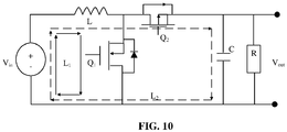
- FIG. 10 is a schematic diagram illustrating a conversion module according to an exemplary embodiment.
- L represents an inductor, configured to store electric energy when a circuit is switched on.
- a component Q 1 and a component Q 2 represent components with a switch function.
- the component Q 1 and the component Q 2 may be Metal Oxide Semiconductor (MOS) transistors.
- the duty ratio may be 0.25.
- the duty ratio is greater than 0 and less than 1
- (1- D ) is also greater than 0 and less than 1, so that the output voltage of the conversion module is higher than the input voltage input into the conversion module, namely the conversion module may realize the boosting function.
- the transistor Q 1 When the conversion module is in a first stage, the transistor Q 1 may be switched on, the transistor Q 2 may be switched off, a current may flow through a first loop (Li), and the input voltage V in provided by the power supply may act on the inductor L to enable the inductor L to store the electric energy.
- the inductor L storing the electric energy may be considered as an induction power supply, and an induced voltage V L thereof may positive on the left and negative on the right.
- Q 1 and Q 2 may be controlled to be switched on or switched off through the same pulse signal.
- the transistor Q 1 may be controlled to be switched off, and the transistor Q 2 may be controlled to be switched on.
- the conversion module may be in a second stage, the current may flow through a second loop (L2), and the inductor L may release the current.
- L2 second loop
- the induced voltage V L of the inductor L may change to be negative on the left and positive on the right, and a direction of the current released by the inductor L may be the same as a direction of an input current provided by the power supply.
- the output voltage of the conversion module may be considered as a superposition of the input voltage provided by the power supply and the induced voltage of the inductor L, so that the output voltage of the conversion module is higher than the input voltage provided by the power supply, namely a boosting process is completed.
- the first vibration component may be controlled to vibrate.
- the conversion module may convert the driving signal with the first signal value into the driving signal with the second signal value and transmit the driving signal with the second signal value to the first vibration component to apply a stronger driving force to the first vibration component.
- the damping force subjected to the first vibration component may be also stronger, so that both the vibration starting time and vibration stopping time of the first vibration component can be reduced.
- the signal value of the driving signal may be increased by the conversion module, the first vibration component 131 and/or the second vibration component 132 may be controlled by the driving signal with an increased signal value to vibrate.
- the driving signal with the second signal value compared with the driving signal with the first signal value, may generate a stronger vibration damping force when the first vibration component 131 and/or the second vibration component 132 start/starts vibration or stop/stops vibration. Therefore, an amplitude fading speed of the freely damped motion under the action of the vibration damping force may be increased to enable the first vibration component 131 and/or the second vibration component 132 to enter a steady state faster, namely the vibration starting time is shortened.
- the first vibration component 131 and/or the second vibration component 132 may only perform freely damped motions under the action of the vibration damping force, so that the vibration stopping time of the first vibration component 131 and/or the second vibration component 132 is also shortened, along with increase of the amplitude fading speed of the freely damped motion.
- the vibration starting time and the vibration stopping time may be shortened, and a transient vibration effect of the mobile terminal may be improved.
- the mobile terminal 100 may further include: a detection module, connected with the first vibration component 131 and the second vibration component 132, configured to detect a vibration frequency of the first vibration component 131 and/or a vibration frequency of the second vibration component 132 to obtain a detection result.
- a detection module connected with the first vibration component 131 and the second vibration component 132, configured to detect a vibration frequency of the first vibration component 131 and/or a vibration frequency of the second vibration component 132 to obtain a detection result.
- the processing module 140 may be connected with the detection module and configured to adjust the driving signal for controlling the first vibration component 131 and/or the second vibration component 132 to vibrate based on the detection result to control the vibration frequency of the first vibration component 131 and/or the vibration frequency of the second vibration component 132 within a preset frequency range.
- the preset frequency range may be from 100 hertz to 400 hertz.
- the vibration frequency of the first vibration component 131 is lower than 100 hertz, when the first display region 121 contacts with a human body, the human body may sense weak vibration and a vibration prompting effect is poor.
- the vibration frequency of the first vibration component 131 is higher than 400 hertz, when the first display region 121 contacts with the human body, the human body may feel a piercing pain like an electric shock and a user experience is poor.
- FIG. 11 is a schematic diagram illustrating the detection module for detecting the vibration frequency of the first vibration component.
- an electromotive force between a point E and a point F may be detected to detect a vibration effect of the first vibration component.
- an H bridge is a circuit structure formed by an MOS transistor and may enable a vibration function of the first vibration component or disenable the vibration function of the first vibration component by Pulse Width Modulation (PWM) control.
- PWM Pulse Width Modulation
- a control signal for controlling the first vibration component to vibrate may include two paths of differential signals, and the differential signals may be respectively transmitted to the first vibration component through a transmission line where the point E is and a transmission line where the point F is, and form the alternating magnetic field in the coil of the first vibration component.
- the detection module may detect a change of the alternating magnetic field to detect the vibration frequency of the first vibration component.
- time stamps may be added into the driving signal, and the vibration frequency of the first vibration component may be calculated by Fast Fourier Transform (FFT) according to a voltage value detected between the point E and the point F and the corresponding time stamp.
- FFT Fast Fourier Transform
- a driving frequency of the driving signal may be adjusted to control the vibration frequency of the first vibration component in the preset frequency range, namely locking the vibration frequency of the first vibration component.
- a resonance frequency of the first vibration component may be detected under the action of driving signals with different driving frequencies.
- a variation trend of the vibration frequency of the first vibration component may be the same as a variation trend of the driving frequency of the driving signal.
- FIG. 13 is a schematic diagram illustrating a detection module according to an exemplary embodiment. As shown in FIG.
- a Hall device in the detection module may output a Haul voltage (V H ) based on a Hall effect, and the Hall voltage may include a voltage signal reflecting a change of the alternating magnetic field and a Hall bias voltage signal, so that the Hall bias voltage signal may be removed through a bias circuit formed by a resistor R 1 and a resistor R 2 to ensure that a signal input into a first-stage operational amplifier is the voltage signal reflecting the change of the alternating magnetic field.
- V H Haul voltage
- the voltage signal reflecting the change of the alternating magnetic field may be sequentially amplified by the first-stage operational amplifier and amplified by a second-stage operational amplifier to increase a signal value thereof to be U 02 .
- An output voltage U 02 of the second-stage operational amplifier may be input into a sampling and holding circuit, and an output voltage of the sampling and holding circuit may be V 0 .
- V 0 represents the output voltage of the sampling and holding circuit and is configured to represent the amplified voltage signal reflecting the change of the alternating magnetic field, and V 0 is equal to the output voltage (U 02 ) of the second-stage operational amplifier.
- RF2 represents a resistance value of a resistor R F2 in the second-stage operational amplifier
- C F2 is a capacitance value of a capacitor C F2 in the second-stage operational amplifier
- R 5 represents a resistance value of a resistor R 5 in the second-stage operational amplifier
- U 01 represents an output voltage of the first-stage operational amplifier.
- V 0 may be input into a digital-to-analog conversion circuit as shown in FIG. 14 to implement comparison between a frequency of the voltage signal reflecting the change of the alternating magnetic field and a resonance frequency of the first vibration component. It can be understood that, when the output voltage of the sampling and holding circuit is transmitted to the digital-to-analog conversion circuit, an output voltage signal value of the sampling and holding circuit may be in a voltage range that may be sampled by the digital-to-analog conversion circuit.
- the transistor Q 1 may be controlled to be switched off to stop working of the sampling and holding circuit and a post circuit thereof, and meanwhile, electric charges stored by a capacitor C Q may be consumed through a resistor R 7 to reduce power consumption.
- a low-pass filter may further be included between an output end of the first-stage operational amplifier and an input end of the second-stage operational amplifier, and the low-pass filter is configured to filter a high-frequency noise component.
- the vibration frequency of the first vibration component and/or the vibration frequency of the second vibration component may be detected to obtain the detection result, and the driving signal for driving the first vibration component and/or the second vibration component to vibrate may be adjusted based on the detection result to control the vibration frequency of the first vibration component and/or the vibration frequency of the second vibration component in the preset frequency range, so that an effective vibration feedback may be provided for a user, and meanwhile, the probability of a poor user experience such as the piercing pain is reduced.
- FIG. 15 is a flow chart showing a vibration control method according to an exemplary embodiment. The method may be applied to the mobile terminal 100 provided in the embodiments of the present disclosure. As shown in FIG. 15 , the vibration control method includes the following steps.
- a form of a display screen is determined, the display screen having a folded form and an unfolded form, a first display region and a second display region being overlapped in the folded form and the first display region and the second display region being separated in the unfolded form.
- vibration amplitudes of a first vibration component arranged on a back surface of the first display region and a second vibration component arranged on a back surface of the second display region are controlled according to the form of the display screen.
- the form of the display screen may be determined, and the vibration amplitudes of the first vibration component and the second vibration component may be controlled according to the form of the display screen to further control a vibration amplitude of the mobile terminal, so that a requirement on control over the vibration amplitude of the mobile terminal in different forms of the display screen can be met, a foundation can be laid for improving consistency of vibration senses provided by the mobile terminal in the folded form and unfolded form of the display screen, and a user experience can be improved.
- S110 may include that:
- the first vibration component or the second vibration component may be controlled to vibrate at the first vibration amplitude or the first vibration component and the second vibration component may be controlled to vibrate at the second vibration amplitude lower than the first vibration amplitude, so that an interaction force between the first display region and the second display region during vibration may be reduced, impact of the interaction force on a vibration amplitude of the first display region or a vibration amplitude of the second display region may be reduced, and the consistency of the vibration amplitude in the folded form and unfolded form of the display screen can be improved, namely improvement of consistency of the vibration senses in the folded form and unfolded form of the display screen can be facilitated.
- controlling both the first vibration component and the second vibration component to vibrate in the unfolded form of the display screen in the present disclosure may avoid vibration sense deficiency, that is only one display region vibrates and the other display region does not vibrate in the unfolded form of the display screen, which is favorable for ensuring a vibration feedback effect.
- the method may further include that:
- a user can timely receive a vibration feedback by acquiring the state of the first display region and the state of the second display region in the folded form of the display screen and, when the user is required to be prompted, controlling the vibration component on the back surface of the display region in the working state to vibrate.
- the method may further include that:
- the included angle between the first display region and the second display region may be acquired, and the form of the display screen may be determined according to the included angle between the first display region and the second display region to further control the first vibration component and/or the second vibration component to vibrate.
- the method is simple.
- the operation that the included angle between the first display region and the second display region is acquired may include that:
- the attitude angle parameter of the first display region and the attitude angle parameter of the second display region may be acquired, and the included angle between the first display region and the second display region may be determined according to the attitude angle parameter of the first display region and the attitude angle parameter of the second display region.
- the method is highly compatible with the conventional art and simple.
- the method may further include that:
- the direction of the acceleration of the first display region and the direction of the acceleration of the second display region may be acquired through different acceleration sensors respectively.
- the accuracy of determining the included angle between the first display region and the second display region may be improved and the vibration control accuracy may further be improved, according to the direction of the acceleration of the first display region, the attitude angle parameter of the first display region, the direction of the acceleration of the second display region and the attitude angle parameter of the second display region.
- the method may further include that:
- the control module may directly generate a driving signal in a hardware triggering manner to control the first vibration component and/or the second vibration component to vibrate, so that a vibration response of the mobile terminal is quickened; or the processing module may generate a control signal and send the control signal to the control module through the communication interface and the control module may generate a driving signal.
- Various manners may be adopted for generating the driving signal, and a control manner is flexible.
- the method may further include that:
- the signal value of the driving signal may be increased by a conversion circuit, the first vibration component and/or the second vibration component may be controlled via the driving signal with an increased signal value to vibrate; and the driving signal with the second signal value, compared with the driving signal with the first signal value, may generate a stronger vibration damping force when the first vibration component and/or the second vibration component start/starts vibration or stop/stops vibration. Therefore, an amplitude fading speed of a freely damped motion under the action of the vibration damping force may be increased to enable the first vibration component and/or the second vibration component to enter a steady state faster, namely vibration starting time is shortened.
- the first vibration component and/or the second vibration component may only perform freely damped motions under the action of the vibration damping force, so that the vibration stopping time of the first vibration component and/or the second vibration component is also shortened, along with increase of the amplitude fading speed of the freely damped motion.
- the vibration starting time and the vibration stopping time may be shortened, and a transient vibration effect of the mobile terminal may be improved.
- the method may further include that:
- the vibration frequency of the first vibration component and/or the vibration frequency of the second vibration component may be detected to obtain the detection result, and the driving signal for driving the first vibration component and/or the second vibration component to vibrate may be adjusted based on the detection result to control the vibration frequency of the first vibration component and/or the vibration frequency of the second vibration component within the preset frequency range, so that an effective vibration feedback may be provided for a user, and meanwhile, the probability of a poor user experience such as the piercing pain is reduced.
- a first vibration component may be controlled to vibrate.
- the vibration mechanical model may include the first vibration component and a mobile terminal.
- F represents an acting force applied to the mobile terminal by vibration of the first vibration component.
- M represents the mass of the mobile terminal.
- A represents an acceleration generated by the mobile terminal under the action of vibration of the first vibration component.
- G represents a vibrational touch unit of the mobile terminal.
- a represents an acceleration of the first vibration component in a vibration process.
- T represents a vibrational touch unit amplification coefficient of the first vibration component.
- m represents the mass of the first vibration component.
- D represents a vibration amplitude of the first vibration component.
- f represents a vibration frequency
- g represents a gravitational acceleration.
- a vibration sensor may be arranged at any part of the mobile terminal, and an acceleration of a mechanical load when motor vibrator drives the mobile terminal to vibrate may be tested through an acceleration test device.
- the whole mobile terminal may have a three-dimensional acceleration spatial distribution function.
- a maximum value A max of the acceleration of the mobile terminal may be determined to determine a maximum vibrational touch unit, and whether a vibration effect meets a requirement may be further determined according to a relationship between the maximum vibrational touch unit and a preset vibrational touch unit range.
- the maximum vibrational touch unit when the maximum vibrational touch unit is in the preset vibrational touch unit range, it may be determined that the required vibration effect meets the requirement; and when the maximum vibrational touch unit is not in the preset vibrational touch unit range, it may be determined that the vibration effect does not meet the requirement.
- the below is a mechanical model deduction process of the first vibration component according to an exemplary embodiment.
- e x is an x -axis unit component and e y is a y -axis unit component.
- the mass of the first vibration component is m
- a tangential velocity of a motion of the first vibration component is v
- an x -axis velocity component of the first vibration component is v x
- a y -axis velocity component is v y
- an included angle between a velocity vector v and the axis x is ⁇
- an initial velocity of the first vibration component is v 0
- a rotation angular velocity of the first vibration component is ⁇
- the acceleration of the first vibration component is a
- a radius for a circular motion of the first vibration component is r
- a centripetal force applied to the first vibration component is F 1
- a vibration quantity ⁇ may meet the following directional proportional relationship: ⁇ ⁇ mD 2 ⁇ f 2 M where D represents the vibration amplitude of the first vibration component, the frequency of the driving force being the same as the vibration frequency of the first vibration component.
- the vibration quantity may usually be represented by a ratio of the acceleration a to the gravitational acceleration g .
- a vibration quantity of 2 g represents that the vibration quantity is twice the gravitational acceleration g .
- the amplification coefficient Z may be about 2.7 or 2 ⁇ 2.
- the theoretical vibration quantity may be obtained by dividing an obtained amplitude by 2 to obtain an effective value and dividing the effective value by the gravitational acceleration g , and is configured to measure vibration sensed by a user.
- the vibration quantity is related to the mass m of the first vibration component, the vibration amplitude D of the first vibration component and the frequency f of the driving force.
- the vibration amplitude D in the formula (12) may be not directly determined by the mass of the first vibration component but may be impacted by a damping coefficient and required to be independently researched.
- a damping force may be determined by considering the first vibration component as a viscous damping model.
- the viscous damping model may include a spring and a mass block which is connected with the spring and vibrates under the action of the driving force.
- F d cv
- F d represents an overall damping force
- c represents a viscous damping coefficient taking N ⁇ s / m as a unit.
- a 1 e - ⁇ t sin( ⁇ d t+ ⁇ ) represents a freely damped motion
- B 1 sin( ⁇ t - ⁇ ) represents a driven motion of the first vibration component driven by the driving signal output by the mobile terminal under the action of an internal Lorentz force.
- D B 1 sin ⁇ t ⁇ ⁇ where B 1 represents a first vibration amplitude, and ⁇ represents a phase difference between a displacement phase of the first vibration component and a phase of the driving signal.
- the formula (17) may be configured to represent a steady response relationship of controlling the first vibration component to vibrate in an alternating magnetic field generated by the driving signal output by a control module in a coil of the first vibration component.
- a ratio of the first vibration amplitude B 1 to the second vibration amplitude B 0 is represented as a vibration amplitude amplification factor ⁇ , as shown in the formula (20).
- the vibration amplitude amplification factor ⁇ is maximum.
- ⁇ 1 2 ⁇
- the phase difference between the phase of the driving force generated by the driving signal and the displacement phase is ⁇ /2. It is indicated that the driving force is maximum when the displacement of the mass block is 0 and that the driving force is 0 when the displacement of the mass block is maximum.
- FIG. 8 is a damped vibration curve according to an exemplary embodiment.
- a vibration state of the first vibration component may be switched from steady vibration to simple harmonic vibration with the vibration amplitude fading according to an exponential rule, called damped vibration.
- ⁇ d ⁇ n 1 ⁇ ⁇ 2 .
- the amplitude fading coefficient is configured to represent a fading speed.
- braking time t brake represents time when the vibration quantity of the first vibration component is reduced from 100% to 10%. It can be known according to the equation (26) that, in the damping process that the vibration quantity of the first vibration component is reduced from 100% to 10%, if the damping ratio of the first vibration component is higher, the braking time is shorter.
- the braking time t brake may be considered as a required time length from a moment when the driving force on the first vibration component is released to a moment when the first vibration component stops vibration.
- D t e ⁇ ⁇ n t D 0 cos ⁇ d + D ⁇ 0 + ⁇ n D 0 ⁇ d Ssin ⁇ d t + B 1 e ⁇ ⁇ n t sin ⁇ cos ⁇ d + ⁇ n ⁇ d ⁇ sin ⁇ ⁇ ⁇ cos ⁇ sin ⁇ d t + B 1 sin ⁇ t ⁇ ⁇
- the formula (29) may represent the driven motion of the first vibration component under the internal Lorentz force.
- FIG. 16 is a block diagram of a vibration control device 800 according to an exemplary embodiment.
- the device 800 may be a mobile phone, a computer, a digital broadcast terminal, a messaging device, a gaming console, a tablet, a medical device, exercise equipment, a personal digital assistant and the like.
- the device 800 may include one or more of the following components: a processing component 802, a memory 804, a power component 806, a multimedia component 808, an audio component 810, an Input/Output (I/O) interface 812, a sensor component 814, and a communication component 816.
- a processing component 802 a memory 804, a power component 806, a multimedia component 808, an audio component 810, an Input/Output (I/O) interface 812, a sensor component 814, and a communication component 816.
- the processing component 802 is typically configured to control overall operations of the device 800, such as the operations associated with display, telephone calls, data communications, camera operations, and recording operations.
- the processing component 802 may include one or more processors 820 to execute instructions to perform all or part of the steps in the abovementioned method.
- the processing component 802 may further include one or more modules which facilitate interaction between the processing component 802 and the other components.
- the processing component 802 may include a multimedia module to facilitate interaction between the multimedia component 808 and the processing component 802.
- the memory 804 is configured to store various types of data to support the operation of the device 800. Examples of such data include instructions for any applications or methods operated on the device 800, contact data, phonebook data, messages, pictures, video, etc.
- the memory 804 may be implemented by any type of volatile or non-volatile memory devices, or a combination thereof, such as a Static Random Access Memory (SRAM), an Electrically Erasable Programmable Read-Only Memory (EEPROM), an Erasable Programmable Read-Only Memory (EPROM), a Programmable Read-Only Memory (PROM), a Read-Only Memory (ROM), a magnetic memory, a flash memory, and a magnetic or optical disk.
- SRAM Static Random Access Memory
- EEPROM Electrically Erasable Programmable Read-Only Memory
- EPROM Erasable Programmable Read-Only Memory
- PROM Programmable Read-Only Memory
- ROM Read-Only Memory
- magnetic memory a magnetic memory
- flash memory and a magnetic or optical disk.
- the power component 806 is configured to provide power for various components of the device 800.
- the power component 806 may include a power management system, one or more power supplies, and other components associated with generation, management and distribution of power for the device 800.
- the multimedia component 808 may include a screen providing an output interface between the device 800 and a user.
- the screen may include a Liquid Crystal Display (LCD) and a Touch Panel (TP). If the screen includes the TP, the screen may be implemented as a touch screen to receive an input signal from the user.
- the TP includes one or more touch sensors to sense touches, swipes and gestures on the TP. The touch sensors may not only sense a boundary of a touch or swipe action but also detect a duration and pressure associated with the touch or swipe action.
- the multimedia component 808 includes a front camera and/or a rear camera.
- the front camera and/or the rear camera may receive external multimedia data when the device 800 is in an operation mode, such as a photographing mode or a video mode.
- an operation mode such as a photographing mode or a video mode.
- Each of the front camera and/or the rear camera may be a fixed optical lens system or have focusing and optical zooming capabilities.
- the audio component 810 is configured to output and/or input an audio signal.
- the audio component 810 includes a Microphone (MIC), and the MIC is configured to receive an external audio signal when the device 800 is in the operation mode, such as a call mode, a recording mode and a voice recognition mode.
- the received audio signal may further be stored in the memory 804 or sent through the communication component 816.
- the audio component 810 further includes a speaker configured to output the audio signal.
- the I/O interface 812 is configured to provide an interface between the processing component 802 and a peripheral interface module, and the peripheral interface module may be a keyboard, a click wheel, a button and the like.
- the button may include, but not limited to: a home button, a volume button, a starting button and a locking button.
- the sensor component 814 may include one or more sensors configured to provide status assessment in various aspects for the device 800. For instance, the sensor component 814 may detect an on/off status of the device 800 and relative positioning of components, such as a display and small keyboard of the device 800, and the sensor component 814 may further detect a change in a position of the device 800 or a component of the device 800, presence or absence of contact between the user and the device 800, orientation or acceleration/deceleration of the device 800 and a change in temperature of the device 800.
- the sensor component 814 may include a proximity sensor configured to detect presence of an object nearby without any physical contact.
- the sensor component 814 may also include a light sensor, such as a Complementary Metal Oxide Semiconductor (CMOS) or Charge Coupled Device (CCD) image sensor, configured for use in an imaging application.
- CMOS Complementary Metal Oxide Semiconductor
- CCD Charge Coupled Device
- the sensor component 814 may also include an acceleration sensor, a gyroscope sensor, a magnetic sensor, a pressure sensor or a temperature sensor.
- the communication component 816 is configured to facilitate wired or wireless communication between the device 800 and another device.
- the device 800 may access a communication-standard-based wireless network, such as a Wireless Fidelity (WiFi) network, a 2nd-Generation (2G) or 3rd-Generation (3G) network or a combination thereof.
- WiFi Wireless Fidelity
- 2G 2nd-Generation
- 3G 3rd-Generation
- the communication component 816 receives a broadcast signal or broadcast associated information from an external broadcast management system through a broadcast channel.
- the communication component 816 further includes a Near Field Communication (NFC) module to facilitate short-range communication.
- NFC Near Field Communication
- the NFC module may be implemented based on a Radio Frequency Identification (RFID) technology, an Infrared Data Association (IrDA) technology, an Ultra-WideBand (UWB) technology, a Bluetooth (BT) technology or another technology.
- RFID Radio Frequency Identification
- IrDA Infrared Data Association
- UWB Ultra-WideBand
- BT Bluetooth
- the device 800 may be implemented by one or more Application Specific Integrated Circuits (ASICs), Digital Signal Processors (DSPs), Digital Signal Processing Devices (DSPDs), Programmable Logic Devices (PLDs), Field Programmable Gate Arrays (FPGAs), controllers, micro-controllers, microprocessors or other electronic components, and is configured to execute the abovementioned method.
- ASICs Application Specific Integrated Circuits
- DSPs Digital Signal Processors
- DSPDs Digital Signal Processing Devices
- PLDs Programmable Logic Devices
- FPGAs Field Programmable Gate Arrays
- controllers micro-controllers, microprocessors or other electronic components, and is configured to execute the abovementioned method.
- a non-transitory computer-readable storage medium including instructions, such as the memory 804 including instructions, and the instructions may be executed by the processor 820 of the device 800 to implement the vibration control method.
- the non-transitory computer-readable storage medium may be a ROM, a Random Access Memory (RAM), a Compact Disc Read-Only Memory (CD-ROM), a magnetic tape, a floppy disc, an optical data storage device and the like.
- instructions in the storage medium may be executed by a processor of a mobile terminal to enable the mobile terminal to implement the steps in the vibration control method provided in the embodiments of the present disclosure.
Abstract
Description
- The present disclosure generally relates to the technical field of mobile terminals, and more particularly, to a mobile terminal, a vibration control method and device, and a storage medium.
- Vibration is one of commonly used functions of a mobile terminal. For example, when a mobile terminal receives an incoming call or a short message, the mobile terminal may prompt a user by vibration such that the user can timely check the mobile terminal.
- However, some mobile terminals with folding screens may provide inconsistent vibration senses during vibration, resulting in degraded user experience. Therefore, how to improve a vibration effect of a mobile terminal with a folding screen is a problem to be further solved.
- In view of this, the present disclosure provides a mobile terminal, a vibration control method and device and a storage medium.
- According to a first aspect of embodiments of the present disclosure, a mobile terminal may include:
- a shell;
- a display screen, arranged on a surface of the shell, including a first display region and a second display region;
- a first vibration component, arranged in the shell and on a back surface of the first display region;
- a second vibration component, arranged in the shell and on a back surface of the second display region;
- a processing module, arranged in the shell, configured to determine a form of the display screen, the display screen having a folded form and an unfolded form, the first display region and the second display region are overlapped in the folded form and the first display region and the second display region being separated in the unfolded form; and
- a control module, arranged in the shell and connected with the processing module, the first vibration component and the second vibration component, configured to control vibration amplitudes of the first vibration component and the second vibration component according to the form of the display screen.
- According to a second aspect of the embodiments of the present disclosure, a vibration control method may be applied to the mobile terminal provided according to the first aspect of the embodiments of the present disclosure and include:
- determining the form of the display screen, where the display screen has the folded form and the unfolded form, the first display region and the second display region are overlapped in the folded form, and the first display region and the second display region are separated in the unfolded form; and
- controlling the vibration amplitudes of the first vibration component arranged on the back surface of the first display region and the second vibration component arranged on the back surface of the second display region according to the form of the display screen.
- According to a third aspect of the embodiments of the present disclosure, a vibration control device may include:
- a processor; and
- a memory configured to store instructions executable by the processor,
- wherein the processor may be configured to execute the instructions to implement the steps in the vibration control method according to the second aspect of the embodiments of the present disclosure.
- According to a fourth aspect of the embodiments of the present disclosure, a non-transitory computer-readable storage medium is provided, which may have instructions stored thereon that, when executed by a processor of a mobile terminal, enable the mobile terminal to implement the steps in the vibration control method according to the second aspect of the embodiments of the present disclosure.
- The technical solutions provided by embodiments of the present disclosure may have the following beneficial effects.
- When a display screen is in a folded form, if both the first vibration component and the second vibration component are controlled to vibrate at vibration amplitudes the same as those in an unfolded state of the display screen, the vibration amplitudes of the first display region and the second display region may be increased due to an interaction force between the first display region and the second display region, a vibration amplitude of the mobile terminal with the display screen in the folded form may be higher than the vibration amplitude of the mobile terminal with the display screen in the unfolded form. As a result, a user may have different vibration senses experiences when the display screen is in the folded form and in the unfolded form.
- According to the present disclosure, the form of the display screen may be determined through the processing module, and the vibration amplitudes of the first vibration component and the second vibration component may be controlled according to the form of the display screen to further control the vibration amplitude of the mobile terminal, so that a requirement on control over the vibration amplitude of the mobile terminal in different forms of the display screen can be met, a foundation can be laid for improving consistency of the vibration senses provided by the mobile terminal in the folded form and unfolded form of the display screen, and a user experience can be improved.
- It is to be understood that the above general descriptions and detailed descriptions below are only exemplary and explanatory and not intended to limit the present disclosure.
- The accompanying drawings, which are incorporated in and constitute a part of this specification, illustrate embodiments consistent with the present disclosure and, together with the description, serve to explain the principles of the present disclosure.
-
FIG. 1 is a block diagram of a mobile terminal according to an exemplary embodiment. -
FIG. 2 is a block diagram of another mobile terminal according to an exemplary embodiment. -
FIG. 3A is a schematic diagram illustrating a mobile terminal in an unfolded form according to an exemplary embodiment. -
FIG. 3B is a schematic diagram illustrating another mobile terminal in an unfolded form according to an exemplary embodiment. -
FIG. 3C is a schematic diagram illustrating a mobile terminal in a folded form according to an exemplary embodiment. -
FIG. 3D is a schematic diagram illustrating another mobile terminal in a folded form according to an exemplary embodiment. -
FIG. 4 is a schematic diagram illustrating a signal curve according to an exemplary embodiment. -
FIG. 5 is a schematic diagram illustrating another signal curve according to an exemplary embodiment. -
FIG. 6 is a schematic diagram illustrating a freely damped motion according to an exemplary embodiment. -
FIG. 7 is a schematic diagram illustrating a steady motion according to an exemplary embodiment. -
FIG. 8 is a motion diagram of a vibration start process according to an exemplary embodiment. -
FIG. 9 is a motion diagram of a vibration stop process according to an exemplary embodiment. -
FIG. 10 is a schematic diagram illustrating a conversion module according to an exemplary embodiment. -
FIG. 11 is a partial diagram of a mobile terminal according to an exemplary embodiment. -
FIG. 12 is a structure diagram of an H-bridge circuit according to an exemplary embodiment. -
FIG. 13 is a schematic diagram illustrating a detection module according to an exemplary embodiment. -
FIG. 14 is a schematic diagram illustrating a digital-to-analog conversion circuit according to an exemplary embodiment. -
FIG. 15 is a flow chart showing a vibration control method according to an exemplary embodiment. -
FIG. 16 is a block diagram of a vibration control device according to an exemplary embodiment. - Reference will now be made in detail to exemplary embodiments, examples of which are illustrated in the accompanying drawings. The following description refers to the accompanying drawings in which the same numbers in different drawings represent the same or similar elements unless otherwise represented. The implementations set forth in the following description of exemplary embodiments do not represent all implementations consistent with the present disclosure. Instead, they are merely examples of apparatuses and methods consistent with aspects related to the present disclosure as recited in the appended claims.
- Along with gradual development of electronic device technologies, a display screen with a folding display region is one of development trends. A display screen may include a first display region and a second display region. The display screen may have a folded form and an unfolded form. In the folded form, the first display region and the second display region are overlapped. In the unfolded form, the first display region and the second display region are separated.
- A vibration component arranged on a back surface of a display region may usually be controlled to vibrate to enable the display region to vibrate.
- When a first vibration component on a back surface of the first display region vibrates, the first vibration component may apply a first acting force to the first display region, and the first display region may vibrate under the action of the first acting force.
- When a second vibration component on a back surface of the second display region vibrates, the second vibration component may apply a second acting force to the second display region, and the second display region may vibrate under the action of the second acting force.
- When the display screen is in the unfolded form and both the first vibration component and the second vibration component vibrate according to a preset vibration mode, an interaction force between the first display region and the second display region can be weaker. In such a case, the first display region and the second display region may also vibrate according to the preset vibration mode.
- When the display screen is in the folded form, if both the vibration component and the second vibration component vibrate, the interaction force between the first display region and the second display region can be strengthened to increase vibration amplitudes of the first display region and the second display region. A vibration amplitude of a mobile terminal with the display screen in the folded form may be higher than the vibration amplitude of the mobile terminal with the display screen in the unfolded form. As a result, vibration senses experienced by a user in the folded form and unfolded form of the display screen may be different.
- That is, in the related art, a user holding a mobile device with a foldable display screen may have greatly different vibration senses experiences when the display screen is in the unfolded form and the display screen is in the folded form, which is unfavorable for improving a user experience.
-
FIG. 1 is a schematic diagram illustrating amobile terminal 100 according to an exemplary embodiment. As shown inFIG. 1 , themobile terminal 100 includes: - a
shell 110; - a
display screen 120, arranged on a surface of theshell 110, including afirst display region 121 and asecond display region 122; - a
first vibration component 131, arranged in theshell 110 and on a back surface of thefirst display region 121; - a
second vibration component 132, arranged in theshell 110 and on a back surface of thesecond display region 122; - a
processing module 140, arranged in the shell, configured to determine a form of thedisplay screen 120, where thedisplay screen 120 have a folded form and an unfolded form, thefirst display region 121 and thesecond display region 122 are overlapped in the folded form, and thefirst display region 121 and thesecond display region 122 are separated in the unfolded form; and - a
control module 150, arranged in theshell 110 and connected with theprocessing module 140, thefirst vibration component 131 and thesecond vibration component 132, configured to control vibration amplitudes of thefirst vibration component 131 and thesecond vibration component 132 according to the form of thedisplay screen 120. - When the
first display region 121 and thesecond display region 122 are overlapped, thefirst display region 121 may be arranged on a first surface of themobile terminal 100, and thesecond display region 122 may be arranged on a second surface of themobile terminal 100, the first surface of themobile terminal 100 and the second surface of themobile terminal 100 being opposite surfaces. - When the
first display region 121 and thesecond display region 122 are separated, an orientation of a display surface of thefirst display region 121 may be consistent with an orientation of a display surface of thesecond display region 122. For example, both the display surface of thefirst display region 121 and the display surface of thesecond display region 122 may face a user. When thefirst display region 121 and thesecond display region 122 are separated, the orientation of the display surface of thefirst display region 121 may form a certain included angle with the orientation of the display surface of thesecond display region 122. - According to the present disclosure, the form of the display screen may be determined through the processing module, and the vibration amplitudes of the first vibration component and the second vibration component may be controlled according to the form of the display screen to further control a vibration amplitude of the mobile terminal, so that a requirement on control over the vibration amplitude of the mobile terminal in different forms of the display screen may be met, a foundation may be laid for improving consistency of vibration senses provided by the mobile terminal when the display screen is in the folded form and in the unfolded form, and a user experience can be improved.
- In some implementations, the
shell 100 may include: - a rear cover, and
- a middle frame; and
- the
first vibration component 131 and thesecond vibration component 132 are arranged on the middle frame, or, the first vibration component and the second vibration component are arranged in different edge regions of the rear cover. - The rear cover may include a cover body configured to support or bear various parts in the mobile terminal.
- A first region of the rear cover may be parallel to the first display region, and a second region of the rear cover may be parallel to the second display region. The first vibration component may be arranged in an edge region of the first region of the rear cover, and the second vibration component may be arranged in an edge region of the second region of the rear cover.
- Compared with arranging the first vibration component in a middle region of the first region of the rear cover, arranging the first vibration component in the edge region of the first region of the rear cover in the embodiments of the present disclosure may drive the rear cover more easily to make an obvious vibration, which is favorable for ensuring a vibration effect.
- The middle frame may be perpendicular to a plane where the rear cover is, may surround an edge of the rear cover and may be configured for arrangement of a part such as a button and a jack.
- For enabling a user to sense vibration more obviously, the first vibration component may be arranged at a place, contacting with the middle frame, on the back surface of the first display region, and the second vibration component may be arranged at a place, contacting with the middle frame, on the back surface of the second display region. When the first vibration component vibrates, the first display region and the middle frame may be driven to vibrate, such that a part of the user holding the mobile terminal or contacting with the mobile terminal, such as a hand, may sense the vibration more obviously.
- In some implementations, the
control module 150 is configured to, when thedisplay screen 120 is in the unfolded form, control thefirst vibration component 131 and thesecond vibration component 132 to vibrate at a first vibration amplitude. - The
control module 150 is further configured to, when thedisplay screen 120 is in the folded form, control thefirst vibration component 131 or thesecond vibration component 132 to vibrate at the first vibration amplitude; and thecontrol module 150 is further configured to, when thedisplay screen 120 is in the folded form, control thefirst vibration component 131 and thesecond vibration component 132 to vibrate at a second vibration amplitude, the second vibration amplitude being lower than the first vibration amplitude. - When the display screen is in the folded form, the
control module 150 may control thefirst vibration component 131 or thesecond vibration component 132 to vibrate at the first vibration amplitude or control thefirst vibration component 131 and thesecond vibration component 132 to vibrate at the second vibration amplitude lower than the first vibration amplitude, so that the interaction force between thefirst display region 121 and thesecond display region 122 during vibration can be reduced, the impact of the interaction force on a vibration amplitude of thefirst display region 121 or a vibration amplitude of thesecond display region 122 can be reduced, and the consistency of the vibration amplitudes when thedisplay screen 120 is in the folded form and in the unfolded form can be improved, namely the consistency of vibration senses when thedisplay screen 120 is in the folded form and in the unfolded form can be improved. - In addition, compared with only controlling the
first vibration component 131 or thesecond vibration component 132 to vibrate when the display screen is in the unfolded form to cause vibration sense deficiency, controlling both thefirst vibration component 131 and thesecond vibration component 132 to vibrate when thedisplay screen 120 is in the unfolded form in the present disclosure may avoid vibration sense deficiency that is only one display region vibrates while the other display region does not vibrate in the unfolded form of thedisplay screen 120, which is favorable for ensuring the vibration effect. - In some implementations, the
mobile terminal 100 may further include:
a state acquisition module, arranged in theshell 110 and connected with thecontrol module 150, configured toacquire a state of thefirst display region 121 and a state of thesecond display region 122 when thedisplay screen 120 is in the folded form, each of the state of thefirst display region 121 and the state of thesecond display region 122 including a working state and an idle state. - The
control module 150 is specifically configured to control thefirst vibration component 131 to vibrate, when thedisplay screen 120 is in the folded form, thefirst display region 121 is in the working state and thesecond display region 122 is in the idle state. - The
control component 150 is further specifically configured to control thesecond vibration component 132 to vibrate, when thedisplay screen 120 is in the folded form, thefirst display region 121 is in the idle state and thesecond display region 122 is in the working state. - The state acquisition module may acquire the state of the
first display region 121 and the state of thesecond display region 122 in a manner of acquiring power consumption of thefirst display region 121 and thesecond display region 122 and comparing the power consumption of thefirst display region 121 and the power consumption of thesecond display region 122 with preset power consumption. Herein, the preset power consumption may represent minimum power consumption required by the display region in the working state. - Specifically, when the power consumption of the
first display region 121 is higher than the preset power consumption, thefirst display region 121 may be in the working state. When the power consumption of thefirst display region 121 is lower than the preset power consumption, thefirst display region 121 may be in the idle state. - When the power consumption of the
second display region 122 is higher than the preset power consumption, thesecond display region 122 may be in the working state. When the power consumption of thesecond display region 122 is lower than the preset power consumption, thesecond display region 122 may be in the idle state. - In an example, the working state may include a state that a user operation instruction may be received. For example, when the
first display region 121 is in the working state, a video may be played in thefirst display region 121, and in such a case, a user may execute a pressing operation on a specific area of thefirst display region 121 to trigger the mobile terminal to pause the presently played video. Herein, the specific area of thefirst display region 121 may be a preset area capable of sensing the pressing operation. - It can be understood that, when the
first display region 121 is in the working state, the display surface of thefirst display region 121 usually faces a user. When thesecond display region 122 is in the working state, the display surface of thesecond display region 122 usually faces a user. - In an example, the idle state may include a state of displaying nothing or a state of displaying a specific picture, etc. For example, when the
second display region 122 is in the idle state, displaying may be stopped in thesecond display region 122, or the specific picture may be displayed in thesecond display region 122. Herein, the specific picture may be a static picture or a dynamic picture set depending on a user requirement. - It is to be noted that, when the
display screen 120 is in the folded form, thefirst display region 121 may be in the working state and thesecond display region 122 may be in the idle state, the display surface of thefirst display region 121 may face a user and the display surface of thesecond display region 122 may be back on to the user. - When the
display screen 120 is in the folded form, thefirst display region 121 may be in the idle state and thesecond display region 122 may be in the working state, the display surface of thefirst display region 121 may be back on to the user and the display surface of thesecond display region 122 may face the user. - Compared with driving the vibration component on the back surface of the display region in the idle state to vibrate when the user is required to be prompted, a user may be guaranteed to timely receive a vibration by acquiring both the state of the
first display region 121 and the state of thesecond display region 122 in the folded form of thedisplay screen 120 and, when the user is required to be prompted, controlling the vibration component on the back surface of the display region in the working state to vibrate. - In some implementations, as shown in
FIG. 2 , themobile terminal 100 may further include:
an includedangle acquisition module 160, arranged in theshell 110 and connected with theprocessing module 140, configured to acquire an included angle between thefirst display region 121 and thesecond display region 122. - The
processing module 140 is specifically configured to, when the included angle between thefirst display region 121 and thesecond display region 122 is smaller than or equal to a first preset angle, determine that thedisplay screen 120 is in the folded form. - The
processing module 140 is further specifically configured to, when an included angle between the orientation of the display surface of thefirst display region 121 and the orientation of the display surface of thesecond display region 122 is larger than the first preset angle, determine that thedisplay screen 120 is in the unfolded form. - Herein, the included angle between the
first display region 121 and thesecond display region 122 may be defined as an angle larger than or equal to 0 degree and smaller than or equal to 180 degrees. - Specifically, the included angle between the
first display region 121 and thesecond display region 122 may include an included angle between the display surface of thefirst display region 121 and the display surface of thesecond display region 122, or an included angle between the display surface of thefirst display region 121 and the back surface of thesecond display region 122, or an included angle between the back surface of thefirst display region 121 and the display surface of thesecond display region 122, or an included angle between the back surface of thefirst display region 121 and the back surface of thesecond display region 122. The back surface of thefirst display region 121 may be an opposite side of the display surface of thefirst display region 121, and the back surface of thesecond display region 122 may be an opposite side of the display surface of thesecond display region 122. - In an example, the first preset angle may be 90 degrees.
- Specifically, when the included angle between the display surface of the
first display region 121 and the display surface of thesecond display region 122 is larger than 90 degrees and smaller than 180 degrees, themobile terminal 100 may be in a form as shown inFIG. 3A . In such a case, thedisplay screen 120 is in the unfolded form. - When the included angle between the display surface of the
first display region 121 and the display surface of thesecond display region 122 is equal to 180 degrees, themobile terminal 100 may be in a form as shown inFIG. 3B . In such a case, thedisplay screen 120 is in the unfolded form. - Referring to
FIG. 3B , when the eyes of a user are at a position "1", it may be considered that both the display surface of thefirst display region 121 and the display surface of thesecond display region 122 face the user. In such a case, thefirst display region 121 and thesecond display region 122 may simultaneously implement displaying. - When the eyes of the user are at a position "2", the user may face the back surfaces of the
first display region 121 and thesecond display region 122. It may be considered that both the display surface of thefirst display region 121 and the display surface of thesecond display region 122 are back on to the user. - For another example, when the included angle between the back surface of the
first display region 121 and the back surface of thesecond display region 122 is larger than 0 degree and smaller than 90 degrees, themobile terminal 100 may be in a form as shown inFIG. 3C . In such a case, thedisplay screen 120 is in the folded form. When the included angle between the back surface of thefirst display region 121 and the back surface of thesecond display region 122 is equal to 0 degree, themobile terminal 100 may be in a form as shown inFIG. 3D . - Referring to
FIG. 3D , when the eyes of the user are at a position "3", it may be considered that the display surface of thefirst display region 121 faces the user and the display surface of thesecond display region 122 is back on to the user. In such a case, thefirst display region 121 is often in the working state and thesecond display region 122 is often in the idle state. - When the eyes of the user are at a position "4", it may be considered that the display surface of the
first display region 121 is back on to the user and the display surface of thesecond display region 122 faces the user. In such a case, thefirst display region 121 is usually in the idle state and thesecond display region 122 is usually in the working state. - In the embodiments of the present disclosure, the included angle between the
first display region 121 and thesecond display region 122 may be acquired, and the form of the display screen may be determined according to the included angle between thefirst display region 121 and thesecond display region 122 to further control the vibration amplitudes of thefirst vibration component 131 and thesecond vibration component 132. The method is simple. - In some implementations, the included
angle acquisition module 160 may include: - a first angular velocity sensor, arranged on the back surface of the
first display region 121, configured to acquire an attitude angle parameter of thefirst display region 121, and - a second angular velocity sensor, arranged on the back surface of the
second display region 122, configured to acquire an attitude angle parameter of thesecond display region 122. - The included
angle acquisition module 160 is specifically configured to determine the included angle between thefirst display region 121 and thesecond display region 122 according to the attitude angle parameter of thefirst display region 121 and the attitude angle parameter of thesecond display region 122. - Both the first angular velocity sensor and the second angular velocity sensor may be gyroscopes. The attitude angle parameter of the
first display region 121 is configured to represent a rotation angle of thefirst display region 121. The attitude angle parameter of thesecond display region 122 is configured to represent a rotation angle of thesecond display region 122. - In an example, the
mobile terminal 100 may pre-store the attitude angle parameter of thefirst display region 121 and attitude angle parameter of thesecond display region 122, acquired when a previous driving signal is generated, as well as a driving result of the previous driving signal. Based on the previous driving result, the vibration component that vibrates when the previous driving signal is generated may be determined. - In an example, when the previous driving result is controlling the
first vibration component 131 and thesecond vibration component 132 to vibrate at the first vibration amplitude, thedisplay screen 120 may be in the unfolded form during previous vibration. Furthermore, a presently acquired attitude angle parameter of thefirst display region 121 may be compared with a previously acquired attitude angle parameter of thefirst display region 121 to determine a change of an attitude angle of thefirst display region 121 relative to that when the previous driving signal is generated. A presently acquired attitude angle parameter of thesecond display region 122 may be compared with a previously acquired attitude angle parameter of thesecond display region 122 to determine a change of an attitude angle of thesecond display region 122 relative to that when the previous driving signal is generated. In such a manner, a change value of the included angle between thefirst display region 121 and thesecond display region 122 relative to that when the previous driving signal is generated may be determined, namely a present included angle between thefirst display region 121 and thesecond display region 122 may be determined. - In the embodiments of the present disclosure, the attitude angle parameter of the
first display region 121 and the attitude angle parameter of thesecond display region 122 may be acquired, and the included angle between thefirst display region 121 and thesecond display region 122 may be determined according to the attitude angle parameter of thefirst display region 121 and the attitude angle parameter of thesecond display region 122. The method is highly compatible with the conventional art and is simple. - In some implementations, the included
angle acquisition module 160 may further include: - a first acceleration sensor, arranged on the back surface of the
first display region 121, configured to acquire an acceleration of thefirst display region 121, and - a second acceleration sensor, arranged on the back surface of the
second display region 122, configured to acquire an acceleration of thesecond display region 122. - The included
angle acquisition module 160 is specifically configured to determine the included angle between thefirst display region 121 and thesecond display region 122 according to a direction of the acceleration of thefirst display region 121, the attitude angle parameter of thefirst display region 121, a direction of the acceleration of thesecond display region 122 and the attitude angle parameter of thesecond display region 122. - In an example, the included
angle acquisition module 160 may judge whether a direction of the acceleration of thefirst display region 121 is consistent with a direction of the acceleration of thesecond display region 122 to determine whether the orientation of the display surface of thefirst display region 121 is consistent with the orientation of the display surface of thesecond display region 122 to further determine the form of thedisplay screen 120. - Specifically, when a direction of the acceleration of the
first display region 121 is consistent with a direction of the acceleration of thesecond display region 122, the orientation of the display surface of thefirst display region 121 can be consistent with the orientation of the display surface of thesecond display region 122, and thedisplay screen 120 may be in the unfolded form. - When a direction of the acceleration of the
first display region 121 is opposite to a direction of the acceleration of thesecond display region 122, the orientation of the display surface of thefirst display region 121 may be opposite to the orientation of the display surface of thesecond display region 122, and thedisplay screen 120 may be in the folded form. - For example, a z-axis component direction of an acceleration of the
first display region 121 and a z-axis component direction of an acceleration of thesecond display region 122 in a three-dimensional coordinate system may be determined according to a direction of the acceleration of thefirst display region 121, the attitude angle parameter of thefirst display region 121, a direction of the acceleration of thesecond display region 122 and the attitude angle parameter of thesecond display region 122. Herein, it may be considered that the three-dimensional coordinate system is a geographic coordinate system and a positive z-axis direction may be opposite to a gravity direction of themobile terminal 100. - Specifically, when the z-axis component direction of the acceleration of the
first display region 121 is consistent with the positive z-axis direction and the z-axis component direction of the acceleration of thesecond display region 122 is consistent with the positive z-axis direction, it may be determined that thedisplay screen 120 is in the unfolded form and that both the display surface of thefirst display region 121 and the display surface of thesecond display region 122 are back on to a user. - When the z-axis component direction of the acceleration of the
first display region 121 is opposite to the positive z-axis direction and the z-axis component direction of the acceleration of thesecond display region 122 is opposite to the positive z-axis direction, it may be determined that thedisplay screen 120 is in the unfolded form and that both the display surface of thefirst display region 121 and the display surface of thesecond display region 122 face a user. - When the z-axis component direction of the acceleration of the
first display region 121 is consistent with the positive z-axis direction and the z-axis component direction of the acceleration of thesecond display region 122 is opposite to the positive z-axis direction, it may be determined that thedisplay screen 120 is in the folded form, the display surface of thefirst display region 121 is back on to a user and the display surface of thesecond display region 122 faces the user. In such a case, when vibration is needed, thesecond vibration component 132 on the back surface of thesecond display region 122 may be controlled to vibrate at the first vibration amplitude. - When the z-axis component direction of the acceleration of the
first display region 121 is opposite to the positive z-axis direction and the z-axis component direction of the acceleration of thesecond display region 122 is consistent with the positive z-axis direction, it may be determined that thedisplay screen 120 is in the folded form, the display surface of thefirst display region 121 faces the user and the display surface of thesecond display region 122 is back on to the user. In such a case, when vibration is needed, thefirst vibration component 131 on the back surface of thefirst display region 121 may be controlled to vibrate at the first vibration amplitude. - According to the direction of the acceleration of the
first display region 121, the attitude angle parameter of thefirst display region 121, the direction of the acceleration of thesecond display region 122 and the attitude angle parameter of thesecond display region 122, the accuracy of determining the included angle between thefirst display region 121 and thesecond display region 122 may be improved, and the vibration control accuracy may further be improved. - In some implementations, the
control module 150 is configured to generate a driving signal for controlling the vibration amplitudes of thefirst vibration component 131 and thesecond vibration component 132 according to the form of thedisplay screen 120;
or,
theprocessing module 140 is configured to generate a control signal according to the form of thedisplay screen 120 and send the control signal to thecontrol module 150, and thecontrol module 150 is configured to generate a driving signal for controlling the vibration amplitudes of thefirst vibration component 131 and thesecond vibration component 132 according to the control signal. - When the
control module 150 of themobile terminal 100 has a triggering pin and is connected with thefirst vibration component 131 or thesecond vibration component 132 through the triggering pin, thecontrol module 150 may directly generate a driving signal for controlling the vibration amplitudes of thefirst vibration component 131 and thesecond vibration component 132 according to the form of thedisplay screen 120. That is, control over the vibration amplitudes of thefirst vibration component 131 and thesecond vibration component 132 may be directly triggered through hardware. A signal curve involved in such a control manner is as shown inFIG. 4 . An event signal represents a user operation signal; a triggering signal represents a triggering signal generated by themobile terminal 100 responsive to detecting the user operation signal; and vibration signal represents a vibration signal of thefirst vibration component 131 and/or thesecond vibration component 132. - Or, the
processing module 140 of themobile terminal 100 may generate a control signal according to the form of thedisplay screen 120 and send the control signal to thecontrol module 150 of themobile terminal 100, and thecontrol module 150 may generate a driving signal for controlling the vibration amplitudes of thefirst vibration component 131 and thesecond vibration component 132 according to the control signal. That is, the control signal may be sent to thecontrol module 150 through a first interface to implement vibration control. A signal waveform curve involved in such a control manner is as shown inFIG. 5 . The first interface may be a communication interface and may include an Inter-Integrated Circuit (I2C) interface or a Serial Peripheral Interface (SPI). - When the
control module 150 is connected with theprocessing module 140 through the first interface, theprocessing module 140 may also initialize thecontrol module 150 through the first interface and store a waveform signal of required vibration in thecontrol module 150, so that a hardware basis is provided for achievement of a specific vibrational touch effect. - The control module may directly generate a driving signal in a hardware triggering manner to control the vibration amplitudes of the first vibration component and the second vibration component, so that a vibration response of the mobile terminal is quickened.
- The
processing module 140 may generate a control signal and send the control signal to thecontrol module 150 through the communication interface to enable thecontrol module 150 to generate a driving signal. Various manners can be adopted for generating the driving signal, and a control manner can be flexible. - In some implementations, the
control module 150 is configured to generate a driving signal with a first signal value. - The
mobile terminal 100 may further include a conversion module, configured to convert the driving signal with the first signal value into a driving signal with a second signal value, the second signal value being greater than the first signal value. - The driving signal with the second signal value is configured to control the vibration amplitudes of the
first vibration component 131 and thesecond vibration component 132. The driving signal with the second signal value, compared with the driving signal with the first signal value, may generate a stronger vibration damping force when thefirst vibration component 131 and/or thesecond vibration component 132 start/starts vibration or stop/stops vibration. - In an example, the conversion module may include a module with a boosting function, for example, an operational amplifier. In such a case, the driving signal may be a voltage signal.
- In an example, the
first vibration component 131 may be controlled by the driving signal to rotate. When a first differential signal and a second differential signal are input into thefirst vibration component 131 as driving signals through a pair of differential signal lines, a signal generated by calculating a difference of the two paths of differential signals in the pair of differential signal lines may generate an alternating magnetic field in a coil of the first vibration component. Under the action of the alternating magnetic field, a mass block with a magnetic substance in thefirst vibration component 131 may be driven to make a periodical motion along with change of the magnetic field. - A vibration start process of the mass block may include a superposition of two parts of motions, i.e., a superposition of a freely damped motion (shown in
FIG. 6 ) under the action of the damping force and a steady motion (shown inFIG. 7 ) under the action of a driving force generated by the driving signal. A formed superposition result is a waveform shown inFIG. 8 . A vibration stop process of the mass block in the first vibration component may include a freely damped motion under the action of the vibration damping force, as shown inFIG. 9 . - Therefore, for a transient process, regardless of a vibration stopping stage or a vibration starting stage, a damping ratio of the
first vibration component 131 may be adjusted to change the vibration damping force to further adjust the vibration starting time and the vibration stopping time. Moreover, the stronger the vibration damping force is, the shorter the vibration starting time and the vibration stopping time are. -
FIG. 10 is a schematic diagram illustrating a conversion module according to an exemplary embodiment. Referring toFIG. 10 , L represents an inductor, configured to store electric energy when a circuit is switched on. A component Q1 and a component Q2 represent components with a switch function. For example, the component Q1 and the component Q2 may be Metal Oxide Semiconductor (MOS) transistors. An output voltage (Vout ) of the conversion component and an input voltage (Vin ) provided by a power supply may meet the following relationship:
where D represents a duty ratio which is a ratio of a duration of a high-level pulse signal to a cycle length of the pulse signal. For example, if the duration of the high-level pulse signal is 1µs and the cycle length of the pulse signal is 4µs, the duty ratio may be 0.25. In such a case, the duty ratio is greater than 0 and less than 1, and (1-D) is also greater than 0 and less than 1, so that the output voltage of the conversion module is higher than the input voltage input into the conversion module, namely the conversion module may realize the boosting function. - When the conversion module is in a first stage, the transistor Q1 may be switched on, the transistor Q2 may be switched off, a current may flow through a first loop (Li), and the input voltage Vin provided by the power supply may act on the inductor L to enable the inductor L to store the electric energy. The inductor L storing the electric energy may be considered as an induction power supply, and an induced voltage VL thereof may positive on the left and negative on the right. Q1 and Q2 may be controlled to be switched on or switched off through the same pulse signal.
- After the inductor L is completely charged, the transistor Q1 may be controlled to be switched off, and the transistor Q2 may be controlled to be switched on. In such a case, the conversion module may be in a second stage, the current may flow through a second loop (L2), and the inductor L may release the current. It can be known according to the Lenz law that the induced voltage VL of the inductor L may change to be negative on the left and positive on the right, and a direction of the current released by the inductor L may be the same as a direction of an input current provided by the power supply. In such a case, the output voltage of the conversion module may be considered as a superposition of the input voltage provided by the power supply and the induced voltage of the inductor L, so that the output voltage of the conversion module is higher than the input voltage provided by the power supply, namely a boosting process is completed.
- In an example, the first vibration component may be controlled to vibrate. When the processing module of the mobile terminal controls a control part in the control module through the communication interface, the conversion module may convert the driving signal with the first signal value into the driving signal with the second signal value and transmit the driving signal with the second signal value to the first vibration component to apply a stronger driving force to the first vibration component. In such a case, the damping force subjected to the first vibration component may be also stronger, so that both the vibration starting time and vibration stopping time of the first vibration component can be reduced.
- The signal value of the driving signal may be increased by the conversion module, the
first vibration component 131 and/or thesecond vibration component 132 may be controlled by the driving signal with an increased signal value to vibrate. The driving signal with the second signal value, compared with the driving signal with the first signal value, may generate a stronger vibration damping force when thefirst vibration component 131 and/or thesecond vibration component 132 start/starts vibration or stop/stops vibration. Therefore, an amplitude fading speed of the freely damped motion under the action of the vibration damping force may be increased to enable thefirst vibration component 131 and/or thesecond vibration component 132 to enter a steady state faster, namely the vibration starting time is shortened. - In the vibration stop process, the
first vibration component 131 and/or thesecond vibration component 132 may only perform freely damped motions under the action of the vibration damping force, so that the vibration stopping time of thefirst vibration component 131 and/or thesecond vibration component 132 is also shortened, along with increase of the amplitude fading speed of the freely damped motion. - Therefore, the vibration starting time and the vibration stopping time may be shortened, and a transient vibration effect of the mobile terminal may be improved.
- In some implementations, the
mobile terminal 100 may further include:
a detection module, connected with thefirst vibration component 131 and thesecond vibration component 132, configured to detect a vibration frequency of thefirst vibration component 131 and/or a vibration frequency of thesecond vibration component 132 to obtain a detection result. - The
processing module 140 may be connected with the detection module and configured to adjust the driving signal for controlling thefirst vibration component 131 and/or thesecond vibration component 132 to vibrate based on the detection result to control the vibration frequency of thefirst vibration component 131 and/or the vibration frequency of thesecond vibration component 132 within a preset frequency range. - Herein, the preset frequency range may be from 100 hertz to 400 hertz.
- Under a normal condition, if the vibration frequency of the
first vibration component 131 is lower than 100 hertz, when thefirst display region 121 contacts with a human body, the human body may sense weak vibration and a vibration prompting effect is poor. - If the vibration frequency of the
first vibration component 131 is higher than 400 hertz, when thefirst display region 121 contacts with the human body, the human body may feel a piercing pain like an electric shock and a user experience is poor. - In an example, the vibration frequency of the
first vibration component 131 may be detected.FIG. 11 is a schematic diagram illustrating the detection module for detecting the vibration frequency of the first vibration component. As shown inFIG. 11 , an electromotive force between a point E and a point F may be detected to detect a vibration effect of the first vibration component. As shown inFIG. 12 , an H bridge is a circuit structure formed by an MOS transistor and may enable a vibration function of the first vibration component or disenable the vibration function of the first vibration component by Pulse Width Modulation (PWM) control. - Specifically, a control signal for controlling the first vibration component to vibrate may include two paths of differential signals, and the differential signals may be respectively transmitted to the first vibration component through a transmission line where the point E is and a transmission line where the point F is, and form the alternating magnetic field in the coil of the first vibration component. The detection module may detect a change of the alternating magnetic field to detect the vibration frequency of the first vibration component. In an example, time stamps may be added into the driving signal, and the vibration frequency of the first vibration component may be calculated by Fast Fourier Transform (FFT) according to a voltage value detected between the point E and the point F and the corresponding time stamp.
- When the calculated vibration frequency of the first vibration component is not in the preset frequency range, a driving frequency of the driving signal may be adjusted to control the vibration frequency of the first vibration component in the preset frequency range, namely locking the vibration frequency of the first vibration component. Moreover, a resonance frequency of the first vibration component may be detected under the action of driving signals with different driving frequencies. Herein, when the driving frequency of the driving signal is adjusted, a variation trend of the vibration frequency of the first vibration component may be the same as a variation trend of the driving frequency of the driving signal.
- Specific descriptions will be made with the condition that the
first vibration component 131 is controlled to vibrate and the driving signal is a differential signal as an example. The differential signal may generate the alternating magnetic field (a magnetic field intensity is B) in the coil of the first vibration component.FIG. 13 is a schematic diagram illustrating a detection module according to an exemplary embodiment. As shown inFIG. 13 , a Hall device in the detection module may output a Haul voltage (VH) based on a Hall effect, and the Hall voltage may include a voltage signal reflecting a change of the alternating magnetic field and a Hall bias voltage signal, so that the Hall bias voltage signal may be removed through a bias circuit formed by a resistor R1 and a resistor R2 to ensure that a signal input into a first-stage operational amplifier is the voltage signal reflecting the change of the alternating magnetic field. - The voltage signal reflecting the change of the alternating magnetic field may be sequentially amplified by the first-stage operational amplifier and amplified by a second-stage operational amplifier to increase a signal value thereof to be U02. An output voltage U02 of the second-stage operational amplifier may be input into a sampling and holding circuit, and an output voltage of the sampling and holding circuit may be V 0. V 0 represents the output voltage of the sampling and holding circuit and is configured to represent the amplified voltage signal reflecting the change of the alternating magnetic field, and V 0 is equal to the output voltage (U02) of the second-stage operational amplifier. For the first-stage operational amplifier, a passband frequency is


- V 0 may be input into a digital-to-analog conversion circuit as shown in
FIG. 14 to implement comparison between a frequency of the voltage signal reflecting the change of the alternating magnetic field and a resonance frequency of the first vibration component. It can be understood that, when the output voltage of the sampling and holding circuit is transmitted to the digital-to-analog conversion circuit, an output voltage signal value of the sampling and holding circuit may be in a voltage range that may be sampled by the digital-to-analog conversion circuit. - After the resonance frequency of the first vibration component is detected, the transistor Q1 may be controlled to be switched off to stop working of the sampling and holding circuit and a post circuit thereof, and meanwhile, electric charges stored by a capacitor CQ may be consumed through a resistor R7 to reduce power consumption.
- A low-pass filter may further be included between an output end of the first-stage operational amplifier and an input end of the second-stage operational amplifier, and the low-pass filter is configured to filter a high-frequency noise component. A frequency of the low-pass filter is

- In the embodiments of the present disclosure, the vibration frequency of the first vibration component and/or the vibration frequency of the second vibration component may be detected to obtain the detection result, and the driving signal for driving the first vibration component and/or the second vibration component to vibrate may be adjusted based on the detection result to control the vibration frequency of the first vibration component and/or the vibration frequency of the second vibration component in the preset frequency range, so that an effective vibration feedback may be provided for a user, and meanwhile, the probability of a poor user experience such as the piercing pain is reduced.
-
FIG. 15 is a flow chart showing a vibration control method according to an exemplary embodiment. The method may be applied to themobile terminal 100 provided in the embodiments of the present disclosure. As shown inFIG. 15 , the vibration control method includes the following steps. - In S100, a form of a display screen is determined, the display screen having a folded form and an unfolded form, a first display region and a second display region being overlapped in the folded form and the first display region and the second display region being separated in the unfolded form.
- In S110, vibration amplitudes of a first vibration component arranged on a back surface of the first display region and a second vibration component arranged on a back surface of the second display region are controlled according to the form of the display screen.
- According to the present disclosure, the form of the display screen may be determined, and the vibration amplitudes of the first vibration component and the second vibration component may be controlled according to the form of the display screen to further control a vibration amplitude of the mobile terminal, so that a requirement on control over the vibration amplitude of the mobile terminal in different forms of the display screen can be met, a foundation can be laid for improving consistency of vibration senses provided by the mobile terminal in the folded form and unfolded form of the display screen, and a user experience can be improved.
- In some implementations, S110 may include that:
- responsive to the display screen being in the unfolded form, the first vibration component and the second vibration component are controlled to vibrate at a first vibration amplitude; and
- responsive to the display screen being in the folded form, the first vibration component or the second vibration component is controlled to vibrate at the first vibration amplitude, or, responsive to the display screen being in the folded form, the first vibration component and the second vibration component are controlled to vibrate at a second vibration amplitude, the second vibration amplitude being lower than the first vibration amplitude.
- Responsive to the display screen being in the folded form, the first vibration component or the second vibration component may be controlled to vibrate at the first vibration amplitude or the first vibration component and the second vibration component may be controlled to vibrate at the second vibration amplitude lower than the first vibration amplitude, so that an interaction force between the first display region and the second display region during vibration may be reduced, impact of the interaction force on a vibration amplitude of the first display region or a vibration amplitude of the second display region may be reduced, and the consistency of the vibration amplitude in the folded form and unfolded form of the display screen can be improved, namely improvement of consistency of the vibration senses in the folded form and unfolded form of the display screen can be facilitated.
- In addition, compared with controlling the first vibration component or the second vibration component only to vibrate in the unfolded form of the display screen to cause vibration sense deficiency, controlling both the first vibration component and the second vibration component to vibrate in the unfolded form of the display screen in the present disclosure may avoid vibration sense deficiency, that is only one display region vibrates and the other display region does not vibrate in the unfolded form of the display screen, which is favorable for ensuring a vibration feedback effect.
- In some implementations, the method may further include that:
- responsive to the display screen being in the folded form, a state of the first display region and a state of the second display region are acquired, each of the state of the first display region and the state of the second display region including a working state and an idle state; and
- S110 may include that:
- the first vibration component is controlled to vibrate, responsive to the display screen being in the folded form, the first display region being in the working state and the second display region being in the idle state, and
- the second vibration component is controlled to vibrate, responsive to the display screen being in the folded form, the first display region being in the idle state and the second display region being in the working state.
- Compared with driving the vibration component on the back surface of the display region in the idle state to vibrate when a user needs to be prompted, a user can timely receive a vibration feedback by acquiring the state of the first display region and the state of the second display region in the folded form of the display screen and, when the user is required to be prompted, controlling the vibration component on the back surface of the display region in the working state to vibrate.
- In some implementations, the method may further include that:
- an included angle between the first display region and the second display region is acquired; and
- S100 may include that:
- responsive to the included angle between the first display region and the second display region being smaller than or equal to a first preset angle, it is determined that the display screen is in the folded form, and
- responsive to the included angle between the first display region and the second display region being larger than the first preset angle, it is determined that the display screen is in the unfolded form.
- The included angle between the first display region and the second display region may be acquired, and the form of the display screen may be determined according to the included angle between the first display region and the second display region to further control the first vibration component and/or the second vibration component to vibrate. The method is simple.
- In some implementations, the operation that the included angle between the first display region and the second display region is acquired may include that:
- an attitude angle parameter of the first display region and an attitude angle parameter of the second display region are acquired; and
- the included angle between the first display region and the second display region is determined according to the attitude angle parameter of the first display region and the attitude angle parameter of the second display region.
- The attitude angle parameter of the first display region and the attitude angle parameter of the second display region may be acquired, and the included angle between the first display region and the second display region may be determined according to the attitude angle parameter of the first display region and the attitude angle parameter of the second display region. The method is highly compatible with the conventional art and simple.
- In some implementations, the method may further include that:
- an acceleration of the first display region, an acceleration of the second display region and the attitude angle parameter of the second display region are acquired; and
- an orientation of a display surface of the first display region and an orientation of a display surface of the second display region are determined according to a direction of the acceleration of the first display region, the attitude angle parameter of the first display region, a direction of the acceleration of the second display region and the attitude angle parameter of the second display region.
- In an example, the direction of the acceleration of the first display region and the direction of the acceleration of the second display region may be acquired through different acceleration sensors respectively.
- The accuracy of determining the included angle between the first display region and the second display region may be improved and the vibration control accuracy may further be improved, according to the direction of the acceleration of the first display region, the attitude angle parameter of the first display region, the direction of the acceleration of the second display region and the attitude angle parameter of the second display region.
- In some implementations, the method may further include that:
- a control module of the mobile terminal generates a driving signal for controlling the vibration amplitudes of the first vibration component and the second vibration component according to the form of the display screen;
- or,
- a processing module of the mobile terminal generates a control signal according to the form of the display screen and sends the control signal to the control module of the
mobile terminal 100, and the control module generates the driving signal for controlling the vibration amplitudes of the first vibration component and the second vibration component according to the control signal. - The control module may directly generate a driving signal in a hardware triggering manner to control the first vibration component and/or the second vibration component to vibrate, so that a vibration response of the mobile terminal is quickened; or the processing module may generate a control signal and send the control signal to the control module through the communication interface and the control module may generate a driving signal. Various manners may be adopted for generating the driving signal, and a control manner is flexible.
- In some implementations, the method may further include that:
- the control module of the mobile terminal generates a driving signal with a first signal value; and
- the driving signal with the first signal value is converted into a driving signal with a second signal value, the second signal value being greater than the first signal value,
- the driving signal with the second signal value is configured to control the vibration amplitudes of the first vibration component and the second vibration component; and the driving signal with the second signal value, compared with the driving signal with the first signal value, may generate a stronger vibration damping force when the first vibration component and/or the second vibration component start/starts vibration or stop/stops vibration.
- The signal value of the driving signal may be increased by a conversion circuit, the first vibration component and/or the second vibration component may be controlled via the driving signal with an increased signal value to vibrate; and the driving signal with the second signal value, compared with the driving signal with the first signal value, may generate a stronger vibration damping force when the first vibration component and/or the second vibration component start/starts vibration or stop/stops vibration. Therefore, an amplitude fading speed of a freely damped motion under the action of the vibration damping force may be increased to enable the first vibration component and/or the second vibration component to enter a steady state faster, namely vibration starting time is shortened.
- In a vibration stop process, the first vibration component and/or the second vibration component may only perform freely damped motions under the action of the vibration damping force, so that the vibration stopping time of the first vibration component and/or the second vibration component is also shortened, along with increase of the amplitude fading speed of the freely damped motion.
- Therefore, the vibration starting time and the vibration stopping time may be shortened, and a transient vibration effect of the mobile terminal may be improved.
- In some implementations, the method may further include that:
- a vibration frequency of the first vibration component and/or a vibration frequency of the second vibration component are/is detected to obtain a detection result; and
- the driving signal for driving the first vibration component and/or the second vibration component to vibrate is adjusted based on the detection result to control the vibration frequency of the first vibration component and/or the vibration frequency of the second vibration component within a preset frequency range.
- The vibration frequency of the first vibration component and/or the vibration frequency of the second vibration component may be detected to obtain the detection result, and the driving signal for driving the first vibration component and/or the second vibration component to vibrate may be adjusted based on the detection result to control the vibration frequency of the first vibration component and/or the vibration frequency of the second vibration component within the preset frequency range, so that an effective vibration feedback may be provided for a user, and meanwhile, the probability of a poor user experience such as the piercing pain is reduced.
- For example, a first vibration component may be controlled to vibrate. According to a theory of vibration mechanics, a vibration mechanical model may include the following relationships:


- The vibration mechanical model may include the first vibration component and a mobile terminal. F represents an acting force applied to the mobile terminal by vibration of the first vibration component. M represents the mass of the mobile terminal. A represents an acceleration generated by the mobile terminal under the action of vibration of the first vibration component. G represents a vibrational touch unit of the mobile terminal. a represents an acceleration of the first vibration component in a vibration process. T represents a vibrational touch unit amplification coefficient of the first vibration component. m represents the mass of the first vibration component. D represents a vibration amplitude of the first vibration component. f represents a vibration frequency, and g represents a gravitational acceleration.
- In a process of designing a mobile terminal, whether the mass (M) and vibration effect of the mobile terminal meet requirements may be evaluated according to the design requirements and the relationships.
- Specifically, a vibration sensor may be arranged at any part of the mobile terminal, and an acceleration of a mechanical load when motor vibrator drives the mobile terminal to vibrate may be tested through an acceleration test device. There may be a certain acceleration when the vibration sensor is arranged at any place, and a function about the acceleration of the first vibration component may be created. For example, a function relationship between the acceleration of the first vibration component and a position coordinate of the vibration sensor may be created.
- Under a normal condition, the whole mobile terminal may have a three-dimensional acceleration spatial distribution function. A maximum value A max of the acceleration of the mobile terminal may be determined to determine a maximum vibrational touch unit, and whether a vibration effect meets a requirement may be further determined according to a relationship between the maximum vibrational touch unit and a preset vibrational touch unit range.
- For example, when the maximum vibrational touch unit is in the preset vibrational touch unit range, it may be determined that the required vibration effect meets the requirement; and when the maximum vibrational touch unit is not in the preset vibrational touch unit range, it may be determined that the vibration effect does not meet the requirement.
- The below is a mechanical model deduction process of the first vibration component according to an exemplary embodiment.
- In a one-dimensional vibration system driven by a driving force with a frequency f , it may be set that
e x is an x-axis unit component ande y is a y -axis unit component. The mass of the first vibration component is m , a tangential velocity of a motion of the first vibration component isv , an x-axis velocity component of the first vibration component isv x , a y-axis velocity component isv y , an included angle between a velocity vectorv and the axis x is θ, an initial velocity of the first vibration component is v 0, a rotation angular velocity of the first vibration component is ω, the acceleration of the first vibration component isa , a radius for a circular motion of the first vibration component is r, a centripetal force applied to the first vibration component is F 1, and a rotation angle is θ = ωt. Then,


- It can be known according to the Newton second law that:

- The rotation angular velocity for the circular motion is ω and the vibration frequency of the first vibration component is f, therefore,

according to ω = 2πf. - If the mass of the mobile terminal is M , then:


under a certain driving force. - It can be known from the deduction process that, for the one-dimensional vibration system driven by the driving force with the frequency f, a vibration quantity ∂ may meet the following directional proportional relationship:


- It can be found by analyzing the formula for the vibration quantity that, under the condition of a certain device of the mobile terminal, the vibration quantity is related to the mass m of the first vibration component, the vibration amplitude D of the first vibration component and the frequency f of the driving force. However, the vibration amplitude D in the formula (12) may be not directly determined by the mass of the first vibration component but may be impacted by a damping coefficient and required to be independently researched.
- In an example, a damping force may be determined by considering the first vibration component as a viscous damping model. The viscous damping model may include a spring and a mass block which is connected with the spring and vibrates under the action of the driving force. There is the following relationship under the viscous damping model:

where Fd represents an overall damping force, and c represents a viscous damping coefficient taking N□s/m as a unit. - For the viscous damping model, a vibration equation may be represented as:

where k represents an elasticity coefficient of the spring, kD represents elasticity of the spring, and F 0 sin ωt represents an acting force of a driving signal for controlling the first vibration component to vibrate on the mass block in the first vibration component. - If


- If both a velocity and displacement of the mass block at an initial moment are 0, the equation (15) may be solved to obtain:

- In a solution of the motion equation (16), A1 e -πt sin(ωd t+ϕ) represents a freely damped motion, and B 1 sin(ωt - ϕ) represents a driven motion of the first vibration component driven by the driving signal output by the mobile terminal under the action of an internal Lorentz force. A particular solution in (16) is:


- If B 0 = F 0/k, B 0 representing a second vibration amplitude under a fixed driving force, then a ratio of the first vibration amplitude B 1 to the second vibration amplitude B 0 is represented as a vibration amplitude amplification factor β, as shown in the formula (20). The vibration amplitude amplification factor may be determined by the damping force and the frequency:


- When the formula (21) is true, the vibration amplitude amplification factor β is maximum. When λ=1, resonance may be generated, the vibration amplitude amplification factor is

- The first vibration amplitude may meet the following relational expression:

- It can be known from the formula (22) that the first vibration amplitude is impacted by the driving force, the damping and the elasticity coefficient of the spring.
- A steady vibration process of the mass block in the first vibration component is demonstrated above. However, transient analysis about vibration starting and vibration stopping is needed to be additionally described.
-
FIG. 8 is a damped vibration curve according to an exemplary embodiment. When the driving force provided by a system electric signal disappears, under the action of the vibration damping force, a vibration state of the first vibration component may be switched from steady vibration to simple harmonic vibration with the vibration amplitude fading according to an exponential rule, called damped vibration. - For a damping system considering damping, a natural frequency may be represented as


- An amplitude fading coefficient η may be set to be:

- The amplitude fading coefficient is configured to represent a fading speed. A logarithm of η may be calculated to obtain a logarithmic fading rate δ:

- Therefore, the damping ratio for system vibration may be calculated according to the damped vibration curve. It can be understood that, the higher the damping ratio is, the higher the logarithmic fading rate and the fading speed are. In a damping process that the vibration quantity of the first vibration component is reduced from 100% to 10%, the following relationship may be met:

- where braking time tbrake represents time when the vibration quantity of the first vibration component is reduced from 100% to 10%. It can be known according to the equation (26) that, in the damping process that the vibration quantity of the first vibration component is reduced from 100% to 10%, if the damping ratio of the first vibration component is higher, the braking time is shorter. The braking time tbrake may be considered as a required time length from a moment when the driving force on the first vibration component is released to a moment when the first vibration component stops vibration.
- It can be known based on the above analysis that the motion equation of the first vibration component is as follows:

- At the initial moment, the displacement of the first vibration component is D 0, the velocity of the first vibration component is Ḋ 0, and the formula (27) may be solved to obtain:

- It may be set that both the velocity and displacement of the first vibration component at the initial moment are 0 and the vibration amplitude of the free accompanying vibration under the damping action gradually fades to 0 according to e -ξωnt , so that an equation for a vibration waveform in a vibration stop process of the first vibration component meets the following relationship:

- The formula (29) may represent the driven motion of the first vibration component under the internal Lorentz force.
-
FIG. 16 is a block diagram of avibration control device 800 according to an exemplary embodiment. For example, thedevice 800 may be a mobile phone, a computer, a digital broadcast terminal, a messaging device, a gaming console, a tablet, a medical device, exercise equipment, a personal digital assistant and the like. - Referring to
FIG. 16 , thedevice 800 may include one or more of the following components: aprocessing component 802, amemory 804, apower component 806, amultimedia component 808, anaudio component 810, an Input/Output (I/O)interface 812, asensor component 814, and acommunication component 816. - The
processing component 802 is typically configured to control overall operations of thedevice 800, such as the operations associated with display, telephone calls, data communications, camera operations, and recording operations. Theprocessing component 802 may include one ormore processors 820 to execute instructions to perform all or part of the steps in the abovementioned method. Moreover, theprocessing component 802 may further include one or more modules which facilitate interaction between theprocessing component 802 and the other components. For instance, theprocessing component 802 may include a multimedia module to facilitate interaction between themultimedia component 808 and theprocessing component 802. - The
memory 804 is configured to store various types of data to support the operation of thedevice 800. Examples of such data include instructions for any applications or methods operated on thedevice 800, contact data, phonebook data, messages, pictures, video, etc. Thememory 804 may be implemented by any type of volatile or non-volatile memory devices, or a combination thereof, such as a Static Random Access Memory (SRAM), an Electrically Erasable Programmable Read-Only Memory (EEPROM), an Erasable Programmable Read-Only Memory (EPROM), a Programmable Read-Only Memory (PROM), a Read-Only Memory (ROM), a magnetic memory, a flash memory, and a magnetic or optical disk. - The
power component 806 is configured to provide power for various components of thedevice 800. Thepower component 806 may include a power management system, one or more power supplies, and other components associated with generation, management and distribution of power for thedevice 800. - The
multimedia component 808 may include a screen providing an output interface between thedevice 800 and a user. In some implementations, the screen may include a Liquid Crystal Display (LCD) and a Touch Panel (TP). If the screen includes the TP, the screen may be implemented as a touch screen to receive an input signal from the user. The TP includes one or more touch sensors to sense touches, swipes and gestures on the TP. The touch sensors may not only sense a boundary of a touch or swipe action but also detect a duration and pressure associated with the touch or swipe action. In some implementations, themultimedia component 808 includes a front camera and/or a rear camera. The front camera and/or the rear camera may receive external multimedia data when thedevice 800 is in an operation mode, such as a photographing mode or a video mode. Each of the front camera and/or the rear camera may be a fixed optical lens system or have focusing and optical zooming capabilities. - The
audio component 810 is configured to output and/or input an audio signal. For example, theaudio component 810 includes a Microphone (MIC), and the MIC is configured to receive an external audio signal when thedevice 800 is in the operation mode, such as a call mode, a recording mode and a voice recognition mode. The received audio signal may further be stored in thememory 804 or sent through thecommunication component 816. In some implementations, theaudio component 810 further includes a speaker configured to output the audio signal. - The I/
O interface 812 is configured to provide an interface between theprocessing component 802 and a peripheral interface module, and the peripheral interface module may be a keyboard, a click wheel, a button and the like. The button may include, but not limited to: a home button, a volume button, a starting button and a locking button. - The
sensor component 814 may include one or more sensors configured to provide status assessment in various aspects for thedevice 800. For instance, thesensor component 814 may detect an on/off status of thedevice 800 and relative positioning of components, such as a display and small keyboard of thedevice 800, and thesensor component 814 may further detect a change in a position of thedevice 800 or a component of thedevice 800, presence or absence of contact between the user and thedevice 800, orientation or acceleration/deceleration of thedevice 800 and a change in temperature of thedevice 800. Thesensor component 814 may include a proximity sensor configured to detect presence of an object nearby without any physical contact. Thesensor component 814 may also include a light sensor, such as a Complementary Metal Oxide Semiconductor (CMOS) or Charge Coupled Device (CCD) image sensor, configured for use in an imaging application. In some implementations, thesensor component 814 may also include an acceleration sensor, a gyroscope sensor, a magnetic sensor, a pressure sensor or a temperature sensor. - The
communication component 816 is configured to facilitate wired or wireless communication between thedevice 800 and another device. Thedevice 800 may access a communication-standard-based wireless network, such as a Wireless Fidelity (WiFi) network, a 2nd-Generation (2G) or 3rd-Generation (3G) network or a combination thereof. In an exemplary embodiment, thecommunication component 816 receives a broadcast signal or broadcast associated information from an external broadcast management system through a broadcast channel. In an exemplary embodiment, thecommunication component 816 further includes a Near Field Communication (NFC) module to facilitate short-range communication. For example, the NFC module may be implemented based on a Radio Frequency Identification (RFID) technology, an Infrared Data Association (IrDA) technology, an Ultra-WideBand (UWB) technology, a Bluetooth (BT) technology or another technology. - In an exemplary embodiment, the
device 800 may be implemented by one or more Application Specific Integrated Circuits (ASICs), Digital Signal Processors (DSPs), Digital Signal Processing Devices (DSPDs), Programmable Logic Devices (PLDs), Field Programmable Gate Arrays (FPGAs), controllers, micro-controllers, microprocessors or other electronic components, and is configured to execute the abovementioned method. - In an exemplary embodiment, there is also provided a non-transitory computer-readable storage medium including instructions, such as the
memory 804 including instructions, and the instructions may be executed by theprocessor 820 of thedevice 800 to implement the vibration control method. For example, the non-transitory computer-readable storage medium may be a ROM, a Random Access Memory (RAM), a Compact Disc Read-Only Memory (CD-ROM), a magnetic tape, a floppy disc, an optical data storage device and the like. - According to a non-transitory computer-readable storage medium, instructions in the storage medium may be executed by a processor of a mobile terminal to enable the mobile terminal to implement the steps in the vibration control method provided in the embodiments of the present disclosure.
- Other implementation solutions of the present disclosure will be apparent to those skilled in the art from consideration of the specification and practice of the present disclosure. This present disclosure is intended to cover any variations, uses, or adaptations of the present disclosure following the general principles thereof and including such departures from the present disclosure as come within known or customary practice in the art. It is intended that the specification and examples be considered as exemplary only, with a true scope and spirit of the present disclosure being indicated by the appended claims.
- It will be appreciated that the present disclosure is not limited to the exact construction that has been described above and illustrated in the accompanying drawings, and that various modifications and changes may be made without departing from the scope thereof. It is intended that the scope of the present disclosure only be limited by the appended claims.
Claims (15)
- A mobile terminal, comprising:a shell;a display screen, arranged on a surface of the shell, comprising a first display region and a second display region;a first vibration component, arranged in the shell and on a back surface of the first display region;a second vibration component, arranged in the shell and on a back surface of the second display region;a processing module, arranged in the shell, configured to determine a form of the display screen, wherein the display screen has a folded form and an unfolded form, wherein the first display region and the second display region are overlapped in the folded form, and wherein the first display region and the second display region are separated in the unfolded form; anda control module, arranged in the shell and connected with the processing module, the first vibration component and the second vibration component, and configured to control vibration amplitudes of the first vibration component and the second vibration component according to the form of the display screen.
- The mobile terminal of claim 1, wherein
the control module is configured to, responsive to the display screen being in the unfolded form, control the first vibration component and the second vibration component to vibrate at a first vibration amplitude; and
the control module is further configured to, responsive to the display screen being in the folded form, control the first vibration component or the second vibration component to vibrate at the first vibration amplitude; or, the control module is further configured to, responsive to the display screen being in the folded form, control the first vibration component and the second vibration component to vibrate at a second vibration amplitude, the second vibration amplitude being lower than the first vibration amplitude. - The mobile terminal of claim 1, further comprising:a state acquisition module, arranged in the shell and connected with the control module, configured to, responsive to the display screen being in the folded form, acquire a state of the first display region and a state of the second display region, each of the state of the first display region and the state of the second display region comprising a working state and an idle state, whereinthe control module is specifically configured to control the first vibration component to vibrate, responsive to the display screen being in the folded form, the first display region being in the working state and the second display region being in the idle state, andthe control module is further specifically configured to control the second vibration component to vibrate, responsive to the display screen being in the folded form, the first display region being in the idle state and the second display region being in the working state.
- The mobile terminal of any one of claims 1-3, further comprising:an included angle acquisition module, arranged in the shell and connected with the processing module, configured to acquire an included angle between the first display region and the second display region, whereinthe processing module is specifically configured to, responsive to the included angle between the first display region and the second display region being smaller than or equal to a first preset angle, determine that the display screen is in the folded form; andthe processing module is further specifically configured to, when an included angle between an orientation of a display surface of the first display region and an orientation of a display surface of the second display region is larger than the first preset angle, determine that the display screen is in the unfolded form.
- The mobile terminal of claim 4, wherein the included angle acquisition module comprises:a first angular velocity sensor, arranged on the back surface of the first display region, configured to acquire an attitude angle parameter of the first display region, anda second angular velocity sensor, arranged on the back surface of the second display region, configured to acquire an attitude angle parameter of the second display region; andthe included angle acquisition module is specifically configured to determine the included angle between the first display region and the second display region according to the attitude angle parameter of the first display region and the attitude angle parameter of the second display region.
- The mobile terminal of claim 5, wherein the included angle acquisition module further comprises:a first acceleration sensor, arranged on the back surface of the first display region, configured to acquire an acceleration of the first display region, anda second acceleration sensor, arranged on the back surface of the second display region and configured to acquire an acceleration of the second display region; andthe included angle acquisition module is specifically configured to determine the included angle between the first display region and the second display region according to a direction of the acceleration of the first display region, the attitude angle parameter of the first display region, a direction of the acceleration of the second display region and the attitude angle parameter of the second display region.
- The mobile terminal of claim 1, wherein
the control module is configured to generate a driving signal for controlling the vibration amplitudes of the first vibration component and the second vibration component according to the form of the display screen; or,
the processing module is configured to generate a control signal according to the form of the display screen and send the control signal to the control module, and the control module is configured to generate a driving signal for controlling the vibration amplitudes of the first vibration component and the second vibration component according to the control signal; or,
the control module is configured to generate a driving signal with a first signal value, and the mobile terminal further comprises:a conversion module, configured to convert the driving signal with the first signal value into a driving signal with a second signal value, the second signal value being greater than the first signal value,wherein the driving signal with the second signal value is configured to control the vibration amplitudes of the first vibration component and the second vibration component, and the driving signal with the second signal value, compared with the driving signal with the first signal value, is capable of generating a stronger vibration damping force when the first vibration component and/or the second vibration component start/starts vibration or stop/stops vibration. - The mobile terminal of any one of claims 1-7, wherein the shell comprises:a rear cover, anda middle frame; andwhere the first vibration component and the second vibration component are arranged on the middle frame, or, the first vibration component and the second vibration component are arranged in different edge regions of the rear cover.
- A vibration control method, applied to the mobile terminal of any one of claims 1-8, the vibration control method comprising:determining the form of the display screen, wherein the display screen has the folded form and the unfolded form, wherein the first display region and the second display region are overlapped in the folded form, and wherein the first display region and the second display region are separated in the unfolded form; andcontrolling the vibration amplitudes of the first vibration component arranged on the back surface of the first display region and the second vibration component arranged on the back surface of the second display region according to the form of the display screen.
- The vibration control method of claim 9, wherein controlling the vibration amplitudes of the first vibration component arranged on the back surface of the first display region and the second vibration component arranged on the back surface of the second display region according to the form of the display screen comprises:responsive to the display screen being in the unfolded form, controlling the first vibration component and the second vibration component to vibrate at a first vibration amplitude; andresponsive to the display screen being in the folded form, controlling the first vibration component or the second vibration component to vibrate at the first vibration amplitude, or,responsive to the display screen being in the folded form, controlling the first vibration component and the second vibration component to vibrate at a second vibration amplitude, the second vibration amplitude being lower than the first vibration amplitude.
- The vibration control method of claim 9, further comprising:responsive to the display screen being in the folded form, acquiring a state of the first display region and a state of the second display region, each of the state of the first display region and the state of the second display region comprising a working state and an idle state,wherein controlling the vibration amplitudes of the first vibration component arranged on the back surface of the first display region and the second vibration component arranged on the back surface of the second display region according to the form of the display screen comprises:controlling the first vibration component to vibrate, responsive to the display screen being in the folded form, the first display region being in the working state and the second display region being in the idle state; andcontrolling the second vibration component to vibrate, responsive to the display screen being in the folded form, the first display region being in the idle state and the second display region being in the working state.
- The vibration control method of any one of claims 9-11, further comprising:acquiring an included angle between the first display region and the second display region,wherein determining the form of the display screen comprises:responsive to the included angle between the first display region and the second display region being smaller than or equal to a first preset angle, determining that the display screen is in the folded form; andresponsive to the included angle between the first display region and the second display region being larger than the first preset angle, determining that the display screen is in the unfolded form.
- The vibration control method of claim 12, wherein determining the form of the display screen comprises:acquiring an attitude angle parameter of the first display region and an attitude angle parameter of the second display region; anddetermining the included angle between the first display region and the second display region according to the attitude angle parameter of the first display region and the attitude angle parameter of the second display region.
- The vibration control method of claim 13, further comprising:acquiring an acceleration of the first display region and an acceleration of the second display region; anddetermining the included angle between the first display region and the second display region according to a direction of the acceleration of the first display region, the attitude angle parameter of the first display region, a direction of the acceleration of the second display region and the attitude angle parameter of the second display region.
- The vibration control method of claim 9, further comprising:generating a driving signal by the control module of the mobile terminal for controlling the vibration amplitudes of the first vibration component and the second vibration component according to the form of the display screen; or,generating a control signal by the processing module of the mobile terminal according to the form of the display screen and sending the control signal to the control module of the mobile terminal, and generating a driving signal by the control module for controlling the vibration amplitudes of the first vibration component and the second vibration component according to the control signal; orgenerating, by the control module of the mobile terminal, a driving signal with a first signal value, and converting the driving signal with the first signal value into a driving signal with a second signal value, the second signal value being greater than the first signal value, wherein the driving signal with the second signal value is configured to control the vibration amplitudes of the first vibration component and the second vibration component, and the driving signal with the second signal value, compared with the driving signal with the first signal value, is capable of generating a stronger vibration damping force when the first vibration component and/or the second vibration component start/starts vibration or stop/stops vibration.
Applications Claiming Priority (1)
| Application Number | Priority Date | Filing Date | Title |
|---|---|---|---|
| CN201911243291.6A CN112925407A (en) | 2019-12-06 | 2019-12-06 | Mobile terminal, vibration control method, device and storage medium |
Publications (2)
| Publication Number | Publication Date |
|---|---|
| EP3832991A1 true EP3832991A1 (en) | 2021-06-09 |
| EP3832991B1 EP3832991B1 (en) | 2022-08-03 |
Family
ID=71103250
Family Applications (1)
| Application Number | Title | Priority Date | Filing Date |
|---|---|---|---|
| EP20180162.8A Active EP3832991B1 (en) | 2019-12-06 | 2020-06-16 | Mobile terminal, vibration control method and device, and storage medium |
Country Status (5)
| Country | Link |
|---|---|
| US (1) | US11165898B2 (en) |
| EP (1) | EP3832991B1 (en) |
| JP (1) | JP6990743B2 (en) |
| KR (1) | KR102372577B1 (en) |
| CN (1) | CN112925407A (en) |
Families Citing this family (4)
| Publication number | Priority date | Publication date | Assignee | Title |
|---|---|---|---|---|
| CN115473961A (en) * | 2021-06-11 | 2022-12-13 | 华为技术有限公司 | Vibration control method and electronic equipment |
| KR20230012850A (en) * | 2021-07-16 | 2023-01-26 | 삼성전자주식회사 | Foldable electronic device and method for controlling the same |
| CN115086479B (en) * | 2022-06-30 | 2024-02-09 | 深圳传音控股股份有限公司 | Terminal control method, intelligent terminal and storage medium |
| CN116893743A (en) * | 2023-09-07 | 2023-10-17 | 武汉市聚芯微电子有限责任公司 | Device control method and device, computer device and storage medium |
Citations (2)
| Publication number | Priority date | Publication date | Assignee | Title |
|---|---|---|---|---|
| US20150062025A1 (en) * | 2013-09-03 | 2015-03-05 | Lg Electronics Inc. | Display device and control method thereof |
| US20180035208A1 (en) * | 2016-07-26 | 2018-02-01 | Samsung Display Co., Ltd. | Display device |
Family Cites Families (8)
| Publication number | Priority date | Publication date | Assignee | Title |
|---|---|---|---|---|
| KR100891771B1 (en) * | 2004-08-31 | 2009-04-07 | 삼성전자주식회사 | Apparatus and method for application drivie using angular in a portable terminal unit |
| JP2009217415A (en) * | 2008-03-10 | 2009-09-24 | Sanyo Electric Co Ltd | Display device |
| KR101046734B1 (en) * | 2008-12-12 | 2011-07-05 | (주)엔스퍼트 | Mobile terminal including angle detection function of folder and its control method |
| KR101565414B1 (en) * | 2009-07-10 | 2015-11-03 | 엘지전자 주식회사 | Mobile terminal and a method for controlling thereof |
| KR102358110B1 (en) | 2015-03-05 | 2022-02-07 | 삼성디스플레이 주식회사 | Display apparatus |
| US10013060B2 (en) * | 2015-09-18 | 2018-07-03 | Immersion Corporation | Systems and methods for providing haptic effects in response to deformation of a cover for an electronic device |
| CN109739465B (en) * | 2018-12-21 | 2021-01-29 | 维沃移动通信有限公司 | Audio output method and mobile terminal |
| CN110290283B (en) * | 2019-06-03 | 2020-11-03 | 珠海格力电器股份有限公司 | Method and device for controlling vibration and folding screen equipment |
-
2019
- 2019-12-06 CN CN201911243291.6A patent/CN112925407A/en active Pending
-
2020
- 2020-05-22 US US16/881,771 patent/US11165898B2/en active Active
- 2020-06-03 KR KR1020200066817A patent/KR102372577B1/en active IP Right Grant
- 2020-06-04 JP JP2020097448A patent/JP6990743B2/en active Active
- 2020-06-16 EP EP20180162.8A patent/EP3832991B1/en active Active
Patent Citations (2)
| Publication number | Priority date | Publication date | Assignee | Title |
|---|---|---|---|---|
| US20150062025A1 (en) * | 2013-09-03 | 2015-03-05 | Lg Electronics Inc. | Display device and control method thereof |
| US20180035208A1 (en) * | 2016-07-26 | 2018-02-01 | Samsung Display Co., Ltd. | Display device |
Also Published As
| Publication number | Publication date |
|---|---|
| KR102372577B1 (en) | 2022-03-10 |
| US20210176352A1 (en) | 2021-06-10 |
| CN112925407A (en) | 2021-06-08 |
| JP6990743B2 (en) | 2022-01-12 |
| JP2021093114A (en) | 2021-06-17 |
| US11165898B2 (en) | 2021-11-02 |
| KR20210072673A (en) | 2021-06-17 |
| EP3832991B1 (en) | 2022-08-03 |
Similar Documents
| Publication | Publication Date | Title |
|---|---|---|
| EP3832991B1 (en) | Mobile terminal, vibration control method and device, and storage medium | |
| CN110795236B (en) | Method, device, electronic equipment and medium for adjusting capacity of server | |
| US20160277236A1 (en) | Method and apparatus for binding device | |
| EP3829145A1 (en) | Electronic equipment, control method and device thereof, and readable storage medium | |
| CN110827820B (en) | Voice awakening method, device, equipment, computer storage medium and vehicle | |
| CN106370194A (en) | Method and apparatus for acquiring electric vehicle driving route, and electric vehicle | |
| CN108427630B (en) | Performance information acquisition method, device, terminal and computer readable storage medium | |
| US11218014B2 (en) | Circuitry and method for detecting temperature of wireless charging coil, and storage medium | |
| CN109017373B (en) | Charging method and device for electric automobile and storage medium | |
| KR20150046687A (en) | Operating method for acceleration sensor and electronic device therof | |
| CN110784370A (en) | Method and device for testing equipment, electronic equipment and medium | |
| CN109831817B (en) | Terminal control method, device, terminal and storage medium | |
| CN107437322A (en) | Mobile terminal, mobile terminal hazards monitoring device and method | |
| KR20200007378A (en) | Electronic apparatus and method of adjusting sound volume thereof | |
| JP2017034642A (en) | Portable apparatus, traveling state detection method and traveling state detection program | |
| CN112633232A (en) | Interaction method and device based on sitting posture detection, equipment, medium and household equipment | |
| KR20150057714A (en) | Method for processing image and electronic device thereof | |
| CN111698600A (en) | Processing execution method and device and readable medium | |
| CN104951203A (en) | Device control method and device and electronic device | |
| JP2018037819A (en) | Electronic apparatus, control method, and program | |
| CN106020184A (en) | Control method and apparatus of balance vehicle, and balance vehicle | |
| CN105892751B (en) | Control method and device, the electronic equipment of touch screen triggering | |
| CN115002710A (en) | Motion monitoring method and electronic equipment | |
| CN106379232A (en) | Method and device for reminding accompanying articles | |
| CN110335630B (en) | Virtual item display method and device, electronic equipment and storage medium |
Legal Events
| Date | Code | Title | Description |
|---|---|---|---|
| PUAI | Public reference made under article 153(3) epc to a published international application that has entered the european phase |
Free format text: ORIGINAL CODE: 0009012 |
|
| STAA | Information on the status of an ep patent application or granted ep patent |
Free format text: STATUS: THE APPLICATION HAS BEEN PUBLISHED |
|
| AK | Designated contracting states |
Kind code of ref document: A1 Designated state(s): AL AT BE BG CH CY CZ DE DK EE ES FI FR GB GR HR HU IE IS IT LI LT LU LV MC MK MT NL NO PL PT RO RS SE SI SK SM TR |
|
| STAA | Information on the status of an ep patent application or granted ep patent |
Free format text: STATUS: REQUEST FOR EXAMINATION WAS MADE |
|
| 17P | Request for examination filed |
Effective date: 20210622 |
|
| RBV | Designated contracting states (corrected) |
Designated state(s): AL AT BE BG CH CY CZ DE DK EE ES FI FR GB GR HR HU IE IS IT LI LT LU LV MC MK MT NL NO PL PT RO RS SE SI SK SM TR |
|
| GRAP | Despatch of communication of intention to grant a patent |
Free format text: ORIGINAL CODE: EPIDOSNIGR1 |
|
| STAA | Information on the status of an ep patent application or granted ep patent |
Free format text: STATUS: GRANT OF PATENT IS INTENDED |
|
| INTG | Intention to grant announced |
Effective date: 20220523 |
|
| GRAS | Grant fee paid |
Free format text: ORIGINAL CODE: EPIDOSNIGR3 |
|
| GRAA | (expected) grant |
Free format text: ORIGINAL CODE: 0009210 |
|
| STAA | Information on the status of an ep patent application or granted ep patent |
Free format text: STATUS: THE PATENT HAS BEEN GRANTED |
|
| AK | Designated contracting states |
Kind code of ref document: B1 Designated state(s): AL AT BE BG CH CY CZ DE DK EE ES FI FR GB GR HR HU IE IS IT LI LT LU LV MC MK MT NL NO PL PT RO RS SE SI SK SM TR |
|
| REG | Reference to a national code |
Ref country code: AT Ref legal event code: REF Ref document number: 1509673 Country of ref document: AT Kind code of ref document: T Effective date: 20220815 Ref country code: CH Ref legal event code: EP |
|
| REG | Reference to a national code |
Ref country code: DE Ref legal event code: R096 Ref document number: 602020004304 Country of ref document: DE |
|
| REG | Reference to a national code |
Ref country code: IE Ref legal event code: FG4D |
|
| REG | Reference to a national code |
Ref country code: LT Ref legal event code: MG9D |
|
| REG | Reference to a national code |
Ref country code: NL Ref legal event code: MP Effective date: 20220803 |
|
| PG25 | Lapsed in a contracting state [announced via postgrant information from national office to epo] |
Ref country code: SE Free format text: LAPSE BECAUSE OF FAILURE TO SUBMIT A TRANSLATION OF THE DESCRIPTION OR TO PAY THE FEE WITHIN THE PRESCRIBED TIME-LIMIT Effective date: 20220803 Ref country code: RS Free format text: LAPSE BECAUSE OF FAILURE TO SUBMIT A TRANSLATION OF THE DESCRIPTION OR TO PAY THE FEE WITHIN THE PRESCRIBED TIME-LIMIT Effective date: 20220803 Ref country code: PT Free format text: LAPSE BECAUSE OF FAILURE TO SUBMIT A TRANSLATION OF THE DESCRIPTION OR TO PAY THE FEE WITHIN THE PRESCRIBED TIME-LIMIT Effective date: 20221205 Ref country code: NO Free format text: LAPSE BECAUSE OF FAILURE TO SUBMIT A TRANSLATION OF THE DESCRIPTION OR TO PAY THE FEE WITHIN THE PRESCRIBED TIME-LIMIT Effective date: 20221103 Ref country code: NL Free format text: LAPSE BECAUSE OF FAILURE TO SUBMIT A TRANSLATION OF THE DESCRIPTION OR TO PAY THE FEE WITHIN THE PRESCRIBED TIME-LIMIT Effective date: 20220803 Ref country code: LV Free format text: LAPSE BECAUSE OF FAILURE TO SUBMIT A TRANSLATION OF THE DESCRIPTION OR TO PAY THE FEE WITHIN THE PRESCRIBED TIME-LIMIT Effective date: 20220803 Ref country code: LT Free format text: LAPSE BECAUSE OF FAILURE TO SUBMIT A TRANSLATION OF THE DESCRIPTION OR TO PAY THE FEE WITHIN THE PRESCRIBED TIME-LIMIT Effective date: 20220803 Ref country code: FI Free format text: LAPSE BECAUSE OF FAILURE TO SUBMIT A TRANSLATION OF THE DESCRIPTION OR TO PAY THE FEE WITHIN THE PRESCRIBED TIME-LIMIT Effective date: 20220803 Ref country code: ES Free format text: LAPSE BECAUSE OF FAILURE TO SUBMIT A TRANSLATION OF THE DESCRIPTION OR TO PAY THE FEE WITHIN THE PRESCRIBED TIME-LIMIT Effective date: 20220803 |
|
| REG | Reference to a national code |
Ref country code: AT Ref legal event code: MK05 Ref document number: 1509673 Country of ref document: AT Kind code of ref document: T Effective date: 20220803 |
|
| PG25 | Lapsed in a contracting state [announced via postgrant information from national office to epo] |
Ref country code: PL Free format text: LAPSE BECAUSE OF FAILURE TO SUBMIT A TRANSLATION OF THE DESCRIPTION OR TO PAY THE FEE WITHIN THE PRESCRIBED TIME-LIMIT Effective date: 20220803 Ref country code: IS Free format text: LAPSE BECAUSE OF FAILURE TO SUBMIT A TRANSLATION OF THE DESCRIPTION OR TO PAY THE FEE WITHIN THE PRESCRIBED TIME-LIMIT Effective date: 20221203 Ref country code: HR Free format text: LAPSE BECAUSE OF FAILURE TO SUBMIT A TRANSLATION OF THE DESCRIPTION OR TO PAY THE FEE WITHIN THE PRESCRIBED TIME-LIMIT Effective date: 20220803 Ref country code: GR Free format text: LAPSE BECAUSE OF FAILURE TO SUBMIT A TRANSLATION OF THE DESCRIPTION OR TO PAY THE FEE WITHIN THE PRESCRIBED TIME-LIMIT Effective date: 20221104 |
|
| PG25 | Lapsed in a contracting state [announced via postgrant information from national office to epo] |
Ref country code: SM Free format text: LAPSE BECAUSE OF FAILURE TO SUBMIT A TRANSLATION OF THE DESCRIPTION OR TO PAY THE FEE WITHIN THE PRESCRIBED TIME-LIMIT Effective date: 20220803 Ref country code: RO Free format text: LAPSE BECAUSE OF FAILURE TO SUBMIT A TRANSLATION OF THE DESCRIPTION OR TO PAY THE FEE WITHIN THE PRESCRIBED TIME-LIMIT Effective date: 20220803 Ref country code: DK Free format text: LAPSE BECAUSE OF FAILURE TO SUBMIT A TRANSLATION OF THE DESCRIPTION OR TO PAY THE FEE WITHIN THE PRESCRIBED TIME-LIMIT Effective date: 20220803 Ref country code: CZ Free format text: LAPSE BECAUSE OF FAILURE TO SUBMIT A TRANSLATION OF THE DESCRIPTION OR TO PAY THE FEE WITHIN THE PRESCRIBED TIME-LIMIT Effective date: 20220803 Ref country code: AT Free format text: LAPSE BECAUSE OF FAILURE TO SUBMIT A TRANSLATION OF THE DESCRIPTION OR TO PAY THE FEE WITHIN THE PRESCRIBED TIME-LIMIT Effective date: 20220803 |
|
| REG | Reference to a national code |
Ref country code: DE Ref legal event code: R097 Ref document number: 602020004304 Country of ref document: DE |
|
| PG25 | Lapsed in a contracting state [announced via postgrant information from national office to epo] |
Ref country code: SK Free format text: LAPSE BECAUSE OF FAILURE TO SUBMIT A TRANSLATION OF THE DESCRIPTION OR TO PAY THE FEE WITHIN THE PRESCRIBED TIME-LIMIT Effective date: 20220803 Ref country code: EE Free format text: LAPSE BECAUSE OF FAILURE TO SUBMIT A TRANSLATION OF THE DESCRIPTION OR TO PAY THE FEE WITHIN THE PRESCRIBED TIME-LIMIT Effective date: 20220803 |
|
| PLBE | No opposition filed within time limit |
Free format text: ORIGINAL CODE: 0009261 |
|
| STAA | Information on the status of an ep patent application or granted ep patent |
Free format text: STATUS: NO OPPOSITION FILED WITHIN TIME LIMIT |
|
| P01 | Opt-out of the competence of the unified patent court (upc) registered |
Effective date: 20230523 |
|
| PG25 | Lapsed in a contracting state [announced via postgrant information from national office to epo] |
Ref country code: AL Free format text: LAPSE BECAUSE OF FAILURE TO SUBMIT A TRANSLATION OF THE DESCRIPTION OR TO PAY THE FEE WITHIN THE PRESCRIBED TIME-LIMIT Effective date: 20220803 |
|
| 26N | No opposition filed |
Effective date: 20230504 |
|
| PGFP | Annual fee paid to national office [announced via postgrant information from national office to epo] |
Ref country code: FR Payment date: 20230628 Year of fee payment: 4 Ref country code: DE Payment date: 20230620 Year of fee payment: 4 |
|
| PG25 | Lapsed in a contracting state [announced via postgrant information from national office to epo] |
Ref country code: SI Free format text: LAPSE BECAUSE OF FAILURE TO SUBMIT A TRANSLATION OF THE DESCRIPTION OR TO PAY THE FEE WITHIN THE PRESCRIBED TIME-LIMIT Effective date: 20220803 |
|
| PG25 | Lapsed in a contracting state [announced via postgrant information from national office to epo] |
Ref country code: MC Free format text: LAPSE BECAUSE OF FAILURE TO SUBMIT A TRANSLATION OF THE DESCRIPTION OR TO PAY THE FEE WITHIN THE PRESCRIBED TIME-LIMIT Effective date: 20220803 |
|
| PG25 | Lapsed in a contracting state [announced via postgrant information from national office to epo] |
Ref country code: MC Free format text: LAPSE BECAUSE OF FAILURE TO SUBMIT A TRANSLATION OF THE DESCRIPTION OR TO PAY THE FEE WITHIN THE PRESCRIBED TIME-LIMIT Effective date: 20220803 |
|
| REG | Reference to a national code |
Ref country code: CH Ref legal event code: PL |
|
| REG | Reference to a national code |
Ref country code: BE Ref legal event code: MM Effective date: 20230630 |
|
| PG25 | Lapsed in a contracting state [announced via postgrant information from national office to epo] |
Ref country code: LU Free format text: LAPSE BECAUSE OF NON-PAYMENT OF DUE FEES Effective date: 20230616 |
|
| REG | Reference to a national code |
Ref country code: IE Ref legal event code: MM4A |
|
| PG25 | Lapsed in a contracting state [announced via postgrant information from national office to epo] |
Ref country code: LU Free format text: LAPSE BECAUSE OF NON-PAYMENT OF DUE FEES Effective date: 20230616 |
|
| PG25 | Lapsed in a contracting state [announced via postgrant information from national office to epo] |
Ref country code: IE Free format text: LAPSE BECAUSE OF NON-PAYMENT OF DUE FEES Effective date: 20230616 |