EP3832836A1 - Charging system, charging device, charging method, and program - Google Patents
Charging system, charging device, charging method, and program Download PDFInfo
- Publication number
- EP3832836A1 EP3832836A1 EP19843749.3A EP19843749A EP3832836A1 EP 3832836 A1 EP3832836 A1 EP 3832836A1 EP 19843749 A EP19843749 A EP 19843749A EP 3832836 A1 EP3832836 A1 EP 3832836A1
- Authority
- EP
- European Patent Office
- Prior art keywords
- batteries
- battery
- charged
- charging
- expected value
- Prior art date
- Legal status (The legal status is an assumption and is not a legal conclusion. Google has not performed a legal analysis and makes no representation as to the accuracy of the status listed.)
- Pending
Links
Images



Classifications
-
- B—PERFORMING OPERATIONS; TRANSPORTING
- B60—VEHICLES IN GENERAL
- B60L—PROPULSION OF ELECTRICALLY-PROPELLED VEHICLES; SUPPLYING ELECTRIC POWER FOR AUXILIARY EQUIPMENT OF ELECTRICALLY-PROPELLED VEHICLES; ELECTRODYNAMIC BRAKE SYSTEMS FOR VEHICLES IN GENERAL; MAGNETIC SUSPENSION OR LEVITATION FOR VEHICLES; MONITORING OPERATING VARIABLES OF ELECTRICALLY-PROPELLED VEHICLES; ELECTRIC SAFETY DEVICES FOR ELECTRICALLY-PROPELLED VEHICLES
- B60L53/00—Methods of charging batteries, specially adapted for electric vehicles; Charging stations or on-board charging equipment therefor; Exchange of energy storage elements in electric vehicles
- B60L53/60—Monitoring or controlling charging stations
- B60L53/62—Monitoring or controlling charging stations in response to charging parameters, e.g. current, voltage or electrical charge
-
- H—ELECTRICITY
- H02—GENERATION; CONVERSION OR DISTRIBUTION OF ELECTRIC POWER
- H02J—ELECTRIC POWER NETWORKS; CIRCUIT ARRANGEMENTS OR SYSTEMS FOR SUPPLYING OR DISTRIBUTING ELECTRIC POWER; SYSTEMS FOR STORING ELECTRIC ENERGY
- H02J7/00—Circuit arrangements for charging or discharging batteries or for supplying loads from batteries
- H02J7/80—Circuit arrangements for charging or discharging batteries or for supplying loads from batteries including monitoring or indicating arrangements
- H02J7/82—Control of state of charge [SOC]
-
- B—PERFORMING OPERATIONS; TRANSPORTING
- B60—VEHICLES IN GENERAL
- B60L—PROPULSION OF ELECTRICALLY-PROPELLED VEHICLES; SUPPLYING ELECTRIC POWER FOR AUXILIARY EQUIPMENT OF ELECTRICALLY-PROPELLED VEHICLES; ELECTRODYNAMIC BRAKE SYSTEMS FOR VEHICLES IN GENERAL; MAGNETIC SUSPENSION OR LEVITATION FOR VEHICLES; MONITORING OPERATING VARIABLES OF ELECTRICALLY-PROPELLED VEHICLES; ELECTRIC SAFETY DEVICES FOR ELECTRICALLY-PROPELLED VEHICLES
- B60L53/00—Methods of charging batteries, specially adapted for electric vehicles; Charging stations or on-board charging equipment therefor; Exchange of energy storage elements in electric vehicles
- B60L53/60—Monitoring or controlling charging stations
- B60L53/67—Controlling two or more charging stations
-
- B—PERFORMING OPERATIONS; TRANSPORTING
- B60—VEHICLES IN GENERAL
- B60L—PROPULSION OF ELECTRICALLY-PROPELLED VEHICLES; SUPPLYING ELECTRIC POWER FOR AUXILIARY EQUIPMENT OF ELECTRICALLY-PROPELLED VEHICLES; ELECTRODYNAMIC BRAKE SYSTEMS FOR VEHICLES IN GENERAL; MAGNETIC SUSPENSION OR LEVITATION FOR VEHICLES; MONITORING OPERATING VARIABLES OF ELECTRICALLY-PROPELLED VEHICLES; ELECTRIC SAFETY DEVICES FOR ELECTRICALLY-PROPELLED VEHICLES
- B60L53/00—Methods of charging batteries, specially adapted for electric vehicles; Charging stations or on-board charging equipment therefor; Exchange of energy storage elements in electric vehicles
- B60L53/80—Exchanging energy storage elements, e.g. removable batteries
-
- B—PERFORMING OPERATIONS; TRANSPORTING
- B60—VEHICLES IN GENERAL
- B60L—PROPULSION OF ELECTRICALLY-PROPELLED VEHICLES; SUPPLYING ELECTRIC POWER FOR AUXILIARY EQUIPMENT OF ELECTRICALLY-PROPELLED VEHICLES; ELECTRODYNAMIC BRAKE SYSTEMS FOR VEHICLES IN GENERAL; MAGNETIC SUSPENSION OR LEVITATION FOR VEHICLES; MONITORING OPERATING VARIABLES OF ELECTRICALLY-PROPELLED VEHICLES; ELECTRIC SAFETY DEVICES FOR ELECTRICALLY-PROPELLED VEHICLES
- B60L58/00—Methods or circuit arrangements for monitoring or controlling batteries or fuel cells, specially adapted for electric vehicles
- B60L58/10—Methods or circuit arrangements for monitoring or controlling batteries or fuel cells, specially adapted for electric vehicles for monitoring or controlling batteries
- B60L58/12—Methods or circuit arrangements for monitoring or controlling batteries or fuel cells, specially adapted for electric vehicles for monitoring or controlling batteries responding to state of charge [SoC]
-
- H—ELECTRICITY
- H01—ELECTRIC ELEMENTS
- H01M—PROCESSES OR MEANS, e.g. BATTERIES, FOR THE DIRECT CONVERSION OF CHEMICAL ENERGY INTO ELECTRICAL ENERGY
- H01M10/00—Secondary cells; Manufacture thereof
- H01M10/42—Methods or arrangements for servicing or maintenance of secondary cells or secondary half-cells
- H01M10/44—Methods for charging or discharging
- H01M10/441—Methods for charging or discharging for several batteries or cells simultaneously or sequentially
-
- H—ELECTRICITY
- H01—ELECTRIC ELEMENTS
- H01M—PROCESSES OR MEANS, e.g. BATTERIES, FOR THE DIRECT CONVERSION OF CHEMICAL ENERGY INTO ELECTRICAL ENERGY
- H01M10/00—Secondary cells; Manufacture thereof
- H01M10/42—Methods or arrangements for servicing or maintenance of secondary cells or secondary half-cells
- H01M10/48—Accumulators combined with arrangements for measuring, testing or indicating the condition of cells, e.g. the level or density of the electrolyte
- H01M10/482—Accumulators combined with arrangements for measuring, testing or indicating the condition of cells, e.g. the level or density of the electrolyte for several batteries or cells simultaneously or sequentially
-
- H—ELECTRICITY
- H01—ELECTRIC ELEMENTS
- H01M—PROCESSES OR MEANS, e.g. BATTERIES, FOR THE DIRECT CONVERSION OF CHEMICAL ENERGY INTO ELECTRICAL ENERGY
- H01M50/00—Constructional details or processes of manufacture of the non-active parts of electrochemical cells other than fuel cells, e.g. hybrid cells
- H01M50/20—Mountings; Secondary casings or frames; Racks, modules or packs; Suspension devices; Shock absorbers; Transport or carrying devices; Holders
- H01M50/249—Mountings; Secondary casings or frames; Racks, modules or packs; Suspension devices; Shock absorbers; Transport or carrying devices; Holders specially adapted for aircraft or vehicles, e.g. cars or trains
-
- H—ELECTRICITY
- H02—GENERATION; CONVERSION OR DISTRIBUTION OF ELECTRIC POWER
- H02J—ELECTRIC POWER NETWORKS; CIRCUIT ARRANGEMENTS OR SYSTEMS FOR SUPPLYING OR DISTRIBUTING ELECTRIC POWER; SYSTEMS FOR STORING ELECTRIC ENERGY
- H02J7/00—Circuit arrangements for charging or discharging batteries or for supplying loads from batteries
- H02J7/50—Circuit arrangements for charging or discharging batteries or for supplying loads from batteries acting upon multiple batteries simultaneously or sequentially
-
- B—PERFORMING OPERATIONS; TRANSPORTING
- B60—VEHICLES IN GENERAL
- B60L—PROPULSION OF ELECTRICALLY-PROPELLED VEHICLES; SUPPLYING ELECTRIC POWER FOR AUXILIARY EQUIPMENT OF ELECTRICALLY-PROPELLED VEHICLES; ELECTRODYNAMIC BRAKE SYSTEMS FOR VEHICLES IN GENERAL; MAGNETIC SUSPENSION OR LEVITATION FOR VEHICLES; MONITORING OPERATING VARIABLES OF ELECTRICALLY-PROPELLED VEHICLES; ELECTRIC SAFETY DEVICES FOR ELECTRICALLY-PROPELLED VEHICLES
- B60L2240/00—Control parameters of input or output; Target parameters
- B60L2240/60—Navigation input
- B60L2240/66—Ambient conditions
-
- B—PERFORMING OPERATIONS; TRANSPORTING
- B60—VEHICLES IN GENERAL
- B60L—PROPULSION OF ELECTRICALLY-PROPELLED VEHICLES; SUPPLYING ELECTRIC POWER FOR AUXILIARY EQUIPMENT OF ELECTRICALLY-PROPELLED VEHICLES; ELECTRODYNAMIC BRAKE SYSTEMS FOR VEHICLES IN GENERAL; MAGNETIC SUSPENSION OR LEVITATION FOR VEHICLES; MONITORING OPERATING VARIABLES OF ELECTRICALLY-PROPELLED VEHICLES; ELECTRIC SAFETY DEVICES FOR ELECTRICALLY-PROPELLED VEHICLES
- B60L2240/00—Control parameters of input or output; Target parameters
- B60L2240/80—Time limits
-
- H—ELECTRICITY
- H01—ELECTRIC ELEMENTS
- H01M—PROCESSES OR MEANS, e.g. BATTERIES, FOR THE DIRECT CONVERSION OF CHEMICAL ENERGY INTO ELECTRICAL ENERGY
- H01M2220/00—Batteries for particular applications
- H01M2220/20—Batteries in motive systems, e.g. vehicle, ship, plane
-
- H—ELECTRICITY
- H02—GENERATION; CONVERSION OR DISTRIBUTION OF ELECTRIC POWER
- H02J—ELECTRIC POWER NETWORKS; CIRCUIT ARRANGEMENTS OR SYSTEMS FOR SUPPLYING OR DISTRIBUTING ELECTRIC POWER; SYSTEMS FOR STORING ELECTRIC ENERGY
- H02J7/00—Circuit arrangements for charging or discharging batteries or for supplying loads from batteries
- H02J7/40—Circuit arrangements for charging or discharging batteries or for supplying loads from batteries characterised by the exchange of charge or discharge related data
- H02J7/47—Arrangements for checking compatibility or authentication between one component, e.g. a battery or a battery charger, and another component, e.g. a power source
-
- Y—GENERAL TAGGING OF NEW TECHNOLOGICAL DEVELOPMENTS; GENERAL TAGGING OF CROSS-SECTIONAL TECHNOLOGIES SPANNING OVER SEVERAL SECTIONS OF THE IPC; TECHNICAL SUBJECTS COVERED BY FORMER USPC CROSS-REFERENCE ART COLLECTIONS [XRACs] AND DIGESTS
- Y02—TECHNOLOGIES OR APPLICATIONS FOR MITIGATION OR ADAPTATION AGAINST CLIMATE CHANGE
- Y02E—REDUCTION OF GREENHOUSE GAS [GHG] EMISSIONS, RELATED TO ENERGY GENERATION, TRANSMISSION OR DISTRIBUTION
- Y02E60/00—Enabling technologies; Technologies with a potential or indirect contribution to GHG emissions mitigation
- Y02E60/10—Energy storage using batteries
-
- Y—GENERAL TAGGING OF NEW TECHNOLOGICAL DEVELOPMENTS; GENERAL TAGGING OF CROSS-SECTIONAL TECHNOLOGIES SPANNING OVER SEVERAL SECTIONS OF THE IPC; TECHNICAL SUBJECTS COVERED BY FORMER USPC CROSS-REFERENCE ART COLLECTIONS [XRACs] AND DIGESTS
- Y02—TECHNOLOGIES OR APPLICATIONS FOR MITIGATION OR ADAPTATION AGAINST CLIMATE CHANGE
- Y02T—CLIMATE CHANGE MITIGATION TECHNOLOGIES RELATED TO TRANSPORTATION
- Y02T10/00—Road transport of goods or passengers
- Y02T10/60—Other road transportation technologies with climate change mitigation effect
- Y02T10/70—Energy storage systems for electromobility, e.g. batteries
-
- Y—GENERAL TAGGING OF NEW TECHNOLOGICAL DEVELOPMENTS; GENERAL TAGGING OF CROSS-SECTIONAL TECHNOLOGIES SPANNING OVER SEVERAL SECTIONS OF THE IPC; TECHNICAL SUBJECTS COVERED BY FORMER USPC CROSS-REFERENCE ART COLLECTIONS [XRACs] AND DIGESTS
- Y02—TECHNOLOGIES OR APPLICATIONS FOR MITIGATION OR ADAPTATION AGAINST CLIMATE CHANGE
- Y02T—CLIMATE CHANGE MITIGATION TECHNOLOGIES RELATED TO TRANSPORTATION
- Y02T10/00—Road transport of goods or passengers
- Y02T10/60—Other road transportation technologies with climate change mitigation effect
- Y02T10/7072—Electromobility specific charging systems or methods for batteries, ultracapacitors, supercapacitors or double-layer capacitors
-
- Y—GENERAL TAGGING OF NEW TECHNOLOGICAL DEVELOPMENTS; GENERAL TAGGING OF CROSS-SECTIONAL TECHNOLOGIES SPANNING OVER SEVERAL SECTIONS OF THE IPC; TECHNICAL SUBJECTS COVERED BY FORMER USPC CROSS-REFERENCE ART COLLECTIONS [XRACs] AND DIGESTS
- Y02—TECHNOLOGIES OR APPLICATIONS FOR MITIGATION OR ADAPTATION AGAINST CLIMATE CHANGE
- Y02T—CLIMATE CHANGE MITIGATION TECHNOLOGIES RELATED TO TRANSPORTATION
- Y02T10/00—Road transport of goods or passengers
- Y02T10/60—Other road transportation technologies with climate change mitigation effect
- Y02T10/72—Electric energy management in electromobility
-
- Y—GENERAL TAGGING OF NEW TECHNOLOGICAL DEVELOPMENTS; GENERAL TAGGING OF CROSS-SECTIONAL TECHNOLOGIES SPANNING OVER SEVERAL SECTIONS OF THE IPC; TECHNICAL SUBJECTS COVERED BY FORMER USPC CROSS-REFERENCE ART COLLECTIONS [XRACs] AND DIGESTS
- Y02—TECHNOLOGIES OR APPLICATIONS FOR MITIGATION OR ADAPTATION AGAINST CLIMATE CHANGE
- Y02T—CLIMATE CHANGE MITIGATION TECHNOLOGIES RELATED TO TRANSPORTATION
- Y02T90/00—Enabling technologies or technologies with a potential or indirect contribution to GHG emissions mitigation
- Y02T90/10—Technologies relating to charging of electric vehicles
- Y02T90/12—Electric charging stations
-
- Y—GENERAL TAGGING OF NEW TECHNOLOGICAL DEVELOPMENTS; GENERAL TAGGING OF CROSS-SECTIONAL TECHNOLOGIES SPANNING OVER SEVERAL SECTIONS OF THE IPC; TECHNICAL SUBJECTS COVERED BY FORMER USPC CROSS-REFERENCE ART COLLECTIONS [XRACs] AND DIGESTS
- Y02—TECHNOLOGIES OR APPLICATIONS FOR MITIGATION OR ADAPTATION AGAINST CLIMATE CHANGE
- Y02T—CLIMATE CHANGE MITIGATION TECHNOLOGIES RELATED TO TRANSPORTATION
- Y02T90/00—Enabling technologies or technologies with a potential or indirect contribution to GHG emissions mitigation
- Y02T90/10—Technologies relating to charging of electric vehicles
- Y02T90/16—Information or communication technologies improving the operation of electric vehicles
-
- Y—GENERAL TAGGING OF NEW TECHNOLOGICAL DEVELOPMENTS; GENERAL TAGGING OF CROSS-SECTIONAL TECHNOLOGIES SPANNING OVER SEVERAL SECTIONS OF THE IPC; TECHNICAL SUBJECTS COVERED BY FORMER USPC CROSS-REFERENCE ART COLLECTIONS [XRACs] AND DIGESTS
- Y02—TECHNOLOGIES OR APPLICATIONS FOR MITIGATION OR ADAPTATION AGAINST CLIMATE CHANGE
- Y02T—CLIMATE CHANGE MITIGATION TECHNOLOGIES RELATED TO TRANSPORTATION
- Y02T90/00—Enabling technologies or technologies with a potential or indirect contribution to GHG emissions mitigation
- Y02T90/10—Technologies relating to charging of electric vehicles
- Y02T90/16—Information or communication technologies improving the operation of electric vehicles
- Y02T90/167—Systems integrating technologies related to power network operation and communication or information technologies for supporting the interoperability of electric or hybrid vehicles, i.e. smartgrids as interface for battery charging of electric vehicles [EV] or hybrid vehicles [HEV]
Definitions
- the present invention relates to a charging system, a charging device, a charging method, and a program.
- a sharing service in which a battery (battery) serving as a drive source of an electric vehicle is configured as a detachable-type and shared by a plurality of users is known.
- a charging station for storing and charging one or more detachable batteries is installed, and a mechanism for charging a user who uses the charging station is established.
- Patent Document 1 describes a collection/charging/distribution device that collects, charges, and distributes portable electric energy storage devices when the portable electric energy storage devices (detachable batteries) are used and electric power thereof has been consumed. Therefore, in the technology described in Patent Document 1, the collection/charging/distribution devices each have a plurality of containers that detachably accommodate the portable electric energy storage devices for collecting, charging, and distributing.
- a user takes out a detachable battery that needs to be charged from an electric vehicle and returns the detachable battery to the collection/charging/distribution device. At this time, the user takes out a charged detachable battery from the collection/charging/distribution device and attaches the charged detachable battery to the electric vehicle. In this case, charged detachable batteries are waiting in the collection/charging/distribution device in preparation for replacement with the detachable batteries of users.
- Patent Document 2 discloses a portable charging/power-supply device including a battery and a charging/power-supply unit in which a housing chamber capable of accommodating the battery is formed as an example of a mobile body into which a battery can be detachably loaded.
- a capacity of a battery deteriorates according to the conditions of use and environmental conditions when the battery is stored.
- a battery generally has a high state of charge (SOC; remaining capacity) and deteriorates in a short period of time.
- SOC state of charge
- Patent Document 1 since an SOC of the battery in the electric vehicle depends on usage of the user, it is not possible to actively perform a control.
- An aspect of the present invention is to provide a charging system, a charging device, a charging method, and a program in which an SOC of a battery can be actively controlled.
- the SOC of the battery can be actively controlled.
- the number of batteries used for each time period can be obtained with high accuracy using the expected value calculated for each time period.
- the number of batteries to be charged and/or the number of batteries not to be charged among the plurality of batteries for each day of the week and for each time period can be acquired.
- the number of batteries to be charged and/or the number of batteries not to be charged among the plurality of batteries for each weather type and for each time period can be acquired.
- the number of batteries to be charged and/or the number of batteries not to be charged among the plurality of batteries when a battery is lent from the charging device or when a battery is returned to the charging device the number thereof can be acquired in accordance with a timing of use by the user.
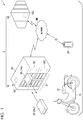
- Fig. 1 is a view illustrating an overall configuration of a battery-sharing service system 1 (a battery deterioration suppression storage system and a charging system) in an embodiment.
- the battery-sharing service system 1 includes a straddle-type motorcycle 12 (straddle-type vehicle) which is a moving body, a detachable battery 14 (battery), a battery deterioration-suppressing storage device 2, and a mobile terminal 28.
- the battery deterioration-suppressing storage device 2 includes a charging station 16 (battery deterioration-suppressing storage device, charging device) and a management server 18 (server device).
- the moving body includes a vehicle in addition to the motorcycle 12 illustrated in Fig. 1 .
- An example of a moving body that is not a vehicle may be, for example, a portable charging/power-supply device carried by a person or a vehicle described in Japanese Unexamined Patent Application, First Publication No. 2019-068552 .
- the moving body may be mobile robots, autonomous traveling devices, electric bicycles, autonomous traveling vehicles, other electric vehicles, drone flight vehicles, or other electric moving devices (electric mobility).
- the motorcycle 12 as an example of the moving body will be described in detail.
- the battery-sharing service system 1 is a system that provides a sharing service in which a plurality of users share the detachable battery 14 serving as a drive source of the motorcycle 12.
- the motorcycle 12 is an electric vehicle EV that travels due to electric power supplied from the detachable battery 14.
- the straddle-type motorcycle 12 will be described as an example of the electric vehicle, but the electric vehicle may be electric bicycles, four-wheeled automatic vehicles, or the like.
- the detachable battery 14 is a cassette-type electricity storage device that is detachably attached to the motorcycle 12 capable of traveling due to at least electric power.
- the detachable battery 14 may be distinguished such that the detachable battery 14 that needs to be charged is a "used battery 14u,” and the detachable battery 14 in which charging has been completed is a “charged battery 14c.”
- At least one detachable battery 14 is mounted on one motorcycle 12. A configuration of the detachable battery 14 will be described later.
- the charging station 16 is a facility for storing and charging one or more detachable batteries 14 and is installed at a plurality of places.
- a slot part 21 constituted by a plurality (12 in the example of Fig. 1 ) of slots, a display 161, and an authenticator 162 are provided in a housing 20 of the charging station 16.
- the charging station 16 is connected to be able to communicate with the management server 18 via a network NW
- the network NW is a wireless communication network or a wired communication network.
- a charger 163 capable of charging the detachable battery 14 and a connection part 164 ( Fig. 3 ) are provided on a back side of the slot part 21.
- the charging station 16 transmits lending date/time information indicating a date and time when the battery was lent and a station ID which is identification information of the charging station 16 to the management server 18.
- the lending date/time information includes a date, a time, and a day of the week of the lending.
- the charging station 16 receives information indicating the number of detachable batteries 14 (number of batteries for use) to be prepared for each time period.
- the charging station 16 actively controls a state of charge (SOC) of each detachable battery 14 stored in the charging station 16 on the basis of the received number of batteries for use. Control of the SOC will be described later.
- SOC state of charge
- the management server 18 receives the lending date/time information and the station ID transmitted from the charging station 16.
- the management server 18 acquires local weather information at the lending date and time from, for example, the Internet via the network NW on the basis of the lending date/time information and the station ID.
- the weather information includes weather type (sunny, cloudy, rainy, snow, typhoon, or the like), and may also include information on temperature and humidity, pollen information, or the like.
- the management server 18 obtains an expected value of the number of detachable batteries 14 to be used for replacement for each time period for each day of the week and weather type.
- the management server 18 transmits the number of batteries for use, which is the number of batteries to be prepared according to the obtained expected value, to the charging station 16 via the network NW
- the management server 18 is connected to be able to communicate with the charging station 16 and the mobile terminal 28 via the network NW
- the mobile terminal 28 is a terminal carried by a user, and may be, for example, a smartphone, a tablet terminal, a laptop computer, or the like.
- the user operates the mobile terminal 28 to select and reserve one of the charging stations 16 capable of lending the detachable battery 14.
- the mobile terminal 28 transmits the operated result to the management server 18.
- the mobile terminal 28 receives point information transmitted from the management server 18 and displays the received point information on a display unit 2801.
- Fig. 2 is a diagram showing a configuration example of the detachable battery 14 according to the present embodiment.
- the detachable battery 14 includes a power storage unit 141, a measurement sensor 142, a battery management unit (BMU) 143, a storage unit 144, and a connection part 145.
- BMU battery management unit
- the power storage unit 141 may be, for example, any one of a secondary battery, a lead storage battery, a capacitor, a lithium ion battery, and the like.
- the measurement sensor 142 is constituted by various sensors that measure a current or a temperature.
- the measurement sensor 142 outputs measured values to the BMU 143.
- the temperature sensor measures a temperature of the power storage unit 141.
- the current sensor measures a value of a current flowing through the power storage unit 141.
- the BMU 143 is a battery management unit (battery management unit), and controls charging and power supply to the power storage unit 141.
- the BMU 143 may store, for example, a state of charge (SOC; remaining capacity) of the detachable battery 14 in the storage unit 144.
- SOC state of charge
- the storage unit 144 may store for example, identification information of the detachable battery 14, the SOC of the detachable battery 14, or the like.
- the storage unit 144 stores a program that causes the BMU 143 to execute processing.
- connection part 145 is a connection part to the slot part 21 of the charging station 16 and has a communication function.
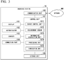
- Fig. 3 is a diagram showing a configuration example of the charging station 16 according to the present embodiment.
- the charging station 16 includes the display 161, the authenticator 162, the charger 163 (charging unit), the connection part 164, a communication unit 165, a storage unit 166, and a control unit 167 (acquisition unit).
- the control unit 167 includes a charge control unit 1671, a measurement sensor 1672, an information acquisition unit 1673, a processing unit 1674, and a timekeeping unit 1675.
- the charging station 16 receives electric power from a power grid (not shown).
- the display 161 is any one of a liquid crystal display device, an organic electro luminescence (EL) display device, an electronic ink display device, and the like.
- the display 161 displays information output from the control unit 167. Displayed information may be, for example, a remaining capacity, a usage fee, or the like of the detachable battery 14.
- the authenticator 162 is a device that reads recorded information of a near-field communication (NFC) card (not shown) carried by the user using, for example, NFC. Thereby, the charging station 16 reads a user ID included in the recorded information. The authenticator 162 outputs the acquired user ID to the control unit 167 and authenticates a user who has a right to use the sharing service on the basis of an authentication result output from the communication unit 165.
- NFC near-field communication
- the charger 163 is a device that charges the detachable battery 14 under control of the control unit 167 in a state in which the connection part 145 of the detachable battery 14 and the connection part 164 of the charging station 16 are connected.
- a power source (not shown) for supplying electric power to the detachable battery 14 is connected to the charger 163.
- the connection part 164 is a connection part to the detachable battery 14 and performs supply of electric power.
- the connection part 164 acquires battery information on the battery stored in the storage unit 144 of the detachable battery 14, and outputs the acquired battery information to the information acquisition unit 1673.
- the connection part 164 outputs lending information indicating that the detachable battery 14 has been lent to the information acquisition unit 1673 when the detachable battery 14 is removed.
- the communication unit 165 transmits the lending date/time information and the station ID output from the control unit 167 to the management server 18 via the network NW.
- the communication unit 165 receives information indicating the number of detachable batteries 14 prepared for each time period (the number of batteries for each time period) and outputs the received number of batteries for use for each time period to the processing unit 1674.
- the communication unit 165 receives reservation information of the detachable battery 14 transmitted from the management server 18, and outputs the received reservation information of the detachable battery 14 to the control unit 167.
- the communication unit 165 receives an authentication result of authentication performed by the management server 18 and outputs the received authentication result to the authenticator 162.
- the storage unit 166 stores the station ID, which is the identification information of the charging station 16, and stores battery information or the like when the detachable battery 14 is returned.
- the storage unit 166 stores the number of batteries for use for each time period.
- the storage unit 166 stores a program that causes the control unit 167 to execute processing.
- the control unit 167 acquires the lending information output from the connection part 164 and outputs the lending date/time information and the station ID at the time of acquiring the lending information to the communication unit 165.
- the control unit 167 actively controls the SOC of the detachable battery 14 on the basis of the number of batteries for use for each time period output from the communication unit 165.
- the control unit 167 permits the user to rent the detachable battery 14.
- the control unit 167 functions as the charge control unit 1671, the information acquisition unit 1673, the processing unit 1674, and the timekeeping unit 1675 by reading and executing the program stored in the storage unit 166.
- the charge control unit 1671 controls the charger 163 to control charging of the detachable battery 14 inserted in the slot part 21 on the basis of the battery information output from the information acquisition unit 1673 and a measured value of the measurement sensor 1672.
- the measurement sensor 1672 may be, for example, a current sensor or a voltage sensor.
- the measurement sensor 1672 measures a current value flowing through the detachable battery 14 and a voltage value thereof and outputs the measured measurement values to the charge control unit 1671.
- the information acquisition unit 1673 acquires the battery information output by the detachable battery 14 connected to the connection part 164 and outputs the acquired battery information to the charge control unit 1671.
- the processing unit 1674 When the processing unit 1674 acquires the lending information output from the connection part 164, the processing unit 1674 uses a present date and time generated by the timekeeping unit 1675 as the lending date/time information and outputs the lending date/time information and the station ID stored in the storage unit 166 to the communication unit 165.
- the processing unit 1674 stores the number of batteries for use for each time period output from the communication unit 165 in the storage unit 166.
- the processing unit 1674 actively controls the SOC of the detachable battery 14 by controlling whether to charge the detachable battery 14 on the basis of the number of batteries for use for each time period stored in the storage unit 166.
- the timekeeping unit 1675 includes an oscillation circuit and a frequency-dividing circuit.
- the timekeeping unit 1675 generates a present date and time by timing using a reference clock generated by the oscillation circuit and the frequency-dividing circuit on the basis of, for example, the date and time information acquired from the network NW
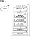
- Fig. 4 is a diagram showing a configuration example of the management server 18 according to the present embodiment.
- the management server 18 includes a communication unit 181, a storage unit 182, a control unit 183 (acquisition unit), and an output unit 184.
- the control unit 183 includes an information acquisition unit 1831, an expected value calculation unit 1832, and a use number estimation unit 1833.
- the communication unit 181 receives the lending date/time information and the station ID transmitted from the charging station 16 via the network NW and outputs the received lending date/time information and the station ID to the control unit 183.
- the communication unit 181 transmits the number of batteries for use for each time period output from the control unit 183 to the charging station 16 via the network NW
- the storage unit 182 stores an expected value of the number of replacement batteries for each time period for each day of the week and weather type.
- the storage unit 182 stores the station ID in association with information indicating a location of the charging station 16 (address, town name, latitude and longitude, or the like).
- the storage unit 182 stores a program that causes the control unit 183 to execute processing.
- the information acquisition unit 1831 acquires the lending date/time information and the station ID output from the communication unit 181.
- the information acquisition unit 1831 acquires weather information at the lending date and time via the communication unit 181 on the basis of the location information stored in the storage unit 182 in association with the station ID.
- the information acquisition unit 1831 outputs the acquired weather information, lending date/time information, and station ID to the expected value calculation unit 1832.
- the expected value calculation unit 1832 acquires the weather information, the lending date/time information, and the station ID output from the information acquisition unit 1831.
- the expected value calculation unit 1832 calculates an expected value of the number of replacement batteries for each time period for each day of the week and weather type and for each station using the acquired weather information and lending date/time information.
- the expected value calculation unit 1832 stores the calculated expected value of the number of replacement batteries for each time period for each day of the week and weather type in the storage unit 182.
- the use number estimation unit 1833 estimates the number of detachable batteries 14 prepared for each time period for each day of the week and weather type and for each station according to the expected value stored in the storage unit 182.
- the use number estimation unit 1833 outputs information indicating the expected number of detachable batteries 14 prepared for each time period for each day of the week and weather type (information on the number of batteries for use for each time period) to the communication unit 181.
- the use number estimation unit 1833 may output the information indicating the expected number of detachable batteries 14 prepared for each time period for each day of the week and weather type (information on the number of batteries for use for each time period) to the output unit 184.
- the output unit 184 is an image display device, a printing device, or the like. For each station output by the use number estimation unit 1833, the output unit 184 displays or prints the number of detachable batteries 14 prepared for each time period for each day of the week and weather type (the number of batteries for use for each time period).
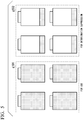
- Fig. 5 is a view illustrating a state example of the detachable batteries 14 stored in the charging station 16 according to the present embodiment.
- Fig. 5 illustrates an example in which a total number of detachable batteries 14 stored in the charging station 16 is eight.
- the number for use received from the management server 18 is four. Therefore, the charging station 16 stores four fully charged detachable batteries 14 for use as denoted by reference sign g101 and the remaining four detachable batteries 14 for deterioration suppression as denoted by reference sign g102.
- the detachable battery 14 for deterioration suppression is in a returned state and a low SOC state.
- Fig. 6 is a diagram showing an expected value and the number of batteries for use according to the present embodiment.
- reference sign gill indicates an expected value
- reference sign g112 indicates the number of batteries for use.
- the horizontal axis represents time (hour)
- the vertical axis represents an expected value (piece) of the number of batteries for use.
- the horizontal axis represents time (hour)
- the vertical axis represents the number (piece) of batteries for use.
- Fig. 6 shows an expected value and the number of batteries for use in a case of a predetermined day of the week and weather type. In the following, the expected value and the number of batteries for use when the weather is sunny will be described.
- an expected value from 0:00 to 1:00 is three
- an expected value from 1:00 to 2:00 is two
- an expected value from 2:00 to 3:00 is zero, and so on.
- the expected value calculation unit 1832 calculates the expected value of the number of batteries for use for each time period on the basis of the lending date/time information received when the weather is sunny.
- the expected value calculation unit 1832 may obtain, for example, an average value of the detachable battery 14 lent from 0:00 to 1:00 on a sunny day and calculate the obtained average value as the expected value.
- the number of batteries for use from 0:00 to 6:00 is two
- the number of batteries for use from 6:00 to 19:00 is six
- the number of batteries for use from 19:00 to 24:00 is four.
- the use number estimation unit 1833 may estimate the number of batteries for use from 0:00 to 7:00 by obtaining an average value of, for example, an expected value from 0:00 to 1:00, an expected value from 1:00 to 2:00, an expected value from 2:00 to 3:00, an expected value from 4:00 to 5:00, and an expected value from 5:00 to 6:00, and an expected value from 6:00 to 7:00.
- the use number estimation unit 1833 may estimate a maximum value of expected values in a time period being obtained as the number of batteries for use.
- Fig. 7 is a diagram showing an example of expected values stored in the storage unit 182 of the management server 18 according to the present embodiment.
- the example shown in Fig. 7 is an example in which the storage unit 182 stores expected values of the number of batteries for each time period of every hour for each day of the week and each weather type.
- the storage unit 182 may store an expected value (two) of the batteries in association with a time period from 0:00 to 1:00 on Monday and sunny weather.
- the example shown in Fig. 7 is an example, and the storage unit 182 stores an expected value of the number of batteries for each time period in association with at least one of a day of the week and weather type.
- Fig. 8 is a diagram showing an example of the number of batteries for use stored in the storage unit 182 of the management server 18 according to the present embodiment.
- the storage unit 182 stores the number of batteries for use for time periods of daytime and midnight in association with each day of the week and each weather type.
- the storage unit 182 may store the number of batteries for use (six) in association with a time period of daytime on Monday and sunny weather.
- the example shown in Fig. 8 is an example, and the storage unit 182 stores the number of batteries for use for each time period in association with at least one of a day of the week and weather type.
- Fig. 9 is a flowchart of preparation processing performed by the charging station 16 and the management server 18 according to the present embodiment.
- Step L1 A user visits the charging station 16 and starts replacement work of the detachable battery 14.
- Step S1 After the user returns the detachable battery 14, the control unit 167 of the charging station 16 lends the charged detachable battery 14 to the user.
- Step S2 The control unit 167 of the charging station 16 transmits lending date/time information, which is a date and time at the time of the lending, and a station ID to the management server 18 using the communication unit 165.
- Step S3 The control unit 183 of the management server 18 receives the lending date/time information and the station ID transmitted from the charging station 16 and stores the received lending date/time information and station ID in the storage unit 182. Next, the control unit 183 acquires local weather information at the time of the lent date and time from the Internet or the like by the communication unit 181 via the network NW on the basis of the lending date/time information and the station ID.
- Step S4 The expected value calculation unit 1832 of the management server 18 calculates an expected value of the number of replacement batteries for each time period for each day of the week and weather type on the basis of the lending date/time information received from the charging station 16 and the acquired weather information and then stores the calculated expected value in the storage unit 182.
- Step S5 The use number estimation unit 1833 of the management server 18 estimates the number of batteries (number of batteries for use) to be prepared for each time period for each day of the week and weather type according to the expected value of the number of replacement batteries for each time period for each day of the week and weather type stored in the storage unit 182.
- Step S6 The use number estimation unit 1833 of the management server 18 transmits the number of batteries (number of batteries for use) to be prepared for each estimated time period to the charging station 16 by the communication unit 181.
- Step L2 The replacement work of the detachable battery 14 ends.
- the charging station 16 transmits the lending date/time information and the station ID during the replacement work of the detachable battery 14, and the management server 18 calculates the expected value and estimates the number of batteries to be prepared for each time period, but the present invention is not limited thereto.
- the charging station 16 may transmit the lending date/time information and the station ID, for example, at a predetermined time, or may transmit the lending date/time information and the station ID when the number of lendings reaches a predetermined number.
- the management server 18 may calculate the expected value and estimate the number of batteries to be prepared for each time period at a predetermined time. For example, the management server 18 may transmit the number of batteries for use for each time period for one day to the charging station 16 once a day at a predetermined time.
- Fig. 10 is a flowchart of the charging determination processing performed by the charging station 16 according to the present embodiment.
- Step S11 When the detachable battery 14 is connected to the connection part 164, the control unit 167 of the charging station 16 determines that the detachable battery 14 has been returned.
- Step S12 The control unit 167 reads the number of batteries for use in a time period corresponding to the returned time from the storage unit 166. Next, the control unit 167 determines whether or not the number of fully charged batteries in the charging station is larger than the number of batteries for use. When the control unit 167 determines that the number of fully charged batteries in the charging station is larger than the number of batteries for use (step S12; YES), the control unit 167 proceeds to processing of step S13. When the control unit 167 determines that the number of fully charged batteries in the charging station is not larger than the number of batteries for use (step S12; NO), the control unit 167 proceeds to processing of step S14.
- Step S13 The control unit 167 does not perform charging of the returned detachable battery 14.
- the control unit 167 ends the processing.
- Step S14 The control unit 167 performs charging of the returned detachable battery 14. That is, the control unit 167 determines the number of batteries to be charged among the plurality of batteries on the basis of the number of batteries for use and charges a determined number of batteries. Alternatively, the control unit 167 may determine the number of batteries that are not charged among the plurality of batteries on the basis of the number of batteries for use. The control unit 167 ends the processing.
- the control unit 167 performs the processing of steps S12, S13, and S14 every predetermined time (for example, 10 minutes). Therefore, when the fully charged batteries for use are used, the control unit 167 also performs charging of the batteries for deterioration suppression.
- a timing for performing the processing may also be when a battery is lent or when a battery has been lent.
- the control can be performed in accordance with timing of use by the user by controlling at least one of the number of batteries to be charged and the number of batteries not to be charged for the plurality of detachable batteries 14 in at least one of timings when the detachable battery 14 is lent or has been lent from the charging station 16 and when the detachable battery 14 is returned to the charging station 16.
- control unit 167 performs charging of two of them and does not perform charging of the remaining two.
- the management server 18 may transmit the number of batteries for deterioration suppression stored in a low SOC state without being charged to the charging station 16.
- the management server 18 may transmit proportions of the number of batteries for use and the number of batteries for deterioration suppression to the charging station 16.
- the management server 18 may estimate the number of batteries for use for a plurality of charging stations 16 included in a predetermined range.
- the charging station 16 may acquire weather information from the Internet via the network NW and the weather information may be added to the lending date/time information and the station ID to be transmitted to the management server 18.
- the management server 18 controls the SOC of the detachable battery 14 so that deterioration suppression is possible on the basis of a date and time when the detachable battery 14 is lent and weather type at the lent location, that is, on the basis of usage information of the detachable battery 14 of the user. That is, the management server 18 determines proportions of the battery for use and the battery for deterioration suppression from usage state data of the user. Then, the charging station 16 prepares fully charged batteries for use and stores batteries other than the fully charged batteries for use in a low SOC state for deterioration suppression according to the control of the management server 18. Then, when the batteries for use are used, the charging station 16 also charges the batteries for deterioration suppression.
- the SOC for optimum storage can also be adjusted according to the usage state of the user. Also, according to the present embodiment, deterioration of the battery is suppressed and the battery can be used for a long period of time compared to a case in which charging is started at the moment when the battery is loaded in the charging station 16.
- management server 18 performs calculation of the expected value and estimation of the number of batteries for use has been described in the above-described example, but processing for these may be performed by the charging station 16.
- One embodiment of the present invention is a battery deterioration-suppressing storage device 2 including a detachable battery 14 detachably attached to a motorcycle 12 that is movable utilizing electric power, and a control unit 167 controlling at least one of the number of batteries to be charged and the number of batteries not to be charged for a plurality of detachable batteries 14 on the basis of a state in which the detachable battery 14 has been used by a user.
- a battery-sharing service system 1 including a detachable battery 14 detachably attached to a motorcycle 12 that is movable utilizing electric power, a charging station 16 performing charging of the detachable battery 14 and configured to transmit lending date/time information indicating a date and time when the detachable battery 14 was lent to a management server 18 and control at least one of the number of batteries to be charged and the number of batteries not to be charged for a plurality of detachable batteries 14 on the basis of received control information from the management server 18, and the management server 18 generating the control information that controls at least one of the number of batteries to be charged and the number of batteries not to be charged for the plurality of detachable batteries 14 on the basis of the lending date/time information received from the charging station 16 and configured to transmit the generated control information to the charging station 16.
- Some or all of the processing performed by the battery deterioration-suppressing storage device 2 may be performed by recording a program for realizing all or part of the functions of the battery deterioration-suppressing storage device 2 of the present invention on a computer-readable recording medium and causing a computer system to read and execute the program recorded on the recording medium.
- the "computer system” mentioned herein is configured to include an operating system (OS) or hardware such as peripheral devices.
- the “computer system” is configured to also include a WWW system in which a homepage-providing environment (or display environment) is provided.
- the "computer-readable recording medium” refers to a portable medium such as a flexible disk, a magneto-optical disk, a read-only memory (ROM), or a compact disc read-only memory (CD-ROM), and a storage device such as a hard disk incorporated in a computer system. Further, the "computer-readable recording medium” is configured to also include a medium that holds a program for a certain period of time such as a volatile memory (random-access memory (RAM)) in a computer system serving as a server or a client when a program is transmitted via a network such as the Internet or a communication link such as a telephone circuit.
- RAM random-access memory
- the above-described program may be transmitted to other computer systems from the computer system storing the program in a storage device or the like via a transmission medium or by transmission waves in the transmission medium.
- the "transmission medium” for transmitting the program refers to a medium having a function of transmitting information, such as a network (communication network) like the Internet or a communication link (communication line) like a telephone circuit.
- the above-described program may be a program for realizing some of the above-described functions.
- the program may be a so-called differential file (differential program) which realizes the above-described functions in combination with a program already recorded on the computer system.
Landscapes
- Engineering & Computer Science (AREA)
- Power Engineering (AREA)
- Transportation (AREA)
- Mechanical Engineering (AREA)
- Chemical Kinetics & Catalysis (AREA)
- Chemical & Material Sciences (AREA)
- Electrochemistry (AREA)
- General Chemical & Material Sciences (AREA)
- Manufacturing & Machinery (AREA)
- Aviation & Aerospace Engineering (AREA)
- Life Sciences & Earth Sciences (AREA)
- Sustainable Development (AREA)
- Sustainable Energy (AREA)
- Charge And Discharge Circuits For Batteries Or The Like (AREA)
- Cold Air Circulating Systems And Constructional Details In Refrigerators (AREA)
Abstract
Description
- The present invention relates to a charging system, a charging device, a charging method, and a program.
- Priority is claimed on Japanese Patent Application No.
2018-143634, filed on July 31, 2018 - A sharing service in which a battery (battery) serving as a drive source of an electric vehicle is configured as a detachable-type and shared by a plurality of users is known. In this service, a charging station for storing and charging one or more detachable batteries is installed, and a mechanism for charging a user who uses the charging station is established.
- For example,
Patent Document 1 describes a collection/charging/distribution device that collects, charges, and distributes portable electric energy storage devices when the portable electric energy storage devices (detachable batteries) are used and electric power thereof has been consumed. Therefore, in the technology described inPatent Document 1, the collection/charging/distribution devices each have a plurality of containers that detachably accommodate the portable electric energy storage devices for collecting, charging, and distributing. - In such a battery-sharing service, a user takes out a detachable battery that needs to be charged from an electric vehicle and returns the detachable battery to the collection/charging/distribution device. At this time, the user takes out a charged detachable battery from the collection/charging/distribution device and attaches the charged detachable battery to the electric vehicle. In this case, charged detachable batteries are waiting in the collection/charging/distribution device in preparation for replacement with the detachable batteries of users.
- For example,
Patent Document 2 discloses a portable charging/power-supply device including a battery and a charging/power-supply unit in which a housing chamber capable of accommodating the battery is formed as an example of a mobile body into which a battery can be detachably loaded. - Published Japanese Translation No.
2014-527689 - Japanese Unexamined Patent Application, First Publication No.
2019-068552 - However, a capacity of a battery (battery) deteriorates according to the conditions of use and environmental conditions when the battery is stored. For example, a battery generally has a high state of charge (SOC; remaining capacity) and deteriorates in a short period of time. In the technology described in
Patent Document 1, since an SOC of the battery in the electric vehicle depends on usage of the user, it is not possible to actively perform a control. - An aspect of the present invention is to provide a charging system, a charging device, a charging method, and a program in which an SOC of a battery can be actively controlled.
-
- (1) A charging system according to one aspect of the present invention includes: a battery which is detachably attached to a moving body which is movable utilizing electric power; a charging device which charges a plurality of batteries; and an acquisition unit which acquires a number of batteries to be charged and/or a number of batteries not to be charged among the plurality of batteries based on battery usage information indicating a usage state of the batteries of a user.
- (2) In the charging system described above, the acquisition unit may calculate an expected value of the number of batteries used for each time period based on the battery usage information and acquire the number of batteries to be charged and/or the number of batteries not to be charged among the plurality of batteries based on the calculated expected value.
- (3) In the charging system described above, the acquisition unit may calculate an expected value of the number of batteries used for each day of the week and for each time period based on the battery usage information and acquire the number of batteries to be charged and/or the number of batteries not to be charged among the plurality of batteries based on the calculated expected value.
- (4) In the charging system described above, the acquisition unit may calculate an expected value of the number of batteries used for each weather type and for each time period based on the battery usage information and acquire the number of batteries to be charged and/or the number of batteries not to be charged among the plurality of batteries based on the calculated expected value.
- (5) In the charging system described above, the acquisition unit may acquire the number of batteries to be charged and/or the number of batteries not to be charged among the plurality of batteries when the battery is lent from the charging device or when the battery is returned to the charging device.
- (6) In the charging system described above, the battery usage information may be lending date/time information indicating a date and time when the battery is lent.
- (7) A charging device according to another aspect of the present invention includes: a charging unit which charges a plurality of batteries detachably attached to a moving body which is movable utilizing electric power; and an acquisition unit which acquires a number of batteries to be charged and/or a number of batteries not to be charged among the plurality of batteries based on battery usage information indicating a usage state of the batteries of a user.
- (8) A charging method according to yet another aspect of the present invention includes: a step of charging a plurality of batteries detachably attached to a moving body which is movable utilizing electric power; and a step of acquiring a number of batteries to be charged and/or a number of batteries not to be charged among the plurality of batteries based on battery usage information indicating a usage state of the batteries of a user.
- (9) Still another aspect of the present invention is a program which causes a computer to execute a step of charging a plurality of batteries detachably attached to a moving body which is movable utilizing electric power; and a step of acquiring a number of batteries to be charged and/or a number of batteries not to be charged among the plurality of batteries based on battery usage information indicating a usage state of the batteries of a user.
- (10) Yet still another aspect of the present invention is a computer-readable storage medium including the above-described program.
- According to the above-described (1), and (6) to (10), since the number of batteries to be charged and/or the number of batteries not to be charged among the plurality of batteries are acquired on the basis of the state in which the battery has been used by the user, the SOC of the battery can be actively controlled.
- According to (2) described above, the number of batteries used for each time period can be obtained with high accuracy using the expected value calculated for each time period.
- According to (3) described above, the number of batteries to be charged and/or the number of batteries not to be charged among the plurality of batteries for each day of the week and for each time period can be acquired.
- According to (4) described above, the number of batteries to be charged and/or the number of batteries not to be charged among the plurality of batteries for each weather type and for each time period can be acquired.
- According to (5) described above, by acquiring the number of batteries to be charged and/or the number of batteries not to be charged among the plurality of batteries when a battery is lent from the charging device or when a battery is returned to the charging device, the number thereof can be acquired in accordance with a timing of use by the user.
-
-
Fig. 1 is a view illustrating an overall configuration of a battery-sharing service system in an embodiment. -
Fig. 2 is a diagram showing a configuration example of a detachable battery according to the embodiment. -
Fig. 3 is a diagram showing a configuration example of a charging station according to the embodiment. -
Fig. 4 is a diagram showing a configuration example of a management server according to the embodiment. -
Fig. 5 is a view illustrating a state example of detachable batteries stored in the charging station according to the embodiment. -
Fig. 6 is a diagram showing an expected value and the number of batteries for use according to the embodiment. -
Fig. 7 is a diagram showing an example of expected values stored in a storage unit of the management server according to the embodiment. -
Fig. 8 is a diagram showing an example of the number of batteries for use stored in the storage unit of the management server according to the embodiment. -
Fig. 9 is a flowchart of preparation processing performed by the charging station and the management server according to the embodiment. -
Fig. 10 is a flowchart of charging determination processing performed by the charging station according to the embodiment. - Hereinafter, embodiments of the present invention will be described with reference to the drawings. In the drawings used in the following description, scales of each member will be appropriately changed so that a size of each member is recognizable.
-
Fig. 1 is a view illustrating an overall configuration of a battery-sharing service system 1 (a battery deterioration suppression storage system and a charging system) in an embodiment. - As illustrated in
Fig. 1 , the battery-sharing service system 1 includes a straddle-type motorcycle 12 (straddle-type vehicle) which is a moving body, a detachable battery 14 (battery), a battery deterioration-suppressingstorage device 2, and amobile terminal 28. The battery deterioration-suppressingstorage device 2 includes a charging station 16 (battery deterioration-suppressing storage device, charging device) and a management server 18 (server device). - The moving body includes a vehicle in addition to the
motorcycle 12 illustrated inFig. 1 . An example of a moving body that is not a vehicle may be, for example, a portable charging/power-supply device carried by a person or a vehicle described in Japanese Unexamined Patent Application, First Publication No.2019-068552 motorcycle 12 as an example of the moving body will be described in detail. - The battery-
sharing service system 1 is a system that provides a sharing service in which a plurality of users share thedetachable battery 14 serving as a drive source of themotorcycle 12. Themotorcycle 12 is an electric vehicle EV that travels due to electric power supplied from thedetachable battery 14. In the embodiment, the straddle-type motorcycle 12 will be described as an example of the electric vehicle, but the electric vehicle may be electric bicycles, four-wheeled automatic vehicles, or the like. - The
detachable battery 14 is a cassette-type electricity storage device that is detachably attached to themotorcycle 12 capable of traveling due to at least electric power. Hereinafter, for convenience of explanation, thedetachable battery 14 may be distinguished such that thedetachable battery 14 that needs to be charged is a "usedbattery 14u," and thedetachable battery 14 in which charging has been completed is a "chargedbattery 14c." At least onedetachable battery 14 is mounted on onemotorcycle 12. A configuration of thedetachable battery 14 will be described later. - The charging
station 16 is a facility for storing and charging one or moredetachable batteries 14 and is installed at a plurality of places. Aslot part 21 constituted by a plurality (12 in the example ofFig. 1 ) of slots, adisplay 161, and anauthenticator 162 are provided in ahousing 20 of the chargingstation 16. The chargingstation 16 is connected to be able to communicate with themanagement server 18 via a network NW The network NW is a wireless communication network or a wired communication network. A charger 163 (Fig. 3 ) capable of charging thedetachable battery 14 and a connection part 164 (Fig. 3 ) are provided on a back side of theslot part 21. When thedetachable battery 14 is lent, the chargingstation 16 transmits lending date/time information indicating a date and time when the battery was lent and a station ID which is identification information of the chargingstation 16 to themanagement server 18. The lending date/time information includes a date, a time, and a day of the week of the lending. The chargingstation 16 receives information indicating the number of detachable batteries 14 (number of batteries for use) to be prepared for each time period. The chargingstation 16 actively controls a state of charge (SOC) of eachdetachable battery 14 stored in the chargingstation 16 on the basis of the received number of batteries for use. Control of the SOC will be described later. - The
management server 18 receives the lending date/time information and the station ID transmitted from the chargingstation 16. Themanagement server 18 acquires local weather information at the lending date and time from, for example, the Internet via the network NW on the basis of the lending date/time information and the station ID. The weather information includes weather type (sunny, cloudy, rainy, snow, typhoon, or the like), and may also include information on temperature and humidity, pollen information, or the like. On the basis of the received information and the acquired weather information, themanagement server 18 obtains an expected value of the number ofdetachable batteries 14 to be used for replacement for each time period for each day of the week and weather type. Themanagement server 18 transmits the number of batteries for use, which is the number of batteries to be prepared according to the obtained expected value, to the chargingstation 16 via the network NW Themanagement server 18 is connected to be able to communicate with the chargingstation 16 and themobile terminal 28 via the network NW - The
mobile terminal 28 is a terminal carried by a user, and may be, for example, a smartphone, a tablet terminal, a laptop computer, or the like. The user operates themobile terminal 28 to select and reserve one of the chargingstations 16 capable of lending thedetachable battery 14. Themobile terminal 28 transmits the operated result to themanagement server 18. Themobile terminal 28 receives point information transmitted from themanagement server 18 and displays the received point information on a display unit 2801. - Next, a configuration example of the
detachable battery 14 will be described. -
Fig. 2 is a diagram showing a configuration example of thedetachable battery 14 according to the present embodiment. As shown inFig. 2 , thedetachable battery 14 includes apower storage unit 141, ameasurement sensor 142, a battery management unit (BMU) 143, astorage unit 144, and aconnection part 145. - The
power storage unit 141 may be, for example, any one of a secondary battery, a lead storage battery, a capacitor, a lithium ion battery, and the like. - The
measurement sensor 142 is constituted by various sensors that measure a current or a temperature. Themeasurement sensor 142 outputs measured values to theBMU 143. The temperature sensor measures a temperature of thepower storage unit 141. The current sensor measures a value of a current flowing through thepower storage unit 141. - The
BMU 143 is a battery management unit (battery management unit), and controls charging and power supply to thepower storage unit 141. TheBMU 143 may store, for example, a state of charge (SOC; remaining capacity) of thedetachable battery 14 in thestorage unit 144. - The
storage unit 144 may store for example, identification information of thedetachable battery 14, the SOC of thedetachable battery 14, or the like. Thestorage unit 144 stores a program that causes theBMU 143 to execute processing. - The
connection part 145 is a connection part to theslot part 21 of the chargingstation 16 and has a communication function. - Next, a configuration example of the charging
station 16 will be described. -
Fig. 3 is a diagram showing a configuration example of the chargingstation 16 according to the present embodiment. As shown inFig. 3 , the chargingstation 16 includes thedisplay 161, theauthenticator 162, the charger 163 (charging unit), theconnection part 164, acommunication unit 165, astorage unit 166, and a control unit 167 (acquisition unit). - The
control unit 167 includes acharge control unit 1671, ameasurement sensor 1672, aninformation acquisition unit 1673, aprocessing unit 1674, and atimekeeping unit 1675. - The charging
station 16 receives electric power from a power grid (not shown). - The
display 161 is any one of a liquid crystal display device, an organic electro luminescence (EL) display device, an electronic ink display device, and the like. Thedisplay 161 displays information output from thecontrol unit 167. Displayed information may be, for example, a remaining capacity, a usage fee, or the like of thedetachable battery 14. - The
authenticator 162 is a device that reads recorded information of a near-field communication (NFC) card (not shown) carried by the user using, for example, NFC. Thereby, the chargingstation 16 reads a user ID included in the recorded information. Theauthenticator 162 outputs the acquired user ID to thecontrol unit 167 and authenticates a user who has a right to use the sharing service on the basis of an authentication result output from thecommunication unit 165. - The
charger 163 is a device that charges thedetachable battery 14 under control of thecontrol unit 167 in a state in which theconnection part 145 of thedetachable battery 14 and theconnection part 164 of the chargingstation 16 are connected. A power source (not shown) for supplying electric power to thedetachable battery 14 is connected to thecharger 163. - The
connection part 164 is a connection part to thedetachable battery 14 and performs supply of electric power. Theconnection part 164 acquires battery information on the battery stored in thestorage unit 144 of thedetachable battery 14, and outputs the acquired battery information to theinformation acquisition unit 1673. Theconnection part 164 outputs lending information indicating that thedetachable battery 14 has been lent to theinformation acquisition unit 1673 when thedetachable battery 14 is removed. - The
communication unit 165 transmits the lending date/time information and the station ID output from thecontrol unit 167 to themanagement server 18 via the network NW. Thecommunication unit 165 receives information indicating the number ofdetachable batteries 14 prepared for each time period (the number of batteries for each time period) and outputs the received number of batteries for use for each time period to theprocessing unit 1674. Thecommunication unit 165 receives reservation information of thedetachable battery 14 transmitted from themanagement server 18, and outputs the received reservation information of thedetachable battery 14 to thecontrol unit 167. Thecommunication unit 165 receives an authentication result of authentication performed by themanagement server 18 and outputs the received authentication result to theauthenticator 162. - The
storage unit 166 stores the station ID, which is the identification information of the chargingstation 16, and stores battery information or the like when thedetachable battery 14 is returned. Thestorage unit 166 stores the number of batteries for use for each time period. Thestorage unit 166 stores a program that causes thecontrol unit 167 to execute processing. - The
control unit 167 acquires the lending information output from theconnection part 164 and outputs the lending date/time information and the station ID at the time of acquiring the lending information to thecommunication unit 165. When thedetachable battery 14 is returned, thecontrol unit 167 actively controls the SOC of thedetachable battery 14 on the basis of the number of batteries for use for each time period output from thecommunication unit 165. When a user is successfully authenticated by theauthenticator 162 thecontrol unit 167 permits the user to rent thedetachable battery 14. - The
control unit 167 functions as thecharge control unit 1671, theinformation acquisition unit 1673, theprocessing unit 1674, and thetimekeeping unit 1675 by reading and executing the program stored in thestorage unit 166. - The
charge control unit 1671 controls thecharger 163 to control charging of thedetachable battery 14 inserted in theslot part 21 on the basis of the battery information output from theinformation acquisition unit 1673 and a measured value of themeasurement sensor 1672. - The
measurement sensor 1672 may be, for example, a current sensor or a voltage sensor. Themeasurement sensor 1672 measures a current value flowing through thedetachable battery 14 and a voltage value thereof and outputs the measured measurement values to thecharge control unit 1671. - The
information acquisition unit 1673 acquires the battery information output by thedetachable battery 14 connected to theconnection part 164 and outputs the acquired battery information to thecharge control unit 1671. - When the
processing unit 1674 acquires the lending information output from theconnection part 164, theprocessing unit 1674 uses a present date and time generated by thetimekeeping unit 1675 as the lending date/time information and outputs the lending date/time information and the station ID stored in thestorage unit 166 to thecommunication unit 165. Theprocessing unit 1674 stores the number of batteries for use for each time period output from thecommunication unit 165 in thestorage unit 166. When thedetachable battery 14 is returned, theprocessing unit 1674 actively controls the SOC of thedetachable battery 14 by controlling whether to charge thedetachable battery 14 on the basis of the number of batteries for use for each time period stored in thestorage unit 166. - The
timekeeping unit 1675 includes an oscillation circuit and a frequency-dividing circuit. Thetimekeeping unit 1675 generates a present date and time by timing using a reference clock generated by the oscillation circuit and the frequency-dividing circuit on the basis of, for example, the date and time information acquired from the network NW - Next, a configuration example of the
management server 18 will be described. -
Fig. 4 is a diagram showing a configuration example of themanagement server 18 according to the present embodiment. As shown inFig. 4 , themanagement server 18 includes acommunication unit 181, astorage unit 182, a control unit 183 (acquisition unit), and anoutput unit 184. Thecontrol unit 183 includes aninformation acquisition unit 1831, an expectedvalue calculation unit 1832, and a usenumber estimation unit 1833. - The
communication unit 181 receives the lending date/time information and the station ID transmitted from the chargingstation 16 via the network NW and outputs the received lending date/time information and the station ID to thecontrol unit 183. Thecommunication unit 181 transmits the number of batteries for use for each time period output from thecontrol unit 183 to the chargingstation 16 via the network NW - The
storage unit 182 stores an expected value of the number of replacement batteries for each time period for each day of the week and weather type. Thestorage unit 182 stores the station ID in association with information indicating a location of the charging station 16 (address, town name, latitude and longitude, or the like). Thestorage unit 182 stores a program that causes thecontrol unit 183 to execute processing. - The
information acquisition unit 1831 acquires the lending date/time information and the station ID output from thecommunication unit 181. When theinformation acquisition unit 1831 acquires the lending date/time information and the station ID, theinformation acquisition unit 1831 acquires weather information at the lending date and time via thecommunication unit 181 on the basis of the location information stored in thestorage unit 182 in association with the station ID. Theinformation acquisition unit 1831 outputs the acquired weather information, lending date/time information, and station ID to the expectedvalue calculation unit 1832. - The expected
value calculation unit 1832 acquires the weather information, the lending date/time information, and the station ID output from theinformation acquisition unit 1831. The expectedvalue calculation unit 1832 calculates an expected value of the number of replacement batteries for each time period for each day of the week and weather type and for each station using the acquired weather information and lending date/time information. The expectedvalue calculation unit 1832 stores the calculated expected value of the number of replacement batteries for each time period for each day of the week and weather type in thestorage unit 182. - The use
number estimation unit 1833 estimates the number ofdetachable batteries 14 prepared for each time period for each day of the week and weather type and for each station according to the expected value stored in thestorage unit 182. The usenumber estimation unit 1833 outputs information indicating the expected number ofdetachable batteries 14 prepared for each time period for each day of the week and weather type (information on the number of batteries for use for each time period) to thecommunication unit 181. - The use
number estimation unit 1833 may output the information indicating the expected number ofdetachable batteries 14 prepared for each time period for each day of the week and weather type (information on the number of batteries for use for each time period) to theoutput unit 184. - The
output unit 184 is an image display device, a printing device, or the like. For each station output by the usenumber estimation unit 1833, theoutput unit 184 displays or prints the number ofdetachable batteries 14 prepared for each time period for each day of the week and weather type (the number of batteries for use for each time period). - Next, a state of the
detachable battery 14 stored in the chargingstation 16 will be described. -
Fig. 5 is a view illustrating a state example of thedetachable batteries 14 stored in the chargingstation 16 according to the present embodiment.Fig. 5 illustrates an example in which a total number ofdetachable batteries 14 stored in the chargingstation 16 is eight. - In the example illustrated in
Fig. 5 , the number for use received from themanagement server 18 is four. Therefore, the chargingstation 16 stores four fully chargeddetachable batteries 14 for use as denoted by reference sign g101 and the remaining fourdetachable batteries 14 for deterioration suppression as denoted by reference sign g102. Thedetachable battery 14 for deterioration suppression is in a returned state and a low SOC state. - Next, an expected value and the number of batteries for use will be described.
-
Fig. 6 is a diagram showing an expected value and the number of batteries for use according to the present embodiment. - In
Fig. 6 , reference sign gill indicates an expected value, and reference sign g112 indicates the number of batteries for use. In the diagram indicated by reference sign g111, the horizontal axis represents time (hour), and the vertical axis represents an expected value (piece) of the number of batteries for use. In the diagram indicated by reference sign g112, the horizontal axis represents time (hour), and the vertical axis represents the number (piece) of batteries for use.Fig. 6 shows an expected value and the number of batteries for use in a case of a predetermined day of the week and weather type. In the following, the expected value and the number of batteries for use when the weather is sunny will be described. - In the example of reference sign g111, an expected value from 0:00 to 1:00 is three, an expected value from 1:00 to 2:00 is two, an expected value from 2:00 to 3:00 is zero, and so on.
- The expected
value calculation unit 1832 calculates the expected value of the number of batteries for use for each time period on the basis of the lending date/time information received when the weather is sunny. The expectedvalue calculation unit 1832 may obtain, for example, an average value of thedetachable battery 14 lent from 0:00 to 1:00 on a sunny day and calculate the obtained average value as the expected value. - In the example of reference sign g112, the number of batteries for use from 0:00 to 6:00 is two, the number of batteries for use from 6:00 to 19:00 is six, and the number of batteries for use from 19:00 to 24:00 is four.
- The use
number estimation unit 1833 may estimate the number of batteries for use from 0:00 to 7:00 by obtaining an average value of, for example, an expected value from 0:00 to 1:00, an expected value from 1:00 to 2:00, an expected value from 2:00 to 3:00, an expected value from 4:00 to 5:00, and an expected value from 5:00 to 6:00, and an expected value from 6:00 to 7:00. The usenumber estimation unit 1833 may estimate a maximum value of expected values in a time period being obtained as the number of batteries for use. -
Fig. 7 is a diagram showing an example of expected values stored in thestorage unit 182 of themanagement server 18 according to the present embodiment. The example shown inFig. 7 is an example in which thestorage unit 182 stores expected values of the number of batteries for each time period of every hour for each day of the week and each weather type. For example, thestorage unit 182 may store an expected value (two) of the batteries in association with a time period from 0:00 to 1:00 on Monday and sunny weather. - The example shown in
Fig. 7 is an example, and thestorage unit 182 stores an expected value of the number of batteries for each time period in association with at least one of a day of the week and weather type. -
Fig. 8 is a diagram showing an example of the number of batteries for use stored in thestorage unit 182 of themanagement server 18 according to the present embodiment. In the example shown inFig. 8 , thestorage unit 182 stores the number of batteries for use for time periods of daytime and midnight in association with each day of the week and each weather type. For example, thestorage unit 182 may store the number of batteries for use (six) in association with a time period of daytime on Monday and sunny weather. - The example shown in
Fig. 8 is an example, and thestorage unit 182 stores the number of batteries for use for each time period in association with at least one of a day of the week and weather type. - Next, preparation processing performed by the charging
station 16 and themanagement server 18 will be described. -
Fig. 9 is a flowchart of preparation processing performed by the chargingstation 16 and themanagement server 18 according to the present embodiment. - (Step L1) A user visits the charging
station 16 and starts replacement work of thedetachable battery 14. - (Step S1) After the user returns the
detachable battery 14, thecontrol unit 167 of the chargingstation 16 lends the chargeddetachable battery 14 to the user. - (Step S2) The
control unit 167 of the chargingstation 16 transmits lending date/time information, which is a date and time at the time of the lending, and a station ID to themanagement server 18 using thecommunication unit 165. - (Step S3) The
control unit 183 of themanagement server 18 receives the lending date/time information and the station ID transmitted from the chargingstation 16 and stores the received lending date/time information and station ID in thestorage unit 182. Next, thecontrol unit 183 acquires local weather information at the time of the lent date and time from the Internet or the like by thecommunication unit 181 via the network NW on the basis of the lending date/time information and the station ID. - (Step S4) The expected
value calculation unit 1832 of themanagement server 18 calculates an expected value of the number of replacement batteries for each time period for each day of the week and weather type on the basis of the lending date/time information received from the chargingstation 16 and the acquired weather information and then stores the calculated expected value in thestorage unit 182. - (Step S5) The use
number estimation unit 1833 of themanagement server 18 estimates the number of batteries (number of batteries for use) to be prepared for each time period for each day of the week and weather type according to the expected value of the number of replacement batteries for each time period for each day of the week and weather type stored in thestorage unit 182. - (Step S6) The use
number estimation unit 1833 of themanagement server 18 transmits the number of batteries (number of batteries for use) to be prepared for each estimated time period to the chargingstation 16 by thecommunication unit 181. - (Step L2) The replacement work of the
detachable battery 14 ends. - In the example shown in
Fig. 9 , an example has been described in which the chargingstation 16 transmits the lending date/time information and the station ID during the replacement work of thedetachable battery 14, and themanagement server 18 calculates the expected value and estimates the number of batteries to be prepared for each time period, but the present invention is not limited thereto. The chargingstation 16 may transmit the lending date/time information and the station ID, for example, at a predetermined time, or may transmit the lending date/time information and the station ID when the number of lendings reaches a predetermined number. Similarly, themanagement server 18 may calculate the expected value and estimate the number of batteries to be prepared for each time period at a predetermined time. For example, themanagement server 18 may transmit the number of batteries for use for each time period for one day to the chargingstation 16 once a day at a predetermined time. - Next, charging determination processing performed by the charging
station 16 will be described. -
Fig. 10 is a flowchart of the charging determination processing performed by the chargingstation 16 according to the present embodiment. - (Step S11) When the
detachable battery 14 is connected to theconnection part 164, thecontrol unit 167 of the chargingstation 16 determines that thedetachable battery 14 has been returned. - (Step S12) The
control unit 167 reads the number of batteries for use in a time period corresponding to the returned time from thestorage unit 166. Next, thecontrol unit 167 determines whether or not the number of fully charged batteries in the charging station is larger than the number of batteries for use. When thecontrol unit 167 determines that the number of fully charged batteries in the charging station is larger than the number of batteries for use (step S12; YES), thecontrol unit 167 proceeds to processing of step S13. When thecontrol unit 167 determines that the number of fully charged batteries in the charging station is not larger than the number of batteries for use (step S12; NO), thecontrol unit 167 proceeds to processing of step S14. - (Step S13) The
control unit 167 does not perform charging of the returneddetachable battery 14. Thecontrol unit 167 ends the processing. - (Step S14) The
control unit 167 performs charging of the returneddetachable battery 14. That is, thecontrol unit 167 determines the number of batteries to be charged among the plurality of batteries on the basis of the number of batteries for use and charges a determined number of batteries. Alternatively, thecontrol unit 167 may determine the number of batteries that are not charged among the plurality of batteries on the basis of the number of batteries for use. Thecontrol unit 167 ends the processing. - The
control unit 167 performs the processing of steps S12, S13, and S14 every predetermined time (for example, 10 minutes). Therefore, when the fully charged batteries for use are used, thecontrol unit 167 also performs charging of the batteries for deterioration suppression. - In
Fig. 10 , an example in which the processing is performed when thedetachable battery 14 is returned has been described, but a timing for performing the processing may also be when a battery is lent or when a battery has been lent. Thereby, according to the present embodiment, the control can be performed in accordance with timing of use by the user by controlling at least one of the number of batteries to be charged and the number of batteries not to be charged for the plurality ofdetachable batteries 14 in at least one of timings when thedetachable battery 14 is lent or has been lent from the chargingstation 16 and when thedetachable battery 14 is returned to the chargingstation 16. - Specifically, for example, when the number of batteries for use is six and the present number of fully charged batteries is four, if a plurality of
detachable batteries 14 are returned, thecontrol unit 167 performs charging of two of them and does not perform charging of the remaining two. - An example in which the
management server 18 transmits the number of batteries for use to the chargingstation 16 has been described in the above-described example, but the present invention is not limited thereto. Themanagement server 18 may transmit the number of batteries for deterioration suppression stored in a low SOC state without being charged to the chargingstation 16. Alternatively, themanagement server 18 may transmit proportions of the number of batteries for use and the number of batteries for deterioration suppression to the chargingstation 16. - An example in which the
management server 18 estimates the number of batteries for use for each charging station has been described in the above-described example, but the present invention is not limited thereto. Themanagement server 18 may estimate the number of batteries for use for a plurality of chargingstations 16 included in a predetermined range. - An example in which the
management server 18 acquires weather information has been described in the above-described example, but the present invention is not limited thereto. The chargingstation 16 may acquire weather information from the Internet via the network NW and the weather information may be added to the lending date/time information and the station ID to be transmitted to themanagement server 18. - As described above, in the present embodiment, the
management server 18 controls the SOC of thedetachable battery 14 so that deterioration suppression is possible on the basis of a date and time when thedetachable battery 14 is lent and weather type at the lent location, that is, on the basis of usage information of thedetachable battery 14 of the user. That is, themanagement server 18 determines proportions of the battery for use and the battery for deterioration suppression from usage state data of the user. Then, the chargingstation 16 prepares fully charged batteries for use and stores batteries other than the fully charged batteries for use in a low SOC state for deterioration suppression according to the control of themanagement server 18. Then, when the batteries for use are used, the chargingstation 16 also charges the batteries for deterioration suppression. - Thereby, according to the present embodiment, the SOC for optimum storage can also be adjusted according to the usage state of the user. Also, according to the present embodiment, deterioration of the battery is suppressed and the battery can be used for a long period of time compared to a case in which charging is started at the moment when the battery is loaded in the charging
station 16. - An example in which the
management server 18 performs calculation of the expected value and estimation of the number of batteries for use has been described in the above-described example, but processing for these may be performed by the chargingstation 16. - One embodiment of the present invention is a battery deterioration-suppressing
storage device 2 including adetachable battery 14 detachably attached to amotorcycle 12 that is movable utilizing electric power, and acontrol unit 167 controlling at least one of the number of batteries to be charged and the number of batteries not to be charged for a plurality ofdetachable batteries 14 on the basis of a state in which thedetachable battery 14 has been used by a user. - Another embodiment of the present invention is a battery-sharing
service system 1 including adetachable battery 14 detachably attached to amotorcycle 12 that is movable utilizing electric power, a chargingstation 16 performing charging of thedetachable battery 14 and configured to transmit lending date/time information indicating a date and time when thedetachable battery 14 was lent to amanagement server 18 and control at least one of the number of batteries to be charged and the number of batteries not to be charged for a plurality ofdetachable batteries 14 on the basis of received control information from themanagement server 18, and themanagement server 18 generating the control information that controls at least one of the number of batteries to be charged and the number of batteries not to be charged for the plurality ofdetachable batteries 14 on the basis of the lending date/time information received from the chargingstation 16 and configured to transmit the generated control information to the chargingstation 16. - Some or all of the processing performed by the battery deterioration-suppressing
storage device 2 may be performed by recording a program for realizing all or part of the functions of the battery deterioration-suppressingstorage device 2 of the present invention on a computer-readable recording medium and causing a computer system to read and execute the program recorded on the recording medium. Further, the "computer system" mentioned herein is configured to include an operating system (OS) or hardware such as peripheral devices. The "computer system" is configured to also include a WWW system in which a homepage-providing environment (or display environment) is provided. Also, the "computer-readable recording medium" refers to a portable medium such as a flexible disk, a magneto-optical disk, a read-only memory (ROM), or a compact disc read-only memory (CD-ROM), and a storage device such as a hard disk incorporated in a computer system. Further, the "computer-readable recording medium" is configured to also include a medium that holds a program for a certain period of time such as a volatile memory (random-access memory (RAM)) in a computer system serving as a server or a client when a program is transmitted via a network such as the Internet or a communication link such as a telephone circuit. - Also, the above-described program may be transmitted to other computer systems from the computer system storing the program in a storage device or the like via a transmission medium or by transmission waves in the transmission medium. Here, the "transmission medium" for transmitting the program refers to a medium having a function of transmitting information, such as a network (communication network) like the Internet or a communication link (communication line) like a telephone circuit. Also, the above-described program may be a program for realizing some of the above-described functions. Further, the program may be a so-called differential file (differential program) which realizes the above-described functions in combination with a program already recorded on the computer system.
- Although embodiments for implementing the present invention have been described above, the present invention is not limited to these embodiments at all, and various modifications and substitutions can be added within the scope of the present invention without departing from the gist of the present invention.
-
- 1 Battery-sharing service system (charging system)
- 2 Battery deterioration-suppressing storage device
- 12 Motorcycle
- 13 TCU
- 14 Detachable battery
- 16 Charging station (charging device)
- 18 Management server
- 28 Mobile terminal
- 141 Power storage unit
- 142 Measurement sensor
- 143 BMU
- 144 Storage unit
- 145 Connection part
- 161 Display
- 162 Authenticator
- 163 Charger (charging unit)
- 164 Connection part
- 165 Communication unit
- 166 Storage unit
- 167 Control unit (acquisition unit)
- 1671 Charge control unit
- 1672 Measurement sensor
- 1673 Information acquisition unit
- 1674 Processing unit
- 1675 Timekeeping unit
- 181 Communication unit
- 182 Storage unit
- 183 Control unit (acquisition unit)
- 184 Output unit
- 1831 Information acquisition unit
- 1832 Expected value calculation unit
- 1833 Use number estimation unit
Claims (10)
- A charging system, comprising:a battery which is detachably attached to a moving body which is movable utilizing electric power;a charging device which charges a plurality of batteries; andan acquisition unit which acquires a number of batteries to be charged and/or a number of batteries not to be charged among the plurality of batteries based on battery usage information indicating a usage state of the batteries of a user.
- The charging system according to Claim 1,
wherein the acquisition unit calculates an expected value of the number of batteries used for each time period based on the battery usage information and acquires the number of batteries to be charged and/or the number of batteries not to be charged among the plurality of batteries based on the calculated expected value. - The charging system according to Claim 1,
wherein the acquisition unit calculates an expected value of the number of batteries used for each day of the week and for each time period based on the battery usage information and acquires the number of batteries to be charged and/or the number of batteries not to be charged among the plurality of batteries based on the calculated expected value. - The charging system according to Claim 1,
wherein the acquisition unit calculates an expected value of the number of batteries used for each weather type and for each time period based on the battery usage information and acquires the number of batteries to be charged and/or the number of batteries not to be charged among the plurality of batteries based on the calculated expected value. - The charging system according to any one of Claims 1 to 4,
wherein the acquisition unit acquires the number of batteries to be charged and/or the number of batteries not to be charged among the plurality of batteries when the battery is lent from the charging device or when the battery is returned to the charging device. - The charging system according to any one of Claims 1 to 5,
wherein the battery usage information is lending date/time information indicating a date and time when the battery is lent. - A charging device, comprising:a charging unit which charges a plurality of batteries detachably attached to a moving body which is movable utilizing electric power; andan acquisition unit which acquires a number of batteries to be charged and/or a number of batteries not to be charged among the plurality of batteries based on battery usage information indicating a usage state of the batteries of a user.
- A charging method, comprising:a step of charging a plurality of batteries detachably attached to a moving body which is movable utilizing electric power; anda step of acquiring a number of batteries to be charged and/or a number of batteries not to be charged among the plurality of batteries based on battery usage information indicating a usage state of the batteries of a user.
- A program which causes a computer to execute:a step of charging a plurality of batteries detachably attached to a moving body which is movable utilizing electric power; anda step of acquiring a number of batteries to be charged and/or a number of batteries not to be charged among the plurality of batteries based on battery usage information indicating a usage state of the batteries of a user.
- A computer-readable storage medium comprising the program according to Claim 9.
Applications Claiming Priority (2)
| Application Number | Priority Date | Filing Date | Title |
|---|---|---|---|
| JP2018143634 | 2018-07-31 | ||
| PCT/JP2019/030021 WO2020027199A1 (en) | 2018-07-31 | 2019-07-31 | Charging system, charging device, charging method, and program |
Publications (2)
| Publication Number | Publication Date |
|---|---|
| EP3832836A1 true EP3832836A1 (en) | 2021-06-09 |
| EP3832836A4 EP3832836A4 (en) | 2021-11-24 |
Family
ID=69231080
Family Applications (1)
| Application Number | Title | Priority Date | Filing Date |
|---|---|---|---|
| EP19843749.3A Pending EP3832836A4 (en) | 2018-07-31 | 2019-07-31 | CHARGING SYSTEM, CHARGING DEVICE, CHARGING PROCESS AND PROGRAM |
Country Status (4)
| Country | Link |
|---|---|
| US (1) | US20210234388A1 (en) |
| EP (1) | EP3832836A4 (en) |
| JP (1) | JP7030994B2 (en) |
| WO (1) | WO2020027199A1 (en) |
Cited By (1)
| Publication number | Priority date | Publication date | Assignee | Title |
|---|---|---|---|---|
| WO2024086638A1 (en) * | 2022-10-19 | 2024-04-25 | Lion Power, LLC | Wireless communication system for rechargeable batteries |
Families Citing this family (8)
| Publication number | Priority date | Publication date | Assignee | Title |
|---|---|---|---|---|
| WO2020027203A1 (en) * | 2018-07-31 | 2020-02-06 | 本田技研工業株式会社 | Estimation system, estimation device, estimation method, and storage medium |
| JP7639278B2 (en) * | 2020-08-05 | 2025-03-05 | 富士電機株式会社 | Battery Exchange Equipment |
| CN113085650A (en) * | 2021-04-15 | 2021-07-09 | 深圳市万为物联科技有限公司 | Ordered charging control method under peak-valley electricity price of charging and replacing battery cabinet |
| JP7801678B2 (en) * | 2022-01-12 | 2026-01-19 | パナソニックIpマネジメント株式会社 | Battery management system, battery management method, and terminal device |
| JP7745201B2 (en) * | 2022-01-12 | 2025-09-29 | パナソニックIpマネジメント株式会社 | Battery management system and battery management method |
| CN115284965B (en) * | 2022-09-29 | 2022-12-13 | 西华大学 | Battery replacement station preselection method of battery replacement type commercial vehicle based on combination optimization method |
| JP2024090868A (en) * | 2022-12-23 | 2024-07-04 | カワサキモータース株式会社 | Electric vehicle and control method for the same |
| TWI862142B (en) * | 2023-09-05 | 2024-11-11 | 英屬開曼群島商睿能創意公司 | Method for triggering report-back process through twice swapping batteries and battery exchange system and battery exchange network system |
Family Cites Families (10)
| Publication number | Priority date | Publication date | Assignee | Title |
|---|---|---|---|---|
| JPH11150809A (en) * | 1997-09-15 | 1999-06-02 | Honda Motor Co Ltd | Battery rental system |
| JP2001057711A (en) * | 1999-01-25 | 2001-02-27 | Zip Charge:Kk | Electric vehicle energy supply system, electric vehicle battery, electric vehicle battery charger, battery vending device, and electric vehicle battery management system |
| US9552682B2 (en) | 2011-07-26 | 2017-01-24 | Gogoro Inc. | Apparatus, method and article for redistributing power storage devices, such as batteries, between collection, charging and distribution machines |
| JP5749357B1 (en) * | 2013-09-20 | 2015-07-15 | 株式会社小松製作所 | Storage vehicle, charge management system, and charge management method |
| CN107074321A (en) * | 2014-08-22 | 2017-08-18 | 新时代技研株式会社 | Bracket for battery, battery module, electric power module and electric power mobile body for electric power-assisted mobile body |
| US10406926B2 (en) * | 2015-03-12 | 2019-09-10 | Omron Corporation | Battery selection device, battery selection method, battery selection program, and recording medium |
| EP3372439A4 (en) * | 2015-11-02 | 2018-11-14 | Yamaha Hatsudoki Kabushiki Kaisha | Mobile body using removable battery |
| JP6686395B2 (en) * | 2015-12-01 | 2020-04-22 | オムロン株式会社 | Battery charging device, battery charging system, and battery charging method |
| JP6799481B2 (en) | 2017-03-08 | 2020-12-16 | 株式会社スポーツライフプラネッツ | Hollow golf club head and weight balance adjusting member |
| JP7214339B2 (en) | 2017-09-29 | 2023-01-30 | 本田技研工業株式会社 | Portable charging and feeding device |
-
2019
- 2019-07-31 WO PCT/JP2019/030021 patent/WO2020027199A1/en not_active Ceased
- 2019-07-31 US US17/263,907 patent/US20210234388A1/en not_active Abandoned
- 2019-07-31 EP EP19843749.3A patent/EP3832836A4/en active Pending
- 2019-07-31 JP JP2020534704A patent/JP7030994B2/en active Active
Cited By (1)
| Publication number | Priority date | Publication date | Assignee | Title |
|---|---|---|---|---|
| WO2024086638A1 (en) * | 2022-10-19 | 2024-04-25 | Lion Power, LLC | Wireless communication system for rechargeable batteries |
Also Published As
| Publication number | Publication date |
|---|---|
| WO2020027199A1 (en) | 2020-02-06 |
| JPWO2020027199A1 (en) | 2021-08-12 |
| EP3832836A4 (en) | 2021-11-24 |
| JP7030994B2 (en) | 2022-03-07 |
| US20210234388A1 (en) | 2021-07-29 |
Similar Documents
| Publication | Publication Date | Title |
|---|---|---|
| EP3832836A1 (en) | Charging system, charging device, charging method, and program | |
| US11581752B2 (en) | Battery charging system, charging device, information processing device, battery charging method, program, and storage medium | |
| EP3832330A1 (en) | Estimation system, estimation device, estimation method, and storage medium | |
| US20210192645A1 (en) | Server device, shared battery utilization service system, method, computer program and recording medium | |
| EP3363676B1 (en) | Server for charge-discharge system, charge-discharge system, and server control method | |
| JP6800124B2 (en) | Power billing system and power billing method | |
| JP2015524651A (en) | Apparatus and method for controlling charge amount balancing operation of secondary battery cell | |
| US20190156407A1 (en) | Rental fee setting apparatus, method and system | |
| WO2021090915A1 (en) | Charging system, charging method, and program | |
| US12221005B2 (en) | System for estimating required battery power for moving bodies | |
| WO2021005703A1 (en) | Information providing device, information providing method, and program | |
| JPWO2020027087A1 (en) | Guidance system, server device, guidance method, computer program and storage medium | |
| JP7535943B2 (en) | Charge state map generation system, server device, map generation method, computer program, and recording medium | |
| WO2020027119A1 (en) | Measurement system, measurement method, computer program and recording medium | |
| US11580594B2 (en) | Information processing device, information processing method, and information processing system | |
| WO2024010017A1 (en) | Information processing method, information processing device, and information processing program | |
| EP4592937A1 (en) | Electronic device, server, and operating method for providing user guide for battery evaluation | |
| EP4468560A1 (en) | Information processing method, information processing device, and control program | |
| JP7420722B2 (en) | Calculation system, calculation method, and server | |
| Sangeetha et al. | Remote electric vehicle battery monitoring & life cycle management system | |
| JP7760073B2 (en) | Battery sharing system, management device, control method, and program | |
| JP2022084309A (en) | Server, charging system, and program | |
| WO2021090914A1 (en) | Presentation system, presentation method, and program | |
| US20260077667A1 (en) | Information processing method, information processing device, and non-transitory computer readable storage medium | |
| CN120035918A (en) | Electric vehicle charging system and electric vehicle |
Legal Events
| Date | Code | Title | Description |
|---|---|---|---|
| STAA | Information on the status of an ep patent application or granted ep patent |
Free format text: STATUS: THE INTERNATIONAL PUBLICATION HAS BEEN MADE |
|
| PUAI | Public reference made under article 153(3) epc to a published international application that has entered the european phase |
Free format text: ORIGINAL CODE: 0009012 |
|
| STAA | Information on the status of an ep patent application or granted ep patent |
Free format text: STATUS: REQUEST FOR EXAMINATION WAS MADE |
|
| 17P | Request for examination filed |
Effective date: 20210215 |
|
| AK | Designated contracting states |
Kind code of ref document: A1 Designated state(s): AL AT BE BG CH CY CZ DE DK EE ES FI FR GB GR HR HU IE IS IT LI LT LU LV MC MK MT NL NO PL PT RO RS SE SI SK SM TR |
|
| DAV | Request for validation of the european patent (deleted) | ||
| DAX | Request for extension of the european patent (deleted) | ||
| A4 | Supplementary search report drawn up and despatched |
Effective date: 20211021 |
|
| RIC1 | Information provided on ipc code assigned before grant |
Ipc: H02J 13/00 20060101ALI20211015BHEP Ipc: H02J 7/02 20160101ALI20211015BHEP Ipc: H01M 10/42 20060101ALI20211015BHEP Ipc: B60L 53/80 20190101ALI20211015BHEP Ipc: B60L 53/67 20190101ALI20211015BHEP Ipc: H02J 7/00 20060101AFI20211015BHEP |
|
| RIN1 | Information on inventor provided before grant (corrected) |
Inventor name: ENDO, HIROTAKA Inventor name: KAWAMURA, MASAYUKI |
|
| STAA | Information on the status of an ep patent application or granted ep patent |
Free format text: STATUS: EXAMINATION IS IN PROGRESS |
|
| 17Q | First examination report despatched |
Effective date: 20220809 |
|
| RAP3 | Party data changed (applicant data changed or rights of an application transferred) |
Owner name: HONDA MOTOR CO., LTD. |