EP3832790B1 - Secondary battery and electrode plate thereof - Google Patents
Secondary battery and electrode plate thereof Download PDFInfo
- Publication number
- EP3832790B1 EP3832790B1 EP20217502.2A EP20217502A EP3832790B1 EP 3832790 B1 EP3832790 B1 EP 3832790B1 EP 20217502 A EP20217502 A EP 20217502A EP 3832790 B1 EP3832790 B1 EP 3832790B1
- Authority
- EP
- European Patent Office
- Prior art keywords
- protective layer
- layer
- active material
- protrusion portion
- secondary battery
- Prior art date
- Legal status (The legal status is an assumption and is not a legal conclusion. Google has not performed a legal analysis and makes no representation as to the accuracy of the status listed.)
- Active
Links
Images


Classifications
-
- H—ELECTRICITY
- H01—ELECTRIC ELEMENTS
- H01M—PROCESSES OR MEANS, e.g. BATTERIES, FOR THE DIRECT CONVERSION OF CHEMICAL ENERGY INTO ELECTRICAL ENERGY
- H01M4/00—Electrodes
- H01M4/02—Electrodes composed of, or comprising, active material
- H01M4/64—Carriers or collectors
- H01M4/66—Selection of materials
- H01M4/665—Composites
- H01M4/667—Composites in the form of layers, e.g. coatings
-
- H—ELECTRICITY
- H01—ELECTRIC ELEMENTS
- H01M—PROCESSES OR MEANS, e.g. BATTERIES, FOR THE DIRECT CONVERSION OF CHEMICAL ENERGY INTO ELECTRICAL ENERGY
- H01M4/00—Electrodes
- H01M4/02—Electrodes composed of, or comprising, active material
- H01M4/64—Carriers or collectors
- H01M4/70—Carriers or collectors characterised by shape or form
-
- H—ELECTRICITY
- H01—ELECTRIC ELEMENTS
- H01M—PROCESSES OR MEANS, e.g. BATTERIES, FOR THE DIRECT CONVERSION OF CHEMICAL ENERGY INTO ELECTRICAL ENERGY
- H01M50/00—Constructional details or processes of manufacture of the non-active parts of electrochemical cells other than fuel cells, e.g. hybrid cells
- H01M50/50—Current conducting connections for cells or batteries
- H01M50/531—Electrode connections inside a battery casing
- H01M50/536—Electrode connections inside a battery casing characterised by the method of fixing the leads to the electrodes, e.g. by welding
-
- H—ELECTRICITY
- H01—ELECTRIC ELEMENTS
- H01M—PROCESSES OR MEANS, e.g. BATTERIES, FOR THE DIRECT CONVERSION OF CHEMICAL ENERGY INTO ELECTRICAL ENERGY
- H01M10/00—Secondary cells; Manufacture thereof
- H01M10/04—Construction or manufacture in general
- H01M10/0431—Cells with wound or folded electrodes
-
- H—ELECTRICITY
- H01—ELECTRIC ELEMENTS
- H01M—PROCESSES OR MEANS, e.g. BATTERIES, FOR THE DIRECT CONVERSION OF CHEMICAL ENERGY INTO ELECTRICAL ENERGY
- H01M4/00—Electrodes
- H01M4/02—Electrodes composed of, or comprising, active material
- H01M2004/021—Physical characteristics, e.g. porosity, surface area
-
- Y—GENERAL TAGGING OF NEW TECHNOLOGICAL DEVELOPMENTS; GENERAL TAGGING OF CROSS-SECTIONAL TECHNOLOGIES SPANNING OVER SEVERAL SECTIONS OF THE IPC; TECHNICAL SUBJECTS COVERED BY FORMER USPC CROSS-REFERENCE ART COLLECTIONS [XRACs] AND DIGESTS
- Y02—TECHNOLOGIES OR APPLICATIONS FOR MITIGATION OR ADAPTATION AGAINST CLIMATE CHANGE
- Y02E—REDUCTION OF GREENHOUSE GAS [GHG] EMISSIONS, RELATED TO ENERGY GENERATION, TRANSMISSION OR DISTRIBUTION
- Y02E60/00—Enabling technologies; Technologies with a potential or indirect contribution to GHG emissions mitigation
- Y02E60/10—Energy storage using batteries
-
- Y—GENERAL TAGGING OF NEW TECHNOLOGICAL DEVELOPMENTS; GENERAL TAGGING OF CROSS-SECTIONAL TECHNOLOGIES SPANNING OVER SEVERAL SECTIONS OF THE IPC; TECHNICAL SUBJECTS COVERED BY FORMER USPC CROSS-REFERENCE ART COLLECTIONS [XRACs] AND DIGESTS
- Y02—TECHNOLOGIES OR APPLICATIONS FOR MITIGATION OR ADAPTATION AGAINST CLIMATE CHANGE
- Y02P—CLIMATE CHANGE MITIGATION TECHNOLOGIES IN THE PRODUCTION OR PROCESSING OF GOODS
- Y02P70/00—Climate change mitigation technologies in the production process for final industrial or consumer products
- Y02P70/50—Manufacturing or production processes characterised by the final manufactured product
Definitions
- the present disclosure relates to the technical field of battery, and in particular, relates to a secondary battery and an electrode plate of the secondary battery.
- An electrode plate of a secondary battery generally includes a current collector and an active material layer coated on a surface of the current collector.
- an electrode plate 1 can adopt a current collector 11 having a multilayer structure.
- the current collector 11 includes an insulating layer 111 and conductive layers 112 provided on both surfaces of the insulating layer 111, and an active material layer 12 is coated on a surface of each conductive layer 112.
- the conductive layer 112 includes a main body portion 1121 covered by the active material layer 12 and a protrusion portion 1122 protruding from the active material layer 12.
- the insulating layer 111 insulates the conductive layers 112 disposed on its both sides, so that current cannot flow between these two conductive layers 112. Therefore, the current guiding portion P has a poor current passing performance.
- a conductive structure 13 is usually welded on the conductive layers 112 and thus a welded zone W is formed between the conductive structure 13 and the conductive layer 112, so that the current on each conductive layer 112 converges on the conductive structure 13.
- US2009017376A1 discloses a battery including an electrode and electrode terminal, the electrode comprising a multilayered collector assembly having a multilayered portion that includes an insulation layer and two electrically conductive layers disposed on opposite sides of the insulation layer, and a conductive portion made of an electrically conductive material, connected to the two conductive layers and extending therefrom more toward a side end of the electrode than a side end of the insulation layer so as to be electrically connected to the electrode terminal, and a pair of active material layers disposed on opposite sides of the multilayered portion.
- US2007048613A1 discloses a nonaqueous secondary battery 10, which has an active material compound layer 14 deposed over at least one face of a collector 12 made of metal foil and is equipped with a positive electrode 11 having a portion 13 in a part of which metal is exposed.
- the positive electrode 11 together with the exposed-metal portion 13 faces a negative electrode 17 through an interposed separator 23, and on that part of the exposed-metal portion 13 that faces the negative electrode 17 through the interposed separator 23 there is formed a protective layer 16 made of a material whose electronic conductivity is lower than that of the metal and which moreover is non-insulative.
- nonaqueous secondary battery 10 should part of an electrode pierce the separator and contact with the other electrode, the battery will be gently discharged, thereby averting abnormal heat generation by the battery and additionally enabling the battery's abnormality to be sensed by the equipment via the fall in battery voltage.
- a nonaqueous secondary battery of excellent safety that can prevent abnormal heat generation due to a short circuit caused by burr, powder or the like piercing the separator.
- US2006073382A1 discloses a lid 3 that closes the upper surface of the opening of a closed-bottom prismatic tubular battery can 1, an electrode body 2 accommodated in the battery can 1, a negative terminal 12 penetratively fastened to the lid 3, an insulating plate 11 placed on the lower surface side of the lid 3, a lead plate 17 placed on the lower surface side of the insulating plate 11, and a negative electrode current collector lead 7 led upwardly of the electrode body 2.
- the upper end portion of the current collector lead 7 is welded to the lower surface of the lead plate 17 and bent in a position located rather closer to the front wall of the battery can 1.
- the insulating plate 11 has a lid side insulating portion 22 held between the lid 3 and the lead plate 17 and a front sidewall 25 that extends downwardly from the-front end side of the lid side insulating portion 22. In a free state before the battery is assembled, the lid side insulating portion 22 and the sidewall 25 of the insulating plate 11 extend roughly straightly.
- the present disclosure aims to provide a secondary battery and an electrode plate thereof, aiming to enhance the energy density as well as improve safety performance and the current passing performance.
- a secondary battery comprises an electrode assembly, a case, and a top cover, wherein the electrode assembly comprises an electrode plate including : a current collector; an active material layer; a conductive structure; and a first protective layer; and a third protective layer.
- the current collector includes an insulating layer and a conductive layer disposed on the insulating layer.
- the conductive layer includes a main body portion and a protrusion portion connected to the main body portion. A surface of the main body portion facing away from the insulating layer is covered by the active material layer, and a surface of the protrusion portion facing away from the insulating layer is uncovered by the active material layer.
- the conductive structure is welded to the protrusion portion and thus a welded zone is formed.
- the first protective layer has elasticity, and the first protective layer is disposed on a side of the protrusion portion facing away from the insulating layer and is located between the welded zone and the active material layer, and the third protective layer covers a surface of the welded zone facing away from the protrusion portion.
- a surface of the first protective layer facing away from the protrusion portion is closer to the insulating layer than a surface of the active material layer facing away from the main body portion.
- the first protective layer is connected to an end of the active material layer close to the conductive structure and an end of the conductive structure close to the active material layer.
- the first protective layer is in contact with the protrusion portion, and the first protective layer has a smaller modulus of elasticity than the protrusion portion.
- the electrode plate further includes a second protective layer disposed between the first protective layer and the active material layer.
- the second protective layer has a greater hardness than the conductive layer.
- the second protective layer is connected to the active material layer
- the first protective layer is connected to an end of the second protective layer away from the active material layer and an end of the conductive structure close to the active material layer.
- the third protective layer is connected to the first protective layer, and is made of a material same as the first protective layer.
- the first protective layer extends to edges of both sides of the protrusion portion in a length direction, and the first protective layer has a dimension in a range of 0.1mm to 4 mm along a height direction.
- a portion of the insulating layer corresponding to the protrusion portion and the protrusion portion together form a current guiding portion.
- the electrode plate includes a plurality of current guiding portions and a plurality of conductive structures.
- the plurality of current guiding portions is stacked, and every two adjacent current guiding portions of the plurality of current guiding portions have a conductive structure of the plurality of conductive structures therebetween.
- the first protective layer and the protrusion portion disposed opposite to the first protective layer are both bent with respect to the main body portion.
- the thickness of the conductive layer can be reduced.
- burr produced at a position of the conductive layer where it is pierced by the foreign matter is too small to pierce a separator, thereby avoiding a short circuit and improving the safety performance.
- the current guiding portion can be bent at a position between the welded zone W and the active material layer, such that the space in height occupied by the current guiding portion and the conductive structure can be reduced, thereby enhancing the energy density of the secondary battery.
- the first protective layer can protect the protrusion portion from being broken when being bent, and thus guarantee the current passing performance. In the meantime, the first protective layer can be bent together with the current guiding portion due to its elasticity, avoiding increasing the difficulty of bending the current guiding portion.
- a secondary battery includes an electrode assembly, a case 2, a top cover 3, an electrode terminal 4, and a connecting piece 6.
- an electrode assembly includes a positive electrode plate 1A, a negative electrode plate 1B and a separator 5.
- the separator is disposed between the positive electrode plate 1A and the negative electrode plate 1B.
- the positive electrode plate 1A, the separator 5 and the negative electrode plate 1B are stacked in sequence and wound to form a jelly roll-shaped electrode assembly.
- the case 2 can have a hexahedral shape or other shape.
- a cavity is formed inside the case 2 to accommodate the electrode assembly and electrolyte.
- the case 2 has an opening at an end through which the electrode assembly can be placed into the cavity of the case 2.
- the case 2 can be made of a conductive metal material such as aluminum or aluminum alloy, or an insulating material such as plastic.
- the top cover 3 is provided on the case 2 and covers the opening of the case 2 to seal the electrode assembly within the case 2.
- the electrode terminal 4 is disposed on the top cover 3.
- the electrode terminal 4 has an upper end protruding from an upper side of the top cover 3, and a lower end passing through the top cover 3 and extending into the case 2.
- the connecting piece 6 is disposed in the case 2 and is fixed to the electrode terminal 4.
- the positive electrode plate 1A is electrically connected to one of the two electrode terminals 4 via one of the two connecting pieces 6, and the negative electrode plate 1B is electrically connected to the other of the two electrode terminals 4 via the other of the two connecting pieces 6.
- At least one of the positive electrode plate 1A and the negative electrode plate 1B is an electrode plate described below.
- an electrode plate 1 includes a current collector 11, an active material layer 12, a conductive structure 13 and a first protective layer 14.
- the current collector 11 includes an insulating layer 111 and a conductive layer 112 disposed on the insulating layer 111.
- the conductive layer 112 includes a main body portion 1121 and a protrusion portion 1122 connected to the main body portion 1121. A surface of the main body portion 1121 facing away from the insulating layer 111 is covered by the active material layer 12, and a surface of the protrusion portion 1122 facing away from the insulating layer 111 is uncovered by the active material layer 12.
- the conductive structure 13 is welded to the protrusion portion 1122 and thus a welded zone W is formed.
- the first protective layer 14 has elasticity and is disposed on a side of the protrusion portion 1122 facing away from the insulating layer 111 and is located between the welded zone W and the active material layer 12.
- the electrode plate 1 can include a plurality of current guiding portions P and a plurality of conductive structures 13. Once the electrode plate 1 is formed by winding, the plurality of current guiding portions P of the electrode plate 1 is stacked, the plurality of conductive structures 13 is opposed to each other, and each two adjacent current guiding portions P have a conductive structure 13 therebetween. Referring to FIG. 3 , the plurality of conductive structures 13 is welded to a connecting piece 6, so that current on the conductive layers 112 on both sides of the insulating layer 111 converges onto an electrode terminal 4.
- the thickness of the conductive layer 112 can be reduced.
- burr produced at a position of the conductive layer 112 where it is pierced by the foreign matter is too small to pierce a separator 5, thereby avoiding a short circuit and improving the safety performance.
- the current guiding portion P can be bent at the region between the welded zone W and the active material layer 12, such that the space in height occupied by the current guiding portion P and the conductive structure 13 can be reduced, thereby enhancing the energy density of the secondary battery.
- the first protective layer 14 can protect the protrusion portion 1122 from being broken when being bent, and thus guarantee the current passing performance of the protrusion portion 1122. In the meantime, the first protective layer 14, due to its elasticity, can be bent together with the current guiding portion P, avoiding increasing the difficulty of bending the current guiding portion P.
- the first protective layer 14 and the protrusion portion 1122 disposed opposite to the first protective layer 14 are both bent with respect to the main body portion 1121.
- An end of the conductive structure 13 away from the active material layer 12 can extend beyond an end of the protrusion portion 1122 away from the main body portion 1121, and the exceeding portion can be bent to reduce the space occupied by the conductive structure 13 in a thickness direction Y.
- the electrode plate 1 can be formed according to following steps of: 1. applying the active material layer 12 to a surface of the conductive layer 112 of the current collector 11; 2. rolling the active material layer 12 to compact the active material layer 12; 3. performing cutting to get the protrusion portion 1122 in a desired shape and the portion of insulating layer 111 corresponding to the protrusion portion 1122; 4. welding the conductive structure 13 to the protrusion portion 1122 and forming a welded zone W; and 5. applying a paste, such as an insulating glue, to the region of the protrusion portion 1122 between the welded zone W and the active material layer 12, thereby forming the first protective layer 14 having elasticity after curing of the paste.
- a paste such as an insulating glue
- the conductive layer 112 fully covers each surface of the insulating layer 111.
- the insulating layer 111 has a thickness of 1 ⁇ m to 20 ⁇ m.
- the conductive layer 112 has a thickness of 0.1 ⁇ m to 10 ⁇ m.
- the conductive structure 13 has a thickness of 6 ⁇ m to 15 ⁇ m. Since the conductive layer 112 is relatively thin, burr formed on the conductive layer 112 during the cutting process is too small to pierce the separator 5 having a thickness of dozens of micrometers, thereby avoiding a short circuit and improving safety performance.
- a surface of the first protective layer 14 facing away from the protrusion portion 1122 is lower than a surface of the active material layer 12 facing away from the main body portion 1121, i.e., the surface of the first protective layer 14 facing away from the protrusion portion 1122 is closer to the insulating layer than the surface of the active material layer 12 facing away from the main body portion 1121, so that the first protective layer 14 will not result in an increase in an overall thickness of the electrode plate 1, guaranteeing a high energy density of the secondary battery.
- the first protective layer 14 can be directly disposed on the surface of the protrusion portion 1122 facing away from the insulating layer 111 to be in direct contact with the protrusion portion 1122.
- the first protective layer 14 also can be disposed on a surface of a coating, which is provided on the surface of the protrusion portion 1122 facing away from the insulating layer 111.
- the first protective layer 14 has a smaller modulus of elasticity than the protrusion portion 1122. Since the first protective layer 14 is located outside of the protrusion portion 1122, after the current guiding portion P is bent, an amount of deformation of the first protective layer 14 should be larger than an amount of deformation of the protrusion portion 1122. If the first protective layer 14 has a greater modulus of elasticity than the protrusion portion 1122, the amount of deformation of the first protective layer 14 will be smaller than the amount of deformation of the protrusion portion 1122 when the current guiding portion P is bent, which may lead to a relative slide or even a detachment between the first protective layer 14 and the current guiding portion P.
- the first protective layer 14 is respectively connected to an end of the active material layer 12 close to the conductive structure 13 and an end of the conductive structure 13 close to the active material layer 12, so that the first protective layer 14 can be simultaneously fixed to the active material layer 12, the conductive structure 13 and the protrusion portion 1122. In this way, a bonding force of the first protective layer 14 on the electrode plate 1 can be increased, thereby preventing the first protective layer 14 from peeling off together with the protrusion portion 1122.
- the electrode plate 1 further includes a second protective layer 15 disposed between the first protective layer 14 and the active material layer 12, and the second protective layer 15 has a greater hardness than the conductive layer 112.
- the electrode plate 1 After the active material layer 12 is applied to the conductive layer 112, the electrode plate 1 should be rolled to make the active material layer 12 thinner, so as to increase the energy density. However, during the rolling process, the roller will exert force directly on the active material layer 12, but not on the protrusion portion 1122 since the protrusion portion 1122 of the conductive layer 113 is uncoated with the active material layer 12. Since the insulating layer 111has a smaller modulus of elasticity than the conductive layer 112, an amount of deformation of the insulating layer 111is larger than an amount of deformation of the conductive layer 112 under the force of the roller, which can lead to a bulge at the interface between the main body portion 1121 and the protrusion portion 1122.
- a deformation of bugle on the insulating layer 111 would also result in a bugle of the protrusion portion 1122, so that the protrusion portion 1122 is likely to be bent and crack, thereby degrading the current passing performance of the protrusion portion 1122.
- the deformation of the protrusion portion 1122 can be restricted, and thus the protrusion portion 1122 can be prevented from being broken during the rolling process and the current passing performance of the electrode plate 1 can be improved.
- the second protective layer 15 has a relative great hardness and thus is unlikely to be bent, so that the current guiding portion P should be bent in the region covered by the first protective layer 14.
- the second protective layer 15 is connected to the active material layer 12, and the first protective layer 14 is respectively connected to an end of the second protective layer 15 away from the active material layer 12 and an end of the conductive structure 13 close to the active material layer 12.
- the first protective layer 14, the second protective layer 15 and the conductive structure 13 are connected as a whole, so that a bonding force of the first protective layer 14 and the second protective layer 15 on the electrode plate 1 can be increased, thereby preventing the first protective layer 14 and the second protective layer 15 from peeling off together with the protrusion portion 1122.
- the second protective layer 15 is connected to the active material layer 12, so that the second protective layer 15 can cover the junction between the main body portion 1121 and the protrusion portion 1122. In this way, the protrusion portion 1122 can be protected from being broken, and the current passing performance of the electrode plate 1 can be enhanced.
- the electrode plate 1 includes a third protective layer 16 covering a surface of the welded zone W facing away from the protrusion portion 1122.
- the rough surface of the welded zone W facing away from the protrusion portion 1122 might pierce the separator 5, causing a short circuit.
- the third protective layer 16 separates the separator 5 from the surface of the welded zone W, and prevents the separator 5 from being pierced, thereby improving the safety performance.
- the third protective layer 16 is connected to the first protective layer 14, and is made of a material same as the first protective layer 14.
- the paste can be applied to the region of the protrusion portion 1122 located between the welded zone W and the active material layer 12 as well as to a surface of the welded zone W facing away from the protrusion portion 1122, so as to form the first protective layer 14 and the third protective layer 16 that are connected with one another after curing of the paste.
- the first protective layer 14 extends to edges of both sides of the protrusion portion 1122 in a length direction X, so as to maximize a coverage area of the first protective layer 14 and improve the protection effect of the first protective layer 14.
- the first protective layer 14 has a dimension L1 in a range of 0.1mm to 4 mm along a height direction Z.
Landscapes
- Chemical & Material Sciences (AREA)
- Chemical Kinetics & Catalysis (AREA)
- Electrochemistry (AREA)
- General Chemical & Material Sciences (AREA)
- Composite Materials (AREA)
- Engineering & Computer Science (AREA)
- Materials Engineering (AREA)
- Connection Of Batteries Or Terminals (AREA)
- Battery Electrode And Active Subsutance (AREA)
Description
- The present disclosure relates to the technical field of battery, and in particular, relates to a secondary battery and an electrode plate of the secondary battery.
- An electrode plate of a secondary battery generally includes a current collector and an active material layer coated on a surface of the current collector. In order to improve safety performance of the secondary battery, an
electrode plate 1 can adopt acurrent collector 11 having a multilayer structure. Referring toFIGs. 1 and2 , thecurrent collector 11 includes aninsulating layer 111 andconductive layers 112 provided on both surfaces of theinsulating layer 111, and anactive material layer 12 is coated on a surface of eachconductive layer 112. Theconductive layer 112 includes amain body portion 1121 covered by theactive material layer 12 and aprotrusion portion 1122 protruding from theactive material layer 12. Theprotrusion portion 1122 together with a part of theinsulation layer 111 corresponding to theprotrusion portion 1122 constitutes a current guiding portion P. Theinsulating layer 111 insulates theconductive layers 112 disposed on its both sides, so that current cannot flow between these twoconductive layers 112. Therefore, the current guiding portion P has a poor current passing performance. In order to improve the current passing performance, aconductive structure 13 is usually welded on theconductive layers 112 and thus a welded zone W is formed between theconductive structure 13 and theconductive layer 112, so that the current on eachconductive layer 112 converges on theconductive structure 13. Connecting the current guiding portion P and theconductive structure 13 together would lead to a large length such that the current guiding portion P and theconductive structure 13 usually have to be bent for saving space. In addition, since the welded zone W is unlikely to be bent due to its great rigidity, the bending has to occur at a position lower or higher than the welded zone W. However, referring toFIG. 1 , when the bending occurs at the position lower than the welded zone W, theprotrusion portion 1122 can be easily bent to break due to a small thickness thereof, thereby affecting the current passing performance. Referring toFIG. 2 , when the bending occurs at the position higher than the welded zone W, the welded zone W will still occupy a large space at height, thereby affecting an energy density of the secondary battery. -
US2009017376A1 discloses a battery including an electrode and electrode terminal, the electrode comprising a multilayered collector assembly having a multilayered portion that includes an insulation layer and two electrically conductive layers disposed on opposite sides of the insulation layer, and a conductive portion made of an electrically conductive material, connected to the two conductive layers and extending therefrom more toward a side end of the electrode than a side end of the insulation layer so as to be electrically connected to the electrode terminal, and a pair of active material layers disposed on opposite sides of the multilayered portion. -
US2007048613A1 discloses a nonaqueous secondary battery 10, which has an activematerial compound layer 14 deposed over at least one face of acollector 12 made of metal foil and is equipped with apositive electrode 11 having aportion 13 in a part of which metal is exposed. Thepositive electrode 11 together with the exposed-metal portion 13 faces a negative electrode 17 through an interposed separator 23, and on that part of the exposed-metal portion 13 that faces the negative electrode 17 through the interposed separator 23 there is formed aprotective layer 16 made of a material whose electronic conductivity is lower than that of the metal and which moreover is non-insulative. With such nonaqueous secondary battery 10, should part of an electrode pierce the separator and contact with the other electrode, the battery will be gently discharged, thereby averting abnormal heat generation by the battery and additionally enabling the battery's abnormality to be sensed by the equipment via the fall in battery voltage. Thus, there is provided a nonaqueous secondary battery of excellent safety that can prevent abnormal heat generation due to a short circuit caused by burr, powder or the like piercing the separator. -
US2006073382A1 discloses alid 3 that closes the upper surface of the opening of a closed-bottom prismatic tubular battery can 1, an electrode body 2 accommodated in the battery can 1, anegative terminal 12 penetratively fastened to thelid 3, aninsulating plate 11 placed on the lower surface side of thelid 3, a lead plate 17 placed on the lower surface side of theinsulating plate 11, and a negative electrode current collector lead 7 led upwardly of the electrode body 2. The upper end portion of the current collector lead 7 is welded to the lower surface of the lead plate 17 and bent in a position located rather closer to the front wall of the battery can 1. Theinsulating plate 11 has a lid side insulating portion 22 held between thelid 3 and the lead plate 17 and a front sidewall 25 that extends downwardly from the-front end side of the lid side insulating portion 22. In a free state before the battery is assembled, the lid side insulating portion 22 and the sidewall 25 of theinsulating plate 11 extend roughly straightly. - In view of the problems in the prior art, the present disclosure aims to provide a secondary battery and an electrode plate thereof, aiming to enhance the energy density as well as improve safety performance and the current passing performance.
- According to the present disclosure, a secondary battery is provided. The secondary battery comprises an electrode assembly, a case, and a top cover, wherein the electrode assembly comprises an electrode plate including : a current collector; an active material layer; a conductive structure; and a first protective layer; and a third protective layer. The current collector includes an insulating layer and a conductive layer disposed on the insulating layer. The conductive layer includes a main body portion and a protrusion portion connected to the main body portion. A surface of the main body portion facing away from the insulating layer is covered by the active material layer, and a surface of the protrusion portion facing away from the insulating layer is uncovered by the active material layer. The conductive structure is welded to the protrusion portion and thus a welded zone is formed. The first protective layer has elasticity, and the first protective layer is disposed on a side of the protrusion portion facing away from the insulating layer and is located between the welded zone and the active material layer, and the third protective layer covers a surface of the welded zone facing away from the protrusion portion.
- In an embodiment, in a thickness direction of the electrode plate, a surface of the first protective layer facing away from the protrusion portion is closer to the insulating layer than a surface of the active material layer facing away from the main body portion.
- In an embodiment, the first protective layer is connected to an end of the active material layer close to the conductive structure and an end of the conductive structure close to the active material layer.
- In an embodiment, the first protective layer is in contact with the protrusion portion, and the first protective layer has a smaller modulus of elasticity than the protrusion portion.
- In an embodiment, the electrode plate further includes a second protective layer disposed between the first protective layer and the active material layer. The second protective layer has a greater hardness than the conductive layer.
- In an embodiment, the second protective layer is connected to the active material layer, and the first protective layer is connected to an end of the second protective layer away from the active material layer and an end of the conductive structure close to the active material layer.
- The third protective layer is connected to the first protective layer, and is made of a material same as the first protective layer.
- In an embodiment, the first protective layer extends to edges of both sides of the protrusion portion in a length direction, and the first protective layer has a dimension in a range of 0.1mm to 4 mm along a height direction.
- In an embodiment, a portion of the insulating layer corresponding to the protrusion portion and the protrusion portion together form a current guiding portion. The electrode plate includes a plurality of current guiding portions and a plurality of conductive structures. The plurality of current guiding portions is stacked, and every two adjacent current guiding portions of the plurality of current guiding portions have a conductive structure of the plurality of conductive structures therebetween. The first protective layer and the protrusion portion disposed opposite to the first protective layer are both bent with respect to the main body portion.
- The technical solutions according to the present disclosure bring following benefits.
- Since the current collector of the electrode plate is provided with the insulating layer, the thickness of the conductive layer can be reduced. When a foreign matter pierces the electrode plate, due to the small thickness of the conductive layer, burr produced at a position of the conductive layer where it is pierced by the foreign matter is too small to pierce a separator, thereby avoiding a short circuit and improving the safety performance. The current guiding portion can be bent at a position between the welded zone W and the active material layer, such that the space in height occupied by the current guiding portion and the conductive structure can be reduced, thereby enhancing the energy density of the secondary battery. The first protective layer can protect the protrusion portion from being broken when being bent, and thus guarantee the current passing performance. In the meantime, the first protective layer can be bent together with the current guiding portion due to its elasticity, avoiding increasing the difficulty of bending the current guiding portion.
- The present disclosure is specified in
claim 1. -
-
FIG. 1 is a schematic diagram of an electrode plate according to the related art; -
FIG. 2 is another schematic diagram of an electrode plate according to the related art; -
FIG. 3 is a schematic diagram of a secondary battery according to an embodiment of the present disclosure; -
FIG. 4 is a schematic diagram of an electrode assembly of a secondary battery according to an embodiment of the present disclosure; -
FIG. 5 is a schematic diagram of an electrode plate not according to the present invention, -
FIG. 6 is another schematic diagram of an electrode plate not according to the present invention, -
FIG. 7 is an enlarged view of the dotted frame shown inFIG. 6 ; -
FIG. 8 is a section view along A-A shown inFIG. 7 ; -
FIG. 9 is a schematic diagram of the electrode plate shown inFIG. 8 , where a first protective layer is omitted; -
FIG. 10 is a schematic diagram of the electrode plate shown inFIG. 8 after the electrode plate is bent; -
FIG. 11 is a schematic diagram of an electrode plate not according to the present invention; -
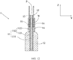
FIG. 12 is a schematic diagram of an electrode plate according to the present disclosure. -
1 electrode plate 1B negative electrode plate 11 current collector 2 case 111 insulating layer 3 top cover 112 conductive layer 4 electrode terminal 1121 main body portion 5 separator 1122 protrusion portion 6 connecting piece 12 active material layer P current guiding portion 13 conductive structure W welded zone 14 first protective layer X length direction 15 second protective layer Y thickness direction 16 third protective layer Z height direction - Referring to
FIG. 3 , a secondary battery includes an electrode assembly, a case 2, atop cover 3, an electrode terminal 4, and a connecting piece 6. - Referring to
FIG. 4 , an electrode assembly includes apositive electrode plate 1A, anegative electrode plate 1B and aseparator 5. The separator is disposed between thepositive electrode plate 1A and thenegative electrode plate 1B. Thepositive electrode plate 1A, theseparator 5 and thenegative electrode plate 1B are stacked in sequence and wound to form a jelly roll-shaped electrode assembly. - The case 2 can have a hexahedral shape or other shape. A cavity is formed inside the case 2 to accommodate the electrode assembly and electrolyte. The case 2 has an opening at an end through which the electrode assembly can be placed into the cavity of the case 2. The case 2 can be made of a conductive metal material such as aluminum or aluminum alloy, or an insulating material such as plastic.
- The
top cover 3 is provided on the case 2 and covers the opening of the case 2 to seal the electrode assembly within the case 2. The electrode terminal 4 is disposed on thetop cover 3. The electrode terminal 4 has an upper end protruding from an upper side of thetop cover 3, and a lower end passing through thetop cover 3 and extending into the case 2. The connecting piece 6 is disposed in the case 2 and is fixed to the electrode terminal 4. There are two electrode terminals 4 and two connecting piece 6. Thepositive electrode plate 1A is electrically connected to one of the two electrode terminals 4 via one of the two connecting pieces 6, and thenegative electrode plate 1B is electrically connected to the other of the two electrode terminals 4 via the other of the two connecting pieces 6. - In the secondary battery according to the present disclosure, at least one of the
positive electrode plate 1A and thenegative electrode plate 1B is an electrode plate described below. - Referring to
FIGs 5-9 , not according to the present invention, anelectrode plate 1 includes acurrent collector 11, anactive material layer 12, aconductive structure 13 and a firstprotective layer 14. Thecurrent collector 11 includes an insulatinglayer 111 and aconductive layer 112 disposed on the insulatinglayer 111. Theconductive layer 112 includes amain body portion 1121 and aprotrusion portion 1122 connected to themain body portion 1121. A surface of themain body portion 1121 facing away from the insulatinglayer 111 is covered by theactive material layer 12, and a surface of theprotrusion portion 1122 facing away from the insulatinglayer 111 is uncovered by theactive material layer 12. Theconductive structure 13 is welded to theprotrusion portion 1122 and thus a welded zone W is formed. The firstprotective layer 14 has elasticity and is disposed on a side of theprotrusion portion 1122 facing away from the insulatinglayer 111 and is located between the welded zone W and theactive material layer 12. - A portion of the insulating
layer 111 corresponding to theprotrusion portion 1122 together with theprotrusion portion 1122 forms a current guiding portion P. Referring toFIG. 5 , theelectrode plate 1 can include a plurality of current guiding portions P and a plurality ofconductive structures 13. Once theelectrode plate 1 is formed by winding, the plurality of current guiding portions P of theelectrode plate 1 is stacked, the plurality ofconductive structures 13 is opposed to each other, and each two adjacent current guiding portions P have aconductive structure 13 therebetween. Referring toFIG. 3 , the plurality ofconductive structures 13 is welded to a connecting piece 6, so that current on theconductive layers 112 on both sides of the insulatinglayer 111 converges onto an electrode terminal 4. - Since the
current collector 11 of theelectrode plate 1 is provided with the insulatinglayer 111, the thickness of theconductive layer 112 can be reduced. When a foreign matter pierces theelectrode plate 1, due to the small thickness of theconductive layer 112, burr produced at a position of theconductive layer 112 where it is pierced by the foreign matter is too small to pierce aseparator 5, thereby avoiding a short circuit and improving the safety performance. Referring toFIG. 10 , the current guiding portion P can be bent at the region between the welded zone W and theactive material layer 12, such that the space in height occupied by the current guiding portion P and theconductive structure 13 can be reduced, thereby enhancing the energy density of the secondary battery. The firstprotective layer 14 can protect theprotrusion portion 1122 from being broken when being bent, and thus guarantee the current passing performance of theprotrusion portion 1122. In the meantime, the firstprotective layer 14, due to its elasticity, can be bent together with the current guiding portion P, avoiding increasing the difficulty of bending the current guiding portion P. - After the current guiding portion P is bent, the first
protective layer 14 and theprotrusion portion 1122 disposed opposite to the firstprotective layer 14 are both bent with respect to themain body portion 1121. An end of theconductive structure 13 away from theactive material layer 12 can extend beyond an end of theprotrusion portion 1122 away from themain body portion 1121, and the exceeding portion can be bent to reduce the space occupied by theconductive structure 13 in a thickness direction Y. - The
electrode plate 1 can be formed according to following steps of: 1. applying theactive material layer 12 to a surface of theconductive layer 112 of thecurrent collector 11; 2. rolling theactive material layer 12 to compact theactive material layer 12; 3. performing cutting to get theprotrusion portion 1122 in a desired shape and the portion of insulatinglayer 111 corresponding to theprotrusion portion 1122; 4. welding theconductive structure 13 to theprotrusion portion 1122 and forming a welded zone W; and 5. applying a paste, such as an insulating glue, to the region of theprotrusion portion 1122 between the welded zone W and theactive material layer 12, thereby forming the firstprotective layer 14 having elasticity after curing of the paste. - The
conductive layer 112 fully covers each surface of the insulatinglayer 111. The insulatinglayer 111 has a thickness of 1µm to 20 µm. Theconductive layer 112 has a thickness of 0.1 µm to 10 µm. Theconductive structure 13 has a thickness of 6 µm to 15 µm. Since theconductive layer 112 is relatively thin, burr formed on theconductive layer 112 during the cutting process is too small to pierce theseparator 5 having a thickness of dozens of micrometers, thereby avoiding a short circuit and improving safety performance. - Referring to
FIG. 8 , in the thickness direction Y, a surface of the firstprotective layer 14 facing away from theprotrusion portion 1122 is lower than a surface of theactive material layer 12 facing away from themain body portion 1121, i.e., the surface of the firstprotective layer 14 facing away from theprotrusion portion 1122 is closer to the insulating layer than the surface of theactive material layer 12 facing away from themain body portion 1121, so that the firstprotective layer 14 will not result in an increase in an overall thickness of theelectrode plate 1, guaranteeing a high energy density of the secondary battery. - The first
protective layer 14 can be directly disposed on the surface of theprotrusion portion 1122 facing away from the insulatinglayer 111 to be in direct contact with theprotrusion portion 1122. Alternatively, the firstprotective layer 14 also can be disposed on a surface of a coating, which is provided on the surface of theprotrusion portion 1122 facing away from the insulatinglayer 111. - The first
protective layer 14 has a smaller modulus of elasticity than theprotrusion portion 1122. Since the firstprotective layer 14 is located outside of theprotrusion portion 1122, after the current guiding portion P is bent, an amount of deformation of the firstprotective layer 14 should be larger than an amount of deformation of theprotrusion portion 1122. If the firstprotective layer 14 has a greater modulus of elasticity than theprotrusion portion 1122, the amount of deformation of the firstprotective layer 14 will be smaller than the amount of deformation of theprotrusion portion 1122 when the current guiding portion P is bent, which may lead to a relative slide or even a detachment between the firstprotective layer 14 and the current guiding portion P. - The first
protective layer 14 is respectively connected to an end of theactive material layer 12 close to theconductive structure 13 and an end of theconductive structure 13 close to theactive material layer 12, so that the firstprotective layer 14 can be simultaneously fixed to theactive material layer 12, theconductive structure 13 and theprotrusion portion 1122. In this way, a bonding force of the firstprotective layer 14 on theelectrode plate 1 can be increased, thereby preventing the firstprotective layer 14 from peeling off together with theprotrusion portion 1122. - Referring to
FIG. 11 , theelectrode plate 1 further includes a secondprotective layer 15 disposed between the firstprotective layer 14 and theactive material layer 12, and the secondprotective layer 15 has a greater hardness than theconductive layer 112. - After the
active material layer 12 is applied to theconductive layer 112, theelectrode plate 1 should be rolled to make theactive material layer 12 thinner, so as to increase the energy density. However, during the rolling process, the roller will exert force directly on theactive material layer 12, but not on theprotrusion portion 1122 since theprotrusion portion 1122 of the conductive layer 113 is uncoated with theactive material layer 12. Since the insulating layer 111has a smaller modulus of elasticity than theconductive layer 112, an amount of deformation of the insulating layer 111is larger than an amount of deformation of theconductive layer 112 under the force of the roller, which can lead to a bulge at the interface between themain body portion 1121 and theprotrusion portion 1122. A deformation of bugle on the insulatinglayer 111 would also result in a bugle of theprotrusion portion 1122, so that theprotrusion portion 1122 is likely to be bent and crack, thereby degrading the current passing performance of theprotrusion portion 1122. By providing the secondprotective layer 15, the deformation of theprotrusion portion 1122 can be restricted, and thus theprotrusion portion 1122 can be prevented from being broken during the rolling process and the current passing performance of theelectrode plate 1 can be improved. - The second
protective layer 15 has a relative great hardness and thus is unlikely to be bent, so that the current guiding portion P should be bent in the region covered by the firstprotective layer 14. - The second
protective layer 15 is connected to theactive material layer 12, and the firstprotective layer 14 is respectively connected to an end of the secondprotective layer 15 away from theactive material layer 12 and an end of theconductive structure 13 close to theactive material layer 12. The firstprotective layer 14, the secondprotective layer 15 and theconductive structure 13 are connected as a whole, so that a bonding force of the firstprotective layer 14 and the secondprotective layer 15 on theelectrode plate 1 can be increased, thereby preventing the firstprotective layer 14 and the secondprotective layer 15 from peeling off together with theprotrusion portion 1122. In addition, the secondprotective layer 15 is connected to theactive material layer 12, so that the secondprotective layer 15 can cover the junction between themain body portion 1121 and theprotrusion portion 1122. In this way, theprotrusion portion 1122 can be protected from being broken, and the current passing performance of theelectrode plate 1 can be enhanced. - Referring to
FIG. 12 , according to the present invention, theelectrode plate 1 includes a thirdprotective layer 16 covering a surface of the welded zone W facing away from theprotrusion portion 1122. The rough surface of the welded zone W facing away from theprotrusion portion 1122 might pierce theseparator 5, causing a short circuit. The thirdprotective layer 16 separates theseparator 5 from the surface of the welded zone W, and prevents theseparator 5 from being pierced, thereby improving the safety performance. - The third
protective layer 16 is connected to the firstprotective layer 14, and is made of a material same as the firstprotective layer 14. During the forming process of theelectrode plate 1, the paste can be applied to the region of theprotrusion portion 1122 located between the welded zone W and theactive material layer 12 as well as to a surface of the welded zone W facing away from theprotrusion portion 1122, so as to form the firstprotective layer 14 and the thirdprotective layer 16 that are connected with one another after curing of the paste. - Referring to
FIG. 7 , the firstprotective layer 14 extends to edges of both sides of theprotrusion portion 1122 in a length direction X, so as to maximize a coverage area of the firstprotective layer 14 and improve the protection effect of the firstprotective layer 14. The firstprotective layer 14 has a dimension L1 in a range of 0.1mm to 4 mm along a height direction Z.
Claims (11)
- A secondary battery, comprising an electrode assembly, a case (2), a top cover (3), an electrode terminal (4), and a connecting piece (6), wherein the electrode assembly comprises an electrode plate (1) comprising:a current collector (11);an active material layer (12);a conductive structure (13);a first protective layer (14); anda third protective layer (16),wherein the current collector (11) comprises an insulating layer (111) and a conductive layer (112) disposed on the insulating layer (111), the conductive layer (112) includes a main body portion (1121) and a protrusion portion (1122) connected to the main body portion (1121), a surface of the main body portion (1121) facing away from the insulating layer (111) is covered by the active material layer (12), and a surface of the protrusion portion (1122) facing away from the insulating layer (111) is uncovered by the active material layer (12),the conductive structure (13) is welded to the protrusion portion (1122) and thus a welded zone (W) is formed,the first protective layer (14) has elasticity, and the first protective layer (14) is disposed on a side of the protrusion portion (1122) facing away from the insulating layer (111) and is located between the welded zone (W) and the active material layer (12), andthe third protective layer (16) covers a surface of the welded zone (W) facing away from the protrusion portion (1122).
- The secondary battery according to claim 1, wherein in a thickness direction (Y) of the electrode plate (1), a surface of the first protective layer (14) facing away from the protrusion portion (1122) is closer to the insulating layer (111) than a surface of the active material layer (12) facing away from the main body portion (1121).
- The secondary battery according to any one of claims 1 to 2, characterized in that the first protective layer (14) is connected to an end of the active material layer (12) close to the conductive structure (13) and an end of the conductive structure (13) close to the active material layer (12).
- The secondary battery according to any one of claims 1 to 3, characterized in that the first protective layer (14) is in contact with the protrusion portion (1122), and the first protective layer (14) has a smaller modulus of elasticity than the protrusion portion (1122).
- The secondary battery according to any one of claims 1, 2 and 4, characterized in further comprising a second protective layer (15) disposed between the first protective layer (14) and the active material layer (12), wherein the second protective layer (15) has a greater hardness than the conductive layer (112).
- The secondary battery according to claim 5, characterized in that the second protective layer (15) is connected to the active material layer (12), and the first protective layer (14) is connected to an end of the second protective layer (15) away from the active material layer (12) and an end of the conductive structure (13) close to the active material layer (12).
- The secondary battery according to any one of claims 1 to 6, characterized in that the third protective layer (16) is connected to the first protective layer (14), and is made of a material same as the first protective layer (14).
- The secondary battery according to any one of claims 1 to 7, characterized in that the first protective layer (14) extends to edges of both sides of the protrusion portion (1122) in a length direction (X) of the electrode plate (1), and the first protective layer (14) has a dimension (L1) in a range of 0.1mm to 4 mm along a height direction (Z) of the electrode plate (1).
- The secondary battery according to any one of claims 1 to 8, characterized in that a portion of the insulating layer (111) corresponding to the protrusion portion (1122) and the protrusion portion (1122) together form a current guiding portion (P),the electrode plate (1) includes a plurality of current guiding portions (P) and a plurality of conductive structures (13), the plurality of current guiding portions (P) is stacked, and every two adjacent current guiding portions (P) of the plurality of current guiding portions (P) have a conductive structure (13) of the plurality of conductive structures (13) therebetween, andthe first protective layer (14) and the protrusion portion (1122) disposed opposite to the first protective layer (14) are both bent with respect to the main body portion (1121).
- The secondary battery according to any one of claims 1 to 9, characterized in that the connecting piece (6) is disposed in the case (2) and is fixed to the electrode terminal (4), the plurality of conductive structures (13) is welded to the connecting piece (6).
- The secondary battery according to any one of claims 1 to 10, characterized in that the top cover (3) is provided on the case (2) and covers an opening of the case (2) to seal the electrode assembly within the case (2), and the electrode terminal (4) is disposed on the top cover (3).
Applications Claiming Priority (2)
| Application Number | Priority Date | Filing Date | Title |
|---|---|---|---|
| CN201821018434.4U CN208507818U (en) | 2018-06-29 | 2018-06-29 | Secondary cell and its pole piece |
| EP19154089.7A EP3588619B1 (en) | 2018-06-29 | 2019-01-29 | Secondary battery and electrode plate thereof |
Related Parent Applications (2)
| Application Number | Title | Priority Date | Filing Date |
|---|---|---|---|
| EP19154089.7A Division EP3588619B1 (en) | 2018-06-29 | 2019-01-29 | Secondary battery and electrode plate thereof |
| EP19154089.7A Division-Into EP3588619B1 (en) | 2018-06-29 | 2019-01-29 | Secondary battery and electrode plate thereof |
Publications (2)
| Publication Number | Publication Date |
|---|---|
| EP3832790A1 EP3832790A1 (en) | 2021-06-09 |
| EP3832790B1 true EP3832790B1 (en) | 2022-03-30 |
Family
ID=65243345
Family Applications (2)
| Application Number | Title | Priority Date | Filing Date |
|---|---|---|---|
| EP19154089.7A Active EP3588619B1 (en) | 2018-06-29 | 2019-01-29 | Secondary battery and electrode plate thereof |
| EP20217502.2A Active EP3832790B1 (en) | 2018-06-29 | 2019-01-29 | Secondary battery and electrode plate thereof |
Family Applications Before (1)
| Application Number | Title | Priority Date | Filing Date |
|---|---|---|---|
| EP19154089.7A Active EP3588619B1 (en) | 2018-06-29 | 2019-01-29 | Secondary battery and electrode plate thereof |
Country Status (4)
| Country | Link |
|---|---|
| US (2) | US11239468B2 (en) |
| EP (2) | EP3588619B1 (en) |
| CN (1) | CN208507818U (en) |
| PL (1) | PL3588619T3 (en) |
Families Citing this family (35)
| Publication number | Priority date | Publication date | Assignee | Title |
|---|---|---|---|---|
| CN209183628U (en) | 2018-10-11 | 2019-07-30 | 宁德时代新能源科技股份有限公司 | Secondary battery and its pole piece |
| CN110660957B (en) | 2018-12-29 | 2020-12-04 | 宁德时代新能源科技股份有限公司 | An electrode pole piece and electrochemical device |
| CN110661002B (en) | 2018-12-29 | 2021-06-29 | 宁德时代新能源科技股份有限公司 | Electrode plate and electrochemical device |
| CN110676460B (en) | 2018-12-29 | 2022-01-18 | 宁德时代新能源科技股份有限公司 | Electrode plate and electrochemical device |
| CN110660963B (en) | 2018-12-29 | 2021-04-27 | 宁德时代新能源科技股份有限公司 | An electrode pole piece and electrochemical device |
| CN110943200B (en) | 2019-04-15 | 2021-03-09 | 宁德时代新能源科技股份有限公司 | An electrode pole piece and electrochemical device |
| CN110943201B (en) | 2019-04-15 | 2021-02-26 | 宁德时代新能源科技股份有限公司 | A positive electrode plate and electrochemical device |
| CN110943222B (en) | 2019-04-15 | 2021-01-12 | 宁德时代新能源科技股份有限公司 | Electrode plate and electrochemical device |
| CN111952655B (en) | 2019-05-17 | 2024-01-26 | 宁德时代新能源科技股份有限公司 | Secondary battery |
| CN111180666B (en) * | 2019-06-28 | 2021-12-24 | 宁德时代新能源科技股份有限公司 | Electrode plate and electrochemical device |
| CN111180665A (en) * | 2019-06-28 | 2020-05-19 | 宁德时代新能源科技股份有限公司 | An electrode pole piece and electrochemical device |
| CN111326699B (en) * | 2019-08-14 | 2021-11-09 | 宁德时代新能源科技股份有限公司 | Secondary battery |
| CN210136972U (en) * | 2019-08-27 | 2020-03-10 | 宁德时代新能源科技股份有限公司 | Secondary battery |
| CN112448043A (en) * | 2019-08-30 | 2021-03-05 | 中科邦汇新材料科技(东莞)有限公司 | Novel lithium battery cathode and anode sheet insulating glue process |
| KR102424631B1 (en) * | 2019-12-24 | 2022-07-25 | 주식회사 유앤에스에너지 | Current collector for positive electrodes |
| CN111509180B (en) * | 2020-03-26 | 2022-04-12 | 合肥国轩高科动力能源有限公司 | Lithium battery cell with conductive tabs |
| JP7678526B2 (en) | 2020-03-31 | 2025-05-16 | パナソニックIpマネジメント株式会社 | Sealing body and battery |
| KR102852580B1 (en) * | 2020-04-16 | 2025-08-28 | 주식회사 엘지에너지솔루션 | Secondary battery electrode |
| CN213340434U (en) * | 2020-09-22 | 2021-06-01 | 宁德时代新能源科技股份有限公司 | Electrode assembly, battery cell, battery, and power consumption device |
| KR102751794B1 (en) * | 2020-10-20 | 2025-01-07 | 컨템포러리 엠퍼렉스 테크놀로지 (홍콩) 리미티드 | Electrode assembly, battery cell, battery, power consumption device, manufacturing method and equipment |
| CN112290030A (en) * | 2020-11-09 | 2021-01-29 | 武汉逸飞激光股份有限公司 | Electrode plate and energy storage device |
| CN114583178A (en) * | 2020-11-30 | 2022-06-03 | 比亚迪股份有限公司 | A battery current collector and lithium ion battery |
| CN214043710U (en) * | 2020-12-28 | 2021-08-24 | 珠海冠宇电池股份有限公司 | Positive plate and lithium ion battery |
| WO2022246629A1 (en) * | 2021-05-25 | 2022-12-01 | 宁德新能源科技有限公司 | Battery and electronic device |
| CN113644277B (en) * | 2021-08-09 | 2022-10-14 | 宁德新能源科技有限公司 | Electrochemical device and electricity utilization device |
| CN115863536B (en) * | 2021-09-27 | 2025-04-15 | 宁德时代新能源科技股份有限公司 | Electrode assembly, manufacturing method and system, battery cell, battery and electrical device |
| CN114373886A (en) * | 2021-12-31 | 2022-04-19 | 东莞新能源科技有限公司 | Battery and electronic equipment |
| JP7727000B2 (en) * | 2022-02-23 | 2025-08-20 | 香港時代新能源科技有限公司 | Electrode plate, electrode assembly and secondary battery |
| WO2023216076A1 (en) * | 2022-05-09 | 2023-11-16 | 宁德时代新能源科技股份有限公司 | Pole piece, battery cell, battery and electrical apparatus |
| JP2025531522A (en) * | 2022-09-29 | 2025-09-19 | 寧徳新能源科技有限公司 | Electrochemical equipment and power consumers |
| CN116802920A (en) * | 2022-09-29 | 2023-09-22 | 宁德新能源科技有限公司 | Electrochemical devices and electrical equipment |
| WO2024065364A1 (en) * | 2022-09-29 | 2024-04-04 | 宁德新能源科技有限公司 | Electrochemical apparatus and electrical device |
| WO2024148486A1 (en) * | 2023-01-09 | 2024-07-18 | 宁德时代新能源科技股份有限公司 | Electrode sheet, electrode assembly, battery cell, battery, and electrical device |
| WO2025069746A1 (en) * | 2023-09-29 | 2025-04-03 | パナソニックIpマネジメント株式会社 | Secondary battery |
| CN117239058B (en) * | 2023-11-13 | 2024-03-01 | 珠海冠宇电池股份有限公司 | Pole piece, battery cell and battery |
Family Cites Families (5)
| Publication number | Priority date | Publication date | Assignee | Title |
|---|---|---|---|---|
| JP4780598B2 (en) * | 2004-09-29 | 2011-09-28 | 日立マクセルエナジー株式会社 | Sealed prismatic battery |
| JP5260838B2 (en) * | 2005-08-30 | 2013-08-14 | 三洋電機株式会社 | Non-aqueous secondary battery |
| US8734986B2 (en) * | 2007-07-11 | 2014-05-27 | Nissan Motor Co., Ltd. | Laminate type battery |
| KR101315672B1 (en) * | 2012-07-06 | 2013-10-08 | (주)오렌지파워 | Electrode assembly, battery having the same and method of fabricating battery |
| JP6735445B2 (en) * | 2014-06-26 | 2020-08-05 | パナソニックIpマネジメント株式会社 | Wound battery |
-
2018
- 2018-06-29 CN CN201821018434.4U patent/CN208507818U/en active Active
-
2019
- 2019-01-29 PL PL19154089T patent/PL3588619T3/en unknown
- 2019-01-29 EP EP19154089.7A patent/EP3588619B1/en active Active
- 2019-01-29 EP EP20217502.2A patent/EP3832790B1/en active Active
- 2019-04-04 US US16/375,531 patent/US11239468B2/en active Active
-
2021
- 2021-12-07 US US17/543,954 patent/US11631862B2/en active Active
Also Published As
| Publication number | Publication date |
|---|---|
| US11239468B2 (en) | 2022-02-01 |
| PL3588619T3 (en) | 2021-08-30 |
| US20220093934A1 (en) | 2022-03-24 |
| US11631862B2 (en) | 2023-04-18 |
| EP3588619A1 (en) | 2020-01-01 |
| EP3588619B1 (en) | 2021-03-03 |
| US20200006776A1 (en) | 2020-01-02 |
| EP3832790A1 (en) | 2021-06-09 |
| CN208507818U (en) | 2019-02-15 |
Similar Documents
| Publication | Publication Date | Title |
|---|---|---|
| EP3832790B1 (en) | Secondary battery and electrode plate thereof | |
| EP3588620B1 (en) | Secondary battery and electrode plate thereof | |
| US20240088396A1 (en) | Secondary battery and electrode plate | |
| EP3852165B1 (en) | Secondary battery and manufacturing method for secondary battery | |
| EP3637504B1 (en) | Secondary battery and electrode plate thereof | |
| US11196131B2 (en) | Secondary battery | |
| EP3940855A1 (en) | Electrode assembly and battery | |
| EP2136424A1 (en) | Tab for a Lithium Secondary Battery | |
| EP3703160B1 (en) | Secondary battery | |
| US20180108879A1 (en) | Battery structure | |
| US11145868B2 (en) | Electrode piece, cell and energy storage device | |
| US20200091485A1 (en) | Secondary battery | |
| EP3309857A1 (en) | Battery structure | |
| JP2013073872A (en) | Laminated battery | |
| KR102927442B1 (en) | Secondary battery | |
| KR100635716B1 (en) | Secondary battery |
Legal Events
| Date | Code | Title | Description |
|---|---|---|---|
| PUAI | Public reference made under article 153(3) epc to a published international application that has entered the european phase |
Free format text: ORIGINAL CODE: 0009012 |
|
| STAA | Information on the status of an ep patent application or granted ep patent |
Free format text: STATUS: THE APPLICATION HAS BEEN PUBLISHED |
|
| AC | Divisional application: reference to earlier application |
Ref document number: 3588619 Country of ref document: EP Kind code of ref document: P |
|
| AK | Designated contracting states |
Kind code of ref document: A1 Designated state(s): AL AT BE BG CH CY CZ DE DK EE ES FI FR GB GR HR HU IE IS IT LI LT LU LV MC MK MT NL NO PL PT RO RS SE SI SK SM TR |
|
| STAA | Information on the status of an ep patent application or granted ep patent |
Free format text: STATUS: REQUEST FOR EXAMINATION WAS MADE |
|
| 17P | Request for examination filed |
Effective date: 20210910 |
|
| RBV | Designated contracting states (corrected) |
Designated state(s): AL AT BE BG CH CY CZ DE DK EE ES FI FR GB GR HR HU IE IS IT LI LT LU LV MC MK MT NL NO PL PT RO RS SE SI SK SM TR |
|
| REG | Reference to a national code |
Ref country code: DE Ref legal event code: R079 Ref document number: 602019013224 Country of ref document: DE Free format text: PREVIOUS MAIN CLASS: H01M0050531000 Ipc: H01M0050536000 |
|
| STAA | Information on the status of an ep patent application or granted ep patent |
Free format text: STATUS: EXAMINATION IS IN PROGRESS |
|
| RIC1 | Information provided on ipc code assigned before grant |
Ipc: H01M 50/531 20210101ALI20211022BHEP Ipc: H01M 4/66 20060101ALI20211022BHEP Ipc: H01M 10/04 20060101ALI20211022BHEP Ipc: H01M 50/536 20210101AFI20211022BHEP |
|
| GRAP | Despatch of communication of intention to grant a patent |
Free format text: ORIGINAL CODE: EPIDOSNIGR1 |
|
| STAA | Information on the status of an ep patent application or granted ep patent |
Free format text: STATUS: GRANT OF PATENT IS INTENDED |
|
| 17Q | First examination report despatched |
Effective date: 20211112 |
|
| INTG | Intention to grant announced |
Effective date: 20211206 |
|
| GRAS | Grant fee paid |
Free format text: ORIGINAL CODE: EPIDOSNIGR3 |
|
| GRAA | (expected) grant |
Free format text: ORIGINAL CODE: 0009210 |
|
| STAA | Information on the status of an ep patent application or granted ep patent |
Free format text: STATUS: THE PATENT HAS BEEN GRANTED |
|
| AC | Divisional application: reference to earlier application |
Ref document number: 3588619 Country of ref document: EP Kind code of ref document: P |
|
| AK | Designated contracting states |
Kind code of ref document: B1 Designated state(s): AL AT BE BG CH CY CZ DE DK EE ES FI FR GB GR HR HU IE IS IT LI LT LU LV MC MK MT NL NO PL PT RO RS SE SI SK SM TR |
|
| REG | Reference to a national code |
Ref country code: GB Ref legal event code: FG4D |
|
| REG | Reference to a national code |
Ref country code: CH Ref legal event code: EP |
|
| REG | Reference to a national code |
Ref country code: DE Ref legal event code: R096 Ref document number: 602019013224 Country of ref document: DE |
|
| REG | Reference to a national code |
Ref country code: AT Ref legal event code: REF Ref document number: 1480040 Country of ref document: AT Kind code of ref document: T Effective date: 20220415 |
|
| REG | Reference to a national code |
Ref country code: SE Ref legal event code: TRGR |
|
| REG | Reference to a national code |
Ref country code: IE Ref legal event code: FG4D |
|
| REG | Reference to a national code |
Ref country code: NL Ref legal event code: FP |
|
| REG | Reference to a national code |
Ref country code: LT Ref legal event code: MG9D |
|
| PG25 | Lapsed in a contracting state [announced via postgrant information from national office to epo] |
Ref country code: RS Free format text: LAPSE BECAUSE OF FAILURE TO SUBMIT A TRANSLATION OF THE DESCRIPTION OR TO PAY THE FEE WITHIN THE PRESCRIBED TIME-LIMIT Effective date: 20220330 Ref country code: NO Free format text: LAPSE BECAUSE OF FAILURE TO SUBMIT A TRANSLATION OF THE DESCRIPTION OR TO PAY THE FEE WITHIN THE PRESCRIBED TIME-LIMIT Effective date: 20220630 Ref country code: LT Free format text: LAPSE BECAUSE OF FAILURE TO SUBMIT A TRANSLATION OF THE DESCRIPTION OR TO PAY THE FEE WITHIN THE PRESCRIBED TIME-LIMIT Effective date: 20220330 Ref country code: HR Free format text: LAPSE BECAUSE OF FAILURE TO SUBMIT A TRANSLATION OF THE DESCRIPTION OR TO PAY THE FEE WITHIN THE PRESCRIBED TIME-LIMIT Effective date: 20220330 Ref country code: BG Free format text: LAPSE BECAUSE OF FAILURE TO SUBMIT A TRANSLATION OF THE DESCRIPTION OR TO PAY THE FEE WITHIN THE PRESCRIBED TIME-LIMIT Effective date: 20220630 |
|
| REG | Reference to a national code |
Ref country code: AT Ref legal event code: MK05 Ref document number: 1480040 Country of ref document: AT Kind code of ref document: T Effective date: 20220330 |
|
| PG25 | Lapsed in a contracting state [announced via postgrant information from national office to epo] |
Ref country code: LV Free format text: LAPSE BECAUSE OF FAILURE TO SUBMIT A TRANSLATION OF THE DESCRIPTION OR TO PAY THE FEE WITHIN THE PRESCRIBED TIME-LIMIT Effective date: 20220330 Ref country code: GR Free format text: LAPSE BECAUSE OF FAILURE TO SUBMIT A TRANSLATION OF THE DESCRIPTION OR TO PAY THE FEE WITHIN THE PRESCRIBED TIME-LIMIT Effective date: 20220701 Ref country code: FI Free format text: LAPSE BECAUSE OF FAILURE TO SUBMIT A TRANSLATION OF THE DESCRIPTION OR TO PAY THE FEE WITHIN THE PRESCRIBED TIME-LIMIT Effective date: 20220330 |
|
| PG25 | Lapsed in a contracting state [announced via postgrant information from national office to epo] |
Ref country code: SM Free format text: LAPSE BECAUSE OF FAILURE TO SUBMIT A TRANSLATION OF THE DESCRIPTION OR TO PAY THE FEE WITHIN THE PRESCRIBED TIME-LIMIT Effective date: 20220330 Ref country code: SK Free format text: LAPSE BECAUSE OF FAILURE TO SUBMIT A TRANSLATION OF THE DESCRIPTION OR TO PAY THE FEE WITHIN THE PRESCRIBED TIME-LIMIT Effective date: 20220330 Ref country code: RO Free format text: LAPSE BECAUSE OF FAILURE TO SUBMIT A TRANSLATION OF THE DESCRIPTION OR TO PAY THE FEE WITHIN THE PRESCRIBED TIME-LIMIT Effective date: 20220330 Ref country code: PT Free format text: LAPSE BECAUSE OF FAILURE TO SUBMIT A TRANSLATION OF THE DESCRIPTION OR TO PAY THE FEE WITHIN THE PRESCRIBED TIME-LIMIT Effective date: 20220801 Ref country code: ES Free format text: LAPSE BECAUSE OF FAILURE TO SUBMIT A TRANSLATION OF THE DESCRIPTION OR TO PAY THE FEE WITHIN THE PRESCRIBED TIME-LIMIT Effective date: 20220330 Ref country code: EE Free format text: LAPSE BECAUSE OF FAILURE TO SUBMIT A TRANSLATION OF THE DESCRIPTION OR TO PAY THE FEE WITHIN THE PRESCRIBED TIME-LIMIT Effective date: 20220330 Ref country code: AT Free format text: LAPSE BECAUSE OF FAILURE TO SUBMIT A TRANSLATION OF THE DESCRIPTION OR TO PAY THE FEE WITHIN THE PRESCRIBED TIME-LIMIT Effective date: 20220330 |
|
| PG25 | Lapsed in a contracting state [announced via postgrant information from national office to epo] |
Ref country code: PL Free format text: LAPSE BECAUSE OF FAILURE TO SUBMIT A TRANSLATION OF THE DESCRIPTION OR TO PAY THE FEE WITHIN THE PRESCRIBED TIME-LIMIT Effective date: 20220330 Ref country code: IS Free format text: LAPSE BECAUSE OF FAILURE TO SUBMIT A TRANSLATION OF THE DESCRIPTION OR TO PAY THE FEE WITHIN THE PRESCRIBED TIME-LIMIT Effective date: 20220730 Ref country code: AL Free format text: LAPSE BECAUSE OF FAILURE TO SUBMIT A TRANSLATION OF THE DESCRIPTION OR TO PAY THE FEE WITHIN THE PRESCRIBED TIME-LIMIT Effective date: 20220330 |
|
| REG | Reference to a national code |
Ref country code: DE Ref legal event code: R097 Ref document number: 602019013224 Country of ref document: DE |
|
| PG25 | Lapsed in a contracting state [announced via postgrant information from national office to epo] |
Ref country code: DK Free format text: LAPSE BECAUSE OF FAILURE TO SUBMIT A TRANSLATION OF THE DESCRIPTION OR TO PAY THE FEE WITHIN THE PRESCRIBED TIME-LIMIT Effective date: 20220330 |
|
| PLBE | No opposition filed within time limit |
Free format text: ORIGINAL CODE: 0009261 |
|
| STAA | Information on the status of an ep patent application or granted ep patent |
Free format text: STATUS: NO OPPOSITION FILED WITHIN TIME LIMIT |
|
| 26N | No opposition filed |
Effective date: 20230103 |
|
| PG25 | Lapsed in a contracting state [announced via postgrant information from national office to epo] |
Ref country code: SI Free format text: LAPSE BECAUSE OF FAILURE TO SUBMIT A TRANSLATION OF THE DESCRIPTION OR TO PAY THE FEE WITHIN THE PRESCRIBED TIME-LIMIT Effective date: 20220330 |
|
| P01 | Opt-out of the competence of the unified patent court (upc) registered |
Effective date: 20230516 |
|
| REG | Reference to a national code |
Ref country code: CH Ref legal event code: PL |
|
| PG25 | Lapsed in a contracting state [announced via postgrant information from national office to epo] |
Ref country code: LU Free format text: LAPSE BECAUSE OF NON-PAYMENT OF DUE FEES Effective date: 20230129 |
|
| REG | Reference to a national code |
Ref country code: BE Ref legal event code: MM Effective date: 20230131 |
|
| PG25 | Lapsed in a contracting state [announced via postgrant information from national office to epo] |
Ref country code: LI Free format text: LAPSE BECAUSE OF NON-PAYMENT OF DUE FEES Effective date: 20230131 Ref country code: CH Free format text: LAPSE BECAUSE OF NON-PAYMENT OF DUE FEES Effective date: 20230131 |
|
| PG25 | Lapsed in a contracting state [announced via postgrant information from national office to epo] |
Ref country code: BE Free format text: LAPSE BECAUSE OF NON-PAYMENT OF DUE FEES Effective date: 20230131 |
|
| PG25 | Lapsed in a contracting state [announced via postgrant information from national office to epo] |
Ref country code: IE Free format text: LAPSE BECAUSE OF NON-PAYMENT OF DUE FEES Effective date: 20230129 |
|
| PG25 | Lapsed in a contracting state [announced via postgrant information from national office to epo] |
Ref country code: MC Free format text: LAPSE BECAUSE OF FAILURE TO SUBMIT A TRANSLATION OF THE DESCRIPTION OR TO PAY THE FEE WITHIN THE PRESCRIBED TIME-LIMIT Effective date: 20220330 |
|
| PG25 | Lapsed in a contracting state [announced via postgrant information from national office to epo] |
Ref country code: MC Free format text: LAPSE BECAUSE OF FAILURE TO SUBMIT A TRANSLATION OF THE DESCRIPTION OR TO PAY THE FEE WITHIN THE PRESCRIBED TIME-LIMIT Effective date: 20220330 |
|
| REG | Reference to a national code |
Ref country code: DE Ref legal event code: R081 Ref document number: 602019013224 Country of ref document: DE Owner name: CONTEMPORARY AMPEREX TECHNOLOGY (HONG KONG) LI, HK Free format text: FORMER OWNER: CONTEMPORARY AMPEREX TECHNOLOGY CO., LIMITED, NINGDE CITY, FUJIAN, CN |
|
| REG | Reference to a national code |
Ref country code: NL Ref legal event code: PD Owner name: CONTEMPORARY AMPEREX TECHNOLOGY (HONG KONG) LIMITED; CN Free format text: DETAILS ASSIGNMENT: CHANGE OF OWNER(S), ASSIGNMENT; FORMER OWNER NAME: CONTEMPORARY AMPEREX TECHNOLOGY CO., LIMITED Effective date: 20240819 |
|
| REG | Reference to a national code |
Ref country code: GB Ref legal event code: 732E Free format text: REGISTERED BETWEEN 20240829 AND 20240904 |
|
| PG25 | Lapsed in a contracting state [announced via postgrant information from national office to epo] |
Ref country code: CY Free format text: LAPSE BECAUSE OF FAILURE TO SUBMIT A TRANSLATION OF THE DESCRIPTION OR TO PAY THE FEE WITHIN THE PRESCRIBED TIME-LIMIT; INVALID AB INITIO Effective date: 20190129 |
|
| PG25 | Lapsed in a contracting state [announced via postgrant information from national office to epo] |
Ref country code: HU Free format text: LAPSE BECAUSE OF FAILURE TO SUBMIT A TRANSLATION OF THE DESCRIPTION OR TO PAY THE FEE WITHIN THE PRESCRIBED TIME-LIMIT; INVALID AB INITIO Effective date: 20190129 |
|
| PG25 | Lapsed in a contracting state [announced via postgrant information from national office to epo] |
Ref country code: TR Free format text: LAPSE BECAUSE OF FAILURE TO SUBMIT A TRANSLATION OF THE DESCRIPTION OR TO PAY THE FEE WITHIN THE PRESCRIBED TIME-LIMIT Effective date: 20220330 |
|
| PGFP | Annual fee paid to national office [announced via postgrant information from national office to epo] |
Ref country code: GB Payment date: 20251211 Year of fee payment: 8 |
|
| PGFP | Annual fee paid to national office [announced via postgrant information from national office to epo] |
Ref country code: NL Payment date: 20251215 Year of fee payment: 8 Ref country code: FR Payment date: 20251128 Year of fee payment: 8 |
|
| PGFP | Annual fee paid to national office [announced via postgrant information from national office to epo] |
Ref country code: SE Payment date: 20251210 Year of fee payment: 8 |
|
| PGFP | Annual fee paid to national office [announced via postgrant information from national office to epo] |
Ref country code: DE Payment date: 20251203 Year of fee payment: 8 |
|
| PGFP | Annual fee paid to national office [announced via postgrant information from national office to epo] |
Ref country code: IT Payment date: 20251219 Year of fee payment: 8 |
|
| PGFP | Annual fee paid to national office [announced via postgrant information from national office to epo] |
Ref country code: CZ Payment date: 20260119 Year of fee payment: 8 |