EP3832750B1 - Power supply device and vehicle equipped with same - Google Patents
Power supply device and vehicle equipped with same Download PDFInfo
- Publication number
- EP3832750B1 EP3832750B1 EP19843346.8A EP19843346A EP3832750B1 EP 3832750 B1 EP3832750 B1 EP 3832750B1 EP 19843346 A EP19843346 A EP 19843346A EP 3832750 B1 EP3832750 B1 EP 3832750B1
- Authority
- EP
- European Patent Office
- Prior art keywords
- power supply
- supply device
- plate
- secondary battery
- hole
- Prior art date
- Legal status (The legal status is an assumption and is not a legal conclusion. Google has not performed a legal analysis and makes no representation as to the accuracy of the status listed.)
- Active
Links
Images


Classifications
-
- H—ELECTRICITY
- H01—ELECTRIC ELEMENTS
- H01M—PROCESSES OR MEANS, e.g. BATTERIES, FOR THE DIRECT CONVERSION OF CHEMICAL ENERGY INTO ELECTRICAL ENERGY
- H01M50/00—Constructional details or processes of manufacture of the non-active parts of electrochemical cells other than fuel cells, e.g. hybrid cells
- H01M50/20—Mountings; Secondary casings or frames; Racks, modules or packs; Suspension devices; Shock absorbers; Transport or carrying devices; Holders
- H01M50/204—Racks, modules or packs for multiple batteries or multiple cells
- H01M50/207—Racks, modules or packs for multiple batteries or multiple cells characterised by their shape
- H01M50/209—Racks, modules or packs for multiple batteries or multiple cells characterised by their shape adapted for prismatic or rectangular cells
-
- B—PERFORMING OPERATIONS; TRANSPORTING
- B60—VEHICLES IN GENERAL
- B60K—ARRANGEMENT OR MOUNTING OF PROPULSION UNITS OR OF TRANSMISSIONS IN VEHICLES; ARRANGEMENT OR MOUNTING OF PLURAL DIVERSE PRIME-MOVERS IN VEHICLES; AUXILIARY DRIVES FOR VEHICLES; INSTRUMENTATION OR DASHBOARDS FOR VEHICLES; ARRANGEMENTS IN CONNECTION WITH COOLING, AIR INTAKE, GAS EXHAUST OR FUEL SUPPLY OF PROPULSION UNITS IN VEHICLES
- B60K1/00—Arrangement or mounting of electrical propulsion units
- B60K1/04—Arrangement or mounting of electrical propulsion units of the electric storage means for propulsion
-
- H—ELECTRICITY
- H01—ELECTRIC ELEMENTS
- H01M—PROCESSES OR MEANS, e.g. BATTERIES, FOR THE DIRECT CONVERSION OF CHEMICAL ENERGY INTO ELECTRICAL ENERGY
- H01M10/00—Secondary cells; Manufacture thereof
- H01M10/04—Construction or manufacture in general
- H01M10/0481—Compression means other than compression means for stacks of electrodes and separators
-
- H—ELECTRICITY
- H01—ELECTRIC ELEMENTS
- H01M—PROCESSES OR MEANS, e.g. BATTERIES, FOR THE DIRECT CONVERSION OF CHEMICAL ENERGY INTO ELECTRICAL ENERGY
- H01M50/00—Constructional details or processes of manufacture of the non-active parts of electrochemical cells other than fuel cells, e.g. hybrid cells
- H01M50/20—Mountings; Secondary casings or frames; Racks, modules or packs; Suspension devices; Shock absorbers; Transport or carrying devices; Holders
- H01M50/249—Mountings; Secondary casings or frames; Racks, modules or packs; Suspension devices; Shock absorbers; Transport or carrying devices; Holders specially adapted for aircraft or vehicles, e.g. cars or trains
-
- H—ELECTRICITY
- H01—ELECTRIC ELEMENTS
- H01M—PROCESSES OR MEANS, e.g. BATTERIES, FOR THE DIRECT CONVERSION OF CHEMICAL ENERGY INTO ELECTRICAL ENERGY
- H01M50/00—Constructional details or processes of manufacture of the non-active parts of electrochemical cells other than fuel cells, e.g. hybrid cells
- H01M50/20—Mountings; Secondary casings or frames; Racks, modules or packs; Suspension devices; Shock absorbers; Transport or carrying devices; Holders
- H01M50/262—Mountings; Secondary casings or frames; Racks, modules or packs; Suspension devices; Shock absorbers; Transport or carrying devices; Holders with fastening means, e.g. locks
- H01M50/264—Mountings; Secondary casings or frames; Racks, modules or packs; Suspension devices; Shock absorbers; Transport or carrying devices; Holders with fastening means, e.g. locks for cells or batteries, e.g. straps, tie rods or peripheral frames
-
- H—ELECTRICITY
- H01—ELECTRIC ELEMENTS
- H01M—PROCESSES OR MEANS, e.g. BATTERIES, FOR THE DIRECT CONVERSION OF CHEMICAL ENERGY INTO ELECTRICAL ENERGY
- H01M50/00—Constructional details or processes of manufacture of the non-active parts of electrochemical cells other than fuel cells, e.g. hybrid cells
- H01M50/20—Mountings; Secondary casings or frames; Racks, modules or packs; Suspension devices; Shock absorbers; Transport or carrying devices; Holders
- H01M50/289—Mountings; Secondary casings or frames; Racks, modules or packs; Suspension devices; Shock absorbers; Transport or carrying devices; Holders characterised by spacing elements or positioning means within frames, racks or packs
-
- H—ELECTRICITY
- H01—ELECTRIC ELEMENTS
- H01M—PROCESSES OR MEANS, e.g. BATTERIES, FOR THE DIRECT CONVERSION OF CHEMICAL ENERGY INTO ELECTRICAL ENERGY
- H01M2220/00—Batteries for particular applications
- H01M2220/20—Batteries in motive systems, e.g. vehicle, ship, plane
-
- Y—GENERAL TAGGING OF NEW TECHNOLOGICAL DEVELOPMENTS; GENERAL TAGGING OF CROSS-SECTIONAL TECHNOLOGIES SPANNING OVER SEVERAL SECTIONS OF THE IPC; TECHNICAL SUBJECTS COVERED BY FORMER USPC CROSS-REFERENCE ART COLLECTIONS [XRACs] AND DIGESTS
- Y02—TECHNOLOGIES OR APPLICATIONS FOR MITIGATION OR ADAPTATION AGAINST CLIMATE CHANGE
- Y02E—REDUCTION OF GREENHOUSE GAS [GHG] EMISSIONS, RELATED TO ENERGY GENERATION, TRANSMISSION OR DISTRIBUTION
- Y02E60/00—Enabling technologies; Technologies with a potential or indirect contribution to GHG emissions mitigation
- Y02E60/10—Energy storage using batteries
Definitions
- the present invention relates to a power supply device and a vehicle equipped with the power supply device.
- the power supply device is used as a power supply device for driving a vehicle, a power supply device for storing electricity, and the like.
- a plurality of rechargeable secondary battery cells are stacked.
- power supply device 900 has end plates 920 on both end faces of a battery stack obtained by stacking secondary battery cells 901 having square package cans. End plates 920 are fastened to each other with metal bind bars 930.
- the package can of a secondary battery cell expands and contracts when charging and discharging are repeated.
- the capacity of each secondary battery cell is increasing.
- the amount of expansion tends to increase.
- a strong load is applied to a battery stack in which a large number of such secondary battery cells are stacked and fastened.
- screws fixing the bind bars are broken.
- PTL 2 discloses a a battery pack comprising a plurality of stacked rectangular cells, a pair of end plates attached to the end faces of the cell stack, and two pairs of bind bars disposed on opposite sides of the stack, extending along the stacking direction and fastening said end plates together.
- the bind bars have a strip shape portion and two bend parts comprising each a slit, a coupling hole, which are coupled to an engagement protrusion (and to protruding parts of a positioning mechanism of the end plates.
- a power supply device includes a plurality of secondary battery cells each having a flat rectangular parallelepiped shape, a pair of end plates covering both end faces of a battery stack in which the plurality of secondary battery cells stacked, and a plurality of fastening members for fastening the end plates to each other.
- Each of the plurality of fastening members comprises a metal plate without bent edges having a plate shape extending along the stacking direction of the plurality of secondary battery cells and is disposed on a corresponding one of opposite surfaces of the battery stack. Through holes are formed in both ends of each plate shape.
- Each of the pair of end plates comprises a plate portion having a recess that receives pipe portions inserted into the through holes of a pair of fastening members disposed on opposite surfaces of the battery stack among the plurality of fastening members, wherein the pipe portion (21) has a pipe hole (22) in each of both end edges of the pipe portion (21).
- the pipe portions receive a stress over wide areas to avoid the concentration of the stress and disperse the stress, thereby improving durability and holding the fastening force of the battery stack stably for a long period of time.
- a metal is used for each bind bar provided for the power supply device exemplified in PTL 1 so as to be able to withstand a relatively strong load.
- a metal differs in strength depending on how it receives a load, such as bending strength and tensile strength.
- a typical metal used as a material for each bind bar has excellent tensile strength and is characterized in that the deformation of the bind bar can be suppressed.
- a load in the shearing direction is applied to a screw fixing each bind bar, and the screw may break.
- the amount of expansion has been increasing with the improvement of the performance of a secondary battery cell.
- the pipe portion has pipe holes in both end edges of the pipe portion.
- the power supply device further has press-fit pins press fitted into the through holes and the pipe holes.
- the press-fit pin has a flange having a larger diameter than the through hole.
- the outer shape of the pipe portion may be cylindrical, and the recess may be formed in a curved shape according to the side surface of the pipe portion.
- Battery stack 10 may have an insulating spacer interposed between the secondary battery cells stacked adjacent to each other.
- the insulating spacer is made of an insulating material such as a resin and is formed in a thin plate shape or a sheet shape.
- the insulating spacer has a plate shape having a size almost equal to the facing surface of the secondary battery cell.
- the insulating spacers can be stacked between the secondary battery cells adjacent to each other to insulate the adjacent secondary battery cells from each other.
- Both ends of fastening member 30 are fixed to end plates 20 disposed on both end faces of battery stack 10.
- End plate 20 is fixed by a plurality of fastening members 30, and battery stack 10 is fastened in the stacking direction.
- Fastening members 30 are metal plates each having a predetermined width and a predetermined thickness along the upper surface of battery stack 10, and are disposed so as to face the upper and lower surfaces of battery stack 10.
- a metal plate such as an iron plate, preferably a steel plate, can be used for fastening member 30.
- Fastening member 30 made of a metal plate is bent by press molding or the like to form a predetermined shape.
- each fastening member 30 plate-shaped without any bent portion prevents the stress from concentrating on a specific portion of fastening member 30, such as a bent portion.
- making pipe portion 21 of end plate 20 fixed to fastening member 30 also receive the stress can prevent the occurrence of the shear stress and stably maintain the fastening force of battery stack 10 for a long period of time.
- Fastening members 30 are disposed on opposite surfaces of battery stack 10. In the example illustrated in FIGS. 1 to 4 , fastening members 30 are disposed on the upper and lower surfaces of battery stack 10. In this case, as illustrated in FIG. 1 and the like, fastening member 30 is displaced from the position of electrode terminal 2 of each secondary battery cell 1 so as to expose electrode terminal 2. Further, in this configuration, by disposing fastening member 30 on the surface of sealing plate 1b of secondary battery cell 1, fastening member 30 can press the upper surface of sealing plate 1b.
- pipe portion 21 is designed to have a length substantially equal to or slightly larger than the height of plate portion 23. Accordingly, pipe hole 22 in the end face of pipe portion 21 can be fixed to fastening member 30 so as to coincide with or slightly protrude from the upper end of plate portion 23. If the through hole of the each fastening member is made larger than the outer shape of the pipe portion, the pipe portion can be easily inserted through the through hole. However, from the viewpoint of strength, the outer shape of the pipe portion is preferably nearly equal to the size of the through hole of the fastening member.
- Pipe portion 21 preferably has a columnar outer shape. Further, recess 26 of plate portion 23 is formed in a curved shape in accordance with the columnar side surface of pipe portion 21. Forming concave portion 26 into a curved portion will enhance the effect of relaxing the stress concentration by receiving the stress applied to fastening member 30 through the curved surfaces of pipe portion 21 and plate portion 23. On the contrary, if pipe portion 21 is formed into a prismatic shape, the stress may concentrate on the bent portion of recess 26 of plate portion 23 that receives pipe portion 21. This may cause fracture. In contrast to this, by receiving the stress through curved surfaces, the dispersion effect is enhanced by avoiding the occurrence of such stress concentration points. This can improve the reliability.
- pipe portion 21 may be coupled to recess 26 as in the case of end plate 20C of the power supply device illustrated in the exploded perspective view of FIG. 7 .
- Fixing pipe portions 21 to fastening members 30 will inevitably clamp plate portions 23 with pipe portions 21 from both the right and left sides of the battery stack, thereby firmly coupling pipe portions 21 and plate portions 23.
- FIG. 12 illustrates an example in which the power supply device is mounted on a hybrid vehicle running on both an engine and a motor.
- Vehicle HV equipped with the power supply device illustrated in FIG. 12 includes vehicle body 91, engine 96 and running motor 93 on which vehicle body 91 runs, wheels 97 driven by engine 96 and running motor 93, power supply device 100 that supplies electric power to motor 93, and generator 94 that charges the batteries of power supply device 100.
- Power supply device 100 is connected to motor 93 and generator 94 via DC/AC inverter 95. Vehicle HV runs on both motor 93 and engine 96 while charging and discharging the batteries of power supply device 100.
Landscapes
- Chemical & Material Sciences (AREA)
- Chemical Kinetics & Catalysis (AREA)
- Electrochemistry (AREA)
- General Chemical & Material Sciences (AREA)
- Engineering & Computer Science (AREA)
- Aviation & Aerospace Engineering (AREA)
- Combustion & Propulsion (AREA)
- Transportation (AREA)
- Mechanical Engineering (AREA)
- Manufacturing & Machinery (AREA)
- Battery Mounting, Suspending (AREA)
Description
- The present invention relates to a power supply device and a vehicle equipped with the power supply device.
- The power supply device is used as a power supply device for driving a vehicle, a power supply device for storing electricity, and the like. In such a power supply device, a plurality of rechargeable secondary battery cells are stacked. In general, as illustrated in the perspective view of
FIG. 15 ,power supply device 900 hasend plates 920 on both end faces of a battery stack obtained by stackingsecondary battery cells 901 having square package cans.End plates 920 are fastened to each other withmetal bind bars 930. - The package can of a secondary battery cell expands and contracts when charging and discharging are repeated. In particular, with the recent demand for higher capacity, the capacity of each secondary battery cell is increasing. As a result, the amount of expansion tends to increase. At the time of expansion, a strong load is applied to a battery stack in which a large number of such secondary battery cells are stacked and fastened. As a result, it is possible that screws fixing the bind bars are broken.
-
- PTL 1: Unexamined
Japanese Patent Publication No. 9-120808 - PTL 2:
US 2013/186571 - PTL 3:
EP 3 300 136 -
PTL 2 discloses a a battery pack comprising a plurality of stacked rectangular cells, a pair of end plates attached to the end faces of the cell stack, and two pairs of bind bars disposed on opposite sides of the stack, extending along the stacking direction and fastening said end plates together. The bind bars have a strip shape portion and two bend parts comprising each a slit, a coupling hole, which are coupled to an engagement protrusion (and to protruding parts of a positioning mechanism of the end plates. - The present invention has been made in view of such a background, and one of the purposes of the present invention is to provide a power supply device capable of stably maintaining the fastening of a battery stack in which a plurality of secondary battery cells are stacked and a vehicle including the power supply device.
- A power supply device according to the present invention is defined in the appended claims and includes a plurality of secondary battery cells each having a flat rectangular parallelepiped shape, a pair of end plates covering both end faces of a battery stack in which the plurality of secondary battery cells stacked, and a plurality of fastening members for fastening the end plates to each other. Each of the plurality of fastening members comprises a metal plate without bent edges having a plate shape extending along the stacking direction of the plurality of secondary battery cells and is disposed on a corresponding one of opposite surfaces of the battery stack. Through holes are formed in both ends of each plate shape. Each of the pair of end plates comprises a plate portion having a recess that receives pipe portions inserted into the through holes of a pair of fastening members disposed on opposite surfaces of the battery stack among the plurality of fastening members, wherein the pipe portion (21) has a pipe hole (22) in each of both end edges of the pipe portion (21).
- According to the above configuration, the pipe portions receive a stress over wide areas to avoid the concentration of the stress and disperse the stress, thereby improving durability and holding the fastening force of the battery stack stably for a long period of time.
-
-
FIG. 1 is a perspective view illustrating a power supply device according to a first exemplary embodiment. -
FIG. 2 is an exploded perspective view of the power supply device inFIG. 1 . -
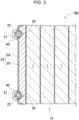
FIG. 3 is a horizontal cross-sectional view taken along line III-III ofFIG. 1 . -
FIG. 4 is a vertical cross-sectional view taken along line IV-IV ofFIG. 1 . -
FIG. 5 is an exploded perspective view of an end plate ofFIG. 1 . -
FIG. 6 is a perspective view of a power supply device according to a second exemplary embodiment. -
FIG. 7 is an exploded perspective view of an end plate of a power supply device according to a third exemplary embodiment. -
FIG. 8 is an exploded horizontal cross-sectional view of an end plate of a power supply device according to a fourth exemplary embodiment. -
FIG. 9 is an exploded plan view of an end plate according to a fifth exemplary embodiment. -
FIG. 10 is an exploded plan view of an end plate according to a sixth exemplary embodiment. -
FIG. 11 is a perspective view of a power supply device according to a seventh exemplary embodiment. -
FIG. 12 is a block diagram illustrating an example in which a power supply device is mounted on a hybrid vehicle running on an engine and a motor. -
FIG. 13 is a block diagram illustrating an example in which a power supply device is mounted on an electric vehicle running only by a motor. -
FIG. 14 is a block diagram illustrating an example applied to a power supply device for storing electricity. -
FIG. 15 is a perspective view illustrating a conventional power supply device. - One point of interest of the present invention will be described first. A metal is used for each bind bar provided for the power supply device exemplified in
PTL 1 so as to be able to withstand a relatively strong load. A metal differs in strength depending on how it receives a load, such as bending strength and tensile strength. A typical metal used as a material for each bind bar has excellent tensile strength and is characterized in that the deformation of the bind bar can be suppressed. However, a load in the shearing direction is applied to a screw fixing each bind bar, and the screw may break. On the other hand, in recent years, the amount of expansion has been increasing with the improvement of the performance of a secondary battery cell. Therefore, in the configuration exemplified inPTL 1, even if the deformation of each bind bar can be prevented, it may not be possible to prevent each screw from breaking. In recent years, such a configuration is less adopted. In consideration of these circumstances, the present inventors have studied a power supply device configured to effectively utilize the tensile strength of each bind bar, and as a result, have conceived a power supply device with a new configuration that can reduce the load on the fastening member that fixes each bind bar. - A power supply device according to an exemplary embodiment of the present invention includes a plurality of secondary battery cells having a flat rectangular parallelepiped shape, a pair of end plates covering both end faces of a battery stack in which the plurality of secondary battery cells are stacked, and a plurality of fastening members for fastening the end plates to each other. Each of the plurality of fastening members has a plate shape extending along the stacking direction of the plurality of secondary battery cells and is disposed on a corresponding one of opposite surfaces of the battery stack. Through holes are formed in both ends of each plate shape. Each of the pair of end plates includes pipe portions inserted into the through holes of a pair of fastening members disposed on opposite surfaces of the battery stack among the plurality of fastening members.
- Further, in a power supply device according to another exemplary embodiment of the present invention, each of the pair of end plates includes a plate portion having a recess that receives the pipe portion.
- In the power supply device according to an exemplary embodiment of the present invention, each of the plurality of secondary battery cells includes a package can having an opening and a sealing plate for sealing the opening of the package can. At least one of the plurality of fastening members is disposed on the surface of the sealing plate among the surfaces constituting the battery stack. With the above configuration, the sealing plate can be pressed by the fastening member.
- In the power supply device according to another exemplary embodiment of the present invention, the pipe portion has pipe holes in both end edges of the pipe portion. The power supply device further has flange bolts inserted into the through holes and the pipe holes. The flange bolt has a flange having a larger diameter than the through hole. With the above configuration, a fastening member can be fixed to an end plate while the fastening force is easily adjusted by screwing.
- In the power supply device according to another exemplary embodiment of the present invention, the pipe portion has pipe holes in both end edges of the pipe portion. The power supply device further has press-fit pins press fitted into the through holes and the pipe holes. The press-fit pin has a flange having a larger diameter than the through hole. The above configuration has an advantage of easily fixing a fastening member to the end plate without using screws.
- The outer shape of the pipe portion may be cylindrical, and the recess may be formed in a curved shape according to the side surface of the pipe portion. With the above configuration, the stress applied to the fastening member is received through the curved surfaces of the pipe portion and the plate portion to alleviate the stress concentration, and is dispersed in the plate portion, thereby stably holding and improving reliability.
- Further, the plate portion may be formed in a size capable of covering the secondary battery cell, and the recesses may be formed at right and left symmetrical positions of the plate portion.
- The plate portion and the pipe portion may be welded.
- A vehicle according to another exemplary embodiment of the present invention includes the power supply device, a running motor to which power is supplied from the power supply device, a vehicle body equipped with the power supply device and the motor, and wheels that are driven by the motor to run the vehicle body.
- Exemplary embodiments of the present invention will be described with reference to the accompanying drawings. However, the exemplary embodiments described below are examples for embodying the technical idea of the present invention, and the present invention is not specified as the following. This specification does not specify the members described in the claims as the members of the exemplary embodiments. In particular, the dimensions, materials, shapes, relative arrangements, and the like of the components described in the exemplary embodiments are not intended to limit the scope of the present invention to that alone, and are merely explanatory examples unless otherwise specified. The sizes of the members and the positional relationship between the members illustrated in each drawing may be exaggerated to clarify the explanation. In the following description, the same names and reference numerals denote the same members or members having the same quality, and a detailed description of them will be omitted as appropriate. Further, each element constituting the present invention may be configured such that a plurality of elements are composed of the same member and one member serves as a plurality of elements, or conversely, the function of one member can be implemented by a plurality of members in a shared manner.
- The power supply device according to the exemplary embodiment is used for various purposes such as a power supply mounted on an electric vehicle such as a hybrid vehicle or an electric vehicle to supply electric power to a running motor, a power supply for storing generated power of natural energy such as solar power generation or wind power generation, and a power supply for storing midnight power, and is particularly suitable as a power supply suitable for high power and high current applications.
-
FIG. 1 is a perspective view ofpower supply device 100 according to a first exemplary embodiment of the present invention,FIG. 2 is an exploded perspective view ofpower supply device 100,FIG. 3 is a horizontal cross-sectional view taken along line III - III inFIG. 1 , andFIG. 4 is a vertical cross-sectional view taken along line IV - IV inFIG. 1 .power supply device 100 illustrated inFIGS. 1 to 4 includes a plurality ofsecondary battery cells 1 having positive andnegative electrode terminals 2 andbus bars 3 that are connected toelectrode terminals 2 of the plurality ofsecondary battery cells 1 and connect the plurality ofsecondary battery cells 1 in parallel and in series. The plurality ofsecondary battery cells 1 are connected in parallel or in series via bus bars 3.Secondary battery cell 1 is a rechargeable secondary battery. Inpower supply device 100, the plurality ofsecondary battery cells 1 are connected in parallel to form a parallel battery group, and a plurality of parallel battery groups are connected in series so that a large number ofsecondary battery cells 1 are connected in parallel and in series. Inpower supply device 100 illustrated inFIGS. 1 and2 , the plurality ofsecondary battery cells 1 are staked to formbattery stack 10. Further, a pair ofend plates 20 are arranged on both end faces ofbattery stack 10. The ends offastening members 30 are fixed toend plates 20 to fix stackedsecondary battery cells 1 to a pressurized state. -
Secondary battery cell 1 is a square battery whose wide main surface has a quadrangular outer shape and which is thinner than the width. Further,secondary battery cell 1 is a secondary battery that can be charged and discharged, and is a lithium ion secondary battery. However, the present invention does not specify the secondary battery cell as the square battery, nor specifies the secondary battery cell as the lithium ion secondary battery. As the secondary battery cell, all rechargeable batteries can be used, including, for example, a non-aqueous electrolyte secondary battery and a nickel water secondary battery cell other than the lithium ion secondary battery. - As illustrated in
FIG. 2 , insecondary battery cell 1, an electrode body obtained by stacking positive and negative electrode plates is housed in package can 1a which is filled with an electrolytic solution and airtightly sealed. Package can 1a is formed into a square cylinder that closes the bottom, and the upper opening is airtightly closed by sealingplate 1b formed from a metal plate. Package can 1a is formed by deep-drawing a metal plate such as aluminum or an aluminum alloy. Like package can 1a, sealingplate 1b is formed from a metal plate such as aluminum or an aluminum alloy.Sealing plate 1b is inserted into the opening of package can 1a, and the boundary between the outer periphery of sealingplate 1b and the inner periphery of package can 1a is irradiated with a laser beam to airtightlyfix sealing plate 1b to package can 1a by laser welding. -
Secondary battery cell 1 has sealingplate 1b, which is the top surface, asterminal surface 1X. Positive andnegative electrode terminals 2 are fixed to both ends ofterminal surface 1X.Electrode terminal 2 has a columnar protruding portion. However, the protruding portion need not be necessarily be cylindrical, and may be polygonal or elliptical. - The positions of positive and
negative electrode terminals 2 fixed to sealingplate 1b ofsecondary battery cell 1 are set such that the positive electrode and the negative electrode are symmetrical. As a result,secondary battery cells 1 are flipped horizontally and stacked, and positive andnegative electrode terminals 2 that are adjacent and close to each other are connected throughbus bars 3, so that adjacentsecondary battery cells 1 can be connected in series. - The plurality of
secondary battery cells 1 are stacked to formbattery stack 10 such that the thickness direction of eachsecondary battery cell 1 is the stacking direction. Inbattery stack 10, a plurality ofsecondary battery cells 1 are stacked such thatterminal surface 1X provided with positive andnegative electrode terminals 2 and sealingplate 1b inFIG. 2 are flush with each other. -
Battery stack 10 may have an insulating spacer interposed between the secondary battery cells stacked adjacent to each other. The insulating spacer is made of an insulating material such as a resin and is formed in a thin plate shape or a sheet shape. The insulating spacer has a plate shape having a size almost equal to the facing surface of the secondary battery cell. The insulating spacers can be stacked between the secondary battery cells adjacent to each other to insulate the adjacent secondary battery cells from each other. - As a spacer disposed between the adjacent secondary battery cells, a spacer having a shape that forms a flow path of a cooling gas between the secondary battery cell and the spacer can also be used. Further, the surface of the secondary battery cell can be coated with an insulating material. For example, a shrink tube such as PET resin is heat-welded to the surface of the package can except for the electrode portions of the secondary battery cell. In this case, the insulating spacer may be omitted. Further, in a power supply device in which a plurality of secondary battery cells are connected in multiple parallel and multiple series, the secondary battery cells connected in series are insulated by interposing an insulating spacer between the secondary battery cells, whereas, because there is no voltage difference between the adjacent package cans of the secondary battery cells connected in parallel, the insulating spacer between the secondary battery cells can be omitted.
- Further, in
power supply device 100 illustrated inFIG. 2 ,end plates 20 are disposed on both end faces ofbattery stack 10. An end face spacer may be interposed between the end plate and the battery stack to insulate them. The insulating spacer is also made of an insulating material such as a resin and formed in a thin plate shape or a sheet shape. - In
battery stack 10,metal bus bars 3 are connected to positive andnegative electrode terminals 2 of adjacentsecondary battery cells 1, and the plurality ofsecondary battery cells 1 are connected in parallel and in series via bus bars 3. Inbattery stack 10, a plurality ofsecondary battery cells 1 connected in parallel to each other to form parallel battery groups are stacked such that positive andnegative electrode terminals 2 provided at both ends of eachterminal surface 1X are located in the same direction laterally, whereassecondary battery cells 1 that form parallel battery groups connected in series to each other are stacked such that positive andnegative electrode terminals 2 provided at both ends ofterminal surfaces 1X are located in laterally opposite directions. Here, inpower supply device 100 according to the first exemplary embodiment illustrated inFIGS. 1 to 2 , twelvesecondary battery cells 1 are laminated in the thickness direction to form abattery stack 10, and foursecondary battery cells 1 are connected in parallel to form a parallel battery group, and three sets of parallel battery groups are connected in series to connect twelvesecondary battery cells 1 in four parallel three series. Therefore, inbattery stack 10 illustrated inFIG. 2 , foursecondary battery cells 1 constituting the parallel battery group are stacked so as to set positive andnegative electrode terminals 2 in the same direction laterally, and three sets of parallel battery groups each constituted by foursecondary battery cells 1 stacked in the same direction are stacked so as to set positive andnegative electrode terminals 2 alternately in opposite directions. However, the present invention does not specify a number of secondary battery cells constituting the battery stack and the connection state of the battery cells. The number of secondary battery cells constituting the battery stack and the connection state of the battery cells can be variously changed as well as in other exemplary embodiments described later. - In
power supply device 100 according to the first exemplary embodiment, inbattery stack 10 obtained by stacking a plurality ofsecondary battery cells 1 on each other,electrode terminals 2 of adjacentsecondary battery cells 1 are connected to each other throughbus bar 3, and the plurality ofsecondary battery cells 1 are connected in parallel and in series. -
Bus bar 3 is manufactured by cutting and processing a metal plate into a predetermined shape. As a metal plate formingbus bar 3, a metal having a low electric resistance and a small weight, such as a plate made of an aluminum, copper plate, or their alloy, can be used. However, as a metal plate ofbus bar 3, other metals or their alloys, which have a low electric resistance and a small weight, can also be used. Further, bus bar holders may be disposed betweenbattery stack 10 and bus bars 3. A plurality of bus bars can be disposed at fixed positions on the upper surface of the battery stack while the plurality of bus bars are insulated from each other and the terminal surfaces of the secondary battery cells are insulated from the bus bars by using the bus holders. - As illustrated in
FIGS. 1 to 4 ,end plates 20 are disposed at both ends ofbattery stack 10 and are fastened viafastening members 30 disposed along both side surfaces ofbattery stack 10.End plates 20 are both ends ofbattery stack 10 in the stacking direction ofsecondary battery cell 1, and are disposed outside the end face spacers tosandwich battery stack 10 from both ends. - Both ends of fastening
member 30 are fixed toend plates 20 disposed on both end faces ofbattery stack 10.End plate 20 is fixed by a plurality offastening members 30, andbattery stack 10 is fastened in the stacking direction. Fasteningmembers 30 are metal plates each having a predetermined width and a predetermined thickness along the upper surface ofbattery stack 10, and are disposed so as to face the upper and lower surfaces ofbattery stack 10. A metal plate such as an iron plate, preferably a steel plate, can be used for fasteningmember 30. Fasteningmember 30 made of a metal plate is bent by press molding or the like to form a predetermined shape. - As illustrated in
FIGS. 1 to 4 ,fastening member 30 is formed in a plate shape extending in the stacking direction ofbattery stack 10. In other words, fasteningmember 30 is formed in the shape of a flat plate with no bent edges. By fixing the end edges offastening members 30 having such a configuration to endplates 20, it is possible to increase the resistance to the shear stress generated whensecondary battery cells 1 expand. That is, a channel shapedbent bind bar 930 used for conventionalpower supply device 900 illustrated inFIG. 15 may be broken at a bent portion because the shear stress is likely to be concentrated on the bent portion. Accordingly, by formingfastening member 30 in a flat plate shape without providing such a bent portion, it is possible to avoid the occurrence of a portion where the stress is likely to be concentrated and to receive the stress byentire fastening member 30, thereby improving the resistance. - Through
holes 32 are formed in both ends of plate-shapedfastening member 30. Fasteningmembers 30 are disposed on opposite surfaces ofbattery stack 10, and throughholes 32 are disposed coaxially. - The fastening member having the above structure does not have a processed portion such as a portion formed by bending that increases the dimensional tolerance, and hence can be molded with high dimensional accuracy. Accordingly, when assembling the power supply device, making holes for forming through
holes 32 in accordance with the dimensions of the battery stack pressurized at a predetermined pressure can reduce variations in compressive force applied from the fastening members. - On the other hand,
end plate 20 is composed ofpipe portions 21 andplate portion 23.Pipe portion 21 has apipe hole 22 in the end edge. As illustrated in the vertical cross-sectional view ofFIG. 4 ,pipe hole 22 can be a through hole extending throughpipe portion 21. This makes it possible to formpipe portion 21 into a hollow pipe to reduce the weight and cost. Alternatively, the pipe portion may be formed into a solid columnar shape, and pipe holes may be formed in the end faces at a constant depth. By using a solid pipe portion, the strength of the pipe portion can be increased and the rigidity against stress can be increased. - As illustrated in the horizontal cross-sectional view of
FIG. 3 ,plate portion 23 hasrecesses 26 for receivingpipe portions 21 on the right and left.Plate portion 23 has the pair ofpipe portions 21 coupled to right and leftrecesses 26, respectively. In this state,pipe hole 22 ofpipe portion 21 is fixed so as to coincide with throughhole 32 of fasteningmember 30. With this configuration, the stress received bypipe portion 21 is transmitted to plateportion 23, so that the stress can be dispersed by being received over a wide area. That is, by avoiding the concentration of the stress, the rigidity can be increased, the durability can be improved, and the fastening force ofbattery stack 10 can be stably maintained for a long period of time. In particular, as described above, making each fasteningmember 30 plate-shaped without any bent portion prevents the stress from concentrating on a specific portion of fasteningmember 30, such as a bent portion. In addition, makingpipe portion 21 ofend plate 20 fixed to fasteningmember 30 also receive the stress can prevent the occurrence of the shear stress and stably maintain the fastening force ofbattery stack 10 for a long period of time. - Fastening
members 30 are disposed on opposite surfaces ofbattery stack 10. In the example illustrated inFIGS. 1 to 4 ,fastening members 30 are disposed on the upper and lower surfaces ofbattery stack 10. In this case, as illustrated inFIG. 1 and the like,fastening member 30 is displaced from the position ofelectrode terminal 2 of eachsecondary battery cell 1 so as to exposeelectrode terminal 2. Further, in this configuration, by disposingfastening member 30 on the surface of sealingplate 1b ofsecondary battery cell 1,fastening member 30 can press the upper surface of sealingplate 1b. -
Plate portion 23 ofend plate 20 has a quadrangular outer shape, and is disposed so as to face the end face ofbattery stack 10.Plate portion 23 illustrated inFIGS. 1 to 4 has an outer shape substantially equal to the outer shape ofsecondary battery cell 1. That is,plate portion 23 illustrated inFIGS. 1 to 4 has a width in the lateral direction substantially equal to the width ofsecondary battery cell 1 and a height in the vertical direction substantially equal to the height ofsecondary battery cell 1. In this specification, the vertical direction means the vertical direction in the accompanying drawings, and the lateral direction means the lateral direction in the accompanying drawings, which means the horizontal direction orthogonal to the stacking direction of the batteries. - On the other hand,
pipe portion 21 is designed to have a length substantially equal to or slightly larger than the height ofplate portion 23. Accordingly,pipe hole 22 in the end face ofpipe portion 21 can be fixed to fasteningmember 30 so as to coincide with or slightly protrude from the upper end ofplate portion 23. If the through hole of the each fastening member is made larger than the outer shape of the pipe portion, the pipe portion can be easily inserted through the through hole. However, from the viewpoint of strength, the outer shape of the pipe portion is preferably nearly equal to the size of the through hole of the fastening member. -
Pipe portion 21 preferably has a columnar outer shape. Further,recess 26 ofplate portion 23 is formed in a curved shape in accordance with the columnar side surface ofpipe portion 21. Formingconcave portion 26 into a curved portion will enhance the effect of relaxing the stress concentration by receiving the stress applied to fasteningmember 30 through the curved surfaces ofpipe portion 21 andplate portion 23. On the contrary, ifpipe portion 21 is formed into a prismatic shape, the stress may concentrate on the bent portion ofrecess 26 ofplate portion 23 that receivespipe portion 21. This may cause fracture. In contrast to this, by receiving the stress through curved surfaces, the dispersion effect is enhanced by avoiding the occurrence of such stress concentration points. This can improve the reliability. -
Pipe hole 22 formed in the end face ofpipe portion 21 can be a screw hole having a thread groove on the inner surface. In the example illustrated inFIG. 5 ,fastening member 30 andpipe portion 21 are threadably engaged with each other withflange bolts 40 that threadably engages throughhole 32 withpipe hole 22. Using such threadable engagement can fixfastening member 30 toend plate 20 while easily adjusting the fastening force. - However, the present invention does not limit the fixing structure of the fastening member and
pipe portion 21 to threadable engagement. For example, pins or rivets can be press-fitted, swaged, welded, or the like. For example, in the power supply device illustrated inFIG. 6 as a second exemplary embodiment, press-fit pin 42 is fixed by being driven into throughhole 32 andpipe hole 22. This makes it possible to fixfastening member 30 toend plate 20B in a process simpler than threadable engagement. - Through
hole 32 may have the same size as the outer diameter ofcylindrical pipe portion 21. In this case,fastening member 30 and the upper surface ofpipe portion 21 are designed to be flush with each other withpipe portion 21 inserted in throughhole 32. For example, the length ofpipe portion 21 is designed to be larger than the height ofplate portion 23 by the thickness of twofastening members 30. This makes it possible to firmly fixpipe portion 21 andfastening members 30 to each other by inserting the top and bottom ofpipe portion 21 intoholes 32, making the end faces ofpipe portion 21 flush withfastening members 30, and fixingflange bolts 40 or press-fit pins 42 topipe hole 22. - It is preferable that
plate portion 23 andpipe portion 21 are fixed in advance. In the example illustrated inFIG. 5 ,plate portion 23 andpipe portion 21 are welded. MIG welding or the like can be used for welding. - However,
plate portions 23 and the pipe portions need not always be fixed to each other. For example, according to a third exemplary embodiment,pipe portion 21 may be coupled to recess 26 as in the case ofend plate 20C of the power supply device illustrated in the exploded perspective view ofFIG. 7 . Fixingpipe portions 21 tofastening members 30 will inevitably clampplate portions 23 withpipe portions 21 from both the right and left sides of the battery stack, thereby firmly couplingpipe portions 21 andplate portions 23. -
Plate portion 23 is formed by combiningfirst plate 24 obtained by bending a metal plate andsecond plate 25 which has a flat plate shape thicker thanfirst plate 24 and hasrecess 26 formed in one surface. Bothfirst plate 24 andsecond plate 25 can be formed by press molding or the like. Alternatively,second plate 25 may be formed by cutting, casting, or the like.First plate 24 andsecond plate 25 are made of highly rigid metal such as steel use stainless (SUS) or iron. Further, it is preferable thatfirst plate 24 andsecond plate 25 are previously joined and fixed. However,first plate 24 andsecond plate 25 may not be fixed and may be coupled to each other by being fixed to fasteningmember 30 as described above as in the case ofend plate 20D according to a fourth exemplary embodiment illustrated inFIG. 8 . - Each plate portion may be integrally formed in advance without being divided into the first plate and the second plate.
FIG. 9 illustrates such an example as plate portion 23' of a power supply device according to a fifth exemplary embodiment. Plate portion 23' ofend plate 20E is made of a single metal plate, which has the advantage of saving the trouble of joining the first plate and the second plate. - Each plate portion may be formed by bending a single metal plate. The cross-sectional view of
FIG. 10 illustrates such an example as an end plate for a power supply device according to a sixth exemplary embodiment.Plate portion 23E can greatly reduce the weight ofend plate 20F as compared with, for example, the first exemplary embodiment, and can also reduce the member cost. Further,end plate 20F can be easily deformed. Accordingly, when the secondary battery cell expands,end plate 20F itself deforms to absorb displacement due to the expansion. - The above end plate has a plurality of
pipe portions 21 extending from the top to the bottom and fixed tofastening members 30. In the example illustrated inFIG. 1 and the like,pipe portions 21 are disposed on the right and left sides ofplate portion 23, and the pair ofpipe portions 21 are respectively fixed tofastening members 30. As a result, the stress at the time of expansion of the secondary battery cell is dispersed and received by right and leftpipe portions 21, and is transmitted to plateportion 23, thereby counteracting the stress over a wide area. Preferably, recesses 26 are formed at symmetrical positions on the right and left ofplate portion 23. As a result, the stress received by right and leftpipe portions 21 can be evenly dispersed byplate portion 23, thereby allowing the plate portion to exhibit resistance characteristics in a well-balanced manner. - In the above example, two
pipe portions 21 are provided on eachend plate 20 and fastened to each of the upper and lower surfaces ofbattery stack 10 with twofastening members 30. However, the present invention is not limited to this configuration, and three or more pipe portions and fastening members may be disposed. As an example,power supply device 700 according to a seventh exemplary embodiment is illustrated in the perspective view ofFIG. 11 .End plate 20G illustrated inFIG. 11 has threepipe portions 21 and threefastening members 30 disposed onplate portion 23G. By increasing a number of fastening members in this way, the fastening force of the battery stack can be further increased. In addition to increasing the number of fastening members, the fastening force can be adjusted by changing the width of the fastening members. However, if the number of fastening members or the width increases, the area covering the sealing plate of the secondary battery cell increases, which may hinder the exposure of the electrode terminals provided on the sealing plate. Therefore, the number, width, and placement positions offastening members 30 are adjusted in accordance with the capacity of the secondary battery cell, the expected expansion amount, the required fastening force, and the positions of the electrode terminals. - The above power supply device can be used as a vehicle-mounted power supply. As a vehicle equipped with a power supply device, an electrically driven vehicle such as a hybrid vehicle or a plug-in hybrid vehicle that runs on both an engine and a motor, or an electric vehicle that runs only on a motor can be used. The power supply device is used as a power supply for these vehicles. Large-capacity, high-output
power supply device 100 will be exemplified, which is constructed by connecting a large number of power supply devices, each described above, in series or in parallel in order to obtain electric power for driving a vehicle and adding a necessary control circuit. -
FIG. 12 illustrates an example in which the power supply device is mounted on a hybrid vehicle running on both an engine and a motor. Vehicle HV equipped with the power supply device illustrated inFIG. 12 includesvehicle body 91,engine 96 and runningmotor 93 on whichvehicle body 91 runs,wheels 97 driven byengine 96 and runningmotor 93,power supply device 100 that supplies electric power tomotor 93, andgenerator 94 that charges the batteries ofpower supply device 100.Power supply device 100 is connected tomotor 93 andgenerator 94 via DC/AC inverter 95. Vehicle HV runs on bothmotor 93 andengine 96 while charging and discharging the batteries ofpower supply device 100.Motor 93 is driven to run the vehicle in a region where the engine efficiency is low, for example, at the time of accelerating or traveling at a low speed.Motor 93 is driven by being supplied with electric power frompower supply device 100.Generator 94 is driven byengine 96 or by regenerative braking upon braking of the vehicle to charge the batteries ofpower supply device 100. As illustrated inFIG. 12 , vehicle HV may be provided with chargingplug 98 for chargingpower supply device 100. By connecting chargingplug 98 to an external power supply,power supply device 100 can be charged. -
FIG. 13 illustrates an example in which the power supply device is mounted on an electric vehicle that travels only on a motor. Vehicle EV equipped with the power supply device illustrated inFIG. 13 includesvehicle body 91, runningmotor 93 on whichvehicle body 91 runs,wheels 97 driven by runningmotor 93,power supply device 100 that supplies electric power tomotor 93, andgenerator 94 that charges the batteries ofpower supply device 100.Power supply device 100 is connected tomotor 93 andgenerator 94 via DC/AC inverter 95.Motor 93 is driven by being supplied with electric power frompower supply device 100.Generator 94 is driven by the energy used for regenerative braking of vehicle EV to charge the batteries ofpower supply device 100. In addition, vehicle EV is equipped with chargingplug 98.Power supply device 100 can be charged by connecting chargingplug 98 to an external power supply. - The present invention does not specify the use of the power supply device as the power supply of the motor that runs the vehicle. The power supply device according to each exemplary embodiment can also be used as a power supply for an electric storage system that charges and stores electricity in batteries with electric power generated by solar power generation, wind power generation, or the like.
FIG. 14 illustrates an electric storage system in which the batteries ofpower supply device 100 are charged by solar cells to store electricity. As illustrated inFIG. 14 , the electric storage system illustrated inFIG. 14 charges the batteries ofpower supply device 100 with electric power generated bysolar cell 82 disposed on the roof or roof terrace of building 81 such as a house or factory. Furthermore, this electric storage system supplies the power stored inpower supply device 100 to load 83 via DC/AC inverter 85. - Although not illustrated, the power supply device can also be used as the power supply of an electric storage system that charges and stores electricity in a battery by using midnight power at night. The power supply device that is charged with midnight power can be charged with midnight power that is the surplus power of a power plant, outputs power during the daytime when the power load increases, and limits the peak power during the daytime to a small value. The power supply device can also be used as a power supply that is charged with both the output of a solar cell and midnight power. This power supply device can effectively store both electric power generated by a solar cell and midnight electric power, and can efficiently store electricity in consideration of weather and power consumption.
- The electric storage system as described above can be suitably used for applications such as a backup power supply device that can be installed in the rack of a computer server, a backup power supply device for a wireless base station for mobile phones or the like, an electric storage power supply for a home or a factory, a street light power supply or the like, an electric storage device combined with a solar cell, and a backup power supply for traffic lights and traffic indicators for roads.
- The power supply device and the vehicle provided with the power supply device according to the present invention can be suitably used as a power supply for a large current used for the power supply of a motor for driving an electrically driven vehicle such as a hybrid vehicle, a fuel cell vehicle, an electric vehicle, or an electric motorcycle. For example, the above devices include a power supply device for a plug-in hybrid electric vehicle and a hybrid electric vehicle that can switch between the EV running mode and the HEV running mode, and an electric vehicle. The above devices can be used as appropriate for applications such as a backup power supply device that can be installed in the rack of a computer server, a backup power supply device for a wireless base station for mobile phones or the like, an electric storage power supply for a home or a factory, a street light power supply or the like, an electric storage device combined with a solar cell, and a backup power supply for traffic lights.
-
- 100, 700
- power supply device
- 1
- secondary battery cell
- 1X
- terminal surface
- 1a
- package can
- 1b
- sealing plate
- 2
- electrode terminal
- 3
- bus bar
- 10
- battery stack
- 20, 20B, 20C, 20D, 20E, 20F, 20G
- end plate
- 21
- pipe portion
- 22
- pipe hole
- 23, 23', 23E, 23G
- plate portion
- 24
- first plate
- 25
- second plate
- 26
- recess
- 30
- fastening member
- 32
- through hole
- 40
- flange bolt
- 42
- press-fit pin
- 81
- building
- 82
- solar cell
- 83
- load
- 85
- DC/AC inverter
- 91
- vehicle body
- 93
- motor
- 94
- generator
- 95
- DC/AC inverter
- 96
- engine
- 97
- wheel
- 98
- charging plug
- 900
- power supply device
- 901
- secondary battery cell
- 920
- end plate
- 930
- bind bar
- HV
- vehicle
- EV
- vehicle
Claims (8)
- A power supply device (100) comprising:a plurality of secondary battery cells (1) each having a flat rectangular parallelepiped shape;a pair of end plates (20) covering both end faces of a battery stack (10) having the plurality of secondary battery cells (1) stacked on each other; anda plurality of fastening members (30) configured to fasten the end plates (20) to each other, whereineach of the plurality of fastening members (30) comprises a metal plate without bent edges having a plate shape extending along a stacking direction of the plurality of secondary battery cells (1), the plurality of fastening members (30) are respectively disposed on opposite surfaces of the battery stack (10), and the plurality of fastening members (30) each have a through hole (32) in each of both ends of the plate shape, andeach of the pair of end plates (20) comprises a plate portion (23) having a recess (26) that receives a pipe portion (21) inserted into the through hole (32) of each of a pair of fastening members among the plurality of fastening members (30), the pair of fastening members being disposed on opposite surfaces of the battery stack (10), wherein the pipe portion (21) has a pipe hole (22) in each of both end edges of the pipe portion (21).
- The power supply device (100) according to claim 1, whereineach of the plurality of secondary battery cells (1) comprises a package can (1a) having an opening and a sealing plate (1b) that seals the opening of the package can (1a), andat least one of the plurality of fastening members (30) is disposed on a surface of the sealing plate (1b) among a surfaces constituting the battery stack (10).
- The power supply device (100) according to any one of claims 1 to 2, wherein
the power supply device (100) further includes flange bolt (40) inserted into the through hole (32) and the pipe hole (22), the flange bolt (40) having a flange having a larger diameter than the through hole (32). - The power supply device (100) according to any one of claims 1 to 2, wherein
the power supply device (100) further includes press-fit pin (42) press fitted into the through hole (32) and the pipe hole (22), the press-fit pin (42) having a flange having a larger diameter than the through hole (32). - The power supply device (100) according to any one of claims 1 to 4, whereinthe pipe portion (21) has a columnar outer shape, andthe recess (26) is formed in a curved shape in accordance with a side surface of the pipe portion (21).
- The power supply device (100) according to any one of claims 1 to 5, whereinthe plate portion (23) is formed in a size capable of covering one of the secondary battery cells (1), andthe recess (26) is formed at each of right and left symmetrical positions of the plate portion (23).
- The power supply device (100) according to any one of claims 1 to 6, wherein the plate portion (23) and the pipe portion (21) are welded to each other.
- A vehicle (HV, EV) comprising the power supply device (100) according to any one of claims 1 to 7, the vehicle comprising:the power supply device (100);a running motor (93) to which power is supplied from the power supply device (100);a vehicle body (91) equipped with the power supply device (100) and the running motor (93); anda wheel (97) that is driven by the running motor (93) to run the vehicle body (91).
Applications Claiming Priority (2)
| Application Number | Priority Date | Filing Date | Title |
|---|---|---|---|
| JP2018144244 | 2018-07-31 | ||
| PCT/JP2019/029337 WO2020026962A1 (en) | 2018-07-31 | 2019-07-26 | Power supply device and vehicle equipped with same |
Publications (3)
| Publication Number | Publication Date |
|---|---|
| EP3832750A1 EP3832750A1 (en) | 2021-06-09 |
| EP3832750A4 EP3832750A4 (en) | 2021-08-25 |
| EP3832750B1 true EP3832750B1 (en) | 2024-07-10 |
Family
ID=69232586
Family Applications (1)
| Application Number | Title | Priority Date | Filing Date |
|---|---|---|---|
| EP19843346.8A Active EP3832750B1 (en) | 2018-07-31 | 2019-07-26 | Power supply device and vehicle equipped with same |
Country Status (5)
| Country | Link |
|---|---|
| US (1) | US11870087B2 (en) |
| EP (1) | EP3832750B1 (en) |
| JP (1) | JP7374901B2 (en) |
| CN (1) | CN112514147B (en) |
| WO (1) | WO2020026962A1 (en) |
Families Citing this family (5)
| Publication number | Priority date | Publication date | Assignee | Title |
|---|---|---|---|---|
| WO2020257414A1 (en) * | 2019-06-21 | 2020-12-24 | Sion Power Corporation | Methods, systems, and devices for applying forces to electrochemical devices |
| JP7317760B2 (en) * | 2020-03-31 | 2023-07-31 | トヨタ自動車株式会社 | BATTERY MANUFACTURING METHOD AND BATTERY |
| KR102877552B1 (en) * | 2020-10-06 | 2025-10-27 | 주식회사 엘지에너지솔루션 | Battery apparatus and method for measuring cell voltage |
| CA3222391A1 (en) * | 2021-08-05 | 2023-02-09 | Kwan-Hee Lee | Electrode assembly, secondary battery, battery pack and vehicle including the same |
| JP7559801B2 (en) * | 2022-06-02 | 2024-10-02 | トヨタ自動車株式会社 | Power storage device |
Family Cites Families (22)
| Publication number | Priority date | Publication date | Assignee | Title |
|---|---|---|---|---|
| JP3271494B2 (en) | 1995-10-24 | 2002-04-02 | 松下電器産業株式会社 | Stacked sealed alkaline storage battery |
| JP4776886B2 (en) * | 2004-03-22 | 2011-09-21 | 本田技研工業株式会社 | Fuel cell stack structure |
| US7396262B2 (en) * | 2004-12-10 | 2008-07-08 | Cooper Technologies Company | Sealed compact power distribution module |
| US10014508B2 (en) * | 2006-11-27 | 2018-07-03 | Lg Chem, Ltd. | Battery module assembly |
| JP2008277016A (en) * | 2007-04-26 | 2008-11-13 | Toyota Motor Corp | Fuel cell stack, stack assembly |
| JP5252836B2 (en) * | 2007-05-29 | 2013-07-31 | 三洋電機株式会社 | Pack battery |
| US9203065B2 (en) * | 2010-08-10 | 2015-12-01 | Samsung Sdi Co., Ltd. | Battery module |
| JP5243507B2 (en) * | 2010-09-14 | 2013-07-24 | 本田技研工業株式会社 | Battery module |
| WO2012043594A1 (en) * | 2010-09-30 | 2012-04-05 | 三洋電機株式会社 | Assembled battery and vehicle provided with same |
| JP5484403B2 (en) * | 2011-06-08 | 2014-05-07 | 本田技研工業株式会社 | Battery module |
| WO2013031614A1 (en) * | 2011-08-26 | 2013-03-07 | 三洋電機株式会社 | Power supply device, vehicle provided with same, and power storage device |
| US9634302B2 (en) * | 2011-11-18 | 2017-04-25 | Hitachi Automotive Systems, Ltd. | Secondary battery module |
| JP6223978B2 (en) | 2012-08-09 | 2017-11-01 | 三洋電機株式会社 | Power supply device, electric vehicle including the same, and power storage device |
| KR101678531B1 (en) * | 2013-01-31 | 2016-11-22 | 삼성에스디아이 주식회사 | Battery module having clinching coupling |
| US9537125B2 (en) * | 2013-06-27 | 2017-01-03 | Samsung Sdi Co., Ltd. | Battery module |
| KR101688489B1 (en) * | 2013-11-19 | 2016-12-21 | 삼성에스디아이 주식회사 | Battery module |
| KR102468334B1 (en) * | 2015-11-04 | 2022-11-16 | 삼성에스디아이 주식회사 | Rechargeable battery module |
| KR102092268B1 (en) * | 2015-11-30 | 2020-03-23 | 주식회사 엘지화학 | Clamping member and battery module using thereof |
| JP2017157407A (en) * | 2016-03-01 | 2017-09-07 | 日立オートモティブシステムズ株式会社 | Secondary battery module |
| CN206250253U (en) * | 2016-12-27 | 2017-06-13 | 宁德时代新能源科技股份有限公司 | Battery modules end plate and battery modules |
| CN206727133U (en) * | 2017-05-15 | 2017-12-08 | 宁德时代新能源科技股份有限公司 | Battery modules |
| JP6706598B2 (en) * | 2017-07-06 | 2020-06-10 | 本田技研工業株式会社 | Battery module |
-
2019
- 2019-07-26 US US17/262,251 patent/US11870087B2/en active Active
- 2019-07-26 JP JP2020533484A patent/JP7374901B2/en active Active
- 2019-07-26 EP EP19843346.8A patent/EP3832750B1/en active Active
- 2019-07-26 WO PCT/JP2019/029337 patent/WO2020026962A1/en not_active Ceased
- 2019-07-26 CN CN201980051021.7A patent/CN112514147B/en active Active
Also Published As
| Publication number | Publication date |
|---|---|
| EP3832750A4 (en) | 2021-08-25 |
| JPWO2020026962A1 (en) | 2021-08-02 |
| US20210351472A1 (en) | 2021-11-11 |
| CN112514147A (en) | 2021-03-16 |
| WO2020026962A1 (en) | 2020-02-06 |
| EP3832750A1 (en) | 2021-06-09 |
| JP7374901B2 (en) | 2023-11-07 |
| CN112514147B (en) | 2023-01-31 |
| US11870087B2 (en) | 2024-01-09 |
Similar Documents
| Publication | Publication Date | Title |
|---|---|---|
| EP3832750B1 (en) | Power supply device and vehicle equipped with same | |
| EP3855526B1 (en) | Power supply device, vehicle having power supply device, and power storage device | |
| US11817593B2 (en) | Power supply device and vehicle provided with power supply device | |
| US11962026B2 (en) | Power supply device and vehicle equipped therewith | |
| CN112272884B (en) | Battery pack and vehicle provided with same | |
| EP3832752B1 (en) | Power supply device and vehicle having the same | |
| US12531306B2 (en) | Power supply device, electric vehicle using same, and power storage device | |
| CN115053386B (en) | Power supply device, vehicle provided with same, and power storage device | |
| WO2020194937A1 (en) | Power supply device, and electric vehicle and electrical storage device each equipped with same | |
| EP4131561A1 (en) | Power supply device, vehicle provided with same, and power storage device | |
| CN113646956B (en) | Power supply device, electric vehicle using the same, power storage device, fastening member for power supply device, manufacturing method of power supply device, and manufacturing method of fastening member for power supply device | |
| US12155081B2 (en) | Power supply device, electric vehicle and power storage device provided with said power supply device, and fastening member for power supply device | |
| WO2020194930A1 (en) | Power supply device, electric vehicle using same, and power storage device | |
| EP4131564A1 (en) | Power source device, and vehicle and power storage device each equipped with same | |
| WO2021157139A1 (en) | Power supply device, electric vehicle using same, and power storage device | |
| JP2022123152A (en) | Power supply device and electric vehicle with power supply device and power storage device |
Legal Events
| Date | Code | Title | Description |
|---|---|---|---|
| STAA | Information on the status of an ep patent application or granted ep patent |
Free format text: STATUS: THE INTERNATIONAL PUBLICATION HAS BEEN MADE |
|
| PUAI | Public reference made under article 153(3) epc to a published international application that has entered the european phase |
Free format text: ORIGINAL CODE: 0009012 |
|
| STAA | Information on the status of an ep patent application or granted ep patent |
Free format text: STATUS: REQUEST FOR EXAMINATION WAS MADE |
|
| 17P | Request for examination filed |
Effective date: 20210120 |
|
| AK | Designated contracting states |
Kind code of ref document: A1 Designated state(s): AL AT BE BG CH CY CZ DE DK EE ES FI FR GB GR HR HU IE IS IT LI LT LU LV MC MK MT NL NO PL PT RO RS SE SI SK SM TR |
|
| A4 | Supplementary search report drawn up and despatched |
Effective date: 20210726 |
|
| RIC1 | Information provided on ipc code assigned before grant |
Ipc: H01M 50/209 20210101AFI20210720BHEP Ipc: H01M 50/20 20210101ALI20210720BHEP |
|
| DAV | Request for validation of the european patent (deleted) | ||
| DAX | Request for extension of the european patent (deleted) | ||
| REG | Reference to a national code |
Ref country code: DE Ref legal event code: R079 Free format text: PREVIOUS MAIN CLASS: H01M0002100000 Ipc: H01M0050209000 Ref country code: DE Ref legal event code: R079 Ref document number: 602019055095 Country of ref document: DE Free format text: PREVIOUS MAIN CLASS: H01M0002100000 Ipc: H01M0050209000 |
|
| GRAP | Despatch of communication of intention to grant a patent |
Free format text: ORIGINAL CODE: EPIDOSNIGR1 |
|
| STAA | Information on the status of an ep patent application or granted ep patent |
Free format text: STATUS: GRANT OF PATENT IS INTENDED |
|
| RIC1 | Information provided on ipc code assigned before grant |
Ipc: H01M 50/289 20210101ALI20240307BHEP Ipc: H01M 50/264 20210101ALI20240307BHEP Ipc: H01M 50/249 20210101ALI20240307BHEP Ipc: H01M 10/04 20060101ALI20240307BHEP Ipc: H01M 50/209 20210101AFI20240307BHEP |
|
| INTG | Intention to grant announced |
Effective date: 20240328 |
|
| GRAS | Grant fee paid |
Free format text: ORIGINAL CODE: EPIDOSNIGR3 |
|
| GRAA | (expected) grant |
Free format text: ORIGINAL CODE: 0009210 |
|
| STAA | Information on the status of an ep patent application or granted ep patent |
Free format text: STATUS: THE PATENT HAS BEEN GRANTED |
|
| AK | Designated contracting states |
Kind code of ref document: B1 Designated state(s): AL AT BE BG CH CY CZ DE DK EE ES FI FR GB GR HR HU IE IS IT LI LT LU LV MC MK MT NL NO PL PT RO RS SE SI SK SM TR |
|
| REG | Reference to a national code |
Ref country code: CH Ref legal event code: EP |
|
| REG | Reference to a national code |
Ref country code: DE Ref legal event code: R096 Ref document number: 602019055095 Country of ref document: DE |
|
| REG | Reference to a national code |
Ref country code: LT Ref legal event code: MG9D |
|
| REG | Reference to a national code |
Ref country code: NL Ref legal event code: MP Effective date: 20240710 |
|
| PG25 | Lapsed in a contracting state [announced via postgrant information from national office to epo] |
Ref country code: PT Free format text: LAPSE BECAUSE OF FAILURE TO SUBMIT A TRANSLATION OF THE DESCRIPTION OR TO PAY THE FEE WITHIN THE PRESCRIBED TIME-LIMIT Effective date: 20241111 |
|
| REG | Reference to a national code |
Ref country code: AT Ref legal event code: MK05 Ref document number: 1702860 Country of ref document: AT Kind code of ref document: T Effective date: 20240710 |
|
| PG25 | Lapsed in a contracting state [announced via postgrant information from national office to epo] |
Ref country code: NL Free format text: LAPSE BECAUSE OF FAILURE TO SUBMIT A TRANSLATION OF THE DESCRIPTION OR TO PAY THE FEE WITHIN THE PRESCRIBED TIME-LIMIT Effective date: 20240710 |
|
| PG25 | Lapsed in a contracting state [announced via postgrant information from national office to epo] |
Ref country code: PT Free format text: LAPSE BECAUSE OF FAILURE TO SUBMIT A TRANSLATION OF THE DESCRIPTION OR TO PAY THE FEE WITHIN THE PRESCRIBED TIME-LIMIT Effective date: 20241111 Ref country code: NL Free format text: LAPSE BECAUSE OF FAILURE TO SUBMIT A TRANSLATION OF THE DESCRIPTION OR TO PAY THE FEE WITHIN THE PRESCRIBED TIME-LIMIT Effective date: 20240710 |
|
| PG25 | Lapsed in a contracting state [announced via postgrant information from national office to epo] |
Ref country code: NO Free format text: LAPSE BECAUSE OF FAILURE TO SUBMIT A TRANSLATION OF THE DESCRIPTION OR TO PAY THE FEE WITHIN THE PRESCRIBED TIME-LIMIT Effective date: 20241010 |
|
| PG25 | Lapsed in a contracting state [announced via postgrant information from national office to epo] |
Ref country code: GR Free format text: LAPSE BECAUSE OF FAILURE TO SUBMIT A TRANSLATION OF THE DESCRIPTION OR TO PAY THE FEE WITHIN THE PRESCRIBED TIME-LIMIT Effective date: 20241011 Ref country code: FI Free format text: LAPSE BECAUSE OF FAILURE TO SUBMIT A TRANSLATION OF THE DESCRIPTION OR TO PAY THE FEE WITHIN THE PRESCRIBED TIME-LIMIT Effective date: 20240710 Ref country code: PL Free format text: LAPSE BECAUSE OF FAILURE TO SUBMIT A TRANSLATION OF THE DESCRIPTION OR TO PAY THE FEE WITHIN THE PRESCRIBED TIME-LIMIT Effective date: 20240710 |
|
| PG25 | Lapsed in a contracting state [announced via postgrant information from national office to epo] |
Ref country code: BG Free format text: LAPSE BECAUSE OF FAILURE TO SUBMIT A TRANSLATION OF THE DESCRIPTION OR TO PAY THE FEE WITHIN THE PRESCRIBED TIME-LIMIT Effective date: 20240710 |
|
| PG25 | Lapsed in a contracting state [announced via postgrant information from national office to epo] |
Ref country code: LV Free format text: LAPSE BECAUSE OF FAILURE TO SUBMIT A TRANSLATION OF THE DESCRIPTION OR TO PAY THE FEE WITHIN THE PRESCRIBED TIME-LIMIT Effective date: 20240710 |
|
| PG25 | Lapsed in a contracting state [announced via postgrant information from national office to epo] |
Ref country code: AT Free format text: LAPSE BECAUSE OF FAILURE TO SUBMIT A TRANSLATION OF THE DESCRIPTION OR TO PAY THE FEE WITHIN THE PRESCRIBED TIME-LIMIT Effective date: 20240710 Ref country code: IS Free format text: LAPSE BECAUSE OF FAILURE TO SUBMIT A TRANSLATION OF THE DESCRIPTION OR TO PAY THE FEE WITHIN THE PRESCRIBED TIME-LIMIT Effective date: 20241110 |
|
| PG25 | Lapsed in a contracting state [announced via postgrant information from national office to epo] |
Ref country code: HR Free format text: LAPSE BECAUSE OF FAILURE TO SUBMIT A TRANSLATION OF THE DESCRIPTION OR TO PAY THE FEE WITHIN THE PRESCRIBED TIME-LIMIT Effective date: 20240710 |
|
| PG25 | Lapsed in a contracting state [announced via postgrant information from national office to epo] |
Ref country code: ES Free format text: LAPSE BECAUSE OF FAILURE TO SUBMIT A TRANSLATION OF THE DESCRIPTION OR TO PAY THE FEE WITHIN THE PRESCRIBED TIME-LIMIT Effective date: 20240710 Ref country code: RS Free format text: LAPSE BECAUSE OF FAILURE TO SUBMIT A TRANSLATION OF THE DESCRIPTION OR TO PAY THE FEE WITHIN THE PRESCRIBED TIME-LIMIT Effective date: 20241010 |
|
| PG25 | Lapsed in a contracting state [announced via postgrant information from national office to epo] |
Ref country code: RS Free format text: LAPSE BECAUSE OF FAILURE TO SUBMIT A TRANSLATION OF THE DESCRIPTION OR TO PAY THE FEE WITHIN THE PRESCRIBED TIME-LIMIT Effective date: 20241010 Ref country code: PL Free format text: LAPSE BECAUSE OF FAILURE TO SUBMIT A TRANSLATION OF THE DESCRIPTION OR TO PAY THE FEE WITHIN THE PRESCRIBED TIME-LIMIT Effective date: 20240710 Ref country code: NO Free format text: LAPSE BECAUSE OF FAILURE TO SUBMIT A TRANSLATION OF THE DESCRIPTION OR TO PAY THE FEE WITHIN THE PRESCRIBED TIME-LIMIT Effective date: 20241010 Ref country code: LV Free format text: LAPSE BECAUSE OF FAILURE TO SUBMIT A TRANSLATION OF THE DESCRIPTION OR TO PAY THE FEE WITHIN THE PRESCRIBED TIME-LIMIT Effective date: 20240710 Ref country code: IS Free format text: LAPSE BECAUSE OF FAILURE TO SUBMIT A TRANSLATION OF THE DESCRIPTION OR TO PAY THE FEE WITHIN THE PRESCRIBED TIME-LIMIT Effective date: 20241110 Ref country code: HR Free format text: LAPSE BECAUSE OF FAILURE TO SUBMIT A TRANSLATION OF THE DESCRIPTION OR TO PAY THE FEE WITHIN THE PRESCRIBED TIME-LIMIT Effective date: 20240710 Ref country code: GR Free format text: LAPSE BECAUSE OF FAILURE TO SUBMIT A TRANSLATION OF THE DESCRIPTION OR TO PAY THE FEE WITHIN THE PRESCRIBED TIME-LIMIT Effective date: 20241011 Ref country code: FI Free format text: LAPSE BECAUSE OF FAILURE TO SUBMIT A TRANSLATION OF THE DESCRIPTION OR TO PAY THE FEE WITHIN THE PRESCRIBED TIME-LIMIT Effective date: 20240710 Ref country code: ES Free format text: LAPSE BECAUSE OF FAILURE TO SUBMIT A TRANSLATION OF THE DESCRIPTION OR TO PAY THE FEE WITHIN THE PRESCRIBED TIME-LIMIT Effective date: 20240710 Ref country code: BG Free format text: LAPSE BECAUSE OF FAILURE TO SUBMIT A TRANSLATION OF THE DESCRIPTION OR TO PAY THE FEE WITHIN THE PRESCRIBED TIME-LIMIT Effective date: 20240710 Ref country code: AT Free format text: LAPSE BECAUSE OF FAILURE TO SUBMIT A TRANSLATION OF THE DESCRIPTION OR TO PAY THE FEE WITHIN THE PRESCRIBED TIME-LIMIT Effective date: 20240710 |
|
| REG | Reference to a national code |
Ref country code: CH Ref legal event code: PL |
|
| PG25 | Lapsed in a contracting state [announced via postgrant information from national office to epo] |
Ref country code: LU Free format text: LAPSE BECAUSE OF NON-PAYMENT OF DUE FEES Effective date: 20240726 |
|
| PG25 | Lapsed in a contracting state [announced via postgrant information from national office to epo] |
Ref country code: LU Free format text: LAPSE BECAUSE OF NON-PAYMENT OF DUE FEES Effective date: 20240726 |
|
| REG | Reference to a national code |
Ref country code: DE Ref legal event code: R097 Ref document number: 602019055095 Country of ref document: DE |
|
| PG25 | Lapsed in a contracting state [announced via postgrant information from national office to epo] |
Ref country code: SM Free format text: LAPSE BECAUSE OF FAILURE TO SUBMIT A TRANSLATION OF THE DESCRIPTION OR TO PAY THE FEE WITHIN THE PRESCRIBED TIME-LIMIT Effective date: 20240710 Ref country code: RO Free format text: LAPSE BECAUSE OF FAILURE TO SUBMIT A TRANSLATION OF THE DESCRIPTION OR TO PAY THE FEE WITHIN THE PRESCRIBED TIME-LIMIT Effective date: 20240710 Ref country code: DK Free format text: LAPSE BECAUSE OF FAILURE TO SUBMIT A TRANSLATION OF THE DESCRIPTION OR TO PAY THE FEE WITHIN THE PRESCRIBED TIME-LIMIT Effective date: 20240710 |
|
| PG25 | Lapsed in a contracting state [announced via postgrant information from national office to epo] |
Ref country code: MC Free format text: LAPSE BECAUSE OF FAILURE TO SUBMIT A TRANSLATION OF THE DESCRIPTION OR TO PAY THE FEE WITHIN THE PRESCRIBED TIME-LIMIT Effective date: 20240710 Ref country code: EE Free format text: LAPSE BECAUSE OF FAILURE TO SUBMIT A TRANSLATION OF THE DESCRIPTION OR TO PAY THE FEE WITHIN THE PRESCRIBED TIME-LIMIT Effective date: 20240710 Ref country code: BE Free format text: LAPSE BECAUSE OF NON-PAYMENT OF DUE FEES Effective date: 20240731 Ref country code: CH Free format text: LAPSE BECAUSE OF NON-PAYMENT OF DUE FEES Effective date: 20240731 |
|
| PG25 | Lapsed in a contracting state [announced via postgrant information from national office to epo] |
Ref country code: CZ Free format text: LAPSE BECAUSE OF FAILURE TO SUBMIT A TRANSLATION OF THE DESCRIPTION OR TO PAY THE FEE WITHIN THE PRESCRIBED TIME-LIMIT Effective date: 20240710 |
|
| PG25 | Lapsed in a contracting state [announced via postgrant information from national office to epo] |
Ref country code: IT Free format text: LAPSE BECAUSE OF FAILURE TO SUBMIT A TRANSLATION OF THE DESCRIPTION OR TO PAY THE FEE WITHIN THE PRESCRIBED TIME-LIMIT Effective date: 20240710 Ref country code: SK Free format text: LAPSE BECAUSE OF FAILURE TO SUBMIT A TRANSLATION OF THE DESCRIPTION OR TO PAY THE FEE WITHIN THE PRESCRIBED TIME-LIMIT Effective date: 20240710 |
|
| PLBE | No opposition filed within time limit |
Free format text: ORIGINAL CODE: 0009261 |
|
| STAA | Information on the status of an ep patent application or granted ep patent |
Free format text: STATUS: NO OPPOSITION FILED WITHIN TIME LIMIT |
|
| REG | Reference to a national code |
Ref country code: BE Ref legal event code: MM Effective date: 20240731 |
|
| 26N | No opposition filed |
Effective date: 20250411 |
|
| PG25 | Lapsed in a contracting state [announced via postgrant information from national office to epo] |
Ref country code: IE Free format text: LAPSE BECAUSE OF NON-PAYMENT OF DUE FEES Effective date: 20240726 |
|
| PG25 | Lapsed in a contracting state [announced via postgrant information from national office to epo] |
Ref country code: SE Free format text: LAPSE BECAUSE OF FAILURE TO SUBMIT A TRANSLATION OF THE DESCRIPTION OR TO PAY THE FEE WITHIN THE PRESCRIBED TIME-LIMIT Effective date: 20240710 |
|
| PGFP | Annual fee paid to national office [announced via postgrant information from national office to epo] |
Ref country code: DE Payment date: 20250722 Year of fee payment: 7 |
|
| PGFP | Annual fee paid to national office [announced via postgrant information from national office to epo] |
Ref country code: GB Payment date: 20250722 Year of fee payment: 7 |
|
| PGFP | Annual fee paid to national office [announced via postgrant information from national office to epo] |
Ref country code: FR Payment date: 20250725 Year of fee payment: 7 |
|
| PG25 | Lapsed in a contracting state [announced via postgrant information from national office to epo] |
Ref country code: CY Free format text: LAPSE BECAUSE OF FAILURE TO SUBMIT A TRANSLATION OF THE DESCRIPTION OR TO PAY THE FEE WITHIN THE PRESCRIBED TIME-LIMIT; INVALID AB INITIO Effective date: 20190726 |
|
| PG25 | Lapsed in a contracting state [announced via postgrant information from national office to epo] |
Ref country code: HU Free format text: LAPSE BECAUSE OF FAILURE TO SUBMIT A TRANSLATION OF THE DESCRIPTION OR TO PAY THE FEE WITHIN THE PRESCRIBED TIME-LIMIT; INVALID AB INITIO Effective date: 20190726 |