EP3832626A1 - Processing system, aircraft that can fly unmanned, and dust state estimation method - Google Patents
Processing system, aircraft that can fly unmanned, and dust state estimation method Download PDFInfo
- Publication number
- EP3832626A1 EP3832626A1 EP19920642.6A EP19920642A EP3832626A1 EP 3832626 A1 EP3832626 A1 EP 3832626A1 EP 19920642 A EP19920642 A EP 19920642A EP 3832626 A1 EP3832626 A1 EP 3832626A1
- Authority
- EP
- European Patent Office
- Prior art keywords
- dust
- uav
- aerial vehicle
- condition
- basis
- Prior art date
- Legal status (The legal status is an assumption and is not a legal conclusion. Google has not performed a legal analysis and makes no representation as to the accuracy of the status listed.)
- Pending
Links
Images




Classifications
-
- B—PERFORMING OPERATIONS; TRANSPORTING
- B64—AIRCRAFT; AVIATION; COSMONAUTICS
- B64D—EQUIPMENT FOR FITTING IN OR TO AIRCRAFT; FLIGHT SUITS; PARACHUTES; ARRANGEMENT OR MOUNTING OF POWER PLANTS OR PROPULSION TRANSMISSIONS IN AIRCRAFT
- B64D1/00—Dropping, ejecting, releasing or receiving articles, liquids, or the like, in flight
- B64D1/02—Dropping, ejecting, or releasing articles
-
- B—PERFORMING OPERATIONS; TRANSPORTING
- B64—AIRCRAFT; AVIATION; COSMONAUTICS
- B64D—EQUIPMENT FOR FITTING IN OR TO AIRCRAFT; FLIGHT SUITS; PARACHUTES; ARRANGEMENT OR MOUNTING OF POWER PLANTS OR PROPULSION TRANSMISSIONS IN AIRCRAFT
- B64D1/00—Dropping, ejecting, releasing or receiving articles, liquids, or the like, in flight
- B64D1/16—Dropping or releasing powdered, liquid, or gaseous matter, e.g. for fire-fighting
-
- G—PHYSICS
- G08—SIGNALLING
- G08G—TRAFFIC CONTROL SYSTEMS
- G08G5/00—Traffic control systems for aircraft
- G08G5/20—Arrangements for acquiring, generating, sharing or displaying traffic information
- G08G5/21—Arrangements for acquiring, generating, sharing or displaying traffic information located onboard the aircraft
-
- G—PHYSICS
- G08—SIGNALLING
- G08G—TRAFFIC CONTROL SYSTEMS
- G08G5/00—Traffic control systems for aircraft
- G08G5/20—Arrangements for acquiring, generating, sharing or displaying traffic information
- G08G5/26—Transmission of traffic-related information between aircraft and ground stations
-
- G—PHYSICS
- G08—SIGNALLING
- G08G—TRAFFIC CONTROL SYSTEMS
- G08G5/00—Traffic control systems for aircraft
- G08G5/30—Flight plan management
-
- G—PHYSICS
- G08—SIGNALLING
- G08G—TRAFFIC CONTROL SYSTEMS
- G08G5/00—Traffic control systems for aircraft
- G08G5/30—Flight plan management
- G08G5/34—Flight plan management for flight plan modification
-
- G—PHYSICS
- G08—SIGNALLING
- G08G—TRAFFIC CONTROL SYSTEMS
- G08G5/00—Traffic control systems for aircraft
- G08G5/50—Navigation or guidance aids
- G08G5/54—Navigation or guidance aids for approach or landing
-
- G—PHYSICS
- G08—SIGNALLING
- G08G—TRAFFIC CONTROL SYSTEMS
- G08G5/00—Traffic control systems for aircraft
- G08G5/50—Navigation or guidance aids
- G08G5/55—Navigation or guidance aids for a single aircraft
-
- G—PHYSICS
- G08—SIGNALLING
- G08G—TRAFFIC CONTROL SYSTEMS
- G08G5/00—Traffic control systems for aircraft
- G08G5/50—Navigation or guidance aids
- G08G5/57—Navigation or guidance aids for unmanned aircraft
-
- G—PHYSICS
- G08—SIGNALLING
- G08G—TRAFFIC CONTROL SYSTEMS
- G08G5/00—Traffic control systems for aircraft
- G08G5/70—Arrangements for monitoring traffic-related situations or conditions
- G08G5/74—Arrangements for monitoring traffic-related situations or conditions for monitoring terrain
-
- G—PHYSICS
- G08—SIGNALLING
- G08G—TRAFFIC CONTROL SYSTEMS
- G08G5/00—Traffic control systems for aircraft
- G08G5/70—Arrangements for monitoring traffic-related situations or conditions
- G08G5/76—Arrangements for monitoring traffic-related situations or conditions for monitoring atmospheric conditions
-
- B—PERFORMING OPERATIONS; TRANSPORTING
- B64—AIRCRAFT; AVIATION; COSMONAUTICS
- B64U—UNMANNED AERIAL VEHICLES [UAV]; EQUIPMENT THEREFOR
- B64U2101/00—UAVs specially adapted for particular uses or applications
- B64U2101/60—UAVs specially adapted for particular uses or applications for transporting passengers; for transporting goods other than weapons
-
- B—PERFORMING OPERATIONS; TRANSPORTING
- B64—AIRCRAFT; AVIATION; COSMONAUTICS
- B64U—UNMANNED AERIAL VEHICLES [UAV]; EQUIPMENT THEREFOR
- B64U2201/00—UAVs characterised by their flight controls
- B64U2201/10—UAVs characterised by their flight controls autonomous, i.e. by navigating independently from ground or air stations, e.g. by using inertial navigation systems [INS]
-
- B—PERFORMING OPERATIONS; TRANSPORTING
- B64—AIRCRAFT; AVIATION; COSMONAUTICS
- B64U—UNMANNED AERIAL VEHICLES [UAV]; EQUIPMENT THEREFOR
- B64U2201/00—UAVs characterised by their flight controls
- B64U2201/20—Remote controls
-
- B—PERFORMING OPERATIONS; TRANSPORTING
- B64—AIRCRAFT; AVIATION; COSMONAUTICS
- B64U—UNMANNED AERIAL VEHICLES [UAV]; EQUIPMENT THEREFOR
- B64U70/00—Launching, take-off or landing arrangements
- B64U70/80—Vertical take-off or landing, e.g. using rockets
- B64U70/83—Vertical take-off or landing, e.g. using rockets using parachutes, balloons or the like
Definitions
- the present invention relates to a technical field of a system and the like including an aerial vehicle that includes a sensor and is capable of flying unmanned.
- Patent Literature 1 discloses a technology in which a peripheral dust amount acquired by a sensor installed in an unmanned aerial vehicle is evaluated per coordinates, and in a case where a peripheral environment of the unmanned aerial vehicle is changed into the one not suitable for flying, the unmanned aerial vehicle is moved to an appropriate position.
- Patent Literature 1 JP 2018-191124 A
- a sensor can directly detect dust such as sand dust generated in a periphery of the unmanned aerial vehicle.
- dust such as sand dust generated in a periphery of the unmanned aerial vehicle.
- the unmanned aerial vehicle may be affected by the dust.
- one or more embodiments of the present invention have been made in view of the above circumstances, and are directed to providing a processing system, an aerial vehicle, and a dust condition estimation method which are capable of estimating a condition of dust before the aerial vehicle capable of flying unmanned is affected by the dust.
- the invention according to claim 1 is a processing system including an aerial vehicle that includes a sensor and is capable of flying unmanned.
- the processing system includes: an acquisition unit configured to acquire sensing data obtained by observing, with the sensor, an area of a scheduled destination of the aerial vehicle from a flight position of the aerial vehicle; and a processing unit configured to estimate, on the basis of the sensing data, a condition of dust in the area of the scheduled destination. Consequently, it is possible to estimate the condition of dust before the aerial vehicle capable of flying unmanned is affected by the dust.
- the invention according to claim 2 is the processing system according to claim 1 further comprising a control unit configured to control the aerial vehicle on the basis of an estimation result by the processing unit. Consequently, it is possible to make the aerial vehicle capable of flying unmanned be hardly affected by the dust.
- the invention according to claim 3 is the processing system according to claim 2, wherein the control unit changes, on the basis of the estimation result by the processing unit, a flight route of the aerial vehicle currently flying along a predetermined flight route. Consequently, it is possible to make the aerial vehicle capable of flying unmanned fly along the flight route hardly affected by the dust.
- the invention according to claim 4 is the processing system according to any one of claims 1 to 3 further including a setting unit configured to reset, on the basis of an estimation result by the processing unit, a flight route of the aerial vehicle currently flying along a predetermined flight route. Consequently, it is possible to make the aerial vehicle capable of flying unmanned fly along the flight route hardly affected by the dust.
- the invention according to claim 5 is the processing system according to any one of claims 1 to 4 further including a determination unit configured to determine, on the basis of an estimation result by the processing unit, whether or not to drop liquid that suppresses the dust in the area of the scheduled destination. Consequently, sand accumulated on the ground due to propulsive force generated by the aerial vehicle capable of flying unmanned can be prevented from becoming airborne as sand dust.
- the invention according to claim 6 is the processing system according to any one of claims 1 to 5, wherein the aerial vehicle transports an article to be transferred in the area of the scheduled destination, and the processing system further includes a first selection unit configured t o select, on the basis of an estimation result by the processing unit, any one article transfer method from among a plurality of different article transfer methods. Consequently, it is possible to select an appropriate article transfer method in accordance with the estimated condition of dust.
- the invention according to claim 7 is the control device according to claim 6, wherein the first selection unit selects an article transfer method of making the aerial vehicle lower the article while making the aircraft hover for transferring the article. Consequently, sand accumulated on the ground due to propulsive force generated by the aerial vehicle capable of flying unmanned can be prevented from becoming airborne as sand dust.
- the invention according to claim 8 is the control device according to claim 6, wherein the first selection unit selects an article transfer method of making the aerial vehicle land for transferring the article.
- the invention according to claim 9 is the processing system according to any one of claims 1 to 8, wherein the aerial vehicle lands on the area of the scheduled destination, and the processing system further includes a second selection unit configured to select, on the basis of an estimation result by the processing unit, any one landing method from among a plurality of different landing methods. Consequently, it is possible to select an appropriate landing method in accordance with the estimated condition of dust.
- the invention according to claim 10 is the processing system according to any one of claims 1 to 9, wherein the processing unit estimates, on the basis of sensing data obtained by observing a ground in the area of the scheduled destination, a condition of dust that may be caused in future in the area of the scheduled destination. Consequently, it is possible to detect the condition of the sand accumulated on the ground, and detect the condition of dust that may be caused in the future.
- the invention according to claim 11 is the processing system according to claim 10, wherein the processing unit estimates, on the basis of a condition of at least any one of dust and sand accumulated on the ground, a condition of dust that may become airborne in the future. Consequently, it is possible to estimate, from the condition of at least any one of the dust and the sand accumulated on the ground, the condition of dust that may be caused by the propulsive force generated by the aerial vehicle capable of flying unmanned.
- the invention according to claim 12 is an aerial vehicle capable of flying unmanned.
- the aerial vehicle includes: a sensor; an acquisition unit configured to acquire sensing data obtained by observing, with the sensor, an area of a scheduled destination of the aerial vehicle from a flight position of the aerial vehicle; and a processing unit configured to estimate, on the basis of the sensing data, a condition of dust in the area of the scheduled destination.
- the invention according to claim 13 is a dust condition estimation method performed by a processing system comprising an aerial vehicle that includes a sensor and is capable of flying unmanned.
- the dust condition estimation method includes: a step of acquiring sensing data obtained by observing, with the sensor, an area of a scheduled destination of the aerial vehicle from a flight position of the aerial vehicle; and a step of estimating, on the basis of the sensing data, a condition of dust in the area of the scheduled destination.
- Fig. 1 is a diagram illustrating a schematic configuration example of the flight system S. As illustrated in Fig.
- the flight system S (an example of a processing system) includes: an unmanned aerial vehicle (hereinafter referred to as an "UAV (Unmanned Aerial Vehicle)") 1 that flies in atmosphere (in air); a traffic management system (hereinafter referred to as a "UTMS (UAV Traffic Management System)”) 2; and a port management system (hereinafter referred to as a "PMS (Port Management System)”) 3.
- the UAV 1, the UTMS 2, and the PMS 3 can communicate with one another via a communication network NW.
- the communication network NW includes, for example, the Internet, a mobile communication network, a radio base station thereof, and the like.
- the UTMS 2 and the PMS 3 may be configured as one management system.
- the UAV 1 can fly in accordance with remote control from the ground by an operator or can fly autonomously.
- the UAV 1 is an example of an aerial vehicle capable of flying unmanned.
- the UAV 1 is also called a drone or a multi-copter.
- the UAV 1 observes, with a sensor, an area of a scheduled destination (hereinafter referred to as a "destination area") from an own flight position during flight (hereinafter, observing is also referred to as sensing (remote sensing)).
- Sensing data obtained by this sensing is used in the flight system S to estimate a condition of dust in the destination area of the UAV 1.
- the dust refers to airborne (floating) dust-like particles in the air.
- the dust will be also referred to as sand dust (sandy dust).
- the UAV 1 is managed by a GCS (Ground Control Station).
- GCS Global Control Station
- the GCS is installed as an application in a control terminal that can be connected to the communication network NW.
- the operator is, for example, a person who operates the control terminal to remotely control the UAV 1.
- the GCS may be configured by a server or the like. In this case, the operator is, for example, a manager in the GCS or a controller provided in the server.
- the UTMS 2 includes one or more servers including a control server CS.
- the UTMS 2 manages traffic and flight of the UAV 1.
- the traffic management of a UAV 1 includes management of a traffic plan of the UAV 1; management of a flight status of the UAV 1, and control of the UAV 1.
- the traffic plan of the UAV 1 is a flight plan including, for example, a flight route (scheduled route) from a departure point (flight start point) to a destination point (or a waypoint) for the UAV 1.
- the flight route is represented by, for example, latitude and longitude on the route, and may include flight altitude.
- the management and control of the flight status of the UAV 1 is performed on the basis of aircraft information of the UAV 1.
- the aircraft information of the UAV 1 includes at least position information of the UAV 1.
- the position information of the UAV 1 indicates the current position of the UAV 1.
- the current position of the UAV 1 is a flight position of the UAV 1 in flight.
- the aircraft information of the UAV 1 may include speed information of the UAV 1.
- the speed information of the UAV 1 indicates a flight speed of the UAV 1.
- the control of the UAV 1 includes a control based on the condition of dust estimated in the destination area of the UAV 1.
- the control of the UAV 1 may include air traffic control such as giving information and instructions to the UAV 1 in accordance with the flight status of the UAV 1.
- the PMS 3 includes one or a plurality of servers and the like.
- the PMS 3 manages a takeoff and landing facility (hereinafter, referred to as "port"), for example, that is installed at the destination point (or the waypoint) in the destination area of the UAV 1.
- the port is managed on the basis of port position information, port reservation information, and the like.
- the port position information indicates an installation position of the port.
- the port reservation information includes: an aircraft ID of the UAV 1 that has reserved the port; information on scheduled arrival time; and the like.
- the aircraft ID of the UAV 1 is identification information to identify the UAV 1.
- the UAV 1 lands at a point (hereinafter referred to as "temporary landing point") other than a prepared point like the port.
- temporary landing point a point that the UAV 1 lands at a point (hereinafter referred to as "temporary landing point") other than a prepared point like the port.
- Examples of such cases include: a case where the UAV 1 can hardly keep normal flight due to a sudden change (deterioration) of the weather in the airspace where the UAV 1 flies; a case where the UAV 1 delivers relief articles at the time of disaster; and the like.
- the temporary landing point for the UAV 1 is likely to have more sand dust than in prepared ports.
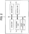
- Fig. 2 is a diagram illustrating a schematic configuration example of the UAV 1.
- the UAV 1 includes a drive unit 11, a positioning unit 12, a radio communication unit 13, an imaging unit 14, a control unit 15, and the like.
- the UAV 1 includes: rotors (propellers) that are horizontal rotary wings; various sensors; an article holding mechanism that holds an article to be transported; a water sprinkling mechanism to drop (sprinkle) water (an example of liquid) that suppresses dust; a battery that supplies power to respective units of the UAV 1; and the like.
- the rotors are the horizontal rotary wings and generate vertical propulsive force.
- the UAV 1 may be equipped with a parachute for emergency landing. Moreover, there may be a case where the UAV 1 includes fixed wings together with the rotors (for example, a case where a UAV is a drone of a VTOL (Vertical TakeOff and Landing) type.
- the various sensors used for flight control of the UAV 1 include a barometric sensor, a three-axis acceleration sensor, a geomagnetic sensor, a weather sensor, and the like.
- the weather sensor is used for monitoring weather conditions. Detection information detected by the various sensors is output to a control unit 15.
- the water sprinkling mechanism includes: a tank that stores the water; a sprinkler that drops the water; and the like. Incidentally, liquid other than the water may also be used to suppress the dust.
- the drive unit 11 includes a motor, a rotating shaft, and the like.
- the drive unit 11 rotates the rotors with the motor, the rotating shaft, and the like that are driven in accordance with a control signal output from the control unit 15.
- the positioning unit 12 includes a radio wave receiver, an altitude sensor, and the like.
- the positioning unit 12 receives, by the radio wave receiver, a radio wave sent from a satellite of a GNSS (Global Navigation Satellite System) and detects a current position (latitude and longitude) in a horizontal direction of the UAV 1 on the basis of the radio wave.
- GNSS Global Navigation Satellite System
- the current position (horizontal position) in the horizontal direction of the UAV 1 may be corrected on the basis of an image captured by the imaging unit 14 or a radio wave sent from the radio base station. Further, the positioning unit 12 may detect the current position (altitude) in a vertical direction of the UAV 1 with the altitude sensor. The position information indicating the current position detected by the positioning unit 12 is output to the control unit 15.
- the radio communication unit 13 controls communication performed via the communication network NW.
- the imaging unit 14 includes a camera (2D or 3D camera) and the like.
- the imaging unit 14 continuously captures images of a real space within a range included in an angle of view of the camera.
- the camera is used not only for flight control of the UAV 1 but also used as a sensor for sensing the destination area of the UAV 1.
- the destination area is, for example, an area located distant from a current position of the UAV 1 in a travel direction by a certain distance or more. In a case where a flight route of the UAV 1 is set, the destination area is located on the flight route, and the UAV 1 is moved in the travel direction along with onward travel.
- the distance is, for example, equal to or longer than a distance at which the UAV 1 is affected by dust. Moreover, the distance may be changed depending on a dust condition in the destination area (for example, the more increased the dust is, the longer the distance is). Moreover, a wording "sensing the destination area" means observing (monitoring) at least any one of the air and the ground in the destination area of the UAV 1 from a viewpoint of the UAV 1, for example. The ground is not constantly flat and may have irregularities.
- sensing data obtained by the sensing is output to the control unit 15.
- the control unit 15 includes a CPU (Central Processing Unit) which is a processor, a ROM (Read Only Memory), a RAM (Random Access Memory), a non-volatile memory, and the like.
- the control unit 15 performs sensing of the destination area by using the sensor such as the camera during the flight of the UAV 1 in accordance with a sensing program stored in the ROM or the non-volatile memory, for example. At this time, preferably, the control unit 15 continuously observes a range that can be detected by the sensor.
- the control unit 15 periodically transmits, to the UTMS 2, the aircraft information of the UAV 1 together with the aircraft ID of the UAV 1 via a radio communication unit 13.
- the control unit 15 transmits the sensing data to the control server CS via the radio communication unit 13 together with the aircraft ID and the aircraft information of the UAV 1.
- control unit 15 executes various kinds of control for the UAV 1 in accordance with a control program stored in, for example, the ROM or the non-volatile memory.
- the various kinds of control include takeoff control, flight control, landing control, water sprinkling control, and article transfer control.
- the position information acquired from a positioning unit 12 the image data acquired from an imaging unit 14, the detection information acquired from the various sensors, position information such as a destination point (a waypoint or a temporary landing point may also be used, and so forth), and the like are used to perform: rotor drive control; and control for a position, a posture, and the travel direction of the UAV 1.
- flight plan information (indicating the flight route of the UAV 1, for example) acquired from the UTMS 2 may also be used.
- the autonomous flight of the UAV 1 is not limited to the autonomous flight performed under the flight control of the control unit 15 provided in the UAV 1, and the autonomous flight of the UAV 1 also includes, for example, autonomous flight performed by flight control as the entire flight system S.
- the landing control is also performed by a control command that is based on the condition of dust in the destination area and provided from, for example, the UTMS 2 or a GCS.
- the control unit 15 (an example of a second selection unit) selects any one landing method from among a plurality of different landing methods in accordance with the control command based on the condition of dust in the destination area.
- Examples of the landing methods can include: (i) a method of making a UAV 1 gradually descend and land by the rotor drive control (normal landing method); (ii) a method of landing by stopping rotor driving and opening a parachute (only in a case where a UAV 1 is equipped with the parachute); and (iii) a method of landing by stopping the rotor driving and performing gliding with fixed wings (for example, gliding while circling around) (only in a case where a UAV 1 includes the fixed wings).
- the water sprinkling control is performed, for example, in the destination area in accordance with a control command that is based on the condition of dust in the destination area and provided from, for example, the UTMS 2 or the GCS.
- the control unit 15 drops (sprinkles) the water that suppresses the dust in the destination area in response to the control command based on the condition of dust in the destination area.
- the article held by the article holding mechanism is transferred from a UAV 1 to a person or an UGV (Unmanned Ground Vehicle), for example, in the destination area and transferred (handed over) to another UAV 1 at a destination point.
- the article transfer control is also performed by a control command that is, for example, provided from the UTMS2 or the GCS and based on the condition of dust in the destination area.
- the control unit 15 (an example of a first selection unit) selects any one article transfer method from among the plurality of different article transfer methods in accordance with the control command based on the condition of dust in the destination area.
- the examples of the article transfer method can include: (iv) a method of making the UAV 1 lower (bring down) an article with, for example, a reel, a winch, or the like in a hovering state for transferring the article; (v) a method of dropping an article (making the article fall) for transferring the article; and (vi) a method of making a UAV 1 land for transferring the article.
- the article transfer method when the article reaches the ground or when the article reaches a height of several meters from the ground, the article is transferred by releasing the article.
- the article transfer method the article is transferred by releasing the article after the UAV 1 has landed on the ground.
- the article may be released by automatically opening a hook that suspends the article (that is, in accordance with a control signal from the control unit 15) or by manually opening the hook that suspends the article (that is, by a person).
- Fig. 3 is a diagram illustrating a schematic configuration example of the control server CS.
- the control server CS includes a communication unit 21, a storage unit 22, a control unit 23, and the like.
- the communication unit 21 controls communication performed via a communication network NW.
- the storage unit 22 includes, for example, a hard disk drive and the like.
- the storage unit 22 stores the aircraft ID of the UAV 1 and the aircraft information of the UAV 1 in a correlated manner.
- the control unit 23 includes: a CPU that is a processor; a ROM; a RAM; a non-volatile memory; and the like.
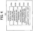
- Fig. 4 is a diagram illustrating exemplary functional blocks in the control unit 23.
- the control unit 23 functions as, for example, a flight route setting unit 23a, a sensing data acquisition unit 23b, an estimation processing unit 23c, a water sprinkling determination unit 23d, an aircraft control unit 23e, and the like in accordance with a program stored in the ROM or the non-volatile memory.
- the flight route setting unit 23a is an example of a setting unit.
- the sensing data acquisition unit 23b is an example of an acquisition unit.
- the estimation processing unit 23c is an example of a processing unit.
- the water sprinkling determination unit 23d is an example of a determination unit.
- the aircraft control unit 23e is an example of a control unit.
- the flight route setting unit 23a sets a flight route of the UAV 1 on the basis of the flight plan application. Moreover, the flight route setting unit 23a resets, on the basis of an estimation result by the estimation processing unit 23c, a flight route of the UAV 1 heading to a destination point along a predetermined flight route (for example, the above-described set flight route). For example, the flight route setting unit 23a resets, on the basis of the condition of dust in the destination area on the flight route of the UAV 1, a flight route that bypasses airspace having heavy dust. Incidentally, a flight route where an altitude is gained higher than that of the current flight route may also be reset.
- the sensing data acquisition unit 23b acquires sensing data obtained by observing the destination area of the UAV 1 with the sensor from a flight position of the UAV 1, and the sensing data is acquired from, for example, the UAV 1 or the GCS together with the aircraft ID of the UAV 1.
- the sensing data includes, for example, image data representing a condition of at least any one of the air and the ground in an area of a scheduled destination.
- the estimation processing unit 23c estimates the condition of dust in the destination area of the UAV 1 on the basis of the sensing data acquired by the sensing data acquisition unit 23b. That is, a dust amount is detected not by actually taking in the dust, but the dust condition is estimated from analysis on the sensing data (for example, image analysis).
- examples of the condition of dust can include a dust degree (level), a dust amount, and the like.
- the dust degree is represented by, for example, stages like "heavy” (level: high), “medium” (level: medium), “light” (level: low) (may also be represented by numerical values, symbols, and the like).
- the dust amount is represented by the mass of the dust contained in 1 m 3 , for example.
- the estimated condition of dust includes at least any one of a current dust condition and a future dust condition.
- the current dust condition refers to a dust condition at a timepoint (that is, a timepoint when the sensing data is obtained) when the UAV 1 is flying toward a destination point.
- the estimation processing unit 23c estimates the dust degree as the current dust condition on the basis of color strength obtained from image data included in the sensing data (for example, the darker the color is, the heavier the dust is).
- the estimation processing unit 23c estimates the dust amount as the current dust condition on the basis of: the color strength obtained from the above-described image data; and a model (for example, a learned model by machine learning) indicating a relation between the color strength and the mass of dust.
- the future dust condition refers to a dust condition at a timepoint after a predetermined period (for example, 5 to 10 minutes later) from a timepoint when the UAV 1 is flying toward the destination point.
- the timepoint after the predetermined period is, for example, scheduled time when the UAV 1 arrives at the destination point.
- the estimation processing unit 23c estimates a dust condition that may be caused in the future by predicting, from the current dust condition, a dust condition after the predetermined period (for example, 5 to 10 minutes).
- the dust condition after the predetermined period is, preferably, predicted from the current dust condition on the basis of, for example, weather forecast (e.g., weather, a wind direction, and the like) after the predetermined period.
- the estimation processing unit 23c may identify a condition of sand (e.g., an amount or a degree of the sand) accumulated on the ground, on the basis of sensing data obtained by observing the ground in the destination area (e.g., the ground in the vicinity of the destination point), and estimate a condition of sand dust that may become airborne in the future from the identified sand condition. For example, a condition in that the more the amount of accumulated sand is, the heavier the sand dust will be in the future is estimated. The reason is that the more the amount of the sand accumulated on the ground is, the more increased an amount of airborne sand dust caused by the wind generated by propulsive force is when the UAV 1 descends.
- a condition of sand e.g., an amount or a degree of the sand
- the water sprinkling determination unit 23d determines, on the basis of the estimation result by the estimation processing unit 23c, whether or not to drop the water that suppresses the dust in the destination area of the UAV 1. For example, in a case where the future dust condition is estimated to be heavy dust by the estimation processing unit 23c, the water sprinkling determination unit 23d determines to drop the water.
- the aircraft control unit 23e controls the UAV 1 in flight on the basis of the estimation result by the estimation processing unit 23c. Such control is performed by, for example, transmitting, to the UAV 1 or the GCS that manages the UAV 1, a control command based on the condition of dust in the destination area. For example, the aircraft control unit 23e performs, on the basis of the estimation result by the estimation processing unit 23c, flight control, water sprinkling control, landing method selection control, or article transfer method selection control for the UAV 1 in flight.
- the aircraft control unit 23e changes the flight route of the UAV 1 currently flying along the predetermined flight route. Consequently, the UAV 1 can be made to fly along the flight route hardly affected by the dust.
- the aircraft control unit 23e may change the flight route of the UAV 1 currently flying along the predetermined flight route in a case where the current dust condition is estimated to be heavy dust by the estimation processing unit 23c.
- the aircraft control unit 23e controls the UAV 1 to drop the water.
- the aircraft control unit 23e selects any one landing method from among the plurality of different landing methods on the basis of the estimation result by the estimation processing unit 23c. Consequently, an appropriate landing method can be selected in accordance with the estimated condition of dust. For example, in a case where the future dust condition is estimated to be heavy dust by the estimation processing unit 23c, the aircraft control unit 23e selects the (ii) or (iii) landing method described above.
- the aircraft control unit 23e selects any one article transfer method from among the plurality of different article transfer methods on the basis of the estimation result by the estimation processing unit 23c. Consequently, it possible to select an appropriate article transfer method in accordance with the estimated condition of dust. For example, in a case where the current dust condition is estimated to be heavy dust by the estimation processing unit 23c, the aircraft control unit 23e selects the (iv) or (v) article transfer method described above.
- the aircraft control unit 23e may also control a hovering UAV 1 on the basis of: a dust condition estimated by the estimation processing unit 23c; and an altitude of the UAV 1 hovering in the destination area.
- control information preset per combination of a dust condition and an altitude of the UAV 1 is used.
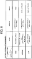
- Figs. 5 and 6 are views illustrating examples of the control information set per combination of a dust condition and an altitude of the UAV 1. Incidentally, in the examples of Figs.
- the dust condition (dust degree) are classified into three stages of "heavy”, “medium”, and “light”, and the altitude of UAV 1 is classified into three stages of "high” (e.g., 100 m or higher), “medium”, and “low” (e.g., lower than 50 m), but may also be classified into two stages, or four or more stages.
- the aircraft control unit 23e makes, in accordance with control information 1 illustrated in Fig. 5 , the UAV 1 wait (wait at the same altitude) in a hovering state or makes the UAV 1 drop an article.
- the aircraft control unit 23e makes the UAV 1 descend in accordance with control information 1 illustrated in Fig. 5 .
- the aircraft control unit 23e makes the UAV 1 further descend or drops the article from the UAV 1.
- the aircraft control unit 23e makes the UAV 1 land.
- the aircraft control unit 23e makes the UAV 1 lower the article with the reel in the hovering state in accordance with control information 2 illustrated in Fig. 6 .
- the aircraft control unit 23e makes the UAV 1 ascend in accordance with the control information 2 illustrated in Fig. 6 .
- the aircraft control unit 23e makes the UAV 1 further ascend.
- the aircraft control unit 23e makes the UAV 1 lower the article with the reel in the hovering state.
- Fig. 7 is a flowchart illustrating exemplary processing performed by the control unit 23 of the control server CS.
- aerial vehicle information of a UAV 1 to be controlled is periodically received in the control server CS.
- the processing illustrated in Fig. 7 is started after the UAV 1 to be controlled starts flying.
- the control unit 23 determines whether or not the UAV 1 currently flying along a predetermined flight route has arrived at the destination point (step S1).
- the determination on arrival at the destination point is performed by determining whether or not a current position of the UAV 1 enters a vicinity range (e.g., several meters) of the destination point on the basis of, for example, position information of the UAV 1 and position information of the destination point.
- step S1 determines that the UAV 1 has not arrived at the destination point (step S1: NO)
- the processing proceeds to step S2.
- step S2 the control unit 23 determines whether or not sensing data obtained by the UAV 1 observing the destination area (that is, sensing from a flight position away from the destination area) is acquired via the communication unit 21. In a case where the control unit 23 determines that the sensing data is acquired (step S2: YES), the processing proceeds to step S3. On the other hand, in a case where the control unit 23 determines that the sensing data is not acquired (step S2: NO), the processing proceeds to step S4.
- step S3 the control unit 23 estimates the condition of dust in the destination area of the UAV 1 on the basis of the sensing data acquired in step S2. For example, both a current dust condition and a future dust condition are estimated by the estimation processing unit 23c. Pieces of information each indicating the estimated dust condition is stored in the storage unit 22 in time series in a manner such that each piece of the information is correlated to: a condition category indicating the current condition or the future condition; and each estimation time.
- step S4 the control unit 23 determines, on the basis of the estimation result in step S3, whether or not to change the flight route of the UAV 1 currently flying along the predetermined flight route. For example, in a case where the current dust condition (that is, the dust condition in the destination area located on the flight route of the UAV 1) estimated in step S3 is a first reference level or higher, the control unit 23 determines to change the flight route of the UAV 1 (step S4: YES), and the processing proceeds to step S5.
- the current dust condition that is, the dust condition in the destination area located on the flight route of the UAV 1
- step S4 YES
- whether or not to change the flight route of the UAV 1 may be determined on the basis of results of estimation performed a plurality of times in time series. For example, in a case where an average value (or a maximum value) of the plurality of times of dust conditions (including a most recent dust condition) estimated until a past timepoint is the first reference level or higher, the flight route of the UAV 1 is determined to be changed, and this past timepoint is obtained by tracing back a past predetermined period (e.g., 5 minutes) from estimation time correlated to the most recent dust condition stored in the storage unit 22.
- a past predetermined period e.g., 5 minutes
- step S4 determines not to change the flight route of the UAV 1 (step S4: NO), and the processing returns to step S1.
- the processing returns to step S1.
- step S5 the control unit 23 resets, on the basis of the estimation result in step S3, a flight route that passes through airspace where the current dust condition is less than the first reference level. For example, a flight route that bypasses airspace having heavy dust or a flight route of flying at an altitude having light dust is reset.
- the control unit 23 transmits, to the UAV 1, a control command to change the current flight route of the UAV 1 to the flight route reset in step S5 (step S6), and the processing returns to step S1.
- the control command may also be transmitted to the UAV 1 via the GCS.
- the UAV 1 changes the current flight route to the reset flight route in accordance with the control command from the control server CS in step S6, and continues the flight toward the destination point along the changed flight route.
- step S2 determines that the UAV 1 has arrived at the destination point.
- step S1 determines that the UAV 1 has arrived at the destination point.
- step S7 the control unit 23 determines, on the basis of the estimation result in step S3, whether or not to drop the water that suppresses the dust at the destination point in the destination area of the UAV 1. For example, in a case where the future dust condition estimated in step S3 (for example, in a case where a most recent future dust condition stored in the storage unit 22) is a second reference level or higher, the control unit 23 determines to drop the water that suppresses the dust (step S7: YES), and the processing proceeds to step S8.
- the future dust condition estimated in step S3 for example, in a case where a most recent future dust condition stored in the storage unit 22
- step S7 determines to drop the water that suppresses the dust
- the second reference level may be different from the first reference level.
- whether or not to drop the water that suppresses the dust may be determined on the basis of the results of estimation performed the plurality of times in time series, in a manner similar to the case of determining whether or not to change the flight route of the UAV 1.
- the processing of step S7 may be performed after processing of step S9.
- step S7 determines not to drop the water that suppresses the dust (step S7: NO), and the processing proceeds to step S9.
- step S8 the control unit 23 transmits, to the UAV 1, a control command to drop the water that suppresses the dust, and the processing proceeds to step S9.
- the control command may also be transmitted to the UAV 1 via the GCS.
- the UAV 1 drops the water that suppresses the dust from the sky above the destination point in accordance with the control command from the control server CS in step S8 by the water sprinkling control. Consequently, sand accumulated on the ground can be prevented from becoming airborne as sand dust due to the propulsive force generated by the UAV 1 (that is, the wind generated by the propulsive force).
- step S9 the control unit 23 designates (selects) one article transfer method from among the plurality of article transfer methods on the basis of the estimation result in step S3. For example, in a case where the future dust condition estimated in step S3 is a third reference level or higher, the control unit 23 designates the article transfer method of making the UAV 1 lower the article with the reel or the like in the hovering state (the (iv) article transfer method described above). On the other hand, in a case where the future dust condition estimated in step S3 is less than the third reference level, the article transfer method of making the UAV 1 land (the (vi) article transfer method described above) is designated.
- the third reference level may be different from the first reference level and the second reference level.
- the selection of the article transfer method may also be determined on the basis of the results of estimation performed the plurality of times in time series, in a manner similar to the case of determining whether or not to change the flight route of the UAV 1.
- control unit 23 transmits, to the UAV 1, a control command to select the article transfer method designated in step S9 (step S10), and ends the processing illustrated in Fig. 7 .
- the control command may also be transmitted to the UAV 1 via the GCS.
- the UAV 1 selects one article transfer method in accordance with the control command from the control server CS in step S10, and performs the article transfer control by the selected article transfer method. For example, the UAV 1 lowers the article with the reel in the hovering state, and releases the article when the article reaches the ground or when the article reaches a height of several meters from the ground. Consequently, the sand accumulated on the ground due to the propulsive force generated by UAV 1 can be prevented from becoming airborne as the sand dust.
- step S9 described above the article transfer method is designated, but a landing method of the UAV 1 may be designated instead thereof.
- the control unit 23 designates (selects) one landing method from among the plurality of landing methods on the basis of the estimation result in step S3. For example, in the case where the future dust condition estimated in step S3 is the third reference level or higher, the control unit 23 designates the landing method of landing by stopping the rotor driving and opening the parachute (the (ii) landing method described above). On the other hand, in the case where the future dust condition estimated in step S3 is less than the third reference level, the landing method of making the UAV 1 gradually descend and land by the rotor drive control (the (i) landing method described above) is designated.
- the control unit 23 transmits, to the UAV 1, a control command to select the landing method designated in step S9. Then, the UAV 1 selects one landing method in accordance with the control command from the control server CS, and performs the landing control by the selected landing method. For example, the UAV 1 lands by stopping the rotor driving and opening the parachute. Consequently, the sand accumulated on the ground can be prevented from becoming airborne as the sand dust due to the propulsive force generated by the UAV 1 (that is, the wind generated by the propulsive force).
- the sensing data obtained by observing the destination area with the sensor from the flight position of the UAV 1 is acquired, and the condition of dust in the destination area is estimated on the basis of the sensing data, and therefore, the condition of dust can be estimated before the UAV 1 is affected by the dust. Then, since the UAV 1 is controlled on the basis of such an estimation result, it is possible to make the UAV 1 be hardly affected by the dust during the flight.
- the above-described embodiment is one embodiment of the present invention, and the present invention is not limited to the above-described embodiment, changes from the above-described embodiment can be made on various configurations and the like within a scope not departing from the gist of the present invention, and such cases shall be also included in the technical scope of the present invention.
- the control server CS estimates a condition of dust in a destination area on the basis of sensing data, but instead, the UAV 1 or the GCS may estimate the condition of dust in the destination area on the basis of the sensing data and may control the UAV 1 on the basis of the estimation result.
- a UAV as an aerial vehicle capable of flying unmanned
- the present invention is also applicable to a manned aerial vehicle capable of flying without an operator (pilot) inside the aerial vehicle.
- a person other than an operator for example, a passenger may board this manned aerial vehicle.
Landscapes
- Engineering & Computer Science (AREA)
- Aviation & Aerospace Engineering (AREA)
- Physics & Mathematics (AREA)
- General Physics & Mathematics (AREA)
- Control Of Position, Course, Altitude, Or Attitude Of Moving Bodies (AREA)
- Traffic Control Systems (AREA)
Abstract
Description
- The present invention relates to a technical field of a system and the like including an aerial vehicle that includes a sensor and is capable of flying unmanned.
- Conventionally, a dust amount in a periphery of an unmanned aerial vehicle can be acquired by a sensor included in the unmanned aerial vehicle. For example,
Patent Literature 1 discloses a technology in which a peripheral dust amount acquired by a sensor installed in an unmanned aerial vehicle is evaluated per coordinates, and in a case where a peripheral environment of the unmanned aerial vehicle is changed into the one not suitable for flying, the unmanned aerial vehicle is moved to an appropriate position. - Patent Literature 1:
JP 2018-191124 A - In related art of
Patent Literature 1 or the like, a sensor can directly detect dust such as sand dust generated in a periphery of the unmanned aerial vehicle. However, in a case where a large amount of dust is generated in the periphery of the unmanned aerial vehicle during flight of the unmanned aerial vehicle, the unmanned aerial vehicle may be affected by the dust. - Therefore, one or more embodiments of the present invention have been made in view of the above circumstances, and are directed to providing a processing system, an aerial vehicle, and a dust condition estimation method which are capable of estimating a condition of dust before the aerial vehicle capable of flying unmanned is affected by the dust.
- In response to the above issue, the invention according to
claim 1 is a processing system including an aerial vehicle that includes a sensor and is capable of flying unmanned. The processing system includes: an acquisition unit configured to acquire sensing data obtained by observing, with the sensor, an area of a scheduled destination of the aerial vehicle from a flight position of the aerial vehicle; and a processing unit configured to estimate, on the basis of the sensing data, a condition of dust in the area of the scheduled destination. Consequently, it is possible to estimate the condition of dust before the aerial vehicle capable of flying unmanned is affected by the dust. - The invention according to
claim 2 is the processing system according toclaim 1 further comprising a control unit configured to control the aerial vehicle on the basis of an estimation result by the processing unit. Consequently, it is possible to make the aerial vehicle capable of flying unmanned be hardly affected by the dust. - The invention according to
claim 3 is the processing system according toclaim 2, wherein the control unit changes, on the basis of the estimation result by the processing unit, a flight route of the aerial vehicle currently flying along a predetermined flight route. Consequently, it is possible to make the aerial vehicle capable of flying unmanned fly along the flight route hardly affected by the dust. - The invention according to claim 4 is the processing system according to any one of
claims 1 to 3 further including a setting unit configured to reset, on the basis of an estimation result by the processing unit, a flight route of the aerial vehicle currently flying along a predetermined flight route. Consequently, it is possible to make the aerial vehicle capable of flying unmanned fly along the flight route hardly affected by the dust. - The invention according to claim 5 is the processing system according to any one of
claims 1 to 4 further including a determination unit configured to determine, on the basis of an estimation result by the processing unit, whether or not to drop liquid that suppresses the dust in the area of the scheduled destination. Consequently, sand accumulated on the ground due to propulsive force generated by the aerial vehicle capable of flying unmanned can be prevented from becoming airborne as sand dust. - The invention according to claim 6 is the processing system according to any one of
claims 1 to 5, wherein the aerial vehicle transports an article to be transferred in the area of the scheduled destination, and the processing system further includes a first selection unit configured t o select, on the basis of an estimation result by the processing unit, any one article transfer method from among a plurality of different article transfer methods. Consequently, it is possible to select an appropriate article transfer method in accordance with the estimated condition of dust. - The invention according to claim 7 is the control device according to claim 6, wherein the first selection unit selects an article transfer method of making the aerial vehicle lower the article while making the aircraft hover for transferring the article. Consequently, sand accumulated on the ground due to propulsive force generated by the aerial vehicle capable of flying unmanned can be prevented from becoming airborne as sand dust.
- The invention according to claim 8 is the control device according to claim 6, wherein the first selection unit selects an article transfer method of making the aerial vehicle land for transferring the article.
- The invention according to claim 9 is the processing system according to any one of
claims 1 to 8, wherein the aerial vehicle lands on the area of the scheduled destination, and the processing system further includes a second selection unit configured to select, on the basis of an estimation result by the processing unit, any one landing method from among a plurality of different landing methods. Consequently, it is possible to select an appropriate landing method in accordance with the estimated condition of dust. - The invention according to claim 10 is the processing system according to any one of
claims 1 to 9, wherein the processing unit estimates, on the basis of sensing data obtained by observing a ground in the area of the scheduled destination, a condition of dust that may be caused in future in the area of the scheduled destination. Consequently, it is possible to detect the condition of the sand accumulated on the ground, and detect the condition of dust that may be caused in the future. - The invention according to
claim 11 is the processing system according to claim 10, wherein the processing unit estimates, on the basis of a condition of at least any one of dust and sand accumulated on the ground, a condition of dust that may become airborne in the future. Consequently, it is possible to estimate, from the condition of at least any one of the dust and the sand accumulated on the ground, the condition of dust that may be caused by the propulsive force generated by the aerial vehicle capable of flying unmanned. - The invention according to
claim 12 is an aerial vehicle capable of flying unmanned. The aerial vehicle includes: a sensor; an acquisition unit configured to acquire sensing data obtained by observing, with the sensor, an area of a scheduled destination of the aerial vehicle from a flight position of the aerial vehicle; and a processing unit configured to estimate, on the basis of the sensing data, a condition of dust in the area of the scheduled destination. - The invention according to
claim 13 is a dust condition estimation method performed by a processing system comprising an aerial vehicle that includes a sensor and is capable of flying unmanned. The dust condition estimation method includes: a step of acquiring sensing data obtained by observing, with the sensor, an area of a scheduled destination of the aerial vehicle from a flight position of the aerial vehicle; and a step of estimating, on the basis of the sensing data, a condition of dust in the area of the scheduled destination. - According to one or more embodiments of the present invention, it is possible to estimate the condition of dust before the aerial vehicle capable of flying unmanned is affected by the dust.
-
-
Fig. 1 is a diagram illustrating a schematic configuration example of a flight system S. -
Fig. 2 is a diagram illustrating a schematic configuration example of anUAV 1. -
Fig. 3 is a diagram illustrating a schematic configuration example of a control server CS. -
Fig. 4 is a diagram illustrating exemplary functional blocks in acontrol unit 23. -
Fig. 5 is a view illustrating examples of a control information set per combination of a dust condition and an altitude of anUAV 1. -
Fig. 6 Fig 6 is a view illustrating examples of a control information set per combination of a dust condition and an altitude of anUAV 1. -
Fig. 7 is a flowchart illustrating exemplary processing performed by acontrol unit 23 of a control server CS. - Hereinafter, an embodiment of the present invention will be described with reference to the drawings. Incidentally, the embodiment described below is an embodiment of a case where a present invention is applied to a flight system.
- First, referring to
Fig. 1 , a description will be provided for a configuration and an outline of operation of a flight system S by which an aerial vehicle capable of flying unmanned is made to fly for a predetermined purpose. Examples of the predetermined purpose can include transportation, surveying, image capturing, inspection, monitoring, and the like.Fig. 1 is a diagram illustrating a schematic configuration example of the flight system S. As illustrated inFig. 1 , the flight system S (an example of a processing system) includes: an unmanned aerial vehicle (hereinafter referred to as an "UAV (Unmanned Aerial Vehicle)") 1 that flies in atmosphere (in air); a traffic management system (hereinafter referred to as a "UTMS (UAV Traffic Management System)") 2; and a port management system (hereinafter referred to as a "PMS (Port Management System)") 3. TheUAV 1, the UTMS 2, and thePMS 3 can communicate with one another via a communication network NW. The communication network NW includes, for example, the Internet, a mobile communication network, a radio base station thereof, and the like. Incidentally, although oneUAV 1 is shown in the example ofFIG. 1 , there may be a plurality ofUAVs 1. The UTMS 2 and the PMS 3 may be configured as one management system. - The
UAV 1 can fly in accordance with remote control from the ground by an operator or can fly autonomously. TheUAV 1 is an example of an aerial vehicle capable of flying unmanned. The UAV 1 is also called a drone or a multi-copter. TheUAV 1 observes, with a sensor, an area of a scheduled destination (hereinafter referred to as a "destination area") from an own flight position during flight (hereinafter, observing is also referred to as sensing (remote sensing)). Sensing data obtained by this sensing is used in the flight system S to estimate a condition of dust in the destination area of theUAV 1. Here, the dust refers to airborne (floating) dust-like particles in the air. In the case where the particles are sand, the dust will be also referred to as sand dust (sandy dust). TheUAV 1 is managed by a GCS (Ground Control Station). For example, the GCS is installed as an application in a control terminal that can be connected to the communication network NW. In this case, the operator is, for example, a person who operates the control terminal to remotely control theUAV 1. Alternatively, the GCS may be configured by a server or the like. In this case, the operator is, for example, a manager in the GCS or a controller provided in the server. - The
UTMS 2 includes one or more servers including a control server CS. TheUTMS 2 manages traffic and flight of theUAV 1. The traffic management of aUAV 1 includes management of a traffic plan of theUAV 1; management of a flight status of theUAV 1, and control of theUAV 1. The traffic plan of theUAV 1 is a flight plan including, for example, a flight route (scheduled route) from a departure point (flight start point) to a destination point (or a waypoint) for theUAV 1. The flight route is represented by, for example, latitude and longitude on the route, and may include flight altitude. The management and control of the flight status of theUAV 1 is performed on the basis of aircraft information of theUAV 1. The aircraft information of theUAV 1 includes at least position information of theUAV 1. The position information of theUAV 1 indicates the current position of theUAV 1. The current position of theUAV 1 is a flight position of theUAV 1 in flight. The aircraft information of theUAV 1 may include speed information of theUAV 1. The speed information of theUAV 1 indicates a flight speed of theUAV 1. The control of theUAV 1 includes a control based on the condition of dust estimated in the destination area of theUAV 1. Incidentally, the control of theUAV 1 may include air traffic control such as giving information and instructions to theUAV 1 in accordance with the flight status of theUAV 1. - The
PMS 3 includes one or a plurality of servers and the like. ThePMS 3 manages a takeoff and landing facility (hereinafter, referred to as "port"), for example, that is installed at the destination point (or the waypoint) in the destination area of theUAV 1. The port is managed on the basis of port position information, port reservation information, and the like. Here, the port position information indicates an installation position of the port. The port reservation information includes: an aircraft ID of theUAV 1 that has reserved the port; information on scheduled arrival time; and the like. The aircraft ID of theUAV 1 is identification information to identify theUAV 1. Incidentally, there may be a case where theUAV 1 lands at a point (hereinafter referred to as "temporary landing point") other than a prepared point like the port. Examples of such cases include: a case where theUAV 1 can hardly keep normal flight due to a sudden change (deterioration) of the weather in the airspace where theUAV 1 flies; a case where theUAV 1 delivers relief articles at the time of disaster; and the like. Generally, the temporary landing point for theUAV 1 is likely to have more sand dust than in prepared ports. - Next, a configuration and an outline of functions of the
UAV 1 will be described with reference toFIG. 2. Fig. 2 is a diagram illustrating a schematic configuration example of theUAV 1. As illustrated inFIG. 2 , theUAV 1 includes adrive unit 11, apositioning unit 12, aradio communication unit 13, animaging unit 14, acontrol unit 15, and the like. Incidentally, although not illustrated, theUAV 1 includes: rotors (propellers) that are horizontal rotary wings; various sensors; an article holding mechanism that holds an article to be transported; a water sprinkling mechanism to drop (sprinkle) water (an example of liquid) that suppresses dust; a battery that supplies power to respective units of theUAV 1; and the like. The rotors are the horizontal rotary wings and generate vertical propulsive force. TheUAV 1 may be equipped with a parachute for emergency landing. Moreover, there may be a case where theUAV 1 includes fixed wings together with the rotors (for example, a case where a UAV is a drone of a VTOL (Vertical TakeOff and Landing) type. The various sensors used for flight control of theUAV 1 include a barometric sensor, a three-axis acceleration sensor, a geomagnetic sensor, a weather sensor, and the like. The weather sensor is used for monitoring weather conditions. Detection information detected by the various sensors is output to acontrol unit 15. The water sprinkling mechanism includes: a tank that stores the water; a sprinkler that drops the water; and the like.
Incidentally, liquid other than the water may also be used to suppress the dust. - The
drive unit 11 includes a motor, a rotating shaft, and the like. Thedrive unit 11 rotates the rotors with the motor, the rotating shaft, and the like that are driven in accordance with a control signal output from thecontrol unit 15. Thepositioning unit 12 includes a radio wave receiver, an altitude sensor, and the like. For example, thepositioning unit 12 receives, by the radio wave receiver, a radio wave sent from a satellite of a GNSS (Global Navigation Satellite System) and detects a current position (latitude and longitude) in a horizontal direction of theUAV 1 on the basis of the radio wave. Incidentally, the current position (horizontal position) in the horizontal direction of theUAV 1 may be corrected on the basis of an image captured by theimaging unit 14 or a radio wave sent from the radio base station. Further, thepositioning unit 12 may detect the current position (altitude) in a vertical direction of theUAV 1 with the altitude sensor. The position information indicating the current position detected by thepositioning unit 12 is output to thecontrol unit 15. - The
radio communication unit 13 controls communication performed via the communication network NW. Theimaging unit 14 includes a camera (2D or 3D camera) and the like. Theimaging unit 14 continuously captures images of a real space within a range included in an angle of view of the camera. The camera is used not only for flight control of theUAV 1 but also used as a sensor for sensing the destination area of theUAV 1. Here, the destination area is, for example, an area located distant from a current position of theUAV 1 in a travel direction by a certain distance or more. In a case where a flight route of theUAV 1 is set, the destination area is located on the flight route, and theUAV 1 is moved in the travel direction along with onward travel. It is desirable that the distance is, for example, equal to or longer than a distance at which theUAV 1 is affected by dust. Moreover, the distance may be changed depending on a dust condition in the destination area (for example, the more increased the dust is, the longer the distance is). Moreover, a wording "sensing the destination area" means observing (monitoring) at least any one of the air and the ground in the destination area of theUAV 1 from a viewpoint of theUAV 1, for example. The ground is not constantly flat and may have irregularities. As a sensor used for such sensing, not only an optical sensor such as a camera (for example, a sensor that detects visible rays or infrared rays reflected from an object) but also a microwave (radio wave) sensor or an ultrasonic sensor can be applied. Incidentally, sensing data obtained by the sensing is output to thecontrol unit 15. - The
control unit 15 includes a CPU (Central Processing Unit) which is a processor, a ROM (Read Only Memory), a RAM (Random Access Memory), a non-volatile memory, and the like. Thecontrol unit 15 performs sensing of the destination area by using the sensor such as the camera during the flight of theUAV 1 in accordance with a sensing program stored in the ROM or the non-volatile memory, for example. At this time, preferably, thecontrol unit 15 continuously observes a range that can be detected by the sensor. Incidentally, during the flight of theUAV 1, thecontrol unit 15 periodically transmits, to theUTMS 2, the aircraft information of theUAV 1 together with the aircraft ID of theUAV 1 via aradio communication unit 13. In a case where the sensing data is obtained by sensing the destination area, thecontrol unit 15 transmits the sensing data to the control server CS via theradio communication unit 13 together with the aircraft ID and the aircraft information of theUAV 1. - Moreover, the
control unit 15 executes various kinds of control for theUAV 1 in accordance with a control program stored in, for example, the ROM or the non-volatile memory. The various kinds of control include takeoff control, flight control, landing control, water sprinkling control, and article transfer control. In the flight control and the landing control, the position information acquired from apositioning unit 12, the image data acquired from animaging unit 14, the detection information acquired from the various sensors, position information such as a destination point (a waypoint or a temporary landing point may also be used, and so forth), and the like are used to perform: rotor drive control; and control for a position, a posture, and the travel direction of theUAV 1. In such flight control, for example, flight plan information (indicating the flight route of theUAV 1, for example) acquired from theUTMS 2 may also be used. Incidentally, the autonomous flight of theUAV 1 is not limited to the autonomous flight performed under the flight control of thecontrol unit 15 provided in theUAV 1, and the autonomous flight of theUAV 1 also includes, for example, autonomous flight performed by flight control as the entire flight system S. - Moreover, the landing control is also performed by a control command that is based on the condition of dust in the destination area and provided from, for example, the
UTMS 2 or a GCS. For example, the control unit 15 (an example of a second selection unit) selects any one landing method from among a plurality of different landing methods in accordance with the control command based on the condition of dust in the destination area. Examples of the landing methods can include: (i) a method of making aUAV 1 gradually descend and land by the rotor drive control (normal landing method); (ii) a method of landing by stopping rotor driving and opening a parachute (only in a case where aUAV 1 is equipped with the parachute); and (iii) a method of landing by stopping the rotor driving and performing gliding with fixed wings (for example, gliding while circling around) (only in a case where aUAV 1 includes the fixed wings). On the other hand, the water sprinkling control is performed, for example, in the destination area in accordance with a control command that is based on the condition of dust in the destination area and provided from, for example, theUTMS 2 or the GCS. For example, thecontrol unit 15 drops (sprinkles) the water that suppresses the dust in the destination area in response to the control command based on the condition of dust in the destination area. - In the article transfer control, for example, the article held by the article holding mechanism is transferred from a
UAV 1 to a person or an UGV (Unmanned Ground Vehicle), for example, in the destination area and transferred (handed over) to anotherUAV 1 at a destination point. The article transfer control is also performed by a control command that is, for example, provided from the UTMS2 or the GCS and based on the condition of dust in the destination area. For example, the control unit 15 (an example of a first selection unit) selects any one article transfer method from among the plurality of different article transfer methods in accordance with the control command based on the condition of dust in the destination area. The examples of the article transfer method can include: (iv) a method of making theUAV 1 lower (bring down) an article with, for example, a reel, a winch, or the like in a hovering state for transferring the article; (v) a method of dropping an article (making the article fall) for transferring the article; and (vi) a method of making aUAV 1 land for transferring the article. According to the (iv) article transfer method, when the article reaches the ground or when the article reaches a height of several meters from the ground, the article is transferred by releasing the article. On the other hand, according to the (vi) article transfer method, the article is transferred by releasing the article after theUAV 1 has landed on the ground. Incidentally, the article may be released by automatically opening a hook that suspends the article (that is, in accordance with a control signal from the control unit 15) or by manually opening the hook that suspends the article (that is, by a person). - Next, a configuration and an outline of functions of the control server CS will be described with reference to
Figs. 3 and4 .Fig. 3 is a diagram illustrating a schematic configuration example of the control server CS. As illustrated inFig. 3 , the control server CS includes acommunication unit 21, astorage unit 22, acontrol unit 23, and the like. Thecommunication unit 21 controls communication performed via a communication network NW. Thestorage unit 22 includes, for example, a hard disk drive and the like. Thestorage unit 22 stores the aircraft ID of theUAV 1 and the aircraft information of theUAV 1 in a correlated manner. - The
control unit 23 includes: a CPU that is a processor; a ROM; a RAM; a non-volatile memory; and the like.Fig. 4 is a diagram illustrating exemplary functional blocks in thecontrol unit 23. As illustrated inFig. 4 , thecontrol unit 23 functions as, for example, a flightroute setting unit 23a, a sensingdata acquisition unit 23b, anestimation processing unit 23c, a watersprinkling determination unit 23d, anaircraft control unit 23e, and the like in accordance with a program stored in the ROM or the non-volatile memory. Incidentally, the flightroute setting unit 23a is an example of a setting unit. The sensingdata acquisition unit 23b is an example of an acquisition unit. Theestimation processing unit 23c is an example of a processing unit. The watersprinkling determination unit 23d is an example of a determination unit. Theaircraft control unit 23e is an example of a control unit. - In a case where a flight plan application is made from the
UAV 1 or the GCS, for example, the flightroute setting unit 23a sets a flight route of theUAV 1 on the basis of the flight plan application. Moreover, the flightroute setting unit 23a resets, on the basis of an estimation result by theestimation processing unit 23c, a flight route of theUAV 1 heading to a destination point along a predetermined flight route (for example, the above-described set flight route). For example, the flightroute setting unit 23a resets, on the basis of the condition of dust in the destination area on the flight route of theUAV 1, a flight route that bypasses airspace having heavy dust. Incidentally, a flight route where an altitude is gained higher than that of the current flight route may also be reset. - During the flight of the
UAV 1, the sensingdata acquisition unit 23b acquires sensing data obtained by observing the destination area of theUAV 1 with the sensor from a flight position of theUAV 1, and the sensing data is acquired from, for example, theUAV 1 or the GCS together with the aircraft ID of theUAV 1. The sensing data includes, for example, image data representing a condition of at least any one of the air and the ground in an area of a scheduled destination. - The
estimation processing unit 23c estimates the condition of dust in the destination area of theUAV 1 on the basis of the sensing data acquired by the sensingdata acquisition unit 23b. That is, a dust amount is detected not by actually taking in the dust, but the dust condition is estimated from analysis on the sensing data (for example, image analysis). Here, examples of the condition of dust can include a dust degree (level), a dust amount, and the like. The dust degree is represented by, for example, stages like "heavy" (level: high), "medium" (level: medium), "light" (level: low) (may also be represented by numerical values, symbols, and the like). The dust amount is represented by the mass of the dust contained in 1 m3, for example. - Moreover, the estimated condition of dust includes at least any one of a current dust condition and a future dust condition. The current dust condition refers to a dust condition at a timepoint (that is, a timepoint when the sensing data is obtained) when the
UAV 1 is flying toward a destination point. For example, theestimation processing unit 23c estimates the dust degree as the current dust condition on the basis of color strength obtained from image data included in the sensing data (for example, the darker the color is, the heavier the dust is). Moreover, theestimation processing unit 23c estimates the dust amount as the current dust condition on the basis of: the color strength obtained from the above-described image data; and a model (for example, a learned model by machine learning) indicating a relation between the color strength and the mass of dust. - On the other hand, the future dust condition refers to a dust condition at a timepoint after a predetermined period (for example, 5 to 10 minutes later) from a timepoint when the
UAV 1 is flying toward the destination point. The timepoint after the predetermined period is, for example, scheduled time when theUAV 1 arrives at the destination point. For example, theestimation processing unit 23c estimates a dust condition that may be caused in the future by predicting, from the current dust condition, a dust condition after the predetermined period (for example, 5 to 10 minutes). The dust condition after the predetermined period is, preferably, predicted from the current dust condition on the basis of, for example, weather forecast (e.g., weather, a wind direction, and the like) after the predetermined period. - Moreover, the
estimation processing unit 23c may identify a condition of sand (e.g., an amount or a degree of the sand) accumulated on the ground, on the basis of sensing data obtained by observing the ground in the destination area (e.g., the ground in the vicinity of the destination point), and estimate a condition of sand dust that may become airborne in the future from the identified sand condition. For example, a condition in that the more the amount of accumulated sand is, the heavier the sand dust will be in the future is estimated. The reason is that the more the amount of the sand accumulated on the ground is, the more increased an amount of airborne sand dust caused by the wind generated by propulsive force is when theUAV 1 descends. - The water
sprinkling determination unit 23d determines, on the basis of the estimation result by theestimation processing unit 23c, whether or not to drop the water that suppresses the dust in the destination area of theUAV 1. For example, in a case where the future dust condition is estimated to be heavy dust by theestimation processing unit 23c, the watersprinkling determination unit 23d determines to drop the water. - The
aircraft control unit 23e controls theUAV 1 in flight on the basis of the estimation result by theestimation processing unit 23c. Such control is performed by, for example, transmitting, to theUAV 1 or the GCS that manages theUAV 1, a control command based on the condition of dust in the destination area. For example, theaircraft control unit 23e performs, on the basis of the estimation result by theestimation processing unit 23c, flight control, water sprinkling control, landing method selection control, or article transfer method selection control for theUAV 1 in flight. - For example, in the flight control, in a case where the flight route is reset by the flight
route setting unit 23a on the basis of the estimation result by theestimation processing unit 23c, theaircraft control unit 23e changes the flight route of theUAV 1 currently flying along the predetermined flight route. Consequently, theUAV 1 can be made to fly along the flight route hardly affected by the dust. Incidentally, even in a case where the flight route is not reset by the flightroute setting unit 23a, theaircraft control unit 23e may change the flight route of theUAV 1 currently flying along the predetermined flight route in a case where the current dust condition is estimated to be heavy dust by theestimation processing unit 23c. - Moreover, in the water sprinkling control, in a case where the water
sprinkling determination unit 23d determines to drop the water, theaircraft control unit 23e controls theUAV 1 to drop the water. Moreover, in the landing method selection control, theaircraft control unit 23e selects any one landing method from among the plurality of different landing methods on the basis of the estimation result by theestimation processing unit 23c. Consequently, an appropriate landing method can be selected in accordance with the estimated condition of dust. For example, in a case where the future dust condition is estimated to be heavy dust by theestimation processing unit 23c, theaircraft control unit 23e selects the (ii) or (iii) landing method described above. - Moreover, in the article transfer method selection control, the
aircraft control unit 23e selects any one article transfer method from among the plurality of different article transfer methods on the basis of the estimation result by theestimation processing unit 23c. Consequently, it possible to select an appropriate article transfer method in accordance with the estimated condition of dust. For example, in a case where the current dust condition is estimated to be heavy dust by theestimation processing unit 23c, theaircraft control unit 23e selects the (iv) or (v) article transfer method described above. - Incidentally, the
aircraft control unit 23e may also control a hoveringUAV 1 on the basis of: a dust condition estimated by theestimation processing unit 23c; and an altitude of theUAV 1 hovering in the destination area. In this case, control information preset per combination of a dust condition and an altitude of theUAV 1 is used.Figs. 5 and6 are views illustrating examples of the control information set per combination of a dust condition and an altitude of theUAV 1. Incidentally, in the examples ofFigs. 5 and6 , the dust condition (dust degree) are classified into three stages of "heavy", "medium", and "light", and the altitude ofUAV 1 is classified into three stages of "high" (e.g., 100 m or higher), "medium", and "low" (e.g., lower than 50 m), but may also be classified into two stages, or four or more stages. - In the example of
Fig. 5 , in a case where the dust is estimated as "MEDIUM" by theestimation processing unit 23c and the altitude of theUAV 1 at the time is determined as "MEDIUM", theaircraft control unit 23e makes, in accordance withcontrol information 1 illustrated inFig. 5 , theUAV 1 wait (wait at the same altitude) in a hovering state or makes theUAV 1 drop an article. Moreover, in a case where the dust is estimated as "LIGHT" by theestimation processing unit 23c and the altitude of theUAV 1 at the time is determined as "HIGH", theaircraft control unit 23e makes theUAV 1 descend in accordance withcontrol information 1 illustrated inFig. 5 . Then, in a case where the dust at the time is estimated to be still "LIGHT" although the altitude of theUAV 1 has become "MEDIUM" by making theUAV 1 descend, theaircraft control unit 23e makes theUAV 1 further descend or drops the article from theUAV 1. On the other hand, in a case where the dust at the time is estimated to be still "LIGHT" although the altitude ofUAV 1 has become "LOW" by making theUAV 1 descend, theaircraft control unit 23e makes theUAV 1 land. - On the other hand, in the example of
Fig. 6 , in a case where the dust is estimated as "MEDIUM" by theestimation processing unit 23c and the altitude of theUAV 1 at the time is determined as "MEDIUM", theaircraft control unit 23e makes theUAV 1 lower the article with the reel in the hovering state in accordance withcontrol information 2 illustrated inFig. 6 . Moreover, in a case where the dust is estimated as "HEAVY" by theestimation processing unit 23c and the altitude of theUAV 1 at the time is determined as "LOW", theaircraft control unit 23e makes theUAV 1 ascend in accordance with thecontrol information 2 illustrated inFig. 6 . Then, in a case where the dust at the time is estimated to be still "HEAVY" although the altitude of theUAV 1 has become "MEDIUM" by making theUAV 1 ascend, theaircraft control unit 23e makes theUAV 1 further ascend. On the other hand, in a case where the altitude of theUAV 1 becomes "MEDIUM" by making theUAV 1 ascend and the dust at the time is decreased and estimated as "MEDIUM", theaircraft control unit 23e makes theUAV 1 lower the article with the reel in the hovering state. - Next, operation of the flight system S will be described with reference to
Fig. 7. Fig. 7 is a flowchart illustrating exemplary processing performed by thecontrol unit 23 of the control server CS. Incidentally, assume that aerial vehicle information of aUAV 1 to be controlled is periodically received in the control server CS. - The processing illustrated in
Fig. 7 is started after theUAV 1 to be controlled starts flying. When the processing illustrated inFig. 7 is started, thecontrol unit 23 determines whether or not theUAV 1 currently flying along a predetermined flight route has arrived at the destination point (step S1). The determination on arrival at the destination point is performed by determining whether or not a current position of theUAV 1 enters a vicinity range (e.g., several meters) of the destination point on the basis of, for example, position information of theUAV 1 and position information of the destination point. In a case where thecontrol unit 23 determines that theUAV 1 has not arrived at the destination point (step S1: NO), the processing proceeds to step S2. - In step S2, the
control unit 23 determines whether or not sensing data obtained by theUAV 1 observing the destination area (that is, sensing from a flight position away from the destination area) is acquired via thecommunication unit 21. In a case where thecontrol unit 23 determines that the sensing data is acquired (step S2: YES), the processing proceeds to step S3. On the other hand, in a case where thecontrol unit 23 determines that the sensing data is not acquired (step S2: NO), the processing proceeds to step S4. - In step S3, as described above, the
control unit 23 estimates the condition of dust in the destination area of theUAV 1 on the basis of the sensing data acquired in step S2. For example, both a current dust condition and a future dust condition are estimated by theestimation processing unit 23c. Pieces of information each indicating the estimated dust condition is stored in thestorage unit 22 in time series in a manner such that each piece of the information is correlated to: a condition category indicating the current condition or the future condition; and each estimation time. - In step S4, the
control unit 23 determines, on the basis of the estimation result in step S3, whether or not to change the flight route of theUAV 1 currently flying along the predetermined flight route. For example, in a case where the current dust condition (that is, the dust condition in the destination area located on the flight route of the UAV 1) estimated in step S3 is a first reference level or higher, thecontrol unit 23 determines to change the flight route of the UAV 1 (step S4: YES), and the processing proceeds to step S5. - Incidentally, whether or not to change the flight route of the
UAV 1 may be determined on the basis of results of estimation performed a plurality of times in time series. For example, in a case where an average value (or a maximum value) of the plurality of times of dust conditions (including a most recent dust condition) estimated until a past timepoint is the first reference level or higher, the flight route of theUAV 1 is determined to be changed, and this past timepoint is obtained by tracing back a past predetermined period (e.g., 5 minutes) from estimation time correlated to the most recent dust condition stored in thestorage unit 22. - On the other hand, in a case where the current dust condition estimated in step S3 is less than the first reference level, the
control unit 23 determines not to change the flight route of the UAV 1 (step S4: NO), and the processing returns to step S1. Incidentally, in a case where the dust condition is not yet estimated at the time of determination in step S4, the processing returns to step S1. - In step S5, the
control unit 23 resets, on the basis of the estimation result in step S3, a flight route that passes through airspace where the current dust condition is less than the first reference level. For example, a flight route that bypasses airspace having heavy dust or a flight route of flying at an altitude having light dust is reset. Next, thecontrol unit 23 transmits, to theUAV 1, a control command to change the current flight route of theUAV 1 to the flight route reset in step S5 (step S6), and the processing returns to step S1. The control command may also be transmitted to theUAV 1 via the GCS. - Then, the
UAV 1 changes the current flight route to the reset flight route in accordance with the control command from the control server CS in step S6, and continues the flight toward the destination point along the changed flight route. - The steps S2 to S6 above are repeated until it is determined that the
UAV 1 has arrived at the destination point. Then, in a case where thecontrol unit 23 determines that theUAV 1 has arrived at the destination point (step S1: YES), the processing proceeds to step S7. - In step S7, the
control unit 23 determines, on the basis of the estimation result in step S3, whether or not to drop the water that suppresses the dust at the destination point in the destination area of theUAV 1. For example, in a case where the future dust condition estimated in step S3 (for example, in a case where a most recent future dust condition stored in the storage unit 22) is a second reference level or higher, thecontrol unit 23 determines to drop the water that suppresses the dust (step S7: YES), and the processing proceeds to step S8. - Incidentally, the second reference level may be different from the first reference level. Moreover, whether or not to drop the water that suppresses the dust may be determined on the basis of the results of estimation performed the plurality of times in time series, in a manner similar to the case of determining whether or not to change the flight route of the
UAV 1. Moreover, the processing of step S7 may be performed after processing of step S9. - On the other hand, in a case where the future dust condition estimated in step S3 is less than the second reference level, the
control unit 23 determines not to drop the water that suppresses the dust (step S7: NO), and the processing proceeds to step S9. - In step S8, the
control unit 23 transmits, to theUAV 1, a control command to drop the water that suppresses the dust, and the processing proceeds to step S9. The control command may also be transmitted to theUAV 1 via the GCS. - Then, the
UAV 1 drops the water that suppresses the dust from the sky above the destination point in accordance with the control command from the control server CS in step S8 by the water sprinkling control. Consequently, sand accumulated on the ground can be prevented from becoming airborne as sand dust due to the propulsive force generated by the UAV 1 (that is, the wind generated by the propulsive force). - In step S9, the
control unit 23 designates (selects) one article transfer method from among the plurality of article transfer methods on the basis of the estimation result in step S3. For example, in a case where the future dust condition estimated in step S3 is a third reference level or higher, thecontrol unit 23 designates the article transfer method of making theUAV 1 lower the article with the reel or the like in the hovering state (the (iv) article transfer method described above). On the other hand, in a case where the future dust condition estimated in step S3 is less than the third reference level, the article transfer method of making theUAV 1 land (the (vi) article transfer method described above) is designated. - Incidentally, the third reference level may be different from the first reference level and the second reference level. Moreover, the selection of the article transfer method may also be determined on the basis of the results of estimation performed the plurality of times in time series, in a manner similar to the case of determining whether or not to change the flight route of the
UAV 1. - Next, the
control unit 23 transmits, to theUAV 1, a control command to select the article transfer method designated in step S9 (step S10), and ends the processing illustrated inFig. 7 . The control command may also be transmitted to theUAV 1 via the GCS. - Then, the
UAV 1 selects one article transfer method in accordance with the control command from the control server CS in step S10, and performs the article transfer control by the selected article transfer method. For example, theUAV 1 lowers the article with the reel in the hovering state, and releases the article when the article reaches the ground or when the article reaches a height of several meters from the ground. Consequently, the sand accumulated on the ground due to the propulsive force generated byUAV 1 can be prevented from becoming airborne as the sand dust. - Incidentally, in step S9 described above, the article transfer method is designated, but a landing method of the
UAV 1 may be designated instead thereof. In this case, thecontrol unit 23 designates (selects) one landing method from among the plurality of landing methods on the basis of the estimation result in step S3. For example, in the case where the future dust condition estimated in step S3 is the third reference level or higher, thecontrol unit 23 designates the landing method of landing by stopping the rotor driving and opening the parachute (the (ii) landing method described above). On the other hand, in the case where the future dust condition estimated in step S3 is less than the third reference level, the landing method of making theUAV 1 gradually descend and land by the rotor drive control (the (i) landing method described above) is designated. - Next, the
control unit 23 transmits, to theUAV 1, a control command to select the landing method designated in step S9. Then, theUAV 1 selects one landing method in accordance with the control command from the control server CS, and performs the landing control by the selected landing method. For example, theUAV 1 lands by stopping the rotor driving and opening the parachute. Consequently, the sand accumulated on the ground can be prevented from becoming airborne as the sand dust due to the propulsive force generated by the UAV 1 (that is, the wind generated by the propulsive force). - As described above, according to the above-described embodiment, the sensing data obtained by observing the destination area with the sensor from the flight position of the
UAV 1 is acquired, and the condition of dust in the destination area is estimated on the basis of the sensing data, and therefore, the condition of dust can be estimated before theUAV 1 is affected by the dust. Then, since theUAV 1 is controlled on the basis of such an estimation result, it is possible to make theUAV 1 be hardly affected by the dust during the flight. Furthermore, according to the above-described embodiment, since a condition of dust that may become airborne in the future can be estimated on the basis of the condition of at least one of the dust and the sand accumulated on the ground in the observed destination area, it is possible to accurately estimate the condition of dust that may be caused by the propulsive force generated by aUAV 1. - Incidentally, the above-described embodiment is one embodiment of the present invention, and the present invention is not limited to the above-described embodiment, changes from the above-described embodiment can be made on various configurations and the like within a scope not departing from the gist of the present invention, and such cases shall be also included in the technical scope of the present invention. For example, in the above-described embodiment, the control server CS estimates a condition of dust in a destination area on the basis of sensing data, but instead, the
UAV 1 or the GCS may estimate the condition of dust in the destination area on the basis of the sensing data and may control theUAV 1 on the basis of the estimation result. - Moreover, in the above-described embodiment, the description is provided by exemplifying a UAV as an aerial vehicle capable of flying unmanned, but the present invention is also applicable to a manned aerial vehicle capable of flying without an operator (pilot) inside the aerial vehicle. A person other than an operator (for example, a passenger) may board this manned aerial vehicle.
-
- 1
- UAV
- 2
- UTMS
- 3
- PMS
- CS
- Control server
- 11
- Drive unit
- 12
- Positioning unit
- 13
- Radio communication unit
- 14
- Imaging unit
- 15
- Control unit
- 21
- Communication unit
- 22
- Storage unit
- 23
- Control unit
- 23a
- Flight route setting unit
- 23b
- Sensing data acquisition unit
- 23c
- Estimation processing unit
- 23d
- Water sprinkling determination unit
- 23e
- Aircraft control unit
- S
- Flight system
Claims (13)
- A processing system including an aerial vehicle that includes a sensor and is capable of flying unmanned, the processing system comprising:an acquisition unit which acquires sensing data obtained by observing, with the sensor, an area of a scheduled destination of the aerial vehicle from a flight position of the aerial vehicle; anda processing unit which estimates, on the basis of the sensing data, a condition of dust in the area of the scheduled destination.
- The processing system according to claim 1, further comprising a control unit which controls the aerial vehicle on the basis of an estimation result by the processing unit.
- The processing system according to claim 2, wherein the control unit changes, on the basis of the estimation result by the processing unit, a flight route of the aerial vehicle currently flying along a predetermined flight route.
- The processing system according to any one of claims 1 to 3, further comprising a setting unit which resets, on the basis of an estimation result by the processing unit, a flight route of the aerial vehicle currently flying along a predetermined flight route.
- The processing system according to any one of claims 1 to 4, further comprising a determination unit which determines, on the basis of an estimation result by the processing unit, whether or not to drop liquid that suppresses the dust in the area of the scheduled destination.
- The processing system according to any one of claims 1 to 5, wherein
the aerial vehicle transports an article to be transferred in the area of the scheduled destination, and
the processing system further comprises a first selection unit which selects, on the basis of an estimation result by the processing unit, any one article transfer method from among a plurality of different article transfer methods. - The control device according to claim 6, wherein the first selection unit selects an article transfer method of making the aerial vehicle lower the article while making the aircraft hover for transferring the article.
- The control device according to claim 6, wherein the first selection unit selects an article transfer method of making the aerial vehicle land for transferring the article.
- The processing system according to any one of claims 1 to 8, wherein
the aerial vehicle lands on the area of the scheduled destination, and
the processing system further comprises a second selection unit which selects, on the basis of an estimation result by the processing unit, any one landing method from among a plurality of different landing methods. - The processing system according to any one of claims 1 to 9, wherein the processing unit estimates, on the basis of sensing data obtained by observing a ground in the area of the scheduled destination, a condition of dust that may be caused in future in the area of the scheduled destination.
- The processing system according to claim 10, wherein the processing unit estimates, on the basis of a condition of at least one of dust and sand accumulated on the ground, a condition of dust that may become airborne in the future.
- An aerial vehicle capable of flying unmanned, comprising:a sensor;an acquisition unit which acquires sensing data obtained by observing, with the sensor, an area of a scheduled destination of the aerial vehicle from a flight position of the aerial vehicle; anda processing unit which estimates, on the basis of the sensing data, a condition of dust in the area of the scheduled destination.
- A dust condition estimation method performed by a processing system comprising an aerial vehicle that includes a sensor and is capable of flying unmanned, the dust condition estimation method including:a step of acquiring sensing data obtained by observing, with the sensor, an area of a scheduled destination of the aerial vehicle from a flight position of the aerial vehicle; anda step of estimating, on the basis of the sensing data, a condition of dust in the area of the scheduled destination.
Applications Claiming Priority (1)
| Application Number | Priority Date | Filing Date | Title |
|---|---|---|---|
| PCT/JP2019/039678 WO2021070253A1 (en) | 2019-10-08 | 2019-10-08 | Processing system, aircraft that can fly unmanned, and dust state estimation method |
Publications (2)
| Publication Number | Publication Date |
|---|---|
| EP3832626A1 true EP3832626A1 (en) | 2021-06-09 |
| EP3832626A4 EP3832626A4 (en) | 2021-09-15 |
Family
ID=74661758
Family Applications (1)
| Application Number | Title | Priority Date | Filing Date |
|---|---|---|---|
| EP19920642.6A Pending EP3832626A4 (en) | 2019-10-08 | 2019-10-08 | TREATMENT SYSTEM, AIRCRAFT CAPABLE OF FLYING WITHOUT PILOTS, AND METHOD OF ESTIMATING THE STATE OF DUST |
Country Status (4)
| Country | Link |
|---|---|
| US (1) | US11928973B2 (en) |
| EP (1) | EP3832626A4 (en) |
| JP (1) | JP6832473B1 (en) |
| WO (1) | WO2021070253A1 (en) |
Families Citing this family (3)
| Publication number | Priority date | Publication date | Assignee | Title |
|---|---|---|---|---|
| US20210394923A1 (en) * | 2017-07-10 | 2021-12-23 | Autel Robotics Co., Ltd. | Aircraft control method and apparatus and aircraft |
| JP7189302B1 (en) * | 2021-10-18 | 2022-12-13 | 楽天グループ株式会社 | Information processing system, notification method, and unmanned aerial vehicle |
| US20250174138A1 (en) * | 2022-03-17 | 2025-05-29 | Nec Corporation | Unmanned aerial vehicle information acquisition system and unmanned aerial vehicle information acquisition method |
Family Cites Families (22)
| Publication number | Priority date | Publication date | Assignee | Title |
|---|---|---|---|---|
| JP2006220445A (en) | 2005-02-08 | 2006-08-24 | Toshiba Corp | Sandstorm prediction system and its sandstorm warning method |
| US8019490B2 (en) * | 2006-09-29 | 2011-09-13 | Applied Minds, Llc | Imaging and display system to aid helicopter landings in brownout conditions |
| US9384668B2 (en) | 2012-05-09 | 2016-07-05 | Singularity University | Transportation using network of unmanned aerial vehicles |
| JP2015026312A (en) | 2013-07-29 | 2015-02-05 | 日立建機株式会社 | Mining vehicle |
| US10696387B2 (en) * | 2013-09-27 | 2020-06-30 | Dann M Allen | Helicopter rotor with a mechanical means for configuring rotor tips to control brown outs |
| JP2015125760A (en) | 2013-12-27 | 2015-07-06 | 日立建機株式会社 | Mine work machine |
| US9483951B1 (en) * | 2014-06-17 | 2016-11-01 | Rockwell Collins, Inc. | Airborne system and method for detecting and avoiding atmospheric particulates |
| CN107771152A (en) * | 2015-04-20 | 2018-03-06 | 乔治·迈克尔·库克 | Aerial delivery components |
| US10071804B1 (en) * | 2015-09-28 | 2018-09-11 | Amazon Technologies, Inc. | Delivery drop rate modulation |
| JP6275202B2 (en) * | 2016-06-23 | 2018-02-07 | エスゼット ディージェイアイ テクノロジー カンパニー リミテッドSz Dji Technology Co.,Ltd | Unmanned aerial vehicle, unmanned aircraft control method, and unmanned aircraft control program |
| JP2018030407A (en) | 2016-08-23 | 2018-03-01 | 株式会社日立製作所 | Transport system and transport method |
| US10395544B1 (en) | 2016-08-29 | 2019-08-27 | Amazon Technologies, Inc. | Electronic landing marker |
| CN106976562A (en) * | 2017-03-24 | 2017-07-25 | 西安旋飞电子科技有限公司 | A kind of dust-proof security protection unmanned plane |
| JP6866203B2 (en) * | 2017-03-28 | 2021-04-28 | 株式会社ゼンリンデータコム | Drone navigation device, drone navigation method, drone navigation program, search data formation device and search data formation program |
| JP2018191124A (en) | 2017-05-02 | 2018-11-29 | 株式会社リコー | Relay device, information processing apparatus, system, relay position determination method, information processing method, and program |
| JP6960627B2 (en) | 2017-07-11 | 2021-11-05 | 株式会社Mmラボ | Unmanned aerial vehicle |
| JP7109174B2 (en) | 2017-10-03 | 2022-07-29 | 株式会社トプコン | Route selection device, unmanned aircraft, data processing device, route selection processing method, and route selection processing program |
| US11155349B2 (en) | 2017-11-06 | 2021-10-26 | Ford Global Technologies, Llc | Method and apparatus for economical refueling of drones |
| JP7034721B2 (en) * | 2018-01-10 | 2022-03-14 | アルパイン株式会社 | Control device and control method for unmanned transport aircraft |
| US10850841B2 (en) | 2018-06-20 | 2020-12-01 | Intel Corporation | Unmanned aerial vehicle and method for operating an unmanned aerial vehicle |
| US11348060B2 (en) * | 2018-08-24 | 2022-05-31 | International Business Machines Corporation | Increasing cost benefit and energy efficiency with modular delivery drones in inclement weather |
| US11392130B1 (en) * | 2018-12-12 | 2022-07-19 | Amazon Technologies, Inc. | Selecting delivery modes and delivery areas using autonomous ground vehicles |
-
2019
- 2019-10-08 WO PCT/JP2019/039678 patent/WO2021070253A1/en not_active Ceased
- 2019-10-08 EP EP19920642.6A patent/EP3832626A4/en active Pending
- 2019-10-08 JP JP2020524918A patent/JP6832473B1/en active Active
- 2019-10-08 US US17/041,128 patent/US11928973B2/en active Active
Also Published As
| Publication number | Publication date |
|---|---|
| US20230108853A1 (en) | 2023-04-06 |
| WO2021070253A1 (en) | 2021-04-15 |
| US11928973B2 (en) | 2024-03-12 |
| JPWO2021070253A1 (en) | 2021-10-21 |
| JP6832473B1 (en) | 2021-02-24 |
| EP3832626A4 (en) | 2021-09-15 |
Similar Documents
| Publication | Publication Date | Title |
|---|---|---|
| JP7300437B2 (en) | Processing system, unmanned flightable aircraft, and method for estimating dust conditions | |
| US12037117B2 (en) | Unmanned aerial vehicle and payload delivery system | |
| EP3693945B1 (en) | Control method for unmanned aerial vehicle, management method, control device, management device, and unmanned aerial vehicle system | |
| US12282339B2 (en) | Processing system, unmanned aerial vehicle, and flight route designation method | |
| JP7327668B2 (en) | POWER SUPPLY INFORMATION DETERMINATION DEVICE, POWER SUPPLY INFORMATION DETERMINATION METHOD, AND PROGRAM | |
| US11928973B2 (en) | Processing system, aerial vehicle capable of flying unmanned, and dust condition estimation method | |
| JP6954983B2 (en) | Information processing equipment, information processing methods, and programs | |
| WO2023010451A1 (en) | Unmanned aerial vehicle scheduling method, server, parking apron pad device, system, and storage medium | |
| AU2022476896B2 (en) | Processes for generating and updating flyable airspace for unmanned aerial vehicles | |
| US11747807B2 (en) | Control device and control method for controlling aerial vehicle | |
| CN113778134A (en) | A ground station for coal mine environment | |
| US11971730B2 (en) | Automated assignment of UAVs to staging pads | |
| US20210097867A1 (en) | Control device, method, and non-transitory computer readable medium for controlling an unmanned aerial vehicle | |
| JP6916255B2 (en) | Management devices, management methods, and programs in flight systems | |
| JP7319420B2 (en) | Processing system, unmanned flightable aircraft, and method for estimating dust conditions | |
| US20250111791A1 (en) | Statistical Estimation of Local Minimum Flyable AGLs based on Probabilities of Planned Flights Intersecting Terrain Estimates | |
| WO2025028077A1 (en) | Monitoring system, monitoring method, and monitoring program |
Legal Events
| Date | Code | Title | Description |
|---|---|---|---|
| STAA | Information on the status of an ep patent application or granted ep patent |
Free format text: STATUS: UNKNOWN |
|
| STAA | Information on the status of an ep patent application or granted ep patent |
Free format text: STATUS: THE INTERNATIONAL PUBLICATION HAS BEEN MADE |
|
| PUAI | Public reference made under article 153(3) epc to a published international application that has entered the european phase |
Free format text: ORIGINAL CODE: 0009012 |
|
| STAA | Information on the status of an ep patent application or granted ep patent |
Free format text: STATUS: REQUEST FOR EXAMINATION WAS MADE |
|
| 17P | Request for examination filed |
Effective date: 20200930 |
|
| AK | Designated contracting states |
Kind code of ref document: A1 Designated state(s): AL AT BE BG CH CY CZ DE DK EE ES FI FR GB GR HR HU IE IS IT LI LT LU LV MC MK MT NL NO PL PT RO RS SE SI SK SM TR |
|
| RAP3 | Party data changed (applicant data changed or rights of an application transferred) |
Owner name: RAKUTEN GROUP, INC. |
|
| A4 | Supplementary search report drawn up and despatched |
Effective date: 20210812 |
|
| RIC1 | Information provided on ipc code assigned before grant |
Ipc: G06Q 10/08 20120101ALI20210806BHEP Ipc: G08G 5/02 20060101ALI20210806BHEP Ipc: G05D 1/10 20060101ALI20210806BHEP Ipc: B64D 9/00 20060101ALI20210806BHEP Ipc: B64D 1/16 20060101ALI20210806BHEP Ipc: B64C 39/02 20060101ALI20210806BHEP Ipc: B64C 13/18 20060101ALI20210806BHEP Ipc: G08G 5/00 20060101AFI20210806BHEP |
|
| DAV | Request for validation of the european patent (deleted) | ||
| DAX | Request for extension of the european patent (deleted) | ||
| STAA | Information on the status of an ep patent application or granted ep patent |
Free format text: STATUS: EXAMINATION IS IN PROGRESS |
|
| 17Q | First examination report despatched |
Effective date: 20240710 |
|
| RIC1 | Information provided on ipc code assigned before grant |
Ipc: G08G 5/00 20060101AFI20260115BHEP Ipc: G08G 5/21 20250101ALI20260115BHEP Ipc: G08G 5/26 20250101ALI20260115BHEP Ipc: G08G 5/34 20250101ALI20260115BHEP Ipc: G08G 5/54 20250101ALI20260115BHEP Ipc: G08G 5/55 20250101ALI20260115BHEP Ipc: G08G 5/57 20250101ALI20260115BHEP Ipc: G08G 5/74 20250101ALI20260115BHEP Ipc: G08G 5/76 20250101ALI20260115BHEP Ipc: G05D 1/00 20060101ALI20260115BHEP Ipc: B64D 1/02 20060101ALI20260115BHEP Ipc: B64D 1/16 20060101ALI20260115BHEP Ipc: B64U 70/83 20230101ALI20260115BHEP |
|
| GRAP | Despatch of communication of intention to grant a patent |
Free format text: ORIGINAL CODE: EPIDOSNIGR1 |
|
| STAA | Information on the status of an ep patent application or granted ep patent |
Free format text: STATUS: GRANT OF PATENT IS INTENDED |
|
| INTG | Intention to grant announced |
Effective date: 20260310 |