EP3832582A1 - Operation information management system, and operation information management method - Google Patents
Operation information management system, and operation information management method Download PDFInfo
- Publication number
- EP3832582A1 EP3832582A1 EP18928250.2A EP18928250A EP3832582A1 EP 3832582 A1 EP3832582 A1 EP 3832582A1 EP 18928250 A EP18928250 A EP 18928250A EP 3832582 A1 EP3832582 A1 EP 3832582A1
- Authority
- EP
- European Patent Office
- Prior art keywords
- sensor
- work
- data
- worker
- wearable
- Prior art date
- Legal status (The legal status is an assumption and is not a legal conclusion. Google has not performed a legal analysis and makes no representation as to the accuracy of the status listed.)
- Granted
Links
Images




Classifications
-
- G—PHYSICS
- G05—CONTROLLING; REGULATING
- G05B—CONTROL OR REGULATING SYSTEMS IN GENERAL; FUNCTIONAL ELEMENTS OF SUCH SYSTEMS; MONITORING OR TESTING ARRANGEMENTS FOR SUCH SYSTEMS OR ELEMENTS
- G05B19/00—Program-control systems
- G05B19/02—Program-control systems electric
- G05B19/418—Total factory control, i.e. centrally controlling a plurality of machines, e.g. direct or distributed numerical control [DNC], flexible manufacturing systems [FMS], integrated manufacturing systems [IMS] or computer integrated manufacturing [CIM]
- G05B19/4183—Total factory control, i.e. centrally controlling a plurality of machines, e.g. direct or distributed numerical control [DNC], flexible manufacturing systems [FMS], integrated manufacturing systems [IMS] or computer integrated manufacturing [CIM] characterised by data acquisition, e.g. workpiece identification
-
- G—PHYSICS
- G06—COMPUTING OR CALCULATING; COUNTING
- G06F—ELECTRIC DIGITAL DATA PROCESSING
- G06F1/00—Details not covered by groups G06F3/00 - G06F13/00 and G06F21/00
- G06F1/16—Constructional details or arrangements
- G06F1/1613—Constructional details or arrangements for portable computers
- G06F1/163—Wearable computers, e.g. on a belt
-
- G—PHYSICS
- G06—COMPUTING OR CALCULATING; COUNTING
- G06F—ELECTRIC DIGITAL DATA PROCESSING
- G06F3/00—Input arrangements for transferring data to be processed into a form capable of being handled by the computer; Output arrangements for transferring data from processing unit to output unit, e.g. interface arrangements
- G06F3/01—Input arrangements or combined input and output arrangements for interaction between user and computer
- G06F3/011—Arrangements for interaction with the human body, e.g. for user immersion in virtual reality
- G06F3/014—Hand-worn input/output arrangements, e.g. data gloves
-
- G—PHYSICS
- G05—CONTROLLING; REGULATING
- G05B—CONTROL OR REGULATING SYSTEMS IN GENERAL; FUNCTIONAL ELEMENTS OF SUCH SYSTEMS; MONITORING OR TESTING ARRANGEMENTS FOR SUCH SYSTEMS OR ELEMENTS
- G05B2219/00—Program-control systems
- G05B2219/30—Nc systems
- G05B2219/31—From computer integrated manufacturing till monitoring
- G05B2219/31027—Computer assisted manual assembly CAA, display operation, tool, result
-
- G—PHYSICS
- G05—CONTROLLING; REGULATING
- G05B—CONTROL OR REGULATING SYSTEMS IN GENERAL; FUNCTIONAL ELEMENTS OF SUCH SYSTEMS; MONITORING OR TESTING ARRANGEMENTS FOR SUCH SYSTEMS OR ELEMENTS
- G05B2219/00—Program-control systems
- G05B2219/30—Nc systems
- G05B2219/35—Nc in input of data, input till input file format
- G05B2219/35464—Glove, movement of fingers
-
- G—PHYSICS
- G06—COMPUTING OR CALCULATING; COUNTING
- G06F—ELECTRIC DIGITAL DATA PROCESSING
- G06F3/00—Input arrangements for transferring data to be processed into a form capable of being handled by the computer; Output arrangements for transferring data from processing unit to output unit, e.g. interface arrangements
- G06F3/14—Digital output to display device ; Cooperation and interconnection of the display device with other functional units
- G06F3/147—Digital output to display device ; Cooperation and interconnection of the display device with other functional units using display panels
-
- G—PHYSICS
- G06—COMPUTING OR CALCULATING; COUNTING
- G06Q—INFORMATION AND COMMUNICATION TECHNOLOGY [ICT] SPECIALLY ADAPTED FOR ADMINISTRATIVE, COMMERCIAL, FINANCIAL, MANAGERIAL OR SUPERVISORY PURPOSES; SYSTEMS OR METHODS SPECIALLY ADAPTED FOR ADMINISTRATIVE, COMMERCIAL, FINANCIAL, MANAGERIAL OR SUPERVISORY PURPOSES, NOT OTHERWISE PROVIDED FOR
- G06Q10/00—Administration; Management
- G06Q10/08—Logistics, e.g. warehousing, loading or distribution; Inventory or stock management
- G06Q10/087—Inventory or stock management, e.g. order filling, procurement or balancing against orders
-
- G—PHYSICS
- G06—COMPUTING OR CALCULATING; COUNTING
- G06Q—INFORMATION AND COMMUNICATION TECHNOLOGY [ICT] SPECIALLY ADAPTED FOR ADMINISTRATIVE, COMMERCIAL, FINANCIAL, MANAGERIAL OR SUPERVISORY PURPOSES; SYSTEMS OR METHODS SPECIALLY ADAPTED FOR ADMINISTRATIVE, COMMERCIAL, FINANCIAL, MANAGERIAL OR SUPERVISORY PURPOSES, NOT OTHERWISE PROVIDED FOR
- G06Q50/00—Information and communication technology [ICT] specially adapted for implementation of business processes of specific business sectors, e.g. utilities or tourism
- G06Q50/04—Manufacturing
-
- G—PHYSICS
- G06—COMPUTING OR CALCULATING; COUNTING
- G06V—IMAGE OR VIDEO RECOGNITION OR UNDERSTANDING
- G06V20/00—Scenes; Scene-specific elements
- G06V20/50—Context or environment of the image
- G06V20/52—Surveillance or monitoring of activities, e.g. for recognising suspicious objects
-
- G—PHYSICS
- G16—INFORMATION AND COMMUNICATION TECHNOLOGY [ICT] SPECIALLY ADAPTED FOR SPECIFIC APPLICATION FIELDS
- G16Y—INFORMATION AND COMMUNICATION TECHNOLOGY SPECIALLY ADAPTED FOR THE INTERNET OF THINGS [IoT]
- G16Y10/00—Economic sectors
- G16Y10/25—Manufacturing
-
- G—PHYSICS
- G16—INFORMATION AND COMMUNICATION TECHNOLOGY [ICT] SPECIALLY ADAPTED FOR SPECIFIC APPLICATION FIELDS
- G16Y—INFORMATION AND COMMUNICATION TECHNOLOGY SPECIALLY ADAPTED FOR THE INTERNET OF THINGS [IoT]
- G16Y40/00—IoT characterised by the purpose of the information processing
- G16Y40/50—Safety; Security of things, users, data or systems
-
- Y—GENERAL TAGGING OF NEW TECHNOLOGICAL DEVELOPMENTS; GENERAL TAGGING OF CROSS-SECTIONAL TECHNOLOGIES SPANNING OVER SEVERAL SECTIONS OF THE IPC; TECHNICAL SUBJECTS COVERED BY FORMER USPC CROSS-REFERENCE ART COLLECTIONS [XRACs] AND DIGESTS
- Y02—TECHNOLOGIES OR APPLICATIONS FOR MITIGATION OR ADAPTATION AGAINST CLIMATE CHANGE
- Y02P—CLIMATE CHANGE MITIGATION TECHNOLOGIES IN THE PRODUCTION OR PROCESSING OF GOODS
- Y02P90/00—Enabling technologies with a potential contribution to greenhouse gas [GHG] emissions mitigation
- Y02P90/02—Total factory control, e.g. smart factories, flexible manufacturing systems [FMS] or integrated manufacturing systems [IMS]
Definitions
- the present invention relates to a technique for managing work information of a worker.
- a matter for visualizing who performed what kind of work and when the work was performed can be used for the purpose of facilitating training of workers and improving work efficiency at the entire site.
- a matter for associating a tool with a worker is effective in managing articles and recognizing a worker or a work state. When whether work has been performed correctly can be immediately fed back to a worker, quality can be improved and worker safety can be improved.
- a wrist band is worn on an arm of a worker who works in an inventory, and a sensor provided on a shelf where articles are stored is used to detect a movement of a hand of the worker.
- touching information between a body and the outside may be used in a workable factory in addition to the situation described above.
- a work state or a worker can be managed if it is possible to know how much strength should be used to hold what kind of tool or confirm that the article is held when the article has a characteristic shape.
- the information can be collected by, for example, wearing on the body a pressure sensor or a wearable object such as a piece of clothing to which the pressure sensor is attached.
- an article such as a tool generally has a unique shape or surface state, and it is difficult to determine what a touched object is like only from a sensor worn on the body.
- An object of the invention is to provide a technique capable of performing work information management by associating a worker with a work content by the worker touching a sensing object via a wearable sensor.
- the work information management system preferably includes a wearable sensor including a sensor that is worn by a worker and receives sensor data from a sensing object and a transmitter that transmits the sensor data received by the sensor to a terminal, and a computer that determines a work content of the worker based on the sensor data received from the wearable sensor and outputs a determination result to a display unit.
- the invention is also known as a work information management method performed by the work information management system described above.
- work information can be managed by associating a worker with a work content by the worker touching a sensing object via a wearable sensor.
- a wearable sensor included in the invention is not limited thereto.
- the wearable sensor may be worn on a part of a foot such as a sole of a foot and a knee, or a part of an arm such as a shoulder or an elbow.
- an example of a mechanism for a worker to acquire data by touching with a part of a body includes a pressure sensor that is mounted to a wearable sensor.
- the pressure sensor may have a plastic shape, or a cloth shape.
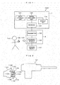
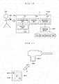
- a work information management system 1000 includes a terminal device 1 and a sensor device 2.
- the terminal device 1 includes a general computer as hardware, receives sensor data from the sensor device 2, and analyzes the sensor data.
- the terminal device 1 includes a receiver 104, a signal analyzing unit 105, a display unit 106, and a data storage unit 107.
- the sensor device 2 includes, as hardware, an object (for example, a glove or a shoe provided with a pressure sensor) such as an appliance, a machine, a tool, or a device that is provided with a wearable sensor 102 and a transmitter 103.
- the sensor device 2 acquires sensor data from the wearable sensor 102, and the transmitter 103 transmits the sensor data to the terminal device 1.
- the sensor device 2 includes the wearable sensor 102 and the transmitter 103.
- the receiver 104 in the terminal device 1 includes a general communication device (for example, a network interface card (NIC)) as hardware, and receives the sensor data from the sensor device 2.
- the signal analyzing unit 105 includes a general arithmetic device (for example, a central processing unit (CPU)) as hardware.
- the signal analyzing unit 105 analyzes the sensor data, displays the sensor data and an analysis result of the sensor data on the display unit 106, and stores the sensor data and the analysis result of the sensor data in the data storage unit 107.
- the data storage unit 107 includes a general storage device (for example, a hard disk drive (HDD) or a solid state drive (SSD)) as hardware, and stores the analysis result of the sensor data from the signal analyzing unit 105.
- the display unit 106 includes a general display (for example, a liquid crystal display (LCD)) as hardware, and displays the analysis result of the sensor data from the signal analyzing unit 105.
- LCD liquid crystal display
- the wearable sensor 102 has a glove shape or the like, and is a device that is internally provided with a sensing device. Alternatively, the wearable sensor 102 may have a cap shape worn on a fingertip, or a shape covering parts of a palm or a back of a hand.
- a worker 100 grips a sensing object 101 or touches a surface of the sensing object 101 with a tip of a hand, or presses the sensing object 101 with a part of the hand, so that the wearable sensor 102 provided in the sensor device 2 obtains sensor data.
- the sensing object 101 may be a tool, an electric machine, or the like used by the worker 100 during working. Alternatively, the sensing object 101 may be a conveying object such as a trolley or food such as fruits.
- the wearable sensor 102 may include a sensor such as a sound sensor, a vibration sensor, and a magnetic sensor at the same time.
- the transmitter 103 may be integrally formed in the wearable sensor 102.
- the transmitter 103 maybe provided in the wearable sensor 102 through a wire for transferring power or an electrical signal.
- the receiver 104 receives an electrical signal including sensor data that is wirelessly transmitted from the transmitter 103.
- the signal analyzing unit 105 reads, from the received electrical signal, the sensor data of the sensing object 101 taken by the worker 100 in hand or touched by the worker 100 with hand, and determines a work content of the worker such as how the worker 100 touches the sensing object 101.
- FIG. 2 shows a configuration example of the sensor device and the sensing object when the signal analyzing unit 105 analyzes the sensor data.
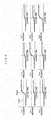
- FIG. 3 shows an example of the sensor data analyzed by the signal analyzing unit 105.
- the wearable sensor 102 in the sensor device 2 is a glove-shaped wearable sensor 1101 that can be worn on a hand of the worker 100, and includes one or plural sensors provided at one or plural parts where the worker 100 touches the sensing object 101.
- the glove-shaped wearable sensor 1101 includes an index finger base pressure sensor 1102 (ch 1), an index finger central pressure sensor 1103 (ch 2), an index finger tip pressure sensor 1104 (ch 3), a middle finger base pressure sensor 1105 (ch 4), a middle finger central pressure sensor 1106 (ch 5), a middle finger tip pressure sensor 1107 (ch 6), a ring finger base pressure sensor 1108 (ch 7), a ring finger central pressure sensor 1109 (ch 8), and a ring finger tip pressure sensor 1110 (ch 9).
- the sensing object 101 is an electric tool or the like held by the worker 100 when cutting a work material.
- the sensor device 2 reads a pressure signal detected by a pressure sensor in each part of the wearable sensor 1101, and transmits information serving as sensor data to the terminal device 1 via the transmitter 103.
- the sensor data includes a pressure value, identification information for identifying the wearable sensor 1101 and a pressure sensor, and a time point when the pressure value is detected.
- FIG. 3 shows an example of the sensor data.
- information in the sensor data indicates a temporal transition of pressure values included in detection signals detected by the wearable sensor.
- the information is transmitted to each wearable sensor.
- FIG. 3 shows that the index finger base pressure sensor 1102 (ch 1), the middle finger central pressure sensor 1106 (ch 5), the ring finger tip pressure sensor 1110 (ch 9), and the like detected pressure exceeding a predetermined threshold 1201 used in pressure evaluation at a time point 1200 indicating a moment when the worker 100 holds a tool.
- pressure values of the other pressure sensors increase at the time point 1200 indicating a moment when the worker 100 holds a tool, the pressure values do not exceed the threshold 1201.
- the signal analyzing unit 105 determines that the sensing object 101 is gripped by an index finger base, a middle finger center, and a ring finger tip as a work content of the worker 100, and outputs the determination result as an analysis result. For example, the signal analyzing unit 105 outputs to the display unit 106 a message indicating that the sensing object 101 is gripped by the index finger base, the middle finger center, and the ring finger tip, pressure values when the sensing object 101 is gripped, and a time point.
- the signal analyzing unit 105 may compare the above-described sensor data used when determining the work content with reference sensor data that defines a criterion to be satisfied in the work, determine whether the sensor data satisfies the reference sensor data, and output a determination result and an analysis result to the display unit 106.
- the reference sensor data may be pre-stored in the data storage unit 107 on a work basis. With such a configuration, an administrator can easily determine what kind of work state the worker is in, what kind of work content is performed, and whether the work content satisfies a criterion.
- the sensor data obtained by touching may not be a pressure value and may be, for example, a level indicating a strength at which the sensing object 101 is touched by the wearable sensor 120.
- the sensor data may be a change rate of a touching strength indicating how the touching strength changes within a certain period of time.
- the display unit 106 may be provided in the sensor device 2 and may be implemented to be directly visible to the worker 100.
- the display unit 106 may include a monitor that is checked by another person such as an administrator at a position away from the worker 100 or checked by both the administrator and the worker 100.
- the signal analyzing unit 105 may transmit an analysis result to the monitor via wireless communication to display the analysis result.
- a content displayed as the analysis result may relate to sensor data in real time when the worker 100 works.
- the content displayed as the analysis result may be a result obtained by comparing the sensor data in real time when the worker 100 works with sensor data of previous work, or a result obtained by analyzing the previous work. In this case, a change in a degree of proficiency of the worker or the like can be known by comparing sensor data during current work of the worker 100 with sensor data during previous work of the worker 100.
- the display unit 106 may only display visual information, or may display a combination of tactile information such as sound and vibration and visual information. In addition, the display unit 106 may only display tactile information instead of visual information, or may display information obtained by the worker or a person other than the worker. The same may be applied to the second and subsequent embodiments.
- the data storage unit 107 stores sensor data of the sensing object 101 touched by each worker 100 for each part of the wearable sensor 102.
- the data storage unit 107 stores work data of a working object serving as the sensing object 101 corresponding to the sensor data.
- the work data includes time spent on the work, a date and time when the work is performed, a worker ID for identifying the worker 100, and the like.
- the IC chip provided in the wearable sensor 102 of the sensor device 2 transmits the time spent on the work, the date and time when the work is performed, and the worker ID to the terminal device 1 as the work data.
- the IC chip counts a period of time from a time point when the wearable sensor 102 detects pressure up to a time point when the wearable sensor 102 detects no pressure.
- the period of time may serve as the time spent on the work.
- the IC chip reads a current time point counted by a timer (not shown) .
- the current time point may serve as the date and time when the work is performed.
- the worker ID may be a worker ID obtained by the IC chip reading a worker ID pre-stored in a memory (not shown) of the worker 100 who uses the sensor device 2.
- Data stored in the data storage unit 107 may be the sensor data received by the receiver 104 of the terminal device 1, or an analysis result of the signal analyzing unit 105, or both the analysis result and the sensor data.
- the data storage unit 107 may temporarily store real-time sensor data received from the sensor device 2 by the receiver 104 at any time, or may continue storing previous sensor data.
- the data storage unit 107 may store data in an electronic medium, or may print data on a printing medium.
- the work information management system includes the sensor device 2 and the terminal device 1.
- the sensor device 2 includes a sensor that is worn by a worker and receives sensor data from the sensing object 101, and the wearable sensor 102 that includes the transmitter 103 that transmits the sensor data received from the sensor to the terminal device 1.
- the terminal device 1 determines a work content of the worker based on the sensor data received from the wearable sensor 102 and outputs the determination result to the display unit 106. Accordingly, the work content of the worker can be easily known using the sensor device 2.
- work information of the worker can be associated with a working object by using the sensor data and the work data, and a work history and a work content, for example, when and where the worker performs what kind of work, can be managed. That is, work on a working obj ect can be detected or estimated by a worker touching the working object, and work information can be managed by associating the worker with a work content according to the detection or estimation.
- a supervisor of the worker 100 may use the sensor device 2 to touch the sensing object 101, and sensor data indicating a correct touching manner of the sensing object 101 may be stored in the data storage unit 107 in advance as a model. Then, the signal analyzing unit 105 compares sensor data obtained when the worker 100 works with the model to determine a deviation degree between the sensor data and the model, and displays an analysis result on the display unit 106, so that a correct using manner of the sensing object 101 can be taught to the worker 100.
- the signal analyzing unit 105 displays, on the display unit 106, an advice message such as "a holding manner of the index finger is weak, please hold a litter stronger".
- a work information management system 2000 according to the second embodiment has a more specific device configuration than the work information management system 100 according to the first embodiment.
- the work management system 2000 includes the sensor device 2 the same as the sensor device in the first embodiment, an IoT gateway 201, and a server 3.
- a sensing object 200 is implemented by an object (for example, a tool that can store information and count time) that can obtain work data such as sensing object identification information (ID), ID indicating an installation place of the sensing object, a user of the sensing object, and time when the sensing object is operated.
- Work data according to the present embodiment may include the work data according to the first embodiment.
- the IoT gateway 201 includes a general communication computer (for example, a gateway server) as hardware, and performs data shaping to transmit a wireless signal including sensor data transmitted from the transmitter 103 to a network 202.
- a general communication computer for example, a gateway server
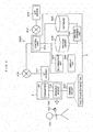
- the server 3 includes a general computer as hardware, receives the sensor data and the work data transmitted from the IoT gateway 201 via the network 202, and performs machine learning. As shown in FIG. 4 , the server 3 includes a control unit 203, a pattern library 204, a database 205, a machine learning unit 206, a determination unit 207, and a display unit 208.
- the control unit 203, the machine learning unit 206, and the determination unit 207 include a CPU or the like as hardware, and control operation of each unit of the server 3 such as storing, in the database 205, the sensor data and the work data received from the sensor device 2 via the network 202.
- the pattern library 204 includes, as hardware, a database stored in a storage device such as an HDD and an SSD, and uses the sensor data and the work data to store a work content or a determination criterion for determining the sensing object 200 as a library.
- Processing performed by the control unit 203, the machine learning unit 206, and the determination unit 207 is implemented by reading a program stored in a read only memory (ROM) (not shown) and loading the program into a random access memory (RAM) (not shown) to execute the program.
- the program may be downloaded from a network, loaded into a memory, and then executed.
- the program may be directly loaded into a memory from a portable computer-readable storage medium such as a compact disk (CD) and a digital versatile disk (DVD) via a reading and writing device that reads information from and writes information into the storage medium, and then the program is executed.
- the program may be provided or distributed by being recorded in the storage medium in a file format that can be installed or executed on a computer.
- the program may be provided or distributed by being stored in a computer connected to a communication network and downloaded via a network. The same may be applied to other embodiments.
- the database 205 is stored in a storage device such as an HDD or an SSD as hardware, and stores the sensor data and the work data transmitted from the IoT gateway 201. Since a data content stored in the database 205 is the same as a data content stored in the data storage unit 107 according to the first embodiment, a description of the data content will be omitted.
- the machine learning unit 206 performs machine learning by collating previous data stored in the database 205 with latest sensor data and work data received from the sensor device 2 at any time, and stores a learning result in the pattern library 204 as the latest sensor data and work data.
- FIG. 5 shows an example of the pattern library 204.
- a type serving as identification information of the wearable sensor 102 provided in the sensor device 2 a tool ID serving as identification information of a tool touched by the wearable sensor 102 of this type, a work ID serving as identification information of work using the tool, and a value of each part of the wearable sensor 102 are stored in association on a work order basis.
- a type serving as identification information of the wearable sensor 102 provided in the sensor device 2 a tool ID serving as identification information of a tool touched by the wearable sensor 102 of this type
- a work ID serving as identification information of work using the tool a value of each part of the wearable sensor 102 are stored in association on a work order basis.
- identification information "type 1" of the glove-shaped wearable sensor 1101 serving as the wearable sensor 102, a work ID “1” of work using the sensor, and tool IDs "1", “2” and “3” of tools that serve as the sensing object 200 used in the work are associated with a value of each part of the wearable sensor 1011 when the tools are used.
- three tools are required when the work having the work ID "1" is performed.
- the index finger base pressure sensor 1102 (ch1), the index finger central pressure sensor 1103 (ch2), the middle finger base pressure sensor 1105 (ch4), the middle finger central pressure sensor 1106 (ch5), the ring finger base pressure sensor 1108 (ch7), and the ring finger central pressure sensor 1109 (ch8), must have detected a pressure equal to or larger than the threshold 1201.
- the pattern library 204 stores, for each wearable sensor and each work serving as a detection target, a pattern indicating a value of each sensor when a piece of work is performed using a wearable sensor.
- the determination unit 207 compares the sensor data and the work data received from the sensor device 2 with data in the pattern library 204 and determines whether a value of each sensor included in the sensor data and the work data matches a value stored in the pattern library 204.
- the determination unit 207 reads identification information (for example, "type 1") of a wearable sensor whose value is determined to be matched with the value stored in the pattern library 204, a work name (for example, a work name "component mounting” corresponding to the ID “1") of work using the sensor, and tool names (for example, “electric jigsaw”, “electric drill”, and “electric screwdriver” corresponding to IDs "1", “2", and “3") of tools serving as sensing objects used in the work, and determines, as a work content, that component mounting work is performed using these tools.
- the determination unit 207 displays the determination result on the display unit 208.
- the determination unit 207 determines that a value of each sensor included in the sensor data and the work data matches a value stored in the pattern library 204, the invention is not limited thereto.
- the determination unit 207 may select data having a closest value.
- the sensor data and the work data obtained from the sensing object 200 include the tool identification information (ID), the ID indicating an installation place of the tool, the user of the tool, the time when the tool is operated, and the like.
- Information such as the tool ID, the ID indicating an installation place of the tool, and the user of the tool is pre-stored in a memory of the tool, and the time when the tool is operated is counted by a timer inside the tool.
- the information may be transmitted from the tool via wireless communication and received by the sensor device 2, or the sensor device 2 may directly read the information.
- An NTP server 2071 is provided in the work information management system 2000, and is connected to the server 3 via the network 202.
- the control unit 203 matches work time included in the sensor data and the work data with time information obtained from the NTP server 2071, and stores the work time in the database 205.
- the determination unit 207 determines whether work is normally performed when the work data collated in the pattern library 204 is transmitted.
- the determination unit 207 determines that an error occurs in the work performed in the subsequent step and outputs to the display unit 208 a fact that the work in the subsequent step is abnormal as a determination result. Similar to the first embodiment, the determination unit 207 may display an advice message on the display unit 208.
- the IoT gateway 201 may be directly connected with the server 203 instead of being connected via the network 202.
- the wearable sensor 102 acquires, from the sensing object 101, work data including identification information of the sensing object 101, a place of the sensing object, a user of the sensing object, and time when the sensing object is operated, and transmits the acquired work data and sensor data to the server 3 in the present embodiment.
- the server 3 determines a work content of the worker based on the sensor data and the work data received from the wearable sensor 102 and the pattern library 204 indicating a pattern of sensor values stored for each wearable sensor 102 and each work.
- a worker and work can be managed by obtaining identification information of a tool, a person, a place, time or the like from the sensor data and the work data, for example, from the sensing object 200, and associating the identification information with each other.
- the server 3 performs machine learning based on previous sensor data and work data received from the wearable sensor 102 and latest sensor data and work data, and sets a result of the machine learning as a new pattern library 204. Accordingly, accuracy of data held by the pattern library 204 can be improved.
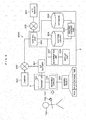
- a work information management system 3000 according to the third embodiment is different from the work information management system 2000 according to the second embodiment in that the work information management system 3000 further includes a camera 300 which is a network camera connected via the network 202.
- the camera 300 may be a stationary camera installed in a workshop, or may be worn on the body of the worker 100. Alternatively, the camera 300 may be integrally formed with the wearable sensor 102.
- the camera 300 captures an image of the worker 100 who works in a workshop, and transmits to the server 3 image data in which the captured image is associated with identification information (ID) of a workshop which is a capturing place and where the camera 300 is installed and identification information (ID) of the camera.
- ID identification information
- a workshop ID and an ID indicating an installation place of a tool are associated with each other in advance to determine which tool is installed in which workshop.
- the control unit 203 of the server 3 When the control unit 203 of the server 3 receives the image data from the camera 300, the control unit 203 stores the image data in the database 205. For example, the control unit 203 searches the database 205 for an ID indicating an installation place of a tool that has the same ID as a workshop ID included in the image data, and associates the searched sensor data and work data with the image data received from the camera 300.
- the work information management system 3000 includes the network camera 300 that captures an image of the worker.
- the camera 300 transmits to the server 3 image data in which the captured image of the worker, identification information indicating a capturing place, and identification information of the camera 300 are associated with each other.
- the server 3 associates work data with the image data based on identification information indicating a place included in the image data received from the camera 300 and a place of the sensing object 101 included in the work data.
- visual information in addition to the sensor data and the work data obtained by the wearable sensor 102 can be collected from the camera 300.
- a worker and work can be managed more accurately by using data obtained from the wearable sensor 102 and data obtained from the camera 300 as complementary information.
- a work information management system 4000 includes, in the sensor device 2, a determination unit 701 and a display unit 702 having the same functions as the determination unit 207 and the display unit 208 shown in FIG. 5 according to the second or third embodiment. Similar to the first embodiment, the display unit 702 may be integrally formed with the wearable sensor, or may be separated from the wearable sensor and connected to the wearable sensor by a wire.
- the transmitter 103 of the sensor device 2 transmits sensor data and work data to the server 3 via the IoT gateway 201, and outputs the sensor data and the work data to the determination unit 701.
- the determination unit 701 receives the sensor data and the work data from the transmitter 103, similar to the determination unit 207, the determination unit 701 compares the sensor data and the work data with a library that is similar to the pattern library 204 that is stored in a memory in the sensor device 2 in advance, and determines whether the sensor data and the work data match the library.
- the determination unit 701 When the sensor data and work data is determined to be matched with the library, the determination unit 701 reads identification information (for example, "type 1") of the wearable sensor, a work name (for example, a work name “component mounting” corresponding to the ID “1") of work using the sensor, and tool names (for example, “electric jigsaw”, “electric drill”, and “electric screwdriver” corresponding to the IDs "1", “2", and “3") of tools serving as sensing objects used in the work, and determines whether component mounting work is performed using these tools.
- the determination unit 701 displays the determination result on the display unit 702 . Similar to the first embodiment, the determination unit 701 may display an advice message on the display unit 702.
- the determination unit 701 and the display unit 702 may be provided at a place other than the worker 100.
- the determination unit 701 and the display unit 702 may be configured such that an administrator other than the worker 100 can visually recognize a work content.
- the determination unit 701 may have a function different from a function of the determination unit 207 in order to transmit different information to the administrator and the worker.
- a determination result of the determination unit 207 may be directly transmitted to and displayed on the display unit 208. Accordingly, the worker 100 can check their own work state information in real time.
- a work information management system 5000 does not include the server 3 or the IoT gateway 201. Instead, data is transmitted from the transmitter 103 to a control unit 502 of a personal computer (PC) 501 via a receiver 500.
- the receiver 500 includes a general communication device as hardware, and may be a modem, a NIC integrally formed with the PC 501, or the like.
- the control unit 502 has the same configuration as the configuration of the control unit 203 of the server 3 shown in FIG. 4 .
- the PC 501 stores sensor data and work data in the database 205.
- the determination unit 701 provided in the sensor device 2 compares the sensor data and the work data received from the transmitter 103 of the sensor device 2 with a library that is similar to the pattern library 204 that is stored in a memory in the sensor device 2 in advance, determines whether the sensor data and the work data match the library, and outputs the determination result. With such a configuration, a worker and work can be managed using a small-scale electronic device or a small investment.
- a work information management system 6000 performs processing on the PC 501.
- the determination unit 701 and the display unit 702 are provided in the PC 501. With such a configuration, the configuration of the sensor device 2 can be made compact. When processing capability of the sensor device 2 is low or in a small appliance in which no space is provided for display, a worker and work can be managed in the same manner as in the embodiments described above.
- the determination unit 701 and the display unit 702 are provided in the PC 501 in FIG. 9
- the determination unit 701 and the display unit 702 may be provided in both the PC 501 and the sensor device 2 as shown in FIG. 7 .
- the seventh embodiment will be described with reference to FIG. 10 .
- the control unit 700, the determination unit 701, and the display unit 702 that perform the same processing as the PC 501 are directly and wirelessly connected to the wearable sensor 102.
- the worker 100 wears the sensor device 2 having such a configuration to work. Accordingly, a worker can manage their own work using an electronic device smaller than electronic devices according to the fifth and sixth embodiments.
- the eighth embodiment will be described with reference to FIG. 11 .
- the eighth embodiment relates to an assistance in acquiring data by the wearable sensor 102 of the sensor device 2 that is used in the work information management systems according to the first to seventh embodiments.
- a case in which the sensing object 101 is a tool is described as an example.
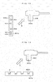
- a sensing assistance 801 is attached to a tool 800 serving as the sensing object 101 in the eighth embodiment so that it is possible to perform the determination.
- a position where the sensing assistance 801 is attached is at, for example, a handle position 804 of the tool 800 that imitates a conductive screwdriver.
- the sensing assistance 801 is formed of a rubber material, a plastic material, a metal material, or the like. Alternatively, the sensing assistance 801 is formed of a material that has a seal-shaped back surface and can be pasted to the tool 800.
- the sensing assistance 801 may be implemented by a member that can be detached from the wearable sensor 102 by a detachment member such as a stopper or Velcro (registered trademark).
- the sensing assistance 801 is provided with concave-convex shaped protrusions 803 within a range of a predetermined position 802.
- parts of the wearable sensor 102 provided at positions corresponding to the protrusions 803 in the predetermined position 802 are pressed against the protrusions 803 to detect a position where the worker holds the tool 800, so that it is easy to determine which tool the worker 100 has taken.
- a sensor at each part of the wearable sensor 102 touches the sensing assistance 801 attached to the sensing object 101. Then, pressures of sensors (for example, three sensors including the index finger tip pressure sensor 1103 (ch3), the middle finger tip pressure sensor 1106 (ch6), and the ring finger tip pressure sensor 1110 (ch9)) at parts corresponding to the protrusions 803 in the predetermined position 802 of the sensing assistance 801 are detected, and the IC chip of the wearable sensor 102 transmits information of these sensors to the terminal device 1.
- Sensor data at this time includes a sensor position corresponding to the protrusion 803 and a pressure value of the sensor in addition to the information shown in FIG. 5 .
- the signal analyzing unit 105 of the terminal device 1 compares pressure values of sensors at these parts with a threshold.
- the signal analyzing unit 105 may display, for example, a value of the index finger base pressure sensor 1102 (ch 1) included in the sensor data received from the sensor device 2 and a position of the index finger base pressure sensor 1102 (ch 1) on the display unit 106, and present an advice message indicating a holding manner to the worker 100.
- the sensing object 101 to which the sensing assistance 801 is attached is not limited to a tool.
- the sensing assistance 801 may be pasted to a desk used in work or a wall at a work site in order to specify the work site.
- the sensing assistance 801 may be attached to the floor of a work site to specify the work site by a wearable sensor on a shoe sole.
- the number of the sensing assistance 801 is not limited to one, and a plurality of sensing assistances 801 may be pasted to one object to be pasted.
- the concave-convex shaped predetermined position 802 may entirely have a concave shape or a convex shape, and include the protrusions 803 in the range of the predetermined position 802.
- the predetermined position 802 is only a design index when the sensing assistance 801 is created. Instead of actually providing the sensing assistance 801, the predetermined position 802 may be directly designed on the sensing object 101 and have the same configuration with the sensing assistance 801.
- the protrusions 803 may have a round shape as shown in FIG. 8 , or may have various shapes such as a square shape, a triangle shape, and a star shape.
- the wearable sensor 102 receives, from the sensing object 101, sensor data obtained by touching the sensing assistance 801 attached to the sensing object 101 in the present embodiment. Accordingly, sensor data can be obtained from various sensing assistances 801 that can be attached to the sensing object 101.
- the wearable sensor 102 receives, from the sensing object 101, sensor data obtained by touching the concave-convex shape provided in each sensing assistance 801.
- the server 3 identifies the sensing object 101 based on a sensor value obtained from the concave-convex shape included in the sensor data.
- the sensing assistance 801 is attached to the sensing object 101, and a shape of the sensing assistance 801 is determined in advance corresponding to a place where the sensing object is placed, a type of the sensing object, and a user of the sensing object.
- the wearable sensor 102 touches the shape of the sensing assistance 801 so as to output sensor data of a touched part.
- a computer such as the server 3 and the PC 501 reads the sensor data, so that the place where the touched sensing object is placed, the type of the sensing object, and the user of the sensing object can be specified.
- the wearable sensor 102 receives the sensor data from the sensing object 101 by pressing the concave-convex shape of the sensing assistance 801, the sensor data can be obtained by, for example, simply holding a tool by the worker.
- a concave-convex shaped predetermined range 802a that is read by the wearable sensor 102 has a long and narrow shape, and is provided with concave-convex shaped protrusions 900 and 901. Since the predetermined range 802a has a long and narrow shape, it is not possible to touch both the protrusion 900 and the protrusion 901 even when, for example, the wearable sensor 102 is pasted to a handle position 804a of the tool 800 and is held by the worker 100 in hand.
- the worker 100 sequentially traces the long and narrow sensing assistance 801a attached to the tool 800 (as indicated by an arrow B in FIG. 12 ) with, for example, a finger wearing the wearable sensor 102, and an IC chip of the wearable sensor 102 reads the concave-convex shape.
- the IC chip of the wearable sensor 102 traces that the sensor device 2 is held by the worker in hand, sensors at each part of the wearable sensor 102 trace the sensing assistance 801 attached to the sensing object 101.
- Sensors for example, the index finger tip pressure sensor 1103 (ch 3), the middle finger tip pressure sensor 1106 (ch 6), and the ring finger tip pressure sensor 1110 (ch 9) at parts positioned corresponding to the protrusions 803 in the predetermined range 802 of the sensing assistance 801 detect pressures in order of the index finger tip pressure sensor 1103 (ch 3), the middle finger tip pressure sensor 1106 (ch 6), and the ring finger tip pressure sensor 1110 (ch 9).
- sensor data at this time includes a sensor position corresponding to the protrusion 803, a pressure value of a sensor, and a time point when a sensor at each part detects a pressure value.
- sensor data at this time includes a sensor position corresponding to the protrusion 803, a pressure value of a sensor, and a time point when a sensor at each part detects a pressure value.
- the signal analyzing unit 105 of the terminal device 1 compares the pressure values of sensors at these parts with a threshold.
- the signal analyzing unit 105 may display, for example, a value of the index finger base pressure sensor 1102 (ch 1) included in the sensor data received from the sensor device 2 and a position of the index finger base pressure sensor 1102 (ch 1) on the display unit 106, and present an advice message indicating a holding manner to the worker 100.
- the signal analyzing unit 105 reads a time point when these parts are traced and a correct order in which each predetermined part is traced, and determines whether each part is traced in the correct order.
- the signal analyzing unit 105 may present an advice message indicating a holding manner to the worker 100.
- the wearable sensor 102 receives the sensor data from the sensing object 101 by tracing the concave-convex shape of the sensing assistance 801 in the present embodiment, the sensor data can be obtained by simply tracing, with a finger even for a tool having a shape that cannot be held or the like.
- Shapes of the protrusions 900 and 901 may include two types of a round shape and a square shape, and the shapes are not limited.
- the wearable sensor 102 may identify the sensing object 101 to which the sensing assistance 801 is pasted based on shapes of the protrusions, or an interval (an interval between positions or time) between a plurality of concave-convex shapes when the sensing object 101 is traced by a finger. For example, data in which the sensing object 101, the sensing assistance 801, and an arrangement of the protrusions provided in the sensing assistance 801 are associated with each other may be stored in a memory of the terminal device 1.
- the signal analyzing unit 105 may compare sensor data obtained from the wearable sensor 102 with the data to determine which sensing object 101 is traced.
- a body that touches the sensing object 101 when the sensing object 101 is traced may be a palm, the back of a hand, an arm, a sole of a foot via a shoe sole, or the like.
- a length of the sensing assistance 801a can be set to any length and the number of protrusion shapes can be set to any number. More information is easily read by the wearable sensor by using the sensing assistance 801a having such a shape as compared with the eighth embodiment.
- FIG. 10 is a side cross-sectional view of a sensing assistance 801b according to the tenth embodiment.
- the sensing assistance 801b is provided with one or plural recesses P and a protrusion 8000 is provided at a bottom of each recess P.
- the sensing assistance 801b is formed of, for example, an elastic material such as rubber that contracts when the material is strongly pressed.
- the sensing assistance 801b is pasted (as indicated by an arrow C in FIG. 13 ) to a handle 804b of the tool 800.
- the hand wearing a wearable sensor does not touch the protrusion 8000.
- a force of a certain level or above is applied to the hand to compress the sensing assistance 801b and touch the protrusion shape 804b.
- the sensing assistance 801b a strength of holding a working object by a worker or a strength of a pressing force when a part of a body presses against the working object can be acquired with good sensitivity by the wearable sensor.
- the eleventh embodiment will be described with reference to FIG. 14 . Similar to the tenth embodiment, the eleventh embodiment relates to an object that acquires a pressing strength of a part of a body such as a hand.
- the eleventh embodiment is different from the tenth embodiment in that heights of protrusions 8000a, 8000b, 8000c, and 8000d in a sensing assistance 801c are different.
- a shape difference of the sensing assistance 801c may be a height difference of the protrusions, a depth difference of the recesses P, or a sharpness difference of tip corners of the protrusions.
- the shape difference of the sensing assistance 801c may be a width difference of the protrusions in a horizontal direction.
- the sensing assistance 801c is pasted (as indicated by an arrow D in FIG. 14 ) to a specified position 804c such as a handle of the tool 800, so that a wearable sensor can accurately determine a holding position of the tool when the worker 100 holds the tool.
- the twelfth embodiment will be described with reference to FIG. 15 .
- the twelfth embodiment relates to a method for using the sensing assistance 801 according to the eighth to eleventh embodiments to identify the worker 100.
- the sensing assistance 801 according to the eighth to eleventh embodiments is attached (as indicated by an arrow E in FIG. 15 ) to an identification medium such as a personal identification ID card 1005 worn by the worker 100 .
- the wearable sensor 102 of the sensor device 2 worn by the worker touches the sensing assistance 801 attached to the ID card 1005.
- the sensing assistance 801 includes the concave-convex shaped protrusions 803 within a range of the predetermined position 802.
- the protrusions 803 are provided at different positions for each worker. Therefore, an IC chip of the wearable sensor 102 reads a pattern indicating positions when the protrusions 803 are traced by the wearable sensor 102 and a time point when each protrusion is traced, and transmits such information to the terminal device 1 as sensor data.
- the signal analyzing unit 105 of the terminal device 1 compares a protrusion arrangement pattern stored in an identification table that is used for identifying a worker and is stored in the data storage unit 107 in advance with the pattern included in the sensor data.
- the protrusion arrangement pattern is stored in association with a worker ID and a name of the worker.
- the signal analyzing unit 105 determines that a worker corresponding to the protrusion arrangement pattern has started working, and outputs the determination result and a time point when each protrusion is traced to the display unit 106 as a work starting time point.
- the signal analyzing unit 105 stores work history data in which the worker ID and the work starting time point are associated with each other in the data storage unit 107 as worker information. Although the work starting time point is described above as an example, the same may be applied to a work ending time point.
Landscapes
- Engineering & Computer Science (AREA)
- Theoretical Computer Science (AREA)
- Physics & Mathematics (AREA)
- General Physics & Mathematics (AREA)
- General Engineering & Computer Science (AREA)
- Business, Economics & Management (AREA)
- Computer Hardware Design (AREA)
- Manufacturing & Machinery (AREA)
- Human Computer Interaction (AREA)
- Health & Medical Sciences (AREA)
- Economics (AREA)
- General Health & Medical Sciences (AREA)
- Human Resources & Organizations (AREA)
- Marketing (AREA)
- Primary Health Care (AREA)
- Strategic Management (AREA)
- Tourism & Hospitality (AREA)
- General Business, Economics & Management (AREA)
- Automation & Control Theory (AREA)
- Quality & Reliability (AREA)
- General Factory Administration (AREA)
- Management, Administration, Business Operations System, And Electronic Commerce (AREA)
Abstract
Description
- The present invention relates to a technique for managing work information of a worker.
- At an assembly work site in a manufacturing industry, it is important to reduce an occurrence of a failure and establish traceability for investigating a cause of the occurrence of a failure in an early stage. A matter for visualizing who performed what kind of work and when the work was performed can be used for the purpose of facilitating training of workers and improving work efficiency at the entire site. At a maintenance site or the like, a matter for associating a tool with a worker is effective in managing articles and recognizing a worker or a work state. When whether work has been performed correctly can be immediately fed back to a worker, quality can be improved and worker safety can be improved.
- Under such a background, with the development of the Internet of Things (IoT) technique in recent years, a method for visualizing work information of a worker in many ways has been proposed, or the technique has been commercialized. In
PTL 1, for example, a wrist band is worn on an arm of a worker who works in an inventory, and a sensor provided on a shelf where articles are stored is used to detect a movement of a hand of the worker. - PTL 1:
US 20170278051 - At a work site or a production site, touching information between a body and the outside may be used in a workable factory in addition to the situation described above. For an article such as fruits that may be damaged by strong gripping, when pressing down a button of a machine or a sensing mechanism for holding the article without impairing the article is confirmed, or when a tool or the like is held in hand, a work state or a worker can be managed if it is possible to know how much strength should be used to hold what kind of tool or confirm that the article is held when the article has a characteristic shape.
- It is difficult to acquire information on touching strength when touching the article with the body in such a manner or information of a surface concave-convex state by using the method disclosed in
PTL 1 or from an image of a camera or the like. On the other hand, the information can be collected by, for example, wearing on the body a pressure sensor or a wearable object such as a piece of clothing to which the pressure sensor is attached. However, an article such as a tool generally has a unique shape or surface state, and it is difficult to determine what a touched object is like only from a sensor worn on the body. - An object of the invention is to provide a technique capable of performing work information management by associating a worker with a work content by the worker touching a sensing object via a wearable sensor.
- The work information management system according to the invention preferably includes a wearable sensor including a sensor that is worn by a worker and receives sensor data from a sensing object and a transmitter that transmits the sensor data received by the sensor to a terminal, and a computer that determines a work content of the worker based on the sensor data received from the wearable sensor and outputs a determination result to a display unit.
- The invention is also known as a work information management method performed by the work information management system described above.
- According to an aspect of the invention, work information can be managed by associating a worker with a work content by the worker touching a sensing object via a wearable sensor.
-
- [
FIG. 1] FIG. 1 shows a schematic configuration of a work information management system. - [
FIG. 2] FIG. 2 shows a configuration example of a sensor device and a sensing object when a signal analyzing unit analyzes sensor data. - [
FIG. 3] FIG. 3 shows an example of the sensor data. - [
FIG. 4] FIG. 4 shows a system configuration example of a work information management system. - [
FIG. 5] FIG. 5 shows an example of a pattern library. - [
FIG. 6] FIG. 6 shows a system configuration example of a work information management system in cooperation with a camera. - [
FIG. 7] FIG. 7 shows a system configuration example of a work information management system using a wearable sensor including a determination unit and a display unit. - [
FIG. 8] FIG. 8 shows a system configuration example of a work information management system including a wearable sensor and a single PC. - [
FIG. 9] FIG. 9 shows a system configuration example of a work information management system including a wearable sensor and a function of executing data storage, an analysis, and a display by a single PC. - [
FIG. 10] FIG. 10 shows a system configuration example of a work information management system that performs data shaping and result determination inside a wearable sensor. - [
FIG. 11] FIG. 11 shows an example of a sensing assistance attached to a sensing object by a wearable sensor. - [
FIG. 12] FIG. 12 shows an example of a sensing assistance that obtains identification information by tracing a body wearing a wearable sensor. - [
FIG. 13] FIG. 13 shows an example of a sensing assistance having a devised shape so that a wearable sensor responds when being pressed by a body with a strength of a certain level or above. - [
FIG. 14] FIG. 14 shows an example of a sensing assistance having a devised shape so that a wearable sensor responds when being pressed by a body with different strengths corresponding to respective structures. - [
FIG. 15] FIG. 15 shows an example of a sensing assistance that is devised so that the sensing assistance can be identified by a wearable sensor attached to a personal authentication card of a worker. - Hereinafter, embodiments will be described in detail with reference to the drawings. However, the invention should not be construed as being limited to the description of the embodiments described below. Those skilled in the art could easily understand that specific configurations can be changed without departing from the spirit or scope of the invention.
- In configurations according to the invention described below, the same or similar functions are denoted by the same reference numerals in different drawings, and repetitive descriptions may be omitted.
- In the present specification, expressions such as "first", "second", and "third" are used to identify components, and do not necessarily limit a number or an order. Numbers for identifying components may be used on a context basis, and a number used in one context may not necessarily indicate the same configuration in another context. A component identified by a certain number is not prevented from having a function of a component identified by another number.
- In order to facilitate understanding of the invention, positions, sizes, shapes, ranges, or the like of each configuration shown in the drawings may not represent actual positions, sizes, shapes, ranges, and the like. Therefore, the invention is not necessarily limited to the positions, the sizes, the shapes, the ranges, and the like shown in the drawings.
- Components described in a singular form in the present specification include components in a plural form unless specifically stated otherwise.
- Although an application example of work in a manufacturing industry or at a maintenance site will be described in the following embodiments, the application of the invention is not necessarily limited thereto. Although an example of work performed by hands will be mainly described in the following embodiments, a wearable sensor included in the invention is not limited thereto. The wearable sensor may be worn on a part of a foot such as a sole of a foot and a knee, or a part of an arm such as a shoulder or an elbow. In the following embodiments, an example of a mechanism for a worker to acquire data by touching with a part of a body includes a pressure sensor that is mounted to a wearable sensor. The pressure sensor may have a plastic shape, or a cloth shape.
- The first embodiment will be described with reference to
FIG. 1 . A workinformation management system 1000 according to the first embodiment includes aterminal device 1 and asensor device 2. Theterminal device 1 includes a general computer as hardware, receives sensor data from thesensor device 2, and analyzes the sensor data. As shown inFIG. 1 , theterminal device 1 includes areceiver 104, asignal analyzing unit 105, adisplay unit 106, and adata storage unit 107. Thesensor device 2 includes, as hardware, an object (for example, a glove or a shoe provided with a pressure sensor) such as an appliance, a machine, a tool, or a device that is provided with awearable sensor 102 and atransmitter 103. Thesensor device 2 acquires sensor data from thewearable sensor 102, and thetransmitter 103 transmits the sensor data to theterminal device 1. As shown inFIG. 1 , thesensor device 2 includes thewearable sensor 102 and thetransmitter 103. - The
receiver 104 in theterminal device 1 includes a general communication device (for example, a network interface card (NIC)) as hardware, and receives the sensor data from thesensor device 2. Thesignal analyzing unit 105 includes a general arithmetic device (for example, a central processing unit (CPU)) as hardware. Thesignal analyzing unit 105 analyzes the sensor data, displays the sensor data and an analysis result of the sensor data on thedisplay unit 106, and stores the sensor data and the analysis result of the sensor data in thedata storage unit 107. Thedata storage unit 107 includes a general storage device (for example, a hard disk drive (HDD) or a solid state drive (SSD)) as hardware, and stores the analysis result of the sensor data from thesignal analyzing unit 105. Thedisplay unit 106 includes a general display (for example, a liquid crystal display (LCD)) as hardware, and displays the analysis result of the sensor data from thesignal analyzing unit 105. - The
wearable sensor 102 has a glove shape or the like, and is a device that is internally provided with a sensing device. Alternatively, thewearable sensor 102 may have a cap shape worn on a fingertip, or a shape covering parts of a palm or a back of a hand. Aworker 100 grips asensing object 101 or touches a surface of thesensing object 101 with a tip of a hand, or presses thesensing object 101 with a part of the hand, so that thewearable sensor 102 provided in thesensor device 2 obtains sensor data. Thesensing object 101 may be a tool, an electric machine, or the like used by theworker 100 during working. Alternatively, thesensing object 101 may be a conveying object such as a trolley or food such as fruits. In addition to a sensor that senses an object by touching the object, thewearable sensor 102 may include a sensor such as a sound sensor, a vibration sensor, and a magnetic sensor at the same time. Thetransmitter 103 may be integrally formed in thewearable sensor 102. Thetransmitter 103 maybe provided in thewearable sensor 102 through a wire for transferring power or an electrical signal. - The
receiver 104 receives an electrical signal including sensor data that is wirelessly transmitted from thetransmitter 103. Thesignal analyzing unit 105 reads, from the received electrical signal, the sensor data of thesensing object 101 taken by theworker 100 in hand or touched by theworker 100 with hand, and determines a work content of the worker such as how theworker 100 touches thesensing object 101. -
FIG. 2 shows a configuration example of the sensor device and the sensing object when thesignal analyzing unit 105 analyzes the sensor data.FIG. 3 shows an example of the sensor data analyzed by thesignal analyzing unit 105. - As shown in
FIG. 2 , thewearable sensor 102 in thesensor device 2 is a glove-shapedwearable sensor 1101 that can be worn on a hand of theworker 100, and includes one or plural sensors provided at one or plural parts where theworker 100 touches thesensing object 101. The glove-shapedwearable sensor 1101 includes an index finger base pressure sensor 1102 (ch 1), an index finger central pressure sensor 1103 (ch 2), an index finger tip pressure sensor 1104 (ch 3), a middle finger base pressure sensor 1105 (ch 4), a middle finger central pressure sensor 1106 (ch 5), a middle finger tip pressure sensor 1107 (ch 6), a ring finger base pressure sensor 1108 (ch 7), a ring finger central pressure sensor 1109 (ch 8), and a ring finger tip pressure sensor 1110 (ch 9). Thesensing object 101 is an electric tool or the like held by theworker 100 when cutting a work material. - In such a configuration, the
sensor device 2 reads a pressure signal detected by a pressure sensor in each part of thewearable sensor 1101, and transmits information serving as sensor data to theterminal device 1 via thetransmitter 103. The sensor data includes a pressure value, identification information for identifying thewearable sensor 1101 and a pressure sensor, and a time point when the pressure value is detected. -
FIG. 3 shows an example of the sensor data. As shown inFIG. 3 , information in the sensor data indicates a temporal transition of pressure values included in detection signals detected by the wearable sensor. The information is transmitted to each wearable sensor.FIG. 3 shows that the index finger base pressure sensor 1102 (ch 1), the middle finger central pressure sensor 1106 (ch 5), the ring finger tip pressure sensor 1110 (ch 9), and the like detected pressure exceeding apredetermined threshold 1201 used in pressure evaluation at atime point 1200 indicating a moment when theworker 100 holds a tool. Although pressure values of the other pressure sensors increase at thetime point 1200 indicating a moment when theworker 100 holds a tool, the pressure values do not exceed thethreshold 1201. Therefore, thesignal analyzing unit 105 determines that thesensing object 101 is gripped by an index finger base, a middle finger center, and a ring finger tip as a work content of theworker 100, and outputs the determination result as an analysis result. For example, thesignal analyzing unit 105 outputs to the display unit 106 a message indicating that thesensing object 101 is gripped by the index finger base, the middle finger center, and the ring finger tip, pressure values when thesensing object 101 is gripped, and a time point. At this time, thesignal analyzing unit 105 may compare the above-described sensor data used when determining the work content with reference sensor data that defines a criterion to be satisfied in the work, determine whether the sensor data satisfies the reference sensor data, and output a determination result and an analysis result to thedisplay unit 106. The reference sensor data may be pre-stored in thedata storage unit 107 on a work basis. With such a configuration, an administrator can easily determine what kind of work state the worker is in, what kind of work content is performed, and whether the work content satisfies a criterion. - The sensor data obtained by touching may not be a pressure value and may be, for example, a level indicating a strength at which the
sensing object 101 is touched by the wearable sensor 120. Alternatively, the sensor data may be a change rate of a touching strength indicating how the touching strength changes within a certain period of time. - The
display unit 106 may be provided in thesensor device 2 and may be implemented to be directly visible to theworker 100. Alternatively, thedisplay unit 106 may include a monitor that is checked by another person such as an administrator at a position away from theworker 100 or checked by both the administrator and theworker 100. Thesignal analyzing unit 105 may transmit an analysis result to the monitor via wireless communication to display the analysis result. A content displayed as the analysis result may relate to sensor data in real time when theworker 100 works. Alternatively, the content displayed as the analysis result may be a result obtained by comparing the sensor data in real time when theworker 100 works with sensor data of previous work, or a result obtained by analyzing the previous work. In this case, a change in a degree of proficiency of the worker or the like can be known by comparing sensor data during current work of theworker 100 with sensor data during previous work of theworker 100. - The
display unit 106 may only display visual information, or may display a combination of tactile information such as sound and vibration and visual information. In addition, thedisplay unit 106 may only display tactile information instead of visual information, or may display information obtained by the worker or a person other than the worker. The same may be applied to the second and subsequent embodiments. - When there are a plurality of workers, the
data storage unit 107 stores sensor data of thesensing object 101 touched by eachworker 100 for each part of thewearable sensor 102. Thedata storage unit 107 stores work data of a working object serving as thesensing object 101 corresponding to the sensor data. The work data includes time spent on the work, a date and time when the work is performed, a worker ID for identifying theworker 100, and the like. The IC chip provided in thewearable sensor 102 of thesensor device 2 transmits the time spent on the work, the date and time when the work is performed, and the worker ID to theterminal device 1 as the work data. For example, the IC chip counts a period of time from a time point when thewearable sensor 102 detects pressure up to a time point when thewearable sensor 102 detects no pressure. The period of time may serve as the time spent on the work. The IC chip reads a current time point counted by a timer (not shown) . The current time point may serve as the date and time when the work is performed. The worker ID may be a worker ID obtained by the IC chip reading a worker ID pre-stored in a memory (not shown) of theworker 100 who uses thesensor device 2. - Data stored in the
data storage unit 107 may be the sensor data received by thereceiver 104 of theterminal device 1, or an analysis result of thesignal analyzing unit 105, or both the analysis result and the sensor data. Thedata storage unit 107 may temporarily store real-time sensor data received from thesensor device 2 by thereceiver 104 at any time, or may continue storing previous sensor data. Thedata storage unit 107 may store data in an electronic medium, or may print data on a printing medium. - As described above, the work information management system according to the present embodiment includes the
sensor device 2 and theterminal device 1. Thesensor device 2 includes a sensor that is worn by a worker and receives sensor data from thesensing object 101, and thewearable sensor 102 that includes thetransmitter 103 that transmits the sensor data received from the sensor to theterminal device 1. Theterminal device 1 determines a work content of the worker based on the sensor data received from thewearable sensor 102 and outputs the determination result to thedisplay unit 106. Accordingly, the work content of the worker can be easily known using thesensor device 2. - In such a work information management system, work information of the worker can be associated with a working object by using the sensor data and the work data, and a work history and a work content, for example, when and where the worker performs what kind of work, can be managed. That is, work on a working obj ect can be detected or estimated by a worker touching the working object, and work information can be managed by associating the worker with a work content according to the detection or estimation.
- For example, a supervisor of the
worker 100 may use thesensor device 2 to touch thesensing object 101, and sensor data indicating a correct touching manner of thesensing object 101 may be stored in thedata storage unit 107 in advance as a model. Then, thesignal analyzing unit 105 compares sensor data obtained when theworker 100 works with the model to determine a deviation degree between the sensor data and the model, and displays an analysis result on thedisplay unit 106, so that a correct using manner of thesensing object 101 can be taught to theworker 100. For example, when a value of the index finger base pressure sensor 1102 (ch 1) included in the sensor data received from thesensor device 2 is smaller than a correct value of the index finger base pressure sensor included in the sensor data indicating the correct touching manner by a predetermined value, thesignal analyzing unit 105 displays, on thedisplay unit 106, an advice message such as "a holding manner of the index finger is weak, please hold a litter stronger". - The second embodiment will be described with reference to
FIG. 4 . A workinformation management system 2000 according to the second embodiment has a more specific device configuration than the workinformation management system 100 according to the first embodiment. Thework management system 2000 includes thesensor device 2 the same as the sensor device in the first embodiment, anIoT gateway 201, and aserver 3. Compared with thesensing object 100 according to the first embodiment, asensing object 200 is implemented by an object (for example, a tool that can store information and count time) that can obtain work data such as sensing object identification information (ID), ID indicating an installation place of the sensing object, a user of the sensing object, and time when the sensing object is operated. Work data according to the present embodiment may include the work data according to the first embodiment. - The
IoT gateway 201 includes a general communication computer (for example, a gateway server) as hardware, and performs data shaping to transmit a wireless signal including sensor data transmitted from thetransmitter 103 to anetwork 202. - The
server 3 includes a general computer as hardware, receives the sensor data and the work data transmitted from theIoT gateway 201 via thenetwork 202, and performs machine learning. As shown inFIG. 4 , theserver 3 includes acontrol unit 203, apattern library 204, adatabase 205, amachine learning unit 206, adetermination unit 207, and adisplay unit 208. - The
control unit 203, themachine learning unit 206, and thedetermination unit 207 include a CPU or the like as hardware, and control operation of each unit of theserver 3 such as storing, in thedatabase 205, the sensor data and the work data received from thesensor device 2 via thenetwork 202. Thepattern library 204 includes, as hardware, a database stored in a storage device such as an HDD and an SSD, and uses the sensor data and the work data to store a work content or a determination criterion for determining thesensing object 200 as a library. - Processing performed by the
control unit 203, themachine learning unit 206, and thedetermination unit 207 is implemented by reading a program stored in a read only memory (ROM) (not shown) and loading the program into a random access memory (RAM) (not shown) to execute the program. The program may be downloaded from a network, loaded into a memory, and then executed. Alternatively, the program may be directly loaded into a memory from a portable computer-readable storage medium such as a compact disk (CD) and a digital versatile disk (DVD) via a reading and writing device that reads information from and writes information into the storage medium, and then the program is executed. The program may be provided or distributed by being recorded in the storage medium in a file format that can be installed or executed on a computer. The program may be provided or distributed by being stored in a computer connected to a communication network and downloaded via a network. The same may be applied to other embodiments. - The
database 205 is stored in a storage device such as an HDD or an SSD as hardware, and stores the sensor data and the work data transmitted from theIoT gateway 201. Since a data content stored in thedatabase 205 is the same as a data content stored in thedata storage unit 107 according to the first embodiment, a description of the data content will be omitted. - The
machine learning unit 206 performs machine learning by collating previous data stored in thedatabase 205 with latest sensor data and work data received from thesensor device 2 at any time, and stores a learning result in thepattern library 204 as the latest sensor data and work data. -
FIG. 5 shows an example of thepattern library 204. InFIG. 5 , a type serving as identification information of thewearable sensor 102 provided in thesensor device 2, a tool ID serving as identification information of a tool touched by thewearable sensor 102 of this type, a work ID serving as identification information of work using the tool, and a value of each part of thewearable sensor 102 are stored in association on a work order basis. InFIG. 5 , for example, it can be seen that identification information "type 1" of the glove-shapedwearable sensor 1101 serving as thewearable sensor 102, a work ID "1" of work using the sensor, and tool IDs "1", "2" and "3" of tools that serve as thesensing object 200 used in the work are associated with a value of each part of the wearable sensor 1011 when the tools are used. In this example, three tools (tool IDs "1", "2", and "3") are required when the work having the work ID "1" is performed. When the work is performed using the tool having the tool ID "1", three sensors, that is, the index finger tip pressure sensor 1103 (ch 3), the middle finger tip pressure sensor 1106 (ch 6), and the ring finger tip pressure sensor 1110 (ch 9), must have detected a pressure equal to or larger than thethreshold 1201. When the work is performed using the tool having the tool ID "2", three sensors, that is, the index finger base pressure sensor 1102 (ch 1), the middle finger base pressure sensor 1105 (ch 4), and the ring finger base pressure sensor 1108 (ch 7), must have detected a pressure equal to or larger than thethreshold 1201. When the work is performed using the tool having the tool ID "3", six sensors, that is, the index finger base pressure sensor 1102 (ch1), the index finger central pressure sensor 1103 (ch2), the middle finger base pressure sensor 1105 (ch4), the middle finger central pressure sensor 1106 (ch5), the ring finger base pressure sensor 1108 (ch7), and the ring finger central pressure sensor 1109 (ch8), must have detected a pressure equal to or larger than thethreshold 1201. - In this manner, the
pattern library 204 stores, for each wearable sensor and each work serving as a detection target, a pattern indicating a value of each sensor when a piece of work is performed using a wearable sensor. Thedetermination unit 207 compares the sensor data and the work data received from thesensor device 2 with data in thepattern library 204 and determines whether a value of each sensor included in the sensor data and the work data matches a value stored in thepattern library 204. Then, thedetermination unit 207 reads identification information (for example, "type 1") of a wearable sensor whose value is determined to be matched with the value stored in thepattern library 204, a work name (for example, a work name "component mounting" corresponding to the ID "1") of work using the sensor, and tool names (for example, "electric jigsaw", "electric drill", and "electric screwdriver" corresponding to IDs "1", "2", and "3") of tools serving as sensing objects used in the work, and determines, as a work content, that component mounting work is performed using these tools. Thedetermination unit 207 displays the determination result on thedisplay unit 208. Although a case is described above in which thedetermination unit 207 determines that a value of each sensor included in the sensor data and the work data matches a value stored in thepattern library 204, the invention is not limited thereto. Thedetermination unit 207 may select data having a closest value. - The sensor data and the work data obtained from the
sensing object 200 include the tool identification information (ID), the ID indicating an installation place of the tool, the user of the tool, the time when the tool is operated, and the like. Information such as the tool ID, the ID indicating an installation place of the tool, and the user of the tool is pre-stored in a memory of the tool, and the time when the tool is operated is counted by a timer inside the tool. The information may be transmitted from the tool via wireless communication and received by thesensor device 2, or thesensor device 2 may directly read the information. - An NTP server 2071 is provided in the work
information management system 2000, and is connected to theserver 3 via thenetwork 202. Thecontrol unit 203 matches work time included in the sensor data and the work data with time information obtained from the NTP server 2071, and stores the work time in thedatabase 205. Thedetermination unit 207 determines whether work is normally performed when the work data collated in thepattern library 204 is transmitted. In a case in which the work is determined to be normal or above normal, for example, when a deviation degree between a value of each sensor included in the sensor data and the work data at the time of performing actual work and the data stored in the pattern library is equal to or larger than a certain value (for example, when a sensor value in a first step at the time of performing certain work matches the data stored in the pattern library while a sensor value in a subsequent step cannot be obtained), thedetermination unit 207 determines that an error occurs in the work performed in the subsequent step and outputs to the display unit 208 a fact that the work in the subsequent step is abnormal as a determination result. Similar to the first embodiment, thedetermination unit 207 may display an advice message on thedisplay unit 208. - In the second and subsequent embodiments, the
IoT gateway 201 may be directly connected with theserver 203 instead of being connected via thenetwork 202. - As described above, the
wearable sensor 102 acquires, from thesensing object 101, work data including identification information of thesensing object 101, a place of the sensing object, a user of the sensing object, and time when the sensing object is operated, and transmits the acquired work data and sensor data to theserver 3 in the present embodiment. Theserver 3 determines a work content of the worker based on the sensor data and the work data received from thewearable sensor 102 and thepattern library 204 indicating a pattern of sensor values stored for eachwearable sensor 102 and each work. With such a work information management system, a worker and work can be managed by obtaining identification information of a tool, a person, a place, time or the like from the sensor data and the work data, for example, from thesensing object 200, and associating the identification information with each other. - The
server 3 performs machine learning based on previous sensor data and work data received from thewearable sensor 102 and latest sensor data and work data, and sets a result of the machine learning as anew pattern library 204. Accordingly, accuracy of data held by thepattern library 204 can be improved. - As shown in
FIG. 6 , a workinformation management system 3000 according to the third embodiment is different from the workinformation management system 2000 according to the second embodiment in that the workinformation management system 3000 further includes acamera 300 which is a network camera connected via thenetwork 202. Thecamera 300 may be a stationary camera installed in a workshop, or may be worn on the body of theworker 100. Alternatively, thecamera 300 may be integrally formed with thewearable sensor 102. Thecamera 300 captures an image of theworker 100 who works in a workshop, and transmits to theserver 3 image data in which the captured image is associated with identification information (ID) of a workshop which is a capturing place and where thecamera 300 is installed and identification information (ID) of the camera. A workshop ID and an ID indicating an installation place of a tool are associated with each other in advance to determine which tool is installed in which workshop. - When the
control unit 203 of theserver 3 receives the image data from thecamera 300, thecontrol unit 203 stores the image data in thedatabase 205. For example, thecontrol unit 203 searches thedatabase 205 for an ID indicating an installation place of a tool that has the same ID as a workshop ID included in the image data, and associates the searched sensor data and work data with the image data received from thecamera 300. - As described above, the work
information management system 3000 according to the present embodiment includes thenetwork camera 300 that captures an image of the worker. Thecamera 300 transmits to theserver 3 image data in which the captured image of the worker, identification information indicating a capturing place, and identification information of thecamera 300 are associated with each other. Theserver 3 associates work data with the image data based on identification information indicating a place included in the image data received from thecamera 300 and a place of thesensing object 101 included in the work data. - With such a configuration, visual information in addition to the sensor data and the work data obtained by the
wearable sensor 102 can be collected from thecamera 300. A worker and work can be managed more accurately by using data obtained from thewearable sensor 102 and data obtained from thecamera 300 as complementary information. - As shown in
FIG. 7 , a workinformation management system 4000 according to the fourth embodiment includes, in thesensor device 2, adetermination unit 701 and adisplay unit 702 having the same functions as thedetermination unit 207 and thedisplay unit 208 shown inFIG. 5 according to the second or third embodiment. Similar to the first embodiment, thedisplay unit 702 may be integrally formed with the wearable sensor, or may be separated from the wearable sensor and connected to the wearable sensor by a wire. - The
transmitter 103 of thesensor device 2 transmits sensor data and work data to theserver 3 via theIoT gateway 201, and outputs the sensor data and the work data to thedetermination unit 701. When thedetermination unit 701 receives the sensor data and the work data from thetransmitter 103, similar to thedetermination unit 207, thedetermination unit 701 compares the sensor data and the work data with a library that is similar to thepattern library 204 that is stored in a memory in thesensor device 2 in advance, and determines whether the sensor data and the work data match the library. When the sensor data and work data is determined to be matched with the library, thedetermination unit 701 reads identification information (for example, "type 1") of the wearable sensor, a work name (for example, a work name "component mounting" corresponding to the ID "1") of work using the sensor, and tool names (for example, "electric jigsaw", "electric drill", and "electric screwdriver" corresponding to the IDs "1", "2", and "3") of tools serving as sensing objects used in the work, and determines whether component mounting work is performed using these tools. Thedetermination unit 701 displays the determination result on thedisplay unit 702 . Similar to the first embodiment, thedetermination unit 701 may display an advice message on thedisplay unit 702. - The
determination unit 701 and thedisplay unit 702 may be provided at a place other than theworker 100. For example, thedetermination unit 701 and thedisplay unit 702 may be configured such that an administrator other than theworker 100 can visually recognize a work content. Thedetermination unit 701 may have a function different from a function of thedetermination unit 207 in order to transmit different information to the administrator and the worker. As a system configuration, a determination result of thedetermination unit 207 may be directly transmitted to and displayed on thedisplay unit 208. Accordingly, theworker 100 can check their own work state information in real time. - The fifth embodiment will be described with reference to
FIG. 8 . Different from the second to fourth embodiments, a workinformation management system 5000 according to the fifth embodiment does not include theserver 3 or theIoT gateway 201. Instead, data is transmitted from thetransmitter 103 to acontrol unit 502 of a personal computer (PC) 501 via areceiver 500. Thereceiver 500 includes a general communication device as hardware, and may be a modem, a NIC integrally formed with thePC 501, or the like. Thecontrol unit 502 has the same configuration as the configuration of thecontrol unit 203 of theserver 3 shown inFIG. 4 . - Similar to the
server 3, thePC 501 stores sensor data and work data in thedatabase 205. On the other hand, similar to the fourth embodiment, thedetermination unit 701 provided in thesensor device 2 compares the sensor data and the work data received from thetransmitter 103 of thesensor device 2 with a library that is similar to thepattern library 204 that is stored in a memory in thesensor device 2 in advance, determines whether the sensor data and the work data match the library, and outputs the determination result. With such a configuration, a worker and work can be managed using a small-scale electronic device or a small investment. - The sixth embodiment will be described with reference to
FIG. 9 . Similar to the fifth embodiment, a workinformation management system 6000 according to the sixth embodiment performs processing on thePC 501. On the other hand, similar to the case shown inFIG. 4 , thedetermination unit 701 and thedisplay unit 702 are provided in thePC 501. With such a configuration, the configuration of thesensor device 2 can be made compact. When processing capability of thesensor device 2 is low or in a small appliance in which no space is provided for display, a worker and work can be managed in the same manner as in the embodiments described above. Although thedetermination unit 701 and thedisplay unit 702 are provided in thePC 501 inFIG. 9 , thedetermination unit 701 and thedisplay unit 702 may be provided in both thePC 501 and thesensor device 2 as shown inFIG. 7 . - The seventh embodiment will be described with reference to
FIG. 10 . In a workinformation management system 7000 according to the seventh embodiment, thecontrol unit 700, thedetermination unit 701, and thedisplay unit 702 that perform the same processing as thePC 501 are directly and wirelessly connected to thewearable sensor 102. Theworker 100 wears thesensor device 2 having such a configuration to work. Accordingly, a worker can manage their own work using an electronic device smaller than electronic devices according to the fifth and sixth embodiments. - The eighth embodiment will be described with reference to
FIG. 11 . The eighth embodiment relates to an assistance in acquiring data by thewearable sensor 102 of thesensor device 2 that is used in the work information management systems according to the first to seventh embodiments. A case in which thesensing object 101 is a tool is described as an example. When there are a plurality of tools having the same shape at a work site, it is difficult or impossible to use the method according to the seventh embodiment described above to determine which one of the plurality of tools theworker 100 has taken. Asensing assistance 801 is attached to atool 800 serving as thesensing object 101 in the eighth embodiment so that it is possible to perform the determination. A position where thesensing assistance 801 is attached is at, for example, ahandle position 804 of thetool 800 that imitates a conductive screwdriver. - The
sensing assistance 801 is formed of a rubber material, a plastic material, a metal material, or the like. Alternatively, thesensing assistance 801 is formed of a material that has a seal-shaped back surface and can be pasted to thetool 800. Thesensing assistance 801 may be implemented by a member that can be detached from thewearable sensor 102 by a detachment member such as a stopper or Velcro (registered trademark). - The
sensing assistance 801 is provided with concave-convex shapedprotrusions 803 within a range of apredetermined position 802. When theworker 100 takes thetool 800 to which thesensing assistance 801 is attached (indicated by an arrow A inFIG. 11 ), parts of thewearable sensor 102 provided at positions corresponding to theprotrusions 803 in thepredetermined position 802 are pressed against theprotrusions 803 to detect a position where the worker holds thetool 800, so that it is easy to determine which tool theworker 100 has taken. - For example, when the worker holds the
sensor device 2 in hand, a sensor at each part of thewearable sensor 102 touches thesensing assistance 801 attached to thesensing object 101. Then, pressures of sensors (for example, three sensors including the index finger tip pressure sensor 1103 (ch3), the middle finger tip pressure sensor 1106 (ch6), and the ring finger tip pressure sensor 1110 (ch9)) at parts corresponding to theprotrusions 803 in thepredetermined position 802 of thesensing assistance 801 are detected, and the IC chip of thewearable sensor 102 transmits information of these sensors to theterminal device 1. Sensor data at this time includes a sensor position corresponding to theprotrusion 803 and a pressure value of the sensor in addition to the information shown inFIG. 5 . For example, at a moment when theworker 100 holds a tool, a pressure of a pressure sensor provided in the glove-shaped wearable sensor increases in each channel. On the other hand, pressures of sensors (for example, the above-described three sensors) positioned corresponding to theprotrusions 803 change particularly greatly. Therefore, similar to the first embodiment, thesignal analyzing unit 105 of theterminal device 1 compares pressure values of sensors at these parts with a threshold. When a difference between the pressure values and the threshold is equal to or larger than a certain value, thesignal analyzing unit 105 may display, for example, a value of the index finger base pressure sensor 1102 (ch 1) included in the sensor data received from thesensor device 2 and a position of the index finger base pressure sensor 1102 (ch 1) on thedisplay unit 106, and present an advice message indicating a holding manner to theworker 100. - The
sensing object 101 to which thesensing assistance 801 is attached is not limited to a tool. For example, thesensing assistance 801 may be pasted to a desk used in work or a wall at a work site in order to specify the work site. Thesensing assistance 801 may be attached to the floor of a work site to specify the work site by a wearable sensor on a shoe sole. The number of thesensing assistance 801 is not limited to one, and a plurality ofsensing assistances 801 may be pasted to one object to be pasted. The concave-convex shapedpredetermined position 802 may entirely have a concave shape or a convex shape, and include theprotrusions 803 in the range of thepredetermined position 802. Thepredetermined position 802 is only a design index when thesensing assistance 801 is created. Instead of actually providing thesensing assistance 801, thepredetermined position 802 may be directly designed on thesensing object 101 and have the same configuration with thesensing assistance 801. Theprotrusions 803 may have a round shape as shown inFIG. 8 , or may have various shapes such as a square shape, a triangle shape, and a star shape. - As described above, the
wearable sensor 102 receives, from thesensing object 101, sensor data obtained by touching thesensing assistance 801 attached to thesensing object 101 in the present embodiment. Accordingly, sensor data can be obtained fromvarious sensing assistances 801 that can be attached to thesensing object 101. - The
wearable sensor 102 receives, from thesensing object 101, sensor data obtained by touching the concave-convex shape provided in eachsensing assistance 801. Theserver 3 identifies thesensing object 101 based on a sensor value obtained from the concave-convex shape included in the sensor data. For example, thesensing assistance 801 is attached to thesensing object 101, and a shape of thesensing assistance 801 is determined in advance corresponding to a place where the sensing object is placed, a type of the sensing object, and a user of the sensing object. Thewearable sensor 102 touches the shape of thesensing assistance 801 so as to output sensor data of a touched part. A computer such as theserver 3 and thePC 501 reads the sensor data, so that the place where the touched sensing object is placed, the type of the sensing object, and the user of the sensing object can be specified. - Since the
wearable sensor 102 receives the sensor data from thesensing object 101 by pressing the concave-convex shape of thesensing assistance 801, the sensor data can be obtained by, for example, simply holding a tool by the worker. - The ninth embodiment will be described with reference to
FIG. 12 . Similar to the eighth embodiment, the ninth embodiment relates to a sensing assistance. In asensing assistance 801a according to the ninth embodiment, a concave-convex shapedpredetermined range 802a that is read by thewearable sensor 102 has a long and narrow shape, and is provided with concave-convex shapedprotrusions predetermined range 802a has a long and narrow shape, it is not possible to touch both theprotrusion 900 and theprotrusion 901 even when, for example, thewearable sensor 102 is pasted to ahandle position 804a of thetool 800 and is held by theworker 100 in hand. According to the ninth embodiment, theworker 100 sequentially traces the long andnarrow sensing assistance 801a attached to the tool 800 (as indicated by an arrow B inFIG. 12 ) with, for example, a finger wearing thewearable sensor 102, and an IC chip of thewearable sensor 102 reads the concave-convex shape. Specifically, similar to the eighth embodiment, when the IC chip of thewearable sensor 102 traces that thesensor device 2 is held by the worker in hand, sensors at each part of thewearable sensor 102 trace thesensing assistance 801 attached to thesensing object 101. Sensors (for example, the index finger tip pressure sensor 1103 (ch 3), the middle finger tip pressure sensor 1106 (ch 6), and the ring finger tip pressure sensor 1110 (ch 9)) at parts positioned corresponding to theprotrusions 803 in thepredetermined range 802 of thesensing assistance 801 detect pressures in order of the index finger tip pressure sensor 1103 (ch 3), the middle finger tip pressure sensor 1106 (ch 6), and the ring finger tip pressure sensor 1110 (ch 9). - The IC chip of the
wearable sensor 102 transmits information to theterminal device 1. In addition to the information shown inFIG. 5 , sensor data at this time includes a sensor position corresponding to theprotrusion 803, a pressure value of a sensor, and a time point when a sensor at each part detects a pressure value. For example, when theworker 100 traces a tool, pressures of pressure sensors provided in the glove-shaped wearable sensor increase in each channel in a tracing order. On the other hand, pressures of sensors (for example, the above-described three sensors) positioned corresponding to theprotrusions 803 change particularly greatly in the tracing order. Therefore, similar to the first embodiment, thesignal analyzing unit 105 of theterminal device 1 compares the pressure values of sensors at these parts with a threshold. When a difference between the pressure values and the threshold is equal to or larger than a certain value, thesignal analyzing unit 105 may display, for example, a value of the index finger base pressure sensor 1102 (ch 1) included in the sensor data received from thesensor device 2 and a position of the index finger base pressure sensor 1102 (ch 1) on thedisplay unit 106, and present an advice message indicating a holding manner to theworker 100. Thesignal analyzing unit 105 reads a time point when these parts are traced and a correct order in which each predetermined part is traced, and determines whether each part is traced in the correct order. When thesignal analyzing unit 105 determines that each part is not traced in the correct order, thesignal analyzing unit 105 may present an advice message indicating a holding manner to theworker 100. - As described above, since the
wearable sensor 102 receives the sensor data from thesensing object 101 by tracing the concave-convex shape of thesensing assistance 801 in the present embodiment, the sensor data can be obtained by simply tracing, with a finger even for a tool having a shape that cannot be held or the like. - Shapes of the
protrusions wearable sensor 102 may identify thesensing object 101 to which thesensing assistance 801 is pasted based on shapes of the protrusions, or an interval (an interval between positions or time) between a plurality of concave-convex shapes when thesensing object 101 is traced by a finger. For example, data in which thesensing object 101, thesensing assistance 801, and an arrangement of the protrusions provided in thesensing assistance 801 are associated with each other may be stored in a memory of theterminal device 1. Thesignal analyzing unit 105 may compare sensor data obtained from thewearable sensor 102 with the data to determine whichsensing object 101 is traced. - In addition to a finger, a body that touches the
sensing object 101 when thesensing object 101 is traced may be a palm, the back of a hand, an arm, a sole of a foot via a shoe sole, or the like. A length of thesensing assistance 801a can be set to any length and the number of protrusion shapes can be set to any number. More information is easily read by the wearable sensor by using thesensing assistance 801a having such a shape as compared with the eighth embodiment. - The tenth embodiment will be described with reference to
FIG. 13 . Similar to the eighth and ninth embodiments, the tenth embodiment relates to a sensing assistance.FIG. 10 is a side cross-sectional view of asensing assistance 801b according to the tenth embodiment. Thesensing assistance 801b is provided with one or plural recesses P and aprotrusion 8000 is provided at a bottom of each recess P. Thesensing assistance 801b is formed of, for example, an elastic material such as rubber that contracts when the material is strongly pressed. For example, thesensing assistance 801b is pasted (as indicated by an arrow C inFIG. 13 ) to ahandle 804b of thetool 800. When theworker 100 holds thetool 800 in hand and a holding force is weak, the hand wearing a wearable sensor does not touch theprotrusion 8000. A force of a certain level or above is applied to the hand to compress thesensing assistance 801b and touch theprotrusion shape 804b. With thesensing assistance 801b, a strength of holding a working object by a worker or a strength of a pressing force when a part of a body presses against the working object can be acquired with good sensitivity by the wearable sensor. - The eleventh embodiment will be described with reference to
FIG. 14 . Similar to the tenth embodiment, the eleventh embodiment relates to an object that acquires a pressing strength of a part of a body such as a hand. The eleventh embodiment is different from the tenth embodiment in that heights of protrusions 8000a, 8000b, 8000c, and 8000d in asensing assistance 801c are different. A shape difference of thesensing assistance 801c may be a height difference of the protrusions, a depth difference of the recesses P, or a sharpness difference of tip corners of the protrusions. Alternatively, the shape difference of thesensing assistance 801c may be a width difference of the protrusions in a horizontal direction. Thesensing assistance 801c is pasted (as indicated by an arrow D inFIG. 14 ) to a specifiedposition 804c such as a handle of thetool 800, so that a wearable sensor can accurately determine a holding position of the tool when theworker 100 holds the tool. - The twelfth embodiment will be described with reference to
FIG. 15 . The twelfth embodiment relates to a method for using thesensing assistance 801 according to the eighth to eleventh embodiments to identify theworker 100. According to the twelfth embodiment, thesensing assistance 801 according to the eighth to eleventh embodiments is attached (as indicated by an arrow E inFIG. 15 ) to an identification medium such as a personalidentification ID card 1005 worn by theworker 100 . When theworker 100 wears thesensor device 2 provided with thewearable sensor 102 at the time of starting work, at a first hour of starting work of a day, or the like, a part of a body touches thewearable sensor 102 of thesensor device 2 worn by theworker 100 at thesensing assistance 801 provided on thecard 1005. Accordingly, worker information can be directly registered in the work information management system according to the first to seventh embodiments. - For example, the
wearable sensor 102 of thesensor device 2 worn by the worker touches thesensing assistance 801 attached to theID card 1005. Thesensing assistance 801 includes the concave-convex shapedprotrusions 803 within a range of thepredetermined position 802. Theprotrusions 803 are provided at different positions for each worker. Therefore, an IC chip of thewearable sensor 102 reads a pattern indicating positions when theprotrusions 803 are traced by thewearable sensor 102 and a time point when each protrusion is traced, and transmits such information to theterminal device 1 as sensor data. Thesignal analyzing unit 105 of theterminal device 1 compares a protrusion arrangement pattern stored in an identification table that is used for identifying a worker and is stored in thedata storage unit 107 in advance with the pattern included in the sensor data. - In the identification table, the protrusion arrangement pattern is stored in association with a worker ID and a name of the worker. When the pattern included in the sensor data matches the protrusion arrangement pattern, the
signal analyzing unit 105 determines that a worker corresponding to the protrusion arrangement pattern has started working, and outputs the determination result and a time point when each protrusion is traced to thedisplay unit 106 as a work starting time point. Thesignal analyzing unit 105 stores work history data in which the worker ID and the work starting time point are associated with each other in thedata storage unit 107 as worker information. Although the work starting time point is described above as an example, the same may be applied to a work ending time point. -
- 1: terminal device
- 2: sensor device
- 1000, 2000, 3000, 4000, 5000, 6000, 7000: work information management system
- 100: worker
- 101: sensing object
- 102: wearable sensor
- 103: transmitter
- 104: receiver
- 105: signal analyzing unit
- 106, 106a, 106b, 106c: display unit
- 107: data storage unit
- 200: identification ID
- 201: IoT gateway
- 202: router
- 203: server
- 204: pattern library
- 205: database
- 206: machine learning unit
- 2071: NTP server
- 208, 208a, 208b, 208c: determination unit
- 300: camera
- 500: receiver
- 501: PC
- 502: control unit
- 700: control unit
- 800: tool
- 801, 801a, 801b, 801c: sensing assistance
- 803: protrusion
- 900a, 900b, 900c: round sensing assistance having concave and convex
- 8000, 8000a, 8000b, 8000c, 8000d: protrusion
- 1005: personal identification ID card
Claims (12)
- A work information management system comprising:a wearable sensor including a sensor that is worn by a worker and receives sensor data from a sensing object and a transmitter that transmits the sensor data received from the sensor to a terminal; anda computer that determines a work content of the worker based on the sensor data received from the wearable sensor and outputs a determination result to a display unit.
- The work information management system according to claim 1, wherein
the wearable sensor acquires, from the sensing object, work data including identification information of the sensing object, a place of the sensing object, a user of the sensing object, and time when the sensing object is operated, and transmits the acquired work data and the sensor data to the computer, and
the computer determines the work content of the worker based on the sensor data and the work data received from the wearable sensor and a pattern library indicating a pattern of sensor values stored for each wearable sensor and each work. - The work information management system according to claim 2, wherein
the computer performs machine learning based on previous sensor data and work data received from the wearable sensor and latest sensor data and work data, and sets a result of the machine learning as a latest pattern library. - The work information management system according to claim 2, further comprising:a camera that captures an image of the worker, whereinthe camera transmits, to the computer, image data in which the captured image of the worker, identification information indicating a capturing place, and identification information of the camera are associated with each other, andthe computer associates the work data with the image data based on the identification information indicating the place included in the image data received from the camera and the place of the sensing object included in the work data.
- The work information management system according to claim 1, wherein
the wearable sensor is provided in a glove-shaped appliance that can be worn by the worker, and
the wearable sensor receives the sensor data by touching the sensing object by each part of a finger, a palm, or a back of a hand of the worker. - The work information management system according to claim 5, wherein
the wearable sensor receives the sensor data by touching the sensing object by a pressure sensor provided at each part. - The work information management system according to claim 1, wherein
the wearable sensor receives, from the sensing object, the sensor data obtained by touching a sensing assistance attached to the sensing object. - The work information management system according to claim 7, wherein
the wearable sensor receives, from the sensing object, the sensor data obtained by touching a concave-convex shape provided for each sensing assistance, and
the computer identifies the sensing object based on a sensor value obtained by touching the concave-convex shape included in the sensor data. - The work information management system according to claim 8, wherein
the wearable sensor receives the sensor data from the sensing object by pressing the concave-convex shape of the sensing assistance. - The work information management system according to claim 8, wherein
the wearable sensor receives the sensor data from the sensing object by tracing the concave-convex shape of the sensing assistance. - The work information management system according to claim 1, wherein
the wearable sensor is provided on a sock worn by the worker or a shoe-shaped wearable object worn by the worker on a body, and the sensor data is received from the sensing object by touching the wearable object at a sole side or an instep side of the worker. - A work information management method comprising:receiving sensor data from a sensing object by a wearable sensor worn by a worker;transmitting the received sensor data to a terminal by the wearable sensor;determining a work content of the worker by a computer based on the sensor data received from the wearable sensor; andoutputting a determination result to a display unit by the computer.
Applications Claiming Priority (1)
| Application Number | Priority Date | Filing Date | Title |
|---|---|---|---|
| PCT/JP2018/028441 WO2020026299A1 (en) | 2018-07-30 | 2018-07-30 | Operation information management system, and operation information management method |
Publications (3)
| Publication Number | Publication Date |
|---|---|
| EP3832582A1 true EP3832582A1 (en) | 2021-06-09 |
| EP3832582A4 EP3832582A4 (en) | 2022-03-09 |
| EP3832582B1 EP3832582B1 (en) | 2025-03-05 |
Family
ID=69230614
Family Applications (1)
| Application Number | Title | Priority Date | Filing Date |
|---|---|---|---|
| EP18928250.2A Active EP3832582B1 (en) | 2018-07-30 | 2018-07-30 | Work information management system and work information management method |
Country Status (4)
| Country | Link |
|---|---|
| US (1) | US11508018B2 (en) |
| EP (1) | EP3832582B1 (en) |
| JP (1) | JP7118155B2 (en) |
| WO (1) | WO2020026299A1 (en) |
Families Citing this family (10)
| Publication number | Priority date | Publication date | Assignee | Title |
|---|---|---|---|---|
| CN115699064B (en) * | 2020-06-18 | 2025-10-14 | 三菱电机株式会社 | Work assisting device and work assisting method |
| JP7654983B2 (en) * | 2021-01-22 | 2025-04-02 | オムロン株式会社 | WORK ESTIMATION DEVICE, CONTROL METHOD FOR WORK ESTIMATION DEVICE, INFORMATION PROCESSING PROGRAM, AND RECORDING MEDIUM |
| JP7816859B2 (en) * | 2021-03-26 | 2026-02-18 | ミルウォーキー エレクトリック ツール コーポレイション | Power tools with configurable motor stator windings |
| CN117043565A (en) * | 2021-04-13 | 2023-11-10 | 三菱电机株式会社 | Contact information acquisition device, contact information acquisition system, contact information acquisition method, and contact information acquisition program |
| EP4235493A4 (en) | 2021-04-22 | 2024-09-18 | Samsung Electronics Co., Ltd. | ELECTRONIC DEVICE FOR CHECKING THE CONNECTION OF A CONNECTOR AND OPERATING METHOD THEREFOR |
| US12115612B2 (en) * | 2021-05-21 | 2024-10-15 | Gryp Technologies Inc. | Method and system for cueing a user of a tool |
| DE102021126552B4 (en) | 2021-10-13 | 2025-09-04 | Workaround Gmbh | Glove and wearable sensor device comprising a glove and an electronic module |
| DE102022132061A1 (en) | 2022-12-02 | 2024-06-13 | Workaround Gmbh | Glove and portable device |
| DE102023118306A1 (en) | 2023-07-11 | 2025-01-16 | Workaround Gmbh | Electrical circuit assembly for a glove |
| JP2025181268A (en) * | 2024-05-31 | 2025-12-11 | 株式会社日立製作所 | Work information management system and work information management method |
Family Cites Families (21)
| Publication number | Priority date | Publication date | Assignee | Title |
|---|---|---|---|---|
| JPS56125691A (en) | 1980-03-07 | 1981-10-02 | Hitachi Ltd | Intermediate slab executing method of nuclear reactor base |
| US20020075232A1 (en) * | 1997-08-15 | 2002-06-20 | Wolfgang Daum | Data glove |
| US7080322B2 (en) * | 1998-12-18 | 2006-07-18 | Tangis Corporation | Thematic response to a computer user's context, such as by a wearable personal computer |
| US20050013416A1 (en) * | 2003-07-16 | 2005-01-20 | Lee David E. | Telephone communication system with safety features |
| DE102005018527A1 (en) | 2005-04-20 | 2006-10-26 | David Bauer | Golf training gloves |
| JP2009048581A (en) | 2007-08-23 | 2009-03-05 | Fuji Xerox Co Ltd | Process management system |
| JP5215331B2 (en) * | 2010-02-03 | 2013-06-19 | トヨタ自動車東日本株式会社 | Work determination system, work determination method, and recording medium recording the work determination method |
| US20120211560A1 (en) * | 2011-02-23 | 2012-08-23 | Penn Hsiao Su | Ordering System Using Radio Frequency Identification |
| US9554732B2 (en) * | 2014-06-30 | 2017-01-31 | Everyday Olympian, Inc. | Modular physical activity monitoring system |
| US20180227735A1 (en) * | 2014-08-25 | 2018-08-09 | Phyziio, Inc. | Proximity-Based Attribution of Rewards |
| DE102015017432B4 (en) * | 2014-10-11 | 2023-12-28 | Workaround Gmbh | Work clothing unit, glove, sensor module and structural unit |
| US9861151B2 (en) * | 2014-12-05 | 2018-01-09 | SaPHIBeat Technologies, Inc. | Activity monitoring systems and methods for accident detection and response |
| US9881276B2 (en) | 2016-03-28 | 2018-01-30 | Amazon Technologies, Inc. | Ultrasonic bracelet and receiver for detecting position in 2D plane |
| US9870717B2 (en) * | 2016-03-30 | 2018-01-16 | Hcl Technologies Limited | Assisting a visually impaired user to grip an object |
| US10296768B2 (en) * | 2016-05-18 | 2019-05-21 | International Business Machines Corporation | Tracking objects in a two dimensional space |
| DE112017004499T5 (en) * | 2016-09-07 | 2019-06-19 | Tactual Labs Co. | PRESSURE AND SHEAR SENSOR |
| CN108021104A (en) | 2016-10-31 | 2018-05-11 | 博世汽车部件(苏州)有限公司 | Production line monitoring system and method |
| JP2018157985A (en) * | 2017-03-23 | 2018-10-11 | セイコーエプソン株式会社 | Motion analysis apparatus, motion analysis system, and motion analysis method |
| US10180721B2 (en) * | 2017-06-14 | 2019-01-15 | Apple Inc. | Fabric-based devices with force sensing |
| US10275083B2 (en) * | 2017-09-20 | 2019-04-30 | Alex Hamid Mani | Assistive device with a refreshable haptic feedback interface |
| JP6321879B1 (en) | 2017-12-20 | 2018-05-09 | グレイステクノロジー株式会社 | Work support system and work support program |
-
2018
- 2018-07-30 EP EP18928250.2A patent/EP3832582B1/en active Active
- 2018-07-30 JP JP2020533900A patent/JP7118155B2/en active Active
- 2018-07-30 US US16/970,717 patent/US11508018B2/en active Active
- 2018-07-30 WO PCT/JP2018/028441 patent/WO2020026299A1/en not_active Ceased
Also Published As
| Publication number | Publication date |
|---|---|
| JPWO2020026299A1 (en) | 2020-12-17 |
| JP7118155B2 (en) | 2022-08-15 |
| US11508018B2 (en) | 2022-11-22 |
| US20210056646A1 (en) | 2021-02-25 |
| EP3832582A4 (en) | 2022-03-09 |
| EP3832582B1 (en) | 2025-03-05 |
| WO2020026299A1 (en) | 2020-02-06 |
Similar Documents
| Publication | Publication Date | Title |
|---|---|---|
| EP3832582B1 (en) | Work information management system and work information management method | |
| US12137759B2 (en) | Hand-worn workwear unit for scanning barcodes | |
| CN113631901B (en) | Work content detection and determination device and work content detection and determination system | |
| JP6710644B2 (en) | Motion analysis device, motion analysis method and program | |
| JP7171359B2 (en) | Work information management system and wearable sensor | |
| US10383322B2 (en) | Fishing and sailing activity detection | |
| US20160174897A1 (en) | Sensor Embedded Wearable Technology Glove | |
| JP6546907B2 (en) | Integrated data collection and reporting interface for devices | |
| EP2678757B1 (en) | Gesture recognition system | |
| EP2849035A1 (en) | Information processing device, information processing method, and program | |
| US20110144543A1 (en) | Behavior recognition apparatus | |
| US11756326B2 (en) | Keepout zone detection and active safety system | |
| JP6733995B2 (en) | Work analysis device, work analysis method, and program | |
| AU2018204669B2 (en) | Monitors for movements of workers | |
| JP6596309B2 (en) | Analysis apparatus and analysis method | |
| KR102206712B1 (en) | Worker management device | |
| JP6676321B2 (en) | Applicability evaluation device and adaptability evaluation method | |
| CN102609117A (en) | Mouse with self management function and management method of mouse | |
| JP2017148220A (en) | Biological information measurement system and method | |
| US20190122767A1 (en) | System, devices, and methods for coding and decoding motion activity and for detecting change in such | |
| JP2011186693A (en) | Information input apparatus | |
| JP5891265B2 (en) | Feeding motion analysis device, feeding motion analysis system, feeding motion analysis method, and program | |
| CN112783879A (en) | Data processing method, device and system based on data platform and storage medium | |
| US12629055B1 (en) | Systems and methods for tracking physical work activity | |
| KR20190034981A (en) | Operation method of wearable pointing device in work field |
Legal Events
| Date | Code | Title | Description |
|---|---|---|---|
| STAA | Information on the status of an ep patent application or granted ep patent |
Free format text: STATUS: THE INTERNATIONAL PUBLICATION HAS BEEN MADE |
|
| PUAI | Public reference made under article 153(3) epc to a published international application that has entered the european phase |
Free format text: ORIGINAL CODE: 0009012 |
|
| STAA | Information on the status of an ep patent application or granted ep patent |
Free format text: STATUS: REQUEST FOR EXAMINATION WAS MADE |
|
| 17P | Request for examination filed |
Effective date: 20210301 |
|
| AK | Designated contracting states |
Kind code of ref document: A1 Designated state(s): AL AT BE BG CH CY CZ DE DK EE ES FI FR GB GR HR HU IE IS IT LI LT LU LV MC MK MT NL NO PL PT RO RS SE SI SK SM TR |
|
| DAV | Request for validation of the european patent (deleted) | ||
| DAX | Request for extension of the european patent (deleted) | ||
| A4 | Supplementary search report drawn up and despatched |
Effective date: 20220208 |
|
| RIC1 | Information provided on ipc code assigned before grant |
Ipc: G06Q 10/08 20120101ALN20220202BHEP Ipc: G06F 3/147 20060101ALN20220202BHEP Ipc: G06F 3/01 20060101ALI20220202BHEP Ipc: G05B 19/418 20060101ALI20220202BHEP Ipc: G06Q 50/04 20120101AFI20220202BHEP |
|
| STAA | Information on the status of an ep patent application or granted ep patent |
Free format text: STATUS: EXAMINATION IS IN PROGRESS |
|
| 17Q | First examination report despatched |
Effective date: 20230915 |
|
| GRAJ | Information related to disapproval of communication of intention to grant by the applicant or resumption of examination proceedings by the epo deleted |
Free format text: ORIGINAL CODE: EPIDOSDIGR1 |
|
| STAA | Information on the status of an ep patent application or granted ep patent |
Free format text: STATUS: GRANT OF PATENT IS INTENDED |
|
| GRAC | Information related to communication of intention to grant a patent modified |
Free format text: ORIGINAL CODE: EPIDOSCIGR1 |
|
| GRAJ | Information related to disapproval of communication of intention to grant by the applicant or resumption of examination proceedings by the epo deleted |
Free format text: ORIGINAL CODE: EPIDOSDIGR1 |
|
| GRAP | Despatch of communication of intention to grant a patent |
Free format text: ORIGINAL CODE: EPIDOSNIGR1 |
|
| STAA | Information on the status of an ep patent application or granted ep patent |
Free format text: STATUS: EXAMINATION IS IN PROGRESS |
|
| RIC1 | Information provided on ipc code assigned before grant |
Ipc: G06Q 10/08 20120101ALN20240814BHEP Ipc: G06F 3/147 20060101ALN20240814BHEP Ipc: G06Q 10/087 20230101ALI20240814BHEP Ipc: G06F 3/01 20060101ALI20240814BHEP Ipc: G05B 19/418 20060101ALI20240814BHEP Ipc: G06Q 50/04 20120101AFI20240814BHEP |
|
| GRAP | Despatch of communication of intention to grant a patent |
Free format text: ORIGINAL CODE: EPIDOSNIGR1 |
|
| STAA | Information on the status of an ep patent application or granted ep patent |
Free format text: STATUS: GRANT OF PATENT IS INTENDED |
|
| INTG | Intention to grant announced |
Effective date: 20240910 |
|
| RIC1 | Information provided on ipc code assigned before grant |
Ipc: G06Q 10/08 20120101ALN20240902BHEP Ipc: G06F 3/147 20060101ALN20240902BHEP Ipc: G06Q 10/087 20230101ALI20240902BHEP Ipc: G06F 3/01 20060101ALI20240902BHEP Ipc: G05B 19/418 20060101ALI20240902BHEP Ipc: G06Q 50/04 20120101AFI20240902BHEP |
|
| INTC | Intention to grant announced (deleted) | ||
| INTG | Intention to grant announced |
Effective date: 20240924 |
|
| RIC1 | Information provided on ipc code assigned before grant |
Ipc: G06Q 10/08 20120101ALN20240916BHEP Ipc: G06F 3/147 20060101ALN20240916BHEP Ipc: G06Q 10/087 20230101ALI20240916BHEP Ipc: G06F 3/01 20060101ALI20240916BHEP Ipc: G05B 19/418 20060101ALI20240916BHEP Ipc: G06Q 50/04 20120101AFI20240916BHEP |
|
| GRAS | Grant fee paid |
Free format text: ORIGINAL CODE: EPIDOSNIGR3 |
|
| GRAA | (expected) grant |
Free format text: ORIGINAL CODE: 0009210 |
|
| STAA | Information on the status of an ep patent application or granted ep patent |
Free format text: STATUS: THE PATENT HAS BEEN GRANTED |
|
| AK | Designated contracting states |
Kind code of ref document: B1 Designated state(s): AL AT BE BG CH CY CZ DE DK EE ES FI FR GB GR HR HU IE IS IT LI LT LU LV MC MK MT NL NO PL PT RO RS SE SI SK SM TR |
|
| REG | Reference to a national code |
Ref country code: GB Ref legal event code: FG4D |
|
| REG | Reference to a national code |
Ref country code: CH Ref legal event code: EP |
|
| REG | Reference to a national code |
Ref country code: DE Ref legal event code: R096 Ref document number: 602018079952 Country of ref document: DE |
|
| REG | Reference to a national code |
Ref country code: IE Ref legal event code: FG4D |
|
| PG25 | Lapsed in a contracting state [announced via postgrant information from national office to epo] |
Ref country code: RS Free format text: LAPSE BECAUSE OF FAILURE TO SUBMIT A TRANSLATION OF THE DESCRIPTION OR TO PAY THE FEE WITHIN THE PRESCRIBED TIME-LIMIT Effective date: 20250605 |
|
| PG25 | Lapsed in a contracting state [announced via postgrant information from national office to epo] |
Ref country code: FI Free format text: LAPSE BECAUSE OF FAILURE TO SUBMIT A TRANSLATION OF THE DESCRIPTION OR TO PAY THE FEE WITHIN THE PRESCRIBED TIME-LIMIT Effective date: 20250305 |
|
| REG | Reference to a national code |
Ref country code: NL Ref legal event code: MP Effective date: 20250305 |
|
| PG25 | Lapsed in a contracting state [announced via postgrant information from national office to epo] |
Ref country code: ES Free format text: LAPSE BECAUSE OF FAILURE TO SUBMIT A TRANSLATION OF THE DESCRIPTION OR TO PAY THE FEE WITHIN THE PRESCRIBED TIME-LIMIT Effective date: 20250305 |
|
| REG | Reference to a national code |
Ref country code: LT Ref legal event code: MG9D |
|
| PG25 | Lapsed in a contracting state [announced via postgrant information from national office to epo] |
Ref country code: NO Free format text: LAPSE BECAUSE OF FAILURE TO SUBMIT A TRANSLATION OF THE DESCRIPTION OR TO PAY THE FEE WITHIN THE PRESCRIBED TIME-LIMIT Effective date: 20250605 |
|
| PG25 | Lapsed in a contracting state [announced via postgrant information from national office to epo] |
Ref country code: HR Free format text: LAPSE BECAUSE OF FAILURE TO SUBMIT A TRANSLATION OF THE DESCRIPTION OR TO PAY THE FEE WITHIN THE PRESCRIBED TIME-LIMIT Effective date: 20250305 |
|
| PG25 | Lapsed in a contracting state [announced via postgrant information from national office to epo] |
Ref country code: LV Free format text: LAPSE BECAUSE OF FAILURE TO SUBMIT A TRANSLATION OF THE DESCRIPTION OR TO PAY THE FEE WITHIN THE PRESCRIBED TIME-LIMIT Effective date: 20250305 |
|
| PG25 | Lapsed in a contracting state [announced via postgrant information from national office to epo] |
Ref country code: GR Free format text: LAPSE BECAUSE OF FAILURE TO SUBMIT A TRANSLATION OF THE DESCRIPTION OR TO PAY THE FEE WITHIN THE PRESCRIBED TIME-LIMIT Effective date: 20250606 Ref country code: BG Free format text: LAPSE BECAUSE OF FAILURE TO SUBMIT A TRANSLATION OF THE DESCRIPTION OR TO PAY THE FEE WITHIN THE PRESCRIBED TIME-LIMIT Effective date: 20250305 |
|
| REG | Reference to a national code |
Ref country code: AT Ref legal event code: MK05 Ref document number: 1773627 Country of ref document: AT Kind code of ref document: T Effective date: 20250305 |
|
| PG25 | Lapsed in a contracting state [announced via postgrant information from national office to epo] |
Ref country code: NL Free format text: LAPSE BECAUSE OF FAILURE TO SUBMIT A TRANSLATION OF THE DESCRIPTION OR TO PAY THE FEE WITHIN THE PRESCRIBED TIME-LIMIT Effective date: 20250305 |
|
| PG25 | Lapsed in a contracting state [announced via postgrant information from national office to epo] |
Ref country code: SE Free format text: LAPSE BECAUSE OF FAILURE TO SUBMIT A TRANSLATION OF THE DESCRIPTION OR TO PAY THE FEE WITHIN THE PRESCRIBED TIME-LIMIT Effective date: 20250305 |
|
| PG25 | Lapsed in a contracting state [announced via postgrant information from national office to epo] |
Ref country code: SM Free format text: LAPSE BECAUSE OF FAILURE TO SUBMIT A TRANSLATION OF THE DESCRIPTION OR TO PAY THE FEE WITHIN THE PRESCRIBED TIME-LIMIT Effective date: 20250305 |
|
| PG25 | Lapsed in a contracting state [announced via postgrant information from national office to epo] |
Ref country code: PT Free format text: LAPSE BECAUSE OF FAILURE TO SUBMIT A TRANSLATION OF THE DESCRIPTION OR TO PAY THE FEE WITHIN THE PRESCRIBED TIME-LIMIT Effective date: 20250707 |
|
| PGFP | Annual fee paid to national office [announced via postgrant information from national office to epo] |
Ref country code: DE Payment date: 20250731 Year of fee payment: 8 |
|
| PG25 | Lapsed in a contracting state [announced via postgrant information from national office to epo] |
Ref country code: PL Free format text: LAPSE BECAUSE OF FAILURE TO SUBMIT A TRANSLATION OF THE DESCRIPTION OR TO PAY THE FEE WITHIN THE PRESCRIBED TIME-LIMIT Effective date: 20250305 Ref country code: IT Free format text: LAPSE BECAUSE OF FAILURE TO SUBMIT A TRANSLATION OF THE DESCRIPTION OR TO PAY THE FEE WITHIN THE PRESCRIBED TIME-LIMIT Effective date: 20250305 |
|
| PG25 | Lapsed in a contracting state [announced via postgrant information from national office to epo] |
Ref country code: AT Free format text: LAPSE BECAUSE OF FAILURE TO SUBMIT A TRANSLATION OF THE DESCRIPTION OR TO PAY THE FEE WITHIN THE PRESCRIBED TIME-LIMIT Effective date: 20250305 |
|
| PG25 | Lapsed in a contracting state [announced via postgrant information from national office to epo] |
Ref country code: CZ Free format text: LAPSE BECAUSE OF FAILURE TO SUBMIT A TRANSLATION OF THE DESCRIPTION OR TO PAY THE FEE WITHIN THE PRESCRIBED TIME-LIMIT Effective date: 20250305 Ref country code: EE Free format text: LAPSE BECAUSE OF FAILURE TO SUBMIT A TRANSLATION OF THE DESCRIPTION OR TO PAY THE FEE WITHIN THE PRESCRIBED TIME-LIMIT Effective date: 20250305 |
|
| PG25 | Lapsed in a contracting state [announced via postgrant information from national office to epo] |
Ref country code: RO Free format text: LAPSE BECAUSE OF FAILURE TO SUBMIT A TRANSLATION OF THE DESCRIPTION OR TO PAY THE FEE WITHIN THE PRESCRIBED TIME-LIMIT Effective date: 20250305 |
|
| PG25 | Lapsed in a contracting state [announced via postgrant information from national office to epo] |
Ref country code: SK Free format text: LAPSE BECAUSE OF FAILURE TO SUBMIT A TRANSLATION OF THE DESCRIPTION OR TO PAY THE FEE WITHIN THE PRESCRIBED TIME-LIMIT Effective date: 20250305 |
|
| PG25 | Lapsed in a contracting state [announced via postgrant information from national office to epo] |
Ref country code: IS Free format text: LAPSE BECAUSE OF FAILURE TO SUBMIT A TRANSLATION OF THE DESCRIPTION OR TO PAY THE FEE WITHIN THE PRESCRIBED TIME-LIMIT Effective date: 20250705 |
|
| REG | Reference to a national code |
Ref country code: DE Ref legal event code: R097 Ref document number: 602018079952 Country of ref document: DE |
|
| PLBE | No opposition filed within time limit |
Free format text: ORIGINAL CODE: 0009261 |
|
| STAA | Information on the status of an ep patent application or granted ep patent |
Free format text: STATUS: NO OPPOSITION FILED WITHIN TIME LIMIT |
|
| PG25 | Lapsed in a contracting state [announced via postgrant information from national office to epo] |
Ref country code: DK Free format text: LAPSE BECAUSE OF FAILURE TO SUBMIT A TRANSLATION OF THE DESCRIPTION OR TO PAY THE FEE WITHIN THE PRESCRIBED TIME-LIMIT Effective date: 20250305 |
|
| REG | Reference to a national code |
Ref country code: CH Ref legal event code: L10 Free format text: ST27 STATUS EVENT CODE: U-0-0-L10-L00 (AS PROVIDED BY THE NATIONAL OFFICE) Effective date: 20260114 |
|
| 26N | No opposition filed |
Effective date: 20251208 |
|
| REG | Reference to a national code |
Ref country code: CH Ref legal event code: H13 Free format text: ST27 STATUS EVENT CODE: U-0-0-H10-H13 (AS PROVIDED BY THE NATIONAL OFFICE) Effective date: 20260224 |
|
| PG25 | Lapsed in a contracting state [announced via postgrant information from national office to epo] |
Ref country code: LU Free format text: LAPSE BECAUSE OF NON-PAYMENT OF DUE FEES Effective date: 20250730 |
|
| GBPC | Gb: european patent ceased through non-payment of renewal fee |
Effective date: 20250730 |
|
| REG | Reference to a national code |
Ref country code: BE Ref legal event code: MM Effective date: 20250731 |
|
| PG25 | Lapsed in a contracting state [announced via postgrant information from national office to epo] |
Ref country code: GB Free format text: LAPSE BECAUSE OF NON-PAYMENT OF DUE FEES Effective date: 20250730 |
|
| PG25 | Lapsed in a contracting state [announced via postgrant information from national office to epo] |
Ref country code: BE Free format text: LAPSE BECAUSE OF NON-PAYMENT OF DUE FEES Effective date: 20250731 |
|
| PG25 | Lapsed in a contracting state [announced via postgrant information from national office to epo] |
Ref country code: FR Free format text: LAPSE BECAUSE OF NON-PAYMENT OF DUE FEES Effective date: 20250731 |
|
| PG25 | Lapsed in a contracting state [announced via postgrant information from national office to epo] |
Ref country code: CH Free format text: LAPSE BECAUSE OF NON-PAYMENT OF DUE FEES Effective date: 20250731 |