EP3832550B1 - Vorrichtung und verfahren zum trainieren eines klassifikators - Google Patents
Vorrichtung und verfahren zum trainieren eines klassifikators Download PDFInfo
- Publication number
- EP3832550B1 EP3832550B1 EP19212867.6A EP19212867A EP3832550B1 EP 3832550 B1 EP3832550 B1 EP 3832550B1 EP 19212867 A EP19212867 A EP 19212867A EP 3832550 B1 EP3832550 B1 EP 3832550B1
- Authority
- EP
- European Patent Office
- Prior art keywords
- classifier
- classifications
- actuator
- metric
- player
- Prior art date
- Legal status (The legal status is an assumption and is not a legal conclusion. Google has not performed a legal analysis and makes no representation as to the accuracy of the status listed.)
- Active
Links
Images



Classifications
-
- G—PHYSICS
- G06—COMPUTING OR CALCULATING; COUNTING
- G06N—COMPUTING ARRANGEMENTS BASED ON SPECIFIC COMPUTATIONAL MODELS
- G06N3/00—Computing arrangements based on biological models
- G06N3/02—Neural networks
- G06N3/08—Learning methods
-
- G—PHYSICS
- G06—COMPUTING OR CALCULATING; COUNTING
- G06F—ELECTRIC DIGITAL DATA PROCESSING
- G06F18/00—Pattern recognition
- G06F18/20—Analysing
- G06F18/24—Classification techniques
- G06F18/241—Classification techniques relating to the classification model, e.g. parametric or non-parametric approaches
- G06F18/2411—Classification techniques relating to the classification model, e.g. parametric or non-parametric approaches based on the proximity to a decision surface, e.g. support vector machines
-
- A—HUMAN NECESSITIES
- A63—SPORTS; GAMES; AMUSEMENTS
- A63F—CARD, BOARD, OR ROULETTE GAMES; INDOOR GAMES USING SMALL MOVING PLAYING BODIES; VIDEO GAMES; GAMES NOT OTHERWISE PROVIDED FOR
- A63F13/00—Video games, i.e. games using an electronically generated display having two or more dimensions
- A63F13/60—Generating or modifying game content before or while executing the game program, e.g. authoring tools specially adapted for game development or game-integrated level editor
- A63F13/67—Generating or modifying game content before or while executing the game program, e.g. authoring tools specially adapted for game development or game-integrated level editor adaptively or by learning from player actions, e.g. skill level adjustment or by storing successful combat sequences for re-use
-
- G—PHYSICS
- G05—CONTROLLING; REGULATING
- G05B—CONTROL OR REGULATING SYSTEMS IN GENERAL; FUNCTIONAL ELEMENTS OF SUCH SYSTEMS; MONITORING OR TESTING ARRANGEMENTS FOR SUCH SYSTEMS OR ELEMENTS
- G05B19/00—Program-control systems
- G05B19/02—Program-control systems electric
- G05B19/18—Numerical control [NC], i.e. automatically operating machines, in particular machine tools, e.g. in a manufacturing environment, so as to execute positioning, movement or co-ordinated operations by means of program data in numerical form
- G05B19/4155—Numerical control [NC], i.e. automatically operating machines, in particular machine tools, e.g. in a manufacturing environment, so as to execute positioning, movement or co-ordinated operations by means of program data in numerical form characterised by program execution, i.e. part program or machine function execution, e.g. selection of a program
-
- G—PHYSICS
- G06—COMPUTING OR CALCULATING; COUNTING
- G06F—ELECTRIC DIGITAL DATA PROCESSING
- G06F18/00—Pattern recognition
- G06F18/20—Analysing
- G06F18/21—Design or setup of recognition systems or techniques; Extraction of features in feature space; Blind source separation
- G06F18/214—Generating training patterns; Bootstrap methods, e.g. bagging or boosting
-
- G—PHYSICS
- G06—COMPUTING OR CALCULATING; COUNTING
- G06F—ELECTRIC DIGITAL DATA PROCESSING
- G06F18/00—Pattern recognition
- G06F18/20—Analysing
- G06F18/24—Classification techniques
- G06F18/241—Classification techniques relating to the classification model, e.g. parametric or non-parametric approaches
-
- G—PHYSICS
- G06—COMPUTING OR CALCULATING; COUNTING
- G06N—COMPUTING ARRANGEMENTS BASED ON SPECIFIC COMPUTATIONAL MODELS
- G06N3/00—Computing arrangements based on biological models
- G06N3/02—Neural networks
- G06N3/04—Architecture, e.g. interconnection topology
- G06N3/045—Combinations of networks
-
- G—PHYSICS
- G06—COMPUTING OR CALCULATING; COUNTING
- G06N—COMPUTING ARRANGEMENTS BASED ON SPECIFIC COMPUTATIONAL MODELS
- G06N3/00—Computing arrangements based on biological models
- G06N3/02—Neural networks
- G06N3/04—Architecture, e.g. interconnection topology
- G06N3/0464—Convolutional networks [CNN, ConvNet]
-
- G—PHYSICS
- G06—COMPUTING OR CALCULATING; COUNTING
- G06N—COMPUTING ARRANGEMENTS BASED ON SPECIFIC COMPUTATIONAL MODELS
- G06N3/00—Computing arrangements based on biological models
- G06N3/02—Neural networks
- G06N3/08—Learning methods
- G06N3/084—Backpropagation, e.g. using gradient descent
-
- G—PHYSICS
- G06—COMPUTING OR CALCULATING; COUNTING
- G06N—COMPUTING ARRANGEMENTS BASED ON SPECIFIC COMPUTATIONAL MODELS
- G06N3/00—Computing arrangements based on biological models
- G06N3/02—Neural networks
- G06N3/08—Learning methods
- G06N3/09—Supervised learning
-
- G—PHYSICS
- G06—COMPUTING OR CALCULATING; COUNTING
- G06N—COMPUTING ARRANGEMENTS BASED ON SPECIFIC COMPUTATIONAL MODELS
- G06N3/00—Computing arrangements based on biological models
- G06N3/02—Neural networks
- G06N3/08—Learning methods
- G06N3/094—Adversarial learning
-
- G—PHYSICS
- G06—COMPUTING OR CALCULATING; COUNTING
- G06N—COMPUTING ARRANGEMENTS BASED ON SPECIFIC COMPUTATIONAL MODELS
- G06N5/00—Computing arrangements using knowledge-based models
- G06N5/02—Knowledge representation; Symbolic representation
- G06N5/022—Knowledge engineering; Knowledge acquisition
- G06N5/025—Extracting rules from data
-
- G—PHYSICS
- G07—CHECKING-DEVICES
- G07C—TIME OR ATTENDANCE REGISTERS; REGISTERING OR INDICATING THE WORKING OF MACHINES; GENERATING RANDOM NUMBERS; VOTING OR LOTTERY APPARATUS; ARRANGEMENTS, SYSTEMS OR APPARATUS FOR CHECKING NOT PROVIDED FOR ELSEWHERE
- G07C3/00—Registering or indicating the condition or the working of machines or other apparatus, other than vehicles
- G07C3/005—Registering or indicating the condition or the working of machines or other apparatus, other than vehicles during manufacturing process
-
- G—PHYSICS
- G07—CHECKING-DEVICES
- G07C—TIME OR ATTENDANCE REGISTERS; REGISTERING OR INDICATING THE WORKING OF MACHINES; GENERATING RANDOM NUMBERS; VOTING OR LOTTERY APPARATUS; ARRANGEMENTS, SYSTEMS OR APPARATUS FOR CHECKING NOT PROVIDED FOR ELSEWHERE
- G07C9/00—Individual registration on entry or exit
- G07C9/10—Movable barriers with registering means
-
- G—PHYSICS
- G05—CONTROLLING; REGULATING
- G05B—CONTROL OR REGULATING SYSTEMS IN GENERAL; FUNCTIONAL ELEMENTS OF SUCH SYSTEMS; MONITORING OR TESTING ARRANGEMENTS FOR SUCH SYSTEMS OR ELEMENTS
- G05B2219/00—Program-control systems
- G05B2219/30—Nc systems
- G05B2219/40—Robotics, robotics mapping to robotics vision
- G05B2219/40496—Hierarchical, learning, recognition level controls adaptation, servo level
-
- G—PHYSICS
- G06—COMPUTING OR CALCULATING; COUNTING
- G06F—ELECTRIC DIGITAL DATA PROCESSING
- G06F18/00—Pattern recognition
- G06F18/20—Analysing
- G06F18/21—Design or setup of recognition systems or techniques; Extraction of features in feature space; Blind source separation
-
- G—PHYSICS
- G06—COMPUTING OR CALCULATING; COUNTING
- G06F—ELECTRIC DIGITAL DATA PROCESSING
- G06F18/00—Pattern recognition
- G06F18/20—Analysing
- G06F18/24—Classification techniques
Definitions
- the invention concerns a method for training a classifier, a method for using this classifier a computer program and a machine-readable storage medium, a control system.
- evaluation metrics tailored specifically to the problem of interest.
- evaluation metrics are often non-decomposable metrics.
- optical inspection tasks which may for example be used in an industrial production environment to automatically check whether or not produced goods are produced according to the specifications, it may be desirable to use Precision, Recall, Specificity or the F ⁇ -score as examples of such non-decomposable metrics.
- Precision i.e. the ratio between true positive and predicted positive samples, measures the percentage of how many "1"-labels are actually correct. An end-of-line check with a Precision of 100% would result in shipping not a single faulty product. In a machine trained for high Precision, it may also be envisioned to rely on all "1" labels and carry out a (potentially very expensive) re-check only for those produced goods that are labelled as "0".
- Recall i.e. the ratio between true positives and actual positives, measures the percentage of how actual many "OK"-cases are correctly labelled. If Recall is very high, it may be envisioned to forgo the expensive re-checking of goods that are labeled as "0" and discard them right away.
- Specificity i.e. the ratio between true negatives and actual negatives, measures the percentage of how many "not OK"-cases are correctly labeled as "0". If Specificity is high, it may be envisioned to ship all goods that are labeled as "1" right away.
- F 1 is an important optimization goal. That is because for an object that takes over most of an image, Recall is usually larger than Precision, whereas for small objects it is the other way around. By penalizing bad Recall and Precision at the same time, the resulting segmentation is improved.
- F ⁇ -metric is useful for classification tasks with imbalanced datasets.
- Recall, Specificity, and Informedness are preferred metrics to ensure good classification performance.
- the method with features of independent claim 1 has the advantage to being able to optimize the performance of a classifier with respect to a large range of non-decomposable performance metrics using gradient-based learning procedures, which leads to improved performance on these metrics.
- the invention is concerned with a computer-implemented method for training a classifier, in particular a binary classifier, for classifying input signals to optimize performance according to a non-decomposable metric that measures an alignment between classifications corresponding to input signals of a set of training data and corresponding predicted classifications of said input signals obtained from said classifier (in other words, the metric measures how well classifications and corresponding predicted classifications match), said method comprising the steps of:
- the invention has the advantage that the optimization of the classifier can be carried out automatically for a large range of non-decomposable metrics depending on the provided weighting factors.
- Said non-decomposable metric may be given by the formula ⁇ j a j ⁇ TP + b j ⁇ TN + f j PP AP PN AN g j PP AP PN AN , with weighting factors a j , b j , f j , g j , where a j and b j are scalar values and f j and g j are parametrized (including parameter-free) functions, and TP, TN, PP, PN, AP and AN are entries of said confusion matrix, which may be presented as
- said optimization is carried out as an adversarial prediction method, i.e. by finding an equilibrium, more specifically a Nash equilibrium, of a two-player game between a first player (a predictor) and a second (adversary) player, wherein said first player tries to find first classifications corresponding to (all) input values of said data and said second player tries to find second classifications corresponding to (all) input values of said data, and wherein said first player tries to maximize and said second player tries to minimize an expectation value of said metric in which said confusion matrix is evaluated based on said first and said second classifications, wherein said second classifications are subject to a moment-matching constraint.
- an adversarial prediction method i.e. by finding an equilibrium, more specifically a Nash equilibrium, of a two-player game between a first player (a predictor) and a second (adversary) player, wherein said first player tries to find first classifications corresponding to (all) input values of said data and said second player tries to find second
- the adversarial player needs to approximate the training data by selecting a conditional probability (Y ⁇ ) whose feature expectations match the empirical feature statistics.
- the predictor is freely to choose any conditional probability ( ⁇ ) that maximizes the expected metric.
- ⁇ denotes a feature vector of said classifier.
- ⁇ is the input to the final fully-connected layer that acts as a linear classifier to the features.
- the boundary condition of said min-max optimization is what is called the "moment-matching constraint", in other words the “moment-matching constraint” implies that the empirical expectation value over the test data of said feature vector ⁇ matches the expectation value of said feature vector ⁇ over the empirical distribution ( P ⁇ ( X )) ) of input signals (x) and the conditional probability of the adversary's prediction Q ( Y ⁇ ) of the output signals (y).
- Carrying out said optimization with this adversarial prediction method is a way to robustly maximize the performance metric against adversaries. In other words, the resulting classifier is more robust.
- This invention shows a way of applying this adversarial prediction framework to classification problems to optimize non-decomposable metrics in training.
- said optimization may be carried out by finding an optimum value of a Lagrangian multiplier corresponding to said moment-matching constraint and wherein trained parameters of a fully-connected layer of said binary classifier are set equal to said optimum value of said Lagrangian multiplier.
- said Lagrangian multiplier is vector-valued.
- said expectation value is computed based on marginal probabilities of said first classifications and/or said second classifications, wherein said marginal probabilities represent marginal probabilities of a classification of a given input value being equal to a predefined classification and the sum of all classifications being equal to a predefined sum value.
- Some metrics (e.g. precision, recall, F-score, sensitivity, and specificity) enforce special cases to avoid division by zero.
- n ⁇ n marginal distribution matrix P where each column P (:, k ) represents p k 1 .
- a machine learning system may want to optimize the Precision of the prediction, subject to its Recall being greater than a predefinable threshold.
- the adversarial prediction formulation can be written as max P Y ⁇ min Q Y ⁇ E P ⁇ X ; P Y ⁇ ; Q Y ⁇ metric 0 Y ⁇ Y ⁇ s . t .
- E P ⁇ X ; Q Y ⁇ ⁇ X Y ⁇ E P ⁇ X Y ⁇ X Y , E P ⁇ X Y ; P Y ⁇ metric i Y ⁇ Y ⁇ ⁇ i , ⁇ i ⁇ 1 t , where t is the number of the metric contraints, and ⁇ is a predefinable threshold.
- said optimization of said performance according to said non-decomposable metric is further subject to an inequality constraint of an expected value of a second metric that measures an alignment between said classifications and said predicted classifications.
- ⁇ l is a constand and B ( l ) is a matrix, both of which are defined analytically by the l -th metric constraint and the ground truth label.
- Shown in figure 1 is one embodiment of an actuator 10 in its environment 20.
- Actuator 10 interacts with a control system 40.
- An actuator 10 is a technical system that is capable of receiving actuator control commands A and of acting in accordance with said received actuator control commands, A.
- Actuator 10 and its environment 20 will be jointly called actuator system.
- a sensor 30 senses a condition of the actuator system.
- the sensor 30 may comprise several sensors.
- sensor 30 is an optical sensor that takes images of the environment 20.
- An output signal S of sensor 30 (or, in case the sensor 30 comprises a plurality of sensors, an output signal S for each of the sensors) which encodes the sensed condition is transmitted to the control system 40.
- control system 40 receives a stream of sensor signals S. It then computes a series of actuator control commands A depending on the stream of sensor signals S, which are then transmitted to actuator 10.
- Control system 40 receives the stream of sensor signals S of sensor 30 in an optional receiving unit 50.
- Receiving unit 50 transforms the sensor signals S into input signals x.
- each sensor signal S may directly be taken as an input signal x.
- Input signal x may, for example, be given as an excerpt from sensor signal S.
- sensor signal S may be processed to yield input signal x.
- Input signal x may comprise image data corresponding to an image recorded by sensor 30, or it may comprise audio data, for example if sensor 30 is an audio sensor. In other words, input signal x may be provided in accordance with sensor signal S.
- Input signal x is then passed on to a classifier 60, for example an image classifier, which may, for example, be given by an artificial neural network.
- a classifier 60 for example an image classifier, which may, for example, be given by an artificial neural network.
- Classifier 60 is parametrized by parameters ⁇ , which are stored in and provided by parameter storage St 1 .
- Classifier 60 determines output signals y from input signals x.
- the output signal y comprises information that assigns one or more labels to the input signal x.
- Output signals y are transmitted to an optional conversion unit 80, which converts the output signals y into the control commands A.
- Actuator control commands A are then transmitted to actuator 10 for controlling actuator 10 accordingly.
- output signals y may directly be taken as control commands A.
- Actuator 10 receives actuator control commands A, is controlled accordingly and carries out an action corresponding to actuator control commands A.
- Actuator 10 may comprise a control logic, which transforms actuator control command A into a further control command, which is then used to control actuator 10.
- control system 40 may comprise sensor 30. In even further embodiments, control system 40 alternatively or additionally may comprise actuator 10.
- control system 40 controls a display 10a instead of an actuator 10.
- control system 40 may comprise a processor 45 (or a plurality of processors) and at least one machine-readable storage medium 46 on which instructions are stored which, if carried out, cause control system 40 to carry out a method according to one aspect of the invention.
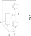
- Figure 2 shows an embodiment in which control system 40 is used to control an at least partially autonomous robot, e.g. an at least partially autonomous vehicle 100.
- Sensor 30 may comprise one or more video sensors and/or one or more radar sensors and/or one or more ultrasonic sensors and/or one or more LiDAR sensors and or one or more position sensors (like e.g. GPS). Some or all of these sensors are preferably but not necessarily integrated in vehicle 100.
- sensor 30 may comprise an information system for determining a state of the actuator system.
- One example for such an information system is a weather information system that determines a present or future state of the weather in environment 20.
- the classifier 60 may for example detect objects in the vicinity of the at least partially autonomous robot.
- Output signal y may comprise an information that characterizes where objects are located in the vicinity of the at least partially autonomous robot.
- Control command A may then be determined in accordance with this information, for example to avoid collisions with said detected objects.
- Actuator 10 which is preferably integrated in vehicle 100, may be given by a brake, a propulsion system, an engine, a drivetrain, or a steering of vehicle 100.
- Actuator control commands A may be determined such that actuator (or actuators) 10 is/are controlled such that vehicle 100 avoids collisions with said detected objects.
- Detected objects may also be classified according to what the classifier 60 deems them most likely to be, e.g. pedestrians or trees, and actuator control commands A may be determined depending on the classification.
- classifier 60 may be designed to identify lanes on a road ahead, e.g. by classifying a road surface and markings on said road, and identifying lanes as patches of road surface between said markings. Based on an output of a navigation system, a suitable target lane for pursuing a chosen path can then be selected, and depending on a present lane and said target lane, it may then be decided whether vehicle 10 is to switch lanes or stay in said present lane. Control command A may then be computed by e.g. retrieving a predefined motion pattern from a database corresponding to said identified action.
- corresponding constraints on possible motion patterns of vehicle 10 may then be retrieved from e.g. a database, a future path of vehicle 10 commensurate with said constraints may be computed, and said actuator control command A may be computed to steer the vehicle such as to execute said trajectory.
- a projected future behavior of said pedestrians and/or vehicles may be estimated, and based on said estimated future behavior, a trajectory may then be selected such as to avoid collision with said pedestrian and/or said vehicle, and said actuator control command A may be computed to steer the vehicle such as to execute said trajectory.
- the at least partially autonomous robot may be given by another mobile robot (not shown), which may, for example, move by flying, swimming, diving or stepping.
- the mobile robot may, inter alia, be an at least partially autonomous lawn mower, or an at least partially autonomous cleaning robot.
- actuator command control A may be determined such that propulsion unit and/or steering and/or brake of the mobile robot are controlled such that the mobile robot may avoid collisions with said identified objects.
- the at least partially autonomous robot may be given by a gardening robot (not shown), which uses sensor 30, preferably an optical sensor, to determine a state of plants in the environment 20.
- Actuator 10 may be a nozzle for spraying chemicals.
- an actuator control command A may be determined to cause actuator 10 to spray the plants with a suitable quantity of suitable chemicals.
- the at least partially autonomous robot may be given by a domestic appliance (not shown), like e.g. a washing machine, a stove, an oven, a microwave, or a dishwasher.
- Sensor 30, e.g. an optical sensor may detect a state of an object that is to undergo processing by the household appliance.
- sensor 30 may detect a state of the laundry inside the washing machine based on image.
- Actuator control signal A may then be determined depending on a detected material of the laundry.
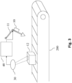
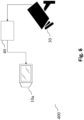
- control system 40 is used to control a manufacturing machine 11, e.g. a punch cutter, a cutter, a gun drill or a gripper) of a manufacturing system 200, e.g. as part of a production line.
- the control system 40 controls an actuator 10 which in turn control the manufacturing machine 11.
- Sensor 30 may be given by an optical sensor that captures properties of e.g. a manufactured product 12.
- Classifier 60 may determine a state of the manufactured product 12 from these captured properties, e.g. whether said product 12 is faulty or not.
- Actuator 10 which controls manufacturing machine 11 may then be controlled depending on the determined state of the manufactured product 12 for a subsequent manufacturing step of manufactured product 12.
- actuator 10 is controlled during manufacturing of a subsequent manufactured product 12 depending on the determined state of the manufactured product 12.
- actuator 10 may be controlled to select a product 12 that has been identified by classifier 60 as faulty and sort it into a designated bin, where they may be re-checked before discarding them.
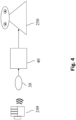
- control system 40 is used for controlling an automated personal assistant 250.
- Sensor 30 may be an optic sensor, e.g. for receiving video images of a gestures of user 249.
- sensor 30 may also be an audio sensor e.g. for receiving a voice command of user 249 as an audio signal.
- Control system 40 determines actuator control commands A for controlling the automated personal assistant 250.
- the actuator control commands A are determined in accordance with sensor signal S of sensor 30. Sensor signal S is transmitted to the control system 40.
- classifier 60 may be configured to e.g. carry out a gesture recognition algorithm to identify a gesture made by user 249.
- Control system 40 may then determine an actuator control command A for transmission to the automated personal assistant 250. It then transmits said actuator control command A to the automated personal assistant 250.
- actuator control command A may be determined in accordance with the identified user gesture recognized by classifier 60. It may then comprise information that causes the automated personal assistant 250 to retrieve information from a database and output this retrieved information in a form suitable for reception by user 249.
- control system 40 controls a domestic appliance (not shown) controlled in accordance with the identified user gesture.
- the domestic appliance may be a washing machine, a stove, an oven, a microwave or a dishwasher.
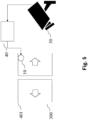
- Access control system may be designed to physically control access. It may, for example, comprise a door 401.
- Sensor 30 is configured to detect a scene that is relevant for deciding whether access is to be granted or not. It is an optical sensor for providing image or video data, for detecting a person's face.
- Classifier 60 may be configured to interpret this image or video data e.g. by matching identities with known people stored in a database, thereby determining an identity of the person.
- Actuator control signal A may then be determined depending on the interpretation of classifier 60, e.g. in accordance with the determined identity.
- Actuator 10 may be a lock that grants access or not depending on actuator control signal A.
- a non-physical, logical access control is also possible.
- control system 40 controls a surveillance system 400.
- Sensor 30 is configured to detect a scene that is under surveillance.
- the control system does not necessarily control an actuator 10, but a display 10a.
- the machine learning system 60 may determine a classification of a scene, e.g. whether the scene detected by optical sensor 30 is suspicious.
- Actuator control signal A which is transmitted to display 10a may then e.g. be configured to cause display 10a to adjust the displayed content dependent on the determined classification, e.g. to highlight an object that is deemed suspicious by machine learning system 60.
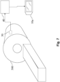
- Shown in figure 7 is an embodiment of a control system 40 for controlling an imaging system 500, for example an MRI apparatus, x-ray imaging apparatus or ultrasonic imaging apparatus.
- Sensor 30 may, for example, be an imaging sensor.
- Machine learning system 60 may then determine a classification of all or part of the sensed image. Actuator control signal A may then be chosen in accordance with this classification, thereby controlling display 10a.
- machine-learning system 60 may interpret a region of the sensed image to be potentially anomalous. In this case, actuator control signal A may be determined to cause display 10a to display the imaging and highlighting the potentially anomalous region.
- a training data unit 150 determines input signals x, which are passed on to classifier 60.
- training data unit 150 may access a computer-implemented database St 2 in which at least one set T of training data is stored.
- the at least one set T comprises pairs of input signals x i and corresponding desired output signals y i . Desired output signal y i is passed on to assessment unit 180.
- the set T of training data may be a full set of training data. It may also be a selected batch of training data if training is performed in batches.
- Classifier 60 is configured to compute output signals ⁇ from input signal x i . These output signals ⁇ i are also passed on to assessment unit 180.
- a modification unit 160 determines updated parameters ⁇ ' depending on input from assessment unit 180. Updated parameters ⁇ 'are transmitted to parameter storage St 1 to replace present parameters ⁇ .
- training system 140 may comprise a processor 145 (or a plurality of processors) and at least one machine-readable storage medium 146 on which instructions are stored which, if carried out, cause control system 140 to carry out a method according to one aspect of the invention.
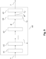
- FIG 9 Shown in figure 9 is an exemplary structure of classifier 60, which in this embodiment is given by a neural network that is parametrized by parameters, or weights, ⁇ .
- Input data is x is fed into input layer 61, processed and then successively passed on to hidden layers 62 and 63.
- the output of layer 63 is a feature map ⁇ .
- layers 61, 62 and 63 comprise at least one convolutional layer. Parameters that parametrize layers 61, 62 and 63 are called w.
- Feature map ⁇ is passed on to a fully-connected layer 64, which is parametrized by parameters ⁇ f .
- the output ⁇ T is shown in figure 9 exemplary structure of classifier 60, which in this embodiment is given by a neural network that is parametrized by parameters, or weights, ⁇ .
- Input data is x is fed into input layer 61, processed and then successively passed on to hidden layers 62 and 63.
- the output of layer 63 is
- ⁇ f is passed on to a final layer 65 that comprises computing a softmax transformation for output ⁇ T ⁇ ⁇ f and an argmax function that selects the label y of the classification that corresponds to the highest softmax score as the output signal of classifier 60.
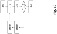
- Shown in figure 10 is a flow-chart diagram that outlines an embodiment of the training method for training classifier 60 that may be carried out by training system 140.
- Lagrangian multiplier values ⁇ are initialized, e.g. randomly or as a predefined value, e.g. 0.
- Parameters ⁇ f of fully-connected layer 64 are set equal to Lagrangian multiplier values ⁇ .
- Dataset T is provided, as well as parameters a i , b i , f i , g i that characterize the metric as defined in equation (M).
- parameters characterizing a constraint as given in equation (7) are also provided.
- step (1040) the increment to d ⁇ are taken as an increment to parameters ⁇ f of fully-connected layer 64 and backpropagated through the remaining network, i.e. through layers 63, 62 and 61 to obtain an increment dw to parameters w and the method continues with step (1050).
- parameters w can remain fixed and the method branches directly from step (1030) to step (1050).
- step (1050) parameters ⁇ , ⁇ f , and w are updated as ⁇ ⁇ ⁇ + d ⁇ w ⁇ w + dw ⁇ f ⁇ ⁇ .
- step (1010) the method continues with step (1010) and iterates until the method is concluded in step (1060).
- Shown in figure 11 is a flow-chart diagram of the method to compute the optimum value Q * of the inner minimax problem as stated in equation (5) (or (7)) in step (1010).
- D kl ⁇ j a j g j k l
- E kl ⁇ j b j g j k l
- F kl ⁇ j f j g j k l .
- Z(Q) is increased by an a n ⁇ n -dimensional matrix E that is 0 everywhere, except at position (n,n) where it is set to Q nn .
- Q * is computed as the optimum value of the linear program min Q ; ⁇ ; v v + c Q ⁇ Q W s.t.: q i , k ⁇ 0 ⁇ i , k ⁇ 1 n ⁇ i , k ⁇ 0 ⁇ i , k ⁇ 1 n v ⁇ 0 q i , k ⁇ 1 k ⁇ j q j , k ⁇ i , k ⁇ 1 n ⁇ k 1 k ⁇ i q i , k ⁇ 1 ⁇ Z ′ Q i k ⁇ ⁇ i , k + 1 k ⁇ j ⁇ j , k , ⁇ i , k ⁇ 1 n ,
- Q * is obtained as the optimum value by solving the linear program min Q ; ⁇ ; ⁇ ; v v + c Q ⁇ Q W + ⁇ l ⁇ l ⁇ ⁇ l s.t.: q i , k ⁇ 0 ⁇ i , k ⁇ 1 n ⁇ i , k ⁇ 0 ⁇ i , k ⁇ 1 n ⁇ l ⁇ 0 ⁇ l ⁇ 1 v ⁇ 0 q i , k ⁇ 1 k ⁇ j q j , k ⁇ i , k ⁇ 1 n ⁇ k 1 k ⁇ i q i , k ⁇ 1 v ⁇ Z ′ Q i k ⁇ ⁇ i , k + 1 k ⁇ j ⁇ j , k + ⁇ l i k , ⁇
- the term "computer” covers any device for the processing of pre-defined calculation instructions. These calculation instructions can be in the form of software, or in the form of hardware, or also in a mixed form of software and hardware.
Landscapes
- Engineering & Computer Science (AREA)
- Theoretical Computer Science (AREA)
- Physics & Mathematics (AREA)
- General Physics & Mathematics (AREA)
- Data Mining & Analysis (AREA)
- General Engineering & Computer Science (AREA)
- Artificial Intelligence (AREA)
- Evolutionary Computation (AREA)
- Life Sciences & Earth Sciences (AREA)
- Software Systems (AREA)
- Mathematical Physics (AREA)
- Computing Systems (AREA)
- Computational Linguistics (AREA)
- General Health & Medical Sciences (AREA)
- Health & Medical Sciences (AREA)
- Biophysics (AREA)
- Molecular Biology (AREA)
- Biomedical Technology (AREA)
- Computer Vision & Pattern Recognition (AREA)
- Evolutionary Biology (AREA)
- Bioinformatics & Cheminformatics (AREA)
- Bioinformatics & Computational Biology (AREA)
- Manufacturing & Machinery (AREA)
- Multimedia (AREA)
- Automation & Control Theory (AREA)
- Human Computer Interaction (AREA)
- Business, Economics & Management (AREA)
- Image Analysis (AREA)
- Human Resources & Organizations (AREA)
- Strategic Management (AREA)
- Economics (AREA)
- General Business, Economics & Management (AREA)
- Tourism & Hospitality (AREA)
- Medical Informatics (AREA)
- Development Economics (AREA)
- Educational Administration (AREA)
- Entrepreneurship & Innovation (AREA)
- Marketing (AREA)
- Management, Administration, Business Operations System, And Electronic Commerce (AREA)
- Primary Health Care (AREA)
Claims (11)
- Computerimplementiertes Verfahren zum Verwenden eines Bildklassifikators (60) insbesondere eines binären Klassifikators zum Klassifizieren von Sensorsignalen eines optischen Sensors, um ein Stellgliedsteuersignal (A) zum Steuern eines Stellglieds (10) bereitzustellen,wobei das Stellglied (10) einen mindestens teilweise autonomen Roboter (100) und/oder eine Fertigungsmaschine (200) und/oder ein Zugriffssteuersystem (300) steuert,wobei der Klassifikator (60) trainiert wird zum Klassifizieren von Eingangssignalen (x i ), um eine Leistungsfähigkeit gemäß einer unzerlegbaren Metrik zu optimieren, die eine Angleichung zwischen Klassifizierungen (yi ), die den Eingangssignalen (xi ) eines Satzes von Trainingsdaten entsprechen, und entsprechenden vorhergesagten Klassifizierungen (ŷi ) der Eingangssignale misst, die von dem Klassifikator erhalten werden, wobei das Training die folgenden Schritte umfasst:- Bereitstellen von Gewichtungsfaktoren (aj , bj, fj, gj ), die charakterisieren, wie die unzerlegbare Metrik von einer Vielzahl von Termen (RP, TN, PP, AP, AN) aus einer Konfusionsmatrix der Klassifizierungen (yi ) und den vorhergesagten Klassifizierungen (ŷi ) abhängig ist;- Trainieren des Klassifikators (60) in Abhängigkeit von den bereitgestellten Gewichtungsfaktoren (aj , bj, fj, gj ),wobei die Optimierung als ein kontradiktorisches Vorhersageverfahren aufgeführt wird,wobei das Verfahren zum Verwenden des Bildklassifikators die folgenden Schritte umfasst:- Empfangen eines Sensorsignals (S), das Daten von einem optischen Sensor (30) umfasst,- Ermitteln eines Eingangssignals (x), das von dem Sensorsignal (S) abhängig ist,
und- Einspeisen des Eingangssignals (x) in den Klassifikator (60), um ein Ausgangssignal (y) zu erhalten, dass eine Klassifizierung des Eingangssignals (x) charakterisiert,- Ermitteln des Stellgliedsteuersignals (A) in Abhängigkeit von dem Ausgangssignal (y). - Verfahren nach Anspruch 1, bei dem die unzerlegbare Metrik gegeben ist durch die Formel

- Verfahren nach Anspruch 2, bei dem die Optimierung ausgeführt wird, indem ein Gleichgewicht in einem Spiel für zwei Akteure zwischen einem ersten Akteur (P) und einen zweiten Akteur(Q) gesucht wird, wobei der erste Akteur (P) versucht erste Klassifizierungen (ŷi ) zu finden, die den Eingangssignalen (xi ) der Trainingsdaten (T) entsprechen, und der zweite Akteur (Q) versucht zweite Klassifizierungen (yi) zu finden, die den Eingangssignalen (xi ) der Trainingsdaten (T) entsprechen, und wobei der erste Akteur (P) versucht einen Erwartungswert der Metrik zu maximieren und der zweite Akteur (Q) versucht den Erwartungswert der Metrik zu minimieren, durch den die Konfusionsmatrix basierend auf den ersten Klassifizierungen (ŷi ) und den zweiten Klassifizierungen (


- Verfahren nach Anspruch 3, bei dem die Optimierung ausgeführt wird, indem ein optimaler Wert eines Lagrange-Multiplikators (θ) gesucht wird, welcher der Momentabgleichsbedingung entspricht und wobei trainierte Parameter einer dicht vernetzten Schicht (64) des binären Klassifikators (60) gleich dem optimalen Wert des Lagrange-Multiplikators (θ) eingestellt werden.
- Verfahren nach Anspruch 4, wobei der Erwartungswert basierend auf Randwahr-scheinlichkeiten (

- Verfahren nach Anspruch 5, bei dem die Optimierung ein Lösen des Spiels für zwei Akteure umfasst, indem ein lineares Programm in nur einem dieser beiden Akteure (P, Q) gelöst wird.
- Verfahren nach einem der vorhergehenden Ansprüche, wobei die Optimierung der Leistungsfähigkeit gemäß der unzerlegbaren Metrik ferner einer Ungleichheitsbedingung eines erwarteten Werts einer zweiten Metrik unterzogen wird, die eine Angleichung zwischen den Klassifizierungen (yi ) und den vorhergesagten Klassifizierungen (ŷi ) misst.
- Computerprogramm, das konfiguriert ist, um einen Computer zu veranlassen, das Verfahren nach einem der Ansprüche 1 bis 7 mit all seinen Schritten auszuführen, wenn das Computerprogramm durch einen Prozessor (45, 145) ausgeführt wird.
- Maschinenlesbares Speichermedium (46, 146), in dem das Computerprogramm nach Anspruch 8 gespeichert ist.
- Steuersystem (40) zum Betreiben eines Stellglieds (10), wobei das Steuersystem (40) den Klassifikator (60) umfasst, der mit dem Verfahren nach einem der Ansprüche 1 bis 7 trainiert wurde und konfiguriert ist, um das Stellglied (10) gemäß einer Ausgabe des Klassifikators (60) zu betreiben.
- System (40), das konfiguriert ist zum Ausführen des Verfahrens nach einem der Ansprüche 1 bis 7.
Priority Applications (5)
| Application Number | Priority Date | Filing Date | Title |
|---|---|---|---|
| EP19212867.6A EP3832550B1 (de) | 2019-12-02 | 2019-12-02 | Vorrichtung und verfahren zum trainieren eines klassifikators |
| US16/950,396 US11960991B2 (en) | 2019-12-02 | 2020-11-17 | Device and method for training a classifier |
| KR1020200161963A KR20210068993A (ko) | 2019-12-02 | 2020-11-27 | 분류기를 훈련하는 디바이스 및 방법 |
| CN202011379943.1A CN112990248A (zh) | 2019-12-02 | 2020-12-01 | 用于训练分类器的装置和方法 |
| JP2020199674A JP7828522B2 (ja) | 2019-12-02 | 2020-12-01 | クラス分類器を訓練するための装置および方法 |
Applications Claiming Priority (1)
| Application Number | Priority Date | Filing Date | Title |
|---|---|---|---|
| EP19212867.6A EP3832550B1 (de) | 2019-12-02 | 2019-12-02 | Vorrichtung und verfahren zum trainieren eines klassifikators |
Publications (2)
| Publication Number | Publication Date |
|---|---|
| EP3832550A1 EP3832550A1 (de) | 2021-06-09 |
| EP3832550B1 true EP3832550B1 (de) | 2025-02-12 |
Family
ID=68762600
Family Applications (1)
| Application Number | Title | Priority Date | Filing Date |
|---|---|---|---|
| EP19212867.6A Active EP3832550B1 (de) | 2019-12-02 | 2019-12-02 | Vorrichtung und verfahren zum trainieren eines klassifikators |
Country Status (5)
| Country | Link |
|---|---|
| US (1) | US11960991B2 (de) |
| EP (1) | EP3832550B1 (de) |
| JP (1) | JP7828522B2 (de) |
| KR (1) | KR20210068993A (de) |
| CN (1) | CN112990248A (de) |
Families Citing this family (4)
| Publication number | Priority date | Publication date | Assignee | Title |
|---|---|---|---|---|
| EP4105847A1 (de) * | 2021-06-16 | 2022-12-21 | Robert Bosch GmbH | Vorrichtung und verfahren zur anpassung eines vortrainierten maschinenlernsystems an zieldaten, die eine unterschiedliche verteilung als die trainingsdaten aufweisen, ohne die notwendigkeit menschlicher annotationen an den zieldaten |
| CN115857359B (zh) * | 2022-12-27 | 2023-07-28 | 广东非凡实业有限公司 | 高强度泥土的制备工艺及其系统 |
| CN117197029B (zh) * | 2023-04-28 | 2024-05-03 | 浙江工交机械股份有限公司 | 球销的自动化生产线及其方法 |
| CN116824517B (zh) * | 2023-08-31 | 2023-11-17 | 安徽博诺思信息科技有限公司 | 基于可视化的变电站运维安全管控系统 |
Family Cites Families (5)
| Publication number | Priority date | Publication date | Assignee | Title |
|---|---|---|---|---|
| US9256944B2 (en) * | 2014-05-19 | 2016-02-09 | Rockwell Automation Technologies, Inc. | Integration of optical area monitoring with industrial machine control |
| EP3423989B1 (de) * | 2016-03-03 | 2020-02-19 | Telefonaktiebolaget LM Ericsson (PUBL) | Unsicherheitsmesswert eines muster klassifizierers nach einem vermischungsmodell |
| US9751212B1 (en) | 2016-05-05 | 2017-09-05 | Toyota Jidosha Kabushiki Kaisha | Adapting object handover from robot to human using perceptual affordances |
| US11475351B2 (en) * | 2017-11-15 | 2022-10-18 | Uatc, Llc | Systems and methods for object detection, tracking, and motion prediction |
| DE202019105282U1 (de) * | 2019-09-24 | 2019-11-15 | Albert-Ludwigs-Universität Freiburg | Vorrichtung zum Optimieren eines System für das maschinelle Lernen |
-
2019
- 2019-12-02 EP EP19212867.6A patent/EP3832550B1/de active Active
-
2020
- 2020-11-17 US US16/950,396 patent/US11960991B2/en active Active
- 2020-11-27 KR KR1020200161963A patent/KR20210068993A/ko active Pending
- 2020-12-01 JP JP2020199674A patent/JP7828522B2/ja active Active
- 2020-12-01 CN CN202011379943.1A patent/CN112990248A/zh active Pending
Also Published As
| Publication number | Publication date |
|---|---|
| US20210165391A1 (en) | 2021-06-03 |
| KR20210068993A (ko) | 2021-06-10 |
| JP7828522B2 (ja) | 2026-03-12 |
| CN112990248A (zh) | 2021-06-18 |
| JP2021089731A (ja) | 2021-06-10 |
| US11960991B2 (en) | 2024-04-16 |
| EP3832550A1 (de) | 2021-06-09 |
Similar Documents
| Publication | Publication Date | Title |
|---|---|---|
| US11676025B2 (en) | Method, apparatus and computer program for generating robust automatic learning systems and testing trained automatic learning systems | |
| US12243283B2 (en) | Device and method for determining a semantic segmentation and/or an instance segmentation of an image | |
| US11960991B2 (en) | Device and method for training a classifier | |
| US20230004826A1 (en) | Device and method for classifying a signal and/or for performing regression analysis on a signal | |
| US20210264261A1 (en) | Systems and methods for few shot object detection | |
| US12050990B2 (en) | Device and method for training an augmented discriminator | |
| US12536339B2 (en) | Device and method for determining adversarial patches for a machine learning system | |
| US20220391704A1 (en) | Method and system for scene graph generation | |
| US12159447B2 (en) | Device and method for training a classifier | |
| US20220076096A1 (en) | Device and method for training a scale-equivariant convolutional neural network | |
| EP4105839A1 (de) | Vorrichtung und verfahren zur anpassung eines vortrainierten maschinenlernsystems an zieldaten, die eine unterschiedliche verteilung als die trainingsdaten aufweisen, ohne die notwendigkeit menschlicher annotationen an den zieldaten | |
| US8213709B1 (en) | Method and system for directed area search using cognitive swarm vision and cognitive Bayesian reasoning | |
| US20220101129A1 (en) | Device and method for classifying an input signal using an invertible factorization model | |
| US20230418246A1 (en) | Device and method for determining adversarial perturbations of a machine learning system | |
| US20210319267A1 (en) | Device and method for training a classifier | |
| EP3671574B1 (de) | Vorrichtung und verfahren zur verbesserung der robustheit gegenüber kontradiktorischen beispielen | |
| US20230072747A1 (en) | Device and method for training a neural network for image analysis | |
| US12468937B2 (en) | Device and method for training a classifier using an invertible factorization model | |
| EP4105847A1 (de) | Vorrichtung und verfahren zur anpassung eines vortrainierten maschinenlernsystems an zieldaten, die eine unterschiedliche verteilung als die trainingsdaten aufweisen, ohne die notwendigkeit menschlicher annotationen an den zieldaten | |
| US20210319268A1 (en) | Device and method to improve the robustness against 'adversarial examples' | |
| EP4343619A1 (de) | Verfahren zur regulierung eines neuronalen netzes | |
| EP4550216A1 (de) | Vorrichtung und verfahren zum trainieren eines neuronalen netzes für multitask-lernen | |
| US20230368007A1 (en) | Neural network layer for non-linear normalization | |
| US20250218163A1 (en) | Out-of-distribution detection with projection of gradients | |
| Park | Insight into ML Security: Adversarial Attacks and Defences in Black-box Settings |
Legal Events
| Date | Code | Title | Description |
|---|---|---|---|
| PUAI | Public reference made under article 153(3) epc to a published international application that has entered the european phase |
Free format text: ORIGINAL CODE: 0009012 |
|
| STAA | Information on the status of an ep patent application or granted ep patent |
Free format text: STATUS: THE APPLICATION HAS BEEN PUBLISHED |
|
| AK | Designated contracting states |
Kind code of ref document: A1 Designated state(s): AL AT BE BG CH CY CZ DE DK EE ES FI FR GB GR HR HU IE IS IT LI LT LU LV MC MK MT NL NO PL PT RO RS SE SI SK SM TR |
|
| STAA | Information on the status of an ep patent application or granted ep patent |
Free format text: STATUS: REQUEST FOR EXAMINATION WAS MADE |
|
| 17P | Request for examination filed |
Effective date: 20211209 |
|
| RBV | Designated contracting states (corrected) |
Designated state(s): AL AT BE BG CH CY CZ DE DK EE ES FI FR GB GR HR HU IE IS IT LI LT LU LV MC MK MT NL NO PL PT RO RS SE SI SK SM TR |
|
| STAA | Information on the status of an ep patent application or granted ep patent |
Free format text: STATUS: EXAMINATION IS IN PROGRESS |
|
| 17Q | First examination report despatched |
Effective date: 20230504 |
|
| GRAP | Despatch of communication of intention to grant a patent |
Free format text: ORIGINAL CODE: EPIDOSNIGR1 |
|
| STAA | Information on the status of an ep patent application or granted ep patent |
Free format text: STATUS: GRANT OF PATENT IS INTENDED |
|
| INTG | Intention to grant announced |
Effective date: 20240905 |
|
| GRAS | Grant fee paid |
Free format text: ORIGINAL CODE: EPIDOSNIGR3 |
|
| GRAA | (expected) grant |
Free format text: ORIGINAL CODE: 0009210 |
|
| STAA | Information on the status of an ep patent application or granted ep patent |
Free format text: STATUS: THE PATENT HAS BEEN GRANTED |
|
| AK | Designated contracting states |
Kind code of ref document: B1 Designated state(s): AL AT BE BG CH CY CZ DE DK EE ES FI FR GB GR HR HU IE IS IT LI LT LU LV MC MK MT NL NO PL PT RO RS SE SI SK SM TR |
|
| REG | Reference to a national code |
Ref country code: GB Ref legal event code: FG4D |
|
| REG | Reference to a national code |
Ref country code: CH Ref legal event code: EP |
|
| REG | Reference to a national code |
Ref country code: DE Ref legal event code: R096 Ref document number: 602019065713 Country of ref document: DE |
|
| REG | Reference to a national code |
Ref country code: IE Ref legal event code: FG4D |
|
| U01 | Request for unitary effect filed |
Effective date: 20250313 |
|
| REG | Reference to a national code |
Ref country code: NL Ref legal event code: MP Effective date: 20250212 |
|
| U04 | Request for unitary effect rejected |
Effective date: 20250523 |
|
| PG25 | Lapsed in a contracting state [announced via postgrant information from national office to epo] |
Ref country code: RS Free format text: LAPSE BECAUSE OF FAILURE TO SUBMIT A TRANSLATION OF THE DESCRIPTION OR TO PAY THE FEE WITHIN THE PRESCRIBED TIME-LIMIT Effective date: 20250512 |
|
| PG25 | Lapsed in a contracting state [announced via postgrant information from national office to epo] |
Ref country code: FI Free format text: LAPSE BECAUSE OF FAILURE TO SUBMIT A TRANSLATION OF THE DESCRIPTION OR TO PAY THE FEE WITHIN THE PRESCRIBED TIME-LIMIT Effective date: 20250212 |
|
| PG25 | Lapsed in a contracting state [announced via postgrant information from national office to epo] |
Ref country code: PL Free format text: LAPSE BECAUSE OF FAILURE TO SUBMIT A TRANSLATION OF THE DESCRIPTION OR TO PAY THE FEE WITHIN THE PRESCRIBED TIME-LIMIT Effective date: 20250212 |
|
| PG25 | Lapsed in a contracting state [announced via postgrant information from national office to epo] |
Ref country code: ES Free format text: LAPSE BECAUSE OF FAILURE TO SUBMIT A TRANSLATION OF THE DESCRIPTION OR TO PAY THE FEE WITHIN THE PRESCRIBED TIME-LIMIT Effective date: 20250212 |
|
| REG | Reference to a national code |
Ref country code: LT Ref legal event code: MG9D |
|
| PG25 | Lapsed in a contracting state [announced via postgrant information from national office to epo] |
Ref country code: IS Free format text: LAPSE BECAUSE OF FAILURE TO SUBMIT A TRANSLATION OF THE DESCRIPTION OR TO PAY THE FEE WITHIN THE PRESCRIBED TIME-LIMIT Effective date: 20250612 Ref country code: NO Free format text: LAPSE BECAUSE OF FAILURE TO SUBMIT A TRANSLATION OF THE DESCRIPTION OR TO PAY THE FEE WITHIN THE PRESCRIBED TIME-LIMIT Effective date: 20250512 |
|
| PG25 | Lapsed in a contracting state [announced via postgrant information from national office to epo] |
Ref country code: NL Free format text: LAPSE BECAUSE OF FAILURE TO SUBMIT A TRANSLATION OF THE DESCRIPTION OR TO PAY THE FEE WITHIN THE PRESCRIBED TIME-LIMIT Effective date: 20250212 |
|
| PG25 | Lapsed in a contracting state [announced via postgrant information from national office to epo] |
Ref country code: HR Free format text: LAPSE BECAUSE OF FAILURE TO SUBMIT A TRANSLATION OF THE DESCRIPTION OR TO PAY THE FEE WITHIN THE PRESCRIBED TIME-LIMIT Effective date: 20250212 |
|
| PG25 | Lapsed in a contracting state [announced via postgrant information from national office to epo] |
Ref country code: PT Free format text: LAPSE BECAUSE OF FAILURE TO SUBMIT A TRANSLATION OF THE DESCRIPTION OR TO PAY THE FEE WITHIN THE PRESCRIBED TIME-LIMIT Effective date: 20250612 |
|
| PG25 | Lapsed in a contracting state [announced via postgrant information from national office to epo] |
Ref country code: BG Free format text: LAPSE BECAUSE OF FAILURE TO SUBMIT A TRANSLATION OF THE DESCRIPTION OR TO PAY THE FEE WITHIN THE PRESCRIBED TIME-LIMIT Effective date: 20250212 Ref country code: GR Free format text: LAPSE BECAUSE OF FAILURE TO SUBMIT A TRANSLATION OF THE DESCRIPTION OR TO PAY THE FEE WITHIN THE PRESCRIBED TIME-LIMIT Effective date: 20250513 |
|
| PG25 | Lapsed in a contracting state [announced via postgrant information from national office to epo] |
Ref country code: SE Free format text: LAPSE BECAUSE OF FAILURE TO SUBMIT A TRANSLATION OF THE DESCRIPTION OR TO PAY THE FEE WITHIN THE PRESCRIBED TIME-LIMIT Effective date: 20250212 |
|
| PG25 | Lapsed in a contracting state [announced via postgrant information from national office to epo] |
Ref country code: SM Free format text: LAPSE BECAUSE OF FAILURE TO SUBMIT A TRANSLATION OF THE DESCRIPTION OR TO PAY THE FEE WITHIN THE PRESCRIBED TIME-LIMIT Effective date: 20250212 |
|
| PG25 | Lapsed in a contracting state [announced via postgrant information from national office to epo] |
Ref country code: IT Free format text: LAPSE BECAUSE OF FAILURE TO SUBMIT A TRANSLATION OF THE DESCRIPTION OR TO PAY THE FEE WITHIN THE PRESCRIBED TIME-LIMIT Effective date: 20250212 |
|
| PG25 | Lapsed in a contracting state [announced via postgrant information from national office to epo] |
Ref country code: CZ Free format text: LAPSE BECAUSE OF FAILURE TO SUBMIT A TRANSLATION OF THE DESCRIPTION OR TO PAY THE FEE WITHIN THE PRESCRIBED TIME-LIMIT Effective date: 20250212 Ref country code: EE Free format text: LAPSE BECAUSE OF FAILURE TO SUBMIT A TRANSLATION OF THE DESCRIPTION OR TO PAY THE FEE WITHIN THE PRESCRIBED TIME-LIMIT Effective date: 20250212 |
|
| PG25 | Lapsed in a contracting state [announced via postgrant information from national office to epo] |
Ref country code: RO Free format text: LAPSE BECAUSE OF FAILURE TO SUBMIT A TRANSLATION OF THE DESCRIPTION OR TO PAY THE FEE WITHIN THE PRESCRIBED TIME-LIMIT Effective date: 20250212 |
|
| PG25 | Lapsed in a contracting state [announced via postgrant information from national office to epo] |
Ref country code: SK Free format text: LAPSE BECAUSE OF FAILURE TO SUBMIT A TRANSLATION OF THE DESCRIPTION OR TO PAY THE FEE WITHIN THE PRESCRIBED TIME-LIMIT Effective date: 20250212 |
|
| REG | Reference to a national code |
Ref country code: DE Ref legal event code: R097 Ref document number: 602019065713 Country of ref document: DE |
|
| PLBE | No opposition filed within time limit |
Free format text: ORIGINAL CODE: 0009261 |
|
| STAA | Information on the status of an ep patent application or granted ep patent |
Free format text: STATUS: NO OPPOSITION FILED WITHIN TIME LIMIT |
|
| PGFP | Annual fee paid to national office [announced via postgrant information from national office to epo] |
Ref country code: GB Payment date: 20251218 Year of fee payment: 7 |
|
| PGFP | Annual fee paid to national office [announced via postgrant information from national office to epo] |
Ref country code: FR Payment date: 20251218 Year of fee payment: 7 |
|
| 26N | No opposition filed |
Effective date: 20251113 |
|
| PGFP | Annual fee paid to national office [announced via postgrant information from national office to epo] |
Ref country code: DE Payment date: 20260223 Year of fee payment: 7 |