EP3832391A1 - Clamp assembly - Google Patents
Clamp assembly Download PDFInfo
- Publication number
- EP3832391A1 EP3832391A1 EP19213292.6A EP19213292A EP3832391A1 EP 3832391 A1 EP3832391 A1 EP 3832391A1 EP 19213292 A EP19213292 A EP 19213292A EP 3832391 A1 EP3832391 A1 EP 3832391A1
- Authority
- EP
- European Patent Office
- Prior art keywords
- clamp
- gas
- base surface
- lower base
- liquid
- Prior art date
- Legal status (The legal status is an assumption and is not a legal conclusion. Google has not performed a legal analysis and makes no representation as to the accuracy of the status listed.)
- Withdrawn
Links
Images




Classifications
-
- G—PHYSICS
- G03—PHOTOGRAPHY; CINEMATOGRAPHY; ANALOGOUS TECHNIQUES USING WAVES OTHER THAN OPTICAL WAVES; ELECTROGRAPHY; HOLOGRAPHY
- G03F—PHOTOMECHANICAL PRODUCTION OF TEXTURED OR PATTERNED SURFACES, e.g. FOR PRINTING, FOR PROCESSING OF SEMICONDUCTOR DEVICES; MATERIALS THEREFOR; ORIGINALS THEREFOR; APPARATUS SPECIALLY ADAPTED THEREFOR
- G03F7/00—Photomechanical, e.g. photolithographic, production of textured or patterned surfaces, e.g. printing surfaces; Materials therefor, e.g. comprising photoresists; Apparatus specially adapted therefor
- G03F7/70—Microphotolithographic exposure; Apparatus therefor
- G03F7/70691—Handling of masks or workpieces
- G03F7/707—Chucks, e.g. chucking or un-chucking operations or structural details
- G03F7/70708—Chucks, e.g. chucking or un-chucking operations or structural details being electrostatic; Electrostatically deformable vacuum chucks
-
- G—PHYSICS
- G03—PHOTOGRAPHY; CINEMATOGRAPHY; ANALOGOUS TECHNIQUES USING WAVES OTHER THAN OPTICAL WAVES; ELECTROGRAPHY; HOLOGRAPHY
- G03F—PHOTOMECHANICAL PRODUCTION OF TEXTURED OR PATTERNED SURFACES, e.g. FOR PRINTING, FOR PROCESSING OF SEMICONDUCTOR DEVICES; MATERIALS THEREFOR; ORIGINALS THEREFOR; APPARATUS SPECIALLY ADAPTED THEREFOR
- G03F7/00—Photomechanical, e.g. photolithographic, production of textured or patterned surfaces, e.g. printing surfaces; Materials therefor, e.g. comprising photoresists; Apparatus specially adapted therefor
- G03F7/70—Microphotolithographic exposure; Apparatus therefor
- G03F7/70691—Handling of masks or workpieces
- G03F7/707—Chucks, e.g. chucking or un-chucking operations or structural details
-
- G—PHYSICS
- G03—PHOTOGRAPHY; CINEMATOGRAPHY; ANALOGOUS TECHNIQUES USING WAVES OTHER THAN OPTICAL WAVES; ELECTROGRAPHY; HOLOGRAPHY
- G03F—PHOTOMECHANICAL PRODUCTION OF TEXTURED OR PATTERNED SURFACES, e.g. FOR PRINTING, FOR PROCESSING OF SEMICONDUCTOR DEVICES; MATERIALS THEREFOR; ORIGINALS THEREFOR; APPARATUS SPECIALLY ADAPTED THEREFOR
- G03F7/00—Photomechanical, e.g. photolithographic, production of textured or patterned surfaces, e.g. printing surfaces; Materials therefor, e.g. comprising photoresists; Apparatus specially adapted therefor
- G03F7/70—Microphotolithographic exposure; Apparatus therefor
- G03F7/708—Construction of apparatus, e.g. environment aspects, hygiene aspects or materials
- G03F7/70858—Environment aspects, e.g. pressure of beam-path gas, temperature
-
- G—PHYSICS
- G03—PHOTOGRAPHY; CINEMATOGRAPHY; ANALOGOUS TECHNIQUES USING WAVES OTHER THAN OPTICAL WAVES; ELECTROGRAPHY; HOLOGRAPHY
- G03F—PHOTOMECHANICAL PRODUCTION OF TEXTURED OR PATTERNED SURFACES, e.g. FOR PRINTING, FOR PROCESSING OF SEMICONDUCTOR DEVICES; MATERIALS THEREFOR; ORIGINALS THEREFOR; APPARATUS SPECIALLY ADAPTED THEREFOR
- G03F7/00—Photomechanical, e.g. photolithographic, production of textured or patterned surfaces, e.g. printing surfaces; Materials therefor, e.g. comprising photoresists; Apparatus specially adapted therefor
- G03F7/70—Microphotolithographic exposure; Apparatus therefor
- G03F7/708—Construction of apparatus, e.g. environment aspects, hygiene aspects or materials
- G03F7/70908—Hygiene, e.g. preventing apparatus pollution, mitigating effect of pollution or removing pollutants from apparatus
- G03F7/70941—Stray fields and charges, e.g. stray light, scattered light, flare, transmission loss
-
- H—ELECTRICITY
- H10—SEMICONDUCTOR DEVICES; ELECTRIC SOLID-STATE DEVICES NOT OTHERWISE PROVIDED FOR
- H10P—GENERIC PROCESSES OR APPARATUS FOR THE MANUFACTURE OR TREATMENT OF DEVICES COVERED BY CLASS H10
- H10P72/00—Handling or holding of wafers, substrates or devices during manufacture or treatment thereof
- H10P72/70—Handling or holding of wafers, substrates or devices during manufacture or treatment thereof for supporting or gripping
- H10P72/72—Handling or holding of wafers, substrates or devices during manufacture or treatment thereof for supporting or gripping using electrostatic chucks
Definitions
- the present invention relates to a clamp assembly and an associated method of use of the clamp assembly.
- the clamp assembly may find utility in a lithographic apparatus.
- a lithographic apparatus is a machine constructed to apply a desired pattern onto a substrate.
- a lithographic apparatus can be used, for example, in the manufacture of integrated circuits (ICs).
- a lithographic apparatus may, for example, project a pattern (also often referred to as "design layout" or "design") of a patterning device (e.g., a mask) onto a layer of radiation-sensitive material (resist) provided on a substrate (e.g., a wafer).
- lithographic apparatus may use electromagnetic radiation.
- the wavelength of this radiation determines the minimum size of features which are patterned on the substrate. Typical wavelengths currently in use are 365 nm (i-line), 248 nm, 193 nm and 13.5 nm.
- a lithographic apparatus which uses extreme ultraviolet (EUV) radiation, having a wavelength within a range of 4 nm to 20 nm, for example 6.7 nm or 13.5 nm, may be used to form smaller features on a substrate than a lithographic apparatus which uses, for example, radiation with a wavelength of 193 nm.
- EUV extreme ultraviolet
- Such lithographic apparatuses may be provided with one or more clamps to clamp the patterning device and/or substrate to an object support, such as a mask table or a wafer table respectively.
- the clamp may be, for example, a mechanical clamp, a vacuum clamp, or an electrostatic clamp. Electrostatic clamps may be particularly suited to operating at EUV wavelengths, since regions of an EUV lithographic apparatus necessarily operate under near vacuum conditions.
- Electrostatic clamps are often maintained in a low-pressure hydrogen-rich environment, which is a generally non-conductive environment. As such, electric charge may accumulate on dielectric or ungrounded surfaces of the clamp. The accumulated charge may be non-uniformly distributed across the surfaces. Such non-uniformly distributed accumulated charge may have detrimental effects on the general operation of the lithographic apparatus. For example, a non-uniformly distributed charge on a charged surface of a clamp may result in unwanted deformation of components of the lithographic apparatus in relatively close proximity to the clamp, potentially affecting precise positioning of the patterning device and/or substrate within the lithographic apparatus.
- a clamp assembly comprising a clamp configurable to clamp a support member to a lower base surface of the clamp by electrostatic adhesion, and an arrangement configurable to direct a gas to the lower base surface of the clamp, wherein the arrangement is configurable to humidify the gas by exposing the gas to a liquid.
- a humidified gas may more effectively discharge the lower base surface of the clamp than a non-humidified gas.
- the clamp may be configurable to clamp an article to an upper base surface of the clamp by electrostatic adhesion.
- this electrostatic clamping may enable clamping a substrate in vacuum.
- the arrangement may be configurable to condense at least a part of the liquid on the lower base surface of the clamp and to remove the at least a part of the liquid from the lower base surface of the clamp.
- the arrangement may be configurable to maintain a pressure of the gas at or above a first threshold, wherein the first threshold corresponds to a pressure that equals 80% of a vapor pressure of the liquid at a temperature of the lower base surface of the clamp.
- the first threshold may correspond to a pressure that equals 90% or 100% of a vapor pressure of the liquid at a temperature of the lower base surface of the clamp.
- the percentage may depend on the lower base surface condition to condense at least part of the liquid on the lower base surface of the clamp.
- maintaining a pressure of the gas at or above this threshold may result in condensation of the liquid forming on the lower base surface of the clamp, which may accelerate discharging of the lower base surface.
- the arrangement may be configurable to maintain a pressure of the gas at or below a second threshold, wherein the second threshold corresponds to a pressure sufficient to move or lift the clamp with respect to the assembly.
- the arrangement may be configurable to remove the humidified gas from the lower base surface of the clamp.
- this may remove a residual charge from the lower base surface of the clamp.
- the lower base surface of the clamp may be provided with an opening configured to direct the humidified gas out of the opening.
- the arrangement may comprise a pump.
- the arrangement may comprise at least one pressure sensor.
- the arrangement may comprise a controller.
- the controller may be communicably coupled to the pump and the pressure sensor.
- the arrangement may comprise a reservoir for the liquid.
- the arrangement may be configurable to expose the gas to the liquid by directing the gas through the reservoir.
- the lower base surface of the clamp may comprise at least one burl.
- the at least one burl may define at least one channel between the clamp and a support member.
- An upper surface of the support member may be provided with an opening configured to direct the humidified gas out of the opening.
- the clamp assembly may comprise one or more fluid conduits.
- the arrangement may be configurable to direct the gas into the at least one channel via the one or more fluid conduits.
- the clamp may be configurable to be coupled to the support member by electrostatic adhesion.
- a method of discharging a lower base surface of a clamp wherein the clamp is configurable to clamp a support member to the lower base surface of the clamp by electrostatic adhesion, and wherein the method comprises the steps of: humidifying the gas by exposing the gas to a liquid; and directing the humidified gas to the lower base surface of the clamp.
- the method may further comprises a step of pressurizing the gas to between a first and a second threshold, wherein the first threshold is 80% or 90% or 100% of a vapor pressure of the gas at a temperature of the lower base surface of the clamp, and the second threshold is a pressure sufficient to move or lift the clamp with respect to the support member or the assembly.
- the method may further comprise a step, e.g. a subsequent step, of removing the humidified gas from the lower base surface of the clamp.
- the step of exposing the gas to a liquid may comprise directing the gas through a reservoir of the liquid.
- the liquid may comprises at least one of water and/or isopropanol alcohol.
- the lower base surface of the clamp may be discharged after the article has been removed from the upper base surface of the clamp.
- the terms "radiation” and “beam” are used to encompass all types of electromagnetic radiation, including ultraviolet radiation (e.g. with a wavelength of 365, 248, 193, 157 or 126 nm) and EUV (extreme ultra-violet radiation, e.g. having a wavelength in the range of about 5-100 nm).
- ultraviolet radiation e.g. with a wavelength of 365, 248, 193, 157 or 126 nm
- EUV extreme ultra-violet radiation
- reticle may be broadly interpreted as referring to a generic patterning device that can be used to endow an incoming radiation beam with a patterned cross-section, corresponding to a pattern that is to be created in a target portion of the substrate.
- the term “light valve” can also be used in this context.
- examples of other such patterning devices include a programmable mirror array and a programmable LCD array.
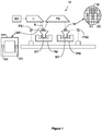
- FIG. 1 schematically shows a lithographic apparatus 10 including a source collector module SO according to an embodiment of the invention.
- the apparatus comprises: an illumination system (illuminator) IL configured to condition a radiation beam B (e.g., EUV radiation); a support structure (e.g., a mask table) MT constructed to support a patterning device (e.g., a mask or a reticle) MA and connected to a first positioner PM configured to accurately position the patterning device; a substrate table (e.g., a wafer table) WT constructed to hold a substrate (e.g., a resist-coated wafer) W and connected to a second positioner PW configured to accurately position the substrate; and a projection system (e.g., a reflective projection system) PS configured to project a pattern imparted to the radiation beam B by patterning device MA onto a target portion C (e.g., comprising one or more dies) of the substrate W.
- a radiation beam B e.g.
- the illumination system may include various types of optical components, such as refractive, reflective, magnetic, electromagnetic, electrostatic or other types of optical components, or any combination thereof, for directing, shaping, or controlling radiation.
- optical components such as refractive, reflective, magnetic, electromagnetic, electrostatic or other types of optical components, or any combination thereof, for directing, shaping, or controlling radiation.
- the support structure MT holds the patterning device MA in a manner that depends on the orientation of the patterning device, the design of the lithographic apparatus, and other conditions, such as for example whether or not the patterning device is held in a vacuum environment.
- the support structure can use mechanical, vacuum, electrostatic or other clamping techniques to hold the patterning device.
- the support structure may be a frame or a table, for example, which may be fixed or movable as required. The support structure may ensure that the patterning device is at a desired position, for example with respect to the projection system.
- patterning device should be broadly interpreted as referring to any device that can be used to impart a radiation beam with a pattern in its cross-section such as to create a pattern in a target portion of the substrate.
- the pattern imparted to the radiation beam may correspond to a particular functional layer in a device being created in the target portion, such as an integrated circuit.
- the patterning device may be reflective (as in lithographic apparatus 10 of FIG. 1 ) or transmissive.
- Examples of patterning devices include masks, programmable mirror arrays, and programmable LCD panels.
- Masks are well known in lithography, and include mask types such as binary, alternating phase-shift, and attenuated phase-shift, as well as various hybrid mask types.
- An example of a programmable mirror array employs a matrix arrangement of small mirrors, each of which can be individually tilted so as to reflect an incoming radiation beam in different directions. The tilted mirrors impart a pattern in a radiation beam which is reflected by the mirror matrix.
- the projection system may include various types of optical components, such as refractive, reflective, magnetic, electromagnetic, electrostatic or other types of optical components, or any combination thereof, as appropriate for the exposure radiation being used, or for other factors such as the use of a vacuum. It may be desired to use a vacuum for EUV radiation since other gases may absorb too much radiation. A vacuum environment may therefore be provided to the whole beam path with the aid of a vacuum wall and vacuum pumps.
- the lithographic apparatus is of a reflective type (e.g., employing a reflective mask).
- the lithographic apparatus may be of a type having two (dual stage) or more substrate tables (and/or two or more mask tables). In such "multiple stage” machines the additional tables may be used in parallel, or preparatory steps may be carried out on one or more tables while one or more other tables are being used for exposure.
- the illuminator IL receives an extreme ultra violet radiation beam from the source collector apparatus SO.
- Methods to produce EUV radiation include, but are not necessarily limited to, converting a material into a plasma state that has at least one element, e.g., xenon, lithium or tin, with one or more emission lines in the EUV range.
- LPP laser produced plasma
- the required plasma can be produced by irradiating a fuel, such as a droplet, stream or cluster of material having the required line-emitting element, with a laser beam.
- the source collector apparatus SO may be part of an EUV radiation system including a laser, not shown in FIG. 1 , for providing the laser beam exciting the fuel.
- the resulting plasma emits output radiation, e.g., EUV radiation, which is collected using a radiation collector, disposed in the source collector apparatus.
- output radiation e.g., EUV radiation
- the laser and the source collector apparatus may be separate entities, for example when a CO.sub.2 laser is used to provide the laser beam for fuel excitation.
- the laser is not considered to form part of the lithographic apparatus and the laser beam is passed from the laser to the source collector apparatus with the aid of a beam delivery system comprising, for example, suitable directing mirrors and/or a beam expander.
- the EUV emitting plasma is produced by using an electrical discharge to vaporise a fuel.
- the fuel may be an element such as xenon, lithium or tin which has one or more emission lines in the EUV range.
- the electrical discharge may be generated by a power supply which may form part of the source collector apparatus or may be a separate entity that is connected via an electrical connection to the source collector apparatus.
- the illuminator IL may comprise an adjuster for adjusting the angular intensity distribution of the radiation beam. Generally, at least the outer and/or inner radial extent (commonly referred to as .sigma.-outer and .sigma.-inner, respectively) of the intensity distribution in a pupil plane of the illuminator can be adjusted.
- the illuminator IL may comprise various other components, such as facetted field and pupil mirror devices. The illuminator may be used to condition the radiation beam, to have a desired uniformity and intensity distribution in its cross-section.
- the radiation beam B is incident on the patterning device (e.g., mask) MA, which is held on the support structure (e.g., mask table) MT, and is patterned by the patterning device. After being reflected from the patterning device (e.g., mask) MA, the radiation beam B passes through the projection system PS, which focuses the beam onto a target portion C of the substrate W.
- the substrate table WT can be moved accurately, e.g., so as to position different target portions C in the path of the radiation beam B.
- the first positioner PM and another position sensor PS1 can be used to accurately position the patterning device (e.g., mask) MA with respect to the path of the radiation beam B.
- Patterning device (e.g., mask) MA and substrate W may be aligned using mask alignment marks M1, M2 and substrate alignment marks P1, P2.
- the depicted apparatus could be used in at least one of the following modes:
- step mode the support structure (e.g., mask table) MT and the substrate table WT are kept essentially stationary, while an entire pattern imparted to the radiation beam is projected onto a target portion C at one time (i.e., a single static exposure).
- the substrate table WT is then shifted in the X and/or Y direction so that a different target portion C can be exposed.
- the support structure (e.g., mask table) MT and the substrate table WT are scanned synchronously while a pattern imparted to the radiation beam is projected onto a target portion C (i.e., a single dynamic exposure).
- the velocity and direction of the substrate table WT relative to the support structure (e.g., mask table) MT may be determined by the (de-)magnification and image reversal characteristics of the projection system PS.
- the support structure (e.g., mask table) MT is kept essentially stationary holding a programmable patterning device, and the substrate table WT is moved or scanned while a pattern imparted to the radiation beam is projected onto a target portion C.
- a pulsed radiation source is employed and the programmable patterning device is updated as required after each movement of the substrate table WT or in between successive radiation pulses during a scan.
- This mode of operation can be readily applied to maskless lithography that utilizes programmable patterning device, such as a programmable mirror array of a type as referred to above.
- FIG. 2 shows the lithographic apparatus 10 in more detail, including the source collector apparatus SO, the illumination system IL, and the projection system PS.
- the source collector apparatus SO is constructed and arranged such that a vacuum environment can be maintained in an enclosing structure 220 of the source collector apparatus SO.
- An EUV radiation emitting plasma 210 may be formed by a discharge produced plasma source. EUV radiation may be produced by a gas or vapor, for example Xe gas, Li vapor or Sn vapor in which the very hot plasma 210 is created to emit radiation in the EUV range of the electromagnetic spectrum.
- the very hot plasma 210 is created by, for example, an electrical discharge causing an at least partially ionized plasma.
- Partial pressures of, for example, 10 Pa of Xe, Li, Sn vapor or any other suitable gas or vapor may be required for efficient generation of the radiation.
- a plasma of excited tin (Sn) is provided to produce EUV radiation.
- the radiation emitted by the hot plasma 210 is passed from a source chamber 211 into a collector chamber 212 via an optional gas barrier or contaminant trap 230 (in some cases also referred to as contaminant barrier or foil trap) which is positioned in or behind an opening in source chamber 211.
- the contaminant trap 230 may include a channel structure.
- Contamination trap 230 may also include a gas barrier or a combination of a gas barrier and a channel structure.
- the contaminant trap or contaminant barrier 230 further indicated herein at least includes a channel structure, as known in the art.
- the collector chamber 212 may include a radiation collector CO which may be a so-called grazing incidence collector.
- Radiation collector CO has an upstream radiation collector side 251 and a downstream radiation collector side 252. Radiation that traverses collector CO can be reflected off a grating spectral filter 240 to be focused in a virtual source point IF.
- the virtual source point IF is commonly referred to as the intermediate focus, and the source collector apparatus is arranged such that the intermediate focus IF is located at or near an opening 219 in the enclosing structure 220.
- the virtual source point IF is an image of the radiation emitting plasma 210.
- Grating spectral filter 240 is used in particular for suppressing infra-red (IR) radiation.
- the radiation traverses the illumination system IL, which may include a facetted field mirror device 222 and a facetted pupil mirror device 224 arranged to provide a desired angular distribution of the radiation beam 221, at the patterning device MA, as well as a desired uniformity of radiation intensity at the patterning device MA.
- the illumination system IL may include a facetted field mirror device 222 and a facetted pupil mirror device 224 arranged to provide a desired angular distribution of the radiation beam 221, at the patterning device MA, as well as a desired uniformity of radiation intensity at the patterning device MA.
- the grating spectral filter 240 may optionally be present, depending upon the type of lithographic apparatus. Further, there may be more mirrors present than those shown in the Figs., for example there may be 1-6 additional reflective elements present in the projection system PS than shown in FIG. 2
- Collector optic CO is depicted as a nested collector with grazing incidence reflectors 253, 254 and 255, just as an example of a collector (or collector mirror).
- the grazing incidence reflectors 253, 254 and 255 are disposed axially symmetric around an optical axis O and a collector optic CO of this type is preferably used in combination with a discharge produced plasma source, often called a DPP source.
- Figure 3 depicts, in cross section, a clamp assembly 100 comprising an electrostatic clamp 50, also known as an e-clamp or an e-chuck, according to an embodiment of the invention.
- the clamp 50 is mounted on a substrate table WT 110 or a mask table 110.
- the clamp 50 comprises a body 45.
- the body may comprise a dielectric material.
- the body 45 may have a thickness in the region of from about 0.5 cm to about 2 cm, and preferably about 1 cm. The thickness of the body 45 is measured from an upper base surface 47 of the body 45 to a lower base surface 49 of the body 45.
- ground and zero voltage are used for convenience. It is not necessary for any part of the lithographic apparatus to be grounded or to have zero potential.
- ground and zero voltage should be interpreted to mean a voltage approximately equal to the voltage of the substrate W that is held by the clamp 50.
- the clamp 50 comprises an electrode 40 configured to impart a charge to a surface (e.g. the upper base surface 47) of the body 45.
- the clamp 50 further comprises a lower electrode 44 configured to impart a charge to a surface (e.g. the lower base surface 49) of the body 45.
- the clamp 50 comprises more than one of the electrode 40 and/or more than one of the lower electrode 44.
- the electrode 40 or/and the lower electrode 44 may, for example, comprise a plurality of conductors, such as an array of interdigitated and/or substantially parallel conductors.
- the electrode 40 and the lower electrode 44 are each for applying a potential difference between the electrode 40, 44 and the surface (e.g. the upper base surface 47 or the lower base surface 49) of the body 45.
- the potential difference may be such as to cause a charge to accumulate on the upper base surface 47, for example.
- the accumulated charge can electrostatically attract and hold a substrate W in contact with the clamp 50.
- the potential difference may be such as to cause a charge to accumulate on the lower base surface 49, for example.
- the accumulated charge can electrostatically attract and hold a substrate table WT 110 or a mask table MT 110 in contact with the clamp 50.
- the substrate W may be in close contact with the clamp 50, providing contact area and no-contact areas depending on the roughness of the materials used.
- the clamping force is located in the small no-contact areas that are formed due to the roughness of the materials. This effect is known as the Johnsen-Rahbek effect.
- a clamp that operates based on this effect may be referred to as a Johnsen-Rahbek clamp, a J-R clamp, or a JR clamp.
- the clamp 50 of the present invention is arranged to clamp the substrate W electrostatically at least partly by Johnsen-Rahbek clamping.
- the J-R attraction force increases approximately linearly with the voltage applied to the electrode 40.
- the body 45 may have a resistivity that is so high that no significant current can pass between the electrode 40 and the upper base surface 47.
- the Johnsen-Rahbek effect may not occur to any significant extent.
- an attractive force between the electrode 40 and the substrate W may still occur due to the potential difference between these elements.
- the electrode 40 and the substrate W may act as two plates of a capacitor and be attracted to each other in the same way as the two plates of a charge capacitor. Clamps/chucks that operate predominantly on this principle may be referred to as Coulombic clamps. J-R clamps will also involve some degree of attraction by the Coulombic mechanism, but the J-R effect will normally be dominant in such clamps.
- the clamp 50 of the present invention is arranged to clamp the substrate W electrostatically by Coulombic clamping.
- the electrode 40 and the lower electrode 44 may be a unipolar or bipolar respectively.
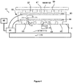
- FIG. 4 depicts, in cross section, a clamp assembly, generally denoted 100, according to an embodiment of the present invention.
- the clamp assembly 100 comprises a clamp 50, also known as a chuck.
- the clamp 50 is an electrostatic clamp.
- the clamp 50 comprises a plurality of upper burls 57 protruding above the upper base surface 47 of the clamp 50.
- Each of the plurality of upper burls 57 has a respective distal end 58.
- the plurality of upper burls 57 are arranged such that, when the substrate W is supported by the clamp 50, the substrate W is supported by the respective distal end 58 of each of the plurality of the upper burls 57.
- the contact area between the substrate W and the clamp 50 is a percentage of the total area of the upper surface of the clamp 50.
- the percentage may be in the region of from about 0.5% to about 10%, and preferably about 1.5%.
- the upper burls 57 may each have a height within the region of from about 2 ⁇ m to about 200 ⁇ m and preferably about 10 ⁇ m. The height is how far the upper burl 57 protrudes from the upper base surface 47 between the upper burls 57.
- the upper burls 57 allow backfill gas to sit between the substrate W and the clamp 50, thereby providing better thermal conductivity between the substrate W and the clamp 50.
- the region between the substrate table WT and the substrate W may be maintained at partial vacuum. Such an arrangement will tend to facilitate removal of the substrate W, for example because Van Der Waals forces acting between a substrate table WT and the substrate W are less strong.
- the clamp 50 comprises a plurality of lower burls 59 protruding below the lower base surface 49 of the clamp 50.
- Each of the plurality of lower burls 59 has a respective distal end 60.
- the plurality of lower burls 59 are arranged such that, when the clamp 50 is supported on the substrate table WT 110 or on the mask table MT 110, the clamp 50 is supported by the respective distal end 60 of each of the plurality of the lower burls 59.
- the dimensions of the lower burls 59 is the same as the dimensions of the upper burls 57.
- the lithographic apparatus comprises a controller 85.
- the lithographic apparatus comprises a power supply 80.
- the controller 85 is configured to control the power supply 80 to apply to the electrode 40 a voltage having a clamping polarity so as to provide a clamping force between the clamp 50 and the substrate W on the clamp 50.
- the clamp assembly 100 comprises a support member 110.
- This support member 110 may be the mask table 110 or the substrate table 110.
- the support member 110 is moveably coupled to a further support member 115, which may be a table, a stage, or the like.
- the clamp assembly 100 is shown coupled to, e.g. clamped to, an article 120.
- the article 120 may be a substrate, more specifically a wafer. It will be appreciated that in other embodiments falling within the scope of the present invention the clamp assembly 100 may be suitable for coupling to a patterning device MA.
- the upper or/and lower burls 140 may comprise a dielectric material, for example the same material as the body 45.
- the upper or/and lower burls 57, 59 may comprise, for example, cuboids, cylinders, pyramids, conical frustums, or the like respectively.
- the clamp 50 may comprise one or more internal channels, e.g. internal fluid channels. Such internal channels may be provided for a thermally conditioned fluid to enhance thermal transfer from the clamp 50.
- the internal fluid channels are also not shown, for purposes of simplicity.
- a fluid distribution system may be configured to condition the fluid, e.g. water or another fluid, to a desired temperature before distributing the fluid to circulate through electrostatic clamp 50.
- the thermally conditioned fluid may be circulated to help to regulate a temperature of clamp 50 and/or the article 120.
- the support member 110 may be configurable to be moved relative to the further support member 115, in order to precisely position the article 120 relative to, for example, a focal point of a radiation beam B.
- the electrostatic clamp shown in Figure 4 comprises a first fluid conduit 150 for introducing a gas, known as a backfill gas, into voids or channels 155 formed between the lower burls 59, the lower base surface 49 of the clamp 50, and an upper surface 62 of the support member 110.
- the gas may comprise hydrogen.
- the gas may comprise a relatively inert gas, such as argon or the like.
- the gas may comprise CO 2 .
- the gas may be a thermally conditioned gas, e.g. a temperature regulated gas. Such a gas may enhance thermal transfer from the clamp 50 or/and the support member 110.
- a clamping pressure e.g.
- the first fluid conduit 150 is shown forming a fluid conduit path provided with an opening 152 at the lower base surface 49 of the clamp 50. It will be appreciated that in other embodiments, other fluid conduit paths may be implemented. In an embodiment, the first fluid conduit 150 is provided with a plurality of openings 152 at the lower base surface 49 of the clamp 50.
- the openings 152 are located at a peripheral part of the lower base surface 49 of the clamp 50.
- the openings 152 may be distributed on the lower base surface 49 of the clamp 50 to ensure a gas, e.g., a humidified gas, flowing though the openings 152, comes into direct contact with all, or substantially all, of the lower base surface 49 of the clamp 50.
- one or more openings 152 may be additionally and/or alternatively located at, or substantially at, a central part of the lower base surface 49 of the clamp 50.
- the one or more openings 152 may be oriented and/or configured to radially direct a flow gas from the central part, such that substantially all of the lower base surface 49 of the clamp 50 comes into direct contact with the gas.
- the example clamp assembly 100 comprises a gas distribution system 195.
- the gas distribution system 195 is configured to supply the backfill gas to the voids or channels 155 formed between the lower burls 59, the lower base surface 49 of the clamp 50 and the upper surface 62 of the support member 110 via the first fluid conduit 150.
- Features of the gas distribution system 195 will be described in more detail with reference to Figure 5 .
- a plurality of lower burls or feet 59 are located on a lower base surface 49 of the clamp 50.
- a lower surface 60 of the burls or feet 59 defines a plane at which the clamp 50 is coupled to an upper surface 62 of the support member 110 in use.
- burls or feet 59 are shown in Figure 4 for purposes of example only, it will be appreciated that more than six burls or feet, i.e. a multiplicity of burls or feet 59, may be provided on the lower base surface 49 of the clamp 50.
- the burls or feet 155 may be distributed across the lower base surface 49 of the clamp 50.
- an electrical charge may accumulate on at least a portion of the lower base surface 49 of the clamp 50.
- a residual charge may remain on the at least a portion of the lower base surface 49 of the clamp 50.
- the residual charge may exert a repellant or an attractive force between the clamp 50 and the support member 110.
- the residual charge may be non-uniformly distributed across the lower base surface 49 of the clamp 50. Such a non-uniformly distributed residual charge may result in a deformation of the support member 110 or/and the clamp 50. Such a deformation may affect a position and/or orientation detection of the clamp assembly 100.
- the clamp assembly 100 comprises an arrangement configurable to direct a gas to the lower base surface 49 of the clamp 50 via one or more fluid conduits 150.
- the arrangement comprises a second fluid conduit 160 for introducing a humidified gas into voids or channels 155 formed between burls or feet 59, the lower base surface 49 of the clamp 50 and the upper surface 62 of the support member 110.
- the humidified gas may be a thermally conditioned gas, e.g. a temperature regulated gas.
- the second fluid conduit 160 is shown forming a fluid conduit path extending provided with an opening 162 at the upper surface 62 of the support member 110.
- the opening 162 may be located at a center part of the clamp 50.
- the second fluid conduit 160 may be connected to the gas distribution system 195 used for the first fluid conduit 150 or a separate gas distribution system.
- the assembly 100 may also comprise one or more further conduits or vents (not shown) configurable to direct the humidified gas away from the voids or channels 155formed between burls or feet 59.
- the humidified gas may be pumped away from the opening 152 or/and the opening 162.
- the gas distribution system 195 may be configured to humidify a gas to form the humidified gas.
- gas distribution system 195 may be configured to humidify backfill gas to form a humidified backfill gas.
- Figure 5 depicts features of an example embodiment of the gas distribution system 195.
- Figure 5 depicts an example arrangement 300 configurable to humidify a gas by exposing the gas to a liquid 320.
- the arrangement 300 comprises a reservoir 310.
- the reservoir 310 is configurable to contain the liquid 320.
- the liquid 320 comprises water, e.g. distilled water.
- the liquid 320 may comprise isopropanol alcohol.
- the liquid 320 may comprise or be any fluid with a conductivity of at least 1 ⁇ S/m at 25 °C
- the arrangement 300 comprises a gas supply system 305.
- the gas supply system 305 comprises a pump 330.
- the pump is configured to pump a gas, e.g. the backfill gas, into the reservoir 310 via a fluid conduit 340.
- the fluid conduit 340 is configured to expose the gas to the liquid 320 in the reservoir 310.
- the fluid conduit 340 extends below a surface of the liquid 320 in the reservoir 310. As such, gas pumped into the reservoir 310 by the pump 330 via the fluid conduit 340 is exposed to the liquid 320, and thus humidified to form a humidified gas.
- a further fluid conduit 350 is configured to direct the humidified gas from the reservoir 310 to a clamp 50.
- the clamp 50 may be, for example, a clamp 50 as described above with reference to Figure 4 .
- the fluid conduit 340 comprises a first valve 345 configurable between an open and a closed configuration. In the closed configuration, the first valve 345 inhibits flow of the gas from the gas supply system 305 into the reservoir 320. In the open configuration, the first valve 345 allows flow of the gas from the gas supply system 305 into the reservoir 320.
- the further fluid conduit 350 comprises a second valve 355 configurable between an open and a closed configuration. In the closed configuration, the second valve 355 inhibits flow of the gas from the reservoir 320 towards the clamp 50. In the open configuration, the second valve 355 inhibits flow of the gas from the reservoir 320 towards the clamp 50.
- the arrangement 300 comprises a bypass fluid conduit 380.
- the bypass fluid conduit 380 communicably couples the fluid conduit 340 and the further fluid conduit 350.
- the bypass fluid conduit 380 comprises a third valve 385 configurable between an open and a closed configuration. In the closed configuration, the third valve 385 inhibits a flow of the gas directly between the fluid conduit 340 and the further fluid conduit 350. In the open configuration, the third valve 385 allows a flow of the gas directly between the fluid conduit 340 and the further fluid conduit 350.
- the arrangement 300 is configurable to expose the gas to the liquid 320 by directing the gas through the reservoir 310.
- a gas pumped by pump 330 from the gas supply system 305 into the first fluid conduit 340 bypasses the reservoir 310 and is instead directed towards the clamp 50 by the bypass conduit and the further fluid conduit 350.
- the arrangement 300 is also configurable to direct a non-humidified gas towards the clamp 50.
- the reservoir comprises a pressure sensor 390.
- the pressure sensor 390 is configured to sense a pressure of the humidified gas in the reservoir 310.
- the pressures sensor 390 may be disposed at alternative locations within the arrangement 300 or within the clamp assembly 100.
- the pressure sensor 390 may be disposed in the gas supply system 305, in one of the fluid conduits 340, 350, 360, or within the clamp 50.
- one or more additional pressure sensors may be implemented within the arrangement 300.
- the reservoir may comprise a flow sensor (not drawn in Figure 5 ). The flow sensor is configured to sense a flow of the humidified gas in the reservoir 310.
- the flow sensor may be disposed at alternative locations within the arrangement 300 or within the clamp assembly 100.
- the flow sensor may be disposed in the gas supply system 305, in one of the fluid conduits 340, 350, 360, or within the clamp 50.
- one or more additional pressure sensors may be implemented within the arrangement 300.
- the gas supply system 305 comprises a controller 395.
- the controller 395 is communicably coupled to the pressure sensor 390 (or/and to the flow sensor).
- the controller 395 is also communicably coupled to the pump 330.
- the controller maybe configurable to control a pressure (or/and a flow) of humidified gas in the reservoir 310. That is, the controller may be configured to control, e.g. operate, the pump 330 in response to a sensed pressure by the pressure sensors 390 or/and by a sensed flow by the flow sensor.
- the first valve 345 and/or second valve 355 and/or third valve 385 is/are communicably coupled to the controller 395.
- the controller 395 may be configurable to configure each of the first valve 345 and/or second valve 355 and/or third valve 385 between the open and closed configurations.
- the pump 330 may be configured to increase or decrease a pressure of the humidified gas.
- the humidified gas when directed towards the lower base surface 49 of the clamp 50, may discharge a residual charge present of the clamp 50.
- any residual charge present on the lower base surface 49 of the clamp 50 may be removed, e.g. discharged, by the humidified gas.
- Discharging of the lower base surface 49 of the clamp 50 may be accelerated by increasing the pressure of the gas to above a first threshold, wherein the first threshold corresponds to a pressure that equals 80% of a vapor pressure of the liquid at a temperature of the lower base surface 49 of the clamp 50.
- the first threshold corresponds to a pressure that equals 90% or 100% of a vapor pressure of the liquid at a temperature of the lower base surface 49 of the clamp 50. That is, an arrangement such as gas distribution system 195 of Figure 4 , is configurable to maintain a pressure of the gas at or above the first threshold. The percentage may depend on the lower base surface condition to condense at least part of the liquid on the lower base surface 49 of the clamp 50.
- discharging of the lower base surface 49 of the clamp 50 may be at a pressure of the gas below a first threshold, namely below the vapor pressure of the liquid. That is, using partly humidified gas.
- the liquid is water
- increasing the pressure of the humidified gas to above the vapor pressure of water at a temperature of the lower base surface 49 of the clamp 50 will cause water to condense on the lower base surface 49 of the clamp 50.
- Condensation on the lower base surface 49 of the clamp 50 may accelerate discharging of the lower base surface 49 of the clamp 50, as described below with reference to Figures 6a and 6b .
- a second threshold which corresponds to a pressure sufficient to move or lift the clamp 50 with respect to the support member 110, should not be exceeded, to prevent lifting of the clamp 50 with respect to the support member 110. That is, an arrangement such as gas distribution system 195 of Figure 5 , is configurable to maintain a pressure of the gas at or below a second threshold, wherein the second threshold corresponds to a pressure sufficient to move or lift the clamp with respect to the support member 110.
- Figure 6a shows an example of a clamp 405.
- a surface 410 e.g. a lower base surface, of the clamp 405 is negatively charged, as represented by a plurality of electrons 415 accumulated at the surface 410.
- the negative charge may be a residual charge, e.g. a charge present after an article has been removed from the clamp 405.
- Figure 6b shows the portion of a clamp 405, wherein a liquid has condensed on the surface 410.
- the liquid is represented as condensed droplets 420 but may also be a condensed film.
- the liquid may be condensed on the surface 410 by increasing a pressure of a humidified gas in contact with the surface 410, e.g. a gas humidified with the liquid, until the pressure reaches, and/or exceeds a vapor pressure of the liquid at the temperature of the surface 410.
- the negative charge on the surface 410 may be at least in part, transferred to the condensed droplets 420.
- Figure 7 shows a relationship between the vapor pressure of water and the vapor pressure of isopropanol alcohol (IPA) and temperature. It can be seen, for example, that at approximately 25 degrees Celsius a vapor pressure of water is approximately 31.3 mbar. That is, at a temperature of 25 degrees Celsius it is necessary to pressurize the gas humidified with water to approximately 31.3 mbar to trigger condensation at a surface of the clamp. The vapor pressure may depend on the surface condition.
- IPA isopropanol alcohol
- a vapor pressure of IPA at 25 degrees Celsius is approximately 55 mbar.
- a liquid such as water may be selected to humidify the gas, e.g. the backfill gas, such that the gas can be pressurized to above 80%, or 90%, or 100% of the vapor pressure of the liquid without exceeding a pressure threshold at which the clamp 50 may be lifted with respect to the support member 110 or the assembly 100.
- a mixture of liquids may be employed.
- a mixture of water and IPA may be used.
- a ratio of IPA to water may be selected such that the gas can be pressurized to above the vapor pressure of the liquid mixture without exceeding a pressure threshold at which the clamp 50 may be lifted with respect to the support member 110 or the assembly 100.
- a pressure of the humidified gas may be maintained at or above a vapor pressure of the liquid used to humidify the gas for a predefined duration of time.
- the pressure may be maintained at or above the vapor pressure of the liquid for 1, 5, 10, 60 minutes, or longer, to ensure sufficient discharge of the surface of the clamp.
- the discharging technique of the lower base surface 49 of the clamp 50 may also be applied to the upper base surface 47 of the clamp 50.
- humidified gas should be directed to the upper base surface 47 of the clamp 50. This may be done through an opening on the upper base surface 47.
- Figure 8 shows a method of discharging a lower base surface of a clamp according to an embodiment of the invention.
- a gas is humidified by exposing the gas to a liquid.
- the gas may be a backfill gas.
- the gas may comprise, for example, Hydrogen, or an inert gas such as Argon.
- the gas may be humidified by exposing the gas to a liquid using the features of the gas distribution system as described above with respect to Figure 5 .
- the humidified gas is directed towards a lower base surface 49 of a clamp 50.
- One or more fluid conduits such as fluid conduit 150 as depicted in Figure 4 , and/or fluid conduit 160 as depicted in Figure 4 may direct the humidified gas to the lower base surface 49 of the clamp 50.
- a pump for example pump 330 as described with respect to Figure 5 , may be configured to pressurize the humidified gas.
- a pressure of the humidified gas may be increased or decreased to between 80% or 90% or 100% of a vapor pressure of the liquid at a temperature of the lower base surface of the clamp depending on the surface condition, and a pressure sufficient to move or lift the clamp with respect to a clamp assembly. As described above with respect to Figure 6b , the pressure may result in condensation of the liquid on the lower base surface of the clamp.
- the pressure of the gas is maintained for a duration of time. That is, the pressure of the gas is maintained, e.g. held, at a pressure between a vapor pressure of the liquid at a temperature of the lower base surface of the clamp, and a pressure sufficient to lift the clamp with respect to a clamp assembly.
- the pressure may be maintained for 1, 5, 10, 60 minutes, or longer, to ensure sufficient discharge of the clamp.
- the humidified gas is removed from the lower base surface 49 of the clamp 50.
- the humidified gas may be directed and/or pumped away from the opening 152 or/and the opening 162.
- gas which has not been humidified e.g. a non-humidified backfill gas
- the gas distribution system may be configured to provide a non-humidified gas by configuring valves such that gas from a gas supply bypasses a reservoir of liquid, thus avoiding exposing the gas to the liquid.
- clamp assembly may find utility in other apparatuses, such as an apparatus for chemical vapor deposition, atomic layer deposition, physical vapor deposition, pulsed laser deposition, molecular beam epitaxy, or the like.
- lithographic apparatus in the manufacture of ICs
- lithographic apparatus described herein may have other applications. Possible other applications include the manufacture of integrated optical systems, guidance and detection patterns for magnetic domain memories, flat-panel displays, liquid-crystal displays (LCDs), thin-film magnetic heads, etc.
- Embodiments of the invention may form part of a mask inspection apparatus, a metrology apparatus, or any apparatus that measures or processes an object such as a wafer (or other substrate) or mask (or other patterning device). These apparatus may be generally referred to as lithographic tools. Such a lithographic tool may use vacuum conditions or ambient (non-vacuum) conditions.
Landscapes
- Health & Medical Sciences (AREA)
- Physics & Mathematics (AREA)
- General Physics & Mathematics (AREA)
- Epidemiology (AREA)
- Public Health (AREA)
- Life Sciences & Earth Sciences (AREA)
- Atmospheric Sciences (AREA)
- Engineering & Computer Science (AREA)
- Environmental & Geological Engineering (AREA)
- Toxicology (AREA)
- Exposure And Positioning Against Photoresist Photosensitive Materials (AREA)
Abstract
A clamp assembly is disclosed, the clamp assembly comprising a clamp (50) configurable to clamp a support member (110) to a lower base surface (49) of the clamp by electrostatic adhesion, and an arrangement configurable to direct a gas to the lower base surface (49) of the clamp. The arrangement is configurable to humidify the gas by exposing the gas to a liquid. Also disclosed is a method of discharging a lower base surface of a clamp, The method comprises the steps of humidifying a gas by exposing the gas to a liquid, and directing the humidified gas to a lower base surface of the clamp.
Description
- The present invention relates to a clamp assembly and an associated method of use of the clamp assembly. The clamp assembly may find utility in a lithographic apparatus.
- A lithographic apparatus is a machine constructed to apply a desired pattern onto a substrate. A lithographic apparatus can be used, for example, in the manufacture of integrated circuits (ICs). A lithographic apparatus may, for example, project a pattern (also often referred to as "design layout" or "design") of a patterning device (e.g., a mask) onto a layer of radiation-sensitive material (resist) provided on a substrate (e.g., a wafer).
- As semiconductor manufacturing processes continue to advance, the dimensions of circuit elements have continually been reduced while the amount of functional elements, such as transistors, per device has been steadily increasing over decades, following a trend commonly referred to as 'Moore's law'. To keep up with Moore's law the semiconductor industry is chasing technologies that enable to create increasingly smaller features. To project a pattern on a substrate a lithographic apparatus may use electromagnetic radiation. The wavelength of this radiation determines the minimum size of features which are patterned on the substrate. Typical wavelengths currently in use are 365 nm (i-line), 248 nm, 193 nm and 13.5 nm. A lithographic apparatus, which uses extreme ultraviolet (EUV) radiation, having a wavelength within a range of 4 nm to 20 nm, for example 6.7 nm or 13.5 nm, may be used to form smaller features on a substrate than a lithographic apparatus which uses, for example, radiation with a wavelength of 193 nm.
- At such short wavelengths, precise positioning of the patterning device and/or substrate within the lithographic apparatus is essential.
- Such lithographic apparatuses may be provided with one or more clamps to clamp the patterning device and/or substrate to an object support, such as a mask table or a wafer table respectively. The clamp may be, for example, a mechanical clamp, a vacuum clamp, or an electrostatic clamp. Electrostatic clamps may be particularly suited to operating at EUV wavelengths, since regions of an EUV lithographic apparatus necessarily operate under near vacuum conditions.
- Electrostatic clamps are often maintained in a low-pressure hydrogen-rich environment, which is a generally non-conductive environment. As such, electric charge may accumulate on dielectric or ungrounded surfaces of the clamp. The accumulated charge may be non-uniformly distributed across the surfaces. Such non-uniformly distributed accumulated charge may have detrimental effects on the general operation of the lithographic apparatus. For example, a non-uniformly distributed charge on a charged surface of a clamp may result in unwanted deformation of components of the lithographic apparatus in relatively close proximity to the clamp, potentially affecting precise positioning of the patterning device and/or substrate within the lithographic apparatus.
- It is an object of at least one embodiment of at least one aspect of the present invention to obviate or at least mitigate at least one of the above identified shortcomings of the prior art.
- According to an aspect of the present invention, there is provided a clamp assembly, the clamp assembly comprising a clamp configurable to clamp a support member to a lower base surface of the clamp by electrostatic adhesion, and an arrangement configurable to direct a gas to the lower base surface of the clamp, wherein the arrangement is configurable to humidify the gas by exposing the gas to a liquid.
- Advantageously, a humidified gas may more effectively discharge the lower base surface of the clamp than a non-humidified gas.
- The clamp may be configurable to clamp an article to an upper base surface of the clamp by electrostatic adhesion. Advantageously, this electrostatic clamping may enable clamping a substrate in vacuum.
- The arrangement may be configurable to condense at least a part of the liquid on the lower base surface of the clamp and to remove the at least a part of the liquid from the lower base surface of the clamp. The arrangement may be configurable to maintain a pressure of the gas at or above a first threshold, wherein the first threshold corresponds to a pressure that equals 80% of a vapor pressure of the liquid at a temperature of the lower base surface of the clamp. Alternatively the first threshold may correspond to a pressure that equals 90% or 100% of a vapor pressure of the liquid at a temperature of the lower base surface of the clamp. The percentage may depend on the lower base surface condition to condense at least part of the liquid on the lower base surface of the clamp.
- Advantageously, maintaining a pressure of the gas at or above this threshold may result in condensation of the liquid forming on the lower base surface of the clamp, which may accelerate discharging of the lower base surface.
- The arrangement may be configurable to maintain a pressure of the gas at or below a second threshold, wherein the second threshold corresponds to a pressure sufficient to move or lift the clamp with respect to the assembly.
- The arrangement may be configurable to remove the humidified gas from the lower base surface of the clamp.
- Advantageously, this may remove a residual charge from the lower base surface of the clamp.
- The lower base surface of the clamp may be provided with an opening configured to direct the humidified gas out of the opening.
- The arrangement may comprise a pump. The arrangement may comprise at least one pressure sensor. The arrangement may comprise a controller. The controller may be communicably coupled to the pump and the pressure sensor.
- The arrangement may comprise a reservoir for the liquid. The arrangement may be configurable to expose the gas to the liquid by directing the gas through the reservoir.
- The lower base surface of the clamp may comprise at least one burl. The at least one burl may define at least one channel between the clamp and a support member.
- An upper surface of the support member may be provided with an opening configured to direct the humidified gas out of the opening.
- The clamp assembly may comprise one or more fluid conduits. The arrangement may be configurable to direct the gas into the at least one channel via the one or more fluid conduits.
- The clamp may be configurable to be coupled to the support member by electrostatic adhesion.
- According to a further aspect of the present invention, there is provided a method of discharging a lower base surface of a clamp, wherein the clamp is configurable to clamp a support member to the lower base surface of the clamp by electrostatic adhesion, and wherein the method comprises the steps of: humidifying the gas by exposing the gas to a liquid; and directing the humidified gas to the lower base surface of the clamp.
- The method may further comprises a step of pressurizing the gas to between a first and a second threshold, wherein the first threshold is 80% or 90% or 100% of a vapor pressure of the gas at a temperature of the lower base surface of the clamp, and the second threshold is a pressure sufficient to move or lift the clamp with respect to the support member or the assembly.
- The method may further comprise a step, e.g. a subsequent step, of removing the humidified gas from the lower base surface of the clamp.
- The step of exposing the gas to a liquid may comprise directing the gas through a reservoir of the liquid.
- The liquid may comprises at least one of water and/or isopropanol alcohol.
- The lower base surface of the clamp may be discharged after the article has been removed from the upper base surface of the clamp.
- Embodiments of the invention will now be described, by way of example only, with reference to the accompanying schematic drawings, in which:
-
Figure 1 depicts a schematic overview of a lithographic apparatus; -
Figure 2 depicts a schematic overview of a lithographic apparatus; -
Figure 3 depicts a cross sectional view of a clamp assembly according to an embodiment of the invention; -
Figure 4 depicts a cross sectional view of a clamp assembly according to an embodiment of the invention; -
Figure 5 depicts features of a gas distribution system according to an embodiment of the invention; -
Figures 6a-b are a sequence of diagrams depicting discharging of a surface of a clamp; -
Figure 7 is a graph showing a relationship between the vapor pressure of water and isopropanol alcohol (IPA) and temperature; and -
Figure 8 is a flow diagram of discharging a lower base surface of a clamp according to an embodiment of the invention. - In the present document, the terms "radiation" and "beam" are used to encompass all types of electromagnetic radiation, including ultraviolet radiation (e.g. with a wavelength of 365, 248, 193, 157 or 126 nm) and EUV (extreme ultra-violet radiation, e.g. having a wavelength in the range of about 5-100 nm).
- The term "reticle", "mask" or "patterning device" as employed in this text may be broadly interpreted as referring to a generic patterning device that can be used to endow an incoming radiation beam with a patterned cross-section, corresponding to a pattern that is to be created in a target portion of the substrate. The term "light valve" can also be used in this context. Besides the classic mask (transmissive or reflective, binary, phase-shifting, hybrid, etc.), examples of other such patterning devices include a programmable mirror array and a programmable LCD array.
-
FIG. 1 schematically shows alithographic apparatus 10 including a source collector module SO according to an embodiment of the invention. The apparatus comprises: an illumination system (illuminator) IL configured to condition a radiation beam B (e.g., EUV radiation); a support structure (e.g., a mask table) MT constructed to support a patterning device (e.g., a mask or a reticle) MA and connected to a first positioner PM configured to accurately position the patterning device; a substrate table (e.g., a wafer table) WT constructed to hold a substrate (e.g., a resist-coated wafer) W and connected to a second positioner PW configured to accurately position the substrate; and a projection system (e.g., a reflective projection system) PS configured to project a pattern imparted to the radiation beam B by patterning device MA onto a target portion C (e.g., comprising one or more dies) of the substrate W. - The illumination system may include various types of optical components, such as refractive, reflective, magnetic, electromagnetic, electrostatic or other types of optical components, or any combination thereof, for directing, shaping, or controlling radiation.
- The support structure MT holds the patterning device MA in a manner that depends on the orientation of the patterning device, the design of the lithographic apparatus, and other conditions, such as for example whether or not the patterning device is held in a vacuum environment. The support structure can use mechanical, vacuum, electrostatic or other clamping techniques to hold the patterning device. The support structure may be a frame or a table, for example, which may be fixed or movable as required. The support structure may ensure that the patterning device is at a desired position, for example with respect to the projection system.
- The term "patterning device" should be broadly interpreted as referring to any device that can be used to impart a radiation beam with a pattern in its cross-section such as to create a pattern in a target portion of the substrate. The pattern imparted to the radiation beam may correspond to a particular functional layer in a device being created in the target portion, such as an integrated circuit.
- The patterning device may be reflective (as in
lithographic apparatus 10 ofFIG. 1 ) or transmissive. Examples of patterning devices include masks, programmable mirror arrays, and programmable LCD panels. Masks are well known in lithography, and include mask types such as binary, alternating phase-shift, and attenuated phase-shift, as well as various hybrid mask types. An example of a programmable mirror array employs a matrix arrangement of small mirrors, each of which can be individually tilted so as to reflect an incoming radiation beam in different directions. The tilted mirrors impart a pattern in a radiation beam which is reflected by the mirror matrix. - The projection system, like the illumination system, may include various types of optical components, such as refractive, reflective, magnetic, electromagnetic, electrostatic or other types of optical components, or any combination thereof, as appropriate for the exposure radiation being used, or for other factors such as the use of a vacuum. It may be desired to use a vacuum for EUV radiation since other gases may absorb too much radiation. A vacuum environment may therefore be provided to the whole beam path with the aid of a vacuum wall and vacuum pumps.
- As here depicted, the lithographic apparatus is of a reflective type (e.g., employing a reflective mask).
- The lithographic apparatus may be of a type having two (dual stage) or more substrate tables (and/or two or more mask tables). In such "multiple stage" machines the additional tables may be used in parallel, or preparatory steps may be carried out on one or more tables while one or more other tables are being used for exposure.
- Referring to
FIG. 1 , the illuminator IL receives an extreme ultra violet radiation beam from the source collector apparatus SO. Methods to produce EUV radiation include, but are not necessarily limited to, converting a material into a plasma state that has at least one element, e.g., xenon, lithium or tin, with one or more emission lines in the EUV range. In one such method, often termed laser produced plasma ("LPP") the required plasma can be produced by irradiating a fuel, such as a droplet, stream or cluster of material having the required line-emitting element, with a laser beam. The source collector apparatus SO may be part of an EUV radiation system including a laser, not shown inFIG. 1 , for providing the laser beam exciting the fuel. The resulting plasma emits output radiation, e.g., EUV radiation, which is collected using a radiation collector, disposed in the source collector apparatus. The laser and the source collector apparatus may be separate entities, for example when a CO.sub.2 laser is used to provide the laser beam for fuel excitation. - In such cases, the laser is not considered to form part of the lithographic apparatus and the laser beam is passed from the laser to the source collector apparatus with the aid of a beam delivery system comprising, for example, suitable directing mirrors and/or a beam expander.
- In an alternative method, often termed discharge produced plasma ("DPP") the EUV emitting plasma is produced by using an electrical discharge to vaporise a fuel. The fuel may be an element such as xenon, lithium or tin which has one or more emission lines in the EUV range. The electrical discharge may be generated by a power supply which may form part of the source collector apparatus or may be a separate entity that is connected via an electrical connection to the source collector apparatus.
- The illuminator IL may comprise an adjuster for adjusting the angular intensity distribution of the radiation beam. Generally, at least the outer and/or inner radial extent (commonly referred to as .sigma.-outer and .sigma.-inner, respectively) of the intensity distribution in a pupil plane of the illuminator can be adjusted. In addition, the illuminator IL may comprise various other components, such as facetted field and pupil mirror devices. The illuminator may be used to condition the radiation beam, to have a desired uniformity and intensity distribution in its cross-section.
- The radiation beam B is incident on the patterning device (e.g., mask) MA, which is held on the support structure (e.g., mask table) MT, and is patterned by the patterning device. After being reflected from the patterning device (e.g., mask) MA, the radiation beam B passes through the projection system PS, which focuses the beam onto a target portion C of the substrate W. With the aid of the second positioner PW and position sensor PS2 (e.g., an interferometric device, linear encoder or capacitive sensor), the substrate table WT can be moved accurately, e.g., so as to position different target portions C in the path of the radiation beam B. Similarly, the first positioner PM and another position sensor PS1 can be used to accurately position the patterning device (e.g., mask) MA with respect to the path of the radiation beam B. Patterning device (e.g., mask) MA and substrate W may be aligned using mask alignment marks M1, M2 and substrate alignment marks P1, P2.
- The depicted apparatus could be used in at least one of the following modes:
- In step mode, the support structure (e.g., mask table) MT and the substrate table WT are kept essentially stationary, while an entire pattern imparted to the radiation beam is projected onto a target portion C at one time (i.e., a single static exposure). The substrate table WT is then shifted in the X and/or Y direction so that a different target portion C can be exposed.
- In scan mode, the support structure (e.g., mask table) MT and the substrate table WT are scanned synchronously while a pattern imparted to the radiation beam is projected onto a target portion C (i.e., a single dynamic exposure). The velocity and direction of the substrate table WT relative to the support structure (e.g., mask table) MT may be determined by the (de-)magnification and image reversal characteristics of the projection system PS.
- In another mode, the support structure (e.g., mask table) MT is kept essentially stationary holding a programmable patterning device, and the substrate table WT is moved or scanned while a pattern imparted to the radiation beam is projected onto a target portion C. In this mode, generally a pulsed radiation source is employed and the programmable patterning device is updated as required after each movement of the substrate table WT or in between successive radiation pulses during a scan. This mode of operation can be readily applied to maskless lithography that utilizes programmable patterning device, such as a programmable mirror array of a type as referred to above.
- Combinations and/or variations on the above described modes of use or entirely different modes of use may also be employed.
-
FIG. 2 shows thelithographic apparatus 10 in more detail, including the source collector apparatus SO, the illumination system IL, and the projection system PS. The source collector apparatus SO is constructed and arranged such that a vacuum environment can be maintained in an enclosingstructure 220 of the source collector apparatus SO. An EUVradiation emitting plasma 210 may be formed by a discharge produced plasma source. EUV radiation may be produced by a gas or vapor, for example Xe gas, Li vapor or Sn vapor in which the veryhot plasma 210 is created to emit radiation in the EUV range of the electromagnetic spectrum. The veryhot plasma 210 is created by, for example, an electrical discharge causing an at least partially ionized plasma. Partial pressures of, for example, 10 Pa of Xe, Li, Sn vapor or any other suitable gas or vapor may be required for efficient generation of the radiation. In an embodiment, a plasma of excited tin (Sn) is provided to produce EUV radiation. - The radiation emitted by the
hot plasma 210 is passed from asource chamber 211 into acollector chamber 212 via an optional gas barrier or contaminant trap 230 (in some cases also referred to as contaminant barrier or foil trap) which is positioned in or behind an opening insource chamber 211. Thecontaminant trap 230 may include a channel structure.Contamination trap 230 may also include a gas barrier or a combination of a gas barrier and a channel structure. The contaminant trap orcontaminant barrier 230 further indicated herein at least includes a channel structure, as known in the art. - The
collector chamber 212 may include a radiation collector CO which may be a so-called grazing incidence collector. Radiation collector CO has an upstreamradiation collector side 251 and a downstreamradiation collector side 252. Radiation that traverses collector CO can be reflected off a gratingspectral filter 240 to be focused in a virtual source point IF. The virtual source point IF is commonly referred to as the intermediate focus, and the source collector apparatus is arranged such that the intermediate focus IF is located at or near anopening 219 in the enclosingstructure 220. The virtual source point IF is an image of theradiation emitting plasma 210. Gratingspectral filter 240 is used in particular for suppressing infra-red (IR) radiation. - Subsequently the radiation traverses the illumination system IL, which may include a facetted
field mirror device 222 and a facettedpupil mirror device 224 arranged to provide a desired angular distribution of theradiation beam 221, at the patterning device MA, as well as a desired uniformity of radiation intensity at the patterning device MA. Upon reflection of the beam ofradiation 221 at the patterning device MA, held by the support structure MT, apatterned beam 226 is formed and the patternedbeam 226 is imaged by the projection system PS viareflective elements - More elements than shown may generally be present in illumination optics unit IL and projection system PS. The grating
spectral filter 240 may optionally be present, depending upon the type of lithographic apparatus. Further, there may be more mirrors present than those shown in the Figs., for example there may be 1-6 additional reflective elements present in the projection system PS than shown inFIG. 2 - Collector optic CO, as illustrated in
FIG. 2 , is depicted as a nested collector withgrazing incidence reflectors grazing incidence reflectors -
Figure 3 depicts, in cross section, aclamp assembly 100 comprising anelectrostatic clamp 50, also known as an e-clamp or an e-chuck, according to an embodiment of the invention. In the embodiment shown, theclamp 50 is mounted on asubstrate table WT 110 or a mask table 110. In an embodiment theclamp 50 comprises abody 45. The body may comprise a dielectric material. Thebody 45 may have a thickness in the region of from about 0.5 cm to about 2 cm, and preferably about 1 cm. The thickness of thebody 45 is measured from anupper base surface 47 of thebody 45 to alower base surface 49 of thebody 45. - In the following description, the terms ground and zero voltage are used for convenience. It is not necessary for any part of the lithographic apparatus to be grounded or to have zero potential. The terms ground and zero voltage should be interpreted to mean a voltage approximately equal to the voltage of the substrate W that is held by the
clamp 50. - In an embodiment the
clamp 50 comprises anelectrode 40 configured to impart a charge to a surface (e.g. the upper base surface 47) of thebody 45. In an embodiment theclamp 50 further comprises alower electrode 44 configured to impart a charge to a surface (e.g. the lower base surface 49) of thebody 45. In an embodiment theclamp 50 comprises more than one of theelectrode 40 and/or more than one of thelower electrode 44. Theelectrode 40 or/and thelower electrode 44 may, for example, comprise a plurality of conductors, such as an array of interdigitated and/or substantially parallel conductors. - The
electrode 40 and thelower electrode 44 are each for applying a potential difference between theelectrode upper base surface 47 or the lower base surface 49) of thebody 45. The potential difference may be such as to cause a charge to accumulate on theupper base surface 47, for example. The accumulated charge can electrostatically attract and hold a substrate W in contact with theclamp 50. In a similar way the potential difference may be such as to cause a charge to accumulate on thelower base surface 49, for example. The accumulated charge can electrostatically attract and hold asubstrate table WT 110 or amask table MT 110 in contact with theclamp 50. In particular the substrate W may be in close contact with theclamp 50, providing contact area and no-contact areas depending on the roughness of the materials used. The clamping force is located in the small no-contact areas that are formed due to the roughness of the materials. This effect is known as the Johnsen-Rahbek effect. A clamp that operates based on this effect may be referred to as a Johnsen-Rahbek clamp, a J-R clamp, or a JR clamp. In an embodiment theclamp 50 of the present invention is arranged to clamp the substrate W electrostatically at least partly by Johnsen-Rahbek clamping. The J-R attraction force increases approximately linearly with the voltage applied to theelectrode 40. - In an embodiment, the
body 45 may have a resistivity that is so high that no significant current can pass between theelectrode 40 and theupper base surface 47. In this case, the Johnsen-Rahbek effect may not occur to any significant extent. However, an attractive force between theelectrode 40 and the substrate W may still occur due to the potential difference between these elements. Theelectrode 40 and the substrate W may act as two plates of a capacitor and be attracted to each other in the same way as the two plates of a charge capacitor. Clamps/chucks that operate predominantly on this principle may be referred to as Coulombic clamps. J-R clamps will also involve some degree of attraction by the Coulombic mechanism, but the J-R effect will normally be dominant in such clamps. In an embodiment theclamp 50 of the present invention is arranged to clamp the substrate W electrostatically by Coulombic clamping. Theelectrode 40 and thelower electrode 44 may be a unipolar or bipolar respectively. -
Figure 4 depicts, in cross section, a clamp assembly, generally denoted 100, according to an embodiment of the present invention. In an embodiment theclamp assembly 100 comprises aclamp 50, also known as a chuck. Theclamp 50 is an electrostatic clamp. Theclamp 50 comprises a plurality ofupper burls 57 protruding above theupper base surface 47 of theclamp 50. Each of the plurality ofupper burls 57 has a respectivedistal end 58. The plurality ofupper burls 57 are arranged such that, when the substrate W is supported by theclamp 50, the substrate W is supported by the respectivedistal end 58 of each of the plurality of theupper burls 57. - An advantage of the
upper burls 57 is that they reduce the impact of contaminant particles on substrate flatness. This is because a particle can only cause a deformation of the flatness when on Nupper burls 57, unless the particle is larger than the gap between theclamp 50 and the substrate W. In such an embodiment the contact area between the substrate W and theclamp 50 is a percentage of the total area of the upper surface of theclamp 50. For example the percentage may be in the region of from about 0.5% to about 10%, and preferably about 1.5%. In an embodiment theupper burls 57 may each have a height within the region of from about 2 µm to about 200 µm and preferably about 10 µm. The height is how far theupper burl 57 protrudes from theupper base surface 47 between theupper burls 57. - Another advantage of the
upper burls 57 is that they allow backfill gas to sit between the substrate W and theclamp 50, thereby providing better thermal conductivity between the substrate W and theclamp 50. In such an embodiment, the region between the substrate table WT and the substrate W may be maintained at partial vacuum. Such an arrangement will tend to facilitate removal of the substrate W, for example because Van Der Waals forces acting between a substrate table WT and the substrate W are less strong. - In an embodiment the
clamp 50 comprises a plurality oflower burls 59 protruding below thelower base surface 49 of theclamp 50. Each of the plurality oflower burls 59 has a respectivedistal end 60. The plurality oflower burls 59 are arranged such that, when theclamp 50 is supported on thesubstrate table WT 110 or on themask table MT 110, theclamp 50 is supported by the respectivedistal end 60 of each of the plurality of thelower burls 59. In an embodiment the dimensions of thelower burls 59 is the same as the dimensions of theupper burls 57. - In an embodiment the lithographic apparatus comprises a
controller 85. In an embodiment the lithographic apparatus comprises apower supply 80. In an embodiment thecontroller 85 is configured to control thepower supply 80 to apply to the electrode 40 a voltage having a clamping polarity so as to provide a clamping force between theclamp 50 and the substrate W on theclamp 50. - The
clamp assembly 100 comprises asupport member 110. Thissupport member 110 may be the mask table 110 or the substrate table 110. Thesupport member 110 is moveably coupled to afurther support member 115, which may be a table, a stage, or the like. - For purposes of example, the
clamp assembly 100 is shown coupled to, e.g. clamped to, anarticle 120. Thearticle 120 may be a substrate, more specifically a wafer. It will be appreciated that in other embodiments falling within the scope of the present invention theclamp assembly 100 may be suitable for coupling to a patterning device MA. - The upper or/and lower burls 140 may comprise a dielectric material, for example the same material as the
body 45. The upper or/andlower burls - It will be appreciated that many features of the
clamp assembly 100, and in particular of theclamp 50 have been omitted fromFigure 4 for purposes of simplicity. For example, features such as electrical wiring and any additional electrodes have been omitted. - In some embodiments, the
clamp 50 may comprise one or more internal channels, e.g. internal fluid channels. Such internal channels may be provided for a thermally conditioned fluid to enhance thermal transfer from theclamp 50. The internal fluid channels are also not shown, for purposes of simplicity. A fluid distribution system may be configured to condition the fluid, e.g. water or another fluid, to a desired temperature before distributing the fluid to circulate throughelectrostatic clamp 50. The thermally conditioned fluid may be circulated to help to regulate a temperature ofclamp 50 and/or thearticle 120. - The
support member 110 may be configurable to be moved relative to thefurther support member 115, in order to precisely position thearticle 120 relative to, for example, a focal point of a radiation beam B. - The electrostatic clamp shown in
Figure 4 comprises a firstfluid conduit 150 for introducing a gas, known as a backfill gas, into voids orchannels 155 formed between thelower burls 59, thelower base surface 49 of theclamp 50, and anupper surface 62 of thesupport member 110. The gas may comprise hydrogen. The gas may comprise a relatively inert gas, such as argon or the like. The gas may comprise CO2. The gas may be a thermally conditioned gas, e.g. a temperature regulated gas. Such a gas may enhance thermal transfer from theclamp 50 or/and thesupport member 110. A clamping pressure, e.g. a pressure acting upon thesupport member 110 to hold theclamp 50 against thesupport member 110 due to electrostatic forces, is larger than a pressure of the gas, in order to fix theclamp 50 to thesupport member 110 . In some instances, temporary increases in the gas pressure may beneficially assist releasing of theclamp 50 from thesupport member 110. For purposes of example only, the firstfluid conduit 150 is shown forming a fluid conduit path provided with anopening 152 at thelower base surface 49 of theclamp 50. It will be appreciated that in other embodiments, other fluid conduit paths may be implemented. In an embodiment, the firstfluid conduit 150 is provided with a plurality ofopenings 152 at thelower base surface 49 of theclamp 50. In the example embodiment depicted inFigure 4 , theopenings 152 are located at a peripheral part of thelower base surface 49 of theclamp 50. Theopenings 152 may be distributed on thelower base surface 49 of theclamp 50 to ensure a gas, e.g., a humidified gas, flowing though theopenings 152, comes into direct contact with all, or substantially all, of thelower base surface 49 of theclamp 50. In a further example embodiment, one ormore openings 152 may be additionally and/or alternatively located at, or substantially at, a central part of thelower base surface 49 of theclamp 50. The one ormore openings 152 may be oriented and/or configured to radially direct a flow gas from the central part, such that substantially all of thelower base surface 49 of theclamp 50 comes into direct contact with the gas. - The
example clamp assembly 100 comprises agas distribution system 195. Thegas distribution system 195 is configured to supply the backfill gas to the voids orchannels 155 formed between thelower burls 59, thelower base surface 49 of theclamp 50 and theupper surface 62 of thesupport member 110 via the firstfluid conduit 150. Features of thegas distribution system 195 will be described in more detail with reference toFigure 5 . - A plurality of lower burls or
feet 59 are located on alower base surface 49 of theclamp 50. Alower surface 60 of the burls orfeet 59 defines a plane at which theclamp 50 is coupled to anupper surface 62 of thesupport member 110 in use. Although only six burls orfeet 59 are shown inFigure 4 for purposes of example only, it will be appreciated that more than six burls or feet, i.e. a multiplicity of burls orfeet 59, may be provided on thelower base surface 49 of theclamp 50. The burls orfeet 155 may be distributed across thelower base surface 49 of theclamp 50. - In use, an electrical charge may accumulate on at least a portion of the
lower base surface 49 of theclamp 50. Upon removal of the voltage applied to thelower electrode 44, a residual charge may remain on the at least a portion of thelower base surface 49 of theclamp 50. The residual charge may exert a repellant or an attractive force between theclamp 50 and thesupport member 110. Furthermore, the residual charge may be non-uniformly distributed across thelower base surface 49 of theclamp 50. Such a non-uniformly distributed residual charge may result in a deformation of thesupport member 110 or/and theclamp 50. Such a deformation may affect a position and/or orientation detection of theclamp assembly 100. - In an embodiment of the invention, the
clamp assembly 100 comprises an arrangement configurable to direct a gas to thelower base surface 49 of theclamp 50 via one or morefluid conduits 150. In the example embodiment ofFigure 4 , the arrangement comprises a secondfluid conduit 160 for introducing a humidified gas into voids orchannels 155 formed between burls orfeet 59, thelower base surface 49 of theclamp 50 and theupper surface 62 of thesupport member 110. The humidified gas may be a thermally conditioned gas, e.g. a temperature regulated gas. The secondfluid conduit 160 is shown forming a fluid conduit path extending provided with anopening 162 at theupper surface 62 of thesupport member 110. Theopening 162 may be located at a center part of theclamp 50. The secondfluid conduit 160 may be connected to thegas distribution system 195 used for the firstfluid conduit 150 or a separate gas distribution system. - The
assembly 100 may also comprise one or more further conduits or vents (not shown) configurable to direct the humidified gas away from the voids or channels 155formed between burls orfeet 59. In an embodiment, the humidified gas may be pumped away from theopening 152 or/and theopening 162. - The
gas distribution system 195 may be configured to humidify a gas to form the humidified gas. For example,gas distribution system 195 may be configured to humidify backfill gas to form a humidified backfill gas. -
Figure 5 depicts features of an example embodiment of thegas distribution system 195. In particular,Figure 5 depicts anexample arrangement 300 configurable to humidify a gas by exposing the gas to a liquid 320. Thearrangement 300 comprises areservoir 310. Thereservoir 310 is configurable to contain the liquid 320. Preferably, the liquid 320 comprises water, e.g. distilled water. The liquid 320 may comprise isopropanol alcohol. Alternatively the liquid 320 may comprise or be any fluid with a conductivity of at least 1 µS/m at 25 °C - The
arrangement 300 comprises agas supply system 305. Thegas supply system 305 comprises apump 330. The pump is configured to pump a gas, e.g. the backfill gas, into thereservoir 310 via afluid conduit 340. Preferably, thefluid conduit 340 is configured to expose the gas to the liquid 320 in thereservoir 310. In the example embodiment ofFigure 5 , thefluid conduit 340 extends below a surface of the liquid 320 in thereservoir 310. As such, gas pumped into thereservoir 310 by thepump 330 via thefluid conduit 340 is exposed to the liquid 320, and thus humidified to form a humidified gas. - A further
fluid conduit 350 is configured to direct the humidified gas from thereservoir 310 to aclamp 50. Theclamp 50 may be, for example, aclamp 50 as described above with reference toFigure 4 . - The
fluid conduit 340 comprises afirst valve 345 configurable between an open and a closed configuration. In the closed configuration, thefirst valve 345 inhibits flow of the gas from thegas supply system 305 into thereservoir 320. In the open configuration, thefirst valve 345 allows flow of the gas from thegas supply system 305 into thereservoir 320. - The further
fluid conduit 350 comprises asecond valve 355 configurable between an open and a closed configuration. In the closed configuration, thesecond valve 355 inhibits flow of the gas from thereservoir 320 towards theclamp 50. In the open configuration, thesecond valve 355 inhibits flow of the gas from thereservoir 320 towards theclamp 50. - The
arrangement 300 comprises abypass fluid conduit 380. Thebypass fluid conduit 380 communicably couples thefluid conduit 340 and the furtherfluid conduit 350. Thebypass fluid conduit 380 comprises athird valve 385 configurable between an open and a closed configuration. In the closed configuration, thethird valve 385 inhibits a flow of the gas directly between thefluid conduit 340 and the furtherfluid conduit 350. In the open configuration, thethird valve 385 allows a flow of the gas directly between thefluid conduit 340 and the furtherfluid conduit 350. - As such, by configuring the first and second valves in the open configuration and the third valve in the closed configuration, a gas pumped by
pump 330 from thegas supply system 305 into the firstfluid conduit 340 is humidified by the liquid 320 in thereservoir 310 before being directed towards theclamp 50 by the furtherfluid conduit 350. That is, thearrangement 300 is configurable to expose the gas to the liquid 320 by directing the gas through thereservoir 310. Alternatively, by configuring the first and second valves in the closed configuration and the third valve in the open configuration, a gas pumped bypump 330 from thegas supply system 305 into the firstfluid conduit 340 bypasses thereservoir 310 and is instead directed towards theclamp 50 by the bypass conduit and the furtherfluid conduit 350. As such, thearrangement 300 is also configurable to direct a non-humidified gas towards theclamp 50. - In an example embodiment, the reservoir comprises a
pressure sensor 390. Thepressure sensor 390 is configured to sense a pressure of the humidified gas in thereservoir 310. - It will be appreciated that in other embodiments the
pressures sensor 390 may be disposed at alternative locations within thearrangement 300 or within theclamp assembly 100. For example, thepressure sensor 390 may be disposed in thegas supply system 305, in one of thefluid conduits clamp 50. Furthermore, one or more additional pressure sensors may be implemented within thearrangement 300. In an embodiment, the reservoir may comprise a flow sensor (not drawn inFigure 5 ). The flow sensor is configured to sense a flow of the humidified gas in thereservoir 310. It will be appreciated that in other embodiments the flow sensor may be disposed at alternative locations within thearrangement 300 or within theclamp assembly 100. For example, the flow sensor may be disposed in thegas supply system 305, in one of thefluid conduits clamp 50. Furthermore, one or more additional pressure sensors may be implemented within thearrangement 300. - The
gas supply system 305 comprises acontroller 395. Thecontroller 395 is communicably coupled to the pressure sensor 390 (or/and to the flow sensor). Thecontroller 395 is also communicably coupled to thepump 330. As such, the controller maybe configurable to control a pressure (or/and a flow) of humidified gas in thereservoir 310. That is, the controller may be configured to control, e.g. operate, thepump 330 in response to a sensed pressure by thepressure sensors 390 or/and by a sensed flow by the flow sensor. - Furthermore, in some embodiments, the
first valve 345 and/orsecond valve 355 and/orthird valve 385 is/are communicably coupled to thecontroller 395. As such, thecontroller 395 may be configurable to configure each of thefirst valve 345 and/orsecond valve 355 and/orthird valve 385 between the open and closed configurations. - In use, the
pump 330 may be configured to increase or decrease a pressure of the humidified gas. - The humidified gas, when directed towards the
lower base surface 49 of theclamp 50, may discharge a residual charge present of theclamp 50. In particular, after anarticle 120 has been removed from theclamp assembly 100, any residual charge present on thelower base surface 49 of theclamp 50 may be removed, e.g. discharged, by the humidified gas. - Discharging of the
lower base surface 49 of theclamp 50 may be accelerated by increasing the pressure of the gas to above a first threshold, wherein the first threshold corresponds to a pressure that equals 80% of a vapor pressure of the liquid at a temperature of thelower base surface 49 of theclamp 50. Alternatively, the first threshold corresponds to a pressure that equals 90% or 100% of a vapor pressure of the liquid at a temperature of thelower base surface 49 of theclamp 50. That is, an arrangement such asgas distribution system 195 ofFigure 4 , is configurable to maintain a pressure of the gas at or above the first threshold. The percentage may depend on the lower base surface condition to condense at least part of the liquid on thelower base surface 49 of theclamp 50. - In an embodiment, discharging of the
lower base surface 49 of theclamp 50 may be at a pressure of the gas below a first threshold, namely below the vapor pressure of the liquid. That is, using partly humidified gas. - In an example embodiment wherein the liquid is water, increasing the pressure of the humidified gas to above the vapor pressure of water at a temperature of the
lower base surface 49 of theclamp 50 will cause water to condense on thelower base surface 49 of theclamp 50. Condensation on thelower base surface 49 of theclamp 50 may accelerate discharging of thelower base surface 49 of theclamp 50, as described below with reference toFigures 6a and 6b . - When increasing the pressure of the gas to above a first threshold, a second threshold which corresponds to a pressure sufficient to move or lift the
clamp 50 with respect to thesupport member 110, should not be exceeded, to prevent lifting of theclamp 50 with respect to thesupport member 110. That is, an arrangement such asgas distribution system 195 ofFigure 5 , is configurable to maintain a pressure of the gas at or below a second threshold, wherein the second threshold corresponds to a pressure sufficient to move or lift the clamp with respect to thesupport member 110. -
Figure 6a shows an example of aclamp 405. Asurface 410, e.g. a lower base surface, of theclamp 405 is negatively charged, as represented by a plurality ofelectrons 415 accumulated at thesurface 410. The negative charge may be a residual charge, e.g. a charge present after an article has been removed from theclamp 405. -
Figure 6b shows the portion of aclamp 405, wherein a liquid has condensed on thesurface 410. The liquid is represented as condenseddroplets 420 but may also be a condensed film. The liquid may be condensed on thesurface 410 by increasing a pressure of a humidified gas in contact with thesurface 410, e.g. a gas humidified with the liquid, until the pressure reaches, and/or exceeds a vapor pressure of the liquid at the temperature of thesurface 410. The negative charge on thesurface 410 may be at least in part, transferred to the condenseddroplets 420. -
Figure 7 shows a relationship between the vapor pressure of water and the vapor pressure of isopropanol alcohol (IPA) and temperature. It can be seen, for example, that at approximately 25 degrees Celsius a vapor pressure of water is approximately 31.3 mbar. That is, at a temperature of 25 degrees Celsius it is necessary to pressurize the gas humidified with water to approximately 31.3 mbar to trigger condensation at a surface of the clamp. The vapor pressure may depend on the surface condition. - It can be seen that a vapor pressure of IPA at 25 degrees Celsius is approximately 55 mbar.
- In an embodiment, a liquid such as water may be selected to humidify the gas, e.g. the backfill gas, such that the gas can be pressurized to above 80%, or 90%, or 100% of the vapor pressure of the liquid without exceeding a pressure threshold at which the
clamp 50 may be lifted with respect to thesupport member 110 or theassembly 100. In some example use case, a mixture of liquids may be employed. For example, a mixture of water and IPA may be used. A ratio of IPA to water may be selected such that the gas can be pressurized to above the vapor pressure of the liquid mixture without exceeding a pressure threshold at which theclamp 50 may be lifted with respect to thesupport member 110 or theassembly 100. - A pressure of the humidified gas may be maintained at or above a vapor pressure of the liquid used to humidify the gas for a predefined duration of time. For example, the pressure may be maintained at or above the vapor pressure of the liquid for 1, 5, 10, 60 minutes, or longer, to ensure sufficient discharge of the surface of the clamp.
- In an embodiment, the discharging technique of the
lower base surface 49 of theclamp 50 may also be applied to theupper base surface 47 of theclamp 50. For that, humidified gas should be directed to theupper base surface 47 of theclamp 50. This may be done through an opening on theupper base surface 47. -
Figure 8 shows a method of discharging a lower base surface of a clamp according to an embodiment of the invention. In afirst step 510, a gas is humidified by exposing the gas to a liquid. The gas may be a backfill gas. The gas may comprise, for example, Hydrogen, or an inert gas such as Argon. The gas may be humidified by exposing the gas to a liquid using the features of the gas distribution system as described above with respect toFigure 5 . - In a
second step 520, the humidified gas is directed towards alower base surface 49 of aclamp 50. One or more fluid conduits, such asfluid conduit 150 as depicted inFigure 4 , and/orfluid conduit 160 as depicted inFigure 4 may direct the humidified gas to thelower base surface 49 of theclamp 50. A pump, forexample pump 330 as described with respect toFigure 5 , may be configured to pressurize the humidified gas. A pressure of the humidified gas may be increased or decreased to between 80% or 90% or 100% of a vapor pressure of the liquid at a temperature of the lower base surface of the clamp depending on the surface condition, and a pressure sufficient to move or lift the clamp with respect to a clamp assembly. As described above with respect toFigure 6b , the pressure may result in condensation of the liquid on the lower base surface of the clamp. - In a
third step 530, the pressure of the gas is maintained for a duration of time. That is, the pressure of the gas is maintained, e.g. held, at a pressure between a vapor pressure of the liquid at a temperature of the lower base surface of the clamp, and a pressure sufficient to lift the clamp with respect to a clamp assembly. For example, the pressure may be maintained for 1, 5, 10, 60 minutes, or longer, to ensure sufficient discharge of the clamp. - In a
further step 540, the humidified gas is removed from thelower base surface 49 of theclamp 50. The humidified gas may be directed and/or pumped away from theopening 152 or/and theopening 162. In a further optional step, gas which has not been humidified, e.g. a non-humidified backfill gas, may be directed towards the lower base surface of the clamp to dry up any remaining moisture present on the lower base surface of the clamp. For example, as described above with respect toFigure 5 , in at least one embodiment the gas distribution system may be configured to provide a non-humidified gas by configuring valves such that gas from a gas supply bypasses a reservoir of liquid, thus avoiding exposing the gas to the liquid. - Although specific reference may be made in this text to the use of the clamp assembly in a lithographic apparatus, it should be understood that the clamp assembly and associated method of use described herein may have other applications. For example, such a clamp assembly may find utility in other apparatuses, such as an apparatus for chemical vapor deposition, atomic layer deposition, physical vapor deposition, pulsed laser deposition, molecular beam epitaxy, or the like.
- Although specific reference may be made in this text to the use of a lithographic apparatus in the manufacture of ICs, it should be understood that the lithographic apparatus described herein may have other applications. Possible other applications include the manufacture of integrated optical systems, guidance and detection patterns for magnetic domain memories, flat-panel displays, liquid-crystal displays (LCDs), thin-film magnetic heads, etc.
- Although specific reference may be made in this text to embodiments of the invention in the context of a lithographic apparatus, embodiments of the invention may be used in other apparatus. Embodiments of the invention may form part of a mask inspection apparatus, a metrology apparatus, or any apparatus that measures or processes an object such as a wafer (or other substrate) or mask (or other patterning device). These apparatus may be generally referred to as lithographic tools. Such a lithographic tool may use vacuum conditions or ambient (non-vacuum) conditions.
- Although specific reference may have been made above to the use of embodiments of the invention in the context of optical lithography, it will be appreciated that the invention, where the context allows, is not limited to optical lithography and may be used in other applications, for example imprint lithography.
- While specific embodiments of the invention have been described above, it will be appreciated that the invention may be practiced otherwise than as described. The descriptions above are intended to be illustrative, not limiting. Thus it will be apparent to one skilled in the art that modifications may be made to the invention as described without departing from the scope of the claims set out below.
Claims (15)
- A clamp assembly (100), the clamp assembly comprising:a clamp (50) configurable to clamp a support member (110) to a lower base surface (49) of the clamp by electrostatic adhesion;an arrangement configurable to direct a gas to the lower base surface (49) of the clamp;wherein the arrangement is configurable to humidify the gas by exposing the gas to a liquid.
- The clamp assembly of claim 1, wherein the arrangement is configurable to remove the humidified gas from the lower base surface of the clamp.
- The clamp assembly of any preceding claim, wherein the arrangement is configurable to condense at least a part of the liquid on the lower base surface of the clamp.
- The clamp assembly of any preceding claim , wherein the clamp is configurable to clamp an article (120) to an upper base surface (47) of the clamp by electrostatic adhesion.
- The clamp assembly of any preceding claim, wherein the arrangement is configurable to maintain a pressure of the gas at or below a threshold, wherein the threshold corresponds to a pressure sufficient to move or lift the clamp with respect to the support member.
- The clamp assembly of any preceding claim, wherein the lower base surface of the clamp is provided with an opening (152) configured to direct the humidified gas out of the opening.
- The clamp assembly of any preceding claim wherein the arrangement comprises:a pump (330);at least one pressure sensor (390); anda controller (395) communicably coupled to the pump and the pressure sensor.
- The clamp assembly of any preceding claim wherein the arrangement comprises a reservoir (310) for the liquid, and wherein the arrangement is configurable to expose the gas to the liquid by directing the gas through the reservoir.
- The clamp assembly of any preceding claim, wherein the lower base surface of the clamp comprises at least one burl (59), the at least one burl defining at least one channel (155) between the clamp and an upper surface (62) of the support member.
- The clamp assembly of claims 9, wherein the upper surface of the support member is provided with an opening (162) configured to direct the humidified gas out of the opening.
- A method of discharging a lower base surface of a clamp, wherein the clamp is configurable to clamp a support member to the lower base surface of the clamp by electrostatic adhesion, and wherein the method comprises the steps of:humidifying the gas by exposing the gas to a liquid; anddirecting the humidified gas to the lower base surface of the clamp.
- The method of claim 11, further comprising a step of
condensing at least a part of the liquid on the lower base surface of the clamp - The method of claim 11 or 12, further comprising a step of pressurizing the gas below a threshold, wherein:
the threshold is a pressure sufficient to move or lift the clamp with respect to the support member. - The method of any of claims 12 to 13, further comprising a subsequent step of removing the humidified gas and the at least a part of the liquid from the lower base surface of the clamp.
- The method of any of claims 11 to 14, wherein the step of exposing the gas to a liquid comprises directing the gas through a reservoir of the liquid.
Priority Applications (6)
| Application Number | Priority Date | Filing Date | Title |
|---|---|---|---|
| EP19213292.6A EP3832391A1 (en) | 2019-12-03 | 2019-12-03 | Clamp assembly |
| US17/781,411 US12189309B2 (en) | 2019-12-03 | 2020-11-02 | Clamp assembly |
| KR1020227021349A KR102943251B1 (en) | 2019-12-03 | 2020-11-02 | clamp assembly |
| PCT/EP2020/080652 WO2021110336A1 (en) | 2019-12-03 | 2020-11-02 | Clamp assembly |
| CN202080084080.7A CN114761879B (en) | 2019-12-03 | 2020-11-02 | fixture components |
| TW109141066A TWI864165B (en) | 2019-12-03 | 2020-11-24 | Clamp assembly and method of discharging a lower base surface of a clamp |
Applications Claiming Priority (1)
| Application Number | Priority Date | Filing Date | Title |
|---|---|---|---|
| EP19213292.6A EP3832391A1 (en) | 2019-12-03 | 2019-12-03 | Clamp assembly |
Publications (1)
| Publication Number | Publication Date |
|---|---|
| EP3832391A1 true EP3832391A1 (en) | 2021-06-09 |
Family
ID=68771355
Family Applications (1)
| Application Number | Title | Priority Date | Filing Date |
|---|---|---|---|
| EP19213292.6A Withdrawn EP3832391A1 (en) | 2019-12-03 | 2019-12-03 | Clamp assembly |
Country Status (6)
| Country | Link |
|---|---|
| US (1) | US12189309B2 (en) |
| EP (1) | EP3832391A1 (en) |
| KR (1) | KR102943251B1 (en) |
| CN (1) | CN114761879B (en) |
| TW (1) | TWI864165B (en) |
| WO (1) | WO2021110336A1 (en) |
Families Citing this family (2)
| Publication number | Priority date | Publication date | Assignee | Title |
|---|---|---|---|---|
| CN114455324B (en) * | 2022-02-10 | 2024-10-29 | 北京工业大学 | A planar adhesion mechanism based on micro-displacement loading of wedge-shaped bristle bundles |
| JP2026505272A (en) * | 2023-02-13 | 2026-02-13 | エーエスエムエル ネザーランズ ビー.ブイ. | Gas supply module, fluid handling system, lithographic apparatus and device manufacturing method |
Citations (7)
| Publication number | Priority date | Publication date | Assignee | Title |
|---|---|---|---|---|
| US4704348A (en) * | 1981-04-24 | 1987-11-03 | Hitachi, Ltd. | Exposure of uniform fine pattern on photoresist |
| JP2000200825A (en) * | 1999-01-07 | 2000-07-18 | Matsushita Electric Ind Co Ltd | Substrate removal control method for vacuum processing apparatus and vacuum processing apparatus |
| EP1521121A2 (en) * | 2003-10-02 | 2005-04-06 | Canon Kabushiki Kaisha | Cooling technique |
| EP1649325A2 (en) * | 2003-07-21 | 2006-04-26 | ASML Netherlands B.V. | Lithographic projection apparatus, gas purging method, device manufacturing method and purge gas supply system |
| US20060285096A1 (en) * | 2005-06-21 | 2006-12-21 | Asml Netherlands B.V. | Lithographic apparatus and device manufacturing method |
| US20140101964A1 (en) * | 2012-10-11 | 2014-04-17 | Lam Research Corporation | Delamination drying apparatus and method |
| US20160276197A1 (en) * | 2015-03-20 | 2016-09-22 | Hun Sang Kim | Gas flow for condensation reduction with a substrate processing chuck |
Family Cites Families (5)
| Publication number | Priority date | Publication date | Assignee | Title |
|---|---|---|---|---|
| US6897945B1 (en) * | 2003-12-15 | 2005-05-24 | Asml Netherlands B.V. | Lithographic apparatus and device manufacturing method |
| US7088431B2 (en) | 2003-12-17 | 2006-08-08 | Asml Netherlands B.V. | Lithographic apparatus and device manufacturing method |
| TWI656596B (en) * | 2014-08-26 | 2019-04-11 | Asml Holding N. V. | Electrostatic clamp and manufacturing method thereof |
| USRE49066E1 (en) * | 2015-10-06 | 2022-05-10 | Asml Holding N.V. | Chucks and clamps for holding objects of a lithographic apparatus and methods for controlling a temperature of an object held by a clamp of a lithographic apparatus |
| CN115494703A (en) * | 2016-04-20 | 2022-12-20 | Asml荷兰有限公司 | Substrate support, lithographic apparatus and loading method |
-
2019
- 2019-12-03 EP EP19213292.6A patent/EP3832391A1/en not_active Withdrawn
-
2020
- 2020-11-02 KR KR1020227021349A patent/KR102943251B1/en active Active
- 2020-11-02 WO PCT/EP2020/080652 patent/WO2021110336A1/en not_active Ceased
- 2020-11-02 US US17/781,411 patent/US12189309B2/en active Active
- 2020-11-02 CN CN202080084080.7A patent/CN114761879B/en active Active
- 2020-11-24 TW TW109141066A patent/TWI864165B/en active
Patent Citations (7)
| Publication number | Priority date | Publication date | Assignee | Title |
|---|---|---|---|---|
| US4704348A (en) * | 1981-04-24 | 1987-11-03 | Hitachi, Ltd. | Exposure of uniform fine pattern on photoresist |
| JP2000200825A (en) * | 1999-01-07 | 2000-07-18 | Matsushita Electric Ind Co Ltd | Substrate removal control method for vacuum processing apparatus and vacuum processing apparatus |
| EP1649325A2 (en) * | 2003-07-21 | 2006-04-26 | ASML Netherlands B.V. | Lithographic projection apparatus, gas purging method, device manufacturing method and purge gas supply system |
| EP1521121A2 (en) * | 2003-10-02 | 2005-04-06 | Canon Kabushiki Kaisha | Cooling technique |
| US20060285096A1 (en) * | 2005-06-21 | 2006-12-21 | Asml Netherlands B.V. | Lithographic apparatus and device manufacturing method |
| US20140101964A1 (en) * | 2012-10-11 | 2014-04-17 | Lam Research Corporation | Delamination drying apparatus and method |
| US20160276197A1 (en) * | 2015-03-20 | 2016-09-22 | Hun Sang Kim | Gas flow for condensation reduction with a substrate processing chuck |
Non-Patent Citations (1)
| Title |
|---|
| "Research Disclosure", RESEARCH DISCLOSURE, KENNETH MASON PUBLICATIONS, HAMPSHIRE, UK, GB, vol. 627, no. 44, 1 July 2016 (2016-07-01), pages 540, XP007144954, ISSN: 0374-4353, [retrieved on 20160620] * |
Also Published As
| Publication number | Publication date |
|---|---|
| TWI864165B (en) | 2024-12-01 |
| US20230008915A1 (en) | 2023-01-12 |
| US12189309B2 (en) | 2025-01-07 |
| CN114761879A (en) | 2022-07-15 |
| KR20220107232A (en) | 2022-08-02 |
| CN114761879B (en) | 2025-10-24 |
| WO2021110336A1 (en) | 2021-06-10 |
| TW202138924A (en) | 2021-10-16 |
| KR102943251B1 (en) | 2026-03-23 |
Similar Documents
| Publication | Publication Date | Title |
|---|---|---|
| EP2948818B1 (en) | Electrostatic clamp | |
| US9429857B2 (en) | Electrostatic clamp, lithographic apparatus and method | |
| US9449865B2 (en) | Electrostatic clamp, lithographic apparatus and method | |
| WO2013050243A1 (en) | Chuck, lithography apparatus and method of using a chuck | |
| CN111051986A (en) | Apparatus and method for cleaning a support in a lithographic apparatus | |
| TW201235798A (en) | Lithographic apparatus and device manufacturing method | |
| US20100151394A1 (en) | System for Contactless Cleaning, Lithographic Apparatus and Device Manufacturing Method | |
| US12189309B2 (en) | Clamp assembly | |
| WO2015120923A1 (en) | Method of clamping articles and lithographic apparatus | |
| WO2020239400A1 (en) | Split double sided wafer and reticle clamps | |
| US7759663B1 (en) | Self-shading electrodes for debris suppression in an EUV source | |
| CN114503034A (en) | Cleaning device, lithographic apparatus, method of removing water or other contaminants, and device manufacturing method | |
| KR20250174905A (en) | Electrostatic clamps for use in lithography | |
| WO2025261699A1 (en) | An arrangement for a lithographic apparatus | |
| WO2025218972A1 (en) | Module for a lithographic apparatus, lithographic apparatus and method for clamping a sensor member | |
| NL2008609A (en) | A chuck, a chuck control system, a lithography apparatus and a method of using a chuck. | |
| NL2010285A (en) | Electrostatic clamp, lithographic apparatus and method. |
Legal Events
| Date | Code | Title | Description |
|---|---|---|---|
| PUAI | Public reference made under article 153(3) epc to a published international application that has entered the european phase |
Free format text: ORIGINAL CODE: 0009012 |
|
| STAA | Information on the status of an ep patent application or granted ep patent |
Free format text: STATUS: THE APPLICATION HAS BEEN PUBLISHED |
|
| AK | Designated contracting states |
Kind code of ref document: A1 Designated state(s): AL AT BE BG CH CY CZ DE DK EE ES FI FR GB GR HR HU IE IS IT LI LT LU LV MC MK MT NL NO PL PT RO RS SE SI SK SM TR |
|
| STAA | Information on the status of an ep patent application or granted ep patent |
Free format text: STATUS: THE APPLICATION IS DEEMED TO BE WITHDRAWN |
|
| 18D | Application deemed to be withdrawn |
Effective date: 20211210 |