EP3832207B1 - Krafststoffdüsenanordnung - Google Patents
Krafststoffdüsenanordnung Download PDFInfo
- Publication number
- EP3832207B1 EP3832207B1 EP20212215.6A EP20212215A EP3832207B1 EP 3832207 B1 EP3832207 B1 EP 3832207B1 EP 20212215 A EP20212215 A EP 20212215A EP 3832207 B1 EP3832207 B1 EP 3832207B1
- Authority
- EP
- European Patent Office
- Prior art keywords
- swirler
- wall
- assembly
- distance
- axis
- Prior art date
- Legal status (The legal status is an assumption and is not a legal conclusion. Google has not performed a legal analysis and makes no representation as to the accuracy of the status listed.)
- Active
Links
Images


Classifications
-
- F—MECHANICAL ENGINEERING; LIGHTING; HEATING; WEAPONS; BLASTING
- F23—COMBUSTION APPARATUS; COMBUSTION PROCESSES
- F23R—GENERATING COMBUSTION PRODUCTS OF HIGH PRESSURE OR HIGH VELOCITY, e.g. GAS-TURBINE COMBUSTION CHAMBERS
- F23R3/00—Continuous combustion chambers using liquid or gaseous fuel
- F23R3/02—Continuous combustion chambers using liquid or gaseous fuel characterised by the air-flow or gas-flow configuration
- F23R3/04—Air inlet arrangements
- F23R3/10—Air inlet arrangements for primary air
- F23R3/12—Air inlet arrangements for primary air inducing a vortex
- F23R3/14—Air inlet arrangements for primary air inducing a vortex by using swirl vanes
-
- F—MECHANICAL ENGINEERING; LIGHTING; HEATING; WEAPONS; BLASTING
- F23—COMBUSTION APPARATUS; COMBUSTION PROCESSES
- F23R—GENERATING COMBUSTION PRODUCTS OF HIGH PRESSURE OR HIGH VELOCITY, e.g. GAS-TURBINE COMBUSTION CHAMBERS
- F23R3/00—Continuous combustion chambers using liquid or gaseous fuel
- F23R3/28—Continuous combustion chambers using liquid or gaseous fuel characterised by the fuel supply
- F23R3/283—Attaching or cooling of fuel injecting means including supports for fuel injectors, stems, or lances
-
- F—MECHANICAL ENGINEERING; LIGHTING; HEATING; WEAPONS; BLASTING
- F23—COMBUSTION APPARATUS; COMBUSTION PROCESSES
- F23R—GENERATING COMBUSTION PRODUCTS OF HIGH PRESSURE OR HIGH VELOCITY, e.g. GAS-TURBINE COMBUSTION CHAMBERS
- F23R3/00—Continuous combustion chambers using liquid or gaseous fuel
- F23R3/28—Continuous combustion chambers using liquid or gaseous fuel characterised by the fuel supply
- F23R3/286—Continuous combustion chambers using liquid or gaseous fuel characterised by the fuel supply having fuel-air premixing devices
-
- F—MECHANICAL ENGINEERING; LIGHTING; HEATING; WEAPONS; BLASTING
- F23—COMBUSTION APPARATUS; COMBUSTION PROCESSES
- F23R—GENERATING COMBUSTION PRODUCTS OF HIGH PRESSURE OR HIGH VELOCITY, e.g. GAS-TURBINE COMBUSTION CHAMBERS
- F23R3/00—Continuous combustion chambers using liquid or gaseous fuel
- F23R3/28—Continuous combustion chambers using liquid or gaseous fuel characterised by the fuel supply
- F23R3/30—Continuous combustion chambers using liquid or gaseous fuel characterised by the fuel supply comprising fuel prevapourising devices
-
- F—MECHANICAL ENGINEERING; LIGHTING; HEATING; WEAPONS; BLASTING
- F23—COMBUSTION APPARATUS; COMBUSTION PROCESSES
- F23D—BURNERS
- F23D2900/00—Special features of, or arrangements for burners using fluid fuels or solid fuels suspended in a carrier gas
- F23D2900/11101—Pulverising gas flow impinging on fuel from pre-filming surface, e.g. lip atomizers
Definitions
- This disclosure relates generally to a fuel injector assembly and, more particularly, to a fuel injector assembly with a high shear swirler.
- US 4 854 127 A discloses a prior art assembly as set forth in the preamble of claim 1.
- US 4 842 197 A discloses a prior art fuel injection apparatus and associated method.
- US 2019/032559 A1 discloses a prior art low emissions combustor assembly for a gas turbine engine.
- an assembly is provided for a turbine engine as recited in claim 1.
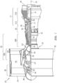
- FIG. 1 is a side cutaway illustration of a geared turbine engine 20.
- This turbine engine 20 extends along an axial centerline 22 between an upstream airflow inlet 24 and a downstream airflow exhaust 26.
- the turbine engine 20 includes a fan section 28, a compressor section 29, a combustor section 30 and a turbine section 31.
- the compressor section 29 includes a low pressure compressor (LPC) section 29A and a high pressure compressor (HPC) section 29B.
- the turbine section 31 includes a high pressure turbine (HPT) section 31A and a low pressure turbine (LPT) section 31B.
- the engine sections 28, 29A, 29B, 30, 31A and 31B are arranged sequentially along the centerline 22 within an engine housing 32.
- This housing 32 includes an inner case 34 (e.g., a core case) and an outer case 36 (e.g., a fan case).
- the inner case 34 may house one or more of the engine sections 29A-31B; e.g., an engine core.
- the outer case 36 may house at least the fan section 28.
- Each of the engine sections 28, 29A, 29B, 31A and 31B includes a respective rotor 38-42.
- Each of these rotors 38-42 includes a plurality of rotor blades arranged circumferentially around and connected to one or more respective rotor disks.
- the rotor blades may be formed integral with or mechanically fastened, welded, brazed, adhered and/or otherwise attached to the respective rotor disk(s).
- the fan rotor 38 is connected to a gear train 44, for example, through a fan shaft 46.
- the gear train 44 and the LPC rotor 39 are connected to and driven by the LPT rotor 42 through a low speed shaft 47.
- the HPC rotor 40 is connected to and driven by the HPT rotor 41 through a high speed shaft 48.
- the shafts 46-48 are rotatably supported by a plurality of bearings 50; e.g., rolling element and/or thrust bearings. Each of these bearings 50 is connected to the engine housing 32 by at least one stationary structure such as, for example, an annular support strut.
- the core gas path 52 extends sequentially through the engine sections 29A-31B.
- the air within the core gas path 52 may be referred to as "core air”.
- the bypass gas path 54 extends through a bypass duct, which bypasses the engine core.
- the air within the bypass gas path 54 may be referred to as "bypass air”.
- the core air is compressed by the compressor rotors 39 and 40 and directed into an annular combustion chamber 56 of a combustor 58 in the combustor section 30.
- Fuel is injected into the combustion chamber 56 and mixed with the compressed core air to provide a fuel-air mixture.
- This fuel air mixture is ignited and combustion products thereof flow through and sequentially cause the turbine rotors 41 and 42 to rotate.
- the rotation of the turbine rotors 41 and 42 respectively drive rotation of the compressor rotors 40 and 39 and, thus, compression of the air received from a core airflow inlet.
- the rotation of the turbine rotor 42 also drives rotation of the fan rotor 38, which propels bypass air through and out of the bypass gas path 54.
- the propulsion of the bypass air may account for a majority of thrust generated by the turbine engine 20, e.g., more than seventy-five percent (75%) of engine thrust.
- the turbine engine 20 of the present disclosure is not limited to the foregoing exemplary thrust ratio.
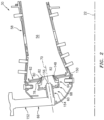
- the combustor section 30 includes a plurality of fuel injector assemblies 60 (one visible in FIG. 2 ) arranged circumferentially about the centerline 22 in an annular array.
- the fuel injector assemblies 60 are mounted to an annular bulkhead 62 of the combustor 58.
- the fuel injector assemblies 60 are configured to direct a mixture of fuel and compressed air into the combustion chamber 56 for combustion.
- Each fuel injector assembly 60 includes a high shear swirler 64 and a fuel injector 66.
- the fuel injector assembly 60 of FIG. 2 also includes a mount 68 configured to couple the fuel injector 66 to the swirler 64.
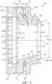
- the swirler 64 extends circumferentially around an axis 70 (e.g., a centerline of the swirler 64) thereby providing the swirler 64 with a full hoop body.
- the swirler 64 extends axially along the axis 70 between a swirler upstream end 72 and a swirler downstream end 74.
- the swirler 64 of FIG. 3 includes an upstream swirler segment 76, a flanged intermediate swirler segment 77 and a flanged downstream swirler segment 78. These swirler segments 76-78 configure the swirler 64 with a tubular swirler outer wall 80, a tubular swirler inner wall 82 (e.g., a fuel filmer) and a plurality of swirler passages 84 and 86.
- a tubular swirler outer wall 80 e.g., a fuel filmer
- swirler inner wall 82 e.g., a fuel filmer
- the upstream swirler segment 76 extends circumferentially around the axis 70.
- the upstream swirler segment 76 is located at (e.g., on, adjacent or proximate) the swirler upstream end 72.
- the upstream swirler segment 76 of FIG. 3 extends axially along the axis 70 from the swirler upstream end 72 to an annular upstream swirler segment surface 88.
- the upstream swirler segment 76 is configured with an upstream set of vanes 90. These upstream vanes 90 are arranged circumferentially around the axis 70 in an annular array. Each upstream vane 90 is circumferentially separated from each circumferentially adjacent (e.g., neighboring) upstream vane 90 by a respective air gap 92. The gaps 92 collectively form an upstream airflow inlet 94 into the swirler 64 at the swirler upstream end 72; see also FIG. 3 .
- the upstream vanes 90 may be configured such that air entering the swirler 64 through the upstream airflow inlet 94 generally flows in a first circumferential direction 96 (e.g., a clockwise direction) about the axis 70.
- the upstream vanes 90 may be configured such that air entering the swirler 64 through the upstream airflow inlet 94 generally flows in a second circumferential direction 98 (e.g., a counterclockwise direction) about the axis 70.
- a second circumferential direction 98 e.g., a counterclockwise direction
- each gap 92 may extend partially axially into the upstream swirler segment 76 from a castellated surface 100 of the segment 76 at the swirler upstream end 72 to a gap end surface 102.
- each gap 92 may be formed completely axially within the swirler 64 and, for example, its upstream swirler segment 76.
- the intermediate swirler segment 77 includes an annular intermediate swirler segment base 104 (e.g., a radial flange) and the swirler inner wall 82.
- the intermediate swirler segment 77 and each of its components 82 and 104 extends circumferentially around the axis 70.
- the intermediate swirler segment base 104 is abutted axially against the upstream swirler segment 76.
- the intermediate swirler segment base 104 may be coupled (e.g., bonded to) the upstream swirler segment surface 88.
- the intermediate swirler segment base 104 extends axially along the axis 70 from the upstream swirler segment 76 to an annular intermediate swirler segment surface 106.
- the intermediate swirler segment base 104 is configured with an intermediate set of vanes 108. These intermediate vanes 108 are arranged circumferentially around the axis 70 in an annular array. Each intermediate vane 108 is circumferentially separated from each circumferentially adjacent (e.g., neighboring) intermediate vane 108 by a respective gap 110. The gaps 110 collectively form an intermediate airflow inlet 112 into the swirler 64; see also FIG. 3 .
- the intermediate vanes 108 may be configured such that air entering the swirler 64 through the intermediate airflow inlet 112 generally flows in the first circumferential direction 96 (e.g., the clockwise direction) about the axis 70.
- first circumferential direction 96 e.g., the clockwise direction
- the intermediate vanes 108 may be configured such that air entering the swirler 64 through the intermediate airflow inlet 112 generally flows in the second circumferential direction 98 (e.g., the counterclockwise direction) about the axis 70.
- This circumferential direction for the intermediate vanes 108 may be the same as the circumferential direction for the upstream vanes 90. However, in other embodiments, the circumferential direction for the intermediate vanes 108 may be the opposite as the circumferential direction for the upstream vanes 90.
- each gap 110 may extend partially axially into the intermediate swirler segment 77 from a castellated surface 114 of the segment at the to a gap end surface 116.
- each gap may be formed completely axially within the swirler 64 and, for example, its intermediate swirler segment 77.
- the swirler inner wall 82 projects out from the intermediate swirler segment base 104 and extends axially (in a downstream direction along the axis 70) to an annular distal inner wall end 118. As the swirler inner wall 82 extends towards the distal inner wall end 118, the swirler inner wall 82 may (e.g., smoothly and/or continuously) radially taper inwards towards the axis 70. The swirler inner wall 82 may thereby have a tubular conical geometry with tubular conical inner and outer wall surfaces 120 and 122. The swirler inner wall 82 and its distal end 118 are each disposed radially with and axially overlapped by the swirler outer wall 80.
- the downstream swirler segment 78 includes an annular downstream swirler segment base 124 (e.g., a radial flange) and the swirler outer wall 80.
- the downstream swirler segment 78 and each of its components 80 and 124 extends circumferentially around the axis 70.
- the downstream swirler segment base 124 is abutted axially against the intermediate swirler segment 77.
- the downstream swirler segment base 124 may be coupled (e.g., bonded to) the intermediate swirler segment surface 106.
- the downstream swirler segment base 124 extends axially along the axis 70 from the intermediate swirler segment 77 to an annular downstream swirler segment surface 126.
- the downstream swirler segment base 124 is configured with a downstream set of vanes 128. These downstream vanes 128 are arranged circumferentially around the axis 70 in an annular array. Each downstream vane 128 is circumferentially separated from each circumferentially adjacent (e.g., neighboring) downstream vane 128 by a respective gap 130. The gaps 130 collectively form a downstream airflow inlet 132 into the swirler 64; see also FIG. 3 .
- the downstream vanes 128 may be configured such that air entering the swirler 64 through the downstream airflow inlet 132 generally flow in the first circumferential direction 96 (e.g., the clockwise direction) about the axis 70.
- first circumferential direction 96 e.g., the clockwise direction
- the downstream vanes 128 may be configured such that air entering the swirler 64 through the downstream airflow inlet 132 generally flows in the second circumferential direction 98 (e.g., the counterclockwise direction) about the axis 70.
- This circumferential direction for the downstream vanes 128 may be the same as the circumferential direction for the upstream vanes 90 and/or the intermediate vanes 108.
- the circumferential direction for the downstream vanes 128 may be the opposite as the circumferential direction for the upstream vanes 90 and/or the intermediate vanes 108.
- each gap 130 may extend partially axially into the downstream swirler segment 78 from a castellated surface 134 of the segment at the to a gap end surface 136.
- each gap 130 may be formed completely axially within the swirler 64 and, for example, its downstream swirler segment 78.
- the swirler outer wall 80 projects out from the downstream swirler segment base 124 and extends axially (in the downstream direction along the axis 70) to an annular distal outer wall end 138. As the swirler outer wall 80 extends towards the distal outer wall end 138, the swirler outer wall 80 may (e.g., smoothly and/or continuously) radially taper inwards towards the axis 70.
- the swirler outer wall 80 may thereby have a generally tubular conical geometry with a tubular conical inner wall surface 140.
- the swirler outer wall 80 axially overlaps and circumscribes the swirler outer wall 80.
- the swirler 64 is configured such that the distal inner wall end 118 and the distal outer wall end 138 are axially offset from one another along the axis 70.
- the distal inner wall end 118 of FIG. 3 for example, is axially recessed into the swirler 64 from the distal outer wall end 138. More particularly, the distal inner wall end 118 is disposed an axial distance (d) upstream of the distal outer wall end 138.
- the distal outer wall end 138 may thereby define a downstream most surface of the swirler 64; e.g., a dump plane of the swirler 64.
- the inner passage 84 of FIG. 3 is an inner bore of the swirler 64. This inner passage 84 is formed radially within and by each of the swirler segments 76 and 77. The inner passage 84 is fluidly coupled with the upstream airflow inlet 94 and the intermediate airflow inlet 112. The inner passage 84 of FIG. 3 extends from the airflow inlets 94 and 112 to an inner nozzle outlet 142. This inner nozzle outlet 142 is defined by and radially within the swirler inner wall 82 at the distal inner wall end 118.
- the outer passage 86 of FIG. 3 is an annular passage formed by the swirler segments 77 and 78. This outer passage 86 is formed radially between the swirler inner wall 82 and the swirler outer wall 80. The outer passage 86 is fluidly coupled with the downstream airflow inlet 132. The outer passage 86 of FIG. 3 extends from the downstream airflow inlet 132 to an outer nozzle outlet 144. This outer nozzle outlet 144 is defined by and radially between the swirler inner and outer walls 82 and 80 at their distal ends 118 and 138.
- the outer passage 86 and its nozzle outlet 144 are configured with an inner diameter (D sw-ex ) at the distal outer wall end 138.
- This diameter (D sw-ex ) is measured from, for example, the inner wall surface 140 of the swirler outer wall 80 on a corner between that surface 140 and an annular distal outer wall end surface 146.
- the swirler 64 is mated with the bulkhead 62.
- the swirler inner and outer walls 82 and 80 project axially into or through a respective aperture 148 in the bulkhead 62.
- the swirler 64 is mounted to the bulkhead 62.
- the downstream swirler segment 78 may be bonded (e.g., brazed or welded) and/or otherwise connected to the bulkhead 62 and, for example, a shell 150 of the bulkhead 62.
- the fuel injector 66 includes a fuel injector stem 152 and a fuel injector nozzle 154.
- the fuel injector stem 152 is configured to support and route fuel to the fuel injector nozzle 154.
- the fuel injector nozzle 154 is cantilevered from the fuel injector stem 152, and projects along the axis 70 partially into the inner bore of the swirler 64. A tip 156 of the fuel injector nozzle 154 is thereby disposed within the inner passage 84.
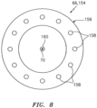
- the fuel injector nozzle 154 includes a plurality of nozzle orifices 158 arranged circumferentially about the axis 70 in an annular array; see also FIG. 8 .
- These nozzle orifices 158 may be axially aligned with (e.g., axially overlapped by) the swirler inner wall 82 and its inner wall surface 120.
- One or more or each of these nozzle orifices 158 is configured to direct a jet of fuel to impinge against the swirler inner wall 82 and its inner wall surface 120.
- the fuel injector nozzle 154 also includes a central nozzle orifice 160; see also FIG. 8 .
- This central nozzle orifice 160 is coaxial with the axis 70 and thereby centrally located between the nozzle orifices 158.
- the central nozzle orifice 160 is configured to direct a jet of fuel along the axis 70, through the inner nozzle outlet 142, and into the combustion chamber 56.
- a quantity of fuel provided by this central nozzle orifice 160 may be less than a collective quantity of fuel provided by the nozzle orifices 158; however, the present disclosure is not limited to such a relationship.
- the mount 68 is configured to couple the fuel injector nozzle 154 to the swirler 64.
- the mount 68 of FIG. 7 for example, includes a mount base 162 and a nozzle guide plate 164.
- the mount base 162 is connected (e.g., bonded) to the upstream swirler segment 76 and, for example, to its castellated surface 100.
- the mount base 162 is configured to capture the nozzle guide plate 164 in such a fashion that the nozzle guide plate 164 may float, to a limited degree, relative to the swirler 64.
- the nozzle guide plate 164 in turn is mated with the fuel injector nozzle 154.
- the fuel injector nozzle 154 for example, projects through a bore in the nozzle guide plate 164.
- the bore is sized such that the fuel injector nozzle 154 may slide axially along the axis 70 relative to the nozzle guide plate 164.
- the mount 68 thereby may (e.g., loosely) couple and locate the fuel injector nozzle 154 to the swirler while enabling for slight shifts due to differential thermal expansion as well as vibrations.
- the nozzle orifices 158 direct the jets of fuel to impinge against the swirler inner wall 82.
- the swirling air introduced into the inner passage 84 form the airflow inlets 94 and 112 (see FIG. 3 ) may cause the fuel from the jets to form a thin film of fuel on the inner wall surface 120.
- This film of fuel travels along the inner wall surface 120 towards the inner nozzle outlet 142.
- the film of fuel separates from the swirler inner wall 82 and is acted upon by swirling air exiting both the inner nozzle outlet 142 and the outer nozzle outlet 144.
- the air may exit the nozzle outlets 142 and 144 at different speeds and thereby subject the separated fuel to a shear force. This shear force may cause the separated fuel to break up and atomize for combustion within the combustion chamber 56.
- Atomization quality may depend upon a thickness of the film of fuel as well as a velocity and swirl of the air from the inner and the outer passages 84 and 86.
- the thickness of the film of fuel may depend upon an amount of fuel injected by the nozzle orifices 158 onto the swirler inner wall 82 and a length of travel along the swirler inner wall 82. Therefore, in general, decreasing the length of travel of the film of fuel along the swirler inner wall 82 may result in a thinner film thickness.
- the distal inner wall end 118 is positioned forward of the distal outer wall end 138 as described above.
- the fuel injector assembly 60 of the present disclosure may be operable to facilitate improved fuel and air mixing and/or a reduction in combustion dynamics.
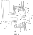
- the tip 156 of the fuel injector nozzle 154 is disposed an axial distance (D) along the axis 70 from the distal outer wall end 138.
- D axial distance
- the fuel injector assembly 60 may be configured such that the equation (D - d) / D sw-ex is less than or equal to one (e.g., less than 0.80) and/or greater than or equal to 0.25 (e.g., greater than 0.30).
- the fuel injector assembly 60 for example, may be configured such that the equation (D - d) / D sw-ex is between 0.35 and 0.68.
- the fuel injector assembly 60 is configured such that the equation D / D sw-ex is between 0.50 and 0.75.
- the fuel injector assembly 60 may be configured such that the equation d / D sw-ex is less than or equal to 0.20 and/or greater than or equal to 0.05.
- the fuel injector assembly 60 for example, may be configured such that the equation d / D sw-ex is between 0.07 and 0.15.
- each segment 76-78 may be discretely formed and subsequently connected (e.g., bonded and/or mechanically fastened) to the other segment(s).
- the swirler 64 may be configured such that any two or all of the segments 76-78 are formed integrally together as a unitary, monolithic body via, for example, casting and/or additive manufacturing.
- the swirler 64 may be configured with two airflow inlets.
- the swirler 64 for example, may be configured without the upstream swirler segment 76.
- the swirler 64 may be configured with more than three airflow inlets.
- the fuel injector assembly 60 may be included in various turbine engines other than the one described above as well as in other types of fuel powered equipment.
- the fuel injector assembly 60 may be included in a geared turbine engine where a gear train connects one or more shafts to one or more rotors in a fan section, a compressor section and/or any other engine section.
- the fuel injector assembly 60 may be included in a turbine engine configured without a gear train.
- the fuel injector assembly 60 may be included in a geared or non-geared turbine engine configured with a single spool, with two spools (e.g., see FIG. 1 ), or with more than two spools.
- the turbine engine may be configured as a turbofan engine, a turbojet engine, a propfan engine, a pusher fan engine or any other type of turbine engine. The present disclosure therefore is not limited to any particular types or configurations of turbine engines or equipment.
Landscapes
- Engineering & Computer Science (AREA)
- Chemical & Material Sciences (AREA)
- Combustion & Propulsion (AREA)
- Mechanical Engineering (AREA)
- General Engineering & Computer Science (AREA)
- Fuel-Injection Apparatus (AREA)
- Turbine Rotor Nozzle Sealing (AREA)
Claims (13)
- Anordnung (60) für ein Turbinentriebwerk (20), umfassend:einen Verwirbler (64), der mit einer Außenwand (80), einer Innenwand (82), einem äußeren Durchgang (86) und einem inneren Durchgang (84) konfiguriert ist, wobei die Außenwand (80) die Innenwand (82) umschreibt und sich axial entlang einer Achse (70) zu einem distalen Außenwandende (138) erstreckt, wobei sich die Innenwand (72) axial entlang der Achse (70) zu einem distalen Innenwandende (118), das axial innerhalb des Verwirblers (64) von dem distalen Außenwandende (138) eingelassen ist, erstreckt, wobei der äußere Durchgang (86) durch die Innenwand (82) und die Außenwand (80) gebildet ist und radial zwischen diesen verläuft und der innere Durchgang (84) durch die Innenwand (82) gebildet ist und radial innerhalb dieser verläuft; undeine Kraftstoffdüse (154), die in den inneren Durchgang (84) hineinragt, wobei die Kraftstoffdüse (154) mit einer Vielzahl von Öffnungen (158) konfiguriert ist, die axial mit der Innenwand (82) ausgerichtet und in Umfangsrichtung um die Achse (70) angeordnet sind,wobei:das distale Außenwandende (138) in einem Abstand (D) entlang der Achse (70) von einer Spitze (156) der Kraftstoffdüse (154) angeordnet ist; undder äußere Durchgang (86) einen Durchmesser (Dsw-ex) an dem distalen Außenwandende (138) aufweist, dadurch gekennzeichnet, dass die Kraftstoffdüse (154) ferner mit einer zweiten Öffnung (160) konfiguriert ist, die koaxial zu der Achse (70) ist und sich dadurch zentral zwischen den Öffnungen (158) befindet; und ein Quotient des Abstands (D) dividiert durch den Durchmesser (Dsw-ex) zwischen 0,5 und 0,75 beträgt.
- Anordnung (60) nach Anspruch 1, wobei die Vielzahl von Öffnungen (158) eine erste Öffnung (158) umfasst, die dazu konfiguriert ist, einen Kraftstoffstrahl so zu richten, dass er gegen die Innenwand (82) trifft.
- Anordnung (60) nach Anspruch 1 oder 2, wobeider Verwirbler (64) einen ersten Satz Schaufeln (128) und einen zweiten Satz Schaufeln (90) umfasst;der erste Satz Schaufeln (128) innerhalb des äußeren Durchgangs (86) angeordnet ist; undder zweite Satz Schaufeln (90) innerhalb des inneren Durchgangs (84) angeordnet ist.
- Anordnung (60) nach Anspruch 3, wobei:der Verwirbler (64) ferner einen dritten Satz Schaufeln (108) beinhaltet, der innerhalb des inneren Durchgangs (84) angeordnet ist; undder dritte Satz Schaufeln (108) axial versetzt zum zweiten Satz Schaufeln (90) ist.
- Anordnung (60) nach einem der vorhergehenden Ansprüche, ferner umfassend eine Düsenleitplatte (164), die die Kraftstoffdüse (154) an dem Verwirbler (64) befestigt.
- Anordnung (60) nach einem der vorhergehenden Ansprüche, wobei:die Anordnung eine Kraftstoffeinspritzanordnung (60) ist;
unddie Kraftstoffdüse (154) dazu konfiguriert ist, eine Vielzahl von Kraftstoffstrahlen gegen die Innenwand (82) zu richten. - Anordnung (60) nach Anspruch 6, wobei sich das distale Innenwandende (118) axial zwischen dem distalen Außenwandende (138) und einer Spitze (156) der Kraftstoffdüse (154) entlang der Achse (70) befindet.
- Anordnung (60) nach einem der vorhergehenden Ansprüche, wobei:der Abstand (D), entlang dem das distale Außenwandende (138) entlang der Achse (70) von der Spitze (156) der Kraftstoffdüse (154) angeordnet ist, ein erster Abstand (D) ist;das distale Außenwandende (138) in einem zweiten Abstand (d) entlang der Achse (70) vom distalen Innenwandende (118) angeordnet ist; undein Quotient aus (dem ersten Abstand (D) minus dem zweitem Abstand (d)) dividiert durch den Durchmesser (Dsw-ex) kleiner als eins ist.
- Anordnung (60) nach Anspruch 8, wobei der Quotient aus (dem ersten Abstand (D) minus dem zweiten Abstand (d)) dividiert durch den Durchmesser (Dsw-ex) kleiner oder gleich 0,8 ist.
- Anordnung (60) nach Anspruch 8 oder 9, wobei der Quotient aus (dem ersten Abstand (D) minus dem zweitem Abstand (d)) dividiert durch den Durchmesser (Dsw-ex) größer oder gleich 0,25 ist.
- Anordnung (60) nach einem der Ansprüche 8 bis 10, wobei der Quotient aus (dem ersten Abstand (D) minus dem zweiten Abstand (d)) dividiert durch den Durchmesser (Dsw-ex) zwischen 0,35 und 0,68 beträgt.
- Anordnung (60) nach einem der vorhergehenden Ansprüche, wobei die zweite Öffnung (160) dazu konfiguriert ist, einen Kraftstoffstrahl entlang der Achse (70) durch einen inneren Düsenauslass (142) und in eine Brennkammer (56) zu richten.
- Anordnung (60) nach einem der vorhergehenden Ansprüche, wobei die Innenwand (82) eine rohrförmige konische Geometrie mit einer rohrförmigen konischen Innenwandfläche (120) und einer rohrförmigen konischen Außenwandfläche (122) aufweist.
Applications Claiming Priority (1)
| Application Number | Priority Date | Filing Date | Title |
|---|---|---|---|
| US16/705,547 US11378275B2 (en) | 2019-12-06 | 2019-12-06 | High shear swirler with recessed fuel filmer for a gas turbine engine |
Publications (2)
| Publication Number | Publication Date |
|---|---|
| EP3832207A1 EP3832207A1 (de) | 2021-06-09 |
| EP3832207B1 true EP3832207B1 (de) | 2024-04-10 |
Family
ID=73740291
Family Applications (1)
| Application Number | Title | Priority Date | Filing Date |
|---|---|---|---|
| EP20212215.6A Active EP3832207B1 (de) | 2019-12-06 | 2020-12-07 | Krafststoffdüsenanordnung |
Country Status (2)
| Country | Link |
|---|---|
| US (1) | US11378275B2 (de) |
| EP (1) | EP3832207B1 (de) |
Families Citing this family (9)
| Publication number | Priority date | Publication date | Assignee | Title |
|---|---|---|---|---|
| CN110657452B (zh) * | 2018-06-29 | 2020-10-27 | 中国航发商用航空发动机有限责任公司 | 低污染燃烧室及其燃烧控制方法 |
| EP4317784A1 (de) * | 2022-08-04 | 2024-02-07 | RTX Corporation | Drallerzeuger mit eingebautem brennstofffilmerzeuger und luftunterstützter brennstoffdüse |
| EP4411230A1 (de) * | 2023-01-31 | 2024-08-07 | RTX Corporation | Entlüftung für eine gasturbinenmotorkraftstoffeinspritzanordnung |
| US12442331B2 (en) | 2023-02-02 | 2025-10-14 | Pratt & Whitney Canada Corp. | High shear fuel distributor |
| US11873993B1 (en) | 2023-02-02 | 2024-01-16 | Pratt & Whitney Canada Corp. | Combustor for gas turbine engine with central fuel injection ports |
| US12007115B1 (en) | 2023-02-28 | 2024-06-11 | Rtx Corporation | High shear swirler for gas turbine engine |
| US20240302044A1 (en) * | 2023-03-06 | 2024-09-12 | Raytheon Technologies Corporation | Canted fuel injector assembly for a turbine engine |
| US20250035306A1 (en) * | 2023-07-25 | 2025-01-30 | Collins Engine Nozzles, Inc. | Flat spray fuel injectors |
| EP4671612A1 (de) * | 2024-06-28 | 2025-12-31 | RTX Corporation | Gestufter mischer mit mehreren vorfilmungsummantelungen für eine kraftstoffeinspritzdüse |
Family Cites Families (58)
| Publication number | Priority date | Publication date | Assignee | Title |
|---|---|---|---|---|
| US4070826A (en) | 1975-12-24 | 1978-01-31 | General Electric Company | Low pressure fuel injection system |
| JPS617809Y2 (de) | 1978-10-30 | 1986-03-10 | ||
| US4653278A (en) * | 1985-08-23 | 1987-03-31 | General Electric Company | Gas turbine engine carburetor |
| DE3642122C1 (de) * | 1986-12-10 | 1988-06-09 | Mtu Muenchen Gmbh | Brennstoffeinspritzvorrichtung |
| US4854127A (en) | 1988-01-14 | 1989-08-08 | General Electric Company | Bimodal swirler injector for a gas turbine combustor |
| DE4110507C2 (de) * | 1991-03-30 | 1994-04-07 | Mtu Muenchen Gmbh | Brenner für Gasturbinentriebwerke mit mindestens einer für die Zufuhr von Verbrennungsluft lastabhängig regulierbaren Dralleinrichtung |
| DE4228816C2 (de) * | 1992-08-29 | 1998-08-06 | Mtu Muenchen Gmbh | Brenner für Gasturbinentriebwerke |
| US5505045A (en) * | 1992-11-09 | 1996-04-09 | Fuel Systems Textron, Inc. | Fuel injector assembly with first and second fuel injectors and inner, outer, and intermediate air discharge chambers |
| GB2272756B (en) * | 1992-11-24 | 1995-05-31 | Rolls Royce Plc | Fuel injection apparatus |
| US5444982A (en) * | 1994-01-12 | 1995-08-29 | General Electric Company | Cyclonic prechamber with a centerbody |
| FR2752917B1 (fr) * | 1996-09-05 | 1998-10-02 | Snecma | Systeme d'injection a degre d'homogeneisation avancee |
| FR2753779B1 (fr) * | 1996-09-26 | 1998-10-16 | Systeme d'injection aerodynamique d'un melange air carburant | |
| US5966937A (en) * | 1997-10-09 | 1999-10-19 | United Technologies Corporation | Radial inlet swirler with twisted vanes for fuel injector |
| US5987889A (en) * | 1997-10-09 | 1999-11-23 | United Technologies Corporation | Fuel injector for producing outer shear layer flame for combustion |
| GB2337102A (en) | 1998-05-09 | 1999-11-10 | Europ Gas Turbines Ltd | Gas-turbine engine combustor |
| US6367262B1 (en) * | 2000-09-29 | 2002-04-09 | General Electric Company | Multiple annular swirler |
| FR2827367B1 (fr) * | 2001-07-16 | 2003-10-17 | Snecma Moteurs | Systeme d'injection aeromecanique a vrille primaire anti-retour |
| FR2832493B1 (fr) * | 2001-11-21 | 2004-07-09 | Snecma Moteurs | Systeme d'injection multi-etages d'un melange air/carburant dans une chambre de combustion de turbomachine |
| US6834505B2 (en) * | 2002-10-07 | 2004-12-28 | General Electric Company | Hybrid swirler |
| US7104066B2 (en) * | 2003-08-19 | 2006-09-12 | General Electric Company | Combuster swirler assembly |
| US7334410B2 (en) * | 2004-04-07 | 2008-02-26 | United Technologies Corporation | Swirler |
| GB2439097B (en) * | 2006-06-15 | 2008-10-29 | Rolls Royce Plc | Fuel injector |
| FR2918716B1 (fr) * | 2007-07-12 | 2014-02-28 | Snecma | Optimisation d'un film anti-coke dans un systeme d'injection |
| FR2925146B1 (fr) * | 2007-12-14 | 2009-12-25 | Snecma | Systeme d'injection d'un melange d'air et de carburant dans une chambre de combustion de turbomachine |
| JP4815513B2 (ja) * | 2009-07-06 | 2011-11-16 | 川崎重工業株式会社 | ガスタービン燃焼器 |
| FR2956897B1 (fr) * | 2010-02-26 | 2012-07-20 | Snecma | Systeme d'injection pour chambre de combustion de turbomachine, comprenant des moyens d'injection d'air ameliorant le melange air-carburant |
| DE102010019772A1 (de) * | 2010-05-07 | 2011-11-10 | Rolls-Royce Deutschland Ltd & Co Kg | Magervormischbrenner eines Gasturbinentriebwerks mit einem konzentrischen, ringförmigen Zentralkörper |
| US10317081B2 (en) | 2011-01-26 | 2019-06-11 | United Technologies Corporation | Fuel injector assembly |
| US8640463B2 (en) | 2011-06-28 | 2014-02-04 | United Technologies Corporation | Swirler for gas turbine engine fuel injector |
| GB201112434D0 (en) * | 2011-07-20 | 2011-08-31 | Rolls Royce Plc | A fuel injector |
| US10094352B2 (en) | 2012-02-16 | 2018-10-09 | Delavan Inc. | Swirl impingement prefilming |
| US9404656B2 (en) * | 2012-12-17 | 2016-08-02 | United Technologies Corporation | Oblong swirler assembly for combustors |
| US9376985B2 (en) * | 2012-12-17 | 2016-06-28 | United Technologies Corporation | Ovate swirler assembly for combustors |
| GB201303428D0 (en) * | 2013-02-27 | 2013-04-10 | Rolls Royce Plc | A vane structure and a method of manufacturing a vane structure |
| US9284933B2 (en) * | 2013-03-01 | 2016-03-15 | Delavan Inc | Fuel nozzle with discrete jet inner air swirler |
| EP2971685B1 (de) | 2013-03-15 | 2021-06-23 | Raytheon Technologies Corporation | Brennkammerabschnitt für einen gasturbinenmotor |
| GB201315008D0 (en) * | 2013-08-22 | 2013-10-02 | Rolls Royce Plc | Airblast fuel injector |
| EP3039345B1 (de) * | 2013-08-30 | 2019-11-13 | United Technologies Corporation | Zweibrennstoffdüse mit flüssigfilmzerstäubung für einen gasturbinenmotor |
| WO2015050986A1 (en) | 2013-10-04 | 2015-04-09 | United Technologies Corporation | Swirler for a turbine engine combustor |
| CN105829800B (zh) * | 2013-12-23 | 2019-04-26 | 通用电气公司 | 用于空气协助的燃料喷射的燃料喷嘴结构 |
| CA2933539C (en) * | 2013-12-23 | 2022-01-18 | General Electric Company | Fuel nozzle with flexible support structures |
| FR3031799B1 (fr) * | 2015-01-19 | 2017-02-17 | Snecma | Dispositif d'etancheite ameliore entre un systeme d'injection et un nez d'injecteur de carburant de turbomachine d'aeronef |
| US9791153B2 (en) * | 2015-02-27 | 2017-10-17 | United Technologies Corporation | Line replaceable fuel nozzle apparatus, system and method |
| US9897321B2 (en) * | 2015-03-31 | 2018-02-20 | Delavan Inc. | Fuel nozzles |
| US10385809B2 (en) * | 2015-03-31 | 2019-08-20 | Delavan Inc. | Fuel nozzles |
| US10393030B2 (en) | 2016-10-03 | 2019-08-27 | United Technologies Corporation | Pilot injector fuel shifting in an axial staged combustor for a gas turbine engine |
| DE102016222097A1 (de) * | 2016-11-10 | 2018-05-17 | Rolls-Royce Deutschland Ltd & Co Kg | Treibstoffdüse einer Gasturbine mit Drallerzeuger |
| US10344981B2 (en) * | 2016-12-16 | 2019-07-09 | Delavan Inc. | Staged dual fuel radial nozzle with radial liquid fuel distributor |
| US20180238548A1 (en) * | 2017-02-22 | 2018-08-23 | Delavan Inc | Passive purge injectors |
| US20180335214A1 (en) * | 2017-05-18 | 2018-11-22 | United Technologies Corporation | Fuel air mixer assembly for a gas turbine engine combustor |
| US10591163B2 (en) * | 2017-07-21 | 2020-03-17 | United Technologies Corporation | Swirler for combustor of gas turbine engine |
| US10954859B2 (en) | 2017-07-25 | 2021-03-23 | Raytheon Technologies Corporation | Low emissions combustor assembly for gas turbine engine |
| US20190056108A1 (en) | 2017-08-21 | 2019-02-21 | General Electric Company | Non-uniform mixer for combustion dynamics attenuation |
| DE102017217328A1 (de) * | 2017-09-28 | 2019-03-28 | Rolls-Royce Deutschland Ltd & Co Kg | Düse mit axialer Verlängerung für eine Brennkammer eines Triebwerks |
| GB2568981A (en) * | 2017-12-01 | 2019-06-05 | Rolls Royce Plc | Fuel spray nozzle |
| GB201803650D0 (en) * | 2018-03-07 | 2018-04-25 | Rolls Royce Plc | A lean burn fuel injector |
| FR3082284B1 (fr) * | 2018-06-07 | 2020-12-11 | Safran Aircraft Engines | Chambre de combustion pour une turbomachine |
| US11226101B2 (en) * | 2019-02-01 | 2022-01-18 | General Electric Company | Combustor swirler |
-
2019
- 2019-12-06 US US16/705,547 patent/US11378275B2/en active Active
-
2020
- 2020-12-07 EP EP20212215.6A patent/EP3832207B1/de active Active
Also Published As
| Publication number | Publication date |
|---|---|
| US20210172604A1 (en) | 2021-06-10 |
| EP3832207A1 (de) | 2021-06-09 |
| US11378275B2 (en) | 2022-07-05 |
Similar Documents
| Publication | Publication Date | Title |
|---|---|---|
| EP3832207B1 (de) | Krafststoffdüsenanordnung | |
| EP3018418B1 (de) | Brennkammer mit wandöffnungskörper mit kühlkreislauf | |
| US10502422B2 (en) | Cooling a quench aperture body of a combustor wall | |
| US11320146B2 (en) | Film cooling a combustor wall of a turbine engine | |
| US20180283689A1 (en) | Film starters in combustors of gas turbine engines | |
| EP3940295B1 (de) | Gasturbinenmotoranordnung mit ablenkvorrichtung für einen leitungseinlass in einem brennkammerplenum | |
| EP3772568B1 (de) | Einlasserweiterung für tangentiale on-board-einspritzdüsen | |
| EP4421388A1 (de) | Kraftstoffeinspritzanordnung für gasturbinenmotor | |
| EP4317784A1 (de) | Drallerzeuger mit eingebautem brennstofffilmerzeuger und luftunterstützter brennstoffdüse | |
| EP4425051B1 (de) | Kraftstoff-einspritzvorrichtung mit hochscherverwirbler für gasturbinenmotor | |
| US20160231000A1 (en) | Swirler for a turbine engine combustor | |
| US12454912B2 (en) | Supplemental thrust system for a gas turbine engine | |
| US12429216B2 (en) | Turbine engine fuel injector assembly with annular fuel outlet | |
| US20240159398A1 (en) | Fuel injector assembly for gas turbine engine | |
| EP4421389B1 (de) | Luftverwirblerstruktur für kraftstoffinjektor mit geneigter strömungsführungsfläche | |
| US20240255147A1 (en) | Air purge for gas turbine engine fuel injector assembly | |
| US20240302042A1 (en) | Turbine engine combustor wall with aperture deflector | |
| US20260049575A1 (en) | Supplemental thrust system for a gas turbine engine | |
| EP4428443A1 (de) | Geneigte kraftstoffeinspritzdüsenanordnung für einen turbinenmotor | |
| US12158123B1 (en) | Supplemental thrust system with rotating detonation combustor | |
| US12546469B1 (en) | Gas turbine engine fuel injector with multiple fuel circuits |
Legal Events
| Date | Code | Title | Description |
|---|---|---|---|
| PUAI | Public reference made under article 153(3) epc to a published international application that has entered the european phase |
Free format text: ORIGINAL CODE: 0009012 |
|
| STAA | Information on the status of an ep patent application or granted ep patent |
Free format text: STATUS: THE APPLICATION HAS BEEN PUBLISHED |
|
| AK | Designated contracting states |
Kind code of ref document: A1 Designated state(s): AL AT BE BG CH CY CZ DE DK EE ES FI FR GB GR HR HU IE IS IT LI LT LU LV MC MK MT NL NO PL PT RO RS SE SI SK SM TR |
|
| STAA | Information on the status of an ep patent application or granted ep patent |
Free format text: STATUS: REQUEST FOR EXAMINATION WAS MADE |
|
| 17P | Request for examination filed |
Effective date: 20211209 |
|
| RBV | Designated contracting states (corrected) |
Designated state(s): AL AT BE BG CH CY CZ DE DK EE ES FI FR GB GR HR HU IE IS IT LI LT LU LV MC MK MT NL NO PL PT RO RS SE SI SK SM TR |
|
| STAA | Information on the status of an ep patent application or granted ep patent |
Free format text: STATUS: EXAMINATION IS IN PROGRESS |
|
| 17Q | First examination report despatched |
Effective date: 20221121 |
|
| RAP3 | Party data changed (applicant data changed or rights of an application transferred) |
Owner name: RTX CORPORATION |
|
| GRAP | Despatch of communication of intention to grant a patent |
Free format text: ORIGINAL CODE: EPIDOSNIGR1 |
|
| STAA | Information on the status of an ep patent application or granted ep patent |
Free format text: STATUS: GRANT OF PATENT IS INTENDED |
|
| INTG | Intention to grant announced |
Effective date: 20231107 |
|
| GRAS | Grant fee paid |
Free format text: ORIGINAL CODE: EPIDOSNIGR3 |
|
| GRAA | (expected) grant |
Free format text: ORIGINAL CODE: 0009210 |
|
| STAA | Information on the status of an ep patent application or granted ep patent |
Free format text: STATUS: THE PATENT HAS BEEN GRANTED |
|
| AK | Designated contracting states |
Kind code of ref document: B1 Designated state(s): AL AT BE BG CH CY CZ DE DK EE ES FI FR GB GR HR HU IE IS IT LI LT LU LV MC MK MT NL NO PL PT RO RS SE SI SK SM TR |
|
| REG | Reference to a national code |
Ref country code: GB Ref legal event code: FG4D |
|
| REG | Reference to a national code |
Ref country code: CH Ref legal event code: EP |
|
| REG | Reference to a national code |
Ref country code: DE Ref legal event code: R096 Ref document number: 602020028676 Country of ref document: DE |
|
| REG | Reference to a national code |
Ref country code: IE Ref legal event code: FG4D |
|
| REG | Reference to a national code |
Ref country code: LT Ref legal event code: MG9D |
|
| REG | Reference to a national code |
Ref country code: NL Ref legal event code: MP Effective date: 20240410 |
|
| REG | Reference to a national code |
Ref country code: AT Ref legal event code: MK05 Ref document number: 1675248 Country of ref document: AT Kind code of ref document: T Effective date: 20240410 |
|
| PG25 | Lapsed in a contracting state [announced via postgrant information from national office to epo] |
Ref country code: NL Free format text: LAPSE BECAUSE OF FAILURE TO SUBMIT A TRANSLATION OF THE DESCRIPTION OR TO PAY THE FEE WITHIN THE PRESCRIBED TIME-LIMIT Effective date: 20240410 |
|
| PG25 | Lapsed in a contracting state [announced via postgrant information from national office to epo] |
Ref country code: NL Free format text: LAPSE BECAUSE OF FAILURE TO SUBMIT A TRANSLATION OF THE DESCRIPTION OR TO PAY THE FEE WITHIN THE PRESCRIBED TIME-LIMIT Effective date: 20240410 |
|
| PG25 | Lapsed in a contracting state [announced via postgrant information from national office to epo] |
Ref country code: IS Free format text: LAPSE BECAUSE OF FAILURE TO SUBMIT A TRANSLATION OF THE DESCRIPTION OR TO PAY THE FEE WITHIN THE PRESCRIBED TIME-LIMIT Effective date: 20240810 |
|
| PG25 | Lapsed in a contracting state [announced via postgrant information from national office to epo] |
Ref country code: BG Free format text: LAPSE BECAUSE OF FAILURE TO SUBMIT A TRANSLATION OF THE DESCRIPTION OR TO PAY THE FEE WITHIN THE PRESCRIBED TIME-LIMIT Effective date: 20240410 |
|
| PG25 | Lapsed in a contracting state [announced via postgrant information from national office to epo] |
Ref country code: FI Free format text: LAPSE BECAUSE OF FAILURE TO SUBMIT A TRANSLATION OF THE DESCRIPTION OR TO PAY THE FEE WITHIN THE PRESCRIBED TIME-LIMIT Effective date: 20240410 Ref country code: HR Free format text: LAPSE BECAUSE OF FAILURE TO SUBMIT A TRANSLATION OF THE DESCRIPTION OR TO PAY THE FEE WITHIN THE PRESCRIBED TIME-LIMIT Effective date: 20240410 |
|
| PG25 | Lapsed in a contracting state [announced via postgrant information from national office to epo] |
Ref country code: GR Free format text: LAPSE BECAUSE OF FAILURE TO SUBMIT A TRANSLATION OF THE DESCRIPTION OR TO PAY THE FEE WITHIN THE PRESCRIBED TIME-LIMIT Effective date: 20240711 |
|
| PG25 | Lapsed in a contracting state [announced via postgrant information from national office to epo] |
Ref country code: PT Free format text: LAPSE BECAUSE OF FAILURE TO SUBMIT A TRANSLATION OF THE DESCRIPTION OR TO PAY THE FEE WITHIN THE PRESCRIBED TIME-LIMIT Effective date: 20240812 |
|
| PG25 | Lapsed in a contracting state [announced via postgrant information from national office to epo] |
Ref country code: ES Free format text: LAPSE BECAUSE OF FAILURE TO SUBMIT A TRANSLATION OF THE DESCRIPTION OR TO PAY THE FEE WITHIN THE PRESCRIBED TIME-LIMIT Effective date: 20240410 |
|
| PG25 | Lapsed in a contracting state [announced via postgrant information from national office to epo] |
Ref country code: AT Free format text: LAPSE BECAUSE OF FAILURE TO SUBMIT A TRANSLATION OF THE DESCRIPTION OR TO PAY THE FEE WITHIN THE PRESCRIBED TIME-LIMIT Effective date: 20240410 |
|
| PG25 | Lapsed in a contracting state [announced via postgrant information from national office to epo] |
Ref country code: PL Free format text: LAPSE BECAUSE OF FAILURE TO SUBMIT A TRANSLATION OF THE DESCRIPTION OR TO PAY THE FEE WITHIN THE PRESCRIBED TIME-LIMIT Effective date: 20240410 |
|
| PG25 | Lapsed in a contracting state [announced via postgrant information from national office to epo] |
Ref country code: LV Free format text: LAPSE BECAUSE OF FAILURE TO SUBMIT A TRANSLATION OF THE DESCRIPTION OR TO PAY THE FEE WITHIN THE PRESCRIBED TIME-LIMIT Effective date: 20240410 |
|
| PG25 | Lapsed in a contracting state [announced via postgrant information from national office to epo] |
Ref country code: PT Free format text: LAPSE BECAUSE OF FAILURE TO SUBMIT A TRANSLATION OF THE DESCRIPTION OR TO PAY THE FEE WITHIN THE PRESCRIBED TIME-LIMIT Effective date: 20240812 Ref country code: PL Free format text: LAPSE BECAUSE OF FAILURE TO SUBMIT A TRANSLATION OF THE DESCRIPTION OR TO PAY THE FEE WITHIN THE PRESCRIBED TIME-LIMIT Effective date: 20240410 Ref country code: NO Free format text: LAPSE BECAUSE OF FAILURE TO SUBMIT A TRANSLATION OF THE DESCRIPTION OR TO PAY THE FEE WITHIN THE PRESCRIBED TIME-LIMIT Effective date: 20240710 Ref country code: LV Free format text: LAPSE BECAUSE OF FAILURE TO SUBMIT A TRANSLATION OF THE DESCRIPTION OR TO PAY THE FEE WITHIN THE PRESCRIBED TIME-LIMIT Effective date: 20240410 Ref country code: IS Free format text: LAPSE BECAUSE OF FAILURE TO SUBMIT A TRANSLATION OF THE DESCRIPTION OR TO PAY THE FEE WITHIN THE PRESCRIBED TIME-LIMIT Effective date: 20240810 Ref country code: HR Free format text: LAPSE BECAUSE OF FAILURE TO SUBMIT A TRANSLATION OF THE DESCRIPTION OR TO PAY THE FEE WITHIN THE PRESCRIBED TIME-LIMIT Effective date: 20240410 Ref country code: GR Free format text: LAPSE BECAUSE OF FAILURE TO SUBMIT A TRANSLATION OF THE DESCRIPTION OR TO PAY THE FEE WITHIN THE PRESCRIBED TIME-LIMIT Effective date: 20240711 Ref country code: FI Free format text: LAPSE BECAUSE OF FAILURE TO SUBMIT A TRANSLATION OF THE DESCRIPTION OR TO PAY THE FEE WITHIN THE PRESCRIBED TIME-LIMIT Effective date: 20240410 Ref country code: ES Free format text: LAPSE BECAUSE OF FAILURE TO SUBMIT A TRANSLATION OF THE DESCRIPTION OR TO PAY THE FEE WITHIN THE PRESCRIBED TIME-LIMIT Effective date: 20240410 Ref country code: BG Free format text: LAPSE BECAUSE OF FAILURE TO SUBMIT A TRANSLATION OF THE DESCRIPTION OR TO PAY THE FEE WITHIN THE PRESCRIBED TIME-LIMIT Effective date: 20240410 Ref country code: AT Free format text: LAPSE BECAUSE OF FAILURE TO SUBMIT A TRANSLATION OF THE DESCRIPTION OR TO PAY THE FEE WITHIN THE PRESCRIBED TIME-LIMIT Effective date: 20240410 Ref country code: RS Free format text: LAPSE BECAUSE OF FAILURE TO SUBMIT A TRANSLATION OF THE DESCRIPTION OR TO PAY THE FEE WITHIN THE PRESCRIBED TIME-LIMIT Effective date: 20240710 |
|
| REG | Reference to a national code |
Ref country code: DE Ref legal event code: R097 Ref document number: 602020028676 Country of ref document: DE |
|
| PG25 | Lapsed in a contracting state [announced via postgrant information from national office to epo] |
Ref country code: DK Free format text: LAPSE BECAUSE OF FAILURE TO SUBMIT A TRANSLATION OF THE DESCRIPTION OR TO PAY THE FEE WITHIN THE PRESCRIBED TIME-LIMIT Effective date: 20240410 |
|
| PG25 | Lapsed in a contracting state [announced via postgrant information from national office to epo] |
Ref country code: EE Free format text: LAPSE BECAUSE OF FAILURE TO SUBMIT A TRANSLATION OF THE DESCRIPTION OR TO PAY THE FEE WITHIN THE PRESCRIBED TIME-LIMIT Effective date: 20240410 |
|
| PG25 | Lapsed in a contracting state [announced via postgrant information from national office to epo] |
Ref country code: CZ Free format text: LAPSE BECAUSE OF FAILURE TO SUBMIT A TRANSLATION OF THE DESCRIPTION OR TO PAY THE FEE WITHIN THE PRESCRIBED TIME-LIMIT Effective date: 20240410 |
|
| PG25 | Lapsed in a contracting state [announced via postgrant information from national office to epo] |
Ref country code: RO Free format text: LAPSE BECAUSE OF FAILURE TO SUBMIT A TRANSLATION OF THE DESCRIPTION OR TO PAY THE FEE WITHIN THE PRESCRIBED TIME-LIMIT Effective date: 20240410 Ref country code: SK Free format text: LAPSE BECAUSE OF FAILURE TO SUBMIT A TRANSLATION OF THE DESCRIPTION OR TO PAY THE FEE WITHIN THE PRESCRIBED TIME-LIMIT Effective date: 20240410 |
|
| PG25 | Lapsed in a contracting state [announced via postgrant information from national office to epo] |
Ref country code: SM Free format text: LAPSE BECAUSE OF FAILURE TO SUBMIT A TRANSLATION OF THE DESCRIPTION OR TO PAY THE FEE WITHIN THE PRESCRIBED TIME-LIMIT Effective date: 20240410 |
|
| PG25 | Lapsed in a contracting state [announced via postgrant information from national office to epo] |
Ref country code: SM Free format text: LAPSE BECAUSE OF FAILURE TO SUBMIT A TRANSLATION OF THE DESCRIPTION OR TO PAY THE FEE WITHIN THE PRESCRIBED TIME-LIMIT Effective date: 20240410 Ref country code: SK Free format text: LAPSE BECAUSE OF FAILURE TO SUBMIT A TRANSLATION OF THE DESCRIPTION OR TO PAY THE FEE WITHIN THE PRESCRIBED TIME-LIMIT Effective date: 20240410 Ref country code: RO Free format text: LAPSE BECAUSE OF FAILURE TO SUBMIT A TRANSLATION OF THE DESCRIPTION OR TO PAY THE FEE WITHIN THE PRESCRIBED TIME-LIMIT Effective date: 20240410 Ref country code: EE Free format text: LAPSE BECAUSE OF FAILURE TO SUBMIT A TRANSLATION OF THE DESCRIPTION OR TO PAY THE FEE WITHIN THE PRESCRIBED TIME-LIMIT Effective date: 20240410 Ref country code: DK Free format text: LAPSE BECAUSE OF FAILURE TO SUBMIT A TRANSLATION OF THE DESCRIPTION OR TO PAY THE FEE WITHIN THE PRESCRIBED TIME-LIMIT Effective date: 20240410 Ref country code: CZ Free format text: LAPSE BECAUSE OF FAILURE TO SUBMIT A TRANSLATION OF THE DESCRIPTION OR TO PAY THE FEE WITHIN THE PRESCRIBED TIME-LIMIT Effective date: 20240410 |
|
| PG25 | Lapsed in a contracting state [announced via postgrant information from national office to epo] |
Ref country code: IT Free format text: LAPSE BECAUSE OF FAILURE TO SUBMIT A TRANSLATION OF THE DESCRIPTION OR TO PAY THE FEE WITHIN THE PRESCRIBED TIME-LIMIT Effective date: 20240410 |
|
| PLBE | No opposition filed within time limit |
Free format text: ORIGINAL CODE: 0009261 |
|
| STAA | Information on the status of an ep patent application or granted ep patent |
Free format text: STATUS: NO OPPOSITION FILED WITHIN TIME LIMIT |
|
| 26N | No opposition filed |
Effective date: 20250113 |
|
| PG25 | Lapsed in a contracting state [announced via postgrant information from national office to epo] |
Ref country code: SI Free format text: LAPSE BECAUSE OF FAILURE TO SUBMIT A TRANSLATION OF THE DESCRIPTION OR TO PAY THE FEE WITHIN THE PRESCRIBED TIME-LIMIT Effective date: 20240410 |
|
| PG25 | Lapsed in a contracting state [announced via postgrant information from national office to epo] |
Ref country code: MC Free format text: LAPSE BECAUSE OF FAILURE TO SUBMIT A TRANSLATION OF THE DESCRIPTION OR TO PAY THE FEE WITHIN THE PRESCRIBED TIME-LIMIT Effective date: 20240410 |
|
| REG | Reference to a national code |
Ref country code: CH Ref legal event code: PL |
|
| PG25 | Lapsed in a contracting state [announced via postgrant information from national office to epo] |
Ref country code: LU Free format text: LAPSE BECAUSE OF NON-PAYMENT OF DUE FEES Effective date: 20241207 |
|
| PG25 | Lapsed in a contracting state [announced via postgrant information from national office to epo] |
Ref country code: SE Free format text: LAPSE BECAUSE OF FAILURE TO SUBMIT A TRANSLATION OF THE DESCRIPTION OR TO PAY THE FEE WITHIN THE PRESCRIBED TIME-LIMIT Effective date: 20240410 |
|
| REG | Reference to a national code |
Ref country code: BE Ref legal event code: MM Effective date: 20241231 |
|
| PG25 | Lapsed in a contracting state [announced via postgrant information from national office to epo] |
Ref country code: BE Free format text: LAPSE BECAUSE OF NON-PAYMENT OF DUE FEES Effective date: 20241231 |
|
| PG25 | Lapsed in a contracting state [announced via postgrant information from national office to epo] |
Ref country code: CH Free format text: LAPSE BECAUSE OF NON-PAYMENT OF DUE FEES Effective date: 20241231 |
|
| PG25 | Lapsed in a contracting state [announced via postgrant information from national office to epo] |
Ref country code: IE Free format text: LAPSE BECAUSE OF NON-PAYMENT OF DUE FEES Effective date: 20241207 |
|
| PGFP | Annual fee paid to national office [announced via postgrant information from national office to epo] |
Ref country code: DE Payment date: 20251126 Year of fee payment: 6 |
|
| PGFP | Annual fee paid to national office [announced via postgrant information from national office to epo] |
Ref country code: GB Payment date: 20251119 Year of fee payment: 6 |
|
| PGFP | Annual fee paid to national office [announced via postgrant information from national office to epo] |
Ref country code: FR Payment date: 20251120 Year of fee payment: 6 |