EP3832120A1 - Engine air intake device - Google Patents
Engine air intake device Download PDFInfo
- Publication number
- EP3832120A1 EP3832120A1 EP19859563.9A EP19859563A EP3832120A1 EP 3832120 A1 EP3832120 A1 EP 3832120A1 EP 19859563 A EP19859563 A EP 19859563A EP 3832120 A1 EP3832120 A1 EP 3832120A1
- Authority
- EP
- European Patent Office
- Prior art keywords
- engine
- heat storage
- duct
- intake
- storage cover
- Prior art date
- Legal status (The legal status is an assumption and is not a legal conclusion. Google has not performed a legal analysis and makes no representation as to the accuracy of the status listed.)
- Granted
Links
- 238000005338 heat storage Methods 0.000 claims abstract description 78
- 238000002485 combustion reaction Methods 0.000 claims abstract description 52
- 230000017525 heat dissipation Effects 0.000 claims abstract description 16
- 230000000903 blocking effect Effects 0.000 claims abstract description 5
- 239000000498 cooling water Substances 0.000 claims description 11
- 238000009423 ventilation Methods 0.000 claims description 8
- 125000006850 spacer group Chemical group 0.000 description 18
- 230000001105 regulatory effect Effects 0.000 description 4
- 239000007789 gas Substances 0.000 description 3
- 230000001965 increasing effect Effects 0.000 description 3
- 230000002093 peripheral effect Effects 0.000 description 3
- 230000000630 rising effect Effects 0.000 description 3
- 238000011144 upstream manufacturing Methods 0.000 description 3
- 230000007257 malfunction Effects 0.000 description 2
- 238000005192 partition Methods 0.000 description 2
- 229920003002 synthetic resin Polymers 0.000 description 2
- 239000000057 synthetic resin Substances 0.000 description 2
- 239000002918 waste heat Substances 0.000 description 2
- 238000003466 welding Methods 0.000 description 2
- 238000013459 approach Methods 0.000 description 1
- 239000002131 composite material Substances 0.000 description 1
- 230000008878 coupling Effects 0.000 description 1
- 238000010168 coupling process Methods 0.000 description 1
- 238000005859 coupling reaction Methods 0.000 description 1
- 230000003247 decreasing effect Effects 0.000 description 1
- 230000002542 deteriorative effect Effects 0.000 description 1
- 239000000428 dust Substances 0.000 description 1
- 230000000694 effects Effects 0.000 description 1
- 230000002708 enhancing effect Effects 0.000 description 1
- 239000000446 fuel Substances 0.000 description 1
- 238000012423 maintenance Methods 0.000 description 1
- 230000013011 mating Effects 0.000 description 1
- 238000000034 method Methods 0.000 description 1
- 230000002265 prevention Effects 0.000 description 1
- 238000004904 shortening Methods 0.000 description 1
- XLYOFNOQVPJJNP-UHFFFAOYSA-N water Substances O XLYOFNOQVPJJNP-UHFFFAOYSA-N 0.000 description 1
Images


Classifications
-
- F—MECHANICAL ENGINEERING; LIGHTING; HEATING; WEAPONS; BLASTING
- F02—COMBUSTION ENGINES; HOT-GAS OR COMBUSTION-PRODUCT ENGINE PLANTS
- F02M—SUPPLYING COMBUSTION ENGINES IN GENERAL WITH COMBUSTIBLE MIXTURES OR CONSTITUENTS THEREOF
- F02M35/00—Combustion-air cleaners, air intakes, intake silencers, or induction systems specially adapted for, or arranged on, internal-combustion engines
- F02M35/10—Air intakes; Induction systems
-
- B—PERFORMING OPERATIONS; TRANSPORTING
- B60—VEHICLES IN GENERAL
- B60K—ARRANGEMENT OR MOUNTING OF PROPULSION UNITS OR OF TRANSMISSIONS IN VEHICLES; ARRANGEMENT OR MOUNTING OF PLURAL DIVERSE PRIME-MOVERS IN VEHICLES; AUXILIARY DRIVES FOR VEHICLES; INSTRUMENTATION OR DASHBOARDS FOR VEHICLES; ARRANGEMENTS IN CONNECTION WITH COOLING, AIR INTAKE, GAS EXHAUST OR FUEL SUPPLY OF PROPULSION UNITS IN VEHICLES
- B60K11/00—Arrangement in connection with cooling of propulsion units
- B60K11/08—Air inlets for cooling; Shutters or blinds therefor
-
- B—PERFORMING OPERATIONS; TRANSPORTING
- B60—VEHICLES IN GENERAL
- B60K—ARRANGEMENT OR MOUNTING OF PROPULSION UNITS OR OF TRANSMISSIONS IN VEHICLES; ARRANGEMENT OR MOUNTING OF PLURAL DIVERSE PRIME-MOVERS IN VEHICLES; AUXILIARY DRIVES FOR VEHICLES; INSTRUMENTATION OR DASHBOARDS FOR VEHICLES; ARRANGEMENTS IN CONNECTION WITH COOLING, AIR INTAKE, GAS EXHAUST OR FUEL SUPPLY OF PROPULSION UNITS IN VEHICLES
- B60K13/00—Arrangement in connection with combustion air intake or gas exhaust of propulsion units
- B60K13/02—Arrangement in connection with combustion air intake or gas exhaust of propulsion units concerning intake
-
- F—MECHANICAL ENGINEERING; LIGHTING; HEATING; WEAPONS; BLASTING
- F01—MACHINES OR ENGINES IN GENERAL; ENGINE PLANTS IN GENERAL; STEAM ENGINES
- F01P—COOLING OF MACHINES OR ENGINES IN GENERAL; COOLING OF INTERNAL-COMBUSTION ENGINES
- F01P11/00—Component parts, details, or accessories not provided for in, or of interest apart from, groups F01P1/00 - F01P9/00
- F01P11/10—Guiding or ducting cooling-air, to, or from, liquid-to-air heat exchangers
-
- F—MECHANICAL ENGINEERING; LIGHTING; HEATING; WEAPONS; BLASTING
- F01—MACHINES OR ENGINES IN GENERAL; ENGINE PLANTS IN GENERAL; STEAM ENGINES
- F01P—COOLING OF MACHINES OR ENGINES IN GENERAL; COOLING OF INTERNAL-COMBUSTION ENGINES
- F01P3/00—Liquid cooling
- F01P3/18—Arrangements or mounting of liquid-to-air heat-exchangers
-
- F—MECHANICAL ENGINEERING; LIGHTING; HEATING; WEAPONS; BLASTING
- F02—COMBUSTION ENGINES; HOT-GAS OR COMBUSTION-PRODUCT ENGINE PLANTS
- F02B—INTERNAL-COMBUSTION PISTON ENGINES; COMBUSTION ENGINES IN GENERAL
- F02B77/00—Component parts, details or accessories, not otherwise provided for
- F02B77/11—Thermal or acoustic insulation
- F02B77/13—Acoustic insulation
-
- F—MECHANICAL ENGINEERING; LIGHTING; HEATING; WEAPONS; BLASTING
- F02—COMBUSTION ENGINES; HOT-GAS OR COMBUSTION-PRODUCT ENGINE PLANTS
- F02M—SUPPLYING COMBUSTION ENGINES IN GENERAL WITH COMBUSTIBLE MIXTURES OR CONSTITUENTS THEREOF
- F02M31/00—Apparatus for thermally treating combustion-air, fuel, or fuel-air mixture
- F02M31/02—Apparatus for thermally treating combustion-air, fuel, or fuel-air mixture for heating
- F02M31/04—Apparatus for thermally treating combustion-air, fuel, or fuel-air mixture for heating combustion-air or fuel-air mixture
- F02M31/042—Combustion air
-
- F—MECHANICAL ENGINEERING; LIGHTING; HEATING; WEAPONS; BLASTING
- F02—COMBUSTION ENGINES; HOT-GAS OR COMBUSTION-PRODUCT ENGINE PLANTS
- F02M—SUPPLYING COMBUSTION ENGINES IN GENERAL WITH COMBUSTIBLE MIXTURES OR CONSTITUENTS THEREOF
- F02M31/00—Apparatus for thermally treating combustion-air, fuel, or fuel-air mixture
- F02M31/02—Apparatus for thermally treating combustion-air, fuel, or fuel-air mixture for heating
- F02M31/04—Apparatus for thermally treating combustion-air, fuel, or fuel-air mixture for heating combustion-air or fuel-air mixture
- F02M31/06—Apparatus for thermally treating combustion-air, fuel, or fuel-air mixture for heating combustion-air or fuel-air mixture by hot gases, e.g. by mixing cold and hot air
-
- F—MECHANICAL ENGINEERING; LIGHTING; HEATING; WEAPONS; BLASTING
- F02—COMBUSTION ENGINES; HOT-GAS OR COMBUSTION-PRODUCT ENGINE PLANTS
- F02M—SUPPLYING COMBUSTION ENGINES IN GENERAL WITH COMBUSTIBLE MIXTURES OR CONSTITUENTS THEREOF
- F02M31/00—Apparatus for thermally treating combustion-air, fuel, or fuel-air mixture
- F02M31/02—Apparatus for thermally treating combustion-air, fuel, or fuel-air mixture for heating
- F02M31/14—Apparatus for thermally treating combustion-air, fuel, or fuel-air mixture for heating by using heat from working cylinders or cylinder heads
- F02M31/145—Apparatus for thermally treating combustion-air, fuel, or fuel-air mixture for heating by using heat from working cylinders or cylinder heads with particular constructional means
-
- F—MECHANICAL ENGINEERING; LIGHTING; HEATING; WEAPONS; BLASTING
- F02—COMBUSTION ENGINES; HOT-GAS OR COMBUSTION-PRODUCT ENGINE PLANTS
- F02M—SUPPLYING COMBUSTION ENGINES IN GENERAL WITH COMBUSTIBLE MIXTURES OR CONSTITUENTS THEREOF
- F02M35/00—Combustion-air cleaners, air intakes, intake silencers, or induction systems specially adapted for, or arranged on, internal-combustion engines
- F02M35/10—Air intakes; Induction systems
- F02M35/10006—Air intakes; Induction systems characterised by the position of elements of the air intake system in direction of the air intake flow, i.e. between ambient air inlet and supply to the combustion chamber
- F02M35/10013—Means upstream of the air filter; Connection to the ambient air
-
- F—MECHANICAL ENGINEERING; LIGHTING; HEATING; WEAPONS; BLASTING
- F02—COMBUSTION ENGINES; HOT-GAS OR COMBUSTION-PRODUCT ENGINE PLANTS
- F02M—SUPPLYING COMBUSTION ENGINES IN GENERAL WITH COMBUSTIBLE MIXTURES OR CONSTITUENTS THEREOF
- F02M35/00—Combustion-air cleaners, air intakes, intake silencers, or induction systems specially adapted for, or arranged on, internal-combustion engines
- F02M35/10—Air intakes; Induction systems
- F02M35/10091—Air intakes; Induction systems characterised by details of intake ducts: shapes; connections; arrangements
-
- F—MECHANICAL ENGINEERING; LIGHTING; HEATING; WEAPONS; BLASTING
- F02—COMBUSTION ENGINES; HOT-GAS OR COMBUSTION-PRODUCT ENGINE PLANTS
- F02M—SUPPLYING COMBUSTION ENGINES IN GENERAL WITH COMBUSTIBLE MIXTURES OR CONSTITUENTS THEREOF
- F02M35/00—Combustion-air cleaners, air intakes, intake silencers, or induction systems specially adapted for, or arranged on, internal-combustion engines
- F02M35/10—Air intakes; Induction systems
- F02M35/10242—Devices or means connected to or integrated into air intakes; Air intakes combined with other engine or vehicle parts
- F02M35/10288—Air intakes combined with another engine part, e.g. cylinder head cover or being cast in one piece with the exhaust manifold, cylinder head or engine block
-
- F—MECHANICAL ENGINEERING; LIGHTING; HEATING; WEAPONS; BLASTING
- F02—COMBUSTION ENGINES; HOT-GAS OR COMBUSTION-PRODUCT ENGINE PLANTS
- F02M—SUPPLYING COMBUSTION ENGINES IN GENERAL WITH COMBUSTIBLE MIXTURES OR CONSTITUENTS THEREOF
- F02M35/00—Combustion-air cleaners, air intakes, intake silencers, or induction systems specially adapted for, or arranged on, internal-combustion engines
- F02M35/16—Combustion-air cleaners, air intakes, intake silencers, or induction systems specially adapted for, or arranged on, internal-combustion engines characterised by use in vehicles
- F02M35/161—Arrangement of the air intake system in the engine compartment, e.g. with respect to the bonnet or the vehicle front face
-
- F—MECHANICAL ENGINEERING; LIGHTING; HEATING; WEAPONS; BLASTING
- F01—MACHINES OR ENGINES IN GENERAL; ENGINE PLANTS IN GENERAL; STEAM ENGINES
- F01P—COOLING OF MACHINES OR ENGINES IN GENERAL; COOLING OF INTERNAL-COMBUSTION ENGINES
- F01P1/00—Air cooling
- F01P2001/005—Cooling engine rooms
-
- Y—GENERAL TAGGING OF NEW TECHNOLOGICAL DEVELOPMENTS; GENERAL TAGGING OF CROSS-SECTIONAL TECHNOLOGIES SPANNING OVER SEVERAL SECTIONS OF THE IPC; TECHNICAL SUBJECTS COVERED BY FORMER USPC CROSS-REFERENCE ART COLLECTIONS [XRACs] AND DIGESTS
- Y02—TECHNOLOGIES OR APPLICATIONS FOR MITIGATION OR ADAPTATION AGAINST CLIMATE CHANGE
- Y02T—CLIMATE CHANGE MITIGATION TECHNOLOGIES RELATED TO TRANSPORTATION
- Y02T10/00—Road transport of goods or passengers
- Y02T10/10—Internal combustion engine [ICE] based vehicles
- Y02T10/12—Improving ICE efficiencies
Definitions
- the present invention relates to an intake device for an engine.
- Patent Literature 1 discloses providing, in an engine room, a cylinder head-side thermal insulating cover composed of an upper wall covering a top face of an engine and a side wall covering both side faces of an upper portion of the engine in the vehicle width direction.
- the vehicle front side of the thermal insulating cover is supported on an upper end of a radiator shroud, and the vehicle rear side thereof is supported on a dash panel.
- Patent Literature 1 also discloses providing a cylinder block-side thermal insulating cover covering a face on the vehicle front side of a cylinder block, a face on the vehicle rear side of the cylinder block, both side faces of the cylinder block in the vehicle width direction, and substantially the whole of an oil pan.
- Patent Literature 1 Japanese Patent Laid-Open No. 2017-180210
- the present invention suppresses a decrease in temperature of a combustion chamber of an engine due to fresh air introduction into the combustion chamber.
- the present invention enables to introduce high temperature air into a combustion chamber by using heat dissipated from an engine.
- An intake device for an engine disclosed herein includes an intake passage for introducing air in an engine room into a combustion chamber of the engine, and a heat storage cover provided in the engine room, the heat storage cover covering the engine from above and at least partially surrounding the periphery of the engine to internally store, through the medium of air, heat dissipated from the engine and block at least a part of upward heat dissipation, and is characterized in that the intake passage includes an air inlet for introducing, into the combustion chamber, high temperature air obtained by the heat storage cover blocking the upward heat dissipation.
- the upward heat dissipation is blocked by the heat storage cover, so that the temperature of air not only inside the heat storage cover but also below a lower edge of this heat storage cover becomes high. Accordingly, even when the air inlet of the intake passage is disposed below the heat storage cover, the high temperature air can be introduced into the combustion chamber.
- the air inlet of the intake passage faces the inside of the heat storage cover.
- the high temperature air inside the heat storage cover can be reliably introduced into the combustion chamber.
- the inside of the heat storage cover refers to the lower side of, in the heat storage cover, an inner face of a portion covering the engine from above, and the inside of, in the heat storage cover, an inner face of a portion at least partially surrounding the periphery of the engine.
- the engine room includes a radiator that dissipates heat of cooling water of the engine toward the engine, and the air inlet of the intake passage is disposed between the engine and the radiator.
- the radiator serves to prevent the heat dissipation from the engine, and waste heat released from the radiator (heat taken from the cooling water by heat exchange) is supplied to the engine side.
- waste heat released from the radiator heat taken from the cooling water by heat exchange
- the temperature of air between the engine and the radiator becomes high.
- This high temperature air between the engine and the radiator is brought into the intake passage and introduced into the combustion chamber, so that it is further advantageous in securing the combustion stability of the engine.
- the engine room is provided in a front portion of a vehicle, the engine is a front intake and rear exhaust engine,
- the air inlet is disposed between this engine and the radiator, so that it is advantageous in introducing the high temperature air into the combustion chamber of the engine.
- the air inlet is disposed on the front side of the engine, so that the intake passage from the air inlet to the combustion chamber of the engine does not become long, which is advantageous in introducing the high temperature air into the combustion chamber and also facilitates the layout of the intake passage.
- a shutter that, when the high temperature air obtained by the heat storage cover is introduced into the combustion chamber, blocks ventilation to the radiator.
- the ventilation to the radiator is blocked by the shutter, so that a thermal insulating property on the radiator side of the engine is increased, which is advantageous in introducing the high temperature air into the combustion chamber.
- the heat storage cover covering the engine from above and at least partially surrounding the periphery of the engine is provided in the engine room, and the high temperature air obtained by this heat storage cover blocking the upward heat dissipation is introduced into the combustion chamber of the engine, so that, for example, even when a large amount of air is required as in a lean combustion, a decrease in temperature of the combustion chamber is suppressed, which is advantageous in securing the combustion stability of the engine.
- FIG. 1 illustrates an inside of an engine room 1 including an intake device for an engine according to the present embodiment.
- the engine room 1 is provided as a recess open on the upper side in a vehicle front portion and accommodates an engine 2 and peripherals of the engine 2.
- the opening on the upper side of the engine room 1 is blocked by a bonnet 3.
- the bonnet 2 is openable and closable, so that the inside of the engine room 1 can be seen from the outside of a vehicle by opening the bonnet 3 as necessary.
- the inside of the engine room 1 refers to a space defined when the opening on the upper side of the engine room 1 is blocked by closing the bonnet 3.
- the advancing-receding direction of the vehicle is referred to as “the front-rear direction”
- the advancing side is referred to as “the front side”
- the receding side is referred to as “the rear side.”
- the vehicle width direction is referred to as "the left-right direction.”
- “the right side” and “the left side” are when the vehicle is viewed from the front side.
- the engine 2 includes a cylinder block 4 and a cylinder head placed on the cylinder block 4.
- An oil pan 5 is fixed to a bottom face of the cylinder block 4.
- a plurality of cylinders are formed inside the cylinder block 4. That is, the engine 2 is a multi-cylinder engine.
- a piston is slidably inserted into each cylinder.
- the piston is connected to a crankshaft via a connecting rod.
- the piston defines a combustion chamber of the engine 2 together with the cylinder and the cylinder head.
- Fresh air is introduced into the combustion chamber of the engine 2 through an intake duct 11 and an air cleaner 12.
- the air cleaner 12 is a device that removes foreign matter such as dust or dirt contained in the fresh air to be introduced into the combustion chamber.
- FIG. 2 is a view of the engine 2 as viewed from the top, with a top face cover 22 of a heat storage cover 21, which will be described later, being removed.
- the fresh air passes through an intake pipe 13 including a throttle valve from the air cleaner 12 and is introduced into a supercharger 14.
- the supercharger 14 increases the pressure of the fresh air to be introduced into the combustion chamber.
- the supercharger 14 of the present example is a mechanical supercharger that is driven via a belt by the crankshaft of the engine 2. Note that an electric supercharger or a turbosupercharger that is driven by exhaust energy may be adopted.
- the fresh air passing through the supercharger 14 is cooled by an intercooler 15 illustrated in FIG. 3 and is introduced into the combustion chamber of each cylinder via a surge tank and an intake manifold.
- a bypass pipe 16 bypassing the supercharger 14 and leading the fresh air to the surge tank branches from the intake pipe 13.
- the bypass pipe 16 is provided with a bypass valve that adjusts an opening area of a conduit of the bypass pipe 16.
- An EGR pipe 17 illustrated in FIG. 1 is connected to a section upstream of the bypass valve of the bypass pipe 16.
- the EGR pipe 17 returns, as EGR gas, a part of exhaust gas to the combustion chamber and includes an EGR cooler 18 that cools the EGR gas.
- the intake duct 11, the air cleaner 12, the intake pipe 13, the supercharger 14, the intercooler 15, the surge tank, and the intake manifold which form an air intake system of the engine 2 are disposed on the front side of the engine 2, and an exhaust manifold and an exhaust pipe continuing to the exhaust manifold which form an exhaust system of the engine 2 are disposed on the rear side of the engine 2. That is, the engine 2 is a front intake and rear exhaust engine.
- the heat storage cover 21 is provided in the engine room 1, covers the engine 2 from above the engine 2, and surrounds the periphery of an upper portion of the engine 2. Heat dissipated from the engine 2 is stored inside the heat storage cover 21 through the medium of air, and the heat storage cover 21 blocks at least a part of upward heat dissipation.
- the heat storage cover 21 includes, as illustrated in FIG. 1 , the top face cover portion 22 covering the engine 2 from above, a rear face cover portion 23 continuous to the top face cover portion 22 and covering the upper portion of the engine 2 from behind, and a right-side face cover portion 24 continuous to the top face cover portion 22 and covering the upper portion of the engine 2 from the right side, and further includes, as illustrated in FIG. 4 , a left-side face cover portion 25 continuous to the top face cover portion 22 and covering the upper portion of the engine 2 from the left side.
- a radiator 6 that cools cooling water of the engine 2 by heat exchange with air is disposed in front of the engine 2 so as to cover the engine 2 from the front side.
- a grille shutter 7 capable of blocking ventilation from the front side to the radiator 6 is provided in front of the radiator 6.
- the radiator 6 includes, on the back side, a radiator fan 8 that dissipates heat of the cooling water toward the engine 2.
- a front grille 9 is provided in front of the grille shutter 7.
- the grille shutter 7 has a plurality of flaps 26 disposed at intervals in the up-down direction and includes an actuator that pivots each of the plurality of flaps 26.
- the flaps 26 become horizontal as indicated by the chain line, ventilation from the front side to the radiator 6 is allowed, and when the flaps 26 become vertical as indicated by the solid line, the ventilation to the radiator 6 is blocked.
- a passage switching mechanism of the intake duct 11, which will be described later, is operated and introduction of the fresh air into the combustion chamber of the engine 2 is brought into an inside air introduction state, in the grille shutter 7, the flaps 26 become vertical, thereby suppressing hitting of vehicle traveling air against the radiator 6. As a result, heat dissipation from the engine room 1 to the front side is also suppressed.
- Cooling water inflow hoses 27 and 28 through which the cooling water from the engine 2 flows in, and a cooling water outflow hose (see FIGS. 1 and 2 ) 31 through which cooling water whose temperature has decreased is sent to a water pump 29 illustrated in FIG. 4 are connected to the radiator 6.
- the heat storage cover 21 blocks heat dissipation from the upper portion of the engine 2 to the upper side and the periphery, thereby contributing to keeping the engine 2 warm.
- the radiator 6 and the grille shutter 7 block heat dissipation from the engine 2 to the front side, thereby contributing to keeping the engine 2 warm.
- the radiator 6 emits the heat of the cooling water toward the engine 2 by using the radiator fan 8, thereby making heat storage of the heat storage cover 21 advantageous.
- the air cleaner 12 is disposed on the right outer side of the heat storage cover 21 as viewed from the vehicle front side.
- the intake duct 11 is disposed on the outside of the heat storage cover 21 and on the front side of the air cleaner 12.
- the top face cover portion 22 of the heat storage cover 21 includes an upper wall 22a gradually inclined downward toward the front side, and upper side walls 22b and 22c (see FIGS. 1 and 4 ) continuing to both side edges of the upper wall 22a and extending downward.
- the upper wall 22a spreads outward relative to a top face of the engine 2 so as to cover the whole of the top face of the engine 2.
- a front end portion of the upper wall 22a is provided with a fixed portion 22d for fixing the heat storage cover 21 to a radiator shroud 20.
- the rear face cover portion 23 of the heat storage cover 21 includes a rear wall 23a spread in the left-right direction so as to cover a rear face of the upper portion of the engine 2, and rear side walls 23b and 23c continuing to respective side edges of the rear wall 23a and extending forward.
- the rear wall 23a includes a bracket 23d protruding rearward for fixing the heat storage cover 21 to a cowl panel of the vehicle.
- an upper end of the rear wall 23a and front end upper portions of the rear side walls 23b and 23c are each provided with a seal 32 for preventing a gap with respect to the top face cover portion 22 from occurring. That is, a rear end edge of each of the upper wall 22a and the upper side wall 22b in the top face cover portion 22 abuts against the seal 32.
- the right-side face cover portion 24 of the heat storage cover 21 spreads in the front-rear direction so as to cover the upper portion of the engine 2 from the right side together with a right-side rear side wall of the rear face cover portion 23.
- a front end edge of the right-side face cover portion 24 abuts against a protrusion 33 (see FIGS. 7 and 10 ) protruding rearward relative to the intake duct 11 and extending in the up-down direction.
- a protrusion 33 see FIGS. 7 and 10
- a mounting piece 34 protruding forward relative to an upper end of the front end edge of the right-side face cover portion 24 is fixed to a mounting portion 33a of an upper end of the protrusion 33 of the intake duct 11 by a clip 35 having a retaining function as a fastening member.
- a rear end edge of the right-side face cover portion 24 abuts against a front end lower portion of the right-side rear side wall 23b of the rear face cover portion 23.
- the intake duct 11 is provided with an outside air inlet 44, which will be described later, at substantially the same height as an upper edge of the right-side face cover portion 24, and is, when the whole of the duct is viewed from the lateral side, formed so as to include an upper portion 11a substantially horizontally extending rearward from the outside air introduction port 44, an intermediate portion 11b continuing to the upper portion 11a and extending downward, and a lower portion 11c continuing to the intermediate portion 11b, extending rearward, and connected to the air cleaner 12.
- an outside air inlet 44 which will be described later, at substantially the same height as an upper edge of the right-side face cover portion 24, and is, when the whole of the duct is viewed from the lateral side, formed so as to include an upper portion 11a substantially horizontally extending rearward from the outside air introduction port 44, an intermediate portion 11b continuing to the upper portion 11a and extending downward, and a lower portion 11c continuing to the intermediate portion 11b, extending rearward, and connected to the air cleaner 12.
- the protrusion 33 of the intake duct 11 passes through the intermediate portion 11b from a rear end of the upper portion 11a of the intake duct 11 and extends in the up-down direction up to the lower portion 11c, and as illustrated in FIG. 7 , this protrusion 33 is connected to a side edge on the front side of the right-side face cover portion 24. That is, the intake duct 11 is continuous to the side edge on the front side of the right-side face cover portion 24. Accordingly, the intake duct 11 functions as a cover member covering the upper portion of the engine 2 from the right side together with the right-side face cover portion 24.
- the right-side upper side wall 22b of the top face cover portion 22 is placed on the upper edge of the right-side face cover portion 24 via a seal 36.
- a seal 36 At a lower edge of the right-side upper side wall 22b of the top face cover portion 22 and the upper edge of the right-side face cover portion 24, semicircular cutouts 22e and 24a are formed which are opposed in the up-down direction and through which a flexible pipe 37 extending toward the engine 2 from the air cleaner 12 illustrated in FIGS. 6 and 8 passes.
- the flexible pipe 37 is connected to the intake pipe 13 described earlier.
- the left-side face cover portion 25 of the heat storage cover 21 spreads in the front-rear direction so as to cover the upper portion of the engine 2 from the left side together with the left-side rear side wall 23c of the rear face cover portion 23 and an engine mount 38. That is, the left-side face cover portion 25 and the left-side rear side wall 23c of the rear face cover portion 23 are disposed on the front and rear sides of the engine mount 38. Accordingly, the engine mount 38 functions as a cover member covering the upper portion of the engine 2 from the left side together with the left-side face cover portion 25.
- the engine mount 38 has front and rear leg portions 38a fixed to a front side frame of the vehicle and has an upper portion on which the engine 2 is supported. In the engine mount 38, a space between the front and rear leg portions 38a is blocked from the viewpoint of obtaining a cover function.
- the intake duct 11 includes an outside air introduction duct portion 41 for introducing outside air which is air outside the engine room 1 and an inside air introduction duct portion 42 for introducing air inside the engine room 1, and is a composite duct in which both duct portions 42 and 43 are connected to one downstream duct portion 43.
- An upstream end of the outside air introduction duct portion 41 is provided with the outside air inlet 44 open forward and having a horizontally long rectangular shape.
- An upstream end of the inside air introduction duct portion 42 is provided with an inside air inlet 45 open upward and having a horizontally long rectangular shape.
- a connection port 46 connected to the air cleaner 12 is open rearward.
- the intake duct 11 includes mounting pieces 47 protruding toward both sides of the upper portion 11a from the upper portion 11a extending rearward from the outside air inlet 44 of the outside air introduction duct portion 41.
- the downstream end of the downstream duct portion 43 is provided with a flange 48 for connecting to the air cleaner 2.
- the mounting pieces 47 are fixed to a top face of the radiator shroud 20 illustrated in FIG. 1 .
- the outside air inlet 44 of the outside air introduction duct portion 41 is provided so as to face forward from the top of the radiator shroud 20.
- the inside air inlet 45 of the intake duct 11 is provided between the engine 2 and the radiator 6 so as to face the inside of the heat storage cover 21 from below. Note that the inside air inlet 45 is covered with the outside air introduction duct portion 41 and a projection portion 51, which will be described later, from the top.
- a part of the inside air inlet 45 of the inside air introduction duct portion is covered with the outside air introduction duct portion 41 from the top with a gap, and the remaining portion of the inside air inlet 45 is covered with the projection portion 51 from the top with a gap.
- this cover structure will be described.
- the outside air introduction duct portion 41 and the inside air introduction duct portion 42 branch from the downstream duct portion 43 and rise so as to be arranged in the left-right direction, and the outside air introduction duct portion 41 rises so as to be higher than the inside air inlet 45 of the inside air introduction duct portion 42.
- the outside air introduction duct portion 41 at a higher position than the inside air inlet 45 of the inside air introduction duct portion 42, has a duct wall 41a curved toward the inside air introduction duct portion 42 side and extending forward diagonally across above the inside air inlet 45 of the inside air introduction duct portion 42.
- a front-side portion of the inside air inlet 45 of the inside air introduction duct portion 42 is formed so as to be covered by this duct wall 41a from above.
- a portion extending forward from the duct wall 41a of the outside air introduction duct portion 41 forms the upper portion 11a of the intake duct 11.
- the outside air introduction duct portion 41 includes the projection portion 51 having a collar-like shape and protruding rearward above the inside air inlet 45 of the inside air introduction duct portion 42 from a rear face of the duct wall 41a.
- This projection portion 51 covers the remaining portion of the inside air inlet 45 from above.
- the projection portion 51 is inclined downward toward a rising portion of the outside air introduction duct portion 41, and this inclined portion covers the inside air inlet 45 from the lateral side, that is, from the diagonally upper side.
- an interval between the projection portion 51 and the inside air take-in port 45 is as narrow as possible. If it is desired to prevent entry of a bolt during assembly, it is conceivable that, for example, the interval between the projection portion 51 and the inside air take-in port 45 is set so as to be smaller than the diameter of an M6 nut. Note that if the interval is narrowed excessively, the projection portion 51 serves as a ventilation resistance and prevents inside air from being brought into the inside air take-in port 45. Accordingly, the interval between the projection portion 51 and the inside air take-in port 45 is preferably set in a range of, for example, 10 to 60 mm in comprehensive consideration of these problems. In the present embodiment, this interval is 40 mm.
- the passage switching mechanism of the intake duct 11 switches the introduction of the fresh air into the combustion chamber of the engine 2 between an outside air introduction state in which outside air outside the engine room 1 is introduced into the air cleaner 4 by the outside air introduction duct portion 41, and the inside air introduction state in which air in the engine room 1, in particular, hot air obtained by the heat storage cover 21, is introduced into the air cleaner 4 by the inside air introduction duct portion 42.
- the passage switching mechanism includes a first valve 61 and a second valve 62, which will be described later.
- the intake duct 11 is formed by a first duct member 11A made of synthetic resin and a second duct member 11B made of synthetic resin being mated at respective peripheral edge portions and welded together.
- the first duct member 11A forms a front portion of the intake duct 11 including the outside air inlet 44 of the outside air introduction duct portion 41.
- the second duct member 11B forms a rear portion of the intake duct 11 including the connection port 46 of the downstream duct portion 43.
- the first duct member 11A and the second duct member 11B are mated, so that the outside air introduction duct portion 41, inside air introduction duct portion 42, and downstream duct portion 43 of the intake duct 11 are completed.
- the outside air introduction duct portion 41 forms an outside air introduction passage 55
- the inside air introduction duct 42 forms an inside air introduction passage 56.
- the outside air introduction passage 55 and the inside air introduction passage 56 continue to a downstream introduction passage 57 formed by the downstream duct portion 43.
- the first valve 61 that opens and closes the outside air introduction passage 55 is disposed in the outside air introduction duct portion 41
- the second valve 62 that opens and closes the inside air introduction passage 56 is disposed in the inside air introduction duct portion 42.
- the outside air introduction duct portion 41 and the inside air introduction duct portion 42 branch from the downstream duct portion 43 and rise so as to be arranged in the left-right direction, and the first valve 61 and the second valve 62 are disposed at base ends of the rising of the outside air introduction duct portion 41 and the rising of the inside air introduction duct portion 42. That is, a first valve disposition portion of the outside air introduction passage 55 and a second valve disposition portion of the inside air introduction passage 56 are provided in parallel across a partition wall 58 separating both passages 55 and 56.
- the first duct member 11A forms a part of the first valve disposition portion of the outside air introduction passage 55 and a part of the second valve disposition portion of the inside air introduction passage 56 in respective passage wall circumferential directions, and the second duct member 11B forms the remaining portions thereof in the passage wall circumferential directions.
- the first valve 61 is a flap-type valve
- the second valve 62 is a butterfly-type valve. That is, both valves 61 and 62 are rotation-type valves that rotate to open and close the passages, and are supported on one rotation shaft 63 extending over both of the outside air introduction duct portion 41 and the inside air introduction duct portion 42. Both valves 61 and 62 are positioned at a predetermined angle with respect to the rotation shaft 63 and supported so that, when either one of them is open, the other one is closed.
- the rotation shaft 63 is supported on the second duct member 11B forming the rear portion of the intake duct 11, and an actuator 64 that rotationally drives the rotation shaft 63 is also supported on the second duct member 11B. That is, as illustrated in FIG. 14 , the second duct member 11B is provided with shaft support portions 65 and 66 for allowing the second duct member 11B to solely support the rotation shaft 63, and an actuator support portion 67 for allowing the second duct member 11B to solely support the actuator 64.
- the shaft support portions 65 and 66 are provided in opposing duct walls on the outside air introduction duct portion 41 side and on the inside air introduction duct portion 42 side in the second duct member 11B.
- the actuator support portion 67 is provided on an outside face on the outside air introduction duct portion 41 side in the second duct member 11B.
- the rotation shaft 63 is supported on the second duct member 11B, so that the first valve 61 and the second valve 62 are also supported on the second duct member 11B by the second duct member 11B alone.
- the shaft support portion 66 on the inside air introduction duct portion 42 side is provided with a support hole 71, and a bush 72 illustrated in FIG. 15 is fitted to the support hole 71.
- the shaft support portion 65 on the outside air introduction duct portion 41 side is provided with a support hole 71 (illustration omitted), and a bush 72 illustrated in FIG. 15 is fitted to the support hole 71.
- the rotation shaft 63 is a shaft having a square shape (rectangular cross-section in the present example) and is passed through cylindrical fitting portions 73 to 77 provided at shaft portions of the first valve 61 and the second valve 62.
- the first valve 61 is provided with, at two locations on both sides in the axis direction, the fitting portions 73 and 74 whose end portions protrude outward in the axis direction relative to the first valve 61.
- the second valve 62 is provided with, at two locations on both sides in the axis direction, the fitting portions 75 and 76 whose end portions protrude outward in the axis direction relative to the second valve 62, and is provided with the fitting portion 77 at one intermediate location.
- Outer circumferential faces of the fitting portions 73 to 77 in the first valve 61 and the second valve 62 are circular, while fitting holes thereof all have a square shape corresponding to the cross-sectional shape of the rotation shaft 63.
- the rotation shaft 63 is passed through the fitting holes of the fitting portions 73 to 77 of both valves 61 and 62, and both valves 61 and 62 are supported so as not to rotate with respect to the rotation shaft 63.
- Axially opposed end portions of the fitting portion 74 of the first valve 61 and the fitting portion 75 of the second valve 62 which are axially adjacent to each other have a shape cut out in a semi-cylindrical shape, and the cutout portions are engagement portions 78 and 79. These both engagement portions 78 and 79 engage with each other in the valve rotation direction in a state in which the rotation shaft 63 is passed through the fitting portions 73 to 77, and regulate a relative position between the first valve 61 and the second valve 62 in the valve rotation direction.
- both valves 61 and 62 are brought into a state of being positioned with respect to the rotation shaft 63 so that, by rotation of the rotation shaft 63, when either one of them is open, the other one is closed.
- both valves 61 and 62 are positioned in a state in which valve bodies thereof are shifted by 90 degrees in the rotation direction.
- the fitting portion 74 of the first valve 61 and the fitting portion 75 of the second valve 62 which are adjacent to each other are respectively provided with projections 82 and 83 protruding laterally for allowing a spacer 81 illustrated in FIG. 15 to regulate positions of both valves 61 and 62 in the valve axis direction.
- a spacer receiver 85 is formed which has a recess 84 to which the fitting portions 74 and 75 are rotatably fitted.
- a fitting groove 86 is formed in this spacer receiver 85.
- a recess 87 corresponding to the recess 84 of the spacer receiver 85 and a ridge 88 to be fitted to the fitting groove 86 are formed in the spacer 81.
- the spacer 81 is dimensioned so that the length thereof in the valve axis direction is equivalent to an interval between the projections 82 and 83 when both valves 61 and 62 are positioned in normal positions of the outside air introduction duct portion 41 and the inside air introduction duct portion 42.
- the ridge 88 is fitted to the fitting groove 86, so that the spacer 81 is placed in the spacer receiver 85.
- the projection 82 on the first valve 61 side abuts against one side of the spacer 81
- the projection 83 on the second valve 62 side abuts against the opposite side of the spacer 81.
- the projections 82 and 83 engage with the spacer 81 in the valve axis direction, so that, in both valves 61 and 62, the positions in the valve axis direction are regulated so as not to hinder the opening and closing.
- the bush 72 illustrated in FIG. 15 is fitted to the support hole 71 of each of the shaft support portions 65 and 66 of the second duct member 11B illustrated in FIG. 14 .
- the first valve 61 is put in the valve disposition portion (first valve disposition portion) on the outside air introduction duct portion 41 side of the second duct member 11B.
- the first valve 61 is moved in the valve axis direction to fit the fitting portion 73 to the bush 72 of the shaft support portion 65.
- the first valve 61 is positioned at a predetermined rotation angle. That is, in the present example, the first valve 61 rotates so as to abut against a passage wall on the back side of the outside air introduction duct portion 41.
- the second valve 62 is put in the valve disposition portion (second valve disposition portion) on the inside air introduction duct portion 42 side of the second duct member 11B.
- the engagement portion 78 of the first valve 61 and the engagement portion 79 of the second valve 62 are engaged.
- both valves 61 and 62 are brought into a state of being relatively positioned at the predetermined rotation angle.
- the second valve 62 is moved in the valve axis direction to fit the fitting portion 76 to the bush 72 (see FIG. 15 ) of the shaft support portion 66.
- the spacer 81 is fitted to the spacer receiver 85, and the projection 82 of the first valve 61 and the projection 83 of the second valve 62 abut against both side faces of the spacer 81.
- the positions of the first valve 61 and the second valve 62 in the outside air introduction duct portion 41 and the inside air introduction duct portion 42 in the valve axis direction are brought into a state of being regulated to planned positions.
- the rotation shaft 63 whose end portion illustrated in FIG. 15 is coupled to a gear 89 is inserted into the fitting portions 73 and 74 of the first valve 61 and the fitting portions 75 to 77 of the second valve 62 from outside the outside air introduction duct portion 41 via the bush 72 of the shaft support portion 65.
- the gear 89 is provided with a stopper 90 illustrated in FIG. 15 , and the stopper 90 abuts against the second duct member 11B, so that the rotation shaft 63 is positioned in the axis direction.
- the first duct member 11A and the second duct member 11B are welded together.
- mounting of a cap 91 illustrated in FIG. 15 , the actuator 64, and a bell mouth 92 is performed. That is, the cap 91 is fitted to the shaft support portion 66 on the inside air introduction duct portion 42 side from outside.
- a gear coupled to an output shaft of the actuator 64 meshes with the gear 89 of the rotation shaft 63, and the actuator 64 is mounted on the actuator support portion 67 on the second duct member 11B side.
- the bell mouth 92 is fitted to the inside air inlet 45 of the inside air introduction duct portion 42.
- cap 91 and the actuator 61 may be first mounted on the second duct member 11B and then the first duct member 11A and the second duct member 11B may be welded together.
- the first valve 61 and the second valve 62 are operated by the actuator 61 illustrated in FIG. 13 , so that switching can be made between the outside air introduction state in which the outside air introduction passage 55 of the intake duct 11 is open and the inside air introduction passage 56 is closed, and the inside air introduction state in which the outside air introduction passage 55 is closed and the inside air introduction passage 56 is open.
- the air outside the engine room 1 illustrated in FIG. 1 passes through the outside air introduction passage 55 illustrated in FIG. 13 and the like from the outside air inlet 44 of the intake duct 11 and enters the air cleaner 12, and the outside air is introduced into the combustion chamber of the engine 2.
- the air inside the engine room 1 passes through the inside air introduction passage 56 from the inside air inlet 45 of the intake duct 11 and enters the air cleaner 12, and high temperature inside air in the engine room 1 is introduced into the combustion chamber of the engine 2.
- the inside air introduction state will be described. Air around the engine 2 is warmed by the heat dissipated from the engine 2 and rises, and the air enters the inside of the heat storage cover 21.
- the heat storage cover 21 blocks the upward (bonnet 3 side) heat dissipation, so that the heat dissipated from the engine 2 is stored inside the heat storage cover 21 through the medium of air. As a result, the temperature of air inside the heat storage cover 21 or below the heat storage cover 21 becomes high.
- the inside air inlet 45 of the intake duct 11 faces the inside of the heat storage cover 21 from the bottom, so that the high temperature air obtained by the heat storage cover 21 is brought into the inside air introduction passage 56 of the intake duct 11. Accordingly, the high temperature air is introduced into the combustion chamber of the engine 2 through the air cleaner 12, so that, for example, even when a large amount of air is required as in a lean combustion, a decrease in temperature of the combustion chamber is suppressed, which is advantageous in securing combustion stability of the engine 2.
- the radiator 6 illustrated in FIG. 1 serves to prevent heat dissipation from the engine 2 to the front side, and waste heat released from the radiator 6 (heat taken from the cooling water by heat exchange) is supplied to the engine 2 side by the radiator fan 8.
- the temperature of air between the engine 2 and the radiator 6 becomes high.
- an escape of the heat to the rear side and lateral side of the engine 2 is suppressed by the rear face cover portion 23 and the side face cover portions 24 and 25 in the heat storage cover 21, so that the high temperature air is easily stored between the engine 2 and the radiator 6 in front of the engine 2.
- the inside air inlet 45 is disposed between the engine 2 and the radiator 6, so that it is advantageous in increasing the temperature of the air to be brought into the intake duct 11. Furthermore, during the inside air introduction state, ventilation to the radiator 6 is blocked by the grille shutter 7 illustrated in FIG. 1 , so that a thermal insulating property on the radiator side of the engine 2 is increased, which is advantageous in introducing the high temperature air into the combustion chamber.
- the invention according to introduction of air into an engine combustion chamber is a technique useful for suppressing a decrease in temperature of the combustion chamber and is applicable not only to a lean combustion mode but also to a combustion mode in the vicinity of a so-called theoretical air-fuel ratio.
- an opening of the inside air inlet 45 of the embodiment faces the inside of the heat storage cover 21 from the bottom, a part of the opening may protrude outside the heat storage cover 21.
- the temperature of air becomes high in the vicinity of the heat storage cover 21 due to influence of the heat storage cover 21, so that, even in a case where a part of the inside air inlet 45 protrudes outside the heat storage cover 21 and air outside the heat storage cover 21 is partially brought into the intake duct 11, the high temperature air can be introduced into the engine combustion chamber.
- the inside air inlet 45 is disposed on the front side of the engine 2, so that the inside air introduction passage 56 from the inside air inlet 45 to the air cleaner 12 does not become long, which is advantageous in introducing the high temperature air into the combustion chamber and also facilitates the layout of the intake duct 11.
- the intake duct 11 is continuous to the side edge on the front side of the right-side face cover portion 24, so that the intake duct 11 approaches the engine 2 as compared with a case where the intake duct 11 is disposed outside the side face cover portion 24. This avoids an increase in a space occupied by, in the engine room 2, the heat storage cover 21 and air intake system components including the intake duct 11, facilitating the layouts of the heat storage cover 21 and the air intake system components in the engine room 2.
- the intake duct 11 has a function of covering the engine 2 from the right side, so that the right-side face cover portion 24 can be made small accordingly.
- the engine mount 38 has a function of covering the engine 2 from the left side, so that the left-side face cover portion 25 can be made small accordingly.
- the device is advantageously reduced in weight.
- the intake duct 11 and the right-side face cover portion 24 are coupled together by the clip 35 (fastening member), so that the coupling is facilitated and the intake duct 11 can be used for support of the right-side face cover portion 24, which is advantageous in reducing the number of components and enhancing mounting stability of the right-side face cover portion 24.
- the inside air inlet 45 of the intake duct 11 is open upward, so that foreign matter entering the engine room 1 from the horizontal direction or the lower side is less likely to enter the inside air inlet 45, avoiding damage to the passage switching mechanism including the second valve 62 of the intake duct 11.
- the inside air inlet 45 is covered with the heat storage cover 21 from the top, so that it is advantageous in terms of entry of the foreign matter.
- the duct wall 41a of the outside air introduction duct portion 41 is across above the inside air inlet 45, and in addition, the projection portion 51 bulges above the inside air inlet 45. That is, the upper side of the inside air inlet 45 is covered not only with the duct wall 41a of the outside air intake duct portion 41 but also with the projection portion 45. Accordingly, if the heat storage cover 21 is removed in maintenance or the like, foreign matter such as a bolt is blocked by the duct wall 41a of the outside air introduction duct portion 41 and the projection portion 51 and thus is avoided from entering the inside air inlet 45.
- the passage switching mechanism composed of the valves 61 and 62 and the like is provided inside the intake duct 11.
- the passage switching mechanism, in particular, the second valve 62 might be damaged by foreign matter entering the inside of the intake duct 11 from the inside air inlet 45. Accordingly, the upper side of the inside air inlet 45 is covered with the outside air introduction duct portion 41 so as to avoid entry of foreign matter into the inside air inlet 45, thereby preventing damage to the passage switching mechanism inside the intake duct 11 (in particular, the second valve 62) due to entry of foreign matter into the inside of the intake duct 11.
- While the intake duct 11 is formed by welding of the first duct member 11A and the second duct member 11B, as illustrated in FIG. 13 , a structure is adopted in which the shaft support portions 65 and 66 supporting the rotation shaft 63 of the passage switching mechanism, and the actuator support portion 67 supporting the actuator 64 are provided in the second duct member 11B and in which this rotation shaft 63 and this actuator 64 are supported by the second duct member 11B alone. Accordingly, if, due to welding of both duct members 11A and 11B, some deformation occurs in the mating portion, its influence on the support of the rotation shaft 63 and the actuator 64 is small. This avoids the occurrence of a malfunction of the passage switching mechanism.
- both valves 61 and 62 in the valve axis direction is regulated by engagement of the projections 82 and 83 provided in the fitting portions 74 and 75 of both valves 61 arid 62 with the spacer 81. Accordingly, the positions of both valves 61 and 62 in the respective valve disposition portions in the valve axis direction can be regulated only by, as described above, mounting the spacer 81 on the second duct member 11B in a state in which both valves 61 and 62 are engaged at the engagement portions 78 and 79.
Abstract
Description
- The present invention relates to an intake device for an engine.
- It has been conventionally known that, in an engine room of a vehicle, an engine is covered with a cover member to keep the engine warm. For example,
Patent Literature 1 discloses providing, in an engine room, a cylinder head-side thermal insulating cover composed of an upper wall covering a top face of an engine and a side wall covering both side faces of an upper portion of the engine in the vehicle width direction. The vehicle front side of the thermal insulating cover is supported on an upper end of a radiator shroud, and the vehicle rear side thereof is supported on a dash panel. Furthermore,Patent Literature 1 also discloses providing a cylinder block-side thermal insulating cover covering a face on the vehicle front side of a cylinder block, a face on the vehicle rear side of the cylinder block, both side faces of the cylinder block in the vehicle width direction, and substantially the whole of an oil pan. - Patent Literature 1: Japanese Patent Laid-Open No.
2017-180210 - When a cover member covering an engine is provided in an engine room, it is possible to avoid the engine from being exposed to outside air such as vehicle traveling air and then being cooled. However, even when the engine itself is kept warm by the cover member, a combustion chamber of the engine is cooled by introduction of outside air. For example, there is a concern that, in an engine lean combustion which requires a large amount of air, even when the cover member is provided as described above, introduction of a large amount of outside air reduces the temperature of the combustion chamber, deteriorating combustion stability of the engine.
- The present invention suppresses a decrease in temperature of a combustion chamber of an engine due to fresh air introduction into the combustion chamber.
- To solve the problem, the present invention enables to introduce high temperature air into a combustion chamber by using heat dissipated from an engine.
- An intake device for an engine disclosed herein includes
an intake passage for introducing air in an engine room into a combustion chamber of the engine, and
a heat storage cover provided in the engine room, the heat storage cover covering the engine from above and at least partially surrounding the periphery of the engine to internally store, through the medium of air, heat dissipated from the engine and block at least a part of upward heat dissipation, and is characterized in that
the intake passage includes an air inlet for introducing, into the combustion chamber, high temperature air obtained by the heat storage cover blocking the upward heat dissipation. - According to this, air around the engine is warmed by the heat dissipated from the engine and rises, and the air is accumulated inside the heat storage cover. That is, the heat dissipated from the engine is stored inside the heat storage cover through the medium of air, and the upward heat dissipation is blocked by the heat storage cover. Accordingly, the temperature of air inside this heat storage cover or below the heat storage cover becomes high. This high temperature air is brought into the intake passage from the air inlet and introduced into the combustion chamber of the engine, so that, for example, even when a large amount of air is required as in a lean combustion, a decrease in temperature of the combustion chamber is suppressed, which is advantageous in securing combustion stability of the engine.
- As described above, the upward heat dissipation is blocked by the heat storage cover, so that the temperature of air not only inside the heat storage cover but also below a lower edge of this heat storage cover becomes high. Accordingly, even when the air inlet of the intake passage is disposed below the heat storage cover, the high temperature air can be introduced into the combustion chamber.
- In an embodiment, the air inlet of the intake passage faces the inside of the heat storage cover. Thus, the high temperature air inside the heat storage cover can be reliably introduced into the combustion chamber.
- Here, "the inside of the heat storage cover" refers to the lower side of, in the heat storage cover, an inner face of a portion covering the engine from above, and the inside of, in the heat storage cover, an inner face of a portion at least partially surrounding the periphery of the engine.
- In an embodiment, the engine room includes a radiator that dissipates heat of cooling water of the engine toward the engine, and the air inlet of the intake passage is disposed between the engine and the radiator.
- According to this, the radiator serves to prevent the heat dissipation from the engine, and waste heat released from the radiator (heat taken from the cooling water by heat exchange) is supplied to the engine side. Thus, the temperature of air between the engine and the radiator becomes high. This high temperature air between the engine and the radiator is brought into the intake passage and introduced into the combustion chamber, so that it is further advantageous in securing the combustion stability of the engine.
- In an embodiment, it is characterized in that
the engine room is provided in a front portion of a vehicle,
the engine is a front intake and rear exhaust engine, - the heat storage cover includes a top face cover portion covering the engine from above, a rear face cover portion covering the engine from behind, and side face cover portions covering the engine from both sides,
- the radiator is disposed so as to cover the engine from the front side, and
- between the engine and the radiator, the air inlet of the intake passage faces the inside of the heat storage cover.
- According to this, an escape of the heat to the rear side and lateral side of the engine is suppressed by the rear face cover portion and the side face cover portions in the heat storage cover, so that the high temperature air is easily stored between the engine and the radiator in front of the engine. Thus, the air inlet is disposed between this engine and the radiator, so that it is advantageous in introducing the high temperature air into the combustion chamber of the engine. In addition, in the front intake and rear exhaust engine, the air inlet is disposed on the front side of the engine, so that the intake passage from the air inlet to the combustion chamber of the engine does not become long, which is advantageous in introducing the high temperature air into the combustion chamber and also facilitates the layout of the intake passage.
- In an embodiment, provided is a shutter that, when the high temperature air obtained by the heat storage cover is introduced into the combustion chamber, blocks ventilation to the radiator. The ventilation to the radiator is blocked by the shutter, so that a thermal insulating property on the radiator side of the engine is increased, which is advantageous in introducing the high temperature air into the combustion chamber.
- According to the present invention, the heat storage cover covering the engine from above and at least partially surrounding the periphery of the engine is provided in the engine room, and the high temperature air obtained by this heat storage cover blocking the upward heat dissipation is introduced into the combustion chamber of the engine, so that, for example, even when a large amount of air is required as in a lean combustion, a decrease in temperature of the combustion chamber is suppressed, which is advantageous in securing the combustion stability of the engine.
-
- [
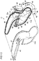
FIG. 1] FIG. 1 is a right side view illustrating a state in which, inside an engine room including an intake device according to an embodiment of the present invention, an engine is covered with a heat storage cover. - [
FIG. 2] FIG. 2 is a plan view illustrating a state in which the engine is covered with the heat storage cover (note that a top face cover portion is indicated by the chain line to represent an inside of the cover). - [
FIG. 3] FIG. 3 is a front view illustrating a state in which the engine is covered with the heat storage cover. - [
FIG. 4] FIG. 4 is a left side view illustrating a state in which the engine is covered with the heat storage cover. - [
FIG. 5] FIG. 5 is a perspective view illustrating an intake duct, an air cleaner, and the heat storage cover. - [
FIG. 6] FIG. 6 is a perspective view similar toFIG. 5 which is illustrated in a state in which the top face cover portion of the heat storage cover is excluded. - [
FIG. 7] FIG. 7 is a right side view illustrating the top face cover portion of the heat storage cover, a right-side face cover portion of the heat storage cover, and the intake duct. - [
FIG. 8] FIG. 8 is a perspective view illustrating a relationship between the intake duct and the right-side face cover, as viewed from the inside of the cover. - [
FIG. 9] FIG. 9 is a perspective view illustrating the intake duct, as viewed from the diagonally right front side. - [
FIG. 10] FIG. 10 is a perspective view illustrating the intake duct, as viewed from the diagonally left rear side. - [
FIG. 11] FIG. 11 is a plan view of the intake duct. - [
FIG. 12] FIG. 12 is a cross-sectional view taken along line XII-XII ofFIG. 11 . - [
FIG. 13] FIG. 13 is an exploded perspective view of the intake duct. - [
FIG. 14] FIG. 14 is a perspective view illustrating a second duct member of the intake duct in a state in which a passage switching mechanism is excluded. - [
FIG. 15] FIG. 15 is an exploded perspective view of the passage switching mechanism. - [
FIG. 16] FIG. 16 is a perspective view illustrating the passage switching mechanism in an assembled state. - [
FIG. 17] FIG. 17 is a front view illustrating a part of the assembled state of the passage switching mechanism. - [
FIG. 18] FIG. 18 is a perspective view illustrating a state in which the passage switching mechanism is assembled to the intake device. - Hereinafter, a mode for carrying out the present invention will be described based on the drawings. The following description of a preferred embodiment is merely illustrative in nature and is not intended to limit the present invention, applications thereof, or use thereof.
-
FIG. 1 illustrates an inside of anengine room 1 including an intake device for an engine according to the present embodiment. Theengine room 1 is provided as a recess open on the upper side in a vehicle front portion and accommodates anengine 2 and peripherals of theengine 2. The opening on the upper side of theengine room 1 is blocked by abonnet 3. Thebonnet 2 is openable and closable, so that the inside of theengine room 1 can be seen from the outside of a vehicle by opening thebonnet 3 as necessary. - Here, "the inside of the
engine room 1" refers to a space defined when the opening on the upper side of theengine room 1 is blocked by closing thebonnet 3. In the present description, the advancing-receding direction of the vehicle is referred to as "the front-rear direction," the advancing side is referred to as "the front side," and the receding side is referred to as "the rear side." Furthermore, the vehicle width direction is referred to as "the left-right direction." Furthermore, "the right side" and "the left side" are when the vehicle is viewed from the front side. - The
engine 2 includes acylinder block 4 and a cylinder head placed on thecylinder block 4. Anoil pan 5 is fixed to a bottom face of thecylinder block 4. Although not illustrated, a plurality of cylinders are formed inside thecylinder block 4. That is, theengine 2 is a multi-cylinder engine. A piston is slidably inserted into each cylinder. The piston is connected to a crankshaft via a connecting rod. The piston defines a combustion chamber of theengine 2 together with the cylinder and the cylinder head. - Fresh air is introduced into the combustion chamber of the
engine 2 through anintake duct 11 and anair cleaner 12. Theair cleaner 12 is a device that removes foreign matter such as dust or dirt contained in the fresh air to be introduced into the combustion chamber. -
FIG. 2 is a view of theengine 2 as viewed from the top, with atop face cover 22 of aheat storage cover 21, which will be described later, being removed. - As illustrated in the same figure, the fresh air passes through an
intake pipe 13 including a throttle valve from theair cleaner 12 and is introduced into asupercharger 14. Thesupercharger 14 increases the pressure of the fresh air to be introduced into the combustion chamber. Thesupercharger 14 of the present example is a mechanical supercharger that is driven via a belt by the crankshaft of theengine 2. Note that an electric supercharger or a turbosupercharger that is driven by exhaust energy may be adopted. The fresh air passing through thesupercharger 14 is cooled by anintercooler 15 illustrated inFIG. 3 and is introduced into the combustion chamber of each cylinder via a surge tank and an intake manifold. - As illustrated in
FIG. 2 , abypass pipe 16 bypassing thesupercharger 14 and leading the fresh air to the surge tank branches from theintake pipe 13. Thebypass pipe 16 is provided with a bypass valve that adjusts an opening area of a conduit of thebypass pipe 16. AnEGR pipe 17 illustrated inFIG. 1 is connected to a section upstream of the bypass valve of thebypass pipe 16. TheEGR pipe 17 returns, as EGR gas, a part of exhaust gas to the combustion chamber and includes anEGR cooler 18 that cools the EGR gas. - The
intake duct 11, theair cleaner 12, theintake pipe 13, thesupercharger 14, theintercooler 15, the surge tank, and the intake manifold which form an air intake system of theengine 2 are disposed on the front side of theengine 2, and an exhaust manifold and an exhaust pipe continuing to the exhaust manifold which form an exhaust system of theengine 2 are disposed on the rear side of theengine 2. That is, theengine 2 is a front intake and rear exhaust engine. - The
heat storage cover 21 is provided in theengine room 1, covers theengine 2 from above theengine 2, and surrounds the periphery of an upper portion of theengine 2. Heat dissipated from theengine 2 is stored inside theheat storage cover 21 through the medium of air, and theheat storage cover 21 blocks at least a part of upward heat dissipation. - The
heat storage cover 21 includes, as illustrated inFIG. 1 , the topface cover portion 22 covering theengine 2 from above, a rearface cover portion 23 continuous to the topface cover portion 22 and covering the upper portion of theengine 2 from behind, and a right-sideface cover portion 24 continuous to the topface cover portion 22 and covering the upper portion of theengine 2 from the right side, and further includes, as illustrated inFIG. 4 , a left-sideface cover portion 25 continuous to the topface cover portion 22 and covering the upper portion of theengine 2 from the left side. - A
radiator 6 that cools cooling water of theengine 2 by heat exchange with air is disposed in front of theengine 2 so as to cover theengine 2 from the front side. Agrille shutter 7 capable of blocking ventilation from the front side to theradiator 6 is provided in front of theradiator 6. Theradiator 6 includes, on the back side, aradiator fan 8 that dissipates heat of the cooling water toward theengine 2. Afront grille 9 is provided in front of thegrille shutter 7. - The
grille shutter 7 has a plurality offlaps 26 disposed at intervals in the up-down direction and includes an actuator that pivots each of the plurality offlaps 26. When theflaps 26 become horizontal as indicated by the chain line, ventilation from the front side to theradiator 6 is allowed, and when theflaps 26 become vertical as indicated by the solid line, the ventilation to theradiator 6 is blocked. When a passage switching mechanism of theintake duct 11, which will be described later, is operated and introduction of the fresh air into the combustion chamber of theengine 2 is brought into an inside air introduction state, in thegrille shutter 7, theflaps 26 become vertical, thereby suppressing hitting of vehicle traveling air against theradiator 6. As a result, heat dissipation from theengine room 1 to the front side is also suppressed. - Cooling
water inflow hoses 27 and 28 (seeFIGS. 2 and4 ) through which the cooling water from theengine 2 flows in, and a cooling water outflow hose (seeFIGS. 1 and2 ) 31 through which cooling water whose temperature has decreased is sent to awater pump 29 illustrated inFIG. 4 are connected to theradiator 6. - Here, the
heat storage cover 21 blocks heat dissipation from the upper portion of theengine 2 to the upper side and the periphery, thereby contributing to keeping theengine 2 warm. On the other hand, theradiator 6 and thegrille shutter 7 block heat dissipation from theengine 2 to the front side, thereby contributing to keeping theengine 2 warm. Furthermore, theradiator 6 emits the heat of the cooling water toward theengine 2 by using theradiator fan 8, thereby making heat storage of theheat storage cover 21 advantageous. - As illustrated in
FIG. 5 , theair cleaner 12 is disposed on the right outer side of theheat storage cover 21 as viewed from the vehicle front side. Theintake duct 11 is disposed on the outside of theheat storage cover 21 and on the front side of theair cleaner 12. - As illustrated in
FIGS. 1 ,4 , and5 , the topface cover portion 22 of theheat storage cover 21 includes anupper wall 22a gradually inclined downward toward the front side, andupper side walls FIGS. 1 and4 ) continuing to both side edges of theupper wall 22a and extending downward. Theupper wall 22a spreads outward relative to a top face of theengine 2 so as to cover the whole of the top face of theengine 2. A front end portion of theupper wall 22a is provided with a fixedportion 22d for fixing theheat storage cover 21 to aradiator shroud 20. - As illustrated in
FIGS. 1 ,4 , and6 , the rearface cover portion 23 of theheat storage cover 21 includes arear wall 23a spread in the left-right direction so as to cover a rear face of the upper portion of theengine 2, andrear side walls rear wall 23a and extending forward. Therear wall 23a includes abracket 23d protruding rearward for fixing theheat storage cover 21 to a cowl panel of the vehicle. As illustrated inFIG. 6 , an upper end of therear wall 23a and front end upper portions of therear side walls seal 32 for preventing a gap with respect to the topface cover portion 22 from occurring. That is, a rear end edge of each of theupper wall 22a and theupper side wall 22b in the topface cover portion 22 abuts against theseal 32. - As illustrated in
FIGS. 1 and7 , the right-sideface cover portion 24 of theheat storage cover 21 spreads in the front-rear direction so as to cover the upper portion of theengine 2 from the right side together with a right-side rear side wall of the rearface cover portion 23. A front end edge of the right-sideface cover portion 24 abuts against a protrusion 33 (seeFIGS. 7 and10 ) protruding rearward relative to theintake duct 11 and extending in the up-down direction. As illustrated inFIGS. 6 to 8 , a mountingpiece 34 protruding forward relative to an upper end of the front end edge of the right-sideface cover portion 24 is fixed to a mountingportion 33a of an upper end of theprotrusion 33 of theintake duct 11 by aclip 35 having a retaining function as a fastening member. A rear end edge of the right-sideface cover portion 24 abuts against a front end lower portion of the right-siderear side wall 23b of the rearface cover portion 23. - Here, as illustrated in
FIG. 7 , theintake duct 11 is provided with anoutside air inlet 44, which will be described later, at substantially the same height as an upper edge of the right-sideface cover portion 24, and is, when the whole of the duct is viewed from the lateral side, formed so as to include anupper portion 11a substantially horizontally extending rearward from the outsideair introduction port 44, anintermediate portion 11b continuing to theupper portion 11a and extending downward, and alower portion 11c continuing to theintermediate portion 11b, extending rearward, and connected to theair cleaner 12. As illustrated inFIG. 8 , theprotrusion 33 of theintake duct 11 passes through theintermediate portion 11b from a rear end of theupper portion 11a of theintake duct 11 and extends in the up-down direction up to thelower portion 11c, and as illustrated inFIG. 7 , thisprotrusion 33 is connected to a side edge on the front side of the right-sideface cover portion 24. That is, theintake duct 11 is continuous to the side edge on the front side of the right-sideface cover portion 24. Accordingly, theintake duct 11 functions as a cover member covering the upper portion of theengine 2 from the right side together with the right-sideface cover portion 24. - As illustrated in
FIG. 7 , the right-sideupper side wall 22b of the topface cover portion 22 is placed on the upper edge of the right-sideface cover portion 24 via aseal 36. At a lower edge of the right-sideupper side wall 22b of the topface cover portion 22 and the upper edge of the right-sideface cover portion 24,semicircular cutouts flexible pipe 37 extending toward theengine 2 from theair cleaner 12 illustrated inFIGS. 6 and8 passes. Theflexible pipe 37 is connected to theintake pipe 13 described earlier. - As illustrated in
FIGS. 4 and6 , the left-sideface cover portion 25 of theheat storage cover 21 spreads in the front-rear direction so as to cover the upper portion of theengine 2 from the left side together with the left-siderear side wall 23c of the rearface cover portion 23 and anengine mount 38. That is, the left-sideface cover portion 25 and the left-siderear side wall 23c of the rearface cover portion 23 are disposed on the front and rear sides of theengine mount 38. Accordingly, theengine mount 38 functions as a cover member covering the upper portion of theengine 2 from the left side together with the left-sideface cover portion 25. Theengine mount 38 has front andrear leg portions 38a fixed to a front side frame of the vehicle and has an upper portion on which theengine 2 is supported. In theengine mount 38, a space between the front andrear leg portions 38a is blocked from the viewpoint of obtaining a cover function. - As illustrated in
FIGS. 9 and10 , theintake duct 11 includes an outside airintroduction duct portion 41 for introducing outside air which is air outside theengine room 1 and an inside airintroduction duct portion 42 for introducing air inside theengine room 1, and is a composite duct in which bothduct portions downstream duct portion 43. - An upstream end of the outside air
introduction duct portion 41 is provided with theoutside air inlet 44 open forward and having a horizontally long rectangular shape. An upstream end of the inside airintroduction duct portion 42 is provided with aninside air inlet 45 open upward and having a horizontally long rectangular shape. At a downstream end of thedownstream duct portion 43, aconnection port 46 connected to theair cleaner 12 is open rearward. - As illustrated in
FIG. 11 , theintake duct 11 includes mountingpieces 47 protruding toward both sides of theupper portion 11a from theupper portion 11a extending rearward from theoutside air inlet 44 of the outside airintroduction duct portion 41. The downstream end of thedownstream duct portion 43 is provided with aflange 48 for connecting to theair cleaner 2. - In the
intake duct 11, the mountingpieces 47 are fixed to a top face of theradiator shroud 20 illustrated inFIG. 1 . Thus, theoutside air inlet 44 of the outside airintroduction duct portion 41 is provided so as to face forward from the top of theradiator shroud 20. On the other hand, as illustrated inFIG. 2 , theinside air inlet 45 of theintake duct 11 is provided between theengine 2 and theradiator 6 so as to face the inside of theheat storage cover 21 from below. Note that theinside air inlet 45 is covered with the outside airintroduction duct portion 41 and aprojection portion 51, which will be described later, from the top. - A part of the
inside air inlet 45 of the inside air introduction duct portion is covered with the outside airintroduction duct portion 41 from the top with a gap, and the remaining portion of theinside air inlet 45 is covered with theprojection portion 51 from the top with a gap. Hereinafter, this cover structure will be described. - As illustrated in
FIG. 9 , the outside airintroduction duct portion 41 and the inside airintroduction duct portion 42 branch from thedownstream duct portion 43 and rise so as to be arranged in the left-right direction, and the outside airintroduction duct portion 41 rises so as to be higher than theinside air inlet 45 of the inside airintroduction duct portion 42. - As illustrated in
FIGS. 10 and11 , the outside airintroduction duct portion 41, at a higher position than theinside air inlet 45 of the inside airintroduction duct portion 42, has aduct wall 41a curved toward the inside airintroduction duct portion 42 side and extending forward diagonally across above theinside air inlet 45 of the inside airintroduction duct portion 42. As also illustrated inFIGS. 11 and12 , a front-side portion of theinside air inlet 45 of the inside airintroduction duct portion 42 is formed so as to be covered by thisduct wall 41a from above. A portion extending forward from theduct wall 41a of the outside airintroduction duct portion 41 forms theupper portion 11a of theintake duct 11. - The outside air
introduction duct portion 41 includes theprojection portion 51 having a collar-like shape and protruding rearward above theinside air inlet 45 of the inside airintroduction duct portion 42 from a rear face of theduct wall 41a. Thisprojection portion 51 covers the remaining portion of theinside air inlet 45 from above. As illustrated inFIG. 10 , theprojection portion 51 is inclined downward toward a rising portion of the outside airintroduction duct portion 41, and this inclined portion covers theinside air inlet 45 from the lateral side, that is, from the diagonally upper side. - From the viewpoint of prevention of entry of foreign matter, it is advantageous that an interval between the
projection portion 51 and the inside air take-inport 45 is as narrow as possible. If it is desired to prevent entry of a bolt during assembly, it is conceivable that, for example, the interval between theprojection portion 51 and the inside air take-inport 45 is set so as to be smaller than the diameter of an M6 nut. Note that if the interval is narrowed excessively, theprojection portion 51 serves as a ventilation resistance and prevents inside air from being brought into the inside air take-inport 45. Accordingly, the interval between theprojection portion 51 and the inside air take-inport 45 is preferably set in a range of, for example, 10 to 60 mm in comprehensive consideration of these problems. In the present embodiment, this interval is 40 mm. - The passage switching mechanism of the
intake duct 11 switches the introduction of the fresh air into the combustion chamber of theengine 2 between an outside air introduction state in which outside air outside theengine room 1 is introduced into theair cleaner 4 by the outside airintroduction duct portion 41, and the inside air introduction state in which air in theengine room 1, in particular, hot air obtained by theheat storage cover 21, is introduced into theair cleaner 4 by the inside airintroduction duct portion 42. Thus, the passage switching mechanism includes afirst valve 61 and asecond valve 62, which will be described later. - As illustrated in
FIG. 13 , theintake duct 11 is formed by afirst duct member 11A made of synthetic resin and asecond duct member 11B made of synthetic resin being mated at respective peripheral edge portions and welded together. In the present example, thefirst duct member 11A forms a front portion of theintake duct 11 including theoutside air inlet 44 of the outside airintroduction duct portion 41. Thesecond duct member 11B forms a rear portion of theintake duct 11 including theconnection port 46 of thedownstream duct portion 43. Thefirst duct member 11A and thesecond duct member 11B are mated, so that the outside airintroduction duct portion 41, inside airintroduction duct portion 42, anddownstream duct portion 43 of theintake duct 11 are completed. - As illustrated in
FIG. 13 , the outside airintroduction duct portion 41 forms an outsideair introduction passage 55, and the insideair introduction duct 42 forms an insideair introduction passage 56. The outsideair introduction passage 55 and the insideair introduction passage 56 continue to adownstream introduction passage 57 formed by thedownstream duct portion 43. Thefirst valve 61 that opens and closes the outsideair introduction passage 55 is disposed in the outside airintroduction duct portion 41, and thesecond valve 62 that opens and closes the insideair introduction passage 56 is disposed in the inside airintroduction duct portion 42. - As described earlier, the outside air
introduction duct portion 41 and the inside airintroduction duct portion 42 branch from thedownstream duct portion 43 and rise so as to be arranged in the left-right direction, and thefirst valve 61 and thesecond valve 62 are disposed at base ends of the rising of the outside airintroduction duct portion 41 and the rising of the inside airintroduction duct portion 42. That is, a first valve disposition portion of the outsideair introduction passage 55 and a second valve disposition portion of the insideair introduction passage 56 are provided in parallel across apartition wall 58 separating bothpassages - The
first duct member 11A forms a part of the first valve disposition portion of the outsideair introduction passage 55 and a part of the second valve disposition portion of the insideair introduction passage 56 in respective passage wall circumferential directions, and thesecond duct member 11B forms the remaining portions thereof in the passage wall circumferential directions. - The
first valve 61 is a flap-type valve, and thesecond valve 62 is a butterfly-type valve. That is, bothvalves rotation shaft 63 extending over both of the outside airintroduction duct portion 41 and the inside airintroduction duct portion 42. Bothvalves rotation shaft 63 and supported so that, when either one of them is open, the other one is closed. - The
rotation shaft 63 is supported on thesecond duct member 11B forming the rear portion of theintake duct 11, and anactuator 64 that rotationally drives therotation shaft 63 is also supported on thesecond duct member 11B. That is, as illustrated inFIG. 14 , thesecond duct member 11B is provided withshaft support portions second duct member 11B to solely support therotation shaft 63, and anactuator support portion 67 for allowing thesecond duct member 11B to solely support theactuator 64. - In the present example, the
shaft support portions introduction duct portion 41 side and on the inside airintroduction duct portion 42 side in thesecond duct member 11B. Theactuator support portion 67 is provided on an outside face on the outside airintroduction duct portion 41 side in thesecond duct member 11B. - As described above, the
rotation shaft 63 is supported on thesecond duct member 11B, so that thefirst valve 61 and thesecond valve 62 are also supported on thesecond duct member 11B by thesecond duct member 11B alone. - As illustrated in
FIG. 14 , theshaft support portion 66 on the inside airintroduction duct portion 42 side is provided with asupport hole 71, and abush 72 illustrated inFIG. 15 is fitted to thesupport hole 71. Similarly, theshaft support portion 65 on the outside airintroduction duct portion 41 side is provided with a support hole 71 (illustration omitted), and abush 72 illustrated inFIG. 15 is fitted to thesupport hole 71. - As illustrated in
FIG. 15 , therotation shaft 63 is a shaft having a square shape (rectangular cross-section in the present example) and is passed through cylindricalfitting portions 73 to 77 provided at shaft portions of thefirst valve 61 and thesecond valve 62. Thefirst valve 61 is provided with, at two locations on both sides in the axis direction, thefitting portions first valve 61. Thesecond valve 62 is provided with, at two locations on both sides in the axis direction, thefitting portions second valve 62, and is provided with thefitting portion 77 at one intermediate location. - Outer circumferential faces of the
fitting portions 73 to 77 in thefirst valve 61 and thesecond valve 62 are circular, while fitting holes thereof all have a square shape corresponding to the cross-sectional shape of therotation shaft 63. Therotation shaft 63 is passed through the fitting holes of thefitting portions 73 to 77 of bothvalves valves rotation shaft 63. - In a state in which the
rotation shaft 63 is passed through thefitting portions 73 to 77 of thevalves fitting portions fitting portions 73 to 77 are fitted to thebushes 72 of theshaft support portions rotation shaft 63 is rotatably supported on thebushes 72 of theshaft support portions fitting portions valves - Axially opposed end portions of the
fitting portion 74 of thefirst valve 61 and thefitting portion 75 of thesecond valve 62 which are axially adjacent to each other have a shape cut out in a semi-cylindrical shape, and the cutout portions areengagement portions engagement portions rotation shaft 63 is passed through thefitting portions 73 to 77, and regulate a relative position between thefirst valve 61 and thesecond valve 62 in the valve rotation direction. - That is, as illustrated in
FIG. 16 , when, in a state in which theengagement portions valves rotation shaft 63 is passed through thefitting portions 73 to 77 of bothvalves valves rotation shaft 63 so that, by rotation of therotation shaft 63, when either one of them is open, the other one is closed. In the case of the present example, bothvalves - The
fitting portion 74 of thefirst valve 61 and thefitting portion 75 of thesecond valve 62 which are adjacent to each other are respectively provided withprojections spacer 81 illustrated inFIG. 15 to regulate positions of bothvalves - Hereinafter, specific description will be given. As illustrated in
FIG. 14 , in thepartition wall 58 of thesecond duct member 11B, aspacer receiver 85 is formed which has arecess 84 to which thefitting portions fitting groove 86 is formed in thisspacer receiver 85. On the other hand, arecess 87 corresponding to therecess 84 of thespacer receiver 85 and aridge 88 to be fitted to thefitting groove 86 are formed in thespacer 81. Thespacer 81 is dimensioned so that the length thereof in the valve axis direction is equivalent to an interval between theprojections valves introduction duct portion 41 and the inside airintroduction duct portion 42. - In a state in which the
first valve 61 and thesecond valve 62 are set in thesecond duct member 11B, theridge 88 is fitted to thefitting groove 86, so that thespacer 81 is placed in thespacer receiver 85. At this time, as illustrated inFIG. 17 , theprojection 82 on thefirst valve 61 side abuts against one side of thespacer 81, and theprojection 83 on thesecond valve 62 side abuts against the opposite side of thespacer 81. Theprojections spacer 81 in the valve axis direction, so that, in bothvalves - The
bush 72 illustrated inFIG. 15 is fitted to thesupport hole 71 of each of theshaft support portions second duct member 11B illustrated inFIG. 14 . - As illustrated in
FIG. 18(a) , thefirst valve 61 is put in the valve disposition portion (first valve disposition portion) on the outside airintroduction duct portion 41 side of thesecond duct member 11B. Thefirst valve 61 is moved in the valve axis direction to fit thefitting portion 73 to thebush 72 of theshaft support portion 65. - As illustrated in
FIG. 18(b) , thefirst valve 61 is positioned at a predetermined rotation angle. That is, in the present example, thefirst valve 61 rotates so as to abut against a passage wall on the back side of the outside airintroduction duct portion 41. - As illustrated in
FIG. 18(c) , in a state in which thefirst valve 61 is positioned as described above, thesecond valve 62 is put in the valve disposition portion (second valve disposition portion) on the inside airintroduction duct portion 42 side of thesecond duct member 11B. At this time, theengagement portion 78 of thefirst valve 61 and theengagement portion 79 of thesecond valve 62 are engaged. Thus, bothvalves second valve 62 is moved in the valve axis direction to fit thefitting portion 76 to the bush 72 (seeFIG. 15 ) of theshaft support portion 66. - As illustrated in
FIG. 18(d) , thespacer 81 is fitted to thespacer receiver 85, and theprojection 82 of thefirst valve 61 and theprojection 83 of thesecond valve 62 abut against both side faces of thespacer 81. Thus, the positions of thefirst valve 61 and thesecond valve 62 in the outside airintroduction duct portion 41 and the inside airintroduction duct portion 42 in the valve axis direction are brought into a state of being regulated to planned positions. - As illustrated in
FIG. 18(e) , therotation shaft 63 whose end portion illustrated inFIG. 15 is coupled to agear 89 is inserted into thefitting portions first valve 61 and thefitting portions 75 to 77 of thesecond valve 62 from outside the outside airintroduction duct portion 41 via thebush 72 of theshaft support portion 65. Thegear 89 is provided with astopper 90 illustrated inFIG. 15 , and thestopper 90 abuts against thesecond duct member 11B, so that therotation shaft 63 is positioned in the axis direction. - Thereafter, the
first duct member 11A and thesecond duct member 11B are welded together. Then, mounting of acap 91 illustrated inFIG. 15 , theactuator 64, and abell mouth 92 is performed. That is, thecap 91 is fitted to theshaft support portion 66 on the inside airintroduction duct portion 42 side from outside. A gear coupled to an output shaft of theactuator 64 meshes with thegear 89 of therotation shaft 63, and theactuator 64 is mounted on theactuator support portion 67 on thesecond duct member 11B side. Thebell mouth 92 is fitted to theinside air inlet 45 of the inside airintroduction duct portion 42. - Note that the
cap 91 and theactuator 61 may be first mounted on thesecond duct member 11B and then thefirst duct member 11A and thesecond duct member 11B may be welded together. - According to the embodiment, the
first valve 61 and thesecond valve 62 are operated by theactuator 61 illustrated inFIG. 13 , so that switching can be made between the outside air introduction state in which the outsideair introduction passage 55 of theintake duct 11 is open and the insideair introduction passage 56 is closed, and the inside air introduction state in which the outsideair introduction passage 55 is closed and the insideair introduction passage 56 is open. - In the outside air introduction state, the air outside the
engine room 1 illustrated inFIG. 1 passes through the outsideair introduction passage 55 illustrated inFIG. 13 and the like from theoutside air inlet 44 of theintake duct 11 and enters theair cleaner 12, and the outside air is introduced into the combustion chamber of theengine 2. In the inside air introduction state, the air inside theengine room 1 passes through the insideair introduction passage 56 from theinside air inlet 45 of theintake duct 11 and enters theair cleaner 12, and high temperature inside air in theengine room 1 is introduced into the combustion chamber of theengine 2. - The inside air introduction state will be described. Air around the
engine 2 is warmed by the heat dissipated from theengine 2 and rises, and the air enters the inside of theheat storage cover 21. Theheat storage cover 21 blocks the upward (bonnet 3 side) heat dissipation, so that the heat dissipated from theengine 2 is stored inside theheat storage cover 21 through the medium of air. As a result, the temperature of air inside theheat storage cover 21 or below theheat storage cover 21 becomes high. - The
inside air inlet 45 of theintake duct 11 faces the inside of theheat storage cover 21 from the bottom, so that the high temperature air obtained by theheat storage cover 21 is brought into the insideair introduction passage 56 of theintake duct 11. Accordingly, the high temperature air is introduced into the combustion chamber of theengine 2 through theair cleaner 12, so that, for example, even when a large amount of air is required as in a lean combustion, a decrease in temperature of the combustion chamber is suppressed, which is advantageous in securing combustion stability of theengine 2. - In the embodiment, the
radiator 6 illustrated inFIG. 1 serves to prevent heat dissipation from theengine 2 to the front side, and waste heat released from the radiator 6 (heat taken from the cooling water by heat exchange) is supplied to theengine 2 side by theradiator fan 8. Thus, the temperature of air between theengine 2 and theradiator 6 becomes high. Furthermore, an escape of the heat to the rear side and lateral side of theengine 2 is suppressed by the rearface cover portion 23 and the sideface cover portions heat storage cover 21, so that the high temperature air is easily stored between theengine 2 and theradiator 6 in front of theengine 2. - Thus, as illustrated in
FIG. 2 , theinside air inlet 45 is disposed between theengine 2 and theradiator 6, so that it is advantageous in increasing the temperature of the air to be brought into theintake duct 11. Furthermore, during the inside air introduction state, ventilation to theradiator 6 is blocked by thegrille shutter 7 illustrated inFIG. 1 , so that a thermal insulating property on the radiator side of theengine 2 is increased, which is advantageous in introducing the high temperature air into the combustion chamber. - Note that the invention according to introduction of air into an engine combustion chamber is a technique useful for suppressing a decrease in temperature of the combustion chamber and is applicable not only to a lean combustion mode but also to a combustion mode in the vicinity of a so-called theoretical air-fuel ratio.
- Furthermore, although the whole of an opening of the
inside air inlet 45 of the embodiment faces the inside of theheat storage cover 21 from the bottom, a part of the opening may protrude outside theheat storage cover 21. The temperature of air becomes high in the vicinity of theheat storage cover 21 due to influence of theheat storage cover 21, so that, even in a case where a part of theinside air inlet 45 protrudes outside theheat storage cover 21 and air outside theheat storage cover 21 is partially brought into theintake duct 11, the high temperature air can be introduced into the engine combustion chamber. - According to the embodiment, as illustrated in
FIG. 2 , in the front intake andrear exhaust engine 2, theinside air inlet 45 is disposed on the front side of theengine 2, so that the insideair introduction passage 56 from theinside air inlet 45 to theair cleaner 12 does not become long, which is advantageous in introducing the high temperature air into the combustion chamber and also facilitates the layout of theintake duct 11. - As illustrated in
FIGS. 6 to 8 , theintake duct 11 is continuous to the side edge on the front side of the right-sideface cover portion 24, so that theintake duct 11 approaches theengine 2 as compared with a case where theintake duct 11 is disposed outside the sideface cover portion 24. This avoids an increase in a space occupied by, in theengine room 2, theheat storage cover 21 and air intake system components including theintake duct 11, facilitating the layouts of theheat storage cover 21 and the air intake system components in theengine room 2. - Furthermore, the
intake duct 11 has a function of covering theengine 2 from the right side, so that the right-sideface cover portion 24 can be made small accordingly. Similarly, regarding the left-sideface cover portion 25, theengine mount 38 has a function of covering theengine 2 from the left side, so that the left-sideface cover portion 25 can be made small accordingly. - By the shortening of the inside
air introduction passage 56 and the downsizing of the sideface cover portions - The
intake duct 11 and the right-sideface cover portion 24 are coupled together by the clip 35 (fastening member), so that the coupling is facilitated and theintake duct 11 can be used for support of the right-sideface cover portion 24, which is advantageous in reducing the number of components and enhancing mounting stability of the right-sideface cover portion 24. - As illustrated in
FIG. 9 and the like, theinside air inlet 45 of theintake duct 11 is open upward, so that foreign matter entering theengine room 1 from the horizontal direction or the lower side is less likely to enter theinside air inlet 45, avoiding damage to the passage switching mechanism including thesecond valve 62 of theintake duct 11. In particular, in the embodiment, as illustrated inFIG. 2 , theinside air inlet 45 is covered with theheat storage cover 21 from the top, so that it is advantageous in terms of entry of the foreign matter. - On the other hand, while the
inside air inlet 45 of the inside airintroduction duct portion 42 is open upward, as illustrated inFIGS. 11 and12 , theduct wall 41a of the outside airintroduction duct portion 41 is across above theinside air inlet 45, and in addition, theprojection portion 51 bulges above theinside air inlet 45. That is, the upper side of theinside air inlet 45 is covered not only with theduct wall 41a of the outside airintake duct portion 41 but also with theprojection portion 45. Accordingly, if theheat storage cover 21 is removed in maintenance or the like, foreign matter such as a bolt is blocked by theduct wall 41a of the outside airintroduction duct portion 41 and theprojection portion 51 and thus is avoided from entering theinside air inlet 45. - Furthermore, the passage switching mechanism composed of the
valves intake duct 11. The passage switching mechanism, in particular, thesecond valve 62, might be damaged by foreign matter entering the inside of theintake duct 11 from theinside air inlet 45. Accordingly, the upper side of theinside air inlet 45 is covered with the outside airintroduction duct portion 41 so as to avoid entry of foreign matter into theinside air inlet 45, thereby preventing damage to the passage switching mechanism inside the intake duct 11 (in particular, the second valve 62) due to entry of foreign matter into the inside of theintake duct 11. - While the
intake duct 11 is formed by welding of thefirst duct member 11A and thesecond duct member 11B, as illustrated inFIG. 13 , a structure is adopted in which theshaft support portions rotation shaft 63 of the passage switching mechanism, and theactuator support portion 67 supporting theactuator 64 are provided in thesecond duct member 11B and in which thisrotation shaft 63 and thisactuator 64 are supported by thesecond duct member 11B alone. Accordingly, if, due to welding of bothduct members rotation shaft 63 and theactuator 64 is small. This avoids the occurrence of a malfunction of the passage switching mechanism. - As illustrated in
FIGS. 15 to 17 , when thefitting portion 74 of thefirst valve 61 and thefitting portion 75 of thesecond valve 62 which form the passage switching mechanism are engaged at theirengagement portions valves valves valves rotation shaft 63. - Furthermore, the relative position between both
valves projections fitting portions valves 61 arid 62 with thespacer 81. Accordingly, the positions of bothvalves spacer 81 on thesecond duct member 11B in a state in which bothvalves engagement portions - As described above, according to the embodiment, by the simple configuration in which the
engagement portions projections fitting portions valves spacer 81 to be mounted on thesecond duct member 11B is provided, it is advantageous in assembling bothvalves valves -
- 1
- engine room
- 2
- engine
- 3
- bonnet
- 4
- cylinder block
- 5
- oil pan
- 6
- radiator
- 7
- grille shutter
- 8
- radiator fan
- 11
- intake duct
- 11A
- first duct member
- 11B
- second duct member
- 12
- air cleaner
- 21
- heat storage cover
- 22
- top face cover portion
- 23
- rear face cover portion
- 24
- right-side face cover portion
- 25
- left-side face cover portion
- 35
- clip (fastening member)
- 41
- outside air introduction duct portion
- 41a
- duct wall
- 42
- inside air introduction duct portion
- 43
- downstream duct portion
- 44
- outside air inlet
- 45
- inside air inlet
- 51
- projection portion
- 55
- outside air introduction passage
- 56
- inside air introduction passage
- 57
- downstream introduction passage
- 61
- first valve
- 62
- second valve
- 63
- rotation shaft
- 64
- actuator
- 73 to 77
- fitting portion
- 78, 79
- engagement portion
- 81
- spacer
Claims (5)
- An intake device for an engine, comprising an intake passage for introducing air in an engine room into a combustion chamber of the engine, the intake device comprising
a heat storage cover provided in the engine room, which covers the engine from above and at least partially surrounds a periphery of the engine to internally store, through a medium of air, heat dissipated from the engine and block at least a part of upward heat dissipation, characterized in that
the intake passage comprises an air inlet for introducing, into the combustion chamber, high temperature air obtained by the heat storage cover blocking the upward heat dissipation. - The intake device for an engine according to claim 1, characterized in that the air inlet of the intake passage faces an inside of the heat storage cover.
- The intake device for an engine according to claim 1 or 2, characterized in that
the engine room comprises a radiator that dissipates heat of cooling water of the engine toward the engine, and
the air inlet of the intake passage is disposed between the engine and the radiator. - The intake device for an engine according to claim 3, characterized in that
the engine room is provided in a front portion of a vehicle,
the engine is a front intake and rear exhaust engine,
the heat storage cover comprises:a top face cover portion covering the engine from above;a rear face cover portion covering the engine from behind; andside face cover portions covering the engine from both sides,the radiator is disposed so as to cover the engine from a front side, andbetween the engine and the radiator, the air inlet of the intake passage faces an inside of the heat storage cover. - The intake device for an engine according to claim 3 or 4, characterized by comprising a shutter that, when the high temperature air obtained by the heat storage cover is introduced into the combustion chamber, blocks ventilation to the radiator.
Applications Claiming Priority (2)
| Application Number | Priority Date | Filing Date | Title |
|---|---|---|---|
| JP2018169779A JP7176311B2 (en) | 2018-09-11 | 2018-09-11 | engine intake system |
| PCT/JP2019/034606 WO2020054512A1 (en) | 2018-09-11 | 2019-09-03 | Engine air intake device |
Publications (3)
| Publication Number | Publication Date |
|---|---|
| EP3832120A1 true EP3832120A1 (en) | 2021-06-09 |
| EP3832120A4 EP3832120A4 (en) | 2021-08-25 |
| EP3832120B1 EP3832120B1 (en) | 2023-05-03 |
Family
ID=69778324
Family Applications (1)
| Application Number | Title | Priority Date | Filing Date |
|---|---|---|---|
| EP19859563.9A Active EP3832120B1 (en) | 2018-09-11 | 2019-09-03 | Vehicle with engine and air intake device |
Country Status (5)
| Country | Link |
|---|---|
| US (1) | US11371474B2 (en) |
| EP (1) | EP3832120B1 (en) |
| JP (1) | JP7176311B2 (en) |
| CN (1) | CN112654780B (en) |
| WO (1) | WO2020054512A1 (en) |
Families Citing this family (1)
| Publication number | Priority date | Publication date | Assignee | Title |
|---|---|---|---|---|
| JP7073885B2 (en) * | 2018-04-23 | 2022-05-24 | トヨタ自動車株式会社 | Internal combustion engine sound insulation system |
Family Cites Families (11)
| Publication number | Priority date | Publication date | Assignee | Title |
|---|---|---|---|---|
| US2109633A (en) * | 1935-05-09 | 1938-03-01 | Cross Roland Claude | Insulating internal combustion engine |
| US3882951A (en) * | 1973-01-22 | 1975-05-13 | Hallamore Inc | Quiet slide out engine vehicle |
| JPS6398478U (en) * | 1986-12-17 | 1988-06-25 | ||
| JP3872189B2 (en) * | 1997-11-07 | 2007-01-24 | トヨタ自動車株式会社 | Intake air temperature control device for vehicle engine |
| JP4853641B2 (en) * | 2006-11-24 | 2012-01-11 | トヨタ自動車株式会社 | Fuel cell vehicle |
| AU2007202877B2 (en) | 2007-06-21 | 2013-09-05 | Gilberto Abu Gannam | Charge Air Heater |
| JP2009167932A (en) | 2008-01-17 | 2009-07-30 | Toyota Motor Corp | Internal combustion engine control device |
| JP5411186B2 (en) | 2011-03-18 | 2014-02-12 | アイシン精機株式会社 | Grill shutter control device |
| JP6449077B2 (en) * | 2015-03-27 | 2019-01-09 | 愛三工業株式会社 | Intake air temperature control device for vehicle engine |
| JP6274241B2 (en) | 2016-03-29 | 2018-02-07 | マツダ株式会社 | Engine heat insulation structure |
| JP6330841B2 (en) | 2016-03-29 | 2018-05-30 | マツダ株式会社 | Heating cover mounting structure |
-
2018
- 2018-09-11 JP JP2018169779A patent/JP7176311B2/en active Active
-
2019
- 2019-09-03 US US17/274,005 patent/US11371474B2/en active Active
- 2019-09-03 WO PCT/JP2019/034606 patent/WO2020054512A1/en unknown
- 2019-09-03 CN CN201980058132.0A patent/CN112654780B/en active Active
- 2019-09-03 EP EP19859563.9A patent/EP3832120B1/en active Active
Also Published As
| Publication number | Publication date |
|---|---|
| CN112654780A (en) | 2021-04-13 |
| US11371474B2 (en) | 2022-06-28 |
| CN112654780B (en) | 2022-12-02 |
| EP3832120B1 (en) | 2023-05-03 |
| WO2020054512A1 (en) | 2020-03-19 |
| JP7176311B2 (en) | 2022-11-22 |
| US20210254585A1 (en) | 2021-08-19 |
| JP2020041489A (en) | 2020-03-19 |
| EP3832120A4 (en) | 2021-08-25 |
Similar Documents
| Publication | Publication Date | Title |
|---|---|---|
| US8671919B2 (en) | Intake device of engine | |
| US10308315B2 (en) | Saddle-ridden vehicle | |
| JP6718573B2 (en) | Engine equipment | |
| JP5192540B2 (en) | Work vehicle | |
| EP3832120B1 (en) | Vehicle with engine and air intake device | |
| EP3832121B1 (en) | Engine air intake device | |
| JP2017187006A (en) | Engine device | |
| JP7110854B2 (en) | Engine air intake device and its assembly method | |
| JP7096678B2 (en) | Internal combustion engine for automobiles | |
| JP7159722B2 (en) | engine intake system | |
| JPH11148431A (en) | Deicing structure of inlet throttle valve | |
| US8925530B2 (en) | Intake module with integrated exhaust gas recirculation | |
| JP5942453B2 (en) | Intake device for vehicle engine | |
| JP6928426B2 (en) | Engine equipment | |
| JP6900154B2 (en) | Engine equipment | |
| JP3754163B2 (en) | Water pump housing structure in outdoor unit of water cooling engine drive heat pump device | |
| JP2022119769A (en) | engine device | |
| JP6344404B2 (en) | Engine intake cooling system | |
| JP2017187009A (en) | Engine device | |
| JP6811546B2 (en) | Engine equipment | |
| JP2020115016A (en) | Engine device | |
| JP2023150677A (en) | Egr device for internal combustion engine | |
| JP2020197219A (en) | Engine device | |
| JP2020197218A (en) | Engine device | |
| JP5812688B2 (en) | Exhaust gas recirculation device |
Legal Events
| Date | Code | Title | Description |
|---|---|---|---|
| STAA | Information on the status of an ep patent application or granted ep patent |
Free format text: STATUS: THE INTERNATIONAL PUBLICATION HAS BEEN MADE |
|
| PUAI | Public reference made under article 153(3) epc to a published international application that has entered the european phase |
Free format text: ORIGINAL CODE: 0009012 |
|
| STAA | Information on the status of an ep patent application or granted ep patent |
Free format text: STATUS: REQUEST FOR EXAMINATION WAS MADE |
|
| 17P | Request for examination filed |
Effective date: 20210304 |
|
| AK | Designated contracting states |
Kind code of ref document: A1 Designated state(s): AL AT BE BG CH CY CZ DE DK EE ES FI FR GB GR HR HU IE IS IT LI LT LU LV MC MK MT NL NO PL PT RO RS SE SI SK SM TR |
|
| A4 | Supplementary search report drawn up and despatched |
Effective date: 20210723 |
|
| RIC1 | Information provided on ipc code assigned before grant |
Ipc: F02M 35/10 20060101AFI20210719BHEP Ipc: B60K 11/04 20060101ALI20210719BHEP Ipc: B60K 13/02 20060101ALI20210719BHEP Ipc: F01P 3/18 20060101ALI20210719BHEP Ipc: F01P 11/10 20060101ALI20210719BHEP Ipc: F02B 77/11 20060101ALI20210719BHEP Ipc: F02B 77/13 20060101ALI20210719BHEP Ipc: F02M 31/06 20060101ALI20210719BHEP Ipc: F02M 31/04 20060101ALI20210719BHEP Ipc: F02M 31/02 20190101ALI20210719BHEP Ipc: F02M 31/14 20060101ALI20210719BHEP Ipc: F02M 35/16 20060101ALI20210719BHEP |
|
| DAV | Request for validation of the european patent (deleted) | ||
| DAX | Request for extension of the european patent (deleted) | ||
| REG | Reference to a national code |
Ref document number: 602019028522 Country of ref document: DE Ref country code: DE Ref legal event code: R079 Free format text: PREVIOUS MAIN CLASS: F02M0035100000 Ipc: F02M0031040000 |
|
| GRAP | Despatch of communication of intention to grant a patent |
Free format text: ORIGINAL CODE: EPIDOSNIGR1 |
|
| STAA | Information on the status of an ep patent application or granted ep patent |
Free format text: STATUS: GRANT OF PATENT IS INTENDED |
|
| RIC1 | Information provided on ipc code assigned before grant |
Ipc: F01P 1/00 19680901ALI20230103BHEP Ipc: F02B 77/13 19800101ALI20230103BHEP Ipc: F02M 35/16 19680901ALI20230103BHEP Ipc: F02M 35/10 19680901ALI20230103BHEP Ipc: F02M 31/14 19680901ALI20230103BHEP Ipc: F02M 31/06 19680901ALI20230103BHEP Ipc: F02M 31/02 19680901ALI20230103BHEP Ipc: F02M 31/04 19680901AFI20230103BHEP |
|
| INTG | Intention to grant announced |
Effective date: 20230131 |
|
| GRAS | Grant fee paid |
Free format text: ORIGINAL CODE: EPIDOSNIGR3 |
|
| GRAA | (expected) grant |
Free format text: ORIGINAL CODE: 0009210 |
|
| STAA | Information on the status of an ep patent application or granted ep patent |
Free format text: STATUS: THE PATENT HAS BEEN GRANTED |
|
| AK | Designated contracting states |
Kind code of ref document: B1 Designated state(s): AL AT BE BG CH CY CZ DE DK EE ES FI FR GB GR HR HU IE IS IT LI LT LU LV MC MK MT NL NO PL PT RO RS SE SI SK SM TR |
|
| REG | Reference to a national code |
Ref country code: GB Ref legal event code: FG4D |
|
| REG | Reference to a national code |
Ref country code: DE Ref legal event code: R096 Ref document number: 602019028522 Country of ref document: DE |
|
| REG | Reference to a national code |
Ref country code: AT Ref legal event code: REF Ref document number: 1564794 Country of ref document: AT Kind code of ref document: T Effective date: 20230515 Ref country code: CH Ref legal event code: EP |
|
| REG | Reference to a national code |
Ref country code: IE Ref legal event code: FG4D |
|
| REG | Reference to a national code |
Ref country code: LT Ref legal event code: MG9D |
|
| REG | Reference to a national code |
Ref country code: NL Ref legal event code: MP Effective date: 20230503 |
|
| REG | Reference to a national code |
Ref country code: AT Ref legal event code: MK05 Ref document number: 1564794 Country of ref document: AT Kind code of ref document: T Effective date: 20230503 |
|
| PG25 | Lapsed in a contracting state [announced via postgrant information from national office to epo] |
Ref country code: SE Free format text: LAPSE BECAUSE OF FAILURE TO SUBMIT A TRANSLATION OF THE DESCRIPTION OR TO PAY THE FEE WITHIN THE PRESCRIBED TIME-LIMIT Effective date: 20230503 Ref country code: PT Free format text: LAPSE BECAUSE OF FAILURE TO SUBMIT A TRANSLATION OF THE DESCRIPTION OR TO PAY THE FEE WITHIN THE PRESCRIBED TIME-LIMIT Effective date: 20230904 Ref country code: NO Free format text: LAPSE BECAUSE OF FAILURE TO SUBMIT A TRANSLATION OF THE DESCRIPTION OR TO PAY THE FEE WITHIN THE PRESCRIBED TIME-LIMIT Effective date: 20230803 Ref country code: NL Free format text: LAPSE BECAUSE OF FAILURE TO SUBMIT A TRANSLATION OF THE DESCRIPTION OR TO PAY THE FEE WITHIN THE PRESCRIBED TIME-LIMIT Effective date: 20230503 Ref country code: ES Free format text: LAPSE BECAUSE OF FAILURE TO SUBMIT A TRANSLATION OF THE DESCRIPTION OR TO PAY THE FEE WITHIN THE PRESCRIBED TIME-LIMIT Effective date: 20230503 Ref country code: AT Free format text: LAPSE BECAUSE OF FAILURE TO SUBMIT A TRANSLATION OF THE DESCRIPTION OR TO PAY THE FEE WITHIN THE PRESCRIBED TIME-LIMIT Effective date: 20230503 |
|
| PG25 | Lapsed in a contracting state [announced via postgrant information from national office to epo] |
Ref country code: RS Free format text: LAPSE BECAUSE OF FAILURE TO SUBMIT A TRANSLATION OF THE DESCRIPTION OR TO PAY THE FEE WITHIN THE PRESCRIBED TIME-LIMIT Effective date: 20230503 Ref country code: PL Free format text: LAPSE BECAUSE OF FAILURE TO SUBMIT A TRANSLATION OF THE DESCRIPTION OR TO PAY THE FEE WITHIN THE PRESCRIBED TIME-LIMIT Effective date: 20230503 Ref country code: LV Free format text: LAPSE BECAUSE OF FAILURE TO SUBMIT A TRANSLATION OF THE DESCRIPTION OR TO PAY THE FEE WITHIN THE PRESCRIBED TIME-LIMIT Effective date: 20230503 Ref country code: LT Free format text: LAPSE BECAUSE OF FAILURE TO SUBMIT A TRANSLATION OF THE DESCRIPTION OR TO PAY THE FEE WITHIN THE PRESCRIBED TIME-LIMIT Effective date: 20230503 Ref country code: IS Free format text: LAPSE BECAUSE OF FAILURE TO SUBMIT A TRANSLATION OF THE DESCRIPTION OR TO PAY THE FEE WITHIN THE PRESCRIBED TIME-LIMIT Effective date: 20230903 Ref country code: HR Free format text: LAPSE BECAUSE OF FAILURE TO SUBMIT A TRANSLATION OF THE DESCRIPTION OR TO PAY THE FEE WITHIN THE PRESCRIBED TIME-LIMIT Effective date: 20230503 Ref country code: GR Free format text: LAPSE BECAUSE OF FAILURE TO SUBMIT A TRANSLATION OF THE DESCRIPTION OR TO PAY THE FEE WITHIN THE PRESCRIBED TIME-LIMIT Effective date: 20230804 |
|
| PGFP | Annual fee paid to national office [announced via postgrant information from national office to epo] |
Ref country code: DE Payment date: 20230816 Year of fee payment: 5 |
|
| PG25 | Lapsed in a contracting state [announced via postgrant information from national office to epo] |
Ref country code: FI Free format text: LAPSE BECAUSE OF FAILURE TO SUBMIT A TRANSLATION OF THE DESCRIPTION OR TO PAY THE FEE WITHIN THE PRESCRIBED TIME-LIMIT Effective date: 20230503 |
|
| PG25 | Lapsed in a contracting state [announced via postgrant information from national office to epo] |
Ref country code: SK Free format text: LAPSE BECAUSE OF FAILURE TO SUBMIT A TRANSLATION OF THE DESCRIPTION OR TO PAY THE FEE WITHIN THE PRESCRIBED TIME-LIMIT Effective date: 20230503 |
|
| PG25 | Lapsed in a contracting state [announced via postgrant information from national office to epo] |
Ref country code: SM Free format text: LAPSE BECAUSE OF FAILURE TO SUBMIT A TRANSLATION OF THE DESCRIPTION OR TO PAY THE FEE WITHIN THE PRESCRIBED TIME-LIMIT Effective date: 20230503 Ref country code: SK Free format text: LAPSE BECAUSE OF FAILURE TO SUBMIT A TRANSLATION OF THE DESCRIPTION OR TO PAY THE FEE WITHIN THE PRESCRIBED TIME-LIMIT Effective date: 20230503 Ref country code: RO Free format text: LAPSE BECAUSE OF FAILURE TO SUBMIT A TRANSLATION OF THE DESCRIPTION OR TO PAY THE FEE WITHIN THE PRESCRIBED TIME-LIMIT Effective date: 20230503 Ref country code: EE Free format text: LAPSE BECAUSE OF FAILURE TO SUBMIT A TRANSLATION OF THE DESCRIPTION OR TO PAY THE FEE WITHIN THE PRESCRIBED TIME-LIMIT Effective date: 20230503 Ref country code: DK Free format text: LAPSE BECAUSE OF FAILURE TO SUBMIT A TRANSLATION OF THE DESCRIPTION OR TO PAY THE FEE WITHIN THE PRESCRIBED TIME-LIMIT Effective date: 20230503 Ref country code: CZ Free format text: LAPSE BECAUSE OF FAILURE TO SUBMIT A TRANSLATION OF THE DESCRIPTION OR TO PAY THE FEE WITHIN THE PRESCRIBED TIME-LIMIT Effective date: 20230503 |
|
| REG | Reference to a national code |
Ref country code: DE Ref legal event code: R097 Ref document number: 602019028522 Country of ref document: DE |
|
| PLBE | No opposition filed within time limit |
Free format text: ORIGINAL CODE: 0009261 |
|
| STAA | Information on the status of an ep patent application or granted ep patent |
Free format text: STATUS: NO OPPOSITION FILED WITHIN TIME LIMIT |
|
| 26N | No opposition filed |
Effective date: 20240206 |