EP3832071A1 - Strömungspfadkomponente einer gasturbine mit vektorisierten kühlströmungslöchern - Google Patents
Strömungspfadkomponente einer gasturbine mit vektorisierten kühlströmungslöchern Download PDFInfo
- Publication number
- EP3832071A1 EP3832071A1 EP20210931.0A EP20210931A EP3832071A1 EP 3832071 A1 EP3832071 A1 EP 3832071A1 EP 20210931 A EP20210931 A EP 20210931A EP 3832071 A1 EP3832071 A1 EP 3832071A1
- Authority
- EP
- European Patent Office
- Prior art keywords
- vectored
- cooling
- holes
- hole
- gaspath component
- Prior art date
- Legal status (The legal status is an assumption and is not a legal conclusion. Google has not performed a legal analysis and makes no representation as to the accuracy of the status listed.)
- Granted
Links
Images


Classifications
-
- F—MECHANICAL ENGINEERING; LIGHTING; HEATING; WEAPONS; BLASTING
- F01—MACHINES OR ENGINES IN GENERAL; ENGINE PLANTS IN GENERAL; STEAM ENGINES
- F01D—NON-POSITIVE DISPLACEMENT MACHINES OR ENGINES, e.g. STEAM TURBINES
- F01D5/00—Blades; Blade-carrying members; Heating, heat-insulating, cooling or antivibration means on the blades or the members
- F01D5/12—Blades
- F01D5/14—Form or construction
- F01D5/18—Hollow blades, i.e. blades with cooling or heating channels or cavities; Heating, heat-insulating or cooling means on blades
-
- F—MECHANICAL ENGINEERING; LIGHTING; HEATING; WEAPONS; BLASTING
- F01—MACHINES OR ENGINES IN GENERAL; ENGINE PLANTS IN GENERAL; STEAM ENGINES
- F01D—NON-POSITIVE DISPLACEMENT MACHINES OR ENGINES, e.g. STEAM TURBINES
- F01D25/00—Component parts, details, or accessories, not provided for in, or of interest apart from, other groups
- F01D25/08—Cooling; Heating; Heat-insulation
- F01D25/12—Cooling
-
- F—MECHANICAL ENGINEERING; LIGHTING; HEATING; WEAPONS; BLASTING
- F01—MACHINES OR ENGINES IN GENERAL; ENGINE PLANTS IN GENERAL; STEAM ENGINES
- F01D—NON-POSITIVE DISPLACEMENT MACHINES OR ENGINES, e.g. STEAM TURBINES
- F01D11/00—Preventing or minimising internal leakage of working-fluid, e.g. between stages
- F01D11/08—Preventing or minimising internal leakage of working-fluid, e.g. between stages for sealing space between rotor blade tips and stator
- F01D11/14—Adjusting or regulating tip-clearance, i.e. distance between rotor-blade tips and stator casing
- F01D11/20—Actively adjusting tip-clearance
- F01D11/24—Actively adjusting tip-clearance by selectively cooling-heating stator or rotor components
-
- F—MECHANICAL ENGINEERING; LIGHTING; HEATING; WEAPONS; BLASTING
- F01—MACHINES OR ENGINES IN GENERAL; ENGINE PLANTS IN GENERAL; STEAM ENGINES
- F01D—NON-POSITIVE DISPLACEMENT MACHINES OR ENGINES, e.g. STEAM TURBINES
- F01D5/00—Blades; Blade-carrying members; Heating, heat-insulating, cooling or antivibration means on the blades or the members
- F01D5/12—Blades
- F01D5/14—Form or construction
- F01D5/18—Hollow blades, i.e. blades with cooling or heating channels or cavities; Heating, heat-insulating or cooling means on blades
- F01D5/181—Blades having a closed internal cavity containing a cooling medium, e.g. sodium
-
- F—MECHANICAL ENGINEERING; LIGHTING; HEATING; WEAPONS; BLASTING
- F01—MACHINES OR ENGINES IN GENERAL; ENGINE PLANTS IN GENERAL; STEAM ENGINES
- F01D—NON-POSITIVE DISPLACEMENT MACHINES OR ENGINES, e.g. STEAM TURBINES
- F01D9/00—Stators
- F01D9/02—Nozzles; Nozzle boxes; Stator blades; Guide conduits, e.g. individual nozzles
- F01D9/04—Nozzles; Nozzle boxes; Stator blades; Guide conduits, e.g. individual nozzles forming ring or sector
- F01D9/041—Nozzles; Nozzle boxes; Stator blades; Guide conduits, e.g. individual nozzles forming ring or sector using blades
-
- F—MECHANICAL ENGINEERING; LIGHTING; HEATING; WEAPONS; BLASTING
- F05—INDEXING SCHEMES RELATING TO ENGINES OR PUMPS IN VARIOUS SUBCLASSES OF CLASSES F01-F04
- F05D—INDEXING SCHEME FOR ASPECTS RELATING TO NON-POSITIVE-DISPLACEMENT MACHINES OR ENGINES, GAS-TURBINES OR JET-PROPULSION PLANTS
- F05D2220/00—Application
- F05D2220/30—Application in turbines
- F05D2220/32—Application in turbines in gas turbines
- F05D2220/323—Application in turbines in gas turbines for aircraft propulsion, e.g. jet engines
-
- F—MECHANICAL ENGINEERING; LIGHTING; HEATING; WEAPONS; BLASTING
- F05—INDEXING SCHEMES RELATING TO ENGINES OR PUMPS IN VARIOUS SUBCLASSES OF CLASSES F01-F04
- F05D—INDEXING SCHEME FOR ASPECTS RELATING TO NON-POSITIVE-DISPLACEMENT MACHINES OR ENGINES, GAS-TURBINES OR JET-PROPULSION PLANTS
- F05D2240/00—Components
- F05D2240/10—Stators
- F05D2240/11—Shroud seal segments
-
- F—MECHANICAL ENGINEERING; LIGHTING; HEATING; WEAPONS; BLASTING
- F05—INDEXING SCHEMES RELATING TO ENGINES OR PUMPS IN VARIOUS SUBCLASSES OF CLASSES F01-F04
- F05D—INDEXING SCHEME FOR ASPECTS RELATING TO NON-POSITIVE-DISPLACEMENT MACHINES OR ENGINES, GAS-TURBINES OR JET-PROPULSION PLANTS
- F05D2240/00—Components
- F05D2240/10—Stators
- F05D2240/12—Fluid guiding means, e.g. vanes
-
- F—MECHANICAL ENGINEERING; LIGHTING; HEATING; WEAPONS; BLASTING
- F05—INDEXING SCHEMES RELATING TO ENGINES OR PUMPS IN VARIOUS SUBCLASSES OF CLASSES F01-F04
- F05D—INDEXING SCHEME FOR ASPECTS RELATING TO NON-POSITIVE-DISPLACEMENT MACHINES OR ENGINES, GAS-TURBINES OR JET-PROPULSION PLANTS
- F05D2240/00—Components
- F05D2240/80—Platforms for stationary or moving blades
- F05D2240/81—Cooled platforms
-
- F—MECHANICAL ENGINEERING; LIGHTING; HEATING; WEAPONS; BLASTING
- F05—INDEXING SCHEMES RELATING TO ENGINES OR PUMPS IN VARIOUS SUBCLASSES OF CLASSES F01-F04
- F05D—INDEXING SCHEME FOR ASPECTS RELATING TO NON-POSITIVE-DISPLACEMENT MACHINES OR ENGINES, GAS-TURBINES OR JET-PROPULSION PLANTS
- F05D2250/00—Geometry
- F05D2250/30—Arrangement of components
- F05D2250/31—Arrangement of components according to the direction of their main axis or their axis of rotation
- F05D2250/311—Arrangement of components according to the direction of their main axis or their axis of rotation the axes being in line
-
- F—MECHANICAL ENGINEERING; LIGHTING; HEATING; WEAPONS; BLASTING
- F05—INDEXING SCHEMES RELATING TO ENGINES OR PUMPS IN VARIOUS SUBCLASSES OF CLASSES F01-F04
- F05D—INDEXING SCHEME FOR ASPECTS RELATING TO NON-POSITIVE-DISPLACEMENT MACHINES OR ENGINES, GAS-TURBINES OR JET-PROPULSION PLANTS
- F05D2250/00—Geometry
- F05D2250/30—Arrangement of components
- F05D2250/31—Arrangement of components according to the direction of their main axis or their axis of rotation
- F05D2250/314—Arrangement of components according to the direction of their main axis or their axis of rotation the axes being inclined in relation to each other
-
- F—MECHANICAL ENGINEERING; LIGHTING; HEATING; WEAPONS; BLASTING
- F05—INDEXING SCHEMES RELATING TO ENGINES OR PUMPS IN VARIOUS SUBCLASSES OF CLASSES F01-F04
- F05D—INDEXING SCHEME FOR ASPECTS RELATING TO NON-POSITIVE-DISPLACEMENT MACHINES OR ENGINES, GAS-TURBINES OR JET-PROPULSION PLANTS
- F05D2260/00—Function
- F05D2260/20—Heat transfer, e.g. cooling
- F05D2260/201—Heat transfer, e.g. cooling by impingement of a fluid
-
- F—MECHANICAL ENGINEERING; LIGHTING; HEATING; WEAPONS; BLASTING
- F05—INDEXING SCHEMES RELATING TO ENGINES OR PUMPS IN VARIOUS SUBCLASSES OF CLASSES F01-F04
- F05D—INDEXING SCHEME FOR ASPECTS RELATING TO NON-POSITIVE-DISPLACEMENT MACHINES OR ENGINES, GAS-TURBINES OR JET-PROPULSION PLANTS
- F05D2260/00—Function
- F05D2260/20—Heat transfer, e.g. cooling
- F05D2260/202—Heat transfer, e.g. cooling by film cooling
Definitions
- the present disclosure relates generally to gas turbine engine flowpath components, and more specifically to a flowpath component including vectored cooling flow holes.
- Gas turbine engines such as those utilized in commercial and military aircraft, include a compressor section that compresses air, a combustor section in which the compressed air is mixed with a fuel and ignited, and a turbine section across which the resultant combustion products are expanded.
- the expansion of the combustion products drives the turbine section to rotate.
- the turbine section is connected to the compressor section via a shaft, the rotation of the turbine section further drives the compressor section to rotate.
- a fan is also connected to the shaft and is driven to rotate via rotation of the turbine as well.
- gaspath components are in some examples cooled using cooling air passed through the gaspath components along a cooling flowpath. Once spent, the cooling air is either expelled into a primary flowpath or passed to an adjacent component to provide additional cooling.
- a gaspath component including a platform including a cooling plenum, at least one retaining feature extending from the platform, and at least one vectored holes disposed in the at least one retaining feature and connected to the cooling plenum.
- each vectored hole defines a corresponding axis, and each corresponding axis is aligned with each other corresponding axis.
- the at least one vectored hole includes at least two vectored holes defining converging axis.
- all vectored holes in the at least one vectored hole defines a converging axis.
- the at least one vectored hole includes a plurality of vectored holes and each hole in the plurality of vectored holes is identical to each other hole in the plurality of vectored holes.
- the at least one vectored hole includes a plurality of vectored holes and each hole in the plurality of vectored hole has an identical cross sectional area.
- gaspath components includes a vane extending from the platform, and wherein a portion of cooling air received in the cooling plenum is directed to a cooling air flowpath within the vane.
- the at least one retaining feature includes a downstream retention hook, relative to an expected flow direction of an engine including the gaspath component, and an upstream retention hook.
- the at least one vectored hole has a length to cross sectional area ratio of at least 2.
- the at least one vectored hole includes a plurality of vectored holes and each vectored hole in the plurality of vectored holes is arranged in a linear configuration.
- the at least one vectored hole includes a plurality of vectored holes and the plurality of vectored holes are unevenly distributed.
- a method for providing cooling air to a gaspath component including providing air to a plenum of a first gaspath component, passing cooling air from the plenum to a second gaspath component axially adjacent the first gaspath component through at least one vectored cooling hole, the at least one vectored cooling hole imparting directionality on the cooling air.
- Another example of the above method further includes directing air from at least a portion of the at least one vectored cooling hole to a single location of the second gaspath component.
- the at least one vectored cooling hole includes at least two vectored cooling holes defining a converging axis.
- passing cooling air from the plenum to the second gaspath component comprises directing the cooling air around at least one of an intervening structure and a front feature of the second gaspath component.
- the first gaspath component is a vane and the second gaspath component is a blade outer air seal.
- the at least one vectored hole includes a plurality of vectored holes and each of the vectored cooling holes in the plurality of vectored cooling holes imparts identical directionality on the cooling air.
- a gas turbine engine including a primary flowpath connecting a compressor section, a combustor section and a turbine section, the turbine section including stage vane having a radially outward platform and a vane extending into the primary flowpath, the platform including a cooling plenum, at least one retaining feature extending radially outward from the platform, and at least one vectored cooling holes disposed in the retaining feature and configured to direct cooling air from the plenum to an adjacent gaspath component.
- the adjacent gaspath component is a blade outer air seal.
- the at least one vectored hole has a length to cross sectional area ratio of at least 2.
- FIG. 1 schematically illustrates a gas turbine engine 20.
- the gas turbine engine 20 is disclosed herein as a two-spool turbofan that generally incorporates a fan section 22, a compressor section 24, a combustor section 26 and a turbine section 28.
- the fan section 22 drives air along a bypass flow path B in a bypass duct defined within a nacelle 15, and also drives air along a core flow path C for compression and communication into the combustor section 26 then expansion through the turbine section 28.
- FIG. 1 schematic
- the exemplary engine 20 generally includes a low speed spool 30 and a high speed spool 32 mounted for rotation about an engine central longitudinal axis A relative to an engine static structure 36 via several bearing systems 38. It should be understood that various bearing systems 38 at various locations may alternatively or additionally be provided, and the location of bearing systems 38 may be varied as appropriate to the application.
- the low speed spool 30 generally includes an inner shaft 40 that interconnects a fan 42, a first (or low) pressure compressor 44 and a first (or low) pressure turbine 46.
- the inner shaft 40 is connected to the fan 42 through a speed change mechanism, which in exemplary gas turbine engine 20 is illustrated as a geared architecture 48 to drive the fan 42 at a lower speed than the low speed spool 30.
- the high speed spool 32 includes an outer shaft 50 that interconnects a second (or high) pressure compressor 52 and a second (or high) pressure turbine 54.
- a combustor 56 is arranged in exemplary gas turbine 20 between the high pressure compressor 52 and the high pressure turbine 54.
- a mid-turbine frame 57 of the engine static structure 36 is arranged generally between the high pressure turbine 54 and the low pressure turbine 46.
- the mid-turbine frame 57 further supports bearing systems 38 in the turbine section 28.
- the inner shaft 40 and the outer shaft 50 are concentric and rotate via bearing systems 38 about the engine central longitudinal axis A which is collinear with their longitudinal axes.
- the core airflow is compressed by the low pressure compressor 44 then the high pressure compressor 52, mixed and burned with fuel in the combustor 56, then expanded over the high pressure turbine 54 and low pressure turbine 46.
- the mid-turbine frame 57 includes airfoils 59 which are in the core airflow path C.
- the turbines 46, 54 rotationally drive the respective low speed spool 30 and high speed spool 32 in response to the expansion.
- gear system 48 may be located aft of combustor section 26 or even aft of turbine section 28, and fan section 22 may be positioned forward or aft of the location of gear system 48.
- the engine 20 in one example is a high-bypass geared aircraft engine.
- the engine 20 bypass ratio is greater than about six (6), with an example embodiment being greater than about ten (10)
- the geared architecture 48 is an epicyclic gear train, such as a planetary gear system or other gear system, with a gear reduction ratio of greater than about 2.3
- the low pressure turbine 46 has a pressure ratio that is greater than about five.
- the engine 20 bypass ratio is greater than about ten (10:1)
- the fan diameter is significantly larger than that of the low pressure compressor 44
- the low pressure turbine 46 has a pressure ratio that is greater than about five 5:1.
- Low pressure turbine 46 pressure ratio is pressure measured prior to inlet of low pressure turbine 46 as related to the pressure at the outlet of the low pressure turbine 46 prior to an exhaust nozzle.
- the geared architecture 48 may be an epicycle gear train, such as a planetary gear system or other gear system, with a gear reduction ratio of greater than about 2.3:1. It should be understood, however, that the above parameters are only exemplary of one embodiment of a geared architecture engine and that the present invention is applicable to other gas turbine engines including direct drive turbofans.
- the fan section 22 of the engine 20 is designed for a particular flight condition -- typically cruise at about 0.8 Mach and about 35,000 feet (10,668 meters).
- the flight condition of 0.8 Mach and 35,000 ft (10,668 meters), with the engine at its best fuel consumption - also known as "bucket cruise Thrust Specific Fuel Consumption ('TSFC')" - is the industry standard parameter of lbm of fuel being burned divided by lbf of thrust the engine produces at that minimum point.
- "Low fan pressure ratio” is the pressure ratio across the fan blade alone, without a Fan Exit Guide Vane (“FEGV”) system.
- the low fan pressure ratio as disclosed herein according to one non-limiting embodiment is less than about 1.45.
- Low corrected fan tip speed is the actual fan tip speed in ft/sec divided by an industry standard temperature correction of [(Tram °R) / (518.7 °R)] ⁇ 0.5 .
- the "Low corrected fan tip speed” as disclosed herein according to one non-limiting embodiment is less than about 1150 ft / second (350.5 meters/second).
- Figure 2 schematically illustrates a partial view 100 of the turbine section 28. Illustrated within the partial view 100 is a first stage rotor 110, a second stage vane 120, and a second stage rotor 130. Each of the rotors 110, 130 spans a majority of the flowpath C through which a primary gas flow 140 passes, and the vane 120 extends the full span.
- cooling air 102 is provided to a plenum 122 in a radially outward platform 124 of the vane 120 via a cooling tube 104.
- the cooling air 102 can be sourced from any appropriate cooling air source, and can be connected to the vane 120 via any existing connection system.
- a portion of the cooling air 102 entering the plenum 122 is passed into an airfoil portion 126 of the vane 120 and used to cool the airfoil portion 126. Spent cooling air from the airfoil portion 126 is expelled into the flowpath C, and exhausted from the engine along with the primary gas flow 140.
- Another portion of the cooing air entering the plenum 122 is passed to adjacent gaspath components through a set of openings 150 in retaining features 152.
- the illustrated retaining features 152 include retaining hooks that interface with an engine static structure 160, such as a housing, and maintain the positioning of the vane 120. While illustrated herein as a vane, it is appreciated that the disclosure can be applied to any gaspath component and is not limited to the exemplary vane configuration.
- the openings 150 are made up of multiple vectored cooling holes arranged in a predetermined pattern.
- the predetermined pattern utilizes directionality imparted by the vectored cooling holes 150 to direct the cooling air to specific locations on, or regions of, the adjacent component.
- a vectored cooling hole is a cooling hole having a length to diameter ratio sufficient to direct air passing through the hole 150 in a specific direction.
- this ratio sized to ensure effective flow direction, In one example, the ratio is at least 2 in a vane according to Figure 2 .
- the specific pattern and orientations of the vectored cooling holes making up a given opening 150 varies depending on the physical structures of the engine in which component is to be incorporated, and is based on the cooling requirements of the engine.
- the air is provided with directions other than axial (relative to the gas turbine engine center line A on Figure 1 ), thereby optimizing a cooling scheme of the adjacent gaspath components.
- Providing the air with a specific flow direction is referred to as imparting directionality on the air.
- the vectored holes provide the same amount of cooling air supply to the adjacent components as a simple slot, and direct the cooling air around front features of the adjacent component so that the cooling air can reach the entirety of the adjacent component.
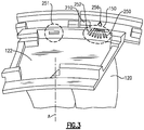
- Figure 3 schematically illustrates a top view of the vane 120 of Figure 2 in one example.
- the vane 120 includes a plenum 122 into which cooling air is directed.
- the cooling air passes through openings 150 in a retention hook 210 on one axial side, relative to an axis of the engine 20.
- the cooling air is passed through the downstream retention hook 210 through the openings 150.
- a portion of the cooling air is passed through a slot 251 as well.
- the slot 251 does not impart directionality to the air passing through, and is located at a portion of the vane 120 where the directionality is not required.
- Each cooling hole 250 in the set of cooling holes is vectored with a length 252 to cross sectional area ratio that is sufficient to impart directionality on the air passing through the retention hook 210.
- the holes 250 are oriented such that the cooling air converges at an elevated cooling requirement position 256 in the adjacent component. This configuration is referred to as the holes having converging axis because the axis of the vectored cooling holes converge at a single point. By converging the axis of the cooling holes 250 at a single location, the majority of the cooling provided from the cooling air is targeted to the elevated cooling requirement position 256.
- only a subset of the holes 250 include converging axis, and another subset of the holes 250 include aligned axis, or axis that otherwise do not converge.
- cooling slot 251 can be omitted entirely, and all the air is passed to adjacent components through vectored cooling holes 250.
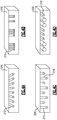
- Figures 4A-4D illustrate different vectored hole 310 configurations.
- the vectored holes 310 have a uniform cross sectional area, with a subset of the holes being aligned, and with the holes not sharing a uniform directionality.
- the cooling air can be split, with a portion being directed to a specific location, and a remainder being directed generally toward the adjacent component.
- Figure 4B illustrates an example where the holes 310 have a triangular cross sectional area, and the holes 310 are not evenly distributed, but are still arranged in a linear configuration.
- Alternative cross sectional shapes can be utilized, with the particular cross sectional shape being selected by a designer based on the available practical manufacturing techniques and the specific needs of a given component.
- Figure 4C illustrates an example where the hole 310 cross sectional area is uniform across the length of the retaining feature 320, however the holes are positioned at distinct radial heights on the retaining feature 320. Placing the holes in a configuration other than linear allows for further control over the directionality and targeted cooling locations of the adjacent component.
- Figure 4D illustrates an example where the cross sectional areas of the holes 310 are not uniform, but the holes 310 are aligned in a linear fashion.
- the utilization of distinct cross sectional areas allows the volume of air targeted at a given location to be more easily controlled, but is constrained by the above described length to cross sectional area ratio required to impart directionality on the airflow.
Landscapes
- Engineering & Computer Science (AREA)
- Mechanical Engineering (AREA)
- General Engineering & Computer Science (AREA)
- Turbine Rotor Nozzle Sealing (AREA)
Applications Claiming Priority (1)
| Application Number | Priority Date | Filing Date | Title |
|---|---|---|---|
| US16/702,887 US11415020B2 (en) | 2019-12-04 | 2019-12-04 | Gas turbine engine flowpath component including vectored cooling flow holes |
Publications (2)
| Publication Number | Publication Date |
|---|---|
| EP3832071A1 true EP3832071A1 (de) | 2021-06-09 |
| EP3832071B1 EP3832071B1 (de) | 2024-04-10 |
Family
ID=73654687
Family Applications (1)
| Application Number | Title | Priority Date | Filing Date |
|---|---|---|---|
| EP20210931.0A Active EP3832071B1 (de) | 2019-12-04 | 2020-12-01 | Strömungspfadkomponente einer gasturbine mit vektorisierten kühlströmungslöchern |
Country Status (2)
| Country | Link |
|---|---|
| US (1) | US11415020B2 (de) |
| EP (1) | EP3832071B1 (de) |
Citations (5)
| Publication number | Priority date | Publication date | Assignee | Title |
|---|---|---|---|---|
| US20050100437A1 (en) * | 2003-11-10 | 2005-05-12 | General Electric Company | Cooling system for nozzle segment platform edges |
| US20060123794A1 (en) * | 2004-12-10 | 2006-06-15 | Pratt & Whitney Canada Corp. | Shroud leading edge cooling |
| US20080131260A1 (en) * | 2006-11-30 | 2008-06-05 | Ching-Pang Lee | Method and system to facilitate cooling turbine engines |
| EP3396112A2 (de) * | 2017-04-25 | 2018-10-31 | United Technologies Corporation | Kühlkanäle einer tragflächenplattform |
| EP3412869A1 (de) * | 2017-06-07 | 2018-12-12 | General Electric Company | Turbomaschinenrotorschaufel |
Family Cites Families (4)
| Publication number | Priority date | Publication date | Assignee | Title |
|---|---|---|---|---|
| US4311431A (en) | 1978-11-08 | 1982-01-19 | Teledyne Industries, Inc. | Turbine engine with shroud cooling means |
| FR2519374B1 (fr) | 1982-01-07 | 1986-01-24 | Snecma | Dispositif de refroidissement des talons d'aubes mobiles d'une turbine |
| WO2015041806A1 (en) * | 2013-09-18 | 2015-03-26 | United Technologies Corporation | Boas thermal protection |
| FR3074521B1 (fr) * | 2017-12-06 | 2019-11-22 | Safran Aircraft Engines | Secteur de distributeur de turbine pour une turbomachine d'aeronef |
-
2019
- 2019-12-04 US US16/702,887 patent/US11415020B2/en active Active
-
2020
- 2020-12-01 EP EP20210931.0A patent/EP3832071B1/de active Active
Patent Citations (5)
| Publication number | Priority date | Publication date | Assignee | Title |
|---|---|---|---|---|
| US20050100437A1 (en) * | 2003-11-10 | 2005-05-12 | General Electric Company | Cooling system for nozzle segment platform edges |
| US20060123794A1 (en) * | 2004-12-10 | 2006-06-15 | Pratt & Whitney Canada Corp. | Shroud leading edge cooling |
| US20080131260A1 (en) * | 2006-11-30 | 2008-06-05 | Ching-Pang Lee | Method and system to facilitate cooling turbine engines |
| EP3396112A2 (de) * | 2017-04-25 | 2018-10-31 | United Technologies Corporation | Kühlkanäle einer tragflächenplattform |
| EP3412869A1 (de) * | 2017-06-07 | 2018-12-12 | General Electric Company | Turbomaschinenrotorschaufel |
Also Published As
| Publication number | Publication date |
|---|---|
| US11415020B2 (en) | 2022-08-16 |
| EP3832071B1 (de) | 2024-04-10 |
| US20210172335A1 (en) | 2021-06-10 |
Similar Documents
| Publication | Publication Date | Title |
|---|---|---|
| EP3039264B1 (de) | Gasturbinenmotordiffusorkühl- und -mischanordnung | |
| US10947853B2 (en) | Gas turbine component with platform cooling | |
| US20200200027A1 (en) | Multiple injector holes for gas turbine engine vane | |
| EP3054138B1 (de) | Turboverdichter mit getriebefan | |
| EP3111057B1 (de) | Zugstangenverbindung für einen mittelturbinenrahmen | |
| US10107122B2 (en) | Variable vane overlap shroud | |
| US20160326884A1 (en) | Axial skin core cooling passage for a turbine engine component | |
| US20150292358A1 (en) | Gas turbine engine inner case including non-symmetrical bleed slots | |
| EP3266983A1 (de) | Kühlsystem für eine schaufel einer gasbetriebenen turbine | |
| EP3330515B1 (de) | Gasturbinenmotor | |
| US20170002662A1 (en) | Gas turbine engine airfoil with bi-axial skin core | |
| EP2904252B2 (de) | Statische leitschaufel mit internen hohlen kanälen | |
| EP3495613B1 (de) | Gekühlte gasturbinenkomponente | |
| US10914192B2 (en) | Impingement cooling for gas turbine engine component | |
| US20160312654A1 (en) | Turbine airfoil cooling | |
| EP3450686A1 (de) | Turbinenschaufel-cluster mit verbesserter plattformkühlung | |
| EP3832071B1 (de) | Strömungspfadkomponente einer gasturbine mit vektorisierten kühlströmungslöchern | |
| US10302014B2 (en) | Modifying a gas turbine engine to use a high pressure compressor as a low pressure compressor | |
| US20160169001A1 (en) | Diffused platform cooling holes | |
| US10954796B2 (en) | Rotor bore conditioning for a gas turbine engine | |
| US20210095596A1 (en) | Multi-flow cooling circuit for gas turbine engine flowpath component | |
| EP3907373B1 (de) | Kühllochkombination für turbinenschaufel | |
| US20200149474A1 (en) | Internal heat exchanger system to cool gas turbine engine components | |
| EP3392472A1 (de) | Verdichterteil für einen gasturbinenmotor sowie zugehöriger gasturbinenmtor und verfahren zum betrieb eines verdichterteils in einem gasturbinenmotor |
Legal Events
| Date | Code | Title | Description |
|---|---|---|---|
| PUAI | Public reference made under article 153(3) epc to a published international application that has entered the european phase |
Free format text: ORIGINAL CODE: 0009012 |
|
| STAA | Information on the status of an ep patent application or granted ep patent |
Free format text: STATUS: THE APPLICATION HAS BEEN PUBLISHED |
|
| AK | Designated contracting states |
Kind code of ref document: A1 Designated state(s): AL AT BE BG CH CY CZ DE DK EE ES FI FR GB GR HR HU IE IS IT LI LT LU LV MC MK MT NL NO PL PT RO RS SE SI SK SM TR |
|
| STAA | Information on the status of an ep patent application or granted ep patent |
Free format text: STATUS: REQUEST FOR EXAMINATION WAS MADE |
|
| 17P | Request for examination filed |
Effective date: 20211208 |
|
| RBV | Designated contracting states (corrected) |
Designated state(s): AL AT BE BG CH CY CZ DE DK EE ES FI FR GB GR HR HU IE IS IT LI LT LU LV MC MK MT NL NO PL PT RO RS SE SI SK SM TR |
|
| RIC1 | Information provided on ipc code assigned before grant |
Ipc: F01D 5/18 20060101AFI20230411BHEP |
|
| GRAP | Despatch of communication of intention to grant a patent |
Free format text: ORIGINAL CODE: EPIDOSNIGR1 |
|
| STAA | Information on the status of an ep patent application or granted ep patent |
Free format text: STATUS: GRANT OF PATENT IS INTENDED |
|
| INTG | Intention to grant announced |
Effective date: 20230623 |
|
| RIN1 | Information on inventor provided before grant (corrected) |
Inventor name: PELLETIER, BRIAN R. Inventor name: VU, KY H. |
|
| RAP3 | Party data changed (applicant data changed or rights of an application transferred) |
Owner name: RTX CORPORATION |
|
| GRAJ | Information related to disapproval of communication of intention to grant by the applicant or resumption of examination proceedings by the epo deleted |
Free format text: ORIGINAL CODE: EPIDOSDIGR1 |
|
| STAA | Information on the status of an ep patent application or granted ep patent |
Free format text: STATUS: REQUEST FOR EXAMINATION WAS MADE |
|
| INTC | Intention to grant announced (deleted) | ||
| GRAP | Despatch of communication of intention to grant a patent |
Free format text: ORIGINAL CODE: EPIDOSNIGR1 |
|
| STAA | Information on the status of an ep patent application or granted ep patent |
Free format text: STATUS: GRANT OF PATENT IS INTENDED |
|
| INTG | Intention to grant announced |
Effective date: 20231222 |
|
| GRAS | Grant fee paid |
Free format text: ORIGINAL CODE: EPIDOSNIGR3 |
|
| GRAA | (expected) grant |
Free format text: ORIGINAL CODE: 0009210 |
|
| STAA | Information on the status of an ep patent application or granted ep patent |
Free format text: STATUS: THE PATENT HAS BEEN GRANTED |
|
| AK | Designated contracting states |
Kind code of ref document: B1 Designated state(s): AL AT BE BG CH CY CZ DE DK EE ES FI FR GB GR HR HU IE IS IT LI LT LU LV MC MK MT NL NO PL PT RO RS SE SI SK SM TR |
|
| REG | Reference to a national code |
Ref country code: GB Ref legal event code: FG4D |
|
| REG | Reference to a national code |
Ref country code: CH Ref legal event code: EP |
|
| REG | Reference to a national code |
Ref country code: DE Ref legal event code: R096 Ref document number: 602020028674 Country of ref document: DE |
|
| REG | Reference to a national code |
Ref country code: IE Ref legal event code: FG4D |
|
| REG | Reference to a national code |
Ref country code: LT Ref legal event code: MG9D |
|
| REG | Reference to a national code |
Ref country code: NL Ref legal event code: MP Effective date: 20240410 |
|
| REG | Reference to a national code |
Ref country code: AT Ref legal event code: MK05 Ref document number: 1675099 Country of ref document: AT Kind code of ref document: T Effective date: 20240410 |
|
| PG25 | Lapsed in a contracting state [announced via postgrant information from national office to epo] |
Ref country code: NL Free format text: LAPSE BECAUSE OF FAILURE TO SUBMIT A TRANSLATION OF THE DESCRIPTION OR TO PAY THE FEE WITHIN THE PRESCRIBED TIME-LIMIT Effective date: 20240410 |
|
| PG25 | Lapsed in a contracting state [announced via postgrant information from national office to epo] |
Ref country code: NL Free format text: LAPSE BECAUSE OF FAILURE TO SUBMIT A TRANSLATION OF THE DESCRIPTION OR TO PAY THE FEE WITHIN THE PRESCRIBED TIME-LIMIT Effective date: 20240410 |
|
| PG25 | Lapsed in a contracting state [announced via postgrant information from national office to epo] |
Ref country code: IS Free format text: LAPSE BECAUSE OF FAILURE TO SUBMIT A TRANSLATION OF THE DESCRIPTION OR TO PAY THE FEE WITHIN THE PRESCRIBED TIME-LIMIT Effective date: 20240810 |
|
| PG25 | Lapsed in a contracting state [announced via postgrant information from national office to epo] |
Ref country code: BG Free format text: LAPSE BECAUSE OF FAILURE TO SUBMIT A TRANSLATION OF THE DESCRIPTION OR TO PAY THE FEE WITHIN THE PRESCRIBED TIME-LIMIT Effective date: 20240410 |
|
| PG25 | Lapsed in a contracting state [announced via postgrant information from national office to epo] |
Ref country code: HR Free format text: LAPSE BECAUSE OF FAILURE TO SUBMIT A TRANSLATION OF THE DESCRIPTION OR TO PAY THE FEE WITHIN THE PRESCRIBED TIME-LIMIT Effective date: 20240410 Ref country code: FI Free format text: LAPSE BECAUSE OF FAILURE TO SUBMIT A TRANSLATION OF THE DESCRIPTION OR TO PAY THE FEE WITHIN THE PRESCRIBED TIME-LIMIT Effective date: 20240410 |
|
| PG25 | Lapsed in a contracting state [announced via postgrant information from national office to epo] |
Ref country code: GR Free format text: LAPSE BECAUSE OF FAILURE TO SUBMIT A TRANSLATION OF THE DESCRIPTION OR TO PAY THE FEE WITHIN THE PRESCRIBED TIME-LIMIT Effective date: 20240711 |
|
| PG25 | Lapsed in a contracting state [announced via postgrant information from national office to epo] |
Ref country code: PT Free format text: LAPSE BECAUSE OF FAILURE TO SUBMIT A TRANSLATION OF THE DESCRIPTION OR TO PAY THE FEE WITHIN THE PRESCRIBED TIME-LIMIT Effective date: 20240812 |
|
| PG25 | Lapsed in a contracting state [announced via postgrant information from national office to epo] |
Ref country code: ES Free format text: LAPSE BECAUSE OF FAILURE TO SUBMIT A TRANSLATION OF THE DESCRIPTION OR TO PAY THE FEE WITHIN THE PRESCRIBED TIME-LIMIT Effective date: 20240410 |
|
| PG25 | Lapsed in a contracting state [announced via postgrant information from national office to epo] |
Ref country code: AT Free format text: LAPSE BECAUSE OF FAILURE TO SUBMIT A TRANSLATION OF THE DESCRIPTION OR TO PAY THE FEE WITHIN THE PRESCRIBED TIME-LIMIT Effective date: 20240410 |
|
| PG25 | Lapsed in a contracting state [announced via postgrant information from national office to epo] |
Ref country code: PL Free format text: LAPSE BECAUSE OF FAILURE TO SUBMIT A TRANSLATION OF THE DESCRIPTION OR TO PAY THE FEE WITHIN THE PRESCRIBED TIME-LIMIT Effective date: 20240410 |
|
| PG25 | Lapsed in a contracting state [announced via postgrant information from national office to epo] |
Ref country code: LV Free format text: LAPSE BECAUSE OF FAILURE TO SUBMIT A TRANSLATION OF THE DESCRIPTION OR TO PAY THE FEE WITHIN THE PRESCRIBED TIME-LIMIT Effective date: 20240410 |
|
| PG25 | Lapsed in a contracting state [announced via postgrant information from national office to epo] |
Ref country code: PT Free format text: LAPSE BECAUSE OF FAILURE TO SUBMIT A TRANSLATION OF THE DESCRIPTION OR TO PAY THE FEE WITHIN THE PRESCRIBED TIME-LIMIT Effective date: 20240812 Ref country code: PL Free format text: LAPSE BECAUSE OF FAILURE TO SUBMIT A TRANSLATION OF THE DESCRIPTION OR TO PAY THE FEE WITHIN THE PRESCRIBED TIME-LIMIT Effective date: 20240410 Ref country code: NO Free format text: LAPSE BECAUSE OF FAILURE TO SUBMIT A TRANSLATION OF THE DESCRIPTION OR TO PAY THE FEE WITHIN THE PRESCRIBED TIME-LIMIT Effective date: 20240710 Ref country code: LV Free format text: LAPSE BECAUSE OF FAILURE TO SUBMIT A TRANSLATION OF THE DESCRIPTION OR TO PAY THE FEE WITHIN THE PRESCRIBED TIME-LIMIT Effective date: 20240410 Ref country code: IS Free format text: LAPSE BECAUSE OF FAILURE TO SUBMIT A TRANSLATION OF THE DESCRIPTION OR TO PAY THE FEE WITHIN THE PRESCRIBED TIME-LIMIT Effective date: 20240810 Ref country code: HR Free format text: LAPSE BECAUSE OF FAILURE TO SUBMIT A TRANSLATION OF THE DESCRIPTION OR TO PAY THE FEE WITHIN THE PRESCRIBED TIME-LIMIT Effective date: 20240410 Ref country code: GR Free format text: LAPSE BECAUSE OF FAILURE TO SUBMIT A TRANSLATION OF THE DESCRIPTION OR TO PAY THE FEE WITHIN THE PRESCRIBED TIME-LIMIT Effective date: 20240711 Ref country code: FI Free format text: LAPSE BECAUSE OF FAILURE TO SUBMIT A TRANSLATION OF THE DESCRIPTION OR TO PAY THE FEE WITHIN THE PRESCRIBED TIME-LIMIT Effective date: 20240410 Ref country code: ES Free format text: LAPSE BECAUSE OF FAILURE TO SUBMIT A TRANSLATION OF THE DESCRIPTION OR TO PAY THE FEE WITHIN THE PRESCRIBED TIME-LIMIT Effective date: 20240410 Ref country code: BG Free format text: LAPSE BECAUSE OF FAILURE TO SUBMIT A TRANSLATION OF THE DESCRIPTION OR TO PAY THE FEE WITHIN THE PRESCRIBED TIME-LIMIT Effective date: 20240410 Ref country code: AT Free format text: LAPSE BECAUSE OF FAILURE TO SUBMIT A TRANSLATION OF THE DESCRIPTION OR TO PAY THE FEE WITHIN THE PRESCRIBED TIME-LIMIT Effective date: 20240410 Ref country code: RS Free format text: LAPSE BECAUSE OF FAILURE TO SUBMIT A TRANSLATION OF THE DESCRIPTION OR TO PAY THE FEE WITHIN THE PRESCRIBED TIME-LIMIT Effective date: 20240710 |
|
| REG | Reference to a national code |
Ref country code: DE Ref legal event code: R097 Ref document number: 602020028674 Country of ref document: DE |
|
| PG25 | Lapsed in a contracting state [announced via postgrant information from national office to epo] |
Ref country code: DK Free format text: LAPSE BECAUSE OF FAILURE TO SUBMIT A TRANSLATION OF THE DESCRIPTION OR TO PAY THE FEE WITHIN THE PRESCRIBED TIME-LIMIT Effective date: 20240410 |
|
| PG25 | Lapsed in a contracting state [announced via postgrant information from national office to epo] |
Ref country code: EE Free format text: LAPSE BECAUSE OF FAILURE TO SUBMIT A TRANSLATION OF THE DESCRIPTION OR TO PAY THE FEE WITHIN THE PRESCRIBED TIME-LIMIT Effective date: 20240410 |
|
| PG25 | Lapsed in a contracting state [announced via postgrant information from national office to epo] |
Ref country code: CZ Free format text: LAPSE BECAUSE OF FAILURE TO SUBMIT A TRANSLATION OF THE DESCRIPTION OR TO PAY THE FEE WITHIN THE PRESCRIBED TIME-LIMIT Effective date: 20240410 |
|
| PG25 | Lapsed in a contracting state [announced via postgrant information from national office to epo] |
Ref country code: RO Free format text: LAPSE BECAUSE OF FAILURE TO SUBMIT A TRANSLATION OF THE DESCRIPTION OR TO PAY THE FEE WITHIN THE PRESCRIBED TIME-LIMIT Effective date: 20240410 Ref country code: SK Free format text: LAPSE BECAUSE OF FAILURE TO SUBMIT A TRANSLATION OF THE DESCRIPTION OR TO PAY THE FEE WITHIN THE PRESCRIBED TIME-LIMIT Effective date: 20240410 |
|
| PG25 | Lapsed in a contracting state [announced via postgrant information from national office to epo] |
Ref country code: SM Free format text: LAPSE BECAUSE OF FAILURE TO SUBMIT A TRANSLATION OF THE DESCRIPTION OR TO PAY THE FEE WITHIN THE PRESCRIBED TIME-LIMIT Effective date: 20240410 |
|
| PG25 | Lapsed in a contracting state [announced via postgrant information from national office to epo] |
Ref country code: SM Free format text: LAPSE BECAUSE OF FAILURE TO SUBMIT A TRANSLATION OF THE DESCRIPTION OR TO PAY THE FEE WITHIN THE PRESCRIBED TIME-LIMIT Effective date: 20240410 Ref country code: SK Free format text: LAPSE BECAUSE OF FAILURE TO SUBMIT A TRANSLATION OF THE DESCRIPTION OR TO PAY THE FEE WITHIN THE PRESCRIBED TIME-LIMIT Effective date: 20240410 Ref country code: RO Free format text: LAPSE BECAUSE OF FAILURE TO SUBMIT A TRANSLATION OF THE DESCRIPTION OR TO PAY THE FEE WITHIN THE PRESCRIBED TIME-LIMIT Effective date: 20240410 Ref country code: EE Free format text: LAPSE BECAUSE OF FAILURE TO SUBMIT A TRANSLATION OF THE DESCRIPTION OR TO PAY THE FEE WITHIN THE PRESCRIBED TIME-LIMIT Effective date: 20240410 Ref country code: DK Free format text: LAPSE BECAUSE OF FAILURE TO SUBMIT A TRANSLATION OF THE DESCRIPTION OR TO PAY THE FEE WITHIN THE PRESCRIBED TIME-LIMIT Effective date: 20240410 Ref country code: CZ Free format text: LAPSE BECAUSE OF FAILURE TO SUBMIT A TRANSLATION OF THE DESCRIPTION OR TO PAY THE FEE WITHIN THE PRESCRIBED TIME-LIMIT Effective date: 20240410 |
|
| PG25 | Lapsed in a contracting state [announced via postgrant information from national office to epo] |
Ref country code: IT Free format text: LAPSE BECAUSE OF FAILURE TO SUBMIT A TRANSLATION OF THE DESCRIPTION OR TO PAY THE FEE WITHIN THE PRESCRIBED TIME-LIMIT Effective date: 20240410 |
|
| PLBE | No opposition filed within time limit |
Free format text: ORIGINAL CODE: 0009261 |
|
| STAA | Information on the status of an ep patent application or granted ep patent |
Free format text: STATUS: NO OPPOSITION FILED WITHIN TIME LIMIT |
|
| 26N | No opposition filed |
Effective date: 20250113 |
|
| PG25 | Lapsed in a contracting state [announced via postgrant information from national office to epo] |
Ref country code: SI Free format text: LAPSE BECAUSE OF FAILURE TO SUBMIT A TRANSLATION OF THE DESCRIPTION OR TO PAY THE FEE WITHIN THE PRESCRIBED TIME-LIMIT Effective date: 20240410 |
|
| PG25 | Lapsed in a contracting state [announced via postgrant information from national office to epo] |
Ref country code: MC Free format text: LAPSE BECAUSE OF FAILURE TO SUBMIT A TRANSLATION OF THE DESCRIPTION OR TO PAY THE FEE WITHIN THE PRESCRIBED TIME-LIMIT Effective date: 20240410 |
|
| REG | Reference to a national code |
Ref country code: CH Ref legal event code: PL |
|
| PG25 | Lapsed in a contracting state [announced via postgrant information from national office to epo] |
Ref country code: LU Free format text: LAPSE BECAUSE OF NON-PAYMENT OF DUE FEES Effective date: 20241201 |
|
| PG25 | Lapsed in a contracting state [announced via postgrant information from national office to epo] |
Ref country code: SE Free format text: LAPSE BECAUSE OF FAILURE TO SUBMIT A TRANSLATION OF THE DESCRIPTION OR TO PAY THE FEE WITHIN THE PRESCRIBED TIME-LIMIT Effective date: 20240410 |
|
| REG | Reference to a national code |
Ref country code: BE Ref legal event code: MM Effective date: 20241231 |
|
| PG25 | Lapsed in a contracting state [announced via postgrant information from national office to epo] |
Ref country code: BE Free format text: LAPSE BECAUSE OF NON-PAYMENT OF DUE FEES Effective date: 20241231 |
|
| PG25 | Lapsed in a contracting state [announced via postgrant information from national office to epo] |
Ref country code: CH Free format text: LAPSE BECAUSE OF NON-PAYMENT OF DUE FEES Effective date: 20241231 |
|
| PG25 | Lapsed in a contracting state [announced via postgrant information from national office to epo] |
Ref country code: IE Free format text: LAPSE BECAUSE OF NON-PAYMENT OF DUE FEES Effective date: 20241201 |
|
| PGFP | Annual fee paid to national office [announced via postgrant information from national office to epo] |
Ref country code: DE Payment date: 20251126 Year of fee payment: 6 |
|
| PGFP | Annual fee paid to national office [announced via postgrant information from national office to epo] |
Ref country code: GB Payment date: 20251120 Year of fee payment: 6 |
|
| PGFP | Annual fee paid to national office [announced via postgrant information from national office to epo] |
Ref country code: FR Payment date: 20251120 Year of fee payment: 6 |