EP3832070B1 - Impingement insert for a hot gas path component and hot gas path component - Google Patents
Impingement insert for a hot gas path component and hot gas path component Download PDFInfo
- Publication number
- EP3832070B1 EP3832070B1 EP20208776.3A EP20208776A EP3832070B1 EP 3832070 B1 EP3832070 B1 EP 3832070B1 EP 20208776 A EP20208776 A EP 20208776A EP 3832070 B1 EP3832070 B1 EP 3832070B1
- Authority
- EP
- European Patent Office
- Prior art keywords
- side wall
- hollow body
- impingement insert
- component
- spring element
- Prior art date
- Legal status (The legal status is an assumption and is not a legal conclusion. Google has not performed a legal analysis and makes no representation as to the accuracy of the status listed.)
- Active
Links
Images




Classifications
-
- F—MECHANICAL ENGINEERING; LIGHTING; HEATING; WEAPONS; BLASTING
- F01—MACHINES OR ENGINES IN GENERAL; ENGINE PLANTS IN GENERAL; STEAM ENGINES
- F01D—NON-POSITIVE DISPLACEMENT MACHINES OR ENGINES, e.g. STEAM TURBINES
- F01D5/00—Blades; Blade-carrying members; Heating, heat-insulating, cooling or antivibration means on the blades or the members
- F01D5/12—Blades
- F01D5/14—Form or construction
- F01D5/18—Hollow blades, i.e. blades with cooling or heating channels or cavities; Heating, heat-insulating or cooling means on blades
- F01D5/187—Convection cooling
- F01D5/188—Convection cooling with an insert in the blade cavity to guide the cooling fluid, e.g. forming a separation wall
-
- F—MECHANICAL ENGINEERING; LIGHTING; HEATING; WEAPONS; BLASTING
- F02—COMBUSTION ENGINES; HOT-GAS OR COMBUSTION-PRODUCT ENGINE PLANTS
- F02C—GAS-TURBINE PLANTS; AIR INTAKES FOR JET-PROPULSION PLANTS; CONTROLLING FUEL SUPPLY IN AIR-BREATHING JET-PROPULSION PLANTS
- F02C7/00—Features, components parts, details or accessories, not provided for in, or of interest apart form groups F02C1/00 - F02C6/00; Air intakes for jet-propulsion plants
- F02C7/12—Cooling of plants
- F02C7/16—Cooling of plants characterised by cooling medium
- F02C7/18—Cooling of plants characterised by cooling medium the medium being gaseous, e.g. air
-
- F—MECHANICAL ENGINEERING; LIGHTING; HEATING; WEAPONS; BLASTING
- F01—MACHINES OR ENGINES IN GENERAL; ENGINE PLANTS IN GENERAL; STEAM ENGINES
- F01D—NON-POSITIVE DISPLACEMENT MACHINES OR ENGINES, e.g. STEAM TURBINES
- F01D9/00—Stators
- F01D9/06—Fluid supply conduits to nozzles or the like
- F01D9/065—Fluid supply or removal conduits traversing the working fluid flow, e.g. for lubrication-, cooling-, or sealing fluids
-
- F—MECHANICAL ENGINEERING; LIGHTING; HEATING; WEAPONS; BLASTING
- F01—MACHINES OR ENGINES IN GENERAL; ENGINE PLANTS IN GENERAL; STEAM ENGINES
- F01D—NON-POSITIVE DISPLACEMENT MACHINES OR ENGINES, e.g. STEAM TURBINES
- F01D5/00—Blades; Blade-carrying members; Heating, heat-insulating, cooling or antivibration means on the blades or the members
- F01D5/12—Blades
- F01D5/14—Form or construction
- F01D5/18—Hollow blades, i.e. blades with cooling or heating channels or cavities; Heating, heat-insulating or cooling means on blades
- F01D5/187—Convection cooling
- F01D5/188—Convection cooling with an insert in the blade cavity to guide the cooling fluid, e.g. forming a separation wall
- F01D5/189—Convection cooling with an insert in the blade cavity to guide the cooling fluid, e.g. forming a separation wall the insert having a tubular cross-section, e.g. airfoil shape
-
- B—PERFORMING OPERATIONS; TRANSPORTING
- B22—CASTING; POWDER METALLURGY
- B22F—WORKING METALLIC POWDER; MANUFACTURE OF ARTICLES FROM METALLIC POWDER; MAKING METALLIC POWDER; APPARATUS OR DEVICES SPECIALLY ADAPTED FOR METALLIC POWDER
- B22F5/00—Manufacture of workpieces or articles from metallic powder characterised by the special shape of the product
- B22F5/009—Manufacture of workpieces or articles from metallic powder characterised by the special shape of the product of turbine components other than turbine blades
-
- B—PERFORMING OPERATIONS; TRANSPORTING
- B22—CASTING; POWDER METALLURGY
- B22F—WORKING METALLIC POWDER; MANUFACTURE OF ARTICLES FROM METALLIC POWDER; MAKING METALLIC POWDER; APPARATUS OR DEVICES SPECIALLY ADAPTED FOR METALLIC POWDER
- B22F5/00—Manufacture of workpieces or articles from metallic powder characterised by the special shape of the product
- B22F5/04—Manufacture of workpieces or articles from metallic powder characterised by the special shape of the product of turbine blades
-
- B—PERFORMING OPERATIONS; TRANSPORTING
- B33—ADDITIVE MANUFACTURING TECHNOLOGY
- B33Y—ADDITIVE MANUFACTURING, i.e. MANUFACTURING OF THREE-DIMENSIONAL [3D] OBJECTS BY ADDITIVE DEPOSITION, ADDITIVE AGGLOMERATION OR ADDITIVE LAYERING, e.g. BY 3D PRINTING, STEREOLITHOGRAPHY OR SELECTIVE LASER SINTERING
- B33Y80/00—Products made by additive manufacturing
-
- F—MECHANICAL ENGINEERING; LIGHTING; HEATING; WEAPONS; BLASTING
- F05—INDEXING SCHEMES RELATING TO ENGINES OR PUMPS IN VARIOUS SUBCLASSES OF CLASSES F01-F04
- F05D—INDEXING SCHEME FOR ASPECTS RELATING TO NON-POSITIVE-DISPLACEMENT MACHINES OR ENGINES, GAS-TURBINES OR JET-PROPULSION PLANTS
- F05D2230/00—Manufacture
- F05D2230/20—Manufacture essentially without removing material
- F05D2230/22—Manufacture essentially without removing material by sintering
-
- F—MECHANICAL ENGINEERING; LIGHTING; HEATING; WEAPONS; BLASTING
- F05—INDEXING SCHEMES RELATING TO ENGINES OR PUMPS IN VARIOUS SUBCLASSES OF CLASSES F01-F04
- F05D—INDEXING SCHEME FOR ASPECTS RELATING TO NON-POSITIVE-DISPLACEMENT MACHINES OR ENGINES, GAS-TURBINES OR JET-PROPULSION PLANTS
- F05D2230/00—Manufacture
- F05D2230/20—Manufacture essentially without removing material
- F05D2230/23—Manufacture essentially without removing material by permanently joining parts together
- F05D2230/232—Manufacture essentially without removing material by permanently joining parts together by welding
- F05D2230/234—Laser welding
-
- F—MECHANICAL ENGINEERING; LIGHTING; HEATING; WEAPONS; BLASTING
- F05—INDEXING SCHEMES RELATING TO ENGINES OR PUMPS IN VARIOUS SUBCLASSES OF CLASSES F01-F04
- F05D—INDEXING SCHEME FOR ASPECTS RELATING TO NON-POSITIVE-DISPLACEMENT MACHINES OR ENGINES, GAS-TURBINES OR JET-PROPULSION PLANTS
- F05D2230/00—Manufacture
- F05D2230/30—Manufacture with deposition of material
- F05D2230/31—Layer deposition
-
- F—MECHANICAL ENGINEERING; LIGHTING; HEATING; WEAPONS; BLASTING
- F05—INDEXING SCHEMES RELATING TO ENGINES OR PUMPS IN VARIOUS SUBCLASSES OF CLASSES F01-F04
- F05D—INDEXING SCHEME FOR ASPECTS RELATING TO NON-POSITIVE-DISPLACEMENT MACHINES OR ENGINES, GAS-TURBINES OR JET-PROPULSION PLANTS
- F05D2230/00—Manufacture
- F05D2230/50—Building or constructing in particular ways
- F05D2230/51—Building or constructing in particular ways in a modular way, e.g. using several identical or complementary parts or features
-
- F—MECHANICAL ENGINEERING; LIGHTING; HEATING; WEAPONS; BLASTING
- F05—INDEXING SCHEMES RELATING TO ENGINES OR PUMPS IN VARIOUS SUBCLASSES OF CLASSES F01-F04
- F05D—INDEXING SCHEME FOR ASPECTS RELATING TO NON-POSITIVE-DISPLACEMENT MACHINES OR ENGINES, GAS-TURBINES OR JET-PROPULSION PLANTS
- F05D2230/00—Manufacture
- F05D2230/50—Building or constructing in particular ways
- F05D2230/54—Building or constructing in particular ways by sheet metal manufacturing
-
- F—MECHANICAL ENGINEERING; LIGHTING; HEATING; WEAPONS; BLASTING
- F05—INDEXING SCHEMES RELATING TO ENGINES OR PUMPS IN VARIOUS SUBCLASSES OF CLASSES F01-F04
- F05D—INDEXING SCHEME FOR ASPECTS RELATING TO NON-POSITIVE-DISPLACEMENT MACHINES OR ENGINES, GAS-TURBINES OR JET-PROPULSION PLANTS
- F05D2250/00—Geometry
- F05D2250/10—Two-dimensional
- F05D2250/11—Two-dimensional triangular
-
- F—MECHANICAL ENGINEERING; LIGHTING; HEATING; WEAPONS; BLASTING
- F05—INDEXING SCHEMES RELATING TO ENGINES OR PUMPS IN VARIOUS SUBCLASSES OF CLASSES F01-F04
- F05D—INDEXING SCHEME FOR ASPECTS RELATING TO NON-POSITIVE-DISPLACEMENT MACHINES OR ENGINES, GAS-TURBINES OR JET-PROPULSION PLANTS
- F05D2250/00—Geometry
- F05D2250/10—Two-dimensional
- F05D2250/18—Two-dimensional patterned
- F05D2250/182—Two-dimensional patterned crenellated, notched
-
- F—MECHANICAL ENGINEERING; LIGHTING; HEATING; WEAPONS; BLASTING
- F05—INDEXING SCHEMES RELATING TO ENGINES OR PUMPS IN VARIOUS SUBCLASSES OF CLASSES F01-F04
- F05D—INDEXING SCHEME FOR ASPECTS RELATING TO NON-POSITIVE-DISPLACEMENT MACHINES OR ENGINES, GAS-TURBINES OR JET-PROPULSION PLANTS
- F05D2250/00—Geometry
- F05D2250/10—Two-dimensional
- F05D2250/18—Two-dimensional patterned
- F05D2250/183—Two-dimensional patterned zigzag
-
- F—MECHANICAL ENGINEERING; LIGHTING; HEATING; WEAPONS; BLASTING
- F05—INDEXING SCHEMES RELATING TO ENGINES OR PUMPS IN VARIOUS SUBCLASSES OF CLASSES F01-F04
- F05D—INDEXING SCHEME FOR ASPECTS RELATING TO NON-POSITIVE-DISPLACEMENT MACHINES OR ENGINES, GAS-TURBINES OR JET-PROPULSION PLANTS
- F05D2250/00—Geometry
- F05D2250/10—Two-dimensional
- F05D2250/18—Two-dimensional patterned
- F05D2250/184—Two-dimensional patterned sinusoidal
-
- F—MECHANICAL ENGINEERING; LIGHTING; HEATING; WEAPONS; BLASTING
- F05—INDEXING SCHEMES RELATING TO ENGINES OR PUMPS IN VARIOUS SUBCLASSES OF CLASSES F01-F04
- F05D—INDEXING SCHEME FOR ASPECTS RELATING TO NON-POSITIVE-DISPLACEMENT MACHINES OR ENGINES, GAS-TURBINES OR JET-PROPULSION PLANTS
- F05D2250/00—Geometry
- F05D2250/20—Three-dimensional
- F05D2250/29—Three-dimensional machined; miscellaneous
- F05D2250/294—Three-dimensional machined; miscellaneous grooved
-
- F—MECHANICAL ENGINEERING; LIGHTING; HEATING; WEAPONS; BLASTING
- F05—INDEXING SCHEMES RELATING TO ENGINES OR PUMPS IN VARIOUS SUBCLASSES OF CLASSES F01-F04
- F05D—INDEXING SCHEME FOR ASPECTS RELATING TO NON-POSITIVE-DISPLACEMENT MACHINES OR ENGINES, GAS-TURBINES OR JET-PROPULSION PLANTS
- F05D2250/00—Geometry
- F05D2250/70—Shape
- F05D2250/75—Shape given by its similarity to a letter, e.g. T-shaped
-
- F—MECHANICAL ENGINEERING; LIGHTING; HEATING; WEAPONS; BLASTING
- F05—INDEXING SCHEMES RELATING TO ENGINES OR PUMPS IN VARIOUS SUBCLASSES OF CLASSES F01-F04
- F05D—INDEXING SCHEME FOR ASPECTS RELATING TO NON-POSITIVE-DISPLACEMENT MACHINES OR ENGINES, GAS-TURBINES OR JET-PROPULSION PLANTS
- F05D2260/00—Function
- F05D2260/20—Heat transfer, e.g. cooling
- F05D2260/201—Heat transfer, e.g. cooling by impingement of a fluid
-
- F—MECHANICAL ENGINEERING; LIGHTING; HEATING; WEAPONS; BLASTING
- F05—INDEXING SCHEMES RELATING TO ENGINES OR PUMPS IN VARIOUS SUBCLASSES OF CLASSES F01-F04
- F05D—INDEXING SCHEME FOR ASPECTS RELATING TO NON-POSITIVE-DISPLACEMENT MACHINES OR ENGINES, GAS-TURBINES OR JET-PROPULSION PLANTS
- F05D2260/00—Function
- F05D2260/30—Retaining components in desired mutual position
- F05D2260/37—Retaining components in desired mutual position by a press fit connection
-
- F—MECHANICAL ENGINEERING; LIGHTING; HEATING; WEAPONS; BLASTING
- F05—INDEXING SCHEMES RELATING TO ENGINES OR PUMPS IN VARIOUS SUBCLASSES OF CLASSES F01-F04
- F05D—INDEXING SCHEME FOR ASPECTS RELATING TO NON-POSITIVE-DISPLACEMENT MACHINES OR ENGINES, GAS-TURBINES OR JET-PROPULSION PLANTS
- F05D2260/00—Function
- F05D2260/30—Retaining components in desired mutual position
- F05D2260/38—Retaining components in desired mutual position by a spring, i.e. spring loaded or biased towards a certain position
Definitions
- the invention relates generally to turbomachinery, and more particularly, to an impingement insert for a hot gas path (HGP) component according to the preamble of independent claim 1.
- the invention also relates to a hot gas path (HGP) component.
- An impingement insert or sleeve includes a hollow body having cooling passages in a wall thereof that allow delivery of a coolant through the cooling passages to impact or impinge on a surface to be cooled.
- Impingement inserts are used in a variety of HGP components in turbomachinery to increase cooling performance of cooling circuitry therein.
- One indicator of cooling performance of an insert is the Z/D parameter, which is a ratio of a distance D between the insert and interior surface of the HGP component and a diameter D of the cooling passages (holes) in the impingement insert.
- the Z/D parameter value of an insert is typically designed to be within a desired range that results in better cooling performance.
- impingement inserts One challenge with impingement inserts is positioning the impingement insert within a cavity in an already formed HGP component, but also positioning the insert in a sufficiently close manner to allow for high cooling performance, i.e., observed by a lower Z/D parameter.
- One approach includes providing the impingement insert in a number of flexible, longitudinal sections to make it easier to insert them into the HGP component.
- having to sequentially position and couple a number of insert sections together or couple them to the HGP component increases the complexity, time and costs of manufacture.
- Flexible impingement insert sections also do not provide a contiguous element about their periphery, i.e., laterally (cross-section), which can detract from cooling performance where they are discontinuous.
- US3 806 275 A discloses an impingement insert formed as a blade liner mounted in a hollow cavity of a turbine blade, the impingement insert having the features of the preamble of independent claim 1.
- the blade liner is open a platform end and closed at the tip of the blade.
- US 5 516 260 A discloses an airfoil of a turbine blade including a radially extending cavity defined by an inner surface which has a plurality ribs and an impingement insert disposed on the inner surface.
- the insert includes a hollow body having a longitudinal extent, a first side wall, a second side wall contiguous with the first side wall at a first end of each, the second side wall configured to be flexibly movable relative to the first side wall, a plurality of cooling passages in the first and second side walls, the plurality of cooling passages passing between the exterior surface and the interior surface of the hollow body, and a spring element formed by a U-shaped fold in the insert and extending along its longitudinal extent of the hollow body and into the hollow body to be between the first side wall and the second side wall.
- the spring element biases the first side wall and the second side wall to an expanded position of the hollow body in abutting sealing contact with the ribs in the cavity from a compressed position of the hollow body.
- a first aspect of the disclosure provides an impingement insert for a hot gas path (HGP) component, the impingement insert comprising: a hollow body having a longitudinal extent, an exterior surface and an interior surface, the hollow body further including: a first side wall, a second side wall contiguous with the first side wall at a first end of each, the second side wall configured to be flexibly movable relative to the first side wall, a closure on a first end of the hollow body, and a spring element contiguous with a second end of each of the first side wall and the second side wall, the spring element extending along at least a portion of the longitudinal extent of the hollow body and into the hollow body to be between the first side wall and the second side wall, the spring element biasing the first side wall and the second side wall to an expanded position of the hollow body from a compressed position of the hollow body; and a plurality of cooling passages in at least the first side wall and the second side wall, the plurality of cooling passages passing between the exterior surface and the interior surface of the hollow body.
- the closure includes a solid portion for closing a first portion of the first end of the hollow body and leaving a second portion of the first end of the hollow body open, wherein an end of the spring element adjacent the first end of the hollow body is free to move within the second portion of the first end of the hollow body not closed by the closure.
- a second aspect of the disclosure provides a hot gas path (HGP) component, comprising a component body having a hollow cavity therein, and an impingement insert as described before, the impingement insert mounted in the hollow cavity of the component body.
- HGP hot gas path
- downstream and upstream are terms that indicate a direction relative to the flow of a fluid, such as the working fluid through the turbine GT system or, for example, the flow of air through the combustor or coolant through one of the turbine's component systems.
- the term “downstream” corresponds to the direction of flow of the fluid, and the term “upstream” refers to the direction opposite to the flow.
- forward and “aft,” without any further specificity, refer to directions, with “forward” referring to the front or compressor end of the GT system, and “aft” referring to the rearward or turbine end of the GT system. It is often required to describe parts that are at differing radial positions with regard to a center axis.
- radial refers to movement or position perpendicular to an axis. In cases such as this, if a first component resides closer to the axis than a second component, it will be stated herein that the first component is “radially inward” or “inboard” of the second component.
- first component resides further from the axis than the second component, it may be stated herein that the first component is “radially outward” or “outboard” of the second component.
- axial refers to movement or position parallel to an axis.
- circumferential refers to movement or position around an axis. It will be appreciated that such terms may be applied in relation to the center axis of the turbine.
- the disclosure provides an impingement insert for an HGP component and an HGP component that includes the impingement insert.
- the impingement insert which may also be referred to as an impingement sleeve, includes a hollow body having a longitudinal extent, an exterior surface and an interior surface.
- the hollow body includes a first side wall and a second side wall contiguous with the first side wall at a first end of each.
- the second side wall is flexibly movable relative to the first side wall.
- a spring element is contiguous with a second end of each of the first side wall and the second side wall, and extends along at least a portion of the longitudinal extent of the hollow body. The spring element also extends into the hollow body between the first side wall and the second side wall.
- the spring element biases the side walls to an expanded position from a compressed position of the hollow body.
- Cooling passages pass between the exterior surface and the interior surface of the hollow body in both side walls.
- the impingement insert is compressible and/or flexible laterally such that it can be compressed, inserted into a hollow cavity in an already formed HGP component, released to fill the shape of the hollow cavity and fixed into position.
- the impingement insert extends an entire length of the hollow cavity in the HGP component, i.e., it is not sectioned, making its insertion a one-step operation. Further, the impingement insert is contiguous laterally, i.e., in a circumferential cross-section, so as to avoid creating areas of poor cooling performance.
- FIG. 1 shows a schematic illustration of an illustrative machine in the form of a turbomachine 90 that includes a hot gas path (HGP) component including an impingement insert according to embodiments of the disclosure.
- turbomachine 90 includes a gas turbine (GT) system 100 that includes a compressor 102 and a combustor 104.
- Combustor 104 includes a combustion region 105 and a fuel nozzle assembly 106.
- GT system 100 also includes a turbine 108 and a common compressor/turbine shaft 110 (sometimes referred to as rotor 110).
- GT system 100 is a MS7001FB GT system, sometimes referred to as a 9FB GT system, commercially available from General Electric Company, Greenville, S.C.
- the present disclosure is not limited to any one particular GT system and may be implanted in connection with other GT systems including, for example, the MS7001FA (7FA) and MS9001FA (9FA) GT system models of General Electric Company.
- the compressed air is supplied to fuel nozzle assembly 106 that is integral to combustor 104.
- Assembly 106 is in flow communication with combustion region 105.
- Fuel nozzle assembly 106 is also in flow communication with a fuel source (not shown in FIG. 1 ) and channels fuel and air to combustion region 105.
- Combustor 104 ignites and combusts fuel.
- Combustor 104 is in flow communication with turbine 108 for which gas stream thermal energy is converted to mechanical rotational energy.
- Turbine 108 is rotatably coupled to and drives rotor 110.
- Compressor 102 also is rotatably coupled to shaft 110.
- FIG. 2 shows a cross-sectional illustration of an illustrative turbine 108 with a three stage nozzle that may be used with GT system 100 in FIG. 1 .
- Turbine 108 includes a stationary vane 112.
- Stationary vane 112 is held in the turbine assembly 108 by a radially outer platform 114 and a radially inner platform 116.
- Stationary vane 112 may include one or more circumferentially spaced airfoils 156 ( FIG. 4 ).
- Rotating blades 120 are coupled to rotor 110 and extend between rows of stationary vanes 112. As will be further described, combustion gases are directed by stationary vanes 112 against rotating blades 120 to turn rotor 110.
- FIGS. 3 and 4 show illustrative HGP components 122 of GT system 100 in which an impingement insert according to embodiments of the disclosure may be employed.
- FIG. 3 shows a perspective view of a turbine rotor blade 130 of the type in which embodiments of the present disclosure may be employed.
- Turbine rotor blade 130 includes a root 132 by which rotor blade 130 attaches to rotor 110 ( FIGS. 1-2 ).
- Root 132 may include a dovetail configured for mounting in a corresponding dovetail slot in the perimeter of the rotor disc.
- Root 132 may further include a shank that extends between the dovetail and a platform 134, which is disposed at the junction of airfoil 136 and root 132 and defines a portion of the inboard boundary of the flow path through turbine 108.
- airfoil 136 is the active component of rotor blade 130 that intercepts the flow of working fluid and induces the rotor disc to rotate.
- airfoil 136 of rotor blade 130 includes a concave pressure side (PS) outer wall 140 and a circumferentially or laterally opposite convex suction side (SS) outer wall 142 extending axially between opposite leading and trailing edges 144, 146 respectively.
- Outer walls 140 and 142 also extend in the radial direction from platform 134 to an outboard tip 148.
- FIG. 4 shows a perspective view of a stationary nozzle or vane 150 of the type in which embodiments of the present disclosure may be employed.
- Stationary vane 150 includes an outer platform 152 by which stationary vane 150 attaches to a casing of the turbomachine.
- Outer platform 152 may include any now known or later developed mounting configuration for mounting in a corresponding mount in the casing.
- Stationary vane 150 may further include an inner platform 154 for positioning between adjacent turbine rotor blades 120, 130 ( FIGS. 2 and 3 ) platforms 134 ( FIG. 3 ). Platforms 152, 154 define respective portions of the outboard and inboard boundary of the flow path through GT system 100.
- airfoil 156 is the active component of stationary vane 150 that intercepts the flow of working fluid and directs it towards turbine rotor blades 130 ( FIG. 3 ). It will be seen that airfoil 156 of stationary vane 150 includes a concave pressure side (PS) outer wall 160 and a circumferentially or laterally opposite convex suction side (SS) outer wall 162 extending axially between opposite leading and trailing edges 164, 166 respectively. Outer walls 160 and 162 also extend in the radial direction from platform 154 to platform 152.
- PS concave pressure side
- SS convex suction side
- an impingement insert is employed in HGP component 122 of, for example, GT system 100, to distribute a cooling fluid to the HGP component.
- HGP component 122 may include, for example, rotating blade 130 or stationary vane 150, and/or airfoils 136, 156 thereof.
- FIG. 5 shows a schematic view of an illustrative HGP component 122 including a hollow cavity 172 in a component body 170 thereof, e.g., in either of airfoils 136, 156 ( FIGS. 3 and 4 ). That is, HGP component 122 includes component body 170 having hollow cavity 172 therein into which an impingement insert 180 is positioned.
- a coolant like air or steam is supplied to an interior of impingement insert 180, and exits through cooling passages (not shown in FIG. 5 ) therein.
- the exiting coolant impinges on an interior surface 184 of HGP component 122 and cools the HGP component.
- HGP component includes an airfoil 136, 156, it may include hollow cavity 172 therein that extends a substantial portion of a length thereof.
- Embodiments of an impingement insert 180 according to embodiments of the disclosure can be applied in hollow cavity 172 in, for example, airfoil(s) 136, 156 ( FIGS. 3 and 4 ).
- hollow body 190 is contiguous in a chordwise direction of the airfoil, i.e., in a circumferential cross-section of the airfoil. While the teachings of the disclosure will be described relative to GT system 100, rotating blades 120, 130 and stationary vanes 112, 150 and airfoils 136, 156 thereof, it is emphasized that the teachings are not limited to only these applications. Impingement inserts 180 according to embodiments of the disclosure can be applied to a wide variety of other applications, all of which are considered within the scope of the disclosure.
- FIGS. 6-8 show various views of an impingement insert 180 according to embodiments of the disclosure.
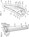
- FIG. 6 shows a perspective view
- FIG. 7 shows a top down view
- FIG. 8 shows a side view of an impingement insert 180 according to embodiments of the disclosure.
- Impingement insert 180 includes a hollow body 190 having a longitudinal extent L ( FIG. 8 only), exterior surface 192 and an interior surface 194. Longitudinal extent L may be any length necessary for operation of the particular impingement insert 180, which depends on its function.
- An impingement insert 180 may have a length L to match that of hollow cavity 172 of component body 170, e.g., in a vane or blade.
- Hollow body 190 also includes a first side wall 200 and a second side wall 202.
- Second side wall 202 is contiguous with first side wall 200 at a first end 204 of each. That is, first and second side wall 200, 202 have no seam or joint therebetween at first end 204.
- first and second side wall 200, 202 are angled relative to one another and may each have a shape to parallel interior surface 184 of hollow cavity 172 of HGP component 122.
- Side walls 200, 202 are configured to be flexibly movable relative to one another.
- Hollow body 190 also includes a spring element 210 contiguous with a second end 212 of each of first side wall 200 and second side wall 202. Second ends 212 of side walls are spaced from one another such that spring element 200 may extend along at least a portion of the longitudinal extent L ( FIG. 6 ) of hollow body 190. In the example shown, spring element 210 extends an entire length of hollow body 190, but this is not necessary in all cases. Spring element 210 also extends into hollow body 190 to be between first side wall 200 and second side wall 202.
- spring element 210 extends between side walls 200, 202, as it extends inwardly into hollow body 190.
- Spring element 210 extending into hollow body 190 between first side wall 200 and second side wall 202 provides a smaller, more compact, footprint for impingement insert and makes it easier to insert into HGP component 122.
- impingement insert 180 also includes a plurality of cooling passages 220 in at least first side wall 200 and second side wall 202. Cooling passages 220 pass between exterior surface 192 and interior surface 194 of hollow body 190. Cooling passages 220 allow coolant to pass from hollow body 190 to impinge interior surface 184 ( FIG. 5 ) of hollow cavity 172 in component body 170 of HGP component 122. Any number, shape, size or arrangement of cooling passages 220 may be provided.
- Spring element 210 biases first side wall 200 and second side wall 202 to an expanded position of hollow body 190, shown in FIGS. 5-8 , 12-14 and 16 , from a compressed position of hollow body 190, shown in FIGS. 11 and 15 .
- Spring element 210 may include any now known or later developed spring capable of withstanding the environment of HGP component 122, and providing sufficient force F2 ( FIG. 12 ) to expand first and second side wall 200, 202.
- spring element 210 includes a V-spring 214 having a point 216 thereof extending into hollow body 190 between first side wall 200 and second side wall 202.
- FIGS. 5-8 , 11-16 spring element 210 includes a V-spring 214 having a point 216 thereof extending into hollow body 190 between first side wall 200 and second side wall 202.
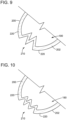
- spring element 210 may have a sinusoidal shape with any number of waves therein, e.g., with two (W-shaped in FIG. 9 ) or more peaks ( FIG. 10 ). Other shapes for spring element 210 may also be possible.
- impingement insert 180 may also include a plurality of supports 224 on exterior surface 192 of first side wall 200 and second side wall 202 of hollow body 190.
- Supports 224 may position hollow body 190 relative to interior surface 184 ( FIG. 5 ) of hollow cavity 172 of HGP component 122, and may assist in heat transfer. Any number of supports 224 operable to position impingement insert 180 relative to interior surface 184 ( FIG. 5 ), or provide the desired heat transfer, can be used.
- Supports 224 can have any desired shape configured to position the insert relative to interior surface 184 ( FIG. 5 ) and/or provide the desired heat transfer, e.g., fins, pins and/or chevrons, etc.
- impingement insert 180 also includes a closure 230 on a first end 232 ( FIGS. 11-12 ) of hollow body 190.
- FIG. 11 shows a cross-sectional view of an end of hollow body 190 in a compressed position
- FIG. 12 shows a cross-sectional view of an end of hollow body 190 in an expanded position.
- closure 230 includes a solid portion 234 for closing a first portion 236 of first end 232 of hollow body 190 and leaving a second portion 238 of first end 232 of hollow body 190 open.
- Closure 230 may be coupled to first end 232 in any now known or later developed manner, e.g., welding, additively manufactured together, etc.
- Closure 230 may be shaped to match a shape of first portion 236 between first side wall 200 and second side wall 202, e.g., partially shaped like a circumferential cross-section of an airfoil.
- Closure 230 may have any shaped edge 240 that defines open second portion 238 with remaining edges of first side wall 200 and second side wall 202.
- edge 240 of closure 230 may be shaped and positioned to allow open second portion 238 to provide sufficient space for spring element 210 movement. In this regard, as shown in FIGS.
- an end 246 of spring element 210 adjacent first end 232 of hollow body 190 is free to move within (open) second portion 238 of first end 232 of hollow body 190 not closed by closure 230, i.e., as spring element 210 moves between the expanded and compressed positions.
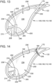
- edge 240 is linear, but for example, in FIG. 13 , edge 240 is V-shaped, and in FIG. 14 , edge 240 is curved.
- FIGS. 11 and 12 illustrate that solid portion 234 of closure 230 may be configured to flex with first side wall 200 and second side wall 202 of hollow body 190 as the side walls move between an expanded position, shown in FIG. 12 , of hollow body 190 and, as shown in FIG.
- solid portion 234 may bow outwardly from hollow body 190 to accommodate the compression, but this may not be necessary in all instances.
- Solid portion 234 may be configured to flex in any now known or later developed manner, e.g., made of flexible metal, formed slightly curved, slotted or otherwise structured to accommodate flexing. Solid portion 234 could also be configured to bow inwardly into hollow body 190. In an expanded position, shown in FIG. 12 , solid portion 234 may be substantially planar.
- Impingement insert 180 may also optionally include any now known or later developed cover 250. Impingement insert 180 can also be devoid of a cover.
- a cover 250 may be provided for connection to interior surface 184 of hollow cavity 172, near an end of the hollow cavity, to seal or reduce flow out of an end of the space between exterior surface 192 ( FIG. 8 ) of hollow body 190 and interior surface 184 ( FIG. 5 ) of hollow cavity 172 of HGP component 122.
- Cover 250 may also act to space impingement insert from interior surface 184 of hollow cavity 172. As shown for example in FIGS. 6 and 8 , cover 250 may extend laterally outward on a second end 252 of hollow body 190 opposing first end 232 ( FIG. 6 ) of hollow body 190.
- Cover 250 is configured to be coupled to HGP component 122, e.g., it has an inner shape to match hollow body 190 at the end thereof. Cover 250 can be coupled to hollow body 190, for example, by welding. Cover 250 may be a flexible member that includes a gap 254 defined therein at a location of spring element 210 to provide some flexibility. That is, cover 250 may not be continuous where spring element 210 exists, e.g., to allow spring element 210 to move, and cover 250 to flex as hollow body 190 is compressed. Gap 254 may have any size capable of providing the desired flexibility. In another embodiment, shown in FIG.
- impingement insert 180 may include a triangular cover 258 fixed over spring element 210, e.g., welded together once the insert is in position in HGP component 122.
- cover 250 may include a plurality of spaced slots 256 therein that allow it to flex, but can be welded into a fixed location once impingement insert 180 is in position in HGP component 122.
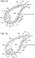
- impingement insert 180 in operation, impingement insert 180 can be forced into a compressed position by application of force F1, as shown in FIGS. 11 and 15 .
- force F1 As shown in FIGS. 11 and 15 .
- side walls 200, 202 of hollow body 190 are moved closer together.
- Cover 250 may also flex and be compressed, as shown in FIG. 11 .
- hollow body 190 is insertable in hollow cavity 172 of HGP component 122.
- Impingement insert 180 may extend the entire longitudinal extent of hollow cavity 172, which allows the entire impingement insert 180 to be inserted in one step and avoids having to position a number of impingement insert sections.
- Impingement insert 180 also avoids having to couple a number of impingement insert sections, as may be required in conventional settings.
- force F1 FIGS. 11 and 15
- force F1 FIGS. 11 and 15
- spring element 210 to move impingement insert 180 to the expanded position, shown in FIGS. 12 and 16 .
- hollow body 190 of impingement insert 180 expands to engage interior surface 184 of hollow cavity 172 of HGP component 122.
- Supports 224 FIGS. 6 and 8
- impingement insert 180 can be coupled to HGP component 122, e.g., by welding (e.g., spot welding) impingement insert 180 and/or cover 250 (when provided) to HGP component 122.
- Impingement inserts 180, closure 230 and/or cover 250 may be made by any now known or later developed process, e.g., stamping and welding, additive manufacture, etc.
- Embodiments of the disclosure provide an impingement insert and HGP component including an impingement insert that provides improved cooling performance by positioning the insert closer to the interior surface of the HGP component, e.g., airfoil inner wall.
- the insert can be easily inserted but end up closer to the targeted interior surface, allowing greater cooling effectiveness with less coolant flow and with a better Z/D parameter value.
Landscapes
- Engineering & Computer Science (AREA)
- Mechanical Engineering (AREA)
- General Engineering & Computer Science (AREA)
- Chemical & Material Sciences (AREA)
- Combustion & Propulsion (AREA)
- Physics & Mathematics (AREA)
- Fluid Mechanics (AREA)
- Turbine Rotor Nozzle Sealing (AREA)
Description
- The invention relates generally to turbomachinery, and more particularly, to an impingement insert for a hot gas path (HGP) component according to the preamble of independent claim 1. The invention also relates to a hot gas path (HGP) component.
- An impingement insert or sleeve includes a hollow body having cooling passages in a wall thereof that allow delivery of a coolant through the cooling passages to impact or impinge on a surface to be cooled. Impingement inserts are used in a variety of HGP components in turbomachinery to increase cooling performance of cooling circuitry therein. One indicator of cooling performance of an insert is the Z/D parameter, which is a ratio of a distance D between the insert and interior surface of the HGP component and a diameter D of the cooling passages (holes) in the impingement insert. The Z/D parameter value of an insert is typically designed to be within a desired range that results in better cooling performance. One challenge with impingement inserts is positioning the impingement insert within a cavity in an already formed HGP component, but also positioning the insert in a sufficiently close manner to allow for high cooling performance, i.e., observed by a lower Z/D parameter. One approach includes providing the impingement insert in a number of flexible, longitudinal sections to make it easier to insert them into the HGP component. However, having to sequentially position and couple a number of insert sections together or couple them to the HGP component, increases the complexity, time and costs of manufacture. Flexible impingement insert sections also do not provide a contiguous element about their periphery, i.e., laterally (cross-section), which can detract from cooling performance where they are discontinuous.
-
US3 806 275 A discloses an impingement insert formed as a blade liner mounted in a hollow cavity of a turbine blade, the impingement insert having the features of the preamble of independent claim 1. The blade liner is open a platform end and closed at the tip of the blade. -
US 5 516 260 A discloses an airfoil of a turbine blade including a radially extending cavity defined by an inner surface which has a plurality ribs and an impingement insert disposed on the inner surface. The insert includes a hollow body having a longitudinal extent, a first side wall, a second side wall contiguous with the first side wall at a first end of each, the second side wall configured to be flexibly movable relative to the first side wall, a plurality of cooling passages in the first and second side walls, the plurality of cooling passages passing between the exterior surface and the interior surface of the hollow body, and a spring element formed by a U-shaped fold in the insert and extending along its longitudinal extent of the hollow body and into the hollow body to be between the first side wall and the second side wall. The spring element biases the first side wall and the second side wall to an expanded position of the hollow body in abutting sealing contact with the ribs in the cavity from a compressed position of the hollow body. - A first aspect of the disclosure provides an impingement insert for a hot gas path (HGP) component, the impingement insert comprising: a hollow body having a longitudinal extent, an exterior surface and an interior surface, the hollow body further including: a first side wall, a second side wall contiguous with the first side wall at a first end of each, the second side wall configured to be flexibly movable relative to the first side wall, a closure on a first end of the hollow body, and a spring element contiguous with a second end of each of the first side wall and the second side wall, the spring element extending along at least a portion of the longitudinal extent of the hollow body and into the hollow body to be between the first side wall and the second side wall, the spring element biasing the first side wall and the second side wall to an expanded position of the hollow body from a compressed position of the hollow body; and a plurality of cooling passages in at least the first side wall and the second side wall, the plurality of cooling passages passing between the exterior surface and the interior surface of the hollow body. The closure includes a solid portion for closing a first portion of the first end of the hollow body and leaving a second portion of the first end of the hollow body open, wherein an end of the spring element adjacent the first end of the hollow body is free to move within the second portion of the first end of the hollow body not closed by the closure.
- A second aspect of the disclosure provides a hot gas path (HGP) component, comprising a component body having a hollow cavity therein, and an impingement insert as described before, the impingement insert mounted in the hollow cavity of the component body.
- The illustrative aspects of the present disclosure are designed to solve the problems herein described and/or other problems not discussed.
- These and other features of this disclosure will be more readily understood from the following detailed description of the various aspects of the disclosure taken in conjunction with the accompanying drawings that depict various embodiments of the disclosure, in which:
-
FIG. 1 shows a schematic view of an illustrative gas turbine system. -
FIG. 2 shows a cross-sectional view of an illustrative gas turbine assembly with a three stage nozzle that may be used with the GT system inFIG. 1 . -
FIG. 3 shows a perspective view of a turbine rotor blade of the type in which embodiments of the present disclosure may be employed. -
FIG. 4 shows a perspective view of a turbine nozzle or vane of the type in which embodiments of the present disclosure may be employed. -
FIG. 5 shows a top down view of an HGP component including an impingement sleeve with a spring element, according to one embodiment of the disclosure. -
FIG. 6 shows a perspective view of an impingement insert with a spring element, according to embodiments of the disclosure. -
FIG. 7 shows a top down view of the impingement insert ofFIG. 6 . -
FIG. 8 shows a side view of the impingement insert ofFIG. 6 . -
FIG. 9 shows an enlarged top down, partial cross-sectional view of a spring element according to another embodiment of the disclosure. -
FIG. 10 shows an enlarged top down, partial cross-sectional view of a spring element according to another embodiment of the disclosure. -
FIG. 11 shows an enlarged, side, partial cross-sectional view of a closure for an impingement insert in a compressed position, according to an embodiment of the disclosure. -
FIG. 12 shows an enlarged, side, partial cross-sectional view of the closure for the impingement insert fromFIG. 11 in an expanded position, according to an embodiment of the disclosure. -
FIG. 13 shows a top down view of a cover for an impingement insert, according to an embodiment of the disclosure. -
FIG. 14 shows a top down view of a cover for an impingement insert, according to another embodiment of the disclosure. -
FIG. 15 shows a top down view of an impingement insert in a compressed position for insertion into an HGP component, according to an embodiment of the disclosure. -
FIG. 16 shows a top down view of the impingement insert fromFIG. 15 in an expanded (and mounted) position in an HGP component, and an HGP component, according to an embodiment of the disclosure. - It is noted that the drawings of the disclosure are not necessarily to scale. The drawings are intended to depict only typical aspects of the disclosure, and therefore should not be considered as limiting the scope of the disclosure. In the drawings, like numbering represents like elements between the drawings.
- As an initial matter, in order to clearly describe the current disclosure it will become necessary to select certain terminology when referring to and describing relevant machine components within, for example, a turbomachine. When doing this, if possible, common industry terminology will be used and employed in a manner consistent with its accepted meaning. Unless otherwise stated, such terminology should be given a broad interpretation consistent with the context of the present application and the scope of the appended claims. Those of ordinary skill in the art will appreciate that often a particular component may be referred to using several different or overlapping terms. What may be described herein as being a single part may include and be referenced in another context as consisting of multiple components. Alternatively, what may be described herein as including multiple components may be referred to elsewhere as a single part.
- In addition, several descriptive terms may be used regularly herein, and it should prove helpful to define these terms at the onset of this section. These terms and their definitions, unless stated otherwise, are as follows. As used herein, "downstream" and "upstream" are terms that indicate a direction relative to the flow of a fluid, such as the working fluid through the turbine GT system or, for example, the flow of air through the combustor or coolant through one of the turbine's component systems. The term "downstream" corresponds to the direction of flow of the fluid, and the term "upstream" refers to the direction opposite to the flow. The terms "forward" and "aft," without any further specificity, refer to directions, with "forward" referring to the front or compressor end of the GT system, and "aft" referring to the rearward or turbine end of the GT system. It is often required to describe parts that are at differing radial positions with regard to a center axis. The term "radial" refers to movement or position perpendicular to an axis. In cases such as this, if a first component resides closer to the axis than a second component, it will be stated herein that the first component is "radially inward" or "inboard" of the second component. If, on the other hand, the first component resides further from the axis than the second component, it may be stated herein that the first component is "radially outward" or "outboard" of the second component. The term "axial" refers to movement or position parallel to an axis. Finally, the term "circumferential" refers to movement or position around an axis. It will be appreciated that such terms may be applied in relation to the center axis of the turbine.
- In addition, several descriptive terms may be used regularly herein, as described below. The terms "first", "second", and "third" may be used interchangeably to distinguish one component from another and are not intended to signify location or importance of the individual components.
- The terminology used herein is for the purpose of describing particular embodiments only and is not intended to be limiting of the disclosure. As used herein, the singular forms "a", "an" and "the" are intended to include the plural forms as well, unless the context clearly indicates otherwise. It will be further understood that the terms "comprises" and/or "comprising," when used in this specification, specify the presence of stated features, integers, steps, operations, elements, and/or components, but do not preclude the presence or addition of one or more other features, integers, steps, operations, elements, components, and/or groups thereof. "Optional" or "optionally" means that the subsequently described event or circumstance may or may not occur, and that the description includes instances where the event occurs and instances where it does not.
- Where an element or layer is referred to as being "on," "engaged to," "disengaged from," "connected to" or "coupled to" another element or layer, it may be directly on, engaged, connected or coupled to the other element or layer, or intervening elements or layers may be present. In contrast, when an element is referred to as being "directly on," "directly engaged to," "directly connected to" or "directly coupled to" another element or layer, there may be no intervening elements or layers present. Other words used to describe the relationship between elements should be interpreted in a like fashion (e.g., "between" versus "directly between," "adjacent" versus "directly adjacent," etc.). As used herein, the term "and/or" includes any and all combinations of one or more of the associated listed items.
- As indicated above, the disclosure provides an impingement insert for an HGP component and an HGP component that includes the impingement insert. The impingement insert, which may also be referred to as an impingement sleeve, includes a hollow body having a longitudinal extent, an exterior surface and an interior surface. The hollow body includes a first side wall and a second side wall contiguous with the first side wall at a first end of each. The second side wall is flexibly movable relative to the first side wall. A spring element is contiguous with a second end of each of the first side wall and the second side wall, and extends along at least a portion of the longitudinal extent of the hollow body. The spring element also extends into the hollow body between the first side wall and the second side wall. The spring element biases the side walls to an expanded position from a compressed position of the hollow body. Cooling passages pass between the exterior surface and the interior surface of the hollow body in both side walls. The impingement insert is compressible and/or flexible laterally such that it can be compressed, inserted into a hollow cavity in an already formed HGP component, released to fill the shape of the hollow cavity and fixed into position. The impingement insert extends an entire length of the hollow cavity in the HGP component, i.e., it is not sectioned, making its insertion a one-step operation. Further, the impingement insert is contiguous laterally, i.e., in a circumferential cross-section, so as to avoid creating areas of poor cooling performance.
-
FIG. 1 shows a schematic illustration of an illustrative machine in the form of aturbomachine 90 that includes a hot gas path (HGP) component including an impingement insert according to embodiments of the disclosure. In the example shown,turbomachine 90 includes a gas turbine (GT)system 100 that includes acompressor 102 and acombustor 104.Combustor 104 includes acombustion region 105 and afuel nozzle assembly 106.GT system 100 also includes aturbine 108 and a common compressor/turbine shaft 110 (sometimes referred to as rotor 110). In one embodiment,GT system 100 is a MS7001FB GT system, sometimes referred to as a 9FB GT system, commercially available from General Electric Company, Greenville, S.C. The present disclosure is not limited to any one particular GT system and may be implanted in connection with other GT systems including, for example, the MS7001FA (7FA) and MS9001FA (9FA) GT system models of General Electric Company. - In operation, air flows through
compressor 102 and compressed air is supplied tocombustor 104. Specifically, the compressed air is supplied to fuelnozzle assembly 106 that is integral tocombustor 104.Assembly 106 is in flow communication withcombustion region 105.Fuel nozzle assembly 106 is also in flow communication with a fuel source (not shown inFIG. 1 ) and channels fuel and air tocombustion region 105.Combustor 104 ignites and combusts fuel.Combustor 104 is in flow communication withturbine 108 for which gas stream thermal energy is converted to mechanical rotational energy.Turbine 108 is rotatably coupled to and drivesrotor 110.Compressor 102 also is rotatably coupled toshaft 110. In the illustrative embodiment, there is a plurality ofcombustors 104 andfuel nozzle assemblies 106. -
FIG. 2 shows a cross-sectional illustration of anillustrative turbine 108 with a three stage nozzle that may be used withGT system 100 inFIG. 1 .Turbine 108 includes astationary vane 112.Stationary vane 112 is held in theturbine assembly 108 by a radially outer platform 114 and a radiallyinner platform 116.Stationary vane 112 may include one or more circumferentially spaced airfoils 156 (FIG. 4 ). Rotatingblades 120 are coupled torotor 110 and extend between rows ofstationary vanes 112. As will be further described, combustion gases are directed bystationary vanes 112 againstrotating blades 120 to turnrotor 110. -
FIGS. 3 and4 showillustrative HGP components 122 ofGT system 100 in which an impingement insert according to embodiments of the disclosure may be employed.FIG. 3 shows a perspective view of aturbine rotor blade 130 of the type in which embodiments of the present disclosure may be employed.Turbine rotor blade 130 includes aroot 132 by whichrotor blade 130 attaches to rotor 110 (FIGS. 1-2 ).Root 132 may include a dovetail configured for mounting in a corresponding dovetail slot in the perimeter of the rotor disc.Root 132 may further include a shank that extends between the dovetail and aplatform 134, which is disposed at the junction ofairfoil 136 androot 132 and defines a portion of the inboard boundary of the flow path throughturbine 108. It will be appreciated thatairfoil 136 is the active component ofrotor blade 130 that intercepts the flow of working fluid and induces the rotor disc to rotate. It will be seen thatairfoil 136 ofrotor blade 130 includes a concave pressure side (PS)outer wall 140 and a circumferentially or laterally opposite convex suction side (SS)outer wall 142 extending axially between opposite leading and trailingedges Outer walls platform 134 to anoutboard tip 148. -
FIG. 4 shows a perspective view of a stationary nozzle orvane 150 of the type in which embodiments of the present disclosure may be employed.Stationary vane 150 includes anouter platform 152 by whichstationary vane 150 attaches to a casing of the turbomachine.Outer platform 152 may include any now known or later developed mounting configuration for mounting in a corresponding mount in the casing.Stationary vane 150 may further include aninner platform 154 for positioning between adjacentturbine rotor blades 120, 130 (FIGS. 2 and3 ) platforms 134 (FIG. 3 ).Platforms GT system 100. It will be appreciated thatairfoil 156 is the active component ofstationary vane 150 that intercepts the flow of working fluid and directs it towards turbine rotor blades 130 (FIG. 3 ). It will be seen thatairfoil 156 ofstationary vane 150 includes a concave pressure side (PS)outer wall 160 and a circumferentially or laterally opposite convex suction side (SS)outer wall 162 extending axially between opposite leading and trailingedges Outer walls platform 154 toplatform 152. - As understood in the art, an impingement insert is employed in
HGP component 122 of, for example,GT system 100, to distribute a cooling fluid to the HGP component.HGP component 122 may include, for example,rotating blade 130 orstationary vane 150, and/orairfoils FIG. 5 shows a schematic view of anillustrative HGP component 122 including ahollow cavity 172 in acomponent body 170 thereof, e.g., in either ofairfoils 136, 156 (FIGS. 3 and4 ). That is,HGP component 122 includescomponent body 170 havinghollow cavity 172 therein into which animpingement insert 180 is positioned. Typically, a coolant like air or steam is supplied to an interior ofimpingement insert 180, and exits through cooling passages (not shown inFIG. 5 ) therein. The exiting coolant impinges on aninterior surface 184 ofHGP component 122 and cools the HGP component. Where HGP component includes anairfoil hollow cavity 172 therein that extends a substantial portion of a length thereof. Embodiments of animpingement insert 180 according to embodiments of the disclosure can be applied inhollow cavity 172 in, for example, airfoil(s) 136, 156 (FIGS. 3 and4 ). As will be described,hollow body 190 is contiguous in a chordwise direction of the airfoil, i.e., in a circumferential cross-section of the airfoil. While the teachings of the disclosure will be described relative toGT system 100, rotatingblades stationary vanes airfoils -
FIGS. 6-8 show various views of animpingement insert 180 according to embodiments of the disclosure.FIG. 6 shows a perspective view,FIG. 7 shows a top down view, andFIG. 8 shows a side view of animpingement insert 180 according to embodiments of the disclosure.Impingement insert 180 includes ahollow body 190 having a longitudinal extent L (FIG. 8 only),exterior surface 192 and aninterior surface 194. Longitudinal extent L may be any length necessary for operation of theparticular impingement insert 180, which depends on its function. Animpingement insert 180 may have a length L to match that ofhollow cavity 172 ofcomponent body 170, e.g., in a vane or blade. In this regard, use ofimpingement insert 180 allows a one-step operation of inserting the impingement insert into the HGP component.Hollow body 190 also includes afirst side wall 200 and asecond side wall 202.Second side wall 202 is contiguous withfirst side wall 200 at afirst end 204 of each. That is, first andsecond side wall first end 204. As illustrated, first andsecond side wall interior surface 184 ofhollow cavity 172 ofHGP component 122.Side walls first side wall 200 andsecond side wall 202 can bend relative to one another, e.g., towards one another, without breaking.Hollow body 190 also includes aspring element 210 contiguous with asecond end 212 of each offirst side wall 200 andsecond side wall 202. Second ends 212 of side walls are spaced from one another such thatspring element 200 may extend along at least a portion of the longitudinal extent L (FIG. 6 ) ofhollow body 190. In the example shown,spring element 210 extends an entire length ofhollow body 190, but this is not necessary in all cases.Spring element 210 also extends intohollow body 190 to be betweenfirst side wall 200 andsecond side wall 202. That is,spring element 210 extends betweenside walls hollow body 190.Spring element 210 extending intohollow body 190 betweenfirst side wall 200 andsecond side wall 202 provides a smaller, more compact, footprint for impingement insert and makes it easier to insert intoHGP component 122. - As shown in
FIGS. 6-8 ,impingement insert 180 also includes a plurality of coolingpassages 220 in at leastfirst side wall 200 andsecond side wall 202. Coolingpassages 220 pass betweenexterior surface 192 andinterior surface 194 ofhollow body 190. Coolingpassages 220 allow coolant to pass fromhollow body 190 to impinge interior surface 184 (FIG. 5 ) ofhollow cavity 172 incomponent body 170 ofHGP component 122. Any number, shape, size or arrangement of coolingpassages 220 may be provided. -
Spring element 210 biasesfirst side wall 200 andsecond side wall 202 to an expanded position ofhollow body 190, shown inFIGS. 5-8 ,12-14 and16 , from a compressed position ofhollow body 190, shown inFIGS. 11 and15 .Spring element 210 may include any now known or later developed spring capable of withstanding the environment ofHGP component 122, and providing sufficient force F2 (FIG. 12 ) to expand first andsecond side wall FIGS. 5-8 ,11-16 ,spring element 210 includes a V-spring 214 having apoint 216 thereof extending intohollow body 190 betweenfirst side wall 200 andsecond side wall 202. In other examples, shown in the enlarged top down, partial cross-sectional views ofFIGS. 9 and 10 ,spring element 210 may have a sinusoidal shape with any number of waves therein, e.g., with two (W-shaped inFIG. 9 ) or more peaks (FIG. 10 ). Other shapes forspring element 210 may also be possible. - As shown best in
FIGS. 6 and8 ,impingement insert 180 may also include a plurality ofsupports 224 onexterior surface 192 offirst side wall 200 andsecond side wall 202 ofhollow body 190.Supports 224 may positionhollow body 190 relative to interior surface 184 (FIG. 5 ) ofhollow cavity 172 ofHGP component 122, and may assist in heat transfer. Any number ofsupports 224 operable to positionimpingement insert 180 relative to interior surface 184 (FIG. 5 ), or provide the desired heat transfer, can be used.Supports 224 can have any desired shape configured to position the insert relative to interior surface 184 (FIG. 5 ) and/or provide the desired heat transfer, e.g., fins, pins and/or chevrons, etc. - As shown in
FIGS. 5 ,7 ,11-16 ,impingement insert 180 also includes aclosure 230 on a first end 232 (FIGS. 11-12 ) ofhollow body 190.FIG. 11 shows a cross-sectional view of an end ofhollow body 190 in a compressed position, andFIG. 12 shows a cross-sectional view of an end ofhollow body 190 in an expanded position. As shown best inFIGS. 5 and7 ,closure 230 includes asolid portion 234 for closing afirst portion 236 offirst end 232 ofhollow body 190 and leaving asecond portion 238 offirst end 232 ofhollow body 190 open.Closure 230 may be coupled tofirst end 232 in any now known or later developed manner, e.g., welding, additively manufactured together, etc.Closure 230 may be shaped to match a shape offirst portion 236 betweenfirst side wall 200 andsecond side wall 202, e.g., partially shaped like a circumferential cross-section of an airfoil.Closure 230 may have any shapededge 240 that defines opensecond portion 238 with remaining edges offirst side wall 200 andsecond side wall 202. In addition,edge 240 ofclosure 230 may be shaped and positioned to allow opensecond portion 238 to provide sufficient space forspring element 210 movement. In this regard, as shown inFIGS. 11 and 12 , anend 246 ofspring element 210 adjacentfirst end 232 ofhollow body 190 is free to move within (open)second portion 238 offirst end 232 ofhollow body 190 not closed byclosure 230, i.e., asspring element 210 moves between the expanded and compressed positions. InFIGS. 5 and7 ,edge 240 is linear, but for example, inFIG. 13 ,edge 240 is V-shaped, and inFIG. 14 ,edge 240 is curved.FIGS. 11 and 12 illustrate thatsolid portion 234 ofclosure 230 may be configured to flex withfirst side wall 200 andsecond side wall 202 ofhollow body 190 as the side walls move between an expanded position, shown inFIG. 12 , ofhollow body 190 and, as shown inFIG. 11 , a compressed position ofhollow body 190. As illustrated,solid portion 234 may bow outwardly fromhollow body 190 to accommodate the compression, but this may not be necessary in all instances.Solid portion 234 may be configured to flex in any now known or later developed manner, e.g., made of flexible metal, formed slightly curved, slotted or otherwise structured to accommodate flexing.Solid portion 234 could also be configured to bow inwardly intohollow body 190. In an expanded position, shown inFIG. 12 ,solid portion 234 may be substantially planar. -
Impingement insert 180 may also optionally include any now known or later developedcover 250.Impingement insert 180 can also be devoid of a cover. Acover 250 may be provided for connection tointerior surface 184 ofhollow cavity 172, near an end of the hollow cavity, to seal or reduce flow out of an end of the space between exterior surface 192 (FIG. 8 ) ofhollow body 190 and interior surface 184 (FIG. 5 ) ofhollow cavity 172 ofHGP component 122. Cover 250 may also act to space impingement insert frominterior surface 184 ofhollow cavity 172. As shown for example inFIGS. 6 and8 , cover 250 may extend laterally outward on asecond end 252 ofhollow body 190 opposing first end 232 (FIG. 6 ) ofhollow body 190. Cover 250 is configured to be coupled toHGP component 122, e.g., it has an inner shape to matchhollow body 190 at the end thereof. Cover 250 can be coupled tohollow body 190, for example, by welding. Cover 250 may be a flexible member that includes agap 254 defined therein at a location ofspring element 210 to provide some flexibility. That is,cover 250 may not be continuous wherespring element 210 exists, e.g., to allowspring element 210 to move, and cover 250 to flex ashollow body 190 is compressed.Gap 254 may have any size capable of providing the desired flexibility. In another embodiment, shown inFIG. 13 ,impingement insert 180 may include atriangular cover 258 fixed overspring element 210, e.g., welded together once the insert is in position inHGP component 122. In another embodiment, shown inFIG. 14 ,cover 250 may include a plurality of spacedslots 256 therein that allow it to flex, but can be welded into a fixed location onceimpingement insert 180 is in position inHGP component 122. - Referring to
FIGS. 11, 12 ,15 and 16 , in operation,impingement insert 180 can be forced into a compressed position by application of force F1, as shown inFIGS. 11 and15 . In the compressed position,side walls hollow body 190 are moved closer together. Cover 250 may also flex and be compressed, as shown inFIG. 11 . As shown inFIG. 15 , in the compressed position,hollow body 190 is insertable inhollow cavity 172 ofHGP component 122.Impingement insert 180 may extend the entire longitudinal extent ofhollow cavity 172, which allows theentire impingement insert 180 to be inserted in one step and avoids having to position a number of impingement insert sections.Impingement insert 180 also avoids having to couple a number of impingement insert sections, as may be required in conventional settings. Once inserted inhollow cavity 172 ofHGP component 122, force F1 (FIGS. 11 and15 ) can be removed, allowingspring element 210 to moveimpingement insert 180 to the expanded position, shown inFIGS. 12 and16 . In the expanded position shown inFIG. 16 ,hollow body 190 ofimpingement insert 180 expands to engageinterior surface 184 ofhollow cavity 172 ofHGP component 122. Supports 224 (FIGS. 6 and8 )position impingement insert 180 at the desired distance away frominterior surface 184. Once in position,impingement insert 180 can be coupled toHGP component 122, e.g., by welding (e.g., spot welding)impingement insert 180 and/or cover 250 (when provided) toHGP component 122. - Impingement inserts 180,
closure 230 and/or cover 250 may be made by any now known or later developed process, e.g., stamping and welding, additive manufacture, etc. - Embodiments of the disclosure provide an impingement insert and HGP component including an impingement insert that provides improved cooling performance by positioning the insert closer to the interior surface of the HGP component, e.g., airfoil inner wall. By having a flexible insert that can expand, the insert can be easily inserted but end up closer to the targeted interior surface, allowing greater cooling effectiveness with less coolant flow and with a better Z/D parameter value.
Claims (11)
- An impingement insert (180) for a hot gas path (HGP) component(122), the impingement insert (180) comprising:
a hollow body (190) having a longitudinal extent, an exterior surface (192) and an interior surface (184, 194), the hollow body (190) further including:a first side wall (200),a second side wall (202) contiguous with the first side wall (200) at a first end (204, 232) of each, the second side wall (202) configured to be flexibly movable relative to the first side wall (200),a closure (230) on a first end (204, 232) of the hollow body (190);a spring element (210) contiguous with a second end (212, 252) of each of the first side wall (200) and the second side wall (202), the spring element (210) extending along at least a portion of the longitudinal extent of the hollow body (190) and into the hollow body (190) to be between the first side wall (200) and the second side wall (202), the spring element (210) biasing the first side wall (200) and the second side wall (202) to an expanded position of the hollow body (190) from a compressed position of the hollow body (190); anda plurality of cooling passages (220) in at least the first side wall (200) and the second side wall (202), the plurality of cooling passages (220) passing between the exterior surface (192) and the interior surface (184, 194) of the hollow body (190);characterized bythe closure (230) including a solid portion (234) for closing a first portion (236) of the first end (204, 232) of the hollow body (190) and leaving a second portion (238) of the first end (204, 232) of the hollow body (190) open;wherein an end (246) of the spring element (210) adjacent the first end (204, 232) of the hollow body (190) is free to move within the second portion (238) of the first end (204, 232) of the hollow body (190) not closed by the closure (230). - The impingement insert (180) of claim 1, further comprising a plurality of supports (224) on the exterior surface (192) of the first side wall (200) and the second side wall (202) of the hollow body (190) to position the hollow body (190) relative to an interior surface (184, 194) of a hollow cavity (172) of the HGP component (122).
- The impingement insert (180) of claim 2, wherein in the compressed position, the hollow body (190) is insertable in the hollow cavity (172) of the HGP component (122), and in the expanded position, the hollow body (190) expands to engage the interior surface (184, 194) of the hollow cavity (172) of the HGP component (122).
- The impingement insert (180) of claim 1, wherein the solid portion (234) of the closure (230) is configured to flex with the first side wall (200) and the second side wall (202) of the hollow body (190) as the first side wall (200) and the second side wall (202) move between the expanded position of the hollow body (190) and the compressed position of the hollow body (190).
- The impingement insert (180) of claim 1, further comprising a cover (250) extending laterally outward on a second end (212, 252) of the hollow body (190) opposing the first end (204, 232) of the hollow body (190), the cover (250) configured to be coupled to the HGP component (122).
- The impingement insert (180) of claim 5, wherein the cover (250) includes a plurality of spaced slots (256) therein.
- The impingement insert (180) of claim 5, wherein the cover (250) includes a gap (254) defined therein at a location of the spring element (210).
- The impingement insert (180) of claim 5, wherein the cover (250) further includes a triangular cover (258) mounted over the spring element (210).
- The impingement insert (180) of claim 1, wherein the spring element (210) includes a V-spring (214) having a point (216) thereof extending into the hollow body (190) between the first side wall (200) and the second side wall (202).
- The impingement insert (180) of claim 1, wherein the HGP component (122) includes an airfoil (136) having a hollow cavity (172) therein, and wherein the hollow body (190) is contiguous in a chordwise direction of the airfoil (136).
- A hot gas path (HGP) component (122), comprising:a component body (170) having a hollow cavity (172) therein; andan impingement insert (180) according to anyone of the preceding claims, the impingement insert (180) mounted in the hollow cavity (172).
Applications Claiming Priority (1)
| Application Number | Priority Date | Filing Date | Title |
|---|---|---|---|
| US16/701,408 US11085374B2 (en) | 2019-12-03 | 2019-12-03 | Impingement insert with spring element for hot gas path component |
Publications (2)
| Publication Number | Publication Date |
|---|---|
| EP3832070A1 EP3832070A1 (en) | 2021-06-09 |
| EP3832070B1 true EP3832070B1 (en) | 2023-08-02 |
Family
ID=73497703
Family Applications (1)
| Application Number | Title | Priority Date | Filing Date |
|---|---|---|---|
| EP20208776.3A Active EP3832070B1 (en) | 2019-12-03 | 2020-11-19 | Impingement insert for a hot gas path component and hot gas path component |
Country Status (4)
| Country | Link |
|---|---|
| US (1) | US11085374B2 (en) |
| EP (1) | EP3832070B1 (en) |
| JP (1) | JP7608123B2 (en) |
| CN (1) | CN112901281B (en) |
Families Citing this family (1)
| Publication number | Priority date | Publication date | Assignee | Title |
|---|---|---|---|---|
| US11603766B1 (en) * | 2022-05-04 | 2023-03-14 | Pratt & Whitney Canada Corp. | Turbine stator vanes having inserts and splitter plates |
Family Cites Families (42)
| Publication number | Priority date | Publication date | Assignee | Title |
|---|---|---|---|---|
| US3540810A (en) * | 1966-03-17 | 1970-11-17 | Gen Electric | Slanted partition for hollow airfoil vane insert |
| US3806275A (en) | 1972-08-30 | 1974-04-23 | Gen Motors Corp | Cooled airfoil |
| GB1587401A (en) * | 1973-11-15 | 1981-04-01 | Rolls Royce | Hollow cooled vane for a gas turbine engine |
| US4153386A (en) * | 1974-12-11 | 1979-05-08 | United Technologies Corporation | Air cooled turbine vanes |
| US4063851A (en) * | 1975-12-22 | 1977-12-20 | United Technologies Corporation | Coolable turbine airfoil |
| US4257734A (en) * | 1978-03-22 | 1981-03-24 | Rolls-Royce Limited | Guide vanes for gas turbine engines |
| GB2051964B (en) | 1979-06-30 | 1983-01-12 | Rolls Royce | Turbine blade |
| FR2473621A1 (en) * | 1980-01-10 | 1981-07-17 | Snecma | DAWN OF TURBINE DISPENSER |
| US4482295A (en) * | 1982-04-08 | 1984-11-13 | Westinghouse Electric Corp. | Turbine airfoil vane structure |
| GB2119028B (en) * | 1982-04-27 | 1985-02-27 | Rolls Royce | Aerofoil for a gas turbine engine |
| US5516260A (en) * | 1994-10-07 | 1996-05-14 | General Electric Company | Bonded turbine airfuel with floating wall cooling insert |
| JPH09303106A (en) * | 1996-05-16 | 1997-11-25 | Mitsubishi Heavy Ind Ltd | Gas turbine cooling blade |
| GB2350867B (en) * | 1999-06-09 | 2003-03-19 | Rolls Royce Plc | Gas turbine airfoil internal air system |
| GB0001679D0 (en) | 2000-01-26 | 2000-03-15 | Rolls Royce Plc | Method of producing a lining artefact |
| JP3782637B2 (en) | 2000-03-08 | 2006-06-07 | 三菱重工業株式会社 | Gas turbine cooling vane |
| US6428270B1 (en) | 2000-09-15 | 2002-08-06 | General Electric Company | Stage 3 bucket shank bypass holes and related method |
| US6428273B1 (en) * | 2001-01-05 | 2002-08-06 | General Electric Company | Truncated rib turbine nozzle |
| JP2005069236A (en) | 2004-12-10 | 2005-03-17 | Toshiba Corp | Turbine cooling blade |
| US20090165924A1 (en) * | 2006-11-28 | 2009-07-02 | General Electric Company | Method of manufacturing cmc articles having small complex features |
| US8257035B2 (en) | 2007-12-05 | 2012-09-04 | Siemens Energy, Inc. | Turbine vane for a gas turbine engine |
| JP2009162119A (en) * | 2008-01-08 | 2009-07-23 | Ihi Corp | Turbine blade cooling structure |
| GB201103317D0 (en) * | 2011-02-28 | 2011-04-13 | Rolls Royce Plc | |
| EP2573325A1 (en) | 2011-09-23 | 2013-03-27 | Siemens Aktiengesellschaft | Impingement cooling of turbine blades or vanes |
| CA2870740C (en) | 2012-04-23 | 2017-06-13 | General Electric Company | Turbine airfoil with local wall thickness control |
| US9470095B2 (en) | 2012-04-24 | 2016-10-18 | United Technologies Corporation | Airfoil having internal lattice network |
| US20140093392A1 (en) * | 2012-10-03 | 2014-04-03 | Rolls-Royce Plc | Gas turbine engine component |
| EP3039248B1 (en) * | 2013-08-30 | 2021-08-04 | Raytheon Technologies Corporation | Gas turbine engine vane |
| EP2990607A1 (en) * | 2014-08-28 | 2016-03-02 | Siemens Aktiengesellschaft | Cooling concept for turbine blades or vanes |
| US20160146019A1 (en) | 2014-11-26 | 2016-05-26 | Elena P. Pizano | Cooling channel for airfoil with tapered pocket |
| US10053996B2 (en) * | 2014-12-12 | 2018-08-21 | United Technologies Corporation | Sliding baffle inserts |
| CN108026773B (en) * | 2015-08-28 | 2020-02-21 | 西门子公司 | Turbine airfoil with partially sealed radial passages with flow displacement features |
| EP3325774B1 (en) * | 2015-08-28 | 2019-06-19 | Siemens Aktiengesellschaft | Turbine airfoil with internal impingement cooling feature |
| US10113441B2 (en) * | 2016-01-07 | 2018-10-30 | United Technologies Corporation | Thermally driven spring valve for turbine gas path parts |
| US10519779B2 (en) | 2016-03-16 | 2019-12-31 | General Electric Company | Radial CMC wall thickness variation for stress response |
| WO2017171764A1 (en) * | 2016-03-31 | 2017-10-05 | Siemens Aktiengesellschaft | Turbine airfoil with internal cooling channels having flow splitter feature |
| US10436037B2 (en) | 2016-07-22 | 2019-10-08 | General Electric Company | Blade with parallel corrugated surfaces on inner and outer surfaces |
| GB2555632A (en) | 2016-11-07 | 2018-05-09 | Rolls Royce Plc | Self-sealing impingement cooling tube for a turbine vane |
| US10408090B2 (en) * | 2016-11-17 | 2019-09-10 | United Technologies Corporation | Gas turbine engine article with panel retained by preloaded compliant member |
| US10260363B2 (en) * | 2016-12-08 | 2019-04-16 | General Electric Company | Additive manufactured seal for insert compartmentalization |
| US20180328187A1 (en) * | 2017-05-09 | 2018-11-15 | General Electric Company | Turbine engine with an airfoil and insert |
| US10544682B2 (en) * | 2017-08-14 | 2020-01-28 | United Technologies Corporation | Expansion seals for airfoils |
| US10934857B2 (en) * | 2018-12-05 | 2021-03-02 | Raytheon Technologies Corporation | Shell and spar airfoil |
-
2019
- 2019-12-03 US US16/701,408 patent/US11085374B2/en active Active
-
2020
- 2020-11-04 CN CN202011218002.XA patent/CN112901281B/en active Active
- 2020-11-16 JP JP2020190540A patent/JP7608123B2/en active Active
- 2020-11-19 EP EP20208776.3A patent/EP3832070B1/en active Active
Also Published As
| Publication number | Publication date |
|---|---|
| US11085374B2 (en) | 2021-08-10 |
| JP7608123B2 (en) | 2025-01-06 |
| JP2021088987A (en) | 2021-06-10 |
| CN112901281A (en) | 2021-06-04 |
| CN112901281B (en) | 2025-08-05 |
| EP3832070A1 (en) | 2021-06-09 |
| US20210164397A1 (en) | 2021-06-03 |
Similar Documents
| Publication | Publication Date | Title |
|---|---|---|
| EP3022394B1 (en) | Turbine nozzle with impingement baffle | |
| EP3060830B1 (en) | Annular cartridge seal | |
| CN107035422B (en) | Turbine rotor blade with midspan shroud | |
| EP3155230B1 (en) | Multi-piece shroud hanger assembly | |
| EP4283094B1 (en) | Turbine component with stress relieving cooling circuit | |
| EP1657405B1 (en) | Stator vane assembly for a gas turbine | |
| KR20200010091A (en) | Turbine shroud including plurality of cooling passages | |
| JPH07180504A (en) | gas turbine | |
| US10066488B2 (en) | Turbomachine blade with generally radial cooling conduit to wheel space | |
| EP3645839B1 (en) | Turbine assembly for impingement cooling and method of assembling | |
| CN104420891A (en) | Blade of a rotary flow machine with a radial strip seal | |
| US11846193B2 (en) | Turbine engine assembly | |
| EP3415719B1 (en) | Turbomachine blade cooling structure | |
| EP2221453B1 (en) | Airfoil insert and corresponding airfoil and assembly | |
| US10914182B2 (en) | Gas turbine | |
| CN113250766B (en) | Hot gas path components including the rear exhaust pipe and rear flange | |
| US11085374B2 (en) | Impingement insert with spring element for hot gas path component | |
| JP7451512B2 (en) | Airfoil coupon installation | |
| EP4317649B1 (en) | Turbine airfoil with leading edge cooling passages coupled via a plenum to film cooling holes | |
| US11225872B2 (en) | Turbine blade with tip shroud cooling passage | |
| JP7825947B2 (en) | Cast turbine nozzle with heat transfer projections on the inner surface of the leading edge | |
| EP3015657A1 (en) | Gas turbine nozzle vane segment | |
| CN110249112B (en) | Turbine engine component with insert | |
| US20250012191A1 (en) | Turbine blade under-platform structure and pocket | |
| EP4321732B1 (en) | Turbine nozzle with planar surface adjacent side slash face |
Legal Events
| Date | Code | Title | Description |
|---|---|---|---|
| PUAI | Public reference made under article 153(3) epc to a published international application that has entered the european phase |
Free format text: ORIGINAL CODE: 0009012 |
|
| STAA | Information on the status of an ep patent application or granted ep patent |
Free format text: STATUS: THE APPLICATION HAS BEEN PUBLISHED |
|
| AK | Designated contracting states |
Kind code of ref document: A1 Designated state(s): AL AT BE BG CH CY CZ DE DK EE ES FI FR GB GR HR HU IE IS IT LI LT LU LV MC MK MT NL NO PL PT RO RS SE SI SK SM TR |
|
| STAA | Information on the status of an ep patent application or granted ep patent |
Free format text: STATUS: REQUEST FOR EXAMINATION WAS MADE |
|
| 17P | Request for examination filed |
Effective date: 20211129 |
|
| RBV | Designated contracting states (corrected) |
Designated state(s): AL AT BE BG CH CY CZ DE DK EE ES FI FR GB GR HR HU IE IS IT LI LT LU LV MC MK MT NL NO PL PT RO RS SE SI SK SM TR |
|
| RIC1 | Information provided on ipc code assigned before grant |
Ipc: B22F 5/04 20060101ALN20230201BHEP Ipc: B22F 5/00 20060101ALN20230201BHEP Ipc: F01D 9/06 20060101ALI20230201BHEP Ipc: F01D 5/18 20060101AFI20230201BHEP |
|
| GRAP | Despatch of communication of intention to grant a patent |
Free format text: ORIGINAL CODE: EPIDOSNIGR1 |
|
| STAA | Information on the status of an ep patent application or granted ep patent |
Free format text: STATUS: GRANT OF PATENT IS INTENDED |
|
| GRAJ | Information related to disapproval of communication of intention to grant by the applicant or resumption of examination proceedings by the epo deleted |
Free format text: ORIGINAL CODE: EPIDOSDIGR1 |
|
| STAA | Information on the status of an ep patent application or granted ep patent |
Free format text: STATUS: REQUEST FOR EXAMINATION WAS MADE |
|
| INTG | Intention to grant announced |
Effective date: 20230310 |
|
| INTC | Intention to grant announced (deleted) | ||
| RIC1 | Information provided on ipc code assigned before grant |
Ipc: B22F 5/04 20060101ALN20230328BHEP Ipc: B22F 5/00 20060101ALN20230328BHEP Ipc: F01D 9/06 20060101ALI20230328BHEP Ipc: F01D 5/18 20060101AFI20230328BHEP |
|
| GRAP | Despatch of communication of intention to grant a patent |
Free format text: ORIGINAL CODE: EPIDOSNIGR1 |
|
| STAA | Information on the status of an ep patent application or granted ep patent |
Free format text: STATUS: GRANT OF PATENT IS INTENDED |
|
| INTG | Intention to grant announced |
Effective date: 20230509 |
|
| GRAS | Grant fee paid |
Free format text: ORIGINAL CODE: EPIDOSNIGR3 |
|
| GRAA | (expected) grant |
Free format text: ORIGINAL CODE: 0009210 |
|
| STAA | Information on the status of an ep patent application or granted ep patent |
Free format text: STATUS: THE PATENT HAS BEEN GRANTED |
|
| AK | Designated contracting states |
Kind code of ref document: B1 Designated state(s): AL AT BE BG CH CY CZ DE DK EE ES FI FR GB GR HR HU IE IS IT LI LT LU LV MC MK MT NL NO PL PT RO RS SE SI SK SM TR |
|
| REG | Reference to a national code |
Ref country code: GB Ref legal event code: FG4D |
|
| REG | Reference to a national code |
Ref country code: CH Ref legal event code: EP |
|
| REG | Reference to a national code |
Ref country code: DE Ref legal event code: R096 Ref document number: 602020014861 Country of ref document: DE |
|
| REG | Reference to a national code |
Ref country code: IE Ref legal event code: FG4D |
|
| REG | Reference to a national code |
Ref country code: DE Ref legal event code: R081 Ref document number: 602020014861 Country of ref document: DE Owner name: GENERAL ELECTRIC TECHNOLOGY GMBH, CH Free format text: FORMER OWNER: GENERAL ELECTRIC COMPANY, SCHENECTADY, NY, US |
|
| REG | Reference to a national code |
Ref country code: LT Ref legal event code: MG9D |
|
| REG | Reference to a national code |
Ref country code: NL Ref legal event code: MP Effective date: 20230802 |
|
| RAP2 | Party data changed (patent owner data changed or rights of a patent transferred) |
Owner name: GENERAL ELECTRIC TECHNOLOGY GMBH |
|
| REG | Reference to a national code |
Ref country code: AT Ref legal event code: MK05 Ref document number: 1594982 Country of ref document: AT Kind code of ref document: T Effective date: 20230802 |
|
| PG25 | Lapsed in a contracting state [announced via postgrant information from national office to epo] |
Ref country code: GR Free format text: LAPSE BECAUSE OF FAILURE TO SUBMIT A TRANSLATION OF THE DESCRIPTION OR TO PAY THE FEE WITHIN THE PRESCRIBED TIME-LIMIT Effective date: 20231103 |
|
| PG25 | Lapsed in a contracting state [announced via postgrant information from national office to epo] |
Ref country code: IS Free format text: LAPSE BECAUSE OF FAILURE TO SUBMIT A TRANSLATION OF THE DESCRIPTION OR TO PAY THE FEE WITHIN THE PRESCRIBED TIME-LIMIT Effective date: 20231202 |
|
| PG25 | Lapsed in a contracting state [announced via postgrant information from national office to epo] |
Ref country code: SE Free format text: LAPSE BECAUSE OF FAILURE TO SUBMIT A TRANSLATION OF THE DESCRIPTION OR TO PAY THE FEE WITHIN THE PRESCRIBED TIME-LIMIT Effective date: 20230802 Ref country code: RS Free format text: LAPSE BECAUSE OF FAILURE TO SUBMIT A TRANSLATION OF THE DESCRIPTION OR TO PAY THE FEE WITHIN THE PRESCRIBED TIME-LIMIT Effective date: 20230802 Ref country code: PT Free format text: LAPSE BECAUSE OF FAILURE TO SUBMIT A TRANSLATION OF THE DESCRIPTION OR TO PAY THE FEE WITHIN THE PRESCRIBED TIME-LIMIT Effective date: 20231204 Ref country code: NO Free format text: LAPSE BECAUSE OF FAILURE TO SUBMIT A TRANSLATION OF THE DESCRIPTION OR TO PAY THE FEE WITHIN THE PRESCRIBED TIME-LIMIT Effective date: 20231102 Ref country code: NL Free format text: LAPSE BECAUSE OF FAILURE TO SUBMIT A TRANSLATION OF THE DESCRIPTION OR TO PAY THE FEE WITHIN THE PRESCRIBED TIME-LIMIT Effective date: 20230802 Ref country code: LV Free format text: LAPSE BECAUSE OF FAILURE TO SUBMIT A TRANSLATION OF THE DESCRIPTION OR TO PAY THE FEE WITHIN THE PRESCRIBED TIME-LIMIT Effective date: 20230802 Ref country code: LT Free format text: LAPSE BECAUSE OF FAILURE TO SUBMIT A TRANSLATION OF THE DESCRIPTION OR TO PAY THE FEE WITHIN THE PRESCRIBED TIME-LIMIT Effective date: 20230802 Ref country code: IS Free format text: LAPSE BECAUSE OF FAILURE TO SUBMIT A TRANSLATION OF THE DESCRIPTION OR TO PAY THE FEE WITHIN THE PRESCRIBED TIME-LIMIT Effective date: 20231202 Ref country code: HR Free format text: LAPSE BECAUSE OF FAILURE TO SUBMIT A TRANSLATION OF THE DESCRIPTION OR TO PAY THE FEE WITHIN THE PRESCRIBED TIME-LIMIT Effective date: 20230802 Ref country code: GR Free format text: LAPSE BECAUSE OF FAILURE TO SUBMIT A TRANSLATION OF THE DESCRIPTION OR TO PAY THE FEE WITHIN THE PRESCRIBED TIME-LIMIT Effective date: 20231103 Ref country code: FI Free format text: LAPSE BECAUSE OF FAILURE TO SUBMIT A TRANSLATION OF THE DESCRIPTION OR TO PAY THE FEE WITHIN THE PRESCRIBED TIME-LIMIT Effective date: 20230802 Ref country code: AT Free format text: LAPSE BECAUSE OF FAILURE TO SUBMIT A TRANSLATION OF THE DESCRIPTION OR TO PAY THE FEE WITHIN THE PRESCRIBED TIME-LIMIT Effective date: 20230802 |
|
| PG25 | Lapsed in a contracting state [announced via postgrant information from national office to epo] |
Ref country code: PL Free format text: LAPSE BECAUSE OF FAILURE TO SUBMIT A TRANSLATION OF THE DESCRIPTION OR TO PAY THE FEE WITHIN THE PRESCRIBED TIME-LIMIT Effective date: 20230802 |
|
| PG25 | Lapsed in a contracting state [announced via postgrant information from national office to epo] |
Ref country code: ES Free format text: LAPSE BECAUSE OF FAILURE TO SUBMIT A TRANSLATION OF THE DESCRIPTION OR TO PAY THE FEE WITHIN THE PRESCRIBED TIME-LIMIT Effective date: 20230802 |
|
| PG25 | Lapsed in a contracting state [announced via postgrant information from national office to epo] |
Ref country code: SM Free format text: LAPSE BECAUSE OF FAILURE TO SUBMIT A TRANSLATION OF THE DESCRIPTION OR TO PAY THE FEE WITHIN THE PRESCRIBED TIME-LIMIT Effective date: 20230802 Ref country code: RO Free format text: LAPSE BECAUSE OF FAILURE TO SUBMIT A TRANSLATION OF THE DESCRIPTION OR TO PAY THE FEE WITHIN THE PRESCRIBED TIME-LIMIT Effective date: 20230802 Ref country code: ES Free format text: LAPSE BECAUSE OF FAILURE TO SUBMIT A TRANSLATION OF THE DESCRIPTION OR TO PAY THE FEE WITHIN THE PRESCRIBED TIME-LIMIT Effective date: 20230802 Ref country code: EE Free format text: LAPSE BECAUSE OF FAILURE TO SUBMIT A TRANSLATION OF THE DESCRIPTION OR TO PAY THE FEE WITHIN THE PRESCRIBED TIME-LIMIT Effective date: 20230802 Ref country code: DK Free format text: LAPSE BECAUSE OF FAILURE TO SUBMIT A TRANSLATION OF THE DESCRIPTION OR TO PAY THE FEE WITHIN THE PRESCRIBED TIME-LIMIT Effective date: 20230802 Ref country code: CZ Free format text: LAPSE BECAUSE OF FAILURE TO SUBMIT A TRANSLATION OF THE DESCRIPTION OR TO PAY THE FEE WITHIN THE PRESCRIBED TIME-LIMIT Effective date: 20230802 Ref country code: SK Free format text: LAPSE BECAUSE OF FAILURE TO SUBMIT A TRANSLATION OF THE DESCRIPTION OR TO PAY THE FEE WITHIN THE PRESCRIBED TIME-LIMIT Effective date: 20230802 |
|
| REG | Reference to a national code |
Ref country code: DE Ref legal event code: R097 Ref document number: 602020014861 Country of ref document: DE |
|
| PLBE | No opposition filed within time limit |
Free format text: ORIGINAL CODE: 0009261 |
|
| STAA | Information on the status of an ep patent application or granted ep patent |
Free format text: STATUS: NO OPPOSITION FILED WITHIN TIME LIMIT |
|
| REG | Reference to a national code |
Ref country code: CH Ref legal event code: PL |
|
| PG25 | Lapsed in a contracting state [announced via postgrant information from national office to epo] |
Ref country code: MC Free format text: LAPSE BECAUSE OF FAILURE TO SUBMIT A TRANSLATION OF THE DESCRIPTION OR TO PAY THE FEE WITHIN THE PRESCRIBED TIME-LIMIT Effective date: 20230802 |
|
| 26N | No opposition filed |
Effective date: 20240503 |
|
| PG25 | Lapsed in a contracting state [announced via postgrant information from national office to epo] |
Ref country code: LU Free format text: LAPSE BECAUSE OF NON-PAYMENT OF DUE FEES Effective date: 20231119 |
|
| PG25 | Lapsed in a contracting state [announced via postgrant information from national office to epo] |
Ref country code: CH Free format text: LAPSE BECAUSE OF NON-PAYMENT OF DUE FEES Effective date: 20231130 |
|
| PG25 | Lapsed in a contracting state [announced via postgrant information from national office to epo] |
Ref country code: MC Free format text: LAPSE BECAUSE OF FAILURE TO SUBMIT A TRANSLATION OF THE DESCRIPTION OR TO PAY THE FEE WITHIN THE PRESCRIBED TIME-LIMIT Effective date: 20230802 Ref country code: LU Free format text: LAPSE BECAUSE OF NON-PAYMENT OF DUE FEES Effective date: 20231119 Ref country code: CH Free format text: LAPSE BECAUSE OF NON-PAYMENT OF DUE FEES Effective date: 20231130 Ref country code: SI Free format text: LAPSE BECAUSE OF FAILURE TO SUBMIT A TRANSLATION OF THE DESCRIPTION OR TO PAY THE FEE WITHIN THE PRESCRIBED TIME-LIMIT Effective date: 20230802 |
|
| REG | Reference to a national code |
Ref country code: BE Ref legal event code: MM Effective date: 20231130 |
|
| REG | Reference to a national code |
Ref country code: IE Ref legal event code: MM4A |
|
| PG25 | Lapsed in a contracting state [announced via postgrant information from national office to epo] |
Ref country code: IE Free format text: LAPSE BECAUSE OF NON-PAYMENT OF DUE FEES Effective date: 20231119 |
|
| PG25 | Lapsed in a contracting state [announced via postgrant information from national office to epo] |
Ref country code: BE Free format text: LAPSE BECAUSE OF NON-PAYMENT OF DUE FEES Effective date: 20231130 |
|
| PG25 | Lapsed in a contracting state [announced via postgrant information from national office to epo] |
Ref country code: FR Free format text: LAPSE BECAUSE OF NON-PAYMENT OF DUE FEES Effective date: 20231130 |
|
| PG25 | Lapsed in a contracting state [announced via postgrant information from national office to epo] |
Ref country code: IE Free format text: LAPSE BECAUSE OF NON-PAYMENT OF DUE FEES Effective date: 20231119 Ref country code: FR Free format text: LAPSE BECAUSE OF NON-PAYMENT OF DUE FEES Effective date: 20231130 Ref country code: BE Free format text: LAPSE BECAUSE OF NON-PAYMENT OF DUE FEES Effective date: 20231130 |
|
| PG25 | Lapsed in a contracting state [announced via postgrant information from national office to epo] |
Ref country code: BG Free format text: LAPSE BECAUSE OF FAILURE TO SUBMIT A TRANSLATION OF THE DESCRIPTION OR TO PAY THE FEE WITHIN THE PRESCRIBED TIME-LIMIT Effective date: 20230802 |
|
| PG25 | Lapsed in a contracting state [announced via postgrant information from national office to epo] |
Ref country code: BG Free format text: LAPSE BECAUSE OF FAILURE TO SUBMIT A TRANSLATION OF THE DESCRIPTION OR TO PAY THE FEE WITHIN THE PRESCRIBED TIME-LIMIT Effective date: 20230802 |
|
| GBPC | Gb: european patent ceased through non-payment of renewal fee |
Effective date: 20241119 |
|
| PG25 | Lapsed in a contracting state [announced via postgrant information from national office to epo] |
Ref country code: CY Free format text: LAPSE BECAUSE OF FAILURE TO SUBMIT A TRANSLATION OF THE DESCRIPTION OR TO PAY THE FEE WITHIN THE PRESCRIBED TIME-LIMIT; INVALID AB INITIO Effective date: 20201119 |
|
| PG25 | Lapsed in a contracting state [announced via postgrant information from national office to epo] |
Ref country code: HU Free format text: LAPSE BECAUSE OF FAILURE TO SUBMIT A TRANSLATION OF THE DESCRIPTION OR TO PAY THE FEE WITHIN THE PRESCRIBED TIME-LIMIT; INVALID AB INITIO Effective date: 20201119 |
|
| PG25 | Lapsed in a contracting state [announced via postgrant information from national office to epo] |
Ref country code: GB Free format text: LAPSE BECAUSE OF NON-PAYMENT OF DUE FEES Effective date: 20241119 |
|
| PG25 | Lapsed in a contracting state [announced via postgrant information from national office to epo] |
Ref country code: TR Free format text: LAPSE BECAUSE OF FAILURE TO SUBMIT A TRANSLATION OF THE DESCRIPTION OR TO PAY THE FEE WITHIN THE PRESCRIBED TIME-LIMIT Effective date: 20230802 |
|
| PGFP | Annual fee paid to national office [announced via postgrant information from national office to epo] |
Ref country code: DE Payment date: 20251022 Year of fee payment: 6 |
|
| PGFP | Annual fee paid to national office [announced via postgrant information from national office to epo] |
Ref country code: IT Payment date: 20251022 Year of fee payment: 6 |