EP3832024A1 - Protection barrier - Google Patents
Protection barrier Download PDFInfo
- Publication number
- EP3832024A1 EP3832024A1 EP20206904.3A EP20206904A EP3832024A1 EP 3832024 A1 EP3832024 A1 EP 3832024A1 EP 20206904 A EP20206904 A EP 20206904A EP 3832024 A1 EP3832024 A1 EP 3832024A1
- Authority
- EP
- European Patent Office
- Prior art keywords
- upright
- holes
- uprights
- cross member
- connection element
- Prior art date
- Legal status (The legal status is an assumption and is not a legal conclusion. Google has not performed a legal analysis and makes no representation as to the accuracy of the status listed.)
- Granted
Links
Images

Classifications
-
- E—FIXED CONSTRUCTIONS
- E01—CONSTRUCTION OF ROADS, RAILWAYS, OR BRIDGES
- E01F—ADDITIONAL WORK, SUCH AS EQUIPPING ROADS OR THE CONSTRUCTION OF PLATFORMS, HELICOPTER LANDING STAGES, SIGNS, SNOW FENCES, OR THE LIKE
- E01F15/00—Safety arrangements for slowing, redirecting or stopping errant vehicles, e.g. guard posts or bollards; Arrangements for reducing damage to roadside structures due to vehicular impact
- E01F15/02—Continuous barriers extending along roads or between traffic lanes
- E01F15/04—Continuous barriers extending along roads or between traffic lanes essentially made of longitudinal beams or rigid strips supported above ground at spaced points
- E01F15/0407—Metal rails
- E01F15/0423—Details of rails
- E01F15/043—Details of rails with multiple superimposed members; Rails provided with skirts
-
- E—FIXED CONSTRUCTIONS
- E01—CONSTRUCTION OF ROADS, RAILWAYS, OR BRIDGES
- E01F—ADDITIONAL WORK, SUCH AS EQUIPPING ROADS OR THE CONSTRUCTION OF PLATFORMS, HELICOPTER LANDING STAGES, SIGNS, SNOW FENCES, OR THE LIKE
- E01F15/00—Safety arrangements for slowing, redirecting or stopping errant vehicles, e.g. guard posts or bollards; Arrangements for reducing damage to roadside structures due to vehicular impact
- E01F15/02—Continuous barriers extending along roads or between traffic lanes
- E01F15/04—Continuous barriers extending along roads or between traffic lanes essentially made of longitudinal beams or rigid strips supported above ground at spaced points
-
- E—FIXED CONSTRUCTIONS
- E01—CONSTRUCTION OF ROADS, RAILWAYS, OR BRIDGES
- E01F—ADDITIONAL WORK, SUCH AS EQUIPPING ROADS OR THE CONSTRUCTION OF PLATFORMS, HELICOPTER LANDING STAGES, SIGNS, SNOW FENCES, OR THE LIKE
- E01F15/00—Safety arrangements for slowing, redirecting or stopping errant vehicles, e.g. guard posts or bollards; Arrangements for reducing damage to roadside structures due to vehicular impact
- E01F15/02—Continuous barriers extending along roads or between traffic lanes
- E01F15/04—Continuous barriers extending along roads or between traffic lanes essentially made of longitudinal beams or rigid strips supported above ground at spaced points
- E01F15/0461—Supports, e.g. posts
-
- E—FIXED CONSTRUCTIONS
- E04—BUILDING
- E04H—BUILDINGS OR LIKE STRUCTURES FOR PARTICULAR PURPOSES; SWIMMING OR SPLASH BATHS OR POOLS; MASTS; FENCING; TENTS OR CANOPIES, IN GENERAL
- E04H17/00—Fencing, e.g. fences, enclosures, corrals
- E04H17/006—Caps or covers for posts
-
- E—FIXED CONSTRUCTIONS
- E04—BUILDING
- E04H—BUILDINGS OR LIKE STRUCTURES FOR PARTICULAR PURPOSES; SWIMMING OR SPLASH BATHS OR POOLS; MASTS; FENCING; TENTS OR CANOPIES, IN GENERAL
- E04H17/00—Fencing, e.g. fences, enclosures, corrals
- E04H17/14—Fences constructed of rigid elements, e.g. with additional wire fillings or with posts
- E04H17/1413—Post-and-rail fences, e.g. without vertical cross-members
- E04H17/1447—Details of connections between rails and posts
-
- E—FIXED CONSTRUCTIONS
- E04—BUILDING
- E04H—BUILDINGS OR LIKE STRUCTURES FOR PARTICULAR PURPOSES; SWIMMING OR SPLASH BATHS OR POOLS; MASTS; FENCING; TENTS OR CANOPIES, IN GENERAL
- E04H17/00—Fencing, e.g. fences, enclosures, corrals
- E04H17/14—Fences constructed of rigid elements, e.g. with additional wire fillings or with posts
- E04H17/1413—Post-and-rail fences, e.g. without vertical cross-members
- E04H17/1447—Details of connections between rails and posts
- E04H17/1465—Details of connections between rails and posts the rails being supported within blind or through holes of the posts
Definitions
- the present patent relates to barriers and in particular it concerns a new protection barrier.
- Current protection barriers essentially comprise vertical uprights anchored to the ground and one or more cross members attached to said uprights.
- the uprights are anchored to the floor or to the ground along the perimeter of the area to be circumscribed or near walls or areas to be protected at variable distances.
- the cross members are made up of box-shaped or profiled elements generally attached orthogonally to said uprights.
- cross members are attached, directly or indirectly, to said uprights. According to the height of each cross member and the height of the barrier to be built, one or more cross members are arranged one over the other at a certain distance between each pair of uprights.
- the barriers are made of various materials, usually wood, metal, or plastic.
- the stress applied to a cross member or to the cross members between two uprights is absorbed only by the cross members between said two uprights with no effect on the cross members present beyond the two uprights involved.
- the object of this patent is a new continuous barrier.
- One object of the new barrier is, in the event a physical stress is applied, to involve the cross member or cross members directly affected by the stress, as well as the cross members on the sides of the two uprights supporting the cross member or cross members directly affected by the stress itself.
- Another object of the new barrier is to involve, at least in part, the cross members on the sides of the two uprights supporting the cross member or cross members directly affected by the stress itself.
- a further object of the new barrier is to have suitable elasticity during the absorption of the stress.
- Yet another object of the new barrier is to simplify and speed up the replacement of damaged parts.
- the new continuous barrier comprising elements for anchoring the uprights to the ground, the cross members, the elements for connecting the cross members, and the elements for attaching the cross members to the uprights.
- Each element for anchoring the barrier to the ground comprises a flat portion for resting on the ground and a coupling portion.
- the portion resting on the ground is flat, preferably square or rectangular, and has through holes suitable to enable fixing elements like screws with dowels, to anchor the flat portion to the ground.
- the coupling portion consists of a linear, profiled element positioned and fixed orthogonally to said flat portion.
- This coupling portion is suitable for connecting and fixing an upright.
- the external section of said coupling portion be suitable to house said upright internally.
- Each ground anchoring element is preferably made of a suitable metal.
- Each upright consists of a tubular profile made of plastic, having a height at least equal to the height of the barrier to be made.
- Said upright has an internal section suited to fit exactly on the coupling portion of said fixing element.
- Said upright has a series of holes at various heights.
- said through holes are positioned on two opposite sides of said upright.
- Each cross member is made up of a tubular section made of plastic material having a length at least adequate to cover the usual distance between two uprights.
- Said cross member has, near each of its ends, two opposing through holes or multiple pairs of opposing through holes.
- connection element consists of a solid or hollow tubular profile, suitable to be inserted and housed in each pair of opposite holes of said upright.
- connection element can be made of a rigid material or an elastic semi-rigid material.
- connection element In proximity to each end of said connection element there are two opposing through holes or multiple pairs of opposing through holes.
- said through holes of said connection element have a shape and dimensions substantially equal to the holes present at the ends of each said cross member.
- connection element has a section suitable to be housed within said holes of said upright and inserted into the end of a cross member.
- connection element has a length greater than the section of said upright so that, when the connection element itself is housed in said holes of said upright, its ends with holes are both external to said upright.
- the fixing elements consist of rigid and/or elastic pins or other linear elements having a section identical to the through holes at the end of said cross members and to the through holes at the end of said connection elements.
- Said fixing elements may be made of two or more materials so as to have a differentiated elasticity in their various areas.
- FIG. 1 illustrates the various separate parts that make up the new barrier:
- Each fixing element (1) to the ground comprises a support portion (1.1) on the ground and a coupling portion (1.2).
- the support portion (1.1) on the ground has a flat shape, square in this example, and has holes (1.3) for screws or other fixing elements to the ground.
- the coupling portion (1.2) consists of a linear element, profiled, positioned and fixed orthogonally to said support portion (1.1).
- This coupling portion (1.2) is suitable for connecting and fixing an upright (2).
- said coupling portion has a section and dimensions such as to be inserted and housed in the lower end (2.1) of said upright (2).
- Each upright (2) is made of a tubular profile in plastic material having an internal section, or in any case the lower part (2.1), suited to fit exactly on the coupling portion (1.2) of said fixing element (1).
- This upright (2) has a series of through holes (2.2) arranged on two opposite sides of said upright (2).
- Said holes (2.2) are positioned at the heights provided for said cross members (3) with respect to the ground.
- Each cross member (3) is made up of a tubular section made of plastic material having a length at least adequate to cover the usual distance between two uprights (2).
- Said cross member (3) has, near each of its ends (3.1), two opposing through holes (3.2).
- connection element (4) consists of a solid or hollow tubular profiled element, suited to be inserted and housed in each pair of opposing holes (2.2) of said upright (2).
- the external section of said connection element (4) is identical to the section of each hole (2.2) of said upright (2).
- connection element (4) In proximity to each end (4.1) of said connection element (4) there are two opposing through holes (4.2).
- said through holes (4.2) of said connection element (4) have a shape and dimensions substantially equal to the holes (3.2) present at the ends (3.1) of each cross member (3).
- connection element (4) has a section such as to be housed within said holes (2.2) of said upright (2) and inserted in the end (3.1) of a cross member (3).
- connection element (4) is greater than the section of said upright (2) such that, when the connection element (4) itself is housed in said holes (2.2) of said upright (2), its ends (4.1) with holes (4.2) are both external to said upright (2).
- the fixing elements (5) consist of pins or other linear elements having a section identical to the through holes (3.2) at the ends (3.1) of said cross members (3) and the through holes (4.2) at the ends (4.1) of said connection elements (4).
- the assembly of the new barrier essentially involves the following operations.
- the various fixing elements (1) are positioned and fixed to the ground at regular intervals.
- the relative uprights (2) are inserted and fixed on said fixing elements so that the through holes (2.2) of said uprights (2) are oriented towards the prior or subsequent upright (2).
- connection element (4) is inserted on each pair of through holes (2.2) of each upright (2) so that it protrudes in a substantially equal manner from the two sides of said upright (2) and so that the holes (4.2) of said connection element (4) are external to the upright (2) and preferably horizontal.
- Each cross member (3) is inserted on two connection elements (4) of two consecutive uprights (2).
- one end (3.1) of the cross member (3) is inserted on one end (4.1) of a connection element (4) of an upright (2), while the opposite end (3.1) of the same cross member (3) is inserted on the end (4.1) of a connection element (4) of a subsequent upright (2).
- An equivalent embodiment is to insert one end (3.1) of the cross member (3) on the end (4.1) of a connection element (4) of an upright (2), align the other end (3.1) of the same cross member with the holes (2.2) of the next upright (2) and finally insert a connection element (4) into the holes (2.2) of said upright (2) until it also fits into the end (3.1) of the cross member (3).
- Both the cross member (3) and each of the two connection elements (4) are translated coaxially, compatibly with the space between the two uprights (2) on the sides of the cross member (3), until the holes (4.2) of the connection element (4) and the holes (3.2) of the cross member (3) are aligned.
- a fixing element (5) is inserted into the aligned holes (3.2, 4.2) of the cross member (3) and of the connection elements (4), thus locking said cross member (3) between said two uprights (2).
- the barrier of the invention provides for a closing element (6) suited to be inserted on the upper end (2.3) of each upright (2).
- terminal cross members (3a) suited to be inserted on the free ends (4.1) of the connection elements (4) of the two uprights (2) at the two ends of the barrier, as well as relative closing elements (7) suited to be inserted into the open ends of said terminal cross members (3a).
- terminal connection elements (8) are provided for, each comprising:
- Figure 2 illustrates the various parts of the new barrier assembled. This figure also shows said terminal cross members (3a) with said relative closing elements (7), as well as said terminal connection elements (8).
- the new barrier configured as described above has significant advantages.
- the new barrier absorbs shocks not only by means of the cross members (3) between the two uprights (2) between which the impact occurs, but also by means of the cross members (3) on the sides of the aforementioned two uprights (2).
- the new barrier makes it possible to absorb the impact not only through the cross members (3) on which the impact occurred, but also through the uprights (2) adjacent to the point of impact.
Landscapes
- Engineering & Computer Science (AREA)
- Architecture (AREA)
- Civil Engineering (AREA)
- Structural Engineering (AREA)
- Joining Of Building Structures In Genera (AREA)
- Fencing (AREA)
Abstract
Description
- The present patent relates to barriers and in particular it concerns a new protection barrier.
- Current protection barriers essentially comprise vertical uprights anchored to the ground and one or more cross members attached to said uprights.
- The uprights are anchored to the floor or to the ground along the perimeter of the area to be circumscribed or near walls or areas to be protected at variable distances. The cross members are made up of box-shaped or profiled elements generally attached orthogonally to said uprights.
- Cross members with a so-called double wave section, round tubes, rectangular in shape, etc. are known in the prior art.
- Said cross members are attached, directly or indirectly, to said uprights. According to the height of each cross member and the height of the barrier to be built, one or more cross members are arranged one over the other at a certain distance between each pair of uprights.
- The barriers are made of various materials, usually wood, metal, or plastic.
- When a barrier is subjected to physical stress, the stress is primarily absorbed by the cross members and consequently by the uprights.
- In particular, the stress applied to a cross member or to the cross members between two uprights is absorbed only by the cross members between said two uprights with no effect on the cross members present beyond the two uprights involved.
- The object of this patent is a new continuous barrier.
- One object of the new barrier is, in the event a physical stress is applied, to involve the cross member or cross members directly affected by the stress, as well as the cross members on the sides of the two uprights supporting the cross member or cross members directly affected by the stress itself.
- Another object of the new barrier is to involve, at least in part, the cross members on the sides of the two uprights supporting the cross member or cross members directly affected by the stress itself.
- A further object of the new barrier is to have suitable elasticity during the absorption of the stress.
- Yet another object of the new barrier is to simplify and speed up the replacement of damaged parts.
- These and other direct and complementary objects are achieved by the new continuous barrier comprising elements for anchoring the uprights to the ground, the cross members, the elements for connecting the cross members, and the elements for attaching the cross members to the uprights.
- Each element for anchoring the barrier to the ground comprises a flat portion for resting on the ground and a coupling portion.
- The portion resting on the ground is flat, preferably square or rectangular, and has through holes suitable to enable fixing elements like screws with dowels, to anchor the flat portion to the ground.
- The coupling portion consists of a linear, profiled element positioned and fixed orthogonally to said flat portion.
- This coupling portion is suitable for connecting and fixing an upright.
- It is preferable that the external section of said coupling portion be suitable to house said upright internally.
- Each ground anchoring element is preferably made of a suitable metal.
- Each upright consists of a tubular profile made of plastic, having a height at least equal to the height of the barrier to be made.
- Said upright has an internal section suited to fit exactly on the coupling portion of said fixing element.
- Said upright has a series of holes at various heights. In particular, said through holes are positioned on two opposite sides of said upright.
- Each cross member is made up of a tubular section made of plastic material having a length at least adequate to cover the usual distance between two uprights.
- Said cross member has, near each of its ends, two opposing through holes or multiple pairs of opposing through holes.
- Each connection element consists of a solid or hollow tubular profile, suitable to be inserted and housed in each pair of opposite holes of said upright.
- Said connection element can be made of a rigid material or an elastic semi-rigid material.
- In proximity to each end of said connection element there are two opposing through holes or multiple pairs of opposing through holes. In particular, said through holes of said connection element have a shape and dimensions substantially equal to the holes present at the ends of each said cross member.
- Said connection element has a section suitable to be housed within said holes of said upright and inserted into the end of a cross member.
- Said connection element has a length greater than the section of said upright so that, when the connection element itself is housed in said holes of said upright, its ends with holes are both external to said upright.
- The fixing elements consist of rigid and/or elastic pins or other linear elements having a section identical to the through holes at the end of said cross members and to the through holes at the end of said connection elements.
- Said fixing elements may be made of two or more materials so as to have a differentiated elasticity in their various areas.
- In this way, by connecting the various aligned cross members, a continuous barrier is obtained made up of cross members connected to each other so as to increase the resistance of the barrier itself.
- In the following description an embodiment of the new protection barrier will be illustrated with reference to the drawings, attached by way of a non-limiting example.
-
Figure 1 illustrates the various separate parts that make up the new barrier: - fixing element (1) to the ground,
- upright (2),
- cross member (3),
- connection elements (4) of the cross members (3),
- fixing elements (5) of the cross members (3).
- Each fixing element (1) to the ground comprises a support portion (1.1) on the ground and a coupling portion (1.2).
- The support portion (1.1) on the ground has a flat shape, square in this example, and has holes (1.3) for screws or other fixing elements to the ground.
- The coupling portion (1.2) consists of a linear element, profiled, positioned and fixed orthogonally to said support portion (1.1).
- This coupling portion (1.2) is suitable for connecting and fixing an upright (2).
- In particular, said coupling portion has a section and dimensions such as to be inserted and housed in the lower end (2.1) of said upright (2).
- Each upright (2) is made of a tubular profile in plastic material having an internal section, or in any case the lower part (2.1), suited to fit exactly on the coupling portion (1.2) of said fixing element (1).
- This upright (2) has a series of through holes (2.2) arranged on two opposite sides of said upright (2).
- Said holes (2.2) are positioned at the heights provided for said cross members (3) with respect to the ground.
- Each cross member (3) is made up of a tubular section made of plastic material having a length at least adequate to cover the usual distance between two uprights (2).
- Said cross member (3) has, near each of its ends (3.1), two opposing through holes (3.2).
- Each connection element (4) consists of a solid or hollow tubular profiled element, suited to be inserted and housed in each pair of opposing holes (2.2) of said upright (2). In particular, the external section of said connection element (4) is identical to the section of each hole (2.2) of said upright (2).
- In proximity to each end (4.1) of said connection element (4) there are two opposing through holes (4.2). In particular, said through holes (4.2) of said connection element (4) have a shape and dimensions substantially equal to the holes (3.2) present at the ends (3.1) of each cross member (3).
- Said connection element (4) has a section such as to be housed within said holes (2.2) of said upright (2) and inserted in the end (3.1) of a cross member (3).
- The length of said connection element (4) is greater than the section of said upright (2) such that, when the connection element (4) itself is housed in said holes (2.2) of said upright (2), its ends (4.1) with holes (4.2) are both external to said upright (2).
- The fixing elements (5) consist of pins or other linear elements having a section identical to the through holes (3.2) at the ends (3.1) of said cross members (3) and the through holes (4.2) at the ends (4.1) of said connection elements (4).
- The assembly of the new barrier essentially involves the following operations.
- The various fixing elements (1) are positioned and fixed to the ground at regular intervals.
- The relative uprights (2) are inserted and fixed on said fixing elements so that the through holes (2.2) of said uprights (2) are oriented towards the prior or subsequent upright (2).
- A connection element (4) is inserted on each pair of through holes (2.2) of each upright (2) so that it protrudes in a substantially equal manner from the two sides of said upright (2) and so that the holes (4.2) of said connection element (4) are external to the upright (2) and preferably horizontal.
- Each cross member (3) is inserted on two connection elements (4) of two consecutive uprights (2).
- In particular, one end (3.1) of the cross member (3) is inserted on one end (4.1) of a connection element (4) of an upright (2), while the opposite end (3.1) of the same cross member (3) is inserted on the end (4.1) of a connection element (4) of a subsequent upright (2).
- An equivalent embodiment is to insert one end (3.1) of the cross member (3) on the end (4.1) of a connection element (4) of an upright (2), align the other end (3.1) of the same cross member with the holes (2.2) of the next upright (2) and finally insert a connection element (4) into the holes (2.2) of said upright (2) until it also fits into the end (3.1) of the cross member (3).
- Both the cross member (3) and each of the two connection elements (4) are translated coaxially, compatibly with the space between the two uprights (2) on the sides of the cross member (3), until the holes (4.2) of the connection element (4) and the holes (3.2) of the cross member (3) are aligned.
- At this point, a fixing element (5) is inserted into the aligned holes (3.2, 4.2) of the cross member (3) and of the connection elements (4), thus locking said cross member (3) between said two uprights (2).
- The barrier of the invention provides for a closing element (6) suited to be inserted on the upper end (2.3) of each upright (2).
- It also provides for terminal cross members (3a) suited to be inserted on the free ends (4.1) of the connection elements (4) of the two uprights (2) at the two ends of the barrier, as well as relative closing elements (7) suited to be inserted into the open ends of said terminal cross members (3a).
- As an alternative to said terminal cross members (3a), to said closure elements (7) and to said connection elements (4) present at the ends of the barrier, specific terminal connection elements (8) are provided for, each comprising:
- a portion (8.1) having a section such as to be housed within said holes (2.2) of said upright (2) and inserted into the end (3.1) of a cross member (3),
- a terminal portion (8.2) that is larger than said holes (2.2) of said upright (2) and serves as a limit stop.
- On said section (8.1) of said terminal connection element (8) there are two opposite through holes (4.2) for joining with the fixing elements (5) of the cross members (3).
-
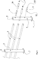
Figure 2 illustrates the various parts of the new barrier assembled. This figure also shows said terminal cross members (3a) with said relative closing elements (7), as well as said terminal connection elements (8). - The new barrier configured as described above has significant advantages.
- The new barrier absorbs shocks not only by means of the cross members (3) between the two uprights (2) between which the impact occurs, but also by means of the cross members (3) on the sides of the aforementioned two uprights (2).
- The new barrier makes it possible to absorb the impact not only through the cross members (3) on which the impact occurred, but also through the uprights (2) adjacent to the point of impact.
- In the case of damage to one or more cross members (3) and/or one or more uprights (2), it is very simple and quick to replace them as it is sufficient to remove the fixing elements (5) from the cross members (3) and from the connection elements (4) and, if necessary, detach the uprights (2) from the fixing elements (1) to the ground to replace the damaged cross members (3) and/or uprights (2).
- These specifications are sufficient for the expert person to construct the protection barrier of the invention, and as a result, in the practical application there may be variations without prejudice to the substance of the innovative concept.
- Therefore, with reference to the preceding description and the attached drawing the following claims are made.
Claims (10)
- Protection barrier comprising uprights (2) constituted by tubular section bars, cross members (3) constituted by tubular section bars and interposed between said uprights (2), fixing elements (1) suited to fix said uprights (2) to the ground, characterized in that each upright (2) is provided, on two opposite sides, with one or more aligned series of holes (2.2), and wherein each cross member (3) on one side of each upright (2) is connected to the corresponding cross member (3) aligned with it and positioned on the opposite side of said upright (2) through a connection element (4) passing through said holes (2.2) of said upright (2), in order to obtain mechanical continuity between two or more aligned cross members (3) positioned between said uprights (2).
- Protection barrier according to claim 1, characterized in that the cross section of said holes (2.2) of each upright (2) is identical to the outer cross section of each connection element (4).
- Protection barrier according to claim 1, characterized in that each cross member (3) is provided, in proximity to each one of its ends (3.1), with at least two opposite through holes (3.2), and wherein each connection element (4) is provided, in proximity to each one of its ends (4.1), with one or more opposite through holes (4.2) suited to be aligned with said holes (3.2) provided in said cross member (3) fitted on said connection element (4).
- Protection barrier according to the preceding claims, characterized in that it comprises one or more fixing elements (5) suited to constrain each end (3.1) of each cross member (3) to one end (4.1) of each connection element (4).
- Protection barrier according to the preceding claims, characterized in that said fixing elements (5) are suited to be inserted and locked in said holes (3.2) provided in said cross member (3) and at the same time in said holes (4.2) provided in the connection element (4) inserted in the end of the cross member (3) itself.
- Protection barrier according to the preceding claims, characterized in that it comprises a closing element (6) suited to be fitted on the top end (2.3) of each upright (2).
- Protection barrier according to the preceding claims, characterized in that it comprises terminal cross members (3a) suited to be fitted on the free ends (4.1) of the connection elements (4) of the two uprights (2) at the two ends of the barrier.
- Protection barrier according to claims 1, 2, 3, 4, 5, 6, characterized in that it comprises terminal connection elements (8), each terminal connection element (8) comprising:- a portion (8.1) having a cross section that is such that it can be fitted into said holes (2.2) of said upright (2) and be inserted in the end (3.1) of a cross member (3),- a terminal contact portion (8.2) that is larger than said holes (2.2) provided in said upright (2),and wherein on said portion (8.1) of said terminal connection element (8) there are two opposite through holes (4.2) suited to allow it to be joined to the fixing elements (5) of the cross members (3), and wherein each terminal connection element (8) is suited to be inserted in a hole (2.2) provided in said upright (2) and to be connected and joined to a cross member (3) on the opposite side of said upright (2) through one or more fixing elements (5).
- Protection barrier according to the preceding claims, characterized in that said uprights, said cross members and said connection elements are made of a plastic material.
- Protection barrier according to claim 9, characterized in that said uprights, said cross members and said connection elements are made of PVC.
Applications Claiming Priority (1)
| Application Number | Priority Date | Filing Date | Title |
|---|---|---|---|
| IT102019000023064A IT201900023064A1 (en) | 2019-12-05 | 2019-12-05 | PROTECTION BARRIER |
Publications (3)
| Publication Number | Publication Date |
|---|---|
| EP3832024A1 true EP3832024A1 (en) | 2021-06-09 |
| EP3832024C0 EP3832024C0 (en) | 2025-02-12 |
| EP3832024B1 EP3832024B1 (en) | 2025-02-12 |
Family
ID=70154912
Family Applications (1)
| Application Number | Title | Priority Date | Filing Date |
|---|---|---|---|
| EP20206904.3A Active EP3832024B1 (en) | 2019-12-05 | 2020-11-11 | Protection barrier |
Country Status (4)
| Country | Link |
|---|---|
| EP (1) | EP3832024B1 (en) |
| ES (1) | ES3015713T3 (en) |
| IT (1) | IT201900023064A1 (en) |
| PL (1) | PL3832024T3 (en) |
Cited By (1)
| Publication number | Priority date | Publication date | Assignee | Title |
|---|---|---|---|---|
| IT202400001422A1 (en) * | 2024-01-25 | 2025-07-25 | M P M S R L | ANTI-SHOCK DEVICE |
Citations (5)
| Publication number | Priority date | Publication date | Assignee | Title |
|---|---|---|---|---|
| US5577714A (en) * | 1995-03-27 | 1996-11-26 | Venegas, Jr.; Frank | Knock down guard rail assembly and method for assembling same |
| KR20100132721A (en) * | 2009-06-10 | 2010-12-20 | 대한민국(관리부서 : 산림청 국립산림과학원장) | Core wood reinforcement column and its manufacturing method |
| KR20120059683A (en) * | 2010-12-01 | 2012-06-11 | 주식회사 알엠앤에코 | Design fence for the implementstion of green growth |
| KR101434470B1 (en) * | 2013-10-31 | 2014-08-27 | 문중묵 | Wood fence using waste thinning trees and method for manufacturing thereof |
| WO2017168017A1 (en) * | 2016-04-01 | 2017-10-05 | Sistemas Tecnológicos De Nueva Generación Siglo Xxi, S. L. | Road safety barrier |
Family Cites Families (1)
| Publication number | Priority date | Publication date | Assignee | Title |
|---|---|---|---|---|
| KR100732916B1 (en) * | 2006-06-08 | 2007-06-28 | 주식회사 우전그린 | Safety light rail for road |
-
2019
- 2019-12-05 IT IT102019000023064A patent/IT201900023064A1/en unknown
-
2020
- 2020-11-11 ES ES20206904T patent/ES3015713T3/en active Active
- 2020-11-11 EP EP20206904.3A patent/EP3832024B1/en active Active
- 2020-11-11 PL PL20206904.3T patent/PL3832024T3/en unknown
Patent Citations (5)
| Publication number | Priority date | Publication date | Assignee | Title |
|---|---|---|---|---|
| US5577714A (en) * | 1995-03-27 | 1996-11-26 | Venegas, Jr.; Frank | Knock down guard rail assembly and method for assembling same |
| KR20100132721A (en) * | 2009-06-10 | 2010-12-20 | 대한민국(관리부서 : 산림청 국립산림과학원장) | Core wood reinforcement column and its manufacturing method |
| KR20120059683A (en) * | 2010-12-01 | 2012-06-11 | 주식회사 알엠앤에코 | Design fence for the implementstion of green growth |
| KR101434470B1 (en) * | 2013-10-31 | 2014-08-27 | 문중묵 | Wood fence using waste thinning trees and method for manufacturing thereof |
| WO2017168017A1 (en) * | 2016-04-01 | 2017-10-05 | Sistemas Tecnológicos De Nueva Generación Siglo Xxi, S. L. | Road safety barrier |
Cited By (2)
| Publication number | Priority date | Publication date | Assignee | Title |
|---|---|---|---|---|
| IT202400001422A1 (en) * | 2024-01-25 | 2025-07-25 | M P M S R L | ANTI-SHOCK DEVICE |
| EP4592453A1 (en) * | 2024-01-25 | 2025-07-30 | M.P.M. S.R.L. | A shock-resistant device |
Also Published As
| Publication number | Publication date |
|---|---|
| IT201900023064A1 (en) | 2021-06-05 |
| ES3015713T3 (en) | 2025-05-07 |
| EP3832024C0 (en) | 2025-02-12 |
| EP3832024B1 (en) | 2025-02-12 |
| PL3832024T3 (en) | 2025-05-12 |
Similar Documents
| Publication | Publication Date | Title |
|---|---|---|
| US3982735A (en) | Dismantable and directable rail or balustrade | |
| KR101605007B1 (en) | Railing structures | |
| KR101514350B1 (en) | Combination structure of angle rack | |
| EP3832024B1 (en) | Protection barrier | |
| KR20140105643A (en) | Coupling structure for beam to column connection | |
| KR102118831B1 (en) | Apparatus for a divisional strip | |
| KR101912226B1 (en) | H-Beam Reinforcement Apparatus | |
| KR101939178B1 (en) | Earthquake reinforcement device of masonry partition wall | |
| NO885211D0 (en) | Guardrails. | |
| KR101967361B1 (en) | Protective cover of Pagora pillars | |
| KR100993096B1 (en) | A lattice girder for tunnel construction | |
| KR101445570B1 (en) | Cabinet for electric and telecommunication equipment having seismic and anti-vibration performance | |
| KR100876098B1 (en) | Wood railing assembly structure | |
| KR20170037199A (en) | Assembly typed support frame for a table | |
| EP4321711B1 (en) | Kit for perimeter fencing | |
| KR101702221B1 (en) | Assembly style installations assemblies materials | |
| KR101611252B1 (en) | Frame modular construction | |
| KR101876511B1 (en) | Window seismic system using Steel Frame with Slit | |
| KR102527056B1 (en) | Assembly type safety fence | |
| KR101806303B1 (en) | A Safety Guard | |
| KR100812621B1 (en) | Frame assembly for fence | |
| US1703608A (en) | Manufacture of fencing, railings, or gates | |
| US3385566A (en) | Fence assembly | |
| KR101875476B1 (en) | Wooden Bridge Structure for Biosphere Preservation and a Construction Method Thereof | |
| KR101285250B1 (en) | Guard rod of window |
Legal Events
| Date | Code | Title | Description |
|---|---|---|---|
| PUAI | Public reference made under article 153(3) epc to a published international application that has entered the european phase |
Free format text: ORIGINAL CODE: 0009012 |
|
| STAA | Information on the status of an ep patent application or granted ep patent |
Free format text: STATUS: THE APPLICATION HAS BEEN PUBLISHED |
|
| AK | Designated contracting states |
Kind code of ref document: A1 Designated state(s): AL AT BE BG CH CY CZ DE DK EE ES FI FR GB GR HR HU IE IS IT LI LT LU LV MC MK MT NL NO PL PT RO RS SE SI SK SM TR |
|
| STAA | Information on the status of an ep patent application or granted ep patent |
Free format text: STATUS: REQUEST FOR EXAMINATION WAS MADE |
|
| 17P | Request for examination filed |
Effective date: 20211025 |
|
| RBV | Designated contracting states (corrected) |
Designated state(s): AL AT BE BG CH CY CZ DE DK EE ES FI FR GB GR HR HU IE IS IT LI LT LU LV MC MK MT NL NO PL PT RO RS SE SI SK SM TR |
|
| STAA | Information on the status of an ep patent application or granted ep patent |
Free format text: STATUS: EXAMINATION IS IN PROGRESS |
|
| 17Q | First examination report despatched |
Effective date: 20231127 |
|
| RIC1 | Information provided on ipc code assigned before grant |
Ipc: E04H 17/00 20060101ALI20240725BHEP Ipc: E04H 17/14 20060101ALI20240725BHEP Ipc: E01F 15/04 20060101AFI20240725BHEP |
|
| GRAP | Despatch of communication of intention to grant a patent |
Free format text: ORIGINAL CODE: EPIDOSNIGR1 |
|
| STAA | Information on the status of an ep patent application or granted ep patent |
Free format text: STATUS: GRANT OF PATENT IS INTENDED |
|
| GRAS | Grant fee paid |
Free format text: ORIGINAL CODE: EPIDOSNIGR3 |
|
| INTG | Intention to grant announced |
Effective date: 20241004 |
|
| RIN1 | Information on inventor provided before grant (corrected) |
Inventor name: MASON, LUCA |
|
| GRAA | (expected) grant |
Free format text: ORIGINAL CODE: 0009210 |
|
| STAA | Information on the status of an ep patent application or granted ep patent |
Free format text: STATUS: THE PATENT HAS BEEN GRANTED |
|
| AK | Designated contracting states |
Kind code of ref document: B1 Designated state(s): AL AT BE BG CH CY CZ DE DK EE ES FI FR GB GR HR HU IE IS IT LI LT LU LV MC MK MT NL NO PL PT RO RS SE SI SK SM TR |
|
| REG | Reference to a national code |
Ref country code: GB Ref legal event code: FG4D |
|
| REG | Reference to a national code |
Ref country code: CH Ref legal event code: EP |
|
| REG | Reference to a national code |
Ref country code: DE Ref legal event code: R096 Ref document number: 602020045846 Country of ref document: DE |
|
| REG | Reference to a national code |
Ref country code: IE Ref legal event code: FG4D |
|
| U01 | Request for unitary effect filed |
Effective date: 20250218 |
|
| U07 | Unitary effect registered |
Designated state(s): AT BE BG DE DK EE FI FR IT LT LU LV MT NL PT RO SE SI Effective date: 20250224 |
|
| PG25 | Lapsed in a contracting state [announced via postgrant information from national office to epo] |
Ref country code: RS Free format text: LAPSE BECAUSE OF FAILURE TO SUBMIT A TRANSLATION OF THE DESCRIPTION OR TO PAY THE FEE WITHIN THE PRESCRIBED TIME-LIMIT Effective date: 20250512 |
|
| PG25 | Lapsed in a contracting state [announced via postgrant information from national office to epo] |
Ref country code: IS Free format text: LAPSE BECAUSE OF FAILURE TO SUBMIT A TRANSLATION OF THE DESCRIPTION OR TO PAY THE FEE WITHIN THE PRESCRIBED TIME-LIMIT Effective date: 20250612 Ref country code: NO Free format text: LAPSE BECAUSE OF FAILURE TO SUBMIT A TRANSLATION OF THE DESCRIPTION OR TO PAY THE FEE WITHIN THE PRESCRIBED TIME-LIMIT Effective date: 20250512 |
|
| PG25 | Lapsed in a contracting state [announced via postgrant information from national office to epo] |
Ref country code: HR Free format text: LAPSE BECAUSE OF FAILURE TO SUBMIT A TRANSLATION OF THE DESCRIPTION OR TO PAY THE FEE WITHIN THE PRESCRIBED TIME-LIMIT Effective date: 20250212 |
|
| PG25 | Lapsed in a contracting state [announced via postgrant information from national office to epo] |
Ref country code: GR Free format text: LAPSE BECAUSE OF FAILURE TO SUBMIT A TRANSLATION OF THE DESCRIPTION OR TO PAY THE FEE WITHIN THE PRESCRIBED TIME-LIMIT Effective date: 20250513 |
|
| PG25 | Lapsed in a contracting state [announced via postgrant information from national office to epo] |
Ref country code: SM Free format text: LAPSE BECAUSE OF FAILURE TO SUBMIT A TRANSLATION OF THE DESCRIPTION OR TO PAY THE FEE WITHIN THE PRESCRIBED TIME-LIMIT Effective date: 20250212 |
|
| PG25 | Lapsed in a contracting state [announced via postgrant information from national office to epo] |
Ref country code: CZ Free format text: LAPSE BECAUSE OF FAILURE TO SUBMIT A TRANSLATION OF THE DESCRIPTION OR TO PAY THE FEE WITHIN THE PRESCRIBED TIME-LIMIT Effective date: 20250212 |
|
| PG25 | Lapsed in a contracting state [announced via postgrant information from national office to epo] |
Ref country code: SK Free format text: LAPSE BECAUSE OF FAILURE TO SUBMIT A TRANSLATION OF THE DESCRIPTION OR TO PAY THE FEE WITHIN THE PRESCRIBED TIME-LIMIT Effective date: 20250212 |
|
| PLBE | No opposition filed within time limit |
Free format text: ORIGINAL CODE: 0009261 |
|
| STAA | Information on the status of an ep patent application or granted ep patent |
Free format text: STATUS: NO OPPOSITION FILED WITHIN TIME LIMIT |
|
| U20 | Renewal fee for the european patent with unitary effect paid |
Year of fee payment: 6 Effective date: 20251126 |
|
| PGFP | Annual fee paid to national office [announced via postgrant information from national office to epo] |
Ref country code: GB Payment date: 20251127 Year of fee payment: 6 |
|
| 26N | No opposition filed |
Effective date: 20251113 |
|
| PGFP | Annual fee paid to national office [announced via postgrant information from national office to epo] |
Ref country code: PL Payment date: 20251021 Year of fee payment: 6 |
|
| PGFP | Annual fee paid to national office [announced via postgrant information from national office to epo] |
Ref country code: ES Payment date: 20251201 Year of fee payment: 6 |