EP3831999B1 - Drive system of washing machine and drum washing machine having same - Google Patents
Drive system of washing machine and drum washing machine having same Download PDFInfo
- Publication number
- EP3831999B1 EP3831999B1 EP18928409.4A EP18928409A EP3831999B1 EP 3831999 B1 EP3831999 B1 EP 3831999B1 EP 18928409 A EP18928409 A EP 18928409A EP 3831999 B1 EP3831999 B1 EP 3831999B1
- Authority
- EP
- European Patent Office
- Prior art keywords
- clutch
- drum
- pulsator
- washing machine
- drive system
- Prior art date
- Legal status (The legal status is an assumption and is not a legal conclusion. Google has not performed a legal analysis and makes no representation as to the accuracy of the status listed.)
- Active
Links
Images




Classifications
-
- D—TEXTILES; PAPER
- D06—TREATMENT OF TEXTILES OR THE LIKE; LAUNDERING; FLEXIBLE MATERIALS NOT OTHERWISE PROVIDED FOR
- D06F—LAUNDERING, DRYING, IRONING, PRESSING OR FOLDING TEXTILE ARTICLES
- D06F37/00—Details specific to washing machines covered by groups D06F21/00 - D06F25/00
- D06F37/30—Driving arrangements
- D06F37/304—Arrangements or adaptations of electric motors
-
- D—TEXTILES; PAPER
- D06—TREATMENT OF TEXTILES OR THE LIKE; LAUNDERING; FLEXIBLE MATERIALS NOT OTHERWISE PROVIDED FOR
- D06F—LAUNDERING, DRYING, IRONING, PRESSING OR FOLDING TEXTILE ARTICLES
- D06F37/00—Details specific to washing machines covered by groups D06F21/00 - D06F25/00
- D06F37/30—Driving arrangements
- D06F37/40—Driving arrangements for driving the receptacle and an agitator or impeller, e.g. alternatively
-
- H—ELECTRICITY
- H02—GENERATION; CONVERSION OR DISTRIBUTION OF ELECTRIC POWER
- H02K—DYNAMO-ELECTRIC MACHINES
- H02K7/00—Arrangements for handling mechanical energy structurally associated with dynamo-electric machines, e.g. structural association with mechanical driving motors or auxiliary dynamo-electric machines
- H02K7/003—Couplings; Details of shafts
-
- H—ELECTRICITY
- H02—GENERATION; CONVERSION OR DISTRIBUTION OF ELECTRIC POWER
- H02K—DYNAMO-ELECTRIC MACHINES
- H02K7/00—Arrangements for handling mechanical energy structurally associated with dynamo-electric machines, e.g. structural association with mechanical driving motors or auxiliary dynamo-electric machines
- H02K7/10—Structural association with clutches, brakes, gears, pulleys or mechanical starters
- H02K7/1004—Structural association with clutches, brakes, gears, pulleys or mechanical starters with pulleys
-
- H—ELECTRICITY
- H02—GENERATION; CONVERSION OR DISTRIBUTION OF ELECTRIC POWER
- H02K—DYNAMO-ELECTRIC MACHINES
- H02K7/00—Arrangements for handling mechanical energy structurally associated with dynamo-electric machines, e.g. structural association with mechanical driving motors or auxiliary dynamo-electric machines
- H02K7/10—Structural association with clutches, brakes, gears, pulleys or mechanical starters
- H02K7/108—Structural association with clutches, brakes, gears, pulleys or mechanical starters with friction clutches
-
- H—ELECTRICITY
- H02—GENERATION; CONVERSION OR DISTRIBUTION OF ELECTRIC POWER
- H02K—DYNAMO-ELECTRIC MACHINES
- H02K7/00—Arrangements for handling mechanical energy structurally associated with dynamo-electric machines, e.g. structural association with mechanical driving motors or auxiliary dynamo-electric machines
- H02K7/10—Structural association with clutches, brakes, gears, pulleys or mechanical starters
- H02K7/116—Structural association with clutches, brakes, gears, pulleys or mechanical starters with gears
-
- D—TEXTILES; PAPER
- D06—TREATMENT OF TEXTILES OR THE LIKE; LAUNDERING; FLEXIBLE MATERIALS NOT OTHERWISE PROVIDED FOR
- D06F—LAUNDERING, DRYING, IRONING, PRESSING OR FOLDING TEXTILE ARTICLES
- D06F37/00—Details specific to washing machines covered by groups D06F21/00 - D06F25/00
- D06F37/30—Driving arrangements
Definitions
- the present disclosure relates to the technical field of washing machines, and more particularly to a drive system of a washing machine and a drum washing machine having same.
- pulsators are generally arranged at the bottom of drums of the washing machines. During washing, the drums and the pulsators operate relatively at different speeds, and friction among the clothes can be increased, thereby improving the cleaning performance.
- a dual-power drum washing machine is disclosed in the related art, which is driven by an outer rotor DD (Direct Driver) motor (outer rotor linear motor).
- the rotor In the dual-power drum washing machine, the rotor is directly fixedly connected with a pulsator through a pulsator shaft and operates at the same speed; a sun gear fixedly connected to the pulsator shaft transmits power to a drum shaft in a constant speed ratio through a planetary gear, to realize operation of the pulsator and the drum in the same direction and at different speeds.
- this structure requires a split design of front and rear bearing brackets, a gear box is arranged between a front bearing and a rear bearing, and then the front bearing bracket and the rear bearing bracket are connected together by assembly.
- the dual-power drum washing machine in the related art generally fixes the rotor on the pulsator shaft which is a slender shaft and may cause problems such as insufficient rigidity.
- this design scheme completely changes the assembly method and connection relationship of a drive system of traditional drum washing machines, which is a great change to the design of the whole machine, and may have problems such as more parts, difficult assembly, and low axial space utilization.
- the outer rotor DD motor requires a large starting torque, and has a considerable difference in speed during washing and dewatering, causing high energy consumption and costs.
- KR 100 720 540 B1 is directed to an apparatus for driving a washing machine according to the preamble of claim 1.
- the washing machine has an outer tank, a washing tub and laundry wings.
- the washing tub and the laundry wings are rotatably installed within the outer tank.
- a motor is attached to the underside of the tank and drives via a belt a clutch pulley.
- the pulley is formed on an outer circumference of a gear housing. Depending on the position of the clutch, the pulley transmits a torque to shaft connected to the laundry wings and a transmission sleeve connected to the washing tub.
- Inside the gear housing a planetary gear is positioned.
- a sun gear is attached to the housing.
- the planetary wheels are rotatably attached to the shaft via a carrier and a gear ring that meshes with the planetary wheels is connected to the sleeve.
- the clutch is selectively movable by solenoid and compression spring. In a first state (solenoid is off) the clutch body connects the sleeve with the gear housing. In this position, the shaft and the sleeve rotate at the same speed. If the solenoid is energized, clutch body moves upwards and is coupled with the tank. In this state the sleeve is fixed to the tank, the gear housing is free to rotate and only the shaft is rotated. Due to the planetary gear, the shaft rotates by reduced speed.
- CN 106 757 995 A refers to a driving mechanism for a washing machine.
- the driving mechanism includes a variable-pole transformer, a planetary gear train connecting a motor and the washing machine barrel and a pulsator, a clutch assembly, and a mounting bracket.
- the variable-pole transformer includes a stator, a first rotor portion, and a second rotor portion.
- the planetary gear train includes a sun gear, a plurality of planetary gears, a ring gear, and a carrier.
- the input shaft is fixedly connected to the first rotor portion by splines.
- An output shaft is fixedly connected to the carrier of the planetary gear train and the other end of the output shaft is connected to a washing machine barrel.
- the ring gear is fixedly connected to the second rotor portion and to a dewatering sleeve that is connected with the barrel of the washing machine.
- the ring gear is provided with a clutch spline engaging with spline teeth of the clutch assembly.
- the clutch assembly includes a return spring and an electromagnetic coil. When the electromagnetic coil is energized, the clutch assembly is slid down along the splines of the gear ring and engages with the first rotor portion. The first rotor portion and the second rotor portion are thus coupled and the input shaft and the gear ring are integrally connected to synchronously rotate output shaft and dewatering sleeve.
- the clutch assembly When the electromagnetic coil is de-energized, the clutch assembly is urged upwards by the spring and thus engages with a mounting bracket to fix the second rotor portion.
- the second rotor portion and the stator simultaneously provide excitation to achieve a large torque output of the first rotor portion and to rotate the output shaft and the sleeve at different speeds.
- EP 3 278 983 B1 refers to a washing machine having a drum, a wing body located within the drum and a driving part.
- the driving part includes a driving motor, a first rotating shaft, a second rotating shaft, a bearing unit, a wing speed-reducing mechanism, a drum speed-reducing mechanism and a clutch mechanism.
- First rotating shaft has a sleeve form and the second rotating shaft extends through the first rotating shaft.
- the front part of the second rotating shaft is connected to the wing body and the front end of the first rotating shaft is connected to the drum.
- the speed-reducing mechanism includes wing belt wheel, a first motor belt wheel and a wing transmission belt.
- the drum speed-reducing mechanism includes drum belt wheel, a second motor belt wheel and a drum transmission belt.
- the clutch mechanism switches between a bi-axial driving form and a uni-axial driving form.
- the drum and the body rotate at different rotating speeds.
- the drum and the body rotate at the same rotating speed.
- the clutch couples the second rotating shaft with the wing belt wheel and in the uni-axial driving form the clutch couples the second rotating shaft with the drum belt wheel.
- the present disclosure aims to solve at least one of the problems existing in the related art. Therefore, the present disclosure provides a drive system of a washing machine according to claim 1.
- the drive system for the washing machine has low cost and energy consumption, good rigidity and strength, simple structure, and few design changes, is easy to assemble, and occupies a small axial space of the washing machine.
- the present disclosure also provides a washing machine having the above drive system.
- the washing machine includes the drive system, an outer tub, a drum, and a pulsator.
- the drum is rotatably arranged within the outer tub, and the pulsator is rotatably arranged at a bottom of the drum.
- the drive system includes: a pulsator shaft having a first end connected to the pulsator; a drum shaft sleeve fitted over an outer periphery of the pulsator shaft that is rotatable relative to the drum shaft sleeve, a first end of the drum shaft sleeve being connected to the drum; a bracket component, the drum shaft sleeve being arranged on the bracket component and rotatable relative to the bracket component, and the bracket component being connected to the outer tub; a motor; a belt transmission mechanism configured to transmit power of the motor to the drum shaft sleeve and drive the drum shaft sleeve to rotate; a gear transmission mechanism, through which a second end of the pulsator shaft is connected to the belt transmission mechanism; and a clutch mechanism configured to cooperate with one of the gear transmission mechanism and the bracket component, wherein in a configuration where the clutch mechanism cooperates with the gear transmission mechanism, the pulsator shaft and the drum shaft sleeve rotate synchronously; wherein in
- the motor for the washing machine according to embodiments of the present disclosure, by configuring the motor as an inner rotor motor, and transmitting the power of the motor to the inner gear ring through the belt and the belt pulley, on the premise of ensuring the starting torque of the washing machine, the cost and energy consumption of the motor can be reduced, which is advantageous to reducing the cost and energy consumption of the drive system.
- the belt pulley is connected to a second end of the drum shaft sleeve, which is advantageous to improving the rigidity of the drive system, and reducing the axial size of the drive system.
- the pulsator shaft and the drum shaft sleeve rotate synchronously; when the clutch mechanism cooperates with the bracket component, the pulsator shaft and the drum shaft sleeve rotate at different speeds.
- the pulsator shaft and the drum shaft sleeve can be switched between two modes of the synchronous rotation and the differential rotation, to allow the washing machine to adapt to clothes of different materials.
- the belt pulley has a central hole formed with a first spline portion on an inner peripheral wall of the central hole, the second end of the drum shaft sleeve has a belt pulley connecting portion fitted in the central hole, and the belt pulley connecting portion is formed with a second spline portion cooperating with the first spline portion.
- the bracket component includes a bearing bracket and a rear housing connected with each other; the bearing bracket is provided with a bearing fitted over an outer periphery of the drum shaft sleeve; the rear housing is arranged at an axial side of the bearing bracket; an accommodating space is defined between the bearing bracket and the rear housing; and the belt transmission mechanism, the gear transmission mechanism, and the clutch mechanism are located within the accommodating space.
- the bearing bracket is an integrally formed member.
- the rear housing is formed with an avoidance notch on an outer peripheral wall of the rear housing, and one end of the belt passes through the avoidance notch and is fitted over the outer peripheral side of the output shaft.
- the gear transmission mechanism includes: an inner gear ring connected to and arranged coaxially with the belt pulley, wherein when the clutch mechanism cooperates with the inner gear ring, the pulsator shaft and the drum shaft sleeve rotate synchronously; a sun gear connected to and arranged coaxially with the pulsator shaft, and located at an inner side of the inner gear ring; a planetary carrier component having a plurality of planetary gear shafts, and fitted over the outer periphery of the pulsator shaft and rotatable relative to the pulsator shaft; and a plurality of planetary gears rotatably fitted over the plurality of planetary gear shafts correspondingly, located between the inner gear ring and the sun gear, arranged around an outer periphery of the sun gear, and meshing with the inner gear ring and the sun gear.
- the plurality of planetary gears form one group, and each planetary gear directly meshes with the inner gear ring and the sun gear.
- the plurality of planetary gears form two groups meshing with each other, and one of the two groups of planetary gears meshes with the gear ring while the other group meshes with the sun gear.
- an inner peripheral wall of the second end of the drum shaft sleeve is formed with an avoidance groove penetrating an axial end face of the second end of the drum shaft sleeve, a part of the planetary carrier component is accommodated within the avoidance groove, and the planetary carrier component is spaced apart from the drum shaft sleeve.
- the inner gear ring is integrally formed on the belt pulley by injection molding.
- the clutch mechanism includes: a clutch sliding sleeve formed with a third spline portion on an inner peripheral wall of the clutch sliding sleeve, wherein the planetary carrier component includes a planetary carrier and a cover plate connected with each other; the inner gear ring is rotatably arranged between an outer peripheral wall of the planetary carrier and an inner peripheral wall of the cover plate; a mounting space is defined between the planetary carrier and the cover plate; the sun gear and the plurality of planetary gears are located within the mounting space; an outer peripheral wall of the cover plate is formed with a fourth spline portion cooperating with the third spline portion; and the clutch sliding sleeve is slidable between a first position and a second position along an axial direction relative to the cover plate; an electromagnetic coil component adapted to drive the clutch sliding sleeve to slide towards a first direction along the axial direction when the electromagnetic coil component is energized; and a clutch spring configured to drive the clutch sliding s
- the clutch spring is arranged between the bracket component and the clutch sliding sleeve.
- the clutch spring is arranged between the belt pulley and the clutch sliding sleeve.
- a first axial end face of the clutch sliding sleeve is formed with a plurality of first clutch teeth arranged along a peripheral direction; the inner gear ring is formed with a plurality of second clutch teeth meshing with the plurality of first clutch teeth; a second axial end face of the clutch sliding sleeve is formed with a plurality of third clutch teeth arranged along the peripheral direction; and the bracket component is formed with a plurality of fourth clutch teeth meshing with the plurality of third clutch teeth.
- the first clutch teeth and the third clutch teeth are each formed in a step shape in the axial direction of the clutch sliding sleeve.
- a drum washing machine includes: an outer tub; a drum rotatably arranged within the outer tub; a pulsator rotatably arranged at a bottom of the drum; and the above drive system, wherein the first end of the pulsator shaft is connected to the pulsator, the first end of the drum shaft sleeve is connected to the drum, and the bracket component is connected to the outer tub.
- the drum washing machine by providing the above drive system, and in turn by configuring the motor as the inner rotor motor and transmitting the power of the motor to the inner gear ring by the belt and the belt pulley, on the premise of ensuring the starting torque of the washing machine, the cost and energy consumption of the motor can be reduced, which is advantageous to reducing the cost and energy consumption of the drive system.
- the belt pulley is connected to the second end of the drum shaft sleeve, which is advantageous to improving the rigidity of the drive system, and reducing the axial size of the drive system.
- the pulsator shaft and the drum shaft sleeve rotate synchronously; when the clutch mechanism cooperates with the bracket component, the pulsator shaft and the drum shaft sleeve rotate at different speeds.
- the pulsator shaft and the drum shaft sleeve can be switched between two modes of the synchronous rotation and the differential rotation, to allow the washing machine to adapt to clothes of different materials.
- a drive system 10 of a washing machine 100 will be described below with reference to FIGS. 1 to 11 .
- the washing machine 100 includes the drive system 10, an outer tub 20, a drum 30, and a pulsator 40.
- the drum 30 is rotatably arranged within the outer tub 20, and the pulsator 40 is rotatably arranged at a bottom of the drum 30, wherein the bottom of the drum 30 is opposite to an opening of the drum 30.
- the drum 30 has a washing chamber therein, a front of the washing chamber is formed with an opening, and the pulsator 40 is rotatably arranged at a rear of the washing chamber.
- the drive system 10 can include a pulsator shaft 1, a drum shaft sleeve 2, a bracket component 3, a motor 4, a belt transmission mechanism 5, a gear transmission mechanism 6, and a clutch mechanism 7.
- a first end of the pulsator shaft 1 (for example, a front end illustrated in FIG. 3 ) is adapted to be connected to the pulsator 40; the drum shaft sleeve 2 is fitted over an outer periphery of the pulsator shaft 1; the pulsator shaft 1 is rotatable relative to the drum shaft sleeve 2 to drive the pulsator 40 to rotate; a first end of the drum shaft sleeve 2 (for example, a rear end illustrated in FIG. 3 ) is adapted to be connected to the drum 30; and the drum shaft sleeve 2 can drive the drum 30 to rotate.
- the drum shaft sleeve 2 is arranged on the bracket component 3 and is rotatable relative to the bracket component 3; the bracket component 3 is adapted to be connected to the outer tub 20; the motor 4 is an inner rotor motor and is adapted to be connected to the outer tub 20. Therefore, it is advantageous to reducing the cost and energy consumption of the motor 4.
- the motor 4 is a BLDC inner rotor motor (brushless direct current inner rotor motor).
- the belt transmission mechanism 5 includes a belt pulley 51 and a belt 52.
- One end of the belt 52 is fitted over an outer peripheral side of an output shaft 41 of the motor 4, while the other end of the belt 52 is fitted over an outer peripheral side of the belt pulley 51.
- the belt pulley 51 is connected to a second end of the drum shaft sleeve 2.
- a second end of the pulsator shaft 1 is connected to the belt transmission mechanism 5 through the gear transmission mechanism 6.
- the belt transmission mechanism 5 transmits power of the motor 4 to the drum shaft sleeve 2 to drive the drum shaft sleeve 2 to rotate; at the same time, the belt transmission mechanism 5 transmits the power of the motor 4 to the gear transmission mechanism 6, and in turn to the pulsator shaft 1 through the gear transmission mechanism 6, thereby driving the pulsator shaft 1 to rotate.
- the pulsator shaft 1 is a slender shaft, and a diameter of the drum shaft sleeve 2 is greater than a diameter of the pulsator shaft 1.
- the rigidity of the drive system 10 can be enhanced, and the belt pulley 51 occupies a smaller space in a length direction of the pulsator shaft 1 than the motor 4, which is advantageous to reducing an axial size of the drive system 10.
- the power of the motor 4 is transmitted to the gear transmission mechanism 6 through the belt 52 and the belt pulley 51, which can reduce the rotation speed and increase the torque, thereby ensuring a starting torque of the washing machine 100.
- the clutch mechanism 7 selectively cooperates with one of the gear transmission mechanism 6 and the bracket component 3.
- the clutch mechanism 7 cooperates with the gear transmission mechanism 6, the pulsator shaft 1 and the drum shaft sleeve 2 rotate synchronously.
- the clutch mechanism 7 cooperates with the bracket component 3, the pulsator shaft 1 and the drum shaft sleeve 2 rotate at different speeds.
- the synchronous rotation of the pulsator shaft 1 and the drum shaft sleeve 2 means that the pulsator shaft 1 and the drum shaft sleeve 2 rotate in the same direction and at the same angular speed
- “differential rotation of the pulsator shaft 1 and the drum shaft sleeve 2” means that the pulsator shaft 1 and the drum shaft sleeve 2 rotate at different angular speeds, wherein the differential rotation can be in the same direction or in the opposite directions. Therefore, the pulsator shaft 1 and drum shaft sleeve 2 can be switched between one washing mode of the synchronous rotation and another washing mode of the differential rotation.
- washing machine 100 In a washing condition, by controlling whether the pulsator shaft 1 and the drum shaft sleeve 2 rotate at different speeds, it is possible to control whether the drum 30 and the pulsator 40 rotate at different speeds (i.e., switching between a dual-output washing mode and a single-output washing mode), such that the washing machine 100 can adapt to clothes of different materials. For example, during washing, the washing machine 100 can be switched to the single-output washing state (with the pulsator shaft 1 and the drum shaft sleeve 2 rotating synchronously), and in such a case, the washing machine 100 has the advantage of not damaging the clothes, and can wash clothes that need gentle washing such as cashmere or silk.
- the washing machine 100 When the washing machine 100 is switched to the dual-output washing state (with the pulsator shaft 1 and the drum shaft sleeve 2 rotating differentially), the washing machine 100 has a strong washing capacity, and can wash clothes with stubborn stains or clothes made of washable materials.
- the motor 4 As the inner rotor motor, and transmitting the power of the motor 4 to the inner gear ring 61 through the belt 52 and the belt pulley 51, on the premise of ensuring the starting torque of the washing machine 100, the cost and energy consumption of the motor 4 can be reduced, which is advantageous to reducing the cost and energy consumption of the drive system 10.
- the belt pulley 51 is connected to the second end of the drum shaft sleeve 2, which is advantageous to improving the rigidity of the drive system 10, and reducing the axial size of the drive system.
- the pulsator shaft 1 and the drum shaft sleeve 2 rotate synchronously; when the clutch mechanism 7 cooperates with the bracket component 3, the pulsator shaft 1 and the drum shaft sleeve 2 rotate at different speeds.
- the pulsator shaft 1 and the drum shaft sleeve 2 can be switched between two modes of the synchronous rotation and the differential rotation, to allow the washing machine 100 to adapt to clothes of different materials.
- the belt pulley 51 has a central hole 511 with a first spline portion 512 formed on an inner peripheral wall of the central hole 511.
- the second end of the drum shaft sleeve 2 has a belt pulley connecting portion 21 fitted in the central hole 511, and the belt pulley connecting portion 21 is formed with a second spline portion 211 cooperating with the first spline portion 512.
- the bracket component 3 includes a bearing bracket 31 and a rear housing 32 connected with each other.
- the bearing bracket 31 is provided with a bearing thereon, and the bearing is fitted over an outer periphery of the drum shaft sleeve 2.
- the rear housing 32 is arranged at an axial side of the bearing bracket 31.
- An accommodating space is defined between the bearing bracket 31 and the rear housing 32, and the belt transmission mechanism 5, the gear transmission mechanism 6, and the clutch mechanism 7 are located within the accommodating space. Therefore, the belt transmission mechanism 5, the gear transmission mechanism 6, and the clutch mechanism 7 are isolated from the external environment, which is beneficial to improving the operational stability of the belt transmission mechanism 5, the gear transmission mechanism 6, and the clutch mechanism 7.
- the bearing bracket 31 is fixedly connected to the outer tub 20, and a front end and a rear end of an inner hole of the bearing bracket are provided with a first bearing chamber 311 and a second bearing chamber 312, respectively.
- Outer rings of a first bearing 86 and a second bearing 87 are fixedly mounted within the first bearing chamber 311 and the second bearing chamber 312, respectively.
- the drum shaft sleeve 2 is rotatably mounted in the inner hole of the bearing bracket 31 through the first bearing 86 and the second bearing 87.
- the rear end of the drum shaft sleeve 2 is provided with the belt pulley connecting portion 21.
- the belt pulley 51 with an opening backward is fixedly connected to the belt pulley connecting portion 21.
- the drum shaft sleeve 2 is of a hollow structure. Referring to FIGS. 1 and 11 , the pulsator shaft 1 is rotatably arranged in the drum shaft sleeve 2 through a first bushing 81 and a second bushing 82 press-fitted in an inner hole of the drum shaft sleeve 2.
- the bearing bracket 31 is an integrally formed member. Therefore, it is beneficial to improving the supporting rigidity of the bearing bracket 31.
- the drum shaft sleeve 2 is a hollow rotating structure; an outer peripheral wall of the drum shaft sleeve 2 is provided with a drum connecting portion 22, a large oil seal connecting portion 23, a bearing mounting portion 24, and a belt pulley connecting portion 21 in sequence from front to rear; and the inner hole of the drum shaft sleeve 2 is provided with a small oil seal mounting portion 25, a first bushing mounting portion 26, a second bushing mounting portion 27, and an avoidance groove 28 in sequence from front to rear.
- the drum shaft sleeve 2 is fitted into a bearing hole from an end of the first bearing 86; the bearing mounting portion 24 is mounted in inner holes of the first bearing 86 and the second bearing 87, so that the drum shaft sleeve 2 is rotatably mounted within the bearing bracket 31; a front end of the drum shaft sleeve 2 is fixedly connected to the drum 30 through the drum connecting portion 22, and the belt pulley connecting portion 21 located at the rear end of the drum shaft sleeve 2 is fixedly connected to the belt pulley 51.
- the pulsator shaft 1 is provided with a pulsator connecting portion 11, a small oil seal connecting portion 12, a bushing mounting portion 13, a first shaft shoulder 14, and a second shaft shoulder 15 in sequence from front to rear.
- the pulsator shaft 1 is rotatably supported in the inner hole of the drum shaft sleeve 2 through the first bushing 81 and the second bushing 82, and the pulsator shaft 1 is forwardly limited to the second bushing 82 by the first shaft shoulder 14.
- a side of the pulsator shaft 1 where the first bushing 81 is exposed is equipped with an adjusting washer 93 for adjusting a axial movement between the pulsator shaft 1 and the drum shaft sleeve 2.
- the pulsator shaft 1 is backwardly limited to the first bushing 81 by an elastic retaining ring 94 arranged at a front end of the adjusting washer 93.
- the front end of the pulsator shaft 1 is fixedly connected to the pulsator 40 through the pulsator connecting portion 11, and a rear end of the pulsator shaft 1 is fixedly connected with a sun gear 62 and limited to the second shaft shoulder 15. Therefore, the operation of the pulsator shaft 1 can be made stable and reliable.
- seals are provided among the bearing bracket 31, the drum shaft sleeve 2, and the pulsator shaft 1, and the seals include a large water seal 91 and a small water seal 92.
- the large water seal 91 is fixedly mounted in an inner hole of a front end of the bearing bracket 31 and is inwardly sealed and connected with the drum shaft sleeve 2.
- the small water seal 92 is fixedly mounted in an inner hole of the front end of the drum shaft sleeve 2 and is inwardly sealed and connected with the pulsator shaft 1. Specifically, as illustrated in FIG.
- the large water seal 91 is fixed at the front end of the bearing bracket 31, and a first sealing lip 911 is provided in the inner hole of the bearing bracket 31 and abuts against the large oil seal connecting portion 23 of the drum shaft sleeve 2; an outer ring of the small water seal 92 is fixedly connected to the small oil seal mounting portion 25 of the drum shaft sleeve 2, and the small water seal 92 is inwardly provided with a third sealing lip 921 which abuts against the small oil seal connecting portion 12 of the pulsator shaft 1.
- an outer peripheral wall of the rear housing 32 is formed with an avoidance notch 321, and one end of the belt 52 passes through the avoidance notch 321 and is fitted over the outer peripheral side of the output shaft 41. Therefore, by providing the avoidance notch 321, it is convenient for two ends of the belt 52 to be connected to the output shaft 41 and the belt pulley 51 respectively, and interference between the belt 52 and the rear housing 32 can be avoided.
- the motor 4 is fixedly connected to the outer tub 20, and a shaft of the motor 4 is parallel to the pulsator shaft 1; one end of the belt 52 is fitted over the outer peripheral side of the output shaft 41 of the motor 4, while the other end of the belt 52 is fitted over the outer peripheral side of the belt pulley 51; the rear housing 32 with an opening forward is fixedly connected to a rear end face of the bearing bracket 31 and fitted over the belt 52 without contact; one side of the rear housing 32 is provided with the avoidance notch 321 adapted to avoid the belt 52, and the belt 52 passes through the avoidance notch 321 and is connected to the motor 4.
- the gear transmission mechanism 6 includes: an inner gear ring 61, a sun gear 62, a planetary carrier component 63, and a planetary gear 64.
- the inner gear ring 61 is connected to and arranged coaxially with the belt pulley 51.
- the clutch mechanism 7 cooperates with the inner gear ring 61, the pulsator shaft 1 and the drum shaft sleeve 2 rotate synchronously.
- the sun gear 62 is connected to and arranged coaxially with the pulsator shaft 1, and the sun gear 62 is located at an inner side of the inner gear ring 61.
- the planetary carrier component 63 has a plurality of planetary gear shafts 6315, and the planetary carrier component 63 is fitted over the outer periphery of the pulsator shaft 1 and is rotatable relative to the pulsator shaft 1.
- a plurality of the planetary gears 64 are provided and rotatably fitted over the plurality of planetary gear shafts 6315 correspondingly.
- the plurality of the planetary gears 64 are located between the inner gear ring 61 and the sun gear 62 and arranged around an outer periphery of the sun gear 62.
- the planetary gears 64 mesh with the inner gear ring 61 and the sun gear 62.
- the planetary carrier component 63 is fixedly connected to the inner gear ring 61, so that the inner gear ring 61, the planetary carrier component 63, the planetary gear 64, the sun gear 62, and the pulsator shaft 1 run at the same angular speed. Moreover, since both the inner gear ring 61 and the drum shaft sleeve 2 are connected to and arranged coaxially with the belt pulley 51, the pulsator shaft 1 and the drum shaft sleeve 2 rotate synchronously.
- the belt transmission mechanism 5 transmits the power of the motor 4 to the drum shaft sleeve 2 to drive the drum shaft sleeve 2 to rotate.
- the belt transmission mechanism 5 transmits the power of the motor 4 to the inner gear ring 61, and in turn the inner gear ring 61 drives the planetary gear 64 to rotate around the planetary gear shaft 6315; the planetary gear 64 drives a central gear to rotate, and the central gear drives the pulsator shaft 1 to rotate; the pulsator shaft 1 and the drum shaft sleeve 2 rotate at different speeds.
- the structure is simple, and it is convenient for the pulsator shaft 1 and the drum shaft sleeve 2 to realize the synchronous rotation and the differential rotation.
- the plurality of planetary gears 64 form a group, and each planetary gear 64 directly meshes with the inner gear ring 61 and the sun gear 62. Therefore, when the clutch mechanism 7 cooperates with the bracket component 3, the pulsator shaft 1 and the drum shaft sleeve 2 can rotate in reverse directions and at different speeds.
- the plurality of planetary gears 64 form two groups that mesh with each other.
- One of the two groups of the planetary gears 64 meshes with the inner gear ring 61, and the other group meshes with the sun gear 62. Therefore, when the clutch mechanism 7 cooperates with the bracket component 3, the pulsator shaft 1 and the drum shaft sleeve 2 rotate in the same direction and at different speeds.
- the plurality of planetary gears 64 are divided into a first group of planetary gears and a second group of planetary gears; the first group of planetary gears are arranged adjacent to a center of the inner gear ring 61 and mesh with the sun gear 62; the second group of planetary gears are arranged away from the center of the inner gear ring 61 and mesh with the inner gear ring 61 and the first group of planetary gears.
- an inner peripheral wall of the second end of the drum shaft sleeve 2 is formed with the avoidance groove 28 that penetrates an axial end face of the second end of the drum shaft sleeve 2, a part of the planetary carrier component 63 is accommodated in the avoidance groove 28, and the planetary carrier component 63 is spaced from the drum shaft sleeve 2. Therefore, it is beneficial to reducing the axial size of the drive system 10.
- the inner gear ring 61 is integrally formed on the belt pulley 51 by injection molding. Therefore, an integrated injection molding structure can not only ensure the structure and performance stability of the inner gear ring 61 and the belt pulley 51, but also omit redundant assembly parts and connection processes, the efficiency of assembly between the inner gear ring 61 and the belt pulley 51 can be improved greatly, and the reliability of connection between the inner gear ring 61 and the belt pulley 51 can be ensured.
- the clutch mechanism 7 includes a clutch sliding sleeve 71, an electromagnetic coil component 72, and a cultch spring 73.
- An inner peripheral wall of the clutch sliding sleeve 71 is formed with a third spline portion 711.
- the planetary carrier component 63 includes a planetary carrier 631 and a cover plate 632 connected to each other.
- the inner gear ring 61 is rotatably arranged between an outer peripheral wall of the planetary carrier 631 and an inner peripheral wall of the cover plate 632.
- a mounting space is defined between the planetary carrier 631 and the cover plate 632, and the sun gear 62 and the plurality of planetary gears 64 are located in the mounting space.
- An outer peripheral wall of the cover plate 632 is formed with a fourth spline portion 6321 cooperating with the third spline portion 711.
- the clutch sliding sleeve 71 is slidable between a first position and a second position along an axial direction relative to the cover plate 632.
- the clutch sliding sleeve 71 cannot rotate relative to the cover plate 632, so that the sliding of the clutch sliding sleeve 71 between the first position and the second position along the axial direction is stable and reliable.
- the planetary carrier 631 and the cover plate 632 are fixedly connected by a support column 6311 and a support column through-hole 6323.
- the electromagnetic coil component 72 when the electromagnetic coil component 72 is energized, the electromagnetic coil component 72 is adapted to drive the clutch sliding sleeve 71 to slide towards a first direction (for example, a front direction as illustrated in FIG. 1 ) along the axial direction, and the clutch spring 73 is used to drive the clutch sliding sleeve 71 to slide towards a second direction (for example, a rear direction as illustrated in FIG. 1 ) opposite to the first direction.
- a first direction for example, a front direction as illustrated in FIG. 1
- the clutch spring 73 is used to drive the clutch sliding sleeve 71 to slide towards a second direction (for example, a rear direction as illustrated in FIG. 1 ) opposite to the first direction.
- the clutch sliding sleeve 71 cooperates with the carrier assembly 3. Therefore, the sliding of the clutch sliding sleeve 71 can be stable and reliable, and when the clutch sliding sleeve 71 cooperates with the inner gear ring 61, the synchronous rotation of the pulsator shaft 1 and the drum shaft sleeve 2 can be realized; when the clutch sliding sleeve 71 cooperates with the carrier assembly 3, the differential rotation of the pulsator shaft 1 and the drum shaft sleeve 2 can be realized.
- the clutch sliding sleeve 71 includes a non-magnetically conductive tooth-shaped member 714 and a magnetically conductive sleeve 715 cooperating with each other in a radial direction and integrally formed, and the magnetically conductive sleeve 715 is arranged on an outer ring of the non-magnetically conductive tooth-shaped member 714.
- An outer ring of the cover plate 632 is fixedly provided with the fourth spline portion 6321, and the clutch sliding sleeve 71 is axially slidably fitted over an outer side of the fourth spline portion 6321 of the cover plate 632 through the third spline portion 711 arranged fixedly on the inner hole.
- Both ends of the non-magnetically conductive tooth-shaped member 714 are provided with first clutch teeth 712 and third clutch teeth 713.
- An end face of the inner gear ring 61 facing away from a gear part is integrally provided with an annular flange 612, and one side of the flange 612 facing the gear transmission mechanism 6 is fixedly provided with second clutch teeth 611 distributed uniformly along a peripheral direction.
- the second clutch teeth 611 and the inner gear ring 61 are integrally formed by injection molding, and fourth clutch teeth 322 and the rear housing 32 are integrally formed by injection molding.
- the planetary carrier 631 and the cover plate 632 have hollow structures, and a third bushing 83 and a fourth bushing 84 are fixedly arranged in inner holes of the planetary carrier and the cover plate.
- the planetary carrier and the cover plate are rotatably fitted over the pulsator shaft 1 without contact, through the third bushing 83 and the fourth bushing 84.
- the sun gear 62 is arranged between the third bushing 83 and the fourth bushing 84.
- the third bushing mounting portion 6312 integrally arranged with the planetary carrier 631 is inserted into the avoidance groove 28 of the drum shaft sleeve 2 and axially limited to the first shaft shoulder 14.
- the double-end support can enhance the connection rigidity of the whole gear transmission mechanism 6, and avoid insufficient rigidity caused by the single-side support, thereby reducing washing noise, and improving the stability of the whole machine.
- the axial size can be reduced by the arrangement of the avoidance groove 28.
- the planetary carrier component 63 includes the planetary carrier 631 and the cover plate 632 fixedly connected to each other.
- the plurality of planetary gear shafts 6315 are distributed between the planetary carrier 631 and the cover plate 632 along the peripheral direction.
- the inner gear ring 61 is coaxially fixed to the belt pulley 51.
- the cover plate 632 has a cuplike structure, and the planetary carrier 632 is located within the cuplike structure.
- the inner gear ring 61 is arranged between an outer ring of the planetary carrier 631 and an inner wall of the cover plate 632, and an inner peripheral wall of the inner gear ring 61 meshes with the planetary gear 64.
- first mounting holes 6313 and several second mounting holes 6322 are distributed between the planetary carrier 631 and the cover plate 632 along the peripheral direction respectively, and the first mounting holes 6313 and the second mounting holes 6322 are arranged correspondingly, between which several planetary gear shafts 6315 are mounted.
- the planetary gear 64 is fitted over the planetary gear shaft 6315 without contact and inwardly meshes with the sun gear 62 for transmission.
- the cover plate 632 has a cuplike structure, and the planetary carrier 631 is located within the cuplike structure.
- the inner gear ring 61 is coaxially arranged between the outer ring of the planetary carrier 631 and the inner wall of the cover plate 632, and inner teeth of the inner gear ring 61 mesh with the planetary gear 6412 for transmission.
- the outer ring of the planetary carrier 631 is integrally provided with a first oil stopper 6314 projecting outwardly in an annular shape
- an inner ring of the inner gear ring 61 is integrally provided with a second oil stopper 615 projecting inwardly in an annular shape.
- a gap between the first oil stopper 6314 and the second oil stopper 615 does not exceed 1 mm.
- the second oil stopper 615, the first oil stopper 6314, the cover plate 632, and a body of the inner gear ring 61 form a labyrinth structure to prevent grease in the gear transmission mechanism 6 from splashing during operation.
- the clutch spring 73 is arranged between the bracket component 3 and the clutch sliding sleeve 71. It should be noted that when the washing machine 100 is in a non-working state, the clutch sliding sleeve 71 cooperates with the inner gear ring 61, the clutch spring 73 is compressed, and the clutch sliding sleeve 71 is at a dewatering station.
- the electromagnetic coil component 72 is energized, and the clutch sliding sleeve 71 moves towards a direction away from the inner gear ring 61 under an electromagnetic force and compresses the clutch spring 73 is compressed, such that the clutch sliding sleeve 71 cooperates with the bracket component 3, the planetary carrier component 63 is braked, the gear transmission mechanism 6 becomes a shaft-fixed gear train, and the pulsator shaft 1 and the drum shaft sleeve 2 rotate at different speeds.
- the electromagnetic coil component 72 is de-energized, the clutch sliding sleeve 71 is reset under the action of the clutch spring 73, and the clutch sliding sleeve 71 enters into cooperation with the inner gear ring 61, in which case the planetary carrier component 63 is fixedly connected with the inner gear ring 61, and the whole gear transmission mechanism 6 operates at the same speed, such that the pulsator shaft 1 and the drum shaft sleeve 2 rotate synchronously. Therefore, the electromagnetic coil component 72 is not energized in a dewatering mode, thereby avoiding damage caused by collision between the clutch sliding sleeve 71 and the inner gear ring 61 in case of power down during dewatering.
- the clutch sliding sleeve 71 is provided with a spring mounting portion 716, and the clutch spring 73 is arranged between the spring mounting portion 716 and the rear housing 32.
- the clutch spring 73 is arranged between the belt pulley 51 and the clutch sliding sleeve 71. It should be noted that when the washing machine 100 is in a non-working state, the clutch sliding sleeve 71 cooperates with the bracket component 3, the clutch spring 73 is compressed, and the clutch sliding sleeve 71 is at a washing station.
- the electromagnetic coil component 72 is energized, and the clutch sliding sleeve 71 moves towards a direction away from the bracket component 3 under an electromagnetic force and compresses the clutch spring 73, such that the clutch sliding sleeve 71 cooperates with the inner gear ring 61, in which case the planetary carrier component 63 is fixedly connected with the inner gear ring 61, and the whole gear transmission mechanism 6 operates at the same speed, such that the pulsator shaft 1 and the drum shaft sleeve 2 rotate synchronously.
- the electromagnetic coil component 72 is de-energized, the clutch sliding sleeve 71 is reset under the action of the clutch spring 73, and the clutch sliding sleeve 71 enters into cooperation with the bracket component 3; the planetary carrier component 63 is braked; the gear transmission mechanism 6 becomes a shaft-fixed gear train; and the pulsator shaft 1 and the drum shaft sleeve 2 rotate at different speeds. Therefore, during washing, the electromagnetic coil component 72 is not energized, thereby reducing the energy consumption of the washing machine 100.
- the clutch sliding sleeve 71 is provided with a spring mounting portion 716, and the clutch spring 73 is arranged between the spring mounting portion 716 and the belt pulley 51.
- a first axial end face of the clutch sliding sleeve 71 is formed with a plurality of first clutch teeth 712 arranged along the peripheral direction, and the inner gear ring 61 is formed with the second clutch teeth 611 meshing with the plurality of first clutch teeth 712; a second axial end face of the clutch sliding sleeve 71 is formed with a plurality of third clutch teeth 713 arranged along the peripheral direction, and the bracket component 3 is formed with the fourth clutch teeth 322 meshing with the plurality of third clutch teeth 713.
- the first clutch teeth 712 and the third clutch teeth 713 are formed in a step shape in an axial direction of the clutch sliding sleeve 71. Therefore, on the one hand, it is beneficial to increasing a meshing area between the first clutch teeth 712 and the second clutch teeth 611, to further improve the reliability of cooperation between the clutch sliding sleeve 71 and the inner gear ring 61; on the other hand, the step-shaped teeth mesh easily, a total height of the teeth is small, and the clutching reliability and the compression of axial height can be controlled effectively.
- first clutch teeth 712 and the third clutch teeth 713 each consist of first straight teeth and second straight teeth, the first straight teeth and the second straight teeth are perpendicular to each other, and projections of the first clutch teeth 712 and the third clutch teeth 713 in the axial direction are all step-like.
- a fifth bushing 85 is mounted in an inner hole of the rear housing 32, and the planetary carrier component 63 is pivotally mounted in an inner hole of the fifth bushing 85 through a fourth bushing mounting portion 6324.
- the first bushing 81 to the fifth bushing 85 are all made of oil-retaining bearing materials.
- a drum washing machine 100 includes: an outer tub 20, a pulsator 40, a drum 30, and the above drive system 10.
- the drum is rotatably arranged within the outer tube 20.
- the pulsator 40 is rotatably arranged at a bottom of the drum 30.
- a first end of the pulsator shaft 1 is connected with the pulsator 40.
- a first end of the drum shaft sleeve 2 is connected with the drum 30.
- the bracket component 3 is connected with the outer tub 20.
- the motor 4 is connected with the outer tube 20.
- the drum washing machine 100 by providing the above drive system 10, and in turn by configuring the motor 4 as the inner rotor motor and transmitting the power of the motor 4 to the inner gear ring 61 by the belt 52 and the belt pulley 51, on the premise of ensuring the starting torque of the washing machine 100, the cost and energy consumption of the motor 4 can be reduced, which is advantageous to reducing the cost and energy consumption of the drive system 10.
- the belt pulley 51 is connected to the second end of the drum shaft sleeve 2, which is advantageous to improving the rigidity of the drive system 10, and reducing the axial size of the drive system.
- the pulsator shaft 1 and the drum shaft sleeve 2 rotate synchronously; when the clutch mechanism 7 cooperates with the bracket component 3, the pulsator shaft 1 and the drum shaft sleeve 2 rotate at different speeds.
- the pulsator shaft 1 and the drum shaft sleeve 2 can be switched between two modes of the synchronous rotation and the differential rotation, to allow the washing machine 100 to adapt to clothes of different materials.
- the motor 4 transmits the power to the inner gear ring 61 through the belt pulley 52 in a speed-decreasing and distance-increasing manner
- the inner gear ring 61 transmits the power to the sun gear 62 through the planetary gear in a speed-increasing and distance-decreasing manner
- the sun gear 62 and the inner gear ring 61 drive the pulsator 40 and the drum 30 to operate at different speeds through the drum shaft sleeve 2 and the pulsator shaft 1 respectively.
- the drum washing machine 100 can switch between a dual-output mode and a single-output mode. It should be noted that by controlling whether the pulsator 40 and the drum 30 are in a differential speed operation state during washing, the purpose of switching between the single-output washing mode and the dual-output washing mode can be realized, thereby achieving a drum washing machine 100 that can switch between the single-output washing mode and the dual-output washing mode according to washing requirements, and enabling the drum washing machine 100 to adapt to clothes of different materials.
- the dual-output mode is as follows: under a washing condition, the motor 4 runs at a low speed; the clutch mechanism 7 cooperates with the bracket component 3; the belt pulley 51 drives the drum 30 to operate at a constant speed ratio and drives the pulsator 40 to operate through the gear transmission mechanism 6; the pulsator shaft 1 and the drum shaft sleeve 2 rotate at different speeds; a speed ratio of the pulsator 40 to the drum 30 is a transmission ratio of the gear transmission mechanism 6, in which case the washing machine 100 is in a dual-output washing state and has a strong cleaning ability to wash stubborn stains or clothes made of washable materials.
- the motor 4 runs at a high speed; the clutch mechanism 7 cooperates with the gear transmission mechanism 6; the pulsator shaft 1 and the drum shaft sleeve 2 rotate synchronously; the pulsator 40 and the drum 30 are driven by the motor 4 through the belt pulley 51 to operate at the same high speed.
- the single-output mode is as follows: under a washing condition, the motor 4 runs at a low speed; the clutch mechanism 7 cooperates with the gear transmission mechanism 6; the pulsator 40 and the drum 30 are driven by the motor 4 through the belt pulley 51 to operate at the same low speed, in which case the washing machine 100 is in a single-output washing state, has the advantage of not damaging clothes, and can wash clothes that need gentle washing such as cashmere or silk.
- the clutch mechanism 7 Under a dewatering condition, the motor 4 runs at a high speed, the clutch mechanism 7 cooperates with the gear transmission mechanism 6; the pulsator shaft 1 and the drum shaft sleeve 2 rotate synchronously; the pulsator 40 and the drum 30 are driven by the motor 4 through the belt pulley 51 to operate at the same high speed. At this time, the clutch mechanism 7 does not switch stations during the conversion between the washing condition and the dewatering condition, which can be realize through an electronic control program.
Landscapes
- Engineering & Computer Science (AREA)
- Power Engineering (AREA)
- Textile Engineering (AREA)
- Main Body Construction Of Washing Machines And Laundry Dryers (AREA)
- Retarders (AREA)
Description
- The present disclosure relates to the technical field of washing machines, and more particularly to a drive system of a washing machine and a drum washing machine having same.
- In order to improve the cleaning ability of washing machines, pulsators are generally arranged at the bottom of drums of the washing machines. During washing, the drums and the pulsators operate relatively at different speeds, and friction among the clothes can be increased, thereby improving the cleaning performance. A dual-power drum washing machine is disclosed in the related art, which is driven by an outer rotor DD (Direct Driver) motor (outer rotor linear motor). In the dual-power drum washing machine, the rotor is directly fixedly connected with a pulsator through a pulsator shaft and operates at the same speed; a sun gear fixedly connected to the pulsator shaft transmits power to a drum shaft in a constant speed ratio through a planetary gear, to realize operation of the pulsator and the drum in the same direction and at different speeds. In order to reduce compression in axial size and realize a mounting function, this structure requires a split design of front and rear bearing brackets, a gear box is arranged between a front bearing and a rear bearing, and then the front bearing bracket and the rear bearing bracket are connected together by assembly. In addition, the dual-power drum washing machine in the related art generally fixes the rotor on the pulsator shaft which is a slender shaft and may cause problems such as insufficient rigidity. Moreover, this design scheme completely changes the assembly method and connection relationship of a drive system of traditional drum washing machines, which is a great change to the design of the whole machine, and may have problems such as more parts, difficult assembly, and low axial space utilization.
- In addition, compared with traditional BLDC (brushless direct current) inner rotor motors, the outer rotor DD motor requires a large starting torque, and has a considerable difference in speed during washing and dewatering, causing high energy consumption and costs.
-
KR 100 720 540 B1 claim 1. The washing machine has an outer tank, a washing tub and laundry wings. The washing tub and the laundry wings are rotatably installed within the outer tank. A motor is attached to the underside of the tank and drives via a belt a clutch pulley. The pulley is formed on an outer circumference of a gear housing. Depending on the position of the clutch, the pulley transmits a torque to shaft connected to the laundry wings and a transmission sleeve connected to the washing tub. Inside the gear housing a planetary gear is positioned. A sun gear is attached to the housing. The planetary wheels are rotatably attached to the shaft via a carrier and a gear ring that meshes with the planetary wheels is connected to the sleeve. The clutch is selectively movable by solenoid and compression spring. In a first state (solenoid is off) the clutch body connects the sleeve with the gear housing. In this position, the shaft and the sleeve rotate at the same speed. If the solenoid is energized, clutch body moves upwards and is coupled with the tank. In this state the sleeve is fixed to the tank, the gear housing is free to rotate and only the shaft is rotated. Due to the planetary gear, the shaft rotates by reduced speed. -
CN 106 757 995 A refers to a driving mechanism for a washing machine. The driving mechanism includes a variable-pole transformer, a planetary gear train connecting a motor and the washing machine barrel and a pulsator, a clutch assembly, and a mounting bracket. The variable-pole transformer includes a stator, a first rotor portion, and a second rotor portion. The planetary gear train includes a sun gear, a plurality of planetary gears, a ring gear, and a carrier. The input shaft is fixedly connected to the first rotor portion by splines. An output shaft is fixedly connected to the carrier of the planetary gear train and the other end of the output shaft is connected to a washing machine barrel. The ring gear is fixedly connected to the second rotor portion and to a dewatering sleeve that is connected with the barrel of the washing machine. The ring gear is provided with a clutch spline engaging with spline teeth of the clutch assembly. The clutch assembly includes a return spring and an electromagnetic coil. When the electromagnetic coil is energized, the clutch assembly is slid down along the splines of the gear ring and engages with the first rotor portion. The first rotor portion and the second rotor portion are thus coupled and the input shaft and the gear ring are integrally connected to synchronously rotate output shaft and dewatering sleeve. When the electromagnetic coil is de-energized, the clutch assembly is urged upwards by the spring and thus engages with a mounting bracket to fix the second rotor portion. The second rotor portion and the stator simultaneously provide excitation to achieve a large torque output of the first rotor portion and to rotate the output shaft and the sleeve at different speeds. -
EP 3 278 983 B1 - The present disclosure aims to solve at least one of the problems existing in the related art. Therefore, the present disclosure provides a drive system of a washing machine according to
claim 1. On the premise of realizing a dual-output function, the drive system for the washing machine has low cost and energy consumption, good rigidity and strength, simple structure, and few design changes, is easy to assemble, and occupies a small axial space of the washing machine. - The present disclosure also provides a washing machine having the above drive system.
- For a drive system of a washing machine according to embodiments of the present disclosure, the washing machine includes the drive system, an outer tub, a drum, and a pulsator. The drum is rotatably arranged within the outer tub, and the pulsator is rotatably arranged at a bottom of the drum. The drive system includes: a pulsator shaft having a first end connected to the pulsator; a drum shaft sleeve fitted over an outer periphery of the pulsator shaft that is rotatable relative to the drum shaft sleeve, a first end of the drum shaft sleeve being connected to the drum; a bracket component, the drum shaft sleeve being arranged on the bracket component and rotatable relative to the bracket component, and the bracket component being connected to the outer tub; a motor; a belt transmission mechanism configured to transmit power of the motor to the drum shaft sleeve and drive the drum shaft sleeve to rotate; a gear transmission mechanism, through which a second end of the pulsator shaft is connected to the belt transmission mechanism; and a clutch mechanism configured to cooperate with one of the gear transmission mechanism and the bracket component, wherein in a configuration where the clutch mechanism cooperates with the gear transmission mechanism, the pulsator shaft and the drum shaft sleeve rotate synchronously; wherein in a configuration where the clutch mechanism cooperates with the bracket component, the pulsator shaft and the drum shaft sleeve rotate at different speeds.
- For the drive system for the washing machine according to embodiments of the present disclosure, by configuring the motor as an inner rotor motor, and transmitting the power of the motor to the inner gear ring through the belt and the belt pulley, on the premise of ensuring the starting torque of the washing machine, the cost and energy consumption of the motor can be reduced, which is advantageous to reducing the cost and energy consumption of the drive system. Compared with the traditional art where motors are fixed on motor shafts, the belt pulley is connected to a second end of the drum shaft sleeve, which is advantageous to improving the rigidity of the drive system, and reducing the axial size of the drive system. In addition, when the clutch mechanism cooperates with the gear transmission mechanism, the pulsator shaft and the drum shaft sleeve rotate synchronously; when the clutch mechanism cooperates with the bracket component, the pulsator shaft and the drum shaft sleeve rotate at different speeds. As a result, the pulsator shaft and the drum shaft sleeve can be switched between two modes of the synchronous rotation and the differential rotation, to allow the washing machine to adapt to clothes of different materials.
- In some embodiments of the present disclosure, the belt pulley has a central hole formed with a first spline portion on an inner peripheral wall of the central hole, the second end of the drum shaft sleeve has a belt pulley connecting portion fitted in the central hole, and the belt pulley connecting portion is formed with a second spline portion cooperating with the first spline portion.
- In some embodiments of the present disclosure, the bracket component includes a bearing bracket and a rear housing connected with each other; the bearing bracket is provided with a bearing fitted over an outer periphery of the drum shaft sleeve; the rear housing is arranged at an axial side of the bearing bracket; an accommodating space is defined between the bearing bracket and the rear housing; and the belt transmission mechanism, the gear transmission mechanism, and the clutch mechanism are located within the accommodating space.
- In some embodiments of the present disclosure, the bearing bracket is an integrally formed member.
- In some optional embodiments of the present disclosure, the rear housing is formed with an avoidance notch on an outer peripheral wall of the rear housing, and one end of the belt passes through the avoidance notch and is fitted over the outer peripheral side of the output shaft.
- In some embodiments of the present disclosure, the gear transmission mechanism includes: an inner gear ring connected to and arranged coaxially with the belt pulley, wherein when the clutch mechanism cooperates with the inner gear ring, the pulsator shaft and the drum shaft sleeve rotate synchronously; a sun gear connected to and arranged coaxially with the pulsator shaft, and located at an inner side of the inner gear ring; a planetary carrier component having a plurality of planetary gear shafts, and fitted over the outer periphery of the pulsator shaft and rotatable relative to the pulsator shaft; and a plurality of planetary gears rotatably fitted over the plurality of planetary gear shafts correspondingly, located between the inner gear ring and the sun gear, arranged around an outer periphery of the sun gear, and meshing with the inner gear ring and the sun gear.
- In some embodiments of the present disclosure, the plurality of planetary gears form one group, and each planetary gear directly meshes with the inner gear ring and the sun gear.
- In some optional embodiments of the present disclosure, the plurality of planetary gears form two groups meshing with each other, and one of the two groups of planetary gears meshes with the gear ring while the other group meshes with the sun gear.
- Optionally, an inner peripheral wall of the second end of the drum shaft sleeve is formed with an avoidance groove penetrating an axial end face of the second end of the drum shaft sleeve, a part of the planetary carrier component is accommodated within the avoidance groove, and the planetary carrier component is spaced apart from the drum shaft sleeve.
- In some optional embodiments of the present disclosure, the inner gear ring is integrally formed on the belt pulley by injection molding.
- In some optional embodiments of the present disclosure, the clutch mechanism includes: a clutch sliding sleeve formed with a third spline portion on an inner peripheral wall of the clutch sliding sleeve, wherein the planetary carrier component includes a planetary carrier and a cover plate connected with each other; the inner gear ring is rotatably arranged between an outer peripheral wall of the planetary carrier and an inner peripheral wall of the cover plate; a mounting space is defined between the planetary carrier and the cover plate; the sun gear and the plurality of planetary gears are located within the mounting space; an outer peripheral wall of the cover plate is formed with a fourth spline portion cooperating with the third spline portion; and the clutch sliding sleeve is slidable between a first position and a second position along an axial direction relative to the cover plate; an electromagnetic coil component adapted to drive the clutch sliding sleeve to slide towards a first direction along the axial direction when the electromagnetic coil component is energized; and a clutch spring configured to drive the clutch sliding sleeve to slide towards a second direction opposite to the first direction, wherein when the clutch sliding sleeve slides towards the first direction to the first position, the clutch sliding sleeve cooperates with the inner gear ring; when the clutch sliding sleeve slides towards the second direction to the second position, the clutch sliding sleeve cooperates with the bracket component.
- In some optional embodiments of the present disclosure, the clutch spring is arranged between the bracket component and the clutch sliding sleeve.
- In some embodiments of the present disclosure, the clutch spring is arranged between the belt pulley and the clutch sliding sleeve.
- In some optional embodiments of the present disclosure, a first axial end face of the clutch sliding sleeve is formed with a plurality of first clutch teeth arranged along a peripheral direction; the inner gear ring is formed with a plurality of second clutch teeth meshing with the plurality of first clutch teeth; a second axial end face of the clutch sliding sleeve is formed with a plurality of third clutch teeth arranged along the peripheral direction; and the bracket component is formed with a plurality of fourth clutch teeth meshing with the plurality of third clutch teeth.
- In some embodiments of the present disclosure, the first clutch teeth and the third clutch teeth are each formed in a step shape in the axial direction of the clutch sliding sleeve.
- A drum washing machine according to embodiments of the present disclosure includes: an outer tub; a drum rotatably arranged within the outer tub; a pulsator rotatably arranged at a bottom of the drum; and the above drive system, wherein the first end of the pulsator shaft is connected to the pulsator, the first end of the drum shaft sleeve is connected to the drum, and the bracket component is connected to the outer tub.
- For the drum washing machine according to the embodiments of the present disclosure, by providing the above drive system, and in turn by configuring the motor as the inner rotor motor and transmitting the power of the motor to the inner gear ring by the belt and the belt pulley, on the premise of ensuring the starting torque of the washing machine, the cost and energy consumption of the motor can be reduced, which is advantageous to reducing the cost and energy consumption of the drive system. Compared with the traditional art where motors are fixed on motor shafts, the belt pulley is connected to the second end of the drum shaft sleeve, which is advantageous to improving the rigidity of the drive system, and reducing the axial size of the drive system. In addition, when the clutch mechanism cooperates with the gear transmission mechanism, the pulsator shaft and the drum shaft sleeve rotate synchronously; when the clutch mechanism cooperates with the bracket component, the pulsator shaft and the drum shaft sleeve rotate at different speeds. As a result, the pulsator shaft and the drum shaft sleeve can be switched between two modes of the synchronous rotation and the differential rotation, to allow the washing machine to adapt to clothes of different materials.
- The above and/or additional aspects and advantages of the present disclosure will become apparent and more readily appreciated from the following description of embodiments with reference to the drawings, in which:
-
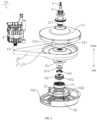
FIG. 1 is a schematic view of a drive system according to an embodiment of the present disclosure; -
FIG. 2 is an exploded view of a drive system according to an embodiment of the present disclosure; -
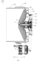
FIG. 3 is a sectional view of a drive system according to an embodiment of the present disclosure; -
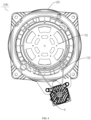
FIG. 4 is a rear view of a drive system according to an embodiment of the present disclosure; -
FIG. 5 is a schematic view of a drum shaft sleeve according to an embodiment of the present disclosure; -
FIG. 6 is a schematic view of a pulsator shaft according to an embodiment of the present disclosure; -
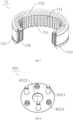
FIG. 7 is a schematic view of a clutch sliding sleeve according to an embodiment of the present disclosure; -
FIG. 8 is a schematic view of a planetary carrier according to an embodiment of the present disclosure; -
FIG. 9 is a schematic view of a cover plate according to an embodiment of the present disclosure; -
FIG. 10 is a schematic view of an inner gear ring according to an embodiment of the present disclosure; and -
FIG. 11 is a schematic view of the assembly relationship of a gear transmission component according to an embodiment of the present disclosure. - Embodiments of the present disclosure will be described in detail below, and the examples of the embodiments will be illustrated in the drawings. The same or similar elements and the elements having same or similar functions are denoted by like reference numerals throughout the description. The embodiments described herein with reference to the drawings are illustrative and used to generally understand the present disclosure. The embodiments shall not be construed to limit the present disclosure.
- A
drive system 10 of awashing machine 100 according to embodiments of the present disclosure will be described below with reference toFIGS. 1 to 11 . - As illustrated in
FIGS. 1 to 4 , for thedrive system 10 of thewashing machine 100 according to embodiments of the present disclosure, thewashing machine 100 includes thedrive system 10, anouter tub 20, adrum 30, and apulsator 40. Thedrum 30 is rotatably arranged within theouter tub 20, and thepulsator 40 is rotatably arranged at a bottom of thedrum 30, wherein the bottom of thedrum 30 is opposite to an opening of thedrum 30. For example, as illustrated inFIG. 3 , thedrum 30 has a washing chamber therein, a front of the washing chamber is formed with an opening, and thepulsator 40 is rotatably arranged at a rear of the washing chamber. - As illustrated in
FIGS. 1 to 4 , thedrive system 10 can include apulsator shaft 1, adrum shaft sleeve 2, abracket component 3, amotor 4, abelt transmission mechanism 5, agear transmission mechanism 6, and aclutch mechanism 7. - Referring to
FIG. 3 , a first end of the pulsator shaft 1 (for example, a front end illustrated inFIG. 3 ) is adapted to be connected to thepulsator 40; thedrum shaft sleeve 2 is fitted over an outer periphery of thepulsator shaft 1; thepulsator shaft 1 is rotatable relative to thedrum shaft sleeve 2 to drive thepulsator 40 to rotate; a first end of the drum shaft sleeve 2 (for example, a rear end illustrated inFIG. 3 ) is adapted to be connected to thedrum 30; and thedrum shaft sleeve 2 can drive thedrum 30 to rotate. - Referring to
FIG. 3 , thedrum shaft sleeve 2 is arranged on thebracket component 3 and is rotatable relative to thebracket component 3; thebracket component 3 is adapted to be connected to theouter tub 20; themotor 4 is an inner rotor motor and is adapted to be connected to theouter tub 20. Therefore, it is advantageous to reducing the cost and energy consumption of themotor 4. For example, themotor 4 is a BLDC inner rotor motor (brushless direct current inner rotor motor). - As illustrated in
FIG. 2 , thebelt transmission mechanism 5 includes abelt pulley 51 and abelt 52. One end of thebelt 52 is fitted over an outer peripheral side of anoutput shaft 41 of themotor 4, while the other end of thebelt 52 is fitted over an outer peripheral side of thebelt pulley 51. Thebelt pulley 51 is connected to a second end of thedrum shaft sleeve 2. A second end of thepulsator shaft 1 is connected to thebelt transmission mechanism 5 through thegear transmission mechanism 6. When the motor is working, thebelt transmission mechanism 5 transmits power of themotor 4 to thedrum shaft sleeve 2 to drive thedrum shaft sleeve 2 to rotate; at the same time, thebelt transmission mechanism 5 transmits the power of themotor 4 to thegear transmission mechanism 6, and in turn to thepulsator shaft 1 through thegear transmission mechanism 6, thereby driving thepulsator shaft 1 to rotate. - It can be appreciated that the
pulsator shaft 1 is a slender shaft, and a diameter of thedrum shaft sleeve 2 is greater than a diameter of thepulsator shaft 1. Compared with the traditional art where a rotor of a motor is directly fixed on a pulsator shaft, by connecting thebelt pulley 51 to the second end of thedrum shaft sleeve 2, the rigidity of thedrive system 10 can be enhanced, and thebelt pulley 51 occupies a smaller space in a length direction of thepulsator shaft 1 than themotor 4, which is advantageous to reducing an axial size of thedrive system 10. In addition, the power of themotor 4 is transmitted to thegear transmission mechanism 6 through thebelt 52 and thebelt pulley 51, which can reduce the rotation speed and increase the torque, thereby ensuring a starting torque of thewashing machine 100. - As illustrated in
FIGS. 1 and2 , theclutch mechanism 7 selectively cooperates with one of thegear transmission mechanism 6 and thebracket component 3. When theclutch mechanism 7 cooperates with thegear transmission mechanism 6, thepulsator shaft 1 and thedrum shaft sleeve 2 rotate synchronously. When theclutch mechanism 7 cooperates with thebracket component 3, thepulsator shaft 1 and thedrum shaft sleeve 2 rotate at different speeds. "The synchronous rotation of thepulsator shaft 1 and thedrum shaft sleeve 2" means that thepulsator shaft 1 and thedrum shaft sleeve 2 rotate in the same direction and at the same angular speed, and "differential rotation of thepulsator shaft 1 and thedrum shaft sleeve 2" means that thepulsator shaft 1 and thedrum shaft sleeve 2 rotate at different angular speeds, wherein the differential rotation can be in the same direction or in the opposite directions. Therefore, thepulsator shaft 1 and drumshaft sleeve 2 can be switched between one washing mode of the synchronous rotation and another washing mode of the differential rotation. In a washing condition, by controlling whether thepulsator shaft 1 and thedrum shaft sleeve 2 rotate at different speeds, it is possible to control whether thedrum 30 and thepulsator 40 rotate at different speeds (i.e., switching between a dual-output washing mode and a single-output washing mode), such that thewashing machine 100 can adapt to clothes of different materials. For example, during washing, thewashing machine 100 can be switched to the single-output washing state (with thepulsator shaft 1 and thedrum shaft sleeve 2 rotating synchronously), and in such a case, thewashing machine 100 has the advantage of not damaging the clothes, and can wash clothes that need gentle washing such as cashmere or silk. When thewashing machine 100 is switched to the dual-output washing state (with thepulsator shaft 1 and thedrum shaft sleeve 2 rotating differentially), thewashing machine 100 has a strong washing capacity, and can wash clothes with stubborn stains or clothes made of washable materials. - For the
drive system 10 of thewashing machine 100 according to the embodiments of the present disclosure, by configuring themotor 4 as the inner rotor motor, and transmitting the power of themotor 4 to theinner gear ring 61 through thebelt 52 and thebelt pulley 51, on the premise of ensuring the starting torque of thewashing machine 100, the cost and energy consumption of themotor 4 can be reduced, which is advantageous to reducing the cost and energy consumption of thedrive system 10. Compared with the traditional art where motors are fixed on motor shafts, thebelt pulley 51 is connected to the second end of thedrum shaft sleeve 2, which is advantageous to improving the rigidity of thedrive system 10, and reducing the axial size of the drive system. In addition, when theclutch mechanism 7 cooperates with thegear transmission mechanism 6, thepulsator shaft 1 and thedrum shaft sleeve 2 rotate synchronously; when theclutch mechanism 7 cooperates with thebracket component 3, thepulsator shaft 1 and thedrum shaft sleeve 2 rotate at different speeds. As a result, thepulsator shaft 1 and thedrum shaft sleeve 2 can be switched between two modes of the synchronous rotation and the differential rotation, to allow thewashing machine 100 to adapt to clothes of different materials. - In some embodiments of the present disclosure, as illustrated in
FIG. 2 , thebelt pulley 51 has acentral hole 511 with afirst spline portion 512 formed on an inner peripheral wall of thecentral hole 511. The second end of thedrum shaft sleeve 2 has a beltpulley connecting portion 21 fitted in thecentral hole 511, and the beltpulley connecting portion 21 is formed with asecond spline portion 211 cooperating with thefirst spline portion 512. Therefore, through the cooperation between thefirst spline portion 512 on the inner peripheral wall of thecentral hole 511 and thesecond spline portion 211 of the beltpulley connecting portion 21, it is advantageous to improving the strength of connection between thebelt pulley 51 and thedrum shaft sleeve 2, thereby enhancing the stability of operation of thebelt pulley 51 driving thedrum shaft sleeve 2. - In some embodiments of the present disclosure, as illustrated in
FIGS. 1 and2 , thebracket component 3 includes a bearingbracket 31 and arear housing 32 connected with each other. The bearingbracket 31 is provided with a bearing thereon, and the bearing is fitted over an outer periphery of thedrum shaft sleeve 2. Therear housing 32 is arranged at an axial side of the bearingbracket 31. An accommodating space is defined between the bearingbracket 31 and therear housing 32, and thebelt transmission mechanism 5, thegear transmission mechanism 6, and theclutch mechanism 7 are located within the accommodating space. Therefore, thebelt transmission mechanism 5, thegear transmission mechanism 6, and theclutch mechanism 7 are isolated from the external environment, which is beneficial to improving the operational stability of thebelt transmission mechanism 5, thegear transmission mechanism 6, and theclutch mechanism 7. - For example, as illustrated in
FIG. 1 , the bearingbracket 31 is fixedly connected to theouter tub 20, and a front end and a rear end of an inner hole of the bearing bracket are provided with afirst bearing chamber 311 and asecond bearing chamber 312, respectively. Outer rings of afirst bearing 86 and asecond bearing 87 are fixedly mounted within thefirst bearing chamber 311 and thesecond bearing chamber 312, respectively. Thedrum shaft sleeve 2 is rotatably mounted in the inner hole of the bearingbracket 31 through thefirst bearing 86 and thesecond bearing 87. The rear end of thedrum shaft sleeve 2 is provided with the beltpulley connecting portion 21. Thebelt pulley 51 with an opening backward is fixedly connected to the beltpulley connecting portion 21. Thedrum shaft sleeve 2 is of a hollow structure. Referring toFIGS. 1 and11 , thepulsator shaft 1 is rotatably arranged in thedrum shaft sleeve 2 through afirst bushing 81 and asecond bushing 82 press-fitted in an inner hole of thedrum shaft sleeve 2. - In some embodiments of the present disclosure, the bearing
bracket 31 is an integrally formed member. Therefore, it is beneficial to improving the supporting rigidity of the bearingbracket 31. - In some embodiments of the present disclosure, as illustrated in
FIG. 6 , thedrum shaft sleeve 2 is a hollow rotating structure; an outer peripheral wall of thedrum shaft sleeve 2 is provided with adrum connecting portion 22, a large oilseal connecting portion 23, abearing mounting portion 24, and a beltpulley connecting portion 21 in sequence from front to rear; and the inner hole of thedrum shaft sleeve 2 is provided with a small oilseal mounting portion 25, a firstbushing mounting portion 26, a secondbushing mounting portion 27, and anavoidance groove 28 in sequence from front to rear. During assembly, referring toFIG. 1 , thedrum shaft sleeve 2 is fitted into a bearing hole from an end of thefirst bearing 86; thebearing mounting portion 24 is mounted in inner holes of thefirst bearing 86 and thesecond bearing 87, so that thedrum shaft sleeve 2 is rotatably mounted within the bearingbracket 31; a front end of thedrum shaft sleeve 2 is fixedly connected to thedrum 30 through thedrum connecting portion 22, and the beltpulley connecting portion 21 located at the rear end of thedrum shaft sleeve 2 is fixedly connected to thebelt pulley 51. - Further, the
pulsator shaft 1 is provided with apulsator connecting portion 11, a small oilseal connecting portion 12, abushing mounting portion 13, afirst shaft shoulder 14, and asecond shaft shoulder 15 in sequence from front to rear. Thepulsator shaft 1 is rotatably supported in the inner hole of thedrum shaft sleeve 2 through thefirst bushing 81 and thesecond bushing 82, and thepulsator shaft 1 is forwardly limited to thesecond bushing 82 by thefirst shaft shoulder 14. A side of thepulsator shaft 1 where thefirst bushing 81 is exposed is equipped with an adjustingwasher 93 for adjusting a axial movement between thepulsator shaft 1 and thedrum shaft sleeve 2. Moreover, thepulsator shaft 1 is backwardly limited to thefirst bushing 81 by anelastic retaining ring 94 arranged at a front end of the adjustingwasher 93. The front end of thepulsator shaft 1 is fixedly connected to thepulsator 40 through thepulsator connecting portion 11, and a rear end of thepulsator shaft 1 is fixedly connected with asun gear 62 and limited to thesecond shaft shoulder 15. Therefore, the operation of thepulsator shaft 1 can be made stable and reliable. - In some embodiments of the present disclosure, seals are provided among the bearing
bracket 31, thedrum shaft sleeve 2, and thepulsator shaft 1, and the seals include alarge water seal 91 and asmall water seal 92. Thelarge water seal 91 is fixedly mounted in an inner hole of a front end of the bearingbracket 31 and is inwardly sealed and connected with thedrum shaft sleeve 2. Thesmall water seal 92 is fixedly mounted in an inner hole of the front end of thedrum shaft sleeve 2 and is inwardly sealed and connected with thepulsator shaft 1. Specifically, as illustrated inFIG. 1 , thelarge water seal 91 is fixed at the front end of the bearingbracket 31, and afirst sealing lip 911 is provided in the inner hole of the bearingbracket 31 and abuts against the large oilseal connecting portion 23 of thedrum shaft sleeve 2; an outer ring of thesmall water seal 92 is fixedly connected to the small oilseal mounting portion 25 of thedrum shaft sleeve 2, and thesmall water seal 92 is inwardly provided with athird sealing lip 921 which abuts against the small oilseal connecting portion 12 of thepulsator shaft 1. - In some optional embodiments of the present disclosure, as illustrated in
FIG. 2 , an outer peripheral wall of therear housing 32 is formed with anavoidance notch 321, and one end of thebelt 52 passes through theavoidance notch 321 and is fitted over the outer peripheral side of theoutput shaft 41. Therefore, by providing theavoidance notch 321, it is convenient for two ends of thebelt 52 to be connected to theoutput shaft 41 and thebelt pulley 51 respectively, and interference between thebelt 52 and therear housing 32 can be avoided. For example, themotor 4 is fixedly connected to theouter tub 20, and a shaft of themotor 4 is parallel to thepulsator shaft 1; one end of thebelt 52 is fitted over the outer peripheral side of theoutput shaft 41 of themotor 4, while the other end of thebelt 52 is fitted over the outer peripheral side of thebelt pulley 51; therear housing 32 with an opening forward is fixedly connected to a rear end face of the bearingbracket 31 and fitted over thebelt 52 without contact; one side of therear housing 32 is provided with theavoidance notch 321 adapted to avoid thebelt 52, and thebelt 52 passes through theavoidance notch 321 and is connected to themotor 4. - In some embodiments of the present disclosure, as illustrated in
FIGS. 2 and11 , thegear transmission mechanism 6 includes: aninner gear ring 61, asun gear 62, aplanetary carrier component 63, and aplanetary gear 64. Theinner gear ring 61 is connected to and arranged coaxially with thebelt pulley 51. When theclutch mechanism 7 cooperates with theinner gear ring 61, thepulsator shaft 1 and thedrum shaft sleeve 2 rotate synchronously. Thesun gear 62 is connected to and arranged coaxially with thepulsator shaft 1, and thesun gear 62 is located at an inner side of theinner gear ring 61. Theplanetary carrier component 63 has a plurality ofplanetary gear shafts 6315, and theplanetary carrier component 63 is fitted over the outer periphery of thepulsator shaft 1 and is rotatable relative to thepulsator shaft 1. A plurality of theplanetary gears 64 are provided and rotatably fitted over the plurality ofplanetary gear shafts 6315 correspondingly. The plurality of theplanetary gears 64 are located between theinner gear ring 61 and thesun gear 62 and arranged around an outer periphery of thesun gear 62. Theplanetary gears 64 mesh with theinner gear ring 61 and thesun gear 62. - It should be noted that when the
clutch mechanism 7 cooperates with theinner gear ring 61, theplanetary carrier component 63 is fixedly connected to theinner gear ring 61, so that theinner gear ring 61, theplanetary carrier component 63, theplanetary gear 64, thesun gear 62, and thepulsator shaft 1 run at the same angular speed. Moreover, since both theinner gear ring 61 and thedrum shaft sleeve 2 are connected to and arranged coaxially with thebelt pulley 51, thepulsator shaft 1 and thedrum shaft sleeve 2 rotate synchronously. When theclutch mechanism 7 cooperates with thebracket component 3, theplanetary carrier component 63 is fixedly connected to thebracket component 3, thebelt transmission mechanism 5 transmits the power of themotor 4 to thedrum shaft sleeve 2 to drive thedrum shaft sleeve 2 to rotate. At the same time, thebelt transmission mechanism 5 transmits the power of themotor 4 to theinner gear ring 61, and in turn theinner gear ring 61 drives theplanetary gear 64 to rotate around theplanetary gear shaft 6315; theplanetary gear 64 drives a central gear to rotate, and the central gear drives thepulsator shaft 1 to rotate; thepulsator shaft 1 and thedrum shaft sleeve 2 rotate at different speeds. Thus, the structure is simple, and it is convenient for thepulsator shaft 1 and thedrum shaft sleeve 2 to realize the synchronous rotation and the differential rotation. - In some embodiments of the present disclosure, as illustrated in
FIG. 2 , the plurality ofplanetary gears 64 form a group, and eachplanetary gear 64 directly meshes with theinner gear ring 61 and thesun gear 62. Therefore, when theclutch mechanism 7 cooperates with thebracket component 3, thepulsator shaft 1 and thedrum shaft sleeve 2 can rotate in reverse directions and at different speeds. - In some optional embodiments of the present disclosure, the plurality of
planetary gears 64 form two groups that mesh with each other. One of the two groups of theplanetary gears 64 meshes with theinner gear ring 61, and the other group meshes with thesun gear 62. Therefore, when theclutch mechanism 7 cooperates with thebracket component 3, thepulsator shaft 1 and thedrum shaft sleeve 2 rotate in the same direction and at different speeds. For example, the plurality ofplanetary gears 64 are divided into a first group of planetary gears and a second group of planetary gears; the first group of planetary gears are arranged adjacent to a center of theinner gear ring 61 and mesh with thesun gear 62; the second group of planetary gears are arranged away from the center of theinner gear ring 61 and mesh with theinner gear ring 61 and the first group of planetary gears. - In some embodiments of the present disclosure, as illustrated in
FIG. 6 , an inner peripheral wall of the second end of thedrum shaft sleeve 2 is formed with theavoidance groove 28 that penetrates an axial end face of the second end of thedrum shaft sleeve 2, a part of theplanetary carrier component 63 is accommodated in theavoidance groove 28, and theplanetary carrier component 63 is spaced from thedrum shaft sleeve 2. Therefore, it is beneficial to reducing the axial size of thedrive system 10. - In some optional embodiments of the present disclosure, as illustrated in
FIG. 1 , theinner gear ring 61 is integrally formed on thebelt pulley 51 by injection molding. Therefore, an integrated injection molding structure can not only ensure the structure and performance stability of theinner gear ring 61 and thebelt pulley 51, but also omit redundant assembly parts and connection processes, the efficiency of assembly between theinner gear ring 61 and thebelt pulley 51 can be improved greatly, and the reliability of connection between theinner gear ring 61 and thebelt pulley 51 can be ensured. - In some embodiments of the present disclosure, as illustrated in
FIGS. 1 ,2 , and7 , theclutch mechanism 7 includes aclutch sliding sleeve 71, anelectromagnetic coil component 72, and acultch spring 73. An inner peripheral wall of theclutch sliding sleeve 71 is formed with athird spline portion 711. Theplanetary carrier component 63 includes aplanetary carrier 631 and acover plate 632 connected to each other. Theinner gear ring 61 is rotatably arranged between an outer peripheral wall of theplanetary carrier 631 and an inner peripheral wall of thecover plate 632. A mounting space is defined between theplanetary carrier 631 and thecover plate 632, and thesun gear 62 and the plurality ofplanetary gears 64 are located in the mounting space. An outer peripheral wall of thecover plate 632 is formed with afourth spline portion 6321 cooperating with thethird spline portion 711. Theclutch sliding sleeve 71 is slidable between a first position and a second position along an axial direction relative to thecover plate 632. Therefore, through the cooperation between thethird spline portion 711 and thefourth spline portion 6321, on the one hand, the movement of theclutch sliding sleeve 71 relative to thecover plate 632 along the axial direction can be guided, and on the other hand, theclutch sliding sleeve 71 cannot rotate relative to thecover plate 632, so that the sliding of theclutch sliding sleeve 71 between the first position and the second position along the axial direction is stable and reliable. For example, theplanetary carrier 631 and thecover plate 632 are fixedly connected by asupport column 6311 and a support column through-hole 6323. - Further, when the
electromagnetic coil component 72 is energized, theelectromagnetic coil component 72 is adapted to drive theclutch sliding sleeve 71 to slide towards a first direction (for example, a front direction as illustrated inFIG. 1 ) along the axial direction, and theclutch spring 73 is used to drive theclutch sliding sleeve 71 to slide towards a second direction (for example, a rear direction as illustrated inFIG. 1 ) opposite to the first direction. When the clutch slidingsleeve 71 slides towards the first direction to the first position, theclutch sliding sleeve 71 cooperates with theinner gear ring 61; when theclutch sliding sleeve 71 slides towards the second direction to the second position (a position of theclutch sliding sleeve 71 as illustrated inFIG. 1 ), theclutch sliding sleeve 71 cooperates with thecarrier assembly 3. Therefore, the sliding of theclutch sliding sleeve 71 can be stable and reliable, and when theclutch sliding sleeve 71 cooperates with theinner gear ring 61, the synchronous rotation of thepulsator shaft 1 and thedrum shaft sleeve 2 can be realized; when theclutch sliding sleeve 71 cooperates with thecarrier assembly 3, the differential rotation of thepulsator shaft 1 and thedrum shaft sleeve 2 can be realized. - In some embodiments of the present disclosure, as illustrated in
FIG. 7 , theclutch sliding sleeve 71 includes a non-magnetically conductive tooth-shapedmember 714 and a magneticallyconductive sleeve 715 cooperating with each other in a radial direction and integrally formed, and the magneticallyconductive sleeve 715 is arranged on an outer ring of the non-magnetically conductive tooth-shapedmember 714. An outer ring of thecover plate 632 is fixedly provided with thefourth spline portion 6321, and theclutch sliding sleeve 71 is axially slidably fitted over an outer side of thefourth spline portion 6321 of thecover plate 632 through thethird spline portion 711 arranged fixedly on the inner hole. Both ends of the non-magnetically conductive tooth-shapedmember 714 are provided with firstclutch teeth 712 and thirdclutch teeth 713. An end face of theinner gear ring 61 facing away from a gear part is integrally provided with anannular flange 612, and one side of theflange 612 facing thegear transmission mechanism 6 is fixedly provided with secondclutch teeth 611 distributed uniformly along a peripheral direction. - In some embodiments of the present disclosure, the second
clutch teeth 611 and theinner gear ring 61 are integrally formed by injection molding, and fourthclutch teeth 322 and therear housing 32 are integrally formed by injection molding. - In some embodiments of the present disclosure, as illustrated in
FIG. 1 , theplanetary carrier 631 and thecover plate 632 have hollow structures, and athird bushing 83 and afourth bushing 84 are fixedly arranged in inner holes of the planetary carrier and the cover plate. The planetary carrier and the cover plate are rotatably fitted over thepulsator shaft 1 without contact, through thethird bushing 83 and thefourth bushing 84. Thesun gear 62 is arranged between thethird bushing 83 and thefourth bushing 84. The thirdbushing mounting portion 6312 integrally arranged with theplanetary carrier 631 is inserted into theavoidance groove 28 of thedrum shaft sleeve 2 and axially limited to thefirst shaft shoulder 14. The double-end support can enhance the connection rigidity of the wholegear transmission mechanism 6, and avoid insufficient rigidity caused by the single-side support, thereby reducing washing noise, and improving the stability of the whole machine. At the same time, the axial size can be reduced by the arrangement of theavoidance groove 28. - In some embodiments of the present disclosure, as illustrated in
FIG. 1 ,2 , and11 , theplanetary carrier component 63 includes theplanetary carrier 631 and thecover plate 632 fixedly connected to each other. The plurality ofplanetary gear shafts 6315 are distributed between theplanetary carrier 631 and thecover plate 632 along the peripheral direction. Theinner gear ring 61 is coaxially fixed to thebelt pulley 51. Thecover plate 632 has a cuplike structure, and theplanetary carrier 632 is located within the cuplike structure. Theinner gear ring 61 is arranged between an outer ring of theplanetary carrier 631 and an inner wall of thecover plate 632, and an inner peripheral wall of theinner gear ring 61 meshes with theplanetary gear 64. - Further, as illustrated in
FIG. 8 and9 , several first mountingholes 6313 and several second mountingholes 6322 are distributed between theplanetary carrier 631 and thecover plate 632 along the peripheral direction respectively, and the first mountingholes 6313 and the second mountingholes 6322 are arranged correspondingly, between which severalplanetary gear shafts 6315 are mounted. Theplanetary gear 64 is fitted over theplanetary gear shaft 6315 without contact and inwardly meshes with thesun gear 62 for transmission. Thecover plate 632 has a cuplike structure, and theplanetary carrier 631 is located within the cuplike structure. Theinner gear ring 61 is coaxially arranged between the outer ring of theplanetary carrier 631 and the inner wall of thecover plate 632, and inner teeth of theinner gear ring 61 mesh with the planetary gear 6412 for transmission. - Further, referring to
FIGS. 8 and11 , the outer ring of theplanetary carrier 631 is integrally provided with afirst oil stopper 6314 projecting outwardly in an annular shape, and an inner ring of theinner gear ring 61 is integrally provided with asecond oil stopper 615 projecting inwardly in an annular shape. When assembly is completed, a gap between thefirst oil stopper 6314 and thesecond oil stopper 615 does not exceed 1 mm. Thesecond oil stopper 615, thefirst oil stopper 6314, thecover plate 632, and a body of theinner gear ring 61 form a labyrinth structure to prevent grease in thegear transmission mechanism 6 from splashing during operation. - In some optional embodiments of the present disclosure, as illustrated in
FIG. 1 , theclutch spring 73 is arranged between thebracket component 3 and theclutch sliding sleeve 71. It should be noted that when thewashing machine 100 is in a non-working state, theclutch sliding sleeve 71 cooperates with theinner gear ring 61, theclutch spring 73 is compressed, and theclutch sliding sleeve 71 is at a dewatering station. During washing, theelectromagnetic coil component 72 is energized, and theclutch sliding sleeve 71 moves towards a direction away from theinner gear ring 61 under an electromagnetic force and compresses theclutch spring 73 is compressed, such that theclutch sliding sleeve 71 cooperates with thebracket component 3, theplanetary carrier component 63 is braked, thegear transmission mechanism 6 becomes a shaft-fixed gear train, and thepulsator shaft 1 and thedrum shaft sleeve 2 rotate at different speeds. During dewatering, theelectromagnetic coil component 72 is de-energized, theclutch sliding sleeve 71 is reset under the action of theclutch spring 73, and theclutch sliding sleeve 71 enters into cooperation with theinner gear ring 61, in which case theplanetary carrier component 63 is fixedly connected with theinner gear ring 61, and the wholegear transmission mechanism 6 operates at the same speed, such that thepulsator shaft 1 and thedrum shaft sleeve 2 rotate synchronously. Therefore, theelectromagnetic coil component 72 is not energized in a dewatering mode, thereby avoiding damage caused by collision between the clutch slidingsleeve 71 and theinner gear ring 61 in case of power down during dewatering. For example, theclutch sliding sleeve 71 is provided with aspring mounting portion 716, and theclutch spring 73 is arranged between thespring mounting portion 716 and therear housing 32. - In some embodiments of the present disclosure, the
clutch spring 73 is arranged between thebelt pulley 51 and theclutch sliding sleeve 71. It should be noted that when thewashing machine 100 is in a non-working state, theclutch sliding sleeve 71 cooperates with thebracket component 3, theclutch spring 73 is compressed, and theclutch sliding sleeve 71 is at a washing station. During dewatering, theelectromagnetic coil component 72 is energized, and theclutch sliding sleeve 71 moves towards a direction away from thebracket component 3 under an electromagnetic force and compresses theclutch spring 73, such that theclutch sliding sleeve 71 cooperates with theinner gear ring 61, in which case theplanetary carrier component 63 is fixedly connected with theinner gear ring 61, and the wholegear transmission mechanism 6 operates at the same speed, such that thepulsator shaft 1 and thedrum shaft sleeve 2 rotate synchronously. During washing, theelectromagnetic coil component 72 is de-energized, theclutch sliding sleeve 71 is reset under the action of theclutch spring 73, and theclutch sliding sleeve 71 enters into cooperation with thebracket component 3; theplanetary carrier component 63 is braked; thegear transmission mechanism 6 becomes a shaft-fixed gear train; and thepulsator shaft 1 and thedrum shaft sleeve 2 rotate at different speeds. Therefore, during washing, theelectromagnetic coil component 72 is not energized, thereby reducing the energy consumption of thewashing machine 100. For example, as illustrated inFIG. 7 , theclutch sliding sleeve 71 is provided with aspring mounting portion 716, and theclutch spring 73 is arranged between thespring mounting portion 716 and thebelt pulley 51. - In some optional embodiments of the present disclosure, as illustrated in
FIG. 7 , a first axial end face of theclutch sliding sleeve 71 is formed with a plurality of firstclutch teeth 712 arranged along the peripheral direction, and theinner gear ring 61 is formed with the secondclutch teeth 611 meshing with the plurality of firstclutch teeth 712; a second axial end face of theclutch sliding sleeve 71 is formed with a plurality of thirdclutch teeth 713 arranged along the peripheral direction, and thebracket component 3 is formed with the fourthclutch teeth 322 meshing with the plurality of thirdclutch teeth 713. Therefore, by meshing between the firstclutch teeth 712 and the secondclutch teeth 611, the reliability of cooperation between the clutch slidingsleeve 71 and theinner gear ring 61 can be improved; and by meshing between the thirdclutch teeth 713 and the fourthclutch teeth 322, the reliability of cooperation between the clutch slidingsleeve 71 and thebracket component 3 can be improved. - In some embodiments of the present disclosure, as illustrated in
FIG. 7 , the firstclutch teeth 712 and the thirdclutch teeth 713 are formed in a step shape in an axial direction of theclutch sliding sleeve 71. Therefore, on the one hand, it is beneficial to increasing a meshing area between the firstclutch teeth 712 and the secondclutch teeth 611, to further improve the reliability of cooperation between the clutch slidingsleeve 71 and theinner gear ring 61; on the other hand, the step-shaped teeth mesh easily, a total height of the teeth is small, and the clutching reliability and the compression of axial height can be controlled effectively. For example, the firstclutch teeth 712 and the thirdclutch teeth 713 each consist of first straight teeth and second straight teeth, the first straight teeth and the second straight teeth are perpendicular to each other, and projections of the firstclutch teeth 712 and the thirdclutch teeth 713 in the axial direction are all step-like. - Further, as illustrated in
FIG. 1 , afifth bushing 85 is mounted in an inner hole of therear housing 32, and theplanetary carrier component 63 is pivotally mounted in an inner hole of thefifth bushing 85 through a fourthbushing mounting portion 6324. Preferably, thefirst bushing 81 to thefifth bushing 85 are all made of oil-retaining bearing materials. - As illustrated in
FIGS. 1 to 11 , adrum washing machine 100 according to embodiments of the present disclosure includes: anouter tub 20, apulsator 40, adrum 30, and theabove drive system 10. The drum is rotatably arranged within theouter tube 20. Thepulsator 40 is rotatably arranged at a bottom of thedrum 30. A first end of thepulsator shaft 1 is connected with thepulsator 40. A first end of thedrum shaft sleeve 2 is connected with thedrum 30. Thebracket component 3 is connected with theouter tub 20. Themotor 4 is connected with theouter tube 20. - For the
drum washing machine 100 according to the embodiments of the present disclosure, by providing theabove drive system 10, and in turn by configuring themotor 4 as the inner rotor motor and transmitting the power of themotor 4 to theinner gear ring 61 by thebelt 52 and thebelt pulley 51, on the premise of ensuring the starting torque of thewashing machine 100, the cost and energy consumption of themotor 4 can be reduced, which is advantageous to reducing the cost and energy consumption of thedrive system 10. Compared with the traditional art where motors are fixed on motor shafts, thebelt pulley 51 is connected to the second end of thedrum shaft sleeve 2, which is advantageous to improving the rigidity of thedrive system 10, and reducing the axial size of the drive system. In addition, when theclutch mechanism 7 cooperates with thegear transmission mechanism 6, thepulsator shaft 1 and thedrum shaft sleeve 2 rotate synchronously; when theclutch mechanism 7 cooperates with thebracket component 3, thepulsator shaft 1 and thedrum shaft sleeve 2 rotate at different speeds. As a result, thepulsator shaft 1 and thedrum shaft sleeve 2 can be switched between two modes of the synchronous rotation and the differential rotation, to allow thewashing machine 100 to adapt to clothes of different materials. - For example, as illustrated in
FIG. 1 , when theclutch mechanism 7 makes theplanetary carrier component 63 and therear housing 32 fixedly connected, themotor 4 transmits the power to theinner gear ring 61 through thebelt pulley 52 in a speed-decreasing and distance-increasing manner, then theinner gear ring 61 transmits the power to thesun gear 62 through the planetary gear in a speed-increasing and distance-decreasing manner, and thesun gear 62 and theinner gear ring 61 drive thepulsator 40 and thedrum 30 to operate at different speeds through thedrum shaft sleeve 2 and thepulsator shaft 1 respectively. When theclutch mechanism 7 makes theinner gear ring 61 and theplanetary carrier component 63 fixedly connected, thewhole gear transmission 6 operates at the same speed, themotor 4 transmits the power to theinner gear ring 61 through themotor 4, and then drives thepulsator 40 and thedrum 30 to operate at the same speed through thegear transmission mechanism 6. - In some embodiments of the present disclosure, the
drum washing machine 100 can switch between a dual-output mode and a single-output mode. It should be noted that by controlling whether thepulsator 40 and thedrum 30 are in a differential speed operation state during washing, the purpose of switching between the single-output washing mode and the dual-output washing mode can be realized, thereby achieving adrum washing machine 100 that can switch between the single-output washing mode and the dual-output washing mode according to washing requirements, and enabling thedrum washing machine 100 to adapt to clothes of different materials. - Specifically, the dual-output mode is as follows: under a washing condition, the
motor 4 runs at a low speed; theclutch mechanism 7 cooperates with thebracket component 3; thebelt pulley 51 drives thedrum 30 to operate at a constant speed ratio and drives thepulsator 40 to operate through thegear transmission mechanism 6; thepulsator shaft 1 and thedrum shaft sleeve 2 rotate at different speeds; a speed ratio of thepulsator 40 to thedrum 30 is a transmission ratio of thegear transmission mechanism 6, in which case thewashing machine 100 is in a dual-output washing state and has a strong cleaning ability to wash stubborn stains or clothes made of washable materials. Under a dewatering condition, themotor 4 runs at a high speed; theclutch mechanism 7 cooperates with thegear transmission mechanism 6; thepulsator shaft 1 and thedrum shaft sleeve 2 rotate synchronously; thepulsator 40 and thedrum 30 are driven by themotor 4 through thebelt pulley 51 to operate at the same high speed. - Specifically, the single-output mode is as follows: under a washing condition, the
motor 4 runs at a low speed; theclutch mechanism 7 cooperates with thegear transmission mechanism 6; thepulsator 40 and thedrum 30 are driven by themotor 4 through thebelt pulley 51 to operate at the same low speed, in which case thewashing machine 100 is in a single-output washing state, has the advantage of not damaging clothes, and can wash clothes that need gentle washing such as cashmere or silk. Under a dewatering condition, themotor 4 runs at a high speed, theclutch mechanism 7 cooperates with thegear transmission mechanism 6; thepulsator shaft 1 and thedrum shaft sleeve 2 rotate synchronously; thepulsator 40 and thedrum 30 are driven by themotor 4 through thebelt pulley 51 to operate at the same high speed. At this time, theclutch mechanism 7 does not switch stations during the conversion between the washing condition and the dewatering condition, which can be realize through an electronic control program.
Claims (15)
- A drive system (10) of a washing machine (100), wherein the washing machine (100) at least comprises the drive system (10), an outer tub (20), a drum (30), and a pulsator (40), the drum (30) being rotatably arranged within the outer tub (20), and the pulsator (40) being rotatably arranged at a bottom of the drum (30),
wherein the drive system (10) comprises:a pulsator shaft (1) having a first end connected to the pulsator (40);a drum shaft sleeve (2) fitted over an outer periphery of the pulsator shaft (1), the pulsator shaft (1) being rotatable relative to the drum shaft sleeve (2), and a first end of the drum shaft sleeve (2) being connected to the drum (30);a bracket component (3), the drum shaft sleeve (2) being arranged on the bracket component (3) and rotatable relative to the bracket component (3), and the bracket component (3) being connected to the outer tub (20);a motor (4);a belt transmission mechanism (5) configured to transmit power of the motor (4) to the drum shaft sleeve (2) and drive the drum shaft sleeve (2) to rotate;a gear transmission mechanism (6), a second end of the pulsator shaft (1) being connected to the belt transmission mechanism (5) through the gear transmission mechanism (6); anda clutch mechanism (7) configured to cooperate with one of the gear transmission mechanism (6) and the bracket component (3), wherein in a configuration where the clutch mechanism (7) cooperates with the gear transmission mechanism (6), the pulsator shaft (1) and the drum shaft sleeve (2) rotate synchronously; characterized in that in a configuration where the clutch mechanism (7) cooperates with the bracket component (3), the pulsator shaft (1) and the drum shaft sleeve (2) rotate at different speeds. - The drive system (10) of the washing machine (100) according to claim 1, wherein the belt transmission mechanism (5) comprises a belt pulley (51) and a belt (52); one end of the belt (52) is fitted over an outer peripheral side of an output shaft (41) of the motor (4), while the other end of the belt is fitted over an outer peripheral side of the belt pulley (51); the belt pulley (51) is connected to a second end of the drum shaft sleeve (2).
- The drive system (10) of the washing machine (100) according to claim 2, wherein the belt pulley (51) has a central hole (511) formed with a first spline portion (512) on an inner peripheral wall of the central hole (511), the second end of the drum shaft sleeve (2) has a belt pulley connecting portion fitted in the central hole (511), and the belt pulley connecting portion (21) is formed with a second spline portion (211) cooperating with the first spline portion (512).
- The drive system (10) of the washing machine (100) according to claim 2, wherein the bracket component (3) comprises a rear housing (32) formed with an avoidance notch (321) on an outer peripheral wall of the rear housing (32), and one end of the belt (52) passes through the avoidance notch (321) and is fitted over the outer peripheral side of the output shaft (41).
- The drive system (10) of the washing machine (100) according to any one of claims 2 to 4, wherein the gear transmission mechanism (6) comprises:an inner gear ring (61) connected to and arranged coaxially with the belt pulley (51), wherein when the clutch mechanism (7) cooperates with the inner gear ring (61), the pulsator shaft (1) and the drum shaft sleeve (2) rotate synchronously;a sun gear (62) connected to and arranged coaxially with the pulsator shaft (1), and located at an inner side of the inner gear ring (61);a planetary carrier component (63) having a plurality of planetary gear shafts (6315), and fitted over the outer periphery of the pulsator shaft (1) and rotatable relative to the pulsator shaft (1); anda plurality of planetary gears (64) rotatably fitted over the plurality of planetary gear shafts (6315) correspondingly, located between the inner gear ring (61) and the sun gear (62), arranged around an outer periphery of the sun gear (62), and meshing with the inner gear ring (61) and the sun gear (62).
- The drive system (10) of the washing machine (100) according to claim 5, wherein the plurality of planetary gears (64) form one group, and each planetary gear (64) directly meshes with the inner gear ring (61) and the sun gear (62).
- The drive system (10) of the washing machine (100) according to claim 5, wherein the plurality of planetary gears (64) form two groups meshing with each other, and one of the two groups of planetary gears (64) meshes with the gear ring while the other group meshes with the sun gear (62).
- The drive system (10) of the washing machine (100) according to claim 5, wherein an inner peripheral wall of the second end of the drum shaft sleeve (2) is formed with an avoidance groove (28) penetrating an axial end face of the second end of the drum shaft sleeve (2), a part of the planetary carrier component (63) is accommodated within the avoidance groove (28), and the planetary carrier component (63) is spaced apart from the drum shaft sleeve (2).
- The drive system (10) of the washing machine (100) according to claim 5, wherein the inner gear ring (61) is integrally formed on the belt pulley (51) by injection molding.
- The drive system (10) of the washing machine (100) according to claim 5, wherein the clutch mechanism (7) comprises:a clutch sliding sleeve (71) formed with a third spline portion (711) on an inner peripheral wall of the clutch sliding sleeve (71), wherein the planetary carrier component (63) comprises a planetary carrier (631) and a cover plate (632) connected with each other; the inner gear ring (61) is rotatably arranged between an outer peripheral wall of the planetary carrier (631) and an inner peripheral wall of the cover plate (632); a mounting space is defined between the planetary carrier (631) and the cover plate (632); the sun gear (62) and the plurality of planetary gears (64) are located within the mounting space; an outer peripheral wall of the cover plate (632) is formed with a fourth spline portion (6321) cooperating with the third spline portion (711); and the clutch sliding sleeve (71) is slidable between a first position and a second position along an axial direction relative to the cover plate (632);an electromagnetic coil component (72) adapted to drive the clutch sliding sleeve (71) to slide towards a first direction along the axial direction when the electromagnetic coil component (72) is energized; anda clutch spring (73) configured to drive the clutch sliding sleeve (71) to slide towards a second direction opposite to the first direction, wherein when the clutch sliding sleeve (71) slides towards the first direction to the first position, the clutch sliding sleeve (71) cooperates with the inner gear ring (61); when the clutch sliding sleeve (71) slides towards the second direction to the second position, the clutch sliding sleeve (71) cooperates with the bracket component (3).
- The drive system (10) of the washing machine (100) according to claim 10, wherein the clutch spring (73) is arranged between the bracket component (3) and the clutch sliding sleeve (71), or the clutch spring (73) is arranged between the belt pulley (51) and the clutch sliding sleeve (71).
- The drive system (10) of the washing machine (100) according to claim 10, wherein a first axial end face of the clutch sliding sleeve (71) is formed with a plurality of first clutch teeth (712) arranged along a peripheral direction; the inner gear ring (61) is formed with a plurality of second clutch teeth (611) meshing with the plurality of first clutch teeth (712); a second axial end face of the clutch sliding sleeve (71) is formed with a plurality of third clutch teeth (713) arranged along the peripheral direction; and the bracket component (3) is formed with a plurality of fourth clutch teeth (322) meshing with the plurality of third clutch teeth (713).
- The drive system (10) of the washing machine (100) according to claim 12, wherein the first clutch teeth (712) and the third clutch teeth (713) are each formed in a step shape in the axial direction of the clutch sliding sleeve (71).
- The drive system (10) of the washing machine (100) according to any one of claims 1 to 13, wherein the bracket component (3) comprises a bearing bracket (31) and a rear housing (32) connected with each other; the bearing bracket (31) is provided with a bearing fitted over an outer periphery of the drum shaft sleeve (2); the rear housing (32) is arranged at an axial side of the bearing bracket (31); an accommodating space is defined between the bearing bracket (31) and the rear housing (32); and the belt transmission mechanism (5), the gear transmission mechanism (6), and the clutch mechanism (7) are located within the accommodating space.
- A drum washing machine (100), comprising:an outer tub (20);a drum (30) rotatably arranged within the outer tub (20);a pulsator (40) rotatably arranged at a bottom of the drum (30); andthe drive system (10) according to any one of claims 1 to 14, wherein the first end of the pulsator shaft (1) is connected to the pulsator (40), the first end of the drum shaft sleeve (2) is connected to the drum (30), and the bracket component (3) is connected to the outer tub (20).
Applications Claiming Priority (3)
| Application Number | Priority Date | Filing Date | Title |
|---|---|---|---|
| CN201810880076.6A CN110804842B (en) | 2018-08-03 | 2018-08-03 | Driving system of washing machine and drum washing machine having the same |
| CN201821254938.6U CN208791999U (en) | 2018-08-03 | 2018-08-03 | The drive system of washing machine and roller washing machine with it |
| PCT/CN2018/120107 WO2020024504A1 (en) | 2018-08-03 | 2018-12-10 | Drive system of washing machine and drum washing machine having same |
Publications (3)
| Publication Number | Publication Date |
|---|---|
| EP3831999A1 EP3831999A1 (en) | 2021-06-09 |
| EP3831999A4 EP3831999A4 (en) | 2021-09-01 |
| EP3831999B1 true EP3831999B1 (en) | 2023-05-24 |
Family
ID=69232283
Family Applications (1)
| Application Number | Title | Priority Date | Filing Date |
|---|---|---|---|
| EP18928409.4A Active EP3831999B1 (en) | 2018-08-03 | 2018-12-10 | Drive system of washing machine and drum washing machine having same |
Country Status (3)
| Country | Link |
|---|---|
| EP (1) | EP3831999B1 (en) |
| KR (1) | KR102481768B1 (en) |
| WO (1) | WO2020024504A1 (en) |
Families Citing this family (3)
| Publication number | Priority date | Publication date | Assignee | Title |
|---|---|---|---|---|
| CN114263010B (en) * | 2020-09-15 | 2024-04-05 | 海信冰箱有限公司 | Drum washing machine |
| CN113794315B (en) * | 2021-09-23 | 2022-11-15 | 深圳市昱森机电有限公司 | Three-phase asynchronous motor |
| CN118385179B (en) * | 2024-06-28 | 2024-09-13 | 江苏雅固标准件有限公司 | Cleaning system for automobile hub machining production |
Family Cites Families (8)
| Publication number | Priority date | Publication date | Assignee | Title |
|---|---|---|---|---|
| JP2685277B2 (en) * | 1989-02-28 | 1997-12-03 | 株式会社東芝 | Clutch device for dehydration washing machine |
| KR100720540B1 (en) * | 2000-12-05 | 2007-05-22 | 엘지전자 주식회사 | Drive of fully automatic washing machine |
| CN101225594B (en) * | 2007-01-15 | 2011-01-12 | 宁国聚隆实业有限公司 | Engaging and disengaging gear for washing machine deceleration clutch and washing machine deceleration clutch thereof |
| CN101255643A (en) * | 2008-03-11 | 2008-09-03 | 无锡小天鹅股份有限公司 | Washing transmission device of washing machine clutch |
| JP6363423B2 (en) * | 2014-08-05 | 2018-07-25 | アクア株式会社 | Drum washing machine |
| CN206127666U (en) * | 2016-10-31 | 2017-04-26 | 宁波普尔机电制造有限公司 | Washer transmission device |
| CN106757995B (en) * | 2016-12-21 | 2023-03-14 | 广东威灵电机制造有限公司 | Driving mechanism for washing machine |
| CN106948129A (en) * | 2017-03-31 | 2017-07-14 | 无锡小天鹅股份有限公司 | The drive assembly of washing machine and the washing machine with it |
-
2018
- 2018-12-10 WO PCT/CN2018/120107 patent/WO2020024504A1/en not_active Ceased
- 2018-12-10 EP EP18928409.4A patent/EP3831999B1/en active Active
- 2018-12-10 KR KR1020217004242A patent/KR102481768B1/en active Active
Also Published As
| Publication number | Publication date |
|---|---|
| EP3831999A1 (en) | 2021-06-09 |
| WO2020024504A1 (en) | 2020-02-06 |
| KR20210029814A (en) | 2021-03-16 |
| KR102481768B1 (en) | 2022-12-26 |
| EP3831999A4 (en) | 2021-09-01 |
Similar Documents
| Publication | Publication Date | Title |
|---|---|---|
| US11970812B2 (en) | Driving system of drum washing machine and drum washing machine | |
| US20040139768A1 (en) | Washing machine | |
| CN108570808B (en) | Drum washing machine and washing control method thereof | |
| KR20000007239A (en) | Device for transferring driving force of washing machine | |
| US20150159312A1 (en) | Washing machine driver | |
| EP3831999A1 (en) | Drive system of washing machine and drum washing machine having same | |
| CN108457047A (en) | The drive system and roller washing machine of roller washing machine | |
| CN108360219A (en) | The drive system and roller washing machine of roller washing machine | |
| KR20170093917A (en) | Washing machine driver | |
| CN110804842B (en) | Driving system of washing machine and drum washing machine having the same | |
| CN211368093U (en) | Clutch for washing machine | |
| CN108611803B (en) | Drum washing machine | |
| KR102065597B1 (en) | Washing machine | |
| CN208183356U (en) | The drive system and roller washing machine of roller washing machine | |
| CN111793935B (en) | Driving clutch device of drum washing machine, drum washing machine and washing control method | |
| CN208201391U (en) | Roller washing machine | |
| CN110835827A (en) | Top-opening type double-power washing machine | |
| CN208183347U (en) | Roller washing machine | |
| KR102919036B1 (en) | Washing machine driving system and a washing machine with the same | |
| KR102045005B1 (en) | Washing machine | |
| CN223017223U (en) | Direct-drive double-power clutch and washing machine | |
| KR102903077B1 (en) | Washing machine driving system and a washing machine with the same | |
| CN112144242B (en) | Washing machine speed reduction clutch and washing machine | |
| CN113152027B (en) | Washing machine speed reduction clutch and washing machine | |
| CN112746459A (en) | Washing machine and control method thereof |
Legal Events
| Date | Code | Title | Description |
|---|---|---|---|
| STAA | Information on the status of an ep patent application or granted ep patent |
Free format text: STATUS: THE INTERNATIONAL PUBLICATION HAS BEEN MADE |
|
| PUAI | Public reference made under article 153(3) epc to a published international application that has entered the european phase |
Free format text: ORIGINAL CODE: 0009012 |
|
| STAA | Information on the status of an ep patent application or granted ep patent |
Free format text: STATUS: REQUEST FOR EXAMINATION WAS MADE |
|
| 17P | Request for examination filed |
Effective date: 20210301 |
|
| AK | Designated contracting states |
Kind code of ref document: A1 Designated state(s): AL AT BE BG CH CY CZ DE DK EE ES FI FR GB GR HR HU IE IS IT LI LT LU LV MC MK MT NL NO PL PT RO RS SE SI SK SM TR |
|
| A4 | Supplementary search report drawn up and despatched |
Effective date: 20210802 |
|
| RIC1 | Information provided on ipc code assigned before grant |
Ipc: D06F 37/30 20200101AFI20210727BHEP Ipc: D06F 37/40 20060101ALI20210727BHEP |
|
| DAV | Request for validation of the european patent (deleted) | ||
| DAX | Request for extension of the european patent (deleted) | ||
| GRAP | Despatch of communication of intention to grant a patent |
Free format text: ORIGINAL CODE: EPIDOSNIGR1 |
|
| STAA | Information on the status of an ep patent application or granted ep patent |
Free format text: STATUS: GRANT OF PATENT IS INTENDED |
|
| INTG | Intention to grant announced |
Effective date: 20230124 |
|
| GRAS | Grant fee paid |
Free format text: ORIGINAL CODE: EPIDOSNIGR3 |
|
| GRAA | (expected) grant |
Free format text: ORIGINAL CODE: 0009210 |
|
| STAA | Information on the status of an ep patent application or granted ep patent |
Free format text: STATUS: THE PATENT HAS BEEN GRANTED |
|
| AK | Designated contracting states |
Kind code of ref document: B1 Designated state(s): AL AT BE BG CH CY CZ DE DK EE ES FI FR GB GR HR HU IE IS IT LI LT LU LV MC MK MT NL NO PL PT RO RS SE SI SK SM TR |
|
| REG | Reference to a national code |
Ref country code: GB Ref legal event code: FG4D |
|
| REG | Reference to a national code |
Ref country code: CH Ref legal event code: EP |
|
| REG | Reference to a national code |
Ref country code: DE Ref legal event code: R096 Ref document number: 602018050345 Country of ref document: DE |
|
| REG | Reference to a national code |
Ref country code: AT Ref legal event code: REF Ref document number: 1569540 Country of ref document: AT Kind code of ref document: T Effective date: 20230615 |
|
| REG | Reference to a national code |
Ref country code: IE Ref legal event code: FG4D |
|
| REG | Reference to a national code |
Ref country code: LT Ref legal event code: MG9D |
|
| REG | Reference to a national code |
Ref country code: NL Ref legal event code: MP Effective date: 20230524 |
|
| PG25 | Lapsed in a contracting state [announced via postgrant information from national office to epo] |
Ref country code: SE Free format text: LAPSE BECAUSE OF FAILURE TO SUBMIT A TRANSLATION OF THE DESCRIPTION OR TO PAY THE FEE WITHIN THE PRESCRIBED TIME-LIMIT Effective date: 20230524 Ref country code: PT Free format text: LAPSE BECAUSE OF FAILURE TO SUBMIT A TRANSLATION OF THE DESCRIPTION OR TO PAY THE FEE WITHIN THE PRESCRIBED TIME-LIMIT Effective date: 20230925 Ref country code: NO Free format text: LAPSE BECAUSE OF FAILURE TO SUBMIT A TRANSLATION OF THE DESCRIPTION OR TO PAY THE FEE WITHIN THE PRESCRIBED TIME-LIMIT Effective date: 20230824 Ref country code: NL Free format text: LAPSE BECAUSE OF FAILURE TO SUBMIT A TRANSLATION OF THE DESCRIPTION OR TO PAY THE FEE WITHIN THE PRESCRIBED TIME-LIMIT Effective date: 20230524 Ref country code: ES Free format text: LAPSE BECAUSE OF FAILURE TO SUBMIT A TRANSLATION OF THE DESCRIPTION OR TO PAY THE FEE WITHIN THE PRESCRIBED TIME-LIMIT Effective date: 20230524 |
|
| PG25 | Lapsed in a contracting state [announced via postgrant information from national office to epo] |
Ref country code: RS Free format text: LAPSE BECAUSE OF FAILURE TO SUBMIT A TRANSLATION OF THE DESCRIPTION OR TO PAY THE FEE WITHIN THE PRESCRIBED TIME-LIMIT Effective date: 20230524 Ref country code: PL Free format text: LAPSE BECAUSE OF FAILURE TO SUBMIT A TRANSLATION OF THE DESCRIPTION OR TO PAY THE FEE WITHIN THE PRESCRIBED TIME-LIMIT Effective date: 20230524 Ref country code: LV Free format text: LAPSE BECAUSE OF FAILURE TO SUBMIT A TRANSLATION OF THE DESCRIPTION OR TO PAY THE FEE WITHIN THE PRESCRIBED TIME-LIMIT Effective date: 20230524 Ref country code: LT Free format text: LAPSE BECAUSE OF FAILURE TO SUBMIT A TRANSLATION OF THE DESCRIPTION OR TO PAY THE FEE WITHIN THE PRESCRIBED TIME-LIMIT Effective date: 20230524 Ref country code: IS Free format text: LAPSE BECAUSE OF FAILURE TO SUBMIT A TRANSLATION OF THE DESCRIPTION OR TO PAY THE FEE WITHIN THE PRESCRIBED TIME-LIMIT Effective date: 20230924 Ref country code: HR Free format text: LAPSE BECAUSE OF FAILURE TO SUBMIT A TRANSLATION OF THE DESCRIPTION OR TO PAY THE FEE WITHIN THE PRESCRIBED TIME-LIMIT Effective date: 20230524 Ref country code: GR Free format text: LAPSE BECAUSE OF FAILURE TO SUBMIT A TRANSLATION OF THE DESCRIPTION OR TO PAY THE FEE WITHIN THE PRESCRIBED TIME-LIMIT Effective date: 20230825 |
|
| PG25 | Lapsed in a contracting state [announced via postgrant information from national office to epo] |
Ref country code: FI Free format text: LAPSE BECAUSE OF FAILURE TO SUBMIT A TRANSLATION OF THE DESCRIPTION OR TO PAY THE FEE WITHIN THE PRESCRIBED TIME-LIMIT Effective date: 20230524 |
|
| PG25 | Lapsed in a contracting state [announced via postgrant information from national office to epo] |
Ref country code: SK Free format text: LAPSE BECAUSE OF FAILURE TO SUBMIT A TRANSLATION OF THE DESCRIPTION OR TO PAY THE FEE WITHIN THE PRESCRIBED TIME-LIMIT Effective date: 20230524 |
|
| PG25 | Lapsed in a contracting state [announced via postgrant information from national office to epo] |
Ref country code: SM Free format text: LAPSE BECAUSE OF FAILURE TO SUBMIT A TRANSLATION OF THE DESCRIPTION OR TO PAY THE FEE WITHIN THE PRESCRIBED TIME-LIMIT Effective date: 20230524 Ref country code: SK Free format text: LAPSE BECAUSE OF FAILURE TO SUBMIT A TRANSLATION OF THE DESCRIPTION OR TO PAY THE FEE WITHIN THE PRESCRIBED TIME-LIMIT Effective date: 20230524 Ref country code: RO Free format text: LAPSE BECAUSE OF FAILURE TO SUBMIT A TRANSLATION OF THE DESCRIPTION OR TO PAY THE FEE WITHIN THE PRESCRIBED TIME-LIMIT Effective date: 20230524 Ref country code: EE Free format text: LAPSE BECAUSE OF FAILURE TO SUBMIT A TRANSLATION OF THE DESCRIPTION OR TO PAY THE FEE WITHIN THE PRESCRIBED TIME-LIMIT Effective date: 20230524 Ref country code: DK Free format text: LAPSE BECAUSE OF FAILURE TO SUBMIT A TRANSLATION OF THE DESCRIPTION OR TO PAY THE FEE WITHIN THE PRESCRIBED TIME-LIMIT Effective date: 20230524 Ref country code: CZ Free format text: LAPSE BECAUSE OF FAILURE TO SUBMIT A TRANSLATION OF THE DESCRIPTION OR TO PAY THE FEE WITHIN THE PRESCRIBED TIME-LIMIT Effective date: 20230524 |
|
| REG | Reference to a national code |
Ref country code: AT Ref legal event code: UEP Ref document number: 1569540 Country of ref document: AT Kind code of ref document: T Effective date: 20230524 |
|
| REG | Reference to a national code |
Ref country code: DE Ref legal event code: R097 Ref document number: 602018050345 Country of ref document: DE |
|
| PLBE | No opposition filed within time limit |
Free format text: ORIGINAL CODE: 0009261 |
|
| STAA | Information on the status of an ep patent application or granted ep patent |
Free format text: STATUS: NO OPPOSITION FILED WITHIN TIME LIMIT |
|
| 26N | No opposition filed |
Effective date: 20240227 |
|
| PG25 | Lapsed in a contracting state [announced via postgrant information from national office to epo] |
Ref country code: SI Free format text: LAPSE BECAUSE OF FAILURE TO SUBMIT A TRANSLATION OF THE DESCRIPTION OR TO PAY THE FEE WITHIN THE PRESCRIBED TIME-LIMIT Effective date: 20230524 |
|
| PG25 | Lapsed in a contracting state [announced via postgrant information from national office to epo] |
Ref country code: SI Free format text: LAPSE BECAUSE OF FAILURE TO SUBMIT A TRANSLATION OF THE DESCRIPTION OR TO PAY THE FEE WITHIN THE PRESCRIBED TIME-LIMIT Effective date: 20230524 |
|
| REG | Reference to a national code |
Ref country code: CH Ref legal event code: PL |
|
| PG25 | Lapsed in a contracting state [announced via postgrant information from national office to epo] |
Ref country code: LU Free format text: LAPSE BECAUSE OF NON-PAYMENT OF DUE FEES Effective date: 20231210 |
|
| PG25 | Lapsed in a contracting state [announced via postgrant information from national office to epo] |
Ref country code: MC Free format text: LAPSE BECAUSE OF FAILURE TO SUBMIT A TRANSLATION OF THE DESCRIPTION OR TO PAY THE FEE WITHIN THE PRESCRIBED TIME-LIMIT Effective date: 20230524 |
|
| GBPC | Gb: european patent ceased through non-payment of renewal fee |
Effective date: 20231210 |
|
| REG | Reference to a national code |
Ref country code: BE Ref legal event code: MM Effective date: 20231231 |
|
| PG25 | Lapsed in a contracting state [announced via postgrant information from national office to epo] |
Ref country code: MC Free format text: LAPSE BECAUSE OF FAILURE TO SUBMIT A TRANSLATION OF THE DESCRIPTION OR TO PAY THE FEE WITHIN THE PRESCRIBED TIME-LIMIT Effective date: 20230524 Ref country code: LU Free format text: LAPSE BECAUSE OF NON-PAYMENT OF DUE FEES Effective date: 20231210 |
|
| REG | Reference to a national code |
Ref country code: IE Ref legal event code: MM4A |
|
| PG25 | Lapsed in a contracting state [announced via postgrant information from national office to epo] |
Ref country code: IE Free format text: LAPSE BECAUSE OF NON-PAYMENT OF DUE FEES Effective date: 20231210 |
|
| PG25 | Lapsed in a contracting state [announced via postgrant information from national office to epo] |
Ref country code: GB Free format text: LAPSE BECAUSE OF NON-PAYMENT OF DUE FEES Effective date: 20231210 |
|
| PG25 | Lapsed in a contracting state [announced via postgrant information from national office to epo] |
Ref country code: BE Free format text: LAPSE BECAUSE OF NON-PAYMENT OF DUE FEES Effective date: 20231231 |
|
| PG25 | Lapsed in a contracting state [announced via postgrant information from national office to epo] |
Ref country code: FR Free format text: LAPSE BECAUSE OF NON-PAYMENT OF DUE FEES Effective date: 20231231 |
|
| PG25 | Lapsed in a contracting state [announced via postgrant information from national office to epo] |
Ref country code: CH Free format text: LAPSE BECAUSE OF NON-PAYMENT OF DUE FEES Effective date: 20231231 |
|
| PG25 | Lapsed in a contracting state [announced via postgrant information from national office to epo] |
Ref country code: IE Free format text: LAPSE BECAUSE OF NON-PAYMENT OF DUE FEES Effective date: 20231210 Ref country code: GB Free format text: LAPSE BECAUSE OF NON-PAYMENT OF DUE FEES Effective date: 20231210 Ref country code: FR Free format text: LAPSE BECAUSE OF NON-PAYMENT OF DUE FEES Effective date: 20231231 Ref country code: CH Free format text: LAPSE BECAUSE OF NON-PAYMENT OF DUE FEES Effective date: 20231231 Ref country code: BE Free format text: LAPSE BECAUSE OF NON-PAYMENT OF DUE FEES Effective date: 20231231 |
|
| PG25 | Lapsed in a contracting state [announced via postgrant information from national office to epo] |
Ref country code: BG Free format text: LAPSE BECAUSE OF FAILURE TO SUBMIT A TRANSLATION OF THE DESCRIPTION OR TO PAY THE FEE WITHIN THE PRESCRIBED TIME-LIMIT Effective date: 20230524 |
|
| PG25 | Lapsed in a contracting state [announced via postgrant information from national office to epo] |
Ref country code: BG Free format text: LAPSE BECAUSE OF FAILURE TO SUBMIT A TRANSLATION OF THE DESCRIPTION OR TO PAY THE FEE WITHIN THE PRESCRIBED TIME-LIMIT Effective date: 20230524 |
|
| REG | Reference to a national code |
Ref country code: DE Ref legal event code: R082 Ref document number: 602018050345 Country of ref document: DE Representative=s name: MAUCHER JENKINS PATENTANWAELTE & RECHTSANWAELT, DE |
|
| PG25 | Lapsed in a contracting state [announced via postgrant information from national office to epo] |
Ref country code: CY Free format text: LAPSE BECAUSE OF FAILURE TO SUBMIT A TRANSLATION OF THE DESCRIPTION OR TO PAY THE FEE WITHIN THE PRESCRIBED TIME-LIMIT; INVALID AB INITIO Effective date: 20181210 |
|
| PG25 | Lapsed in a contracting state [announced via postgrant information from national office to epo] |
Ref country code: HU Free format text: LAPSE BECAUSE OF FAILURE TO SUBMIT A TRANSLATION OF THE DESCRIPTION OR TO PAY THE FEE WITHIN THE PRESCRIBED TIME-LIMIT; INVALID AB INITIO Effective date: 20181210 |
|
| PG25 | Lapsed in a contracting state [announced via postgrant information from national office to epo] |
Ref country code: TR Free format text: LAPSE BECAUSE OF FAILURE TO SUBMIT A TRANSLATION OF THE DESCRIPTION OR TO PAY THE FEE WITHIN THE PRESCRIBED TIME-LIMIT Effective date: 20230524 |
|
| PGFP | Annual fee paid to national office [announced via postgrant information from national office to epo] |
Ref country code: DE Payment date: 20251212 Year of fee payment: 8 |
|
| PGFP | Annual fee paid to national office [announced via postgrant information from national office to epo] |
Ref country code: AT Payment date: 20251212 Year of fee payment: 8 |
|
| PGFP | Annual fee paid to national office [announced via postgrant information from national office to epo] |
Ref country code: IT Payment date: 20251212 Year of fee payment: 8 |