EP3831752A1 - Sheet handling apparatus and sheet handling method - Google Patents
Sheet handling apparatus and sheet handling method Download PDFInfo
- Publication number
- EP3831752A1 EP3831752A1 EP20210918.7A EP20210918A EP3831752A1 EP 3831752 A1 EP3831752 A1 EP 3831752A1 EP 20210918 A EP20210918 A EP 20210918A EP 3831752 A1 EP3831752 A1 EP 3831752A1
- Authority
- EP
- European Patent Office
- Prior art keywords
- storage bag
- sheets
- banknotes
- frame
- handling apparatus
- Prior art date
- Legal status (The legal status is an assumption and is not a legal conclusion. Google has not performed a legal analysis and makes no representation as to the accuracy of the status listed.)
- Granted
Links
Images





Classifications
-
- B—PERFORMING OPERATIONS; TRANSPORTING
- B65—CONVEYING; PACKING; STORING; HANDLING THIN OR FILAMENTARY MATERIAL
- B65H—HANDLING THIN OR FILAMENTARY MATERIAL, e.g. SHEETS, WEBS, CABLES
- B65H29/00—Delivering or advancing articles from machines; Advancing articles to or into piles
- B65H29/38—Delivering or advancing articles from machines; Advancing articles to or into piles by movable piling or advancing arms, frames, plates, or like members with which the articles are maintained in face contact
- B65H29/46—Members reciprocated in rectilinear path
-
- B—PERFORMING OPERATIONS; TRANSPORTING
- B65—CONVEYING; PACKING; STORING; HANDLING THIN OR FILAMENTARY MATERIAL
- B65H—HANDLING THIN OR FILAMENTARY MATERIAL, e.g. SHEETS, WEBS, CABLES
- B65H31/00—Pile receivers
- B65H31/26—Auxiliary devices for retaining articles in the pile
-
- B—PERFORMING OPERATIONS; TRANSPORTING
- B65—CONVEYING; PACKING; STORING; HANDLING THIN OR FILAMENTARY MATERIAL
- B65H—HANDLING THIN OR FILAMENTARY MATERIAL, e.g. SHEETS, WEBS, CABLES
- B65H1/00—Supports or magazines for piles from which articles are to be separated
- B65H1/26—Supports or magazines for piles from which articles are to be separated with auxiliary supports to facilitate introduction or renewal of the pile
- B65H1/266—Support fully or partially removable from the handling machine, e.g. cassette, drawer
-
- B—PERFORMING OPERATIONS; TRANSPORTING
- B65—CONVEYING; PACKING; STORING; HANDLING THIN OR FILAMENTARY MATERIAL
- B65H—HANDLING THIN OR FILAMENTARY MATERIAL, e.g. SHEETS, WEBS, CABLES
- B65H29/00—Delivering or advancing articles from machines; Advancing articles to or into piles
- B65H29/38—Delivering or advancing articles from machines; Advancing articles to or into piles by movable piling or advancing arms, frames, plates, or like members with which the articles are maintained in face contact
-
- B—PERFORMING OPERATIONS; TRANSPORTING
- B65—CONVEYING; PACKING; STORING; HANDLING THIN OR FILAMENTARY MATERIAL
- B65H—HANDLING THIN OR FILAMENTARY MATERIAL, e.g. SHEETS, WEBS, CABLES
- B65H31/00—Pile receivers
- B65H31/04—Pile receivers with movable end support arranged to recede as pile accumulates
- B65H31/08—Pile receivers with movable end support arranged to recede as pile accumulates the articles being piled one above another
- B65H31/10—Pile receivers with movable end support arranged to recede as pile accumulates the articles being piled one above another and applied at the top of the pile
-
- B—PERFORMING OPERATIONS; TRANSPORTING
- B65—CONVEYING; PACKING; STORING; HANDLING THIN OR FILAMENTARY MATERIAL
- B65H—HANDLING THIN OR FILAMENTARY MATERIAL, e.g. SHEETS, WEBS, CABLES
- B65H31/00—Pile receivers
- B65H31/22—Pile receivers removable or interchangeable
-
- B—PERFORMING OPERATIONS; TRANSPORTING
- B65—CONVEYING; PACKING; STORING; HANDLING THIN OR FILAMENTARY MATERIAL
- B65H—HANDLING THIN OR FILAMENTARY MATERIAL, e.g. SHEETS, WEBS, CABLES
- B65H43/00—Use of control, checking, or safety devices, e.g. automatic devices comprising an element for sensing a variable
- B65H43/06—Use of control, checking, or safety devices, e.g. automatic devices comprising an element for sensing a variable detecting, or responding to, completion of pile
-
- B—PERFORMING OPERATIONS; TRANSPORTING
- B65—CONVEYING; PACKING; STORING; HANDLING THIN OR FILAMENTARY MATERIAL
- B65H—HANDLING THIN OR FILAMENTARY MATERIAL, e.g. SHEETS, WEBS, CABLES
- B65H5/00—Feeding articles separated from piles; Feeding articles to machines
- B65H5/26—Duplicate, alternate, selective, or coacting feeds
-
- B—PERFORMING OPERATIONS; TRANSPORTING
- B65—CONVEYING; PACKING; STORING; HANDLING THIN OR FILAMENTARY MATERIAL
- B65H—HANDLING THIN OR FILAMENTARY MATERIAL, e.g. SHEETS, WEBS, CABLES
- B65H2301/00—Handling processes for sheets or webs
- B65H2301/40—Type of handling process
- B65H2301/42—Piling, depiling, handling piles
- B65H2301/422—Handling piles, sets or stacks of articles
- B65H2301/4225—Handling piles, sets or stacks of articles in or on special supports
- B65H2301/42254—Boxes; Cassettes; Containers
- B65H2301/422548—Boxes; Cassettes; Containers filling or loading process
-
- B—PERFORMING OPERATIONS; TRANSPORTING
- B65—CONVEYING; PACKING; STORING; HANDLING THIN OR FILAMENTARY MATERIAL
- B65H—HANDLING THIN OR FILAMENTARY MATERIAL, e.g. SHEETS, WEBS, CABLES
- B65H2404/00—Parts for transporting or guiding the handled material
- B65H2404/60—Other elements in face contact with handled material
- B65H2404/64—Other elements in face contact with handled material reciprocating perpendicularly to face of material, e.g. pushing means
-
- B—PERFORMING OPERATIONS; TRANSPORTING
- B65—CONVEYING; PACKING; STORING; HANDLING THIN OR FILAMENTARY MATERIAL
- B65H—HANDLING THIN OR FILAMENTARY MATERIAL, e.g. SHEETS, WEBS, CABLES
- B65H2701/00—Handled material; Storage means
- B65H2701/10—Handled articles or webs
- B65H2701/19—Specific article or web
- B65H2701/1912—Banknotes, bills and cheques or the like
Definitions
- the present disclosure relates to a sheet handling apparatus and a sheet handling method that handle sheets.
- U.S. Patent No. 9745093 discloses an apparatus for storing sheets in a storage bag.
- a moving member moves sheets stacked in a stacking unit to store these sheets in the storage bag.
- a frame of the storage bag keeps an opening portion of the storage bag open, and the moving member moves into the storage bag through the opening portion while pushing the sheets.
- the moving member moves out of the storage bag through the opening portion after the frame slightly closes the opening portion.
- the moving member has a deformable configuration so as to pass through the narrowed opening portion. After the moving member has moved out of the storage bag, the frame closes the opening portion of the storage bag.
- the moving member for storing sheets into the storage bag needs to have a deformable configuration.
- Such complicated configuration of the member causes increase in size and cost of the sheet handling apparatus.
- the present disclosure is made in view of the problems of the conventional art.
- the present disclosure addresses issues, as described herein, with a sheet handling apparatus and a sheet handling method that can easily store sheets in a storage bag.
- the present disclosure provides a sheet handling apparatus configured to feed sheets from outside into the sheet handling apparatus, transport the fed sheets in a storage area which is outside of a storage bag in the sheet handling apparatus and store the transported sheets in the storage bag through an opening of the storage bag.
- the sheet handling apparatus includes: a holder configured to be capable of detachably holding the storage bag; a pushing member configured to push a plurality of sheets transported in the storage area into the storage bag through the opening of the storage bag; and a pressing member configured to press the sheets stored in the storage bag held by the holder.
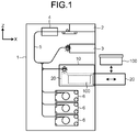
- FIG. 1 is a schematic cross-sectional view showing a configuration of a banknote handling apparatus 1 that is an example of the sheet handling apparatus according to an embodiment of the present disclosure.
- the sheet handling apparatus is configured to handle sheets.
- a banknote is an example of a sheet that can be handled by the sheet handling apparatus.
- the banknote handling apparatus 1 handles banknotes.
- three axes of X, Y, and Z orthogonal to each other are shown so that the relationship between components shown in each drawing can be understood.
- directions in their mounted states are indicated by the three axes.
- the banknote handling apparatus 1 includes a storage mechanism 10.
- the storage mechanism 10 includes a mounting unit 20 that allows a storage bag 100 to be mounted therein and dismounted therefrom.
- the storage bag 100 is used for storing banknotes that are examples of sheets.
- the storage mechanism 10 is disposed inside the housing of the banknote handling apparatus 1.
- the mounting unit 20 can be drawn out from the storage mechanism 10.
- the storage bag 100 can be mounted to and dismounted from the mounting unit 20 drawn from the storage mechanism 10.
- the storage bag 100 is mounted/dismounted from the upper side of the mounting unit 20 as shown by a solid-line arrow in FIG. 1 .
- the direction for mounting and dismounting the storage bag 100 is not limited thereto.
- the storage bag 100 may be mounted to and dismounted from a lateral side of the mounting unit 20. As shown by a broken line in FIG. 1 , the mounting unit 20 to which the storage bag 100 has been mounted can be returned into the storage mechanism 10.
- the banknote handling apparatus 1 may further include a transport unit 5 for transporting banknotes.
- the storage mechanism 10 receives banknotes transported by the transport unit 5 therein and stores the received banknotes into the storage bag 100 mounted in the mounting unit 20.
- the banknote handling apparatus 1 may further include an inlet 2, an outlet 3, a recognition unit 4 and a storage unit 6.
- the banknote handling apparatus 1 can execute dispensing and depositing of banknotes.
- FIG. 1 shows an example of the banknote handling apparatus 1 including a plurality of storage units 6, but the number of storage units are not particularly limited.
- Each storage unit 6 is configured to store banknotes therein.
- Each storage unit 6 may further be configured to feed out the stored banknotes therefrom.
- banknotes which have been selected to be dispensed from among banknotes being stored in the storage units 6, are fed out from the storage units 6.
- the transport unit 5 transports the banknotes from the storage units 6 to the outlet 3.
- the banknotes transported by the transport unit 5 are dispensed to outside of the banknote handling apparatus 1 through the outlet 3.
- banknotes to be deposited are received in the inlet 2.
- the banknotes are fed one by one into the apparatus 1 through the inlet 2.
- the transport unit 5 transports the banknotes fed into the apparatus 1.
- the recognition unit 4 recognizes and counts the banknotes being transported by the transport unit 5.
- the recognition unit 4 recognizes denomination, fitness, and authenticity of each banknote, and counts the number of banknotes for each denomination, the total number of banknotes, and the total amount of the banknotes.
- recognition process of banknotes by the recognition unit 4 may include counting of banknotes. Based on the recognition result of the recognition unit 4, each banknote recognized by the recognition unit 4 is transported to any of the storage units 6, the storage mechanism 10, and the outlet 3.
- a kind of banknote to be stored therein can be set.
- the denomination of banknotes to be stored therein is set.
- a banknote, which is determined not to be deposited as the result of the recognition by the recognition unit 4 is discharged as a reject banknote from the outlet 3.
- a banknote that cannot be recognized by the recognition unit 4 and a banknote that is recognized as a counterfeit note by the recognition unit 4 are discharged from the outlet 3.
- a banknote that can be deposited is stored in a storage unit 6 corresponding to the kind of the banknote, based on the recognition result.
- banknotes are stored in the respective storage units 6 by denomination.
- each storage unit 6 is configured to reel up banknotes together with tapes onto an outer circumferential surface of a drum rotating to store the banknotes, and to feed out the stored banknotes to the transport unit 5 by the drum rotating in a direction opposite to the direction to store banknotes.
- This configuration is an example of the storage unit 6.
- the configuration of the storage unit 6 is not particularly limited as long as the storage unit 6 is configured to store banknotes therein.
- the storage bag 100 mounted to the mounting unit 20 of the storage mechanism 10 stores banknotes therein but does not feed out banknotes. For example, when a storage unit 6 is full and cannot store a banknote therein anymore, this banknote is transported to the storage mechanism 10 and stored in the storage bag 100.
- a banknote which can be deposited but whose denomination is set to none of the storage units 6, is transported to the storage mechanism 10 and stored in the storage bag 100.
- the storage bag 100 is also used for a collection process of collecting banknotes from storage units 6 to the outside of the apparatus 1. Specifically, banknotes to be collected are fed out from the storage units 6, transported to the storage mechanism 10, and stored in the storage bag 100.
- the storage mechanism 10 can close an opening portion of the storage bag 100 having the banknotes stored therein.
- a person in charge of banknote collection draws out the mounting unit 20 from the storage mechanism 10, and takes out the storage bag 100 having the banknotes stored therein, upward from the mounting unit 20 as shown in FIG. 1 .
- the banknotes stored in the storage bag 100 are collected together with the storage bag 100.
- FIG. 2 illustrates a method for mounting and dismounting the storage bag 100 to/from the mounting unit 20 drawn out from the storage mechanism 10.
- FIG. 3 illustrates a method for storing banknotes into the storage bag 100.
- the storage mechanism 10 includes: a detection member 70 that detects an upper end of the banknotes stored in the storage bag 100; a pressing member 80 that presses the banknotes stored in the storage bag 100; and a pushing film 52 that assists pushing of the banknotes by a pushing member 50 (see FIG. 8 ). These components will be described later.
- inner side walls of the storage mechanism 10 are connected to outer side walls of the mounting unit 20 by a plurality of slide rails 22 (22a, 22b).
- These rails 22 constitute a connecting member of the storage mechanism 10 and the mounting unit 20, but this configuration is an example of the connecting member.
- the configuration of the connecting member is not particularly limited as long as the mounting unit 20 is connected to the storage mechanism 10 such that the mounting unit 20 can be drawn out from inside of the storage mechanism 10.
- the rails 22b fixed to the mounting unit 20 slide with respect to the rails 22a fixed to the storage mechanism 10. This allows the mounting unit 20 to move between a position of the unit 20 drawn out from the apparatus 1 as shown in FIG. 2 and a position of the unit 20 in the apparatus 1 to store banknotes in the storage bag 100.
- FIG. 2 shows an example of the mounting unit 20 having a box shape, but the shape of the mounting unit 20 is not particularly limited.
- An upper surface of the mounting unit 20 is open such that the storage bag 100 can be mounted and dismounted from the upper side of the mounting unit 20.
- This is an example of the mounting unit 20, and the configuration of the mounting unit 20 is not particularly limited as long as the storage bag 100 can be mounted to and dismounted from the mounting unit 20.
- the mounting unit 20 may have an opening on a lateral side such that the storage bag 100 is mounted and dismounted from the lateral side of the mounting unit 20.
- a holder mechanism including a pair of holders 30 (30a, 30b) for holding a part of the storage bag 100 near the opening portion of the storage bag 100 is disposed at an upper part of the mounting unit 20.
- the holder 30a and the holder 30b are disposed facing each other.
- the upper surfaces of the holder 30a and the holder 30b may be substantially horizontal.
- the position of the holder 30a is fixed.
- the holder 30b disposed away in the horizontal direction (Y-axis direction) from the holder 30a, is movable in the Y-axis direction.
- a holder driving unit (not shown) drives the holder 30b to move.
- a stage 40 is disposed beneath the holder 30.
- the stage 40 includes a pair of opposing members 40a, 40b disposed facing each other.
- the configuration of the stage 40 is not particularly limited as long as a part of the storage bag 100 mounted to the mounting unit 20 can be placed on the stage 400 and supported by the stage 40.
- the pair of opposing members 40a, 40b are disposed such that a lower part of the storage bag 100 can be inserted between one member 40a and the other member 40b. Consequently, a part of the storage bag 100 is located between one member 40a and the other member 40b.
- the pair of opposing members 40a, 40b are formed of a resin or a metal, but the material is not limited thereto.
- the pair of opposing members 40a, 40b are disposed facing each other, and one member 40a may preferably be disposed away from the other member 40b in the horizontal direction (Y-axis direction).
- the stage 40 may preferably include the support member 40c that supports the pair of opposing members 40a, 40b.
- the opposing members 40a, 40b each have a round-bar shape, but the shape of each member is not thereto.
- the opposing members 40a, 40b may not necessarily have the round-bar shape, and may have any shape as long as parts thereof being in contact with a bag body 102 have curved surfaces so as not to tear the bag body 102.
- at least facing inner-side parts of the opposing members 40a, 40b may be curved in a cross section.
- a gap between the opposing members 40a, 40b is wider at both outer sides than at the center part.
- the pair of opposing members 40a, 40b disposed facing each other have: center parts having a gap of a constant width; and both outer-side parts that have a wider gap than the center parts and are connected to the center parts.
- each of the opposing members 40a, 40b has: the center part parallel to the X-axis; expanding parts that are bent outward, in a horizontal plane (XY plane), at both outer sides with respect to the center part of a predetermined length such that the gap is gradually increased; and both end parts that are bent again in the opposite direction after the gap has been increased to a predetermined width so as to be parallel to the center part.
- the opposing members 40a, 40b are formed such that the length, in the axial direction (X-axis direction), of the center part having the gap of the constant width is equal to or greater than 1/2 of the dimension of the long edge of the banknote supported by the stage 40.
- the width, in the Y-axis direction, of the gap between the center parts of the stage 40 is wider than the thickness of the bag body 102 that is folded such that at least a part of the bag body 102 can be inserted therein.
- the width of the gap between the center parts is adjusted to prevent a plurality of banknotes in a bundle form which are stored in the bag body 102 from falling below the stage 40 through the gap in the bag body 102.
- the stage 40 is movable in the up-down direction (Z-axis direction).
- a spring member (not shown) is attached to the support member 40c of the stage 40.
- the spring member energizes the stage 40 to move upward toward the holder 30.
- the position of the stage 40 can be controlled by a stage driving unit (not shown) that moves the support member 40c in the up-down direction.
- the stage driving unit controls the position of the stage 40 when detection of the upper end of the banknotes in the storage bag 100 is performed and when a frame 101 of the storage bag 100 is closed. The operation of the stage 40 will be described later in detail.
- the storage bag 100 is mounted from the upper opening portion of the mounting unit 20.
- the storage bag 100 includes the frame 101 and the bag body 102.
- the periphery of the opening portion of the bag body 102 is fixed to the side surfaces of the frame 101.
- the entire periphery of the opening portion of the bag body 102 may be fixed to the entire four side surfaces of the frame 101.
- the bag body 102 is adhered to the frame 101 by using an adhesive such that a banknote stored in the bag body 102 does not come out from interspace between the frame 101 and the bag body 102.
- the frame 101 is formed of a hard material while the bag body 102 is formed of a soft material that is foldable, but materials of the frame 101 and bag body 102 are not particularly limited.
- the frame 101 is formed of an opaque hard resin
- the bag body 102 is formed of opaque nylon. Banknotes transported by the transport unit 5 are fed into the storage mechanism 10 and stored inside of the bag body 102 of the storage bag 100.
- the bag body 102 has a plurality of through-holes (not shown) having a diameter of a few millimeters. For example, if someone tries to break the banknote handling apparatus 1 and steal the storage bag 100, the banknote handling apparatus 1 detects this abnormality and sprays antitheft ink toward the storage bag 100. The sprayed ink enters the storage bag 100 through the through-holes and adheres to the banknotes. The adhered ink causes the banknotes to be identified as stolen banknotes.
- the frame 101 has an opening portion 103.
- Banknotes pass through the opening portion 103 of the frame 101 and stored inside of the bag body 102.
- the frame 101 may have a substantially rectangular opening portion 103, which is long in the longitudinal direction (X-axis direction), at substantially the center in the lateral direction (Y-axis direction).
- the frame 101 includes a gate for opening and closing the opening portion 103. Banknotes can pass through the opening portion 103 while the gate is open, but banknotes cannot pass through the opening portion 103 after the gate is closed. The operation of the door will be described later in detail.
- the storage mechanism 10 stacks banknotes 200 on the frame 101 as shown in FIG. 3 .
- a plurality of banknotes 200 are stacked on the frame 101 in the stacking area in the storage mechanism 10.
- the storage mechanism 10 may be provided with a plurality of stacking wheels 60, and a plurality of rollers 61, 62, for example.
- the rollers 61, 62 are disposed facing each other with outer circumferential surfaces thereof being in contact with each other.
- Each stacking wheel 60 has a plurality of blades disposed at equal angular intervals on an outer circumferential surface thereof.
- the storage mechanism 10 may further include a pushing member 50 that pushes the banknotes 200 stacked on the frame 101 of the storage bag 100 into the bag body 102.
- the pushing member 50 is configured to move up-down direction.
- the storage mechanism 10 includes a pantograph arm 51 that supports the pushing member 50 movably in the up-down direction.
- a pushing member driving unit (not shown) drives the arm 51 to expand and contract in the up-down direction
- the pushing member 50 moves in the up-down direction.
- the configuration for moving the pushing member 50 is not limited to the pantograph arm 51 as long as the pushing member 50 can move up-down direction.
- the pushing member 50 moves in the up-down direction between a retracted position shown in FIG. 3 and a pushing position at which the banknotes are pushed into the storage bag 100 (see FIG. 11 ), which will be described later in detail.
- the upper surface of the frame 101 mounted to the holder 30 composes a stacking area for stacking the banknotes 200 fed into the storage mechanism 10.
- This stacking area composes a boundary part of a stacking space in which the banknotes 200 are stacked.
- the banknotes 200 fed into the storage mechanism 10 are stacked in the stacking area, which composes a boundary part of the stacking space, on the upper surface of the frame 101 mounted to the holder 30 in the storage mechanism 10.
- the banknote handling apparatus 1 is configured to stack banknotes 200 transported by the transport unit5 on the frame 101 used as the stacking area of the storage mechanism 10.
- the banknote handling apparatus 1 may drive the rollers 61, 62 and the stacking wheels 60 to rotate, thereby stacking the banknotes 200 on the frame 101.
- a banknote transported by the transport unit 5 passes between the rollers 61, 62 to enter the stacking space, and is sent onto the frame 101 by the stacking wheels 60.
- the storage mechanism 10 uses the rollers 61, 62 and the stacking wheels 60 to stack banknotes 200 in the stacking area on the frame 101, but the configuration of the storage mechanism 10 for stacking banknotes is not limited thereto.
- the frame 101 has a shape that prevents the banknotes 200 from jumping out from the frame 101, i.e., from the stacking area.
- the frame 101 has a projection 101c that projects upward from the upper surface on which the banknotes 200 are stacked.
- the projection 101c is disposed at a position ahead in the moving direction of the banknote fed out by the stacking wheels 60.
- the projection 101c is in contact with at least a part of the side wall of the storage mechanism 10 to fill the gap between the frame 101 and the storage mechanism 10.
- the upper surface of the frame 101 serves as a stacking surface, on which the banknotes 200 are stacked, in the stacking area of the storage mechanism 10.
- the upper surface of the frame 101 mounted to the holder 30 is substantially horizontal.
- the banknotes 200 are stacked on the frame 101 with the faces thereof being parallel to the upper surface of the frame 101.
- the pushing member 50 moves downward and pushes the banknotes 200 into the bag body 102 through the opening portion 103 of the frame 101.
- the banknotes 201 in the bag body 102 are supported by the stage 40 from the lower outside of the bag body 102 such that the banknote faces are substantially horizontal.
- the pushing member 50 pushes the banknotes 200 from the upper side while the stage 40 supports the banknotes 201 from the lower side. This enables the plurality of banknotes 200, 201 to be stored in an aligned and stacked state in the bag body 102 formed of a deformable material.
- the position of the stage 40 energized upward by the spring member changes in the up-down direction according to the number of the banknotes stored in the bag body 102.
- the stage 40 moves downward according to the number of the banknotes 200.
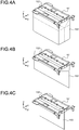
- FIGS. 4A to 4C illustrate a bag portion of the storage bag 100.
- the bag body 102 has a substantially rectangular parallelepiped shape.
- the storage bag 100 can store several hundreds of banknotes, in a stacked state, which are pushed therein by the pushing member 50 through the opening portion 103 of the frame 101. Although the number of storable banknotes varies depending on the degree of damage of the banknotes, the storage bag 100 can store therein 400 to 600 banknotes, for example.
- the bag body 102 before use is folded as shown in FIG. 4B or 4C .
- the bag body 102 is folded at a position indicated by a broken line shown in FIG. 4A .
- the bag body 102 is folded as shown in FIG. 4B .
- the bag body 102 is folded such that the part indicated by the alternate long and short dash line shown in FIG. 4A protrudes inward, the bag body 102 is folded as shown in FIG. 4C .
- the bag body 102 can be inserted easily into the gap between the two opposing members 40a, 40b of the stage 40 shown in FIG. 2 . Even when the length, in the X-axis direction, of the bag body 102 folded as shown in FIG. 4B is longer than the length of the stage 40 in the X-axis direction shown in FIG. 2 , since the gaps between the opposing members 40a, 40b at the both outer sides are wide, both outer parts of the bag body 102 can be easily inserted in these gaps.
- the flat shape of the folded bag body 102 is realized by folding at least a part of the bag body 102, which can form a banknote storage space as shown in FIG. 4A , so as to make a lower part of the bag body 102 flat and reduce the banknote storage space.
- the lower part of the bag body 102 may not necessarily be completely flat as long as the lower part can be inserted in the gap between the two opposing members 40a, 40b of the stage 40.
- a part of the bag body 102 may inflate and/or may form a curved surface.
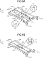
- FIGS. 5A and 5B illustrate the frame 101 of the storage bag 100.
- the opening portion of the bag body 102 is fixed to the side surfaces of the frame 101 by using an adhesive.
- FIG. 5A shows a state where the opening portion 103 of the frame 101 is open
- FIG. 5B shows a state where the opening portion 103 of the frame 101 is closed.
- the opening portion of the storage bag 100 is also open.
- banknotes can be stacked onto the frame 101, and the stacked banknotes can be stored in the bag body 102 by being pushed into the bag body 102 from the opening portion 103 of the frame 101.
- the frame 101 includes a pair of frame members 101a, 101b disposed facing each other.
- the pair of frame members 101a, 101b function as the above-mentioned gate.
- the pair of frame members 101a, 101b forming the gate are separated each other when the opening portion 103 of the frame 101 is open, i.e., the opening portion of the storage bag 100 is open.
- the pair of frame members 101a, 101b forming the gate move and come into contact each other to close the opening portion 103 of the frame 101.
- the opening portion of the storage bag 100 is closed by closing the opening portion 103 of the frame 101.
- the frame 101 may further include connection members 101c connecting longitudinal-side opposed ends of the respective frame members 101a, 101b.
- connection member 101c is bendable in a direction indicated by an arrow in FIG. 5A .
- the connection members 101c bend and substantially center parts thereof move toward the inside of the frame 101 as indicated by arrows in FIG. 5A , whereby the opening portion 103 of the frame 101 can be closed as shown in FIG. 5B .
- the opening portion 103 is formed by a plurality of members 101a, 101b, 101c. As shown in enlarged views in FIG. 5A , on the longitudinal side surface of the frame member 101a facing the frame member 101b, a plurality of hook-shaped connecting portions 111 are disposed. Meanwhile, on the longitudinal side surface of the frame member 101b facing the frame member 101a, a plurality of hook-shaped connecting portions 112 are disposed so as to correspond to the connecting portions 111. A connecting portion 111 and a corresponding connecting portion 112 form a pair, and a plurality of pairs are disposed at unequal intervals in the longitudinal direction.
- the number of connecting portions 111, 112 disposed at both outer sides is larger than the number of the portions 111, 112 at the center in the longitudinal direction so that the connecting portions 111 are not disconnected from the corresponding connecting portions 112 when twisting force is applied to the frame member 101a and the frame member 101b of the gate that has closed the opening portion 103.
- the hook-shaped projection formed at an end of a shaft part of each connecting portion 111 and the hook-shaped projection formed at an end of a shaft part of each connecting portion 112 are engaged with each other as shown in an enlarged view in FIG. 5B when the opening portion 103 is closed by closing the gate.
- the shaft part of the connecting portion 111 is thicker than the shaft part of the connecting portion 112.
- the connecting portion 112 elastically deforms and bows outward while the projection of the connecting portion 112 passes through the position of the projection of the connecting portion 111.
- the connecting portion 112 returns to the original shape after having passed through the position of the projection of the connecting portion 111, whereby the projection of the connecting portion 112 is engaged with the projection of the connecting portion 111.
- the engagement of the connecting portion 111 and the connecting portion 112 causes the frame member 101a and the frame member 101b to be fixed with the opening portion 103 being closed.
- the connecting portions 111, 112 are hidden behind the frame 101 and are not visible from the outside of the storage bag 100.
- the opening portion 103 of the frame 101 cannot be opened. If the once closed opening portion 103 of frame 101 is forcibly opened, the connecting portions 112, which have the thinner shaft parts than the connecting portions 111 and whose projections are engaged with the projections of the connecting portions 111, are broken. The broken connecting portions 112 fall into the bag body 102. After banknotes are stored in the storage bag 100, the opening portion 103 of the frame 101 is closed, and the storage bag 100 with the closed frame 101 is collected from the banknote handling apparatus 1. For example, the collected storage bag 100 is carried to a financial institution.
- the bag body 102 is torn and the banknotes are taken out from the storage bag 100 without opening the opening portion 103 of the frame 101. Therefore, if the opening portion 103 of the frame 101 was opened (or attempted to be opened) after the banknote handling apparatus 1 closed the opening portion 103 of the frame 101, it can be found according to whether or not broken connecting portions 112 are present in the torn bag body 102.
- FIG. 6 illustrates a method for mounting and dismounting the storage bag 100.
- illustration of the bag body 102 is omitted.
- the frame 101 has a plurality of insertion portions 131 (131a, 131b) and 132 (132a, 132b).
- Some insertion portions 131 have a plate spring shape with a projection that allows snap-fit mounting/dismounting.
- An insertion portion 132a insertable in a hole formed substantially in the horizontal direction is disposed at one end of the longitudinal side surface of the frame member 101a of the frame 101, and an insertion portion 131a for snap-fit to be inserted in a hole formed substantially in the vertical direction (Z-axis direction) is disposed at the other end of the frame member 101a.
- an insertion portion 132b insertable in a hole formed substantially in the horizontal direction is disposed at one end of the longitudinal side surface of the frame member 101b, and an insertion portion 131b for snap-fit to be inserted in a hole formed substantially in the vertical direction is disposed at the other end of the frame member 101b.
- holes 32 (32a, 32b) corresponding to the respective insertion portions 132 are formed substantially in the horizontal direction, and holes 31 (31a, 31b) for snap-fit corresponding to the respective insertion portions 131 are formed substantially in the vertical direction.
- Each hole 31 formed in the holder 30 has a dimension that conforms with deformation of the corresponding plate-spring-shaped insertion portion 131.
- a groove for engaging with the projection of the insertion portion 131 is formed inside the hole 31.
- a folded bag body 102 is inserted in the gap between the two opposing members 40a, 40b of the stage 40 (see FIG. 7A ).
- the two insertion portions 132 of the frame 101 are substantially horizontally inserted into the corresponding holes 32 of the holder 30 obliquely from the upper side, and thereafter, the two insertion portions 131 for snap-fit are inserted into the corresponding holes 31 of the holder 30, whereby the storage bag 100 is mounted to the holder 30.
- the frame 101 is fixed to the holder 30 such that the upper surface of the frame member 101a and the upper surface of the frame member 101b are flush with each other to form a substantially horizontal flat surface.
- the frame 101 can be fixed at the predetermined position of the holder 30. Since the insertion portion 132 present at the front side (the X-axis negative direction) of the frame 101 is substantially horizontally inserted in the hole 32 present at the front side of the holder 30 while the insertion portion 131 present at the rear side of the frame 101 is substantially vertically inserted in the hole 31 present at the rear side of the holder 30, a user can easily mount the frame 101 to the holder 30 with one hand.
- the holder 30a and two shafts 33, 34 shown in FIG. 6 are disposed such that the positions thereof are fixed with respect to the mounting unit 20.
- the two shafts 33, 34 are respectively inserted through through-holes formed in the holder 30b.
- the holder 30b is driven by a holder driving unit (not shown) to move in parallel along the shafts 33, 34 as indicated by a solid-line arrow shown in FIG. 6 .
- One holder 30b moves toward the other holder 30a with the frame 101 being mounted thereto.
- the connecting portions 111 of the frame member 101a are connected to the connecting portions 112 of the frame member 101b, whereby the opening portion 103 of the frame 101 can be closed.
- the opening portion of the storage bag 100 is closed by closing the opening portion 103 of the frame 101.
- the storage bag 100 can be removed from the holder 30 through a procedure opposite to the mounting of the frame 101 to the holder 30.
- the two insertion portions 131 are held from outside by one hand to release engagement of snap-fit, and the insertion portions 131 are pulled out upward from the holes 31.
- the insertion portions 132 are pulled out rearward (X-axis positive direction) from the holes 32.
- the frame 101 can be removed from the holder 30.
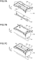
- FIGS. 7A to 7C illustrate stacking and storage of banknotes.
- FIGS. 7A to 7C illustration of some components including the holder 30 is omitted.
- An unused folded bag body 102 is inserted in a gap between the two opposing members 40a, 40b of the stage 40 as shown in FIG. 7A , and the frame 101 is fixed to the holder 30 as described with reference to FIG. 6 .
- FIG. 7B banknotes 200 are stacked on the upper surface of the frame 101 fixed to the holder 30.
- FIG. 7C the banknotes 200 stacked on the frame 101 are pushed by the pushing member 50 into the storage bag 100 through the opening portion 103 of the frame 101 and are stored inside the storage bag 100.
- the opening portion 103 of the frame 101 is formed such that, even when the banknotes 200 are shifted to one side in the short edge direction, one long edge of the banknotes 200 is located on the frame member 101a of the frame 101 while the other long edge of the banknotes 200 is located on the frame member 101b. That is, the opening portion 103 is formed while the position and the size thereof are adjusted such that, both the two long edges of a banknote 200 stacked on the frame 101 are in contact with the upper surface of the frame 101.
- the bag body 102 of the storage bag 100 is folded.
- the pushing member 50 pushes the banknotes 200 on the frame 101 into the bag body 102 through the opening portion 103, folded portions of the bag body 102 are unfolded and the bag body 102 is expanded, whereby a banknote storage space for storing pushed banknotes in the bag body 102 is formed beneath the frame 101 and above the stage 40. Since the gap of the stage 40 is wide at the both outer sides, the folded portions of the bag body 102 can be easily unfolded at these wide gaps.
- the storage mechanism 10 repeats the banknote stacking process shown in FIG. 7B and the banknote pushing process shown in FIG. 7C . According to the number of banknotes stored in the bag body 102, the folded bag body 102 gradually expands downward to increase the banknote storage space formed inside of the bag body 102 for storing banknotes.
- the stage 40 moves downward as the storage space is increased.
- a plurality of detection areas 120 to receive and reflect detection light are provided on the upper surface of the frame 101.
- a detection area 120a is provided on the upper surface of the frame member 101a while a detection area 120b is provided on the upper surface of the frame member 101b.
- the detection areas 120a, 120b are formed by attaching mirror-finished flat members to the frame members 101a, 101b.
- the storage mechanism 10 is provided with sensors (not shown) corresponding to the detection areas 120a, 120b, respectively. Each sensor irradiates the corresponding detection area 120 with detection light emitted from a light emitter, and receives the detection light reflected from the detection area 120 by a light receiver.
- the detection light is reflected from the whole detection area 120.
- the banknotes 200 are stacked on the upper surface of the frame 101 as shown in FIG. 7B , at least a part of the detection area 120 is covered with the banknotes 200, and the intensity of reflected light of the detection light changes.
- the banknote handling apparatus 1 detects presence/absence of banknotes 200 on the frame 101, based on the change in the detection light. For example, if a banknote is left on the frame 101 after the pushing process to store banknotes into the storage bag 100, the banknote handling apparatus 1 detects this banknote by the sensors and executes the pushing process again to store this banknote into the storage bag 100.
- FIG. 8 shows a part of the storage mechanism 10.
- a pushing film 52 may be disposed on a longitudinal side surface of the pushing member 50.
- the pushing film 52 is a member for assisting the pushing process by the pushing member 50, which will be described later in detail.
- the banknote handling apparatus 1 closes the opening portion 103 of the frame 101 of the storage bag 100 by closing the gate of the frame 101 when the number of banknotes stored in the storage bag 100 has reached a predetermined upper limit.
- the opening portion of the storage bag 100 is closed by closing the opening portion 103 of the frame 101.
- the banknote handling apparatus 1 closes the opening portion of the storage bag 100 if an upper end of the stored banknotes has reached a predetermined position in the storage bag 100.
- the storage mechanism 10 includes a detection member 70 for detecting the upper end of banknotes stored in the storage bag 100.
- the detection member 70 is a lever having a thin plate shape.
- the pushing member 50 has a through-hole 50a formed at the position corresponding to the detection member 70.
- the detection member 70 having a thin plate shape is disposed at substantially the center of the through-hole 50a in the lateral direction (Y-axis direction) of the pushing member 50.
- the detection member 70 is retracted inside the through-hole 50a of the pushing member 50.
- the detection member 70 comes out from the through-hole 50a.
- the storage mechanism 10 may further include a pressing member 80 for pressing banknotes stored in the storage bag 100.
- the pressing member 80 is a lever having a thin plate shape, but the shape of the pressing member 80 is not limited thereto.
- the pressing member 80 is disposed outside of the lateral side surface of the pushing member 50, but the position of the pressing member 80 is not limited thereto. While the gate of the frame 101 of the storage bag 100 is moving to close the opening portion 103 of the frame 101, the banknotes being stored in the storage bag 100 are being pressed downward from above by the pressing member so as not to be sandwiched between the two frame members 101a, 101b of the frame 101.
- FIG. 9 illustrates an example of the detection member 70.
- the configuration of the detection member 70 is not particularly limited as long as the detection member 70 can be used for detecting whether or not the upper end of the banknotes being stored in the storage bag 100 has reached the predetermined position.
- the pushing member 50 is shown in its cross section. As shown in FIG. 9 , a shaft 71 having an axis along the Y-axis direction is fixed to the frame 50b of the pushing member 50.
- the detection member 70 is pivotable around the shaft 71 as indicated by an arrow in FIG. 9 .
- FIG. 9 shows a state where the pushing member 50 is present at a detection position between the retracted position where the pushing member 50 is present above the frame 101 of the storage bag 100 and the pushing position where the pushing member 50 is present beneath the frame 101 of the storage bag 100. While the pushing member 50 is at the detection position, the banknote handling apparatus 1 detects whether or not the upper end of the banknotes being stored in the storage bag 100 has reached the predetermined position by using the detection member 70.
- the detection member 70 stops at a predetermined position where a lower surface (detection surface) 70a for detecting a banknote becomes parallel to a lower surface (pushing surface) 50c of the pushing member 50.
- a sensor 72 which emits and receives detection light is disposed such that the detection light passes through a position above the detection member 70 when no banknote is in contact with the detection member 70, as shown by an alternate long and short dash line in FIG. 9 .
- the banknotes push the detection member 70 upward.
- the detection member 70 pivots counterclockwise around the shaft 71 and blocks the detection light of the sensor 72.
- the banknote handling apparatus 1 detects whether or not the upper end of the banknotes stored in the storage bag 100 has reached the predetermined position, based on change between transmission and blocking of the detection light.
- the storage claw 51a formed on the arm 51 comes into contact with a back surface portion 70b of the detection member 70.
- the detection member 70 whose back surface portion 70b is pressed downward by the storage claw 51a, pivots counterclockwise around the shaft 71 and is retracted inside the pushing member 50.
- FIG. 10 illustrates an example of the pressing member 80.
- the configuration of the pressing member 80 is not particularly limited as long as the pressing member 80 can be used for pressing the banknotes being stored in the storage bag 100.IG. 10, the pressing member 80 released from the locking member 83 is indicated by a solid line. A broken line indicates a position of the pressing member 80 locked by the locking member 83.
- a shaft 81 having an axis along the Y-axis direction is fixed to the storage mechanism 10.
- the pressing member 80 is pivotable around the shaft 81 as indicated by an arrow in FIG. 10 .
- the pressing member 80 is energized downward by an energizing member (not shown).
- the energizing member may consist of an elastic member. More preferably, the energizing member may consist of a spring member.
- the pressing member 80 is energized by the spring member in a counterclockwise direction around the shaft 81.
- the pressing member 80 having been released from the locking member 83 is energized by the spring member and pivots in the counterclockwise direction around the shaft 81.
- a part of the pressing member 80 comes into contact with a part of the storage mechanism 10, whereby the pressing member 80 stops at the predetermined position indicated by the solid line in FIG. 10 .
- the pressing member 80 stops at the position where a lower surface (pressing surface) 80a is parallel to the pushing surface 50c of the pushing member 50.
- a storage pin 50e formed on the frame 50b of the pushing member 50 also moves upward. While the storage pin 50e is away from the pressing member 80, the pressing member 80 stops at the position to press banknotes. After the pushing member 50 has moved upward and the storage pin 50e has come into contact with the pressing member 80, the pressing member 80 is pushed upward by the storage pin 50e as the pushing member 50 further moves upward. When the pressing member 80 has been pushed upward to the position indicated by the broken line in FIG. 10 , the locking member 83 locks the pressing member 80.
- the locking member 83 having an L shape is pivotable around a shaft 84 having an axis along the Y-axis direction and fixed to the storage mechanism 10.
- a driving unit (not shown) drives the locking member 83 to pivot around the shaft 84.
- the locking member 83 pivots counterclockwise from the position shown in FIG. 10 , and is engaged with a pin 80b of the pressing member 80 indicated by the broken line, thereby locking the pressing member 80.
- the banknote handling apparatus 1 can repeat the pushing process of pushing banknotes stacked on the frame 101 into the storage bag 100 by moving the pushing member 50 in the up-down direction while the pressing member 80 being locked by the locking member 83.
- the banknote handling apparatus 1 releases the pressing member 80 from the locking member 83.
- the released pressing member 80 energized by the spring member pivots downward to the position indicated by the solid line in FIG. 10 , and presses the banknotes.
- FIGS. 11A to 11D are schematic diagrams illustrating the pushing process.
- FIG. 11A shows a step in which the banknotes 200 transported by the transport unit 5 are stacked onto the frame 101.
- the pushing member 50 is present at the retracted position above the frame 101 so as not to interfere with movement of banknotes to be stacked on the frame 101.
- the banknote handling apparatus 1 stacks the banknotes 200 transported by the transport unit 5, one by one, onto the frame 101 of the storage bag 100 mounted to the holder 30.
- a width d3 of the opening portion 103 shown in FIG. 11A is smaller than the width (short edge dimension) of the banknotes 200 stacked on the upper surface of the frame 101.
- the opening portion 103 is formed such that the left end of the banknotes 200 is away from the left end of the opening portion 103 even when the banknotes 200 are stacked on the rightmost side on the frame 101, and the right end of the banknotes 200 is away from the right end of the opening portion 103 even when the banknotes 200 are stacked on the leftmost side on the frame 101.
- projections 101d are formed so as to project upward from the upper surface of the frame 101 on which the banknotes 200 are stacked.
- the projections 101d are formed along the longitudinal side surface of the frame 101. Since each projection 101d is in contact with at least a part of the side wall of the storage mechanism 10 to fill the gaps between the frame 101 and the storage mechanism 10, the banknotes 200 are prevented from jumping out through the gaps between the storage mechanism 10 and the frame 101.
- the stage 40 is energized upward by the spring member. Therefore, the banknotes 201 stored inside the storage bag 100 are pushed upward by the stage 40 and are pressed against the lower surface of the frame 101 as shown in FIG. 11A . Since the banknotes 201 stored in the storage bag 100 are compressed in the up-down direction while being sandwiched via the storage bag 100 between the upper surface of the stage 40 and the lower surface of the frame 101, the aligned state of the banknotes 201 is maintained.
- a width d1 indicates a width of the pushing surface of the pushing member 50 that contacts with the upper surface of the banknote when the pushing member 50 pushes the banknote in the pushing process.
- the width d1 is smaller than the width d3 of the opening portion 103 (d1 ⁇ d3).
- the pushing member 50 is movable in the up-down direction at a substantially center position in the width direction of the opening portion 103.
- the pushing film 52 may be attached to the lower end of the pushing member 50.
- the pushing film 52 is formed of a thin resin material that is elastically deformable. For example, a polyester film having a thickness of about several hundred ⁇ m is used as the pushing film 52.
- Both outer edges of the pushing film 52 in the width direction (Y-axis direction) are positioned outside of the opening portion 103.
- the pushing member 50 passes through the opening portion 103, the pushing member 50 can pass through the opening portion 103 because the pushing film 52 is elastically deformable.
- a width d2 of the pushing film 52 i.e., a distance d2 between the both outer edges of the pushing film 52, is greater than the width d3 of the opening portion 103 (d2>d3).
- the width d1 is about 15 mm
- the width d2 is about 40 mm
- the width d3 is about 30 mm.
- the banknote handling apparatus 1 suspends stacking of banknotes onto the frame 101, and pushes the stacked banknotes 200 into the storage bag 100 to store the banknotes 200 in the storage bag 100 by the pushing member 50.
- the banknote handling apparatus 1 moves the pushing member 50 downward from the retracted position.
- the pushing member 50 moving downward pushes the banknotes 200 into the opening portion 103 of the opened gate.
- the banknotes are bent while passing the opening portion 103.
- the pushing film 52 passes through the opening portion 103 of the opened gate.
- the pushing file 52 is elastically deformed such that the both outer edges of the pushing film 52 warp upward while passing the opening portion 103.
- the both outer edges of the pushing film 52 come into contact with the inner wall of the opening portion 103 if there is no banknote. That is, the pushing film 52 is formed to fill the gap between the pushing member 50 and the frame 101 when the pushing member 50 passes through the opening portion 103 of the opened gate.
- the pushing member 50 pushes the banknotes 200 through the opening portion 103 of the opened gate as shown in FIG. 11B , the banknotes 200 are reliably pushed into the storage bag 100.
- the pushing member 50 moves to the pushing position a predetermined distance beneath the lower surface of the frame 101.
- the banknotes 200 pushed into the storage bag 100 by the pushing member 50 are pressed against the upper face of the banknotes 201 already stored in the storage bag 100.
- the stage 40 energized by the spring member is also pushed downward from the position where the stage 40 has supported the banknotes 201 shown in FIG.11A and FIG. 11B .
- the pushing member 50 having reached the pushing position moves upward and returns to the retracted position as shown in FIG. 11D .
- the pushing film 52 passes through the opening portion 103 of the opened gate while being elastically deformed such that the both outer edges of the pushing film 52 warp downward.
- the stage 40 energized by the spring member moves upward to press the banknotes 200, 201.
- the upper face of the uppermost banknote among the banknotes 200 newly stored in the storage bag 100 is pressed against the lower surface of the frame 101.
- the banknotes 200, 201 sandwiched between the frame 101 and the stage 40 are compressed in the up-down direction.
- the banknote handling apparatus 1 repeats the stacking process in which a predetermined number of banknotes are stacked on the frame 101 and the pushing process in which the predetermined number of banknotes stacked on the frame 101 are pushed into the storage bag 100. For example, when twenty three banknotes are to be stored in the storage bag 100, the banknote handling apparatus 1 executes, two times, a process of stacking ten banknotes on the frame 101 and pushing these ten banknotes into the storage bag 100, and then performs a process of stacking three banknotes on the frame 101 and pushing these three banknotes into the storage bag 100. Thus, all banknotes are stored in the storage bag 100 by repeating the stacking process and the pushing process three times.
- the banknote handling apparatus 1 executes a sealing process of closing the opening portion 103 as shown in FIG. 5 when a predetermined condition is satisfied.
- the condition for starting the sealing process includes: the number of banknotes stored in the storage bag 100 having reached a predetermined number; the position of the uppermost banknote stored in the storage bag 100 having reached a predetermined position; and the position of the stage 40 having reached a predetermined position.
- the banknote handling apparatus 1 executes the sealing process.
- a user can manually start the sealing process by operating an operation unit of the banknote handling apparatus 1 or an operation terminal device connected to the banknote handling apparatus 1.
- the banknote handling apparatus 1 executes the sealing process.
- the sealing process may be executed automatically or manually, but a trigger to start the sealing process is not particularly limited.
- FIG. 12 is a flowchart illustrating a process of determining whether or not the sealing process is to be executed, and the sealing process.
- the banknote handling apparatus 1 determines whether or not the number of banknotes stored in the storage bag 100 has reached a predetermined number.
- the banknote handling apparatus 1 starts the process shown in FIG. 12 to determine whether or not the sealing process is to be performed.
- the storage bag 100 can store therein 400 to 600 banknotes according to the conditions of the banknotes
- the process shown in FIG. 12 is started. Thereafter, the process shown in FIG. 12 is executed each time the pushing process is executed.
- the banknote handling apparatus 1 which has stored the banknotes into the storage bag 100 through the pushing process, determines whether or not the number of the banknotes stored in the storage bag 100 has reached an upper limit number of banknotes storable in the storage bag 100 (step S1). When the number of the banknotes has reached the upper limit number (step S1: Yes), the banknote handling apparatus 1 determines that no more banknotes can be stored in the storage bag 100, and executes the sealing process (steps S5 to S9).
- step S1 Yes
- the sealing process is executed.
- step S2 determines whether or not the position of the stage 40 has reached a predetermined position.
- the stage 40 which is being energized by the spring member, gradually moves downward according to the number of the banknotes stored in the storage bag 100.
- step S2 determines that the stage 40 has reached the predetermined position.
- step S5 determines that no more banknotes can be stored in the storage bag 100, and executes the sealing process (steps S5 to S9).
- the banknote handling apparatus 1 executes an upper-end detection process (step S3).
- the upper-end detection process it may not necessarily be executed, as shown in FIG. 12 , each time the pushing process is executed after the number of the banknotes in the storage bag 100 has reached the predetermined number (e.g., 150). It can be set that the upper-end detection process is executed once each time the pushing process has been executed a plurality of times. For example, the upper-end detection process may be executed each time 20 banknotes are stored in the storage bag 100.
- the upper-end detection process is executed once each time a process of stacking 10 banknotes on the frame 101 and pushing these 10 banknotes into the storage bag 100 is executed two times.
- FIGS. 13A to 13D are schematic diagrams illustrating the upper-end detection process.
- the pushing member 50 After the pushing process of pushing banknotes into the storage bag 100, the pushing member 50 returns to the retracted position above the frame 101 as shown in FIG. 13A .
- banknotes 202 are pressed against the lower surface of the frame 101 by the stage 40 energized upward by the spring member.
- the pushing member 50 After the pushing process, the pushing member 50 returns to the retracted position shown in FIG. 13A .
- the upper-end detection process is started after the pushing member 50 has returned to the retracted position and it is confirmed that there is no banknotes remaining on the frame 101.
- the pushing member 50 moves downward again.
- the pushing member 50 moves downward from the retracted position shown in FIG. 13 A and pushes the banknotes 202 downward.
- the banknotes 202 are pushed downward to a position where the upper end of the banknotes 202 is separated away from the lower surface of the frame 101 as shown in FIG. 13B .
- the stage driving unit causes the stage 40 to move downward and stop at the predetermined position. As shown in FIG. 13B , the stage 40 stops at the position a distance L1 beneath the lower surface of the frame 101, i.e., the upper surface of the holder 30.
- the pushing member 50 moves upward again from the position where it pushed the banknotes 202 downward as shown in FIG. 13B , and stops at a predetermined detection position as shown in FIG. 13C .
- the detection member 70 is freely pivotable around the shaft 71 as shown in FIG. 9 .
- the detection member 70 does not block the detection light of the sensor 72 shown in FIG. 9 , and therefore, the upper end of the banknotes 202 is not detected.
- the detection member 70 does not block the detection light of the sensor 72 shown in FIG. 9 , and therefore, the upper end of the banknotes 202 is not detected.
- a distance L2 from the lower surface of the frame 101 to the detection surface 70a of the detection member 70 is smaller than a distance L3 from the lower surface of the frame 101 to the upper end of the banknotes 202 (L2 ⁇ L3), the upper end of the banknotes 202 is not detected by the sensor 72.
- step S4 When the upper end of the banknotes is not detected by using the detection member 70 ( FIG. 12 , step S4: No), the banknote handling apparatus 1 ends the process shown in FIG. 12 without executing the sealing process (steps S5 to S9). On the other hand, when the upper end of the banknotes is detected by using the detection member 70 (step S4: Yes), the banknote handling apparatus 1 determines that no more banknotes can be stored in the storage bag 100, and executes the sealing process (steps S5 to S9).
- step S1 when the number of the banknotes in the storage bag 100 has reached the upper limit number (step S1: Yes), when the position of the stage 40 has reached the lower limit position (step S2: Yes), or when the upper end of the banknotes has been detected by using the detection member 70 through the upper-end detection process (step S4: Yes), the banknote handling apparatus 1 automatically executes the sealing process (steps S5 to S9).
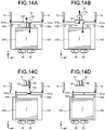
- FIGS. 14A to 14D are schematic diagrams illustrating the sealing process.
- the sealing process is a process of closing the opening portion of the storage bag 100, i.e., the opening portion 103 of the frame 101.
- the pushing member 50 After the pushing process or the upper-end detection process, the pushing member 50 returns to the retracted position.
- the sealing process is started after the pushing member 50 has returned to the retracted position and it is confirmed that there is no banknotes remaining on the frame 101.
- the banknote handling apparatus 1 moves the pushing member 50 downward to the pushing position as shown in FIG. 14A , and then releases the pressing member 80 from the locking member 83 as indicated by the solid line in FIG. 10 . As shown in FIG.
- the pressing member 80 energized by the spring member moves downward, and presses banknotes 204 in the storage bag 100 ( FIG. 12 , step S5). Then, the banknote handling apparatus 1 moves the pushing member 50 upward while the pressing member 80 continues to press the banknotes 204.
- the pushing member 50 retracts to the outside of the storage bag 100, i.e., retracts upward away from the upper surface of the frame 101, while the pressing member 80 holds the banknotes 204 ( FIG. 12 , step S6).
- the holder 30b holding one frame member 101b of the frame 101 starts to move toward the holder 30a holding the other frame member 101a of the frame 101 (step S7).
- the pressing member 80 is lifted upward by the pushing member 50 that is further moving upward from the position shown in FIG. 14B .
- the pressing member 80 retracts to the outside of the storage bag 100, i.e., retracts upward away from the upper surface of the frame 101 ( FIG. 12 , step S8).
- the pressing member 80 is lifted upward by the storage pin 50e of the pushing member 50 that continue to move upward, and then the pressing member 80 is locked by the locking member 83.
- the holder 30b holding the frame member 101b of the frame 101 continues to move toward the holder 30a holding the frame member 101a of the frame 101 while the pushing member 50 and the pressing member 80 are moving upward. Then, the connecting portions 111 of the frame member 101a are engaged with the connecting portions 112 of the frame member 101b as shown in FIG. 5B , whereby the opening portion 103 of the frame 101 is closed and fixed as shown in FIG. 14D ( FIG. 12 , step S9). The opening portion of the storage bag 100 is closed by closing the opening portion 103 of the frame 101.
- the mounting unit 20 is drawn out from the banknote handling apparatus 1, and the storage bag 100 having the banknotes stored therein is dismounted from the mounting unit 20 and collected from the banknote handling apparatus 1.
- the stage 40 includes the two opposing members 40a, 40b that are bent such that the gaps between the opposed end parts are wider than the gap between the center parts.
- the configuration of the stage 40 is not limited thereto.
- the opposing members 40a, 40b shown in FIG. 6 may be composed of only the center parts having the narrow gap therebetween, and supported by the support member 40c.
- the stage 40 is not limited to the configuration in which the opposing members 40a, 40b are supported by the support member 40c.
- the stage 40 may be a plate-like body of which a part is cut out in the same shape as the gap between the opposing members 40a, 40b shown in FIG. 6 .
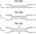
- FIGS. 15A to 15C show other examples of the stage 40.
- Other members having shapes different from the opposing members 40a, 40b can be used for the stage 40 as long as the gaps at the both outer sides are wider than the gap at the center part.
- one member 40a may have a bent shape while the other member 41 may have a linear shape.
- the gaps between the both outer sides may not necessarily be gradually increased.
- two opposing members 42a, 42b each being bent to form a rectangular U shape may be disposed facing each other such that the gaps at the both outer sides are wider than the gap at the center part.
- one of the members 42a, 42b may have a linear shape as in the example of FIG. 15A .
- FIG. 15A shows that the gaps at the both outer sides are wider than the gap at the center part.
- the opposing members 40a, 40b may be inserted in hollow pipes 43a, 43b each having a circular sectional circumference such that the hollow pipes 43a, 43b are rotatable at the center part having the narrow gap.
- the rotatable hollow pipes 43a, 43b at the center part having the narrow gap enable the stage 40 to easily move upward and downward while the lower part of the bag body 102 is being inserted in the gap.
- one of the members 40a, 40b may have a linear shape.
- the opening portion 103 of the frame 101 is closed by using the hook-shaped connecting portions 111, 112 formed at the opposed side surfaces of the frame members 101a, 101b of the frame 101.
- the configuration for closing the frame 101 is not limited thereto.
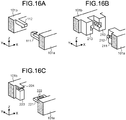
- FIGS. 16A to 16C show other examples of the connecting portions for closing the frame 101.
- the projections of the connecting portions 111, 112 are formed in the longitudinal direction of the frame 101 (X-axis direction).
- the direction of the projections is not limited.
- projections may be formed in the up-down direction.
- connection portion 16A may be wider than the width of the connecting portion 111.
- the increased width of the connection portion 112 facilitates connection with the connecting portion 111.
- the connecting portion 111 may not necessarily elastically deform to be engaged with the connecting portion 112, as long as at least one of the connecting portion 111 and the connecting portion 112 elastically deform.
- the connecting portion 111 may not necessarily be broken when the frame 101 once closed is forcibly opened, as long as at least one of the connecting portion 111 and the connecting portion 112 is broken.
- projections 212 may be formed at both side surfaces of a connecting portion 211 of the frame member 101a while connecting portions 213 having sawtooth-shaped grooves to engage with the projections 212 may be formed on the other frame member 101b. Since the projections 212 of the connecting portion 211 can be inserted into the grooves of the connecting portion 213 but cannot be pulled out from the grooves, the frame 101 can be closed by connecting the connecting portions 211 and the connecting portions 213 with each other. The shape of the axial part of the projection 212 is adjusted according to the material thereof such that the projection 212 is broken when the frame 101 once closed is forcibly opened.
- a connecting portion 221 having a hole 222 may be formed on the frame member 101a while a connecting portion 223 having a hook 224 corresponding to the hole 222 may be formed on the other frame member 101b. Since the hook 224 of the connecting portion 223 of the frame member 101b can be engaged with the hole 222 of the connecting portion 221 of the frame member 101a but cannot be removed from the hole 222, the frame 101 can be closed by connecting the connecting portions 221 and the connecting portions 223 with each other. The shape of the root portion of the hook 224 is adjusted according to the material thereof such that the hook 224 is broken when the frame 101 once closed is forcibly opened.
- the pressing member 80 is energized by the spring member.
- the method for driving the pressing member 80 is not particularly limited as long as the pressing member 80 can be energized to press the banknotes.
- a driving unit using a motor or a solenoid may be used to drive and energize the pressing member 80.
- banknotes are stored in the storage bag 100.
- an object to be stored in the storage bag 100 is not limited to banknotes.
- the storage bag 100 may store therein sheets such as checks, coupons, and securities.
- the sheets can be stored in the storage bag 100 as described above.
- the storage bag 100 may store coins therein.
- coins can be stored in the storage bag 100 as described above.
- a sheet handling apparatus is configured to feed sheets from outside into the sheet handling apparatus, transport the fed sheets in a storage area which is outside of a storage bag in the sheet handling apparatus and store the transported sheets in the storage bag through an opening of the storage bag.
- the sheet handling apparatus includes: a holder configured to be capable of detachably holding the storage bag; a pushing member configured to push a plurality of sheets transported in the storage area into the storage bag through the opening; and a pressing member configured to press the sheets stored in the storage bag held by the holder.
- an area of the pushing member that comes into contact with the sheets when the pushing member pushes the sheets is greater than an area of the pressing member that comes into contact with the sheets when the pressing member presses then sheets.
- the pushing member has a width wider than that of the pressing member in a direction along which the opening of the storage bag is closed after storing the sheets in the storage bag.
- the pressing member presses the sheets while the pushing member is in contact with the sheets to be pushed into the storage bag.
- the pressing member continues to press the sheet even after the pushing member has moved away from the sheets pushed into the storage bag.
- a driver that drives the pushing member and another driver that drives the pressing member are provided independently from each other.
- the sheet handling apparatus further includes: an energizing member configured to energize the pressing member in a direction along which the pressing member presses the sheets stored in the storage bag; and a locking member configured to lock the pressing member that has moved against energizing force by the energizing member and reached at a locking position present outside of the storage bag.
- an energizing member configured to energize the pressing member in a direction along which the pressing member presses the sheets stored in the storage bag
- a locking member configured to lock the pressing member that has moved against energizing force by the energizing member and reached at a locking position present outside of the storage bag.
- the pushing member after the pushing member has moved outside of the storage bag while the pressing member presses the sheets stored in the storage bag, the pushing member, which further moves in a direction away from the storage bag, moves the pressing member to the locking position. Then, the locking member locks the pressing member that has returned to the locking position.
- the sheet handling apparatus further includes a detection member configured to detect that the sheets stored in the storage bag have reached a predetermined position.
- the pressing member presses the sheets when a predetermined number of sheets have been stored in the storage unit or when the detection member has detected the sheets having reached the predetermined position.
- a sheet handling method of storing sheets, which have been fed from outside into a sheet handling apparatus and transported in a storage area which is outside of a storage bag in the sheet handling apparatus, into the storage bag by the sheet handling apparatus includes: pushing, by a pushing member, a plurality of sheets transported in the storage area into the storage bag through an opening of the storage bag held by a holder; pressing, by a pressing member, the sheets stored in the storage bag; moving the pushing member outside of the storage bag while the pressing member presses the sheets; moving the pressing member outside of the storage bag after the holder has started to move to close the opening of the storage bag; and closing, by the holder, the opening of the storage bag after the pressing member has moved outside of the storage bag.
- the sheet handling apparatus includes, in addition to the pushing member that pushes a plurality of sheets stacked outside of the storage bag into the storage bag, the pressing member that presses the sheets stored in the storage bag.
- the sheets pushed into the storage bag by the pushing member can be further pressed by the pressing member.
- the sheets can be easily stored in the storage bag.
- the sheet handling apparatus uses the pushing member whose width is larger than that of the pressing member.
- the sheet handling apparatus moves the pushing member out of the storage bag and presses the sheets in the storage bag by using the pressing member whose width is narrower than that of the pushing member.
- the sheet handling apparatus moves the pressing member out of the storage bag and then closes the opening portion.
- the sheet handling apparatus can easily and reliably perform the operation of storing sheets into the storage bag and closing the opening portion of the storage bag after the storage.
- the sheet handling apparatus and the sheet handling method according to the present embodiment is useful for easily and reliably storing sheets into a storage bag.
Landscapes
- Engineering & Computer Science (AREA)
- Mechanical Engineering (AREA)
- Pile Receivers (AREA)
Abstract
Description
- The present application is based on and claims priority to Japanese Patent Application No.
2019-221640 filed on December 6, 2019 - The present disclosure relates to a sheet handling apparatus and a sheet handling method that handle sheets.
- Conventionally, sheet handling apparatuses for handling sheets have been used. For example,
U.S. Patent No. 9745093 - In the conventional art described above, the moving member for storing sheets into the storage bag needs to have a deformable configuration. Such complicated configuration of the member causes increase in size and cost of the sheet handling apparatus.
- The present disclosure is made in view of the problems of the conventional art. The present disclosure addresses issues, as described herein, with a sheet handling apparatus and a sheet handling method that can easily store sheets in a storage bag.
- The present disclosure provides a sheet handling apparatus configured to feed sheets from outside into the sheet handling apparatus, transport the fed sheets in a storage area which is outside of a storage bag in the sheet handling apparatus and store the transported sheets in the storage bag through an opening of the storage bag. The sheet handling apparatus includes: a holder configured to be capable of detachably holding the storage bag; a pushing member configured to push a plurality of sheets transported in the storage area into the storage bag through the opening of the storage bag; and a pressing member configured to press the sheets stored in the storage bag held by the holder.
-
-
FIG. 1 is a schematic cross-sectional view showing a configuration of a banknote handling apparatus according to an embodiment of the present disclosure; -
FIG. 2 illustrates a method for mounting and dismounting a storage bag to/from a mounting unit drawn out from a storage mechanism; -
FIG. 3 illustrates a method for storing banknotes in the storage bag; -
FIGS. 4A to 4C each illustrate a bag portion of the storage bag; -
FIGS. 5A and 5B each illustrate a frame of the storage bag; -
FIG. 6 illustrates a method for mounting and dismounting the storage bag to a holder; -
FIGS. 7A to 7C illustrate stacking and storage of banknotes; -
FIG. 8 illustrates a part of the storage mechanism; -
FIG. 9 illustrates a detection member; -
FIG. 10 illustrates a pressing member; -
FIGS. 11A to 11D are schematic diagrams illustrating a pushing process; -
FIG. 12 is a flowchart for explaining a sealing process; -
FIGS. 13A to 13D are schematic diagrams illustrating an upper-end detection process; -
FIGS. 14A to 14D are schematic diagrams illustrating a sealing process; -
FIGS. 15A to 15C show other examples of a stage; and -
FIGS. 16A to 16C show other examples of connecting portions for closing the frame. - Hereinafter, a sheet handling apparatus and a sheet handling method according to the present disclosure will be described with reference to the drawings.
FIG. 1 is a schematic cross-sectional view showing a configuration of abanknote handling apparatus 1 that is an example of the sheet handling apparatus according to an embodiment of the present disclosure. The sheet handling apparatus is configured to handle sheets. A banknote is an example of a sheet that can be handled by the sheet handling apparatus. Thebanknote handling apparatus 1 handles banknotes. In the drawings showing the apparatus configuration of the present embodiment, three axes of X, Y, and Z orthogonal to each other are shown so that the relationship between components shown in each drawing can be understood. As for components to be mounted/dismounted, directions in their mounted states are indicated by the three axes. - As shown in
FIG. 1 , thebanknote handling apparatus 1 includes astorage mechanism 10. Thestorage mechanism 10 includes amounting unit 20 that allows astorage bag 100 to be mounted therein and dismounted therefrom. Thestorage bag 100 is used for storing banknotes that are examples of sheets. Thestorage mechanism 10 is disposed inside the housing of thebanknote handling apparatus 1. Themounting unit 20 can be drawn out from thestorage mechanism 10. Thestorage bag 100 can be mounted to and dismounted from themounting unit 20 drawn from thestorage mechanism 10. For example, thestorage bag 100 is mounted/dismounted from the upper side of themounting unit 20 as shown by a solid-line arrow inFIG. 1 . The direction for mounting and dismounting thestorage bag 100 is not limited thereto. Thestorage bag 100 may be mounted to and dismounted from a lateral side of themounting unit 20. As shown by a broken line inFIG. 1 , themounting unit 20 to which thestorage bag 100 has been mounted can be returned into thestorage mechanism 10. Preferably, thebanknote handling apparatus 1 may further include atransport unit 5 for transporting banknotes. Thestorage mechanism 10 receives banknotes transported by thetransport unit 5 therein and stores the received banknotes into thestorage bag 100 mounted in themounting unit 20. - Preferably, the
banknote handling apparatus 1 may further include aninlet 2, anoutlet 3, arecognition unit 4 and astorage unit 6. Thebanknote handling apparatus 1 can execute dispensing and depositing of banknotes.FIG. 1 shows an example of thebanknote handling apparatus 1 including a plurality ofstorage units 6, but the number of storage units are not particularly limited. Eachstorage unit 6 is configured to store banknotes therein. Eachstorage unit 6 may further be configured to feed out the stored banknotes therefrom. In dispensing, banknotes, which have been selected to be dispensed from among banknotes being stored in thestorage units 6, are fed out from thestorage units 6. Thetransport unit 5 transports the banknotes from thestorage units 6 to theoutlet 3. The banknotes transported by thetransport unit 5 are dispensed to outside of thebanknote handling apparatus 1 through theoutlet 3. - In depositing, banknotes to be deposited are received in the
inlet 2. The banknotes are fed one by one into theapparatus 1 through theinlet 2. Thetransport unit 5 transports the banknotes fed into theapparatus 1. Therecognition unit 4 recognizes and counts the banknotes being transported by thetransport unit 5. For example, therecognition unit 4 recognizes denomination, fitness, and authenticity of each banknote, and counts the number of banknotes for each denomination, the total number of banknotes, and the total amount of the banknotes. Hereinafter, recognition process of banknotes by therecognition unit 4 may include counting of banknotes. Based on the recognition result of therecognition unit 4, each banknote recognized by therecognition unit 4 is transported to any of thestorage units 6, thestorage mechanism 10, and theoutlet 3. To each of thestorage units 6, a kind of banknote to be stored therein can be set. For example, to eachstorage unit 6, the denomination of banknotes to be stored therein is set. A banknote, which is determined not to be deposited as the result of the recognition by therecognition unit 4, is discharged as a reject banknote from theoutlet 3. For example, a banknote that cannot be recognized by therecognition unit 4 and a banknote that is recognized as a counterfeit note by therecognition unit 4 are discharged from theoutlet 3. Meanwhile, a banknote that can be deposited is stored in astorage unit 6 corresponding to the kind of the banknote, based on the recognition result. For example, banknotes are stored in therespective storage units 6 by denomination. - For example, each
storage unit 6 is configured to reel up banknotes together with tapes onto an outer circumferential surface of a drum rotating to store the banknotes, and to feed out the stored banknotes to thetransport unit 5 by the drum rotating in a direction opposite to the direction to store banknotes. This configuration is an example of thestorage unit 6. The configuration of thestorage unit 6 is not particularly limited as long as thestorage unit 6 is configured to store banknotes therein. Thestorage bag 100 mounted to the mountingunit 20 of thestorage mechanism 10 stores banknotes therein but does not feed out banknotes. For example, when astorage unit 6 is full and cannot store a banknote therein anymore, this banknote is transported to thestorage mechanism 10 and stored in thestorage bag 100. For another example, a banknote, which can be deposited but whose denomination is set to none of thestorage units 6, is transported to thestorage mechanism 10 and stored in thestorage bag 100. Thestorage bag 100 is also used for a collection process of collecting banknotes fromstorage units 6 to the outside of theapparatus 1. Specifically, banknotes to be collected are fed out from thestorage units 6, transported to thestorage mechanism 10, and stored in thestorage bag 100. Thestorage mechanism 10 can close an opening portion of thestorage bag 100 having the banknotes stored therein. A person in charge of banknote collection draws out the mountingunit 20 from thestorage mechanism 10, and takes out thestorage bag 100 having the banknotes stored therein, upward from the mountingunit 20 as shown inFIG. 1 . The banknotes stored in thestorage bag 100 are collected together with thestorage bag 100. -
FIG. 2 illustrates a method for mounting and dismounting thestorage bag 100 to/from the mountingunit 20 drawn out from thestorage mechanism 10.FIG. 3 illustrates a method for storing banknotes into thestorage bag 100. Although not shown inFIG. 2 andFIG. 3 , thestorage mechanism 10 includes: adetection member 70 that detects an upper end of the banknotes stored in thestorage bag 100; a pressingmember 80 that presses the banknotes stored in thestorage bag 100; and a pushingfilm 52 that assists pushing of the banknotes by a pushing member 50 (seeFIG. 8 ). These components will be described later. - As shown in
FIG. 2 , inner side walls of thestorage mechanism 10 are connected to outer side walls of the mountingunit 20 by a plurality of slide rails 22 (22a, 22b). These rails 22 constitute a connecting member of thestorage mechanism 10 and the mountingunit 20, but this configuration is an example of the connecting member. The configuration of the connecting member is not particularly limited as long as the mountingunit 20 is connected to thestorage mechanism 10 such that the mountingunit 20 can be drawn out from inside of thestorage mechanism 10. Therails 22b fixed to the mountingunit 20 slide with respect to therails 22a fixed to thestorage mechanism 10. This allows the mountingunit 20 to move between a position of theunit 20 drawn out from theapparatus 1 as shown inFIG. 2 and a position of theunit 20 in theapparatus 1 to store banknotes in thestorage bag 100. -
FIG. 2 shows an example of the mountingunit 20 having a box shape, but the shape of the mountingunit 20 is not particularly limited. An upper surface of the mountingunit 20 is open such that thestorage bag 100 can be mounted and dismounted from the upper side of the mountingunit 20. This is an example of the mountingunit 20, and the configuration of the mountingunit 20 is not particularly limited as long as thestorage bag 100 can be mounted to and dismounted from the mountingunit 20. For another example, the mountingunit 20 may have an opening on a lateral side such that thestorage bag 100 is mounted and dismounted from the lateral side of the mountingunit 20. A holder mechanism including a pair of holders 30 (30a, 30b) for holding a part of thestorage bag 100 near the opening portion of thestorage bag 100 is disposed at an upper part of the mountingunit 20. For example, theholder 30a and theholder 30b are disposed facing each other. Preferably, the upper surfaces of theholder 30a and theholder 30b may be substantially horizontal. The position of theholder 30a is fixed. Theholder 30b, disposed away in the horizontal direction (Y-axis direction) from theholder 30a, is movable in the Y-axis direction. A holder driving unit (not shown) drives theholder 30b to move. - A
stage 40 is disposed beneath theholder 30. For example, thestage 40 includes a pair of opposingmembers stage 40 is not particularly limited as long as a part of thestorage bag 100 mounted to the mountingunit 20 can be placed on the stage 400 and supported by thestage 40. The pair of opposingmembers storage bag 100 can be inserted between onemember 40a and theother member 40b. Consequently, a part of thestorage bag 100 is located between onemember 40a and theother member 40b. For example, the pair of opposingmembers members member 40a may preferably be disposed away from theother member 40b in the horizontal direction (Y-axis direction). Moreover, thestage 40 may preferably include thesupport member 40c that supports the pair of opposingmembers members members bag body 102 have curved surfaces so as not to tear thebag body 102. Specifically, at least facing inner-side parts of the opposingmembers members members members members stage 40. The width, in the Y-axis direction, of the gap between the center parts of thestage 40 is wider than the thickness of thebag body 102 that is folded such that at least a part of thebag body 102 can be inserted therein. The width of the gap between the center parts is adjusted to prevent a plurality of banknotes in a bundle form which are stored in thebag body 102 from falling below thestage 40 through the gap in thebag body 102. Thestage 40 is movable in the up-down direction (Z-axis direction). A spring member (not shown) is attached to thesupport member 40c of thestage 40. The spring member energizes thestage 40 to move upward toward theholder 30. In addition, the position of thestage 40 can be controlled by a stage driving unit (not shown) that moves thesupport member 40c in the up-down direction. When the pushingmember 50 pushes banknotes into thestorage bag 100, thestage 40 is energized upward by the spring member. The stage driving unit controls the position of thestage 40 when detection of the upper end of the banknotes in thestorage bag 100 is performed and when aframe 101 of thestorage bag 100 is closed. The operation of thestage 40 will be described later in detail. - As indicated by an arrow in
FIG. 2 , thestorage bag 100 is mounted from the upper opening portion of the mountingunit 20. Thestorage bag 100 includes theframe 101 and thebag body 102. The periphery of the opening portion of thebag body 102 is fixed to the side surfaces of theframe 101. Preferably, the entire periphery of the opening portion of thebag body 102 may be fixed to the entire four side surfaces of theframe 101. For example, thebag body 102 is adhered to theframe 101 by using an adhesive such that a banknote stored in thebag body 102 does not come out from interspace between theframe 101 and thebag body 102. Preferably, theframe 101 is formed of a hard material while thebag body 102 is formed of a soft material that is foldable, but materials of theframe 101 andbag body 102 are not particularly limited. For example, theframe 101 is formed of an opaque hard resin, and thebag body 102 is formed of opaque nylon. Banknotes transported by thetransport unit 5 are fed into thestorage mechanism 10 and stored inside of thebag body 102 of thestorage bag 100. - The
bag body 102 has a plurality of through-holes (not shown) having a diameter of a few millimeters. For example, if someone tries to break thebanknote handling apparatus 1 and steal thestorage bag 100, thebanknote handling apparatus 1 detects this abnormality and sprays antitheft ink toward thestorage bag 100. The sprayed ink enters thestorage bag 100 through the through-holes and adheres to the banknotes. The adhered ink causes the banknotes to be identified as stolen banknotes. - When the
storage bag 100 is mounted to the mountingunit 20, thebag body 102 is inserted in the gap between the two opposingmembers stage 40 and theframe 101 is fixed to theholder 30. As shown inFIG. 2 , theframe 101 has anopening portion 103. Banknotes pass through theopening portion 103 of theframe 101 and stored inside of thebag body 102. Preferably, theframe 101 may have a substantiallyrectangular opening portion 103, which is long in the longitudinal direction (X-axis direction), at substantially the center in the lateral direction (Y-axis direction). Theframe 101 includes a gate for opening and closing theopening portion 103. Banknotes can pass through theopening portion 103 while the gate is open, but banknotes cannot pass through theopening portion 103 after the gate is closed. The operation of the door will be described later in detail. - When the mounting
unit 20, to which thestorage bag 100 has been mounted , is returned into thestorage mechanism 10 and banknote handling is started, thestorage mechanism 10stacks banknotes 200 on theframe 101 as shown inFIG. 3 . A plurality ofbanknotes 200 are stacked on theframe 101 in the stacking area in thestorage mechanism 10. Preferably, thestorage mechanism 10 may be provided with a plurality of stackingwheels 60, and a plurality ofrollers rollers wheel 60 has a plurality of blades disposed at equal angular intervals on an outer circumferential surface thereof. Preferably, thestorage mechanism 10 may further include a pushingmember 50 that pushes thebanknotes 200 stacked on theframe 101 of thestorage bag 100 into thebag body 102. The pushingmember 50 is configured to move up-down direction. For example, thestorage mechanism 10 includes apantograph arm 51 that supports the pushingmember 50 movably in the up-down direction. When a pushing member driving unit (not shown) drives thearm 51 to expand and contract in the up-down direction, the pushingmember 50 moves in the up-down direction. The configuration for moving the pushingmember 50 is not limited to thepantograph arm 51 as long as the pushingmember 50 can move up-down direction. The pushingmember 50 moves in the up-down direction between a retracted position shown inFIG. 3 and a pushing position at which the banknotes are pushed into the storage bag 100 (seeFIG. 11 ), which will be described later in detail. - As shown in
FIG. 3 , the upper surface of theframe 101 mounted to theholder 30 composes a stacking area for stacking thebanknotes 200 fed into thestorage mechanism 10. This stacking area composes a boundary part of a stacking space in which thebanknotes 200 are stacked. In other words, thebanknotes 200 fed into thestorage mechanism 10 are stacked in the stacking area, which composes a boundary part of the stacking space, on the upper surface of theframe 101 mounted to theholder 30 in thestorage mechanism 10. Thebanknote handling apparatus 1 is configured to stackbanknotes 200 transported by the transport unit5 on theframe 101 used as the stacking area of thestorage mechanism 10. Preferably, thebanknote handling apparatus 1 may drive therollers wheels 60 to rotate, thereby stacking thebanknotes 200 on theframe 101. As indicated by an arrow inFIG. 3 , a banknote transported by thetransport unit 5 passes between therollers frame 101 by the stackingwheels 60. This is an example in which thestorage mechanism 10 uses therollers wheels 60 to stackbanknotes 200 in the stacking area on theframe 101, but the configuration of thestorage mechanism 10 for stacking banknotes is not limited thereto. - The
frame 101 has a shape that prevents thebanknotes 200 from jumping out from theframe 101, i.e., from the stacking area. Specifically, as shown inFIG. 3 , theframe 101 has aprojection 101c that projects upward from the upper surface on which thebanknotes 200 are stacked. Theprojection 101c is disposed at a position ahead in the moving direction of the banknote fed out by the stackingwheels 60. Theprojection 101c is in contact with at least a part of the side wall of thestorage mechanism 10 to fill the gap between theframe 101 and thestorage mechanism 10. Thus, even when a banknote, being transported at a high speed by thetransport unit 5, is vigorously fed out in the X-axis positive direction by the stackingwheels 60, this banknote is prevented from jumping out through the gap between thestorage mechanism 10 and theframe 101. - The upper surface of the
frame 101 serves as a stacking surface, on which thebanknotes 200 are stacked, in the stacking area of thestorage mechanism 10. The upper surface of theframe 101 mounted to theholder 30 is substantially horizontal. As indicated by a broken line inFIG. 3 , thebanknotes 200 are stacked on theframe 101 with the faces thereof being parallel to the upper surface of theframe 101. When the number of thestacked banknotes 200 has reached a predetermined number (e.g., 10), the pushingmember 50 moves downward and pushes thebanknotes 200 into thebag body 102 through theopening portion 103 of theframe 101. Thebanknotes 201 in thebag body 102 are supported by thestage 40 from the lower outside of thebag body 102 such that the banknote faces are substantially horizontal. The pushingmember 50 pushes thebanknotes 200 from the upper side while thestage 40 supports thebanknotes 201 from the lower side. This enables the plurality ofbanknotes bag body 102 formed of a deformable material. The position of thestage 40 energized upward by the spring member changes in the up-down direction according to the number of the banknotes stored in thebag body 102. When thebanknotes 200 pushed by the pushingmember 50 are added onto thebanknotes 201 shown inFIG. 3 , thestage 40 moves downward according to the number of thebanknotes 200. -
FIGS. 4A to 4C illustrate a bag portion of thestorage bag 100. As shown inFIG. 4A , thebag body 102 has a substantially rectangular parallelepiped shape. Thestorage bag 100 can store several hundreds of banknotes, in a stacked state, which are pushed therein by the pushingmember 50 through theopening portion 103 of theframe 101. Although the number of storable banknotes varies depending on the degree of damage of the banknotes, thestorage bag 100 can store therein 400 to 600 banknotes, for example. - The
bag body 102 before use is folded as shown inFIG. 4B or 4C . For example, thebag body 102 is folded at a position indicated by a broken line shown inFIG. 4A . When thebag body 102 is folded such that a substantially center part on a lateral side surface of thebag body 102 indicated by an alternate long and short dash line shown inFIG. 4A protrudes outward, thebag body 102 is folded as shown inFIG. 4B . Alternatively, when thebag body 102 is folded such that the part indicated by the alternate long and short dash line shown inFIG. 4A protrudes inward, thebag body 102 is folded as shown inFIG. 4C . Since a lower part of thebag body 102 is made flat by folding thebag body 102 as shown inFIG. 4B or FIG. 4C , thebag body 102 can be inserted easily into the gap between the two opposingmembers stage 40 shown inFIG. 2 . Even when the length, in the X-axis direction, of thebag body 102 folded as shown inFIG. 4B is longer than the length of thestage 40 in the X-axis direction shown inFIG. 2 , since the gaps between the opposingmembers bag body 102 can be easily inserted in these gaps. The flat shape of the foldedbag body 102 is realized by folding at least a part of thebag body 102, which can form a banknote storage space as shown inFIG. 4A , so as to make a lower part of thebag body 102 flat and reduce the banknote storage space. The lower part of thebag body 102 may not necessarily be completely flat as long as the lower part can be inserted in the gap between the two opposingmembers stage 40. A part of thebag body 102 may inflate and/or may form a curved surface. -
FIGS. 5A and 5B illustrate theframe 101 of thestorage bag 100. Although thebag body 102 is not shown inFIGS. 5A and 5B , the opening portion of thebag body 102 is fixed to the side surfaces of theframe 101 by using an adhesive.FIG. 5A shows a state where theopening portion 103 of theframe 101 is open, andFIG. 5B shows a state where theopening portion 103 of theframe 101 is closed. When theopening portion 103 is open as shown inFIG. 5A , the opening portion of thestorage bag 100 is also open. In the open state shown inFIG. 5A , banknotes can be stacked onto theframe 101, and the stacked banknotes can be stored in thebag body 102 by being pushed into thebag body 102 from theopening portion 103 of theframe 101. - As shown in
FIG. 5A , theframe 101 includes a pair offrame members frame members frame members opening portion 103 of theframe 101 is open, i.e., the opening portion of thestorage bag 100 is open. The pair offrame members opening portion 103 of theframe 101. The opening portion of thestorage bag 100 is closed by closing theopening portion 103 of theframe 101. Preferably, theframe 101 may further includeconnection members 101c connecting longitudinal-side opposed ends of therespective frame members connection member 101c is bendable in a direction indicated by an arrow inFIG. 5A . When at least one of theframe member 101a and theframe member 101b is moved in the Y-axis direction, theconnection members 101c bend and substantially center parts thereof move toward the inside of theframe 101 as indicated by arrows inFIG. 5A , whereby theopening portion 103 of theframe 101 can be closed as shown inFIG. 5B . - The
opening portion 103 is formed by a plurality ofmembers FIG. 5A , on the longitudinal side surface of theframe member 101a facing theframe member 101b, a plurality of hook-shaped connectingportions 111 are disposed. Meanwhile, on the longitudinal side surface of theframe member 101b facing theframe member 101a, a plurality of hook-shaped connectingportions 112 are disposed so as to correspond to the connectingportions 111. A connectingportion 111 and a corresponding connectingportion 112 form a pair, and a plurality of pairs are disposed at unequal intervals in the longitudinal direction. For example, the number of connectingportions portions portions 111 are not disconnected from the corresponding connectingportions 112 when twisting force is applied to theframe member 101a and theframe member 101b of the gate that has closed theopening portion 103. - The hook-shaped projection formed at an end of a shaft part of each connecting
portion 111 and the hook-shaped projection formed at an end of a shaft part of each connectingportion 112 are engaged with each other as shown in an enlarged view inFIG. 5B when theopening portion 103 is closed by closing the gate. The shaft part of the connectingportion 111 is thicker than the shaft part of the connectingportion 112. During a process of closing theopening portion 103, the connectingportion 112 elastically deforms and bows outward while the projection of the connectingportion 112 passes through the position of the projection of the connectingportion 111. The connectingportion 112 returns to the original shape after having passed through the position of the projection of the connectingportion 111, whereby the projection of the connectingportion 112 is engaged with the projection of the connectingportion 111. As shown inFIG. 5B , the engagement of the connectingportion 111 and the connectingportion 112 causes theframe member 101a and theframe member 101b to be fixed with theopening portion 103 being closed. When theopening portion 103 is closed, the connectingportions frame 101 and are not visible from the outside of thestorage bag 100. - Conventionally, for the purpose of closing the
opening portion 103 of theframe 101, a configuration in which a shaft having an umbrella-shaped tip is pushed into a hole having a diameter smaller than that of the umbrella-shaped part, has been adopted. In this configuration, when the process of closing theopening portion 103 of theframe 101 is to be automated, great driving force for pushing the umbrella-shaped tip into the hole is required. With the configuration shown inFIG. 5 , the process of closing theopening portion 103 of theframe 101 can be automated more easily with less driving force as compared to the conventional configuration. - After the projections of the connecting
portions 111 are engaged with the projections of the connectingportions 112, theopening portion 103 of theframe 101 cannot be opened. If the once closed openingportion 103 offrame 101 is forcibly opened, the connectingportions 112, which have the thinner shaft parts than the connectingportions 111 and whose projections are engaged with the projections of the connectingportions 111, are broken. The broken connectingportions 112 fall into thebag body 102. After banknotes are stored in thestorage bag 100, theopening portion 103 of theframe 101 is closed, and thestorage bag 100 with theclosed frame 101 is collected from thebanknote handling apparatus 1. For example, the collectedstorage bag 100 is carried to a financial institution. In the financial institution, thebag body 102 is torn and the banknotes are taken out from thestorage bag 100 without opening theopening portion 103 of theframe 101. Therefore, if theopening portion 103 of theframe 101 was opened (or attempted to be opened) after thebanknote handling apparatus 1 closed theopening portion 103 of theframe 101, it can be found according to whether or not broken connectingportions 112 are present in the tornbag body 102. -
FIG. 6 illustrates a method for mounting and dismounting thestorage bag 100. InFIG. 6 , illustration of thebag body 102 is omitted. Theframe 101 has a plurality of insertion portions 131 (131a, 131b) and 132 (132a, 132b). Some insertion portions 131 have a plate spring shape with a projection that allows snap-fit mounting/dismounting. - An
insertion portion 132a insertable in a hole formed substantially in the horizontal direction (X-axis direction) is disposed at one end of the longitudinal side surface of theframe member 101a of theframe 101, and aninsertion portion 131a for snap-fit to be inserted in a hole formed substantially in the vertical direction (Z-axis direction) is disposed at the other end of theframe member 101a. Likewise, aninsertion portion 132b insertable in a hole formed substantially in the horizontal direction is disposed at one end of the longitudinal side surface of theframe member 101b, and aninsertion portion 131b for snap-fit to be inserted in a hole formed substantially in the vertical direction is disposed at the other end of theframe member 101b. In theholder 30, holes 32 (32a, 32b) corresponding to the respective insertion portions 132 are formed substantially in the horizontal direction, and holes 31 (31a, 31b) for snap-fit corresponding to the respective insertion portions 131 are formed substantially in the vertical direction. - Each hole 31 formed in the
holder 30 has a dimension that conforms with deformation of the corresponding plate-spring-shaped insertion portion 131. A groove for engaging with the projection of the insertion portion 131 is formed inside the hole 31. When the insertion portion 131 is inserted in the hole 31, the plate-spring-shaped insertion portion 131 elastically deforms in the Y-axis direction. Then, the shape of the insertion portion 131 is restored at a position where the projection of the insertion portion 131 is fitted in the groove inside the hole 31, whereby the position of the insertion portion 131 is fixed with respect to the hole 31. When force is applied to the plate-spring-shaped insertion portion 131 so as to release the projection of the insertion portion 131 from the groove inside the hole 31 and to pull the insertion portion 131 upward, the projection is removed from the groove and the insertion portion 131 can be pulled out from the hole 31. - Although the
bag body 102 is not shown inFIG. 6 , a foldedbag body 102 is inserted in the gap between the two opposingmembers FIG. 7A ). As indicated by broken-line arrows inFIG. 6 , the two insertion portions 132 of theframe 101 are substantially horizontally inserted into the corresponding holes 32 of theholder 30 obliquely from the upper side, and thereafter, the two insertion portions 131 for snap-fit are inserted into the corresponding holes 31 of theholder 30, whereby thestorage bag 100 is mounted to theholder 30. Theframe 101 is fixed to theholder 30 such that the upper surface of theframe member 101a and the upper surface of theframe member 101b are flush with each other to form a substantially horizontal flat surface. Since a plurality of the holes 31, 32 and the corresponding insertion portions 131, 132 are formed in different insertion directions, theframe 101 can be fixed at the predetermined position of theholder 30. Since the insertion portion 132 present at the front side (the X-axis negative direction) of theframe 101 is substantially horizontally inserted in the hole 32 present at the front side of theholder 30 while the insertion portion 131 present at the rear side of theframe 101 is substantially vertically inserted in the hole 31 present at the rear side of theholder 30, a user can easily mount theframe 101 to theholder 30 with one hand. - The
holder 30a and twoshafts FIG. 6 are disposed such that the positions thereof are fixed with respect to the mountingunit 20. The twoshafts holder 30b. Theholder 30b is driven by a holder driving unit (not shown) to move in parallel along theshafts FIG. 6 . Oneholder 30b moves toward theother holder 30a with theframe 101 being mounted thereto. Thus, as shown inFIG. 5 , the connectingportions 111 of theframe member 101a are connected to the connectingportions 112 of theframe member 101b, whereby theopening portion 103 of theframe 101 can be closed. The opening portion of thestorage bag 100 is closed by closing theopening portion 103 of theframe 101. - After the opening portion of the
storage bag 100 is closed, thestorage bag 100 can be removed from theholder 30 through a procedure opposite to the mounting of theframe 101 to theholder 30. Specifically, the two insertion portions 131 are held from outside by one hand to release engagement of snap-fit, and the insertion portions 131 are pulled out upward from the holes 31. Furthermore, the insertion portions 132 are pulled out rearward (X-axis positive direction) from the holes 32. Thus theframe 101 can be removed from theholder 30. -
FIGS. 7A to 7C illustrate stacking and storage of banknotes. InFIGS. 7A to 7C , illustration of some components including theholder 30 is omitted. An unused foldedbag body 102 is inserted in a gap between the two opposingmembers stage 40 as shown inFIG. 7A , and theframe 101 is fixed to theholder 30 as described with reference toFIG. 6 . As shown inFIG. 7B ,banknotes 200 are stacked on the upper surface of theframe 101 fixed to theholder 30. As shown inFIG. 7C , thebanknotes 200 stacked on theframe 101 are pushed by the pushingmember 50 into thestorage bag 100 through theopening portion 103 of theframe 101 and are stored inside thestorage bag 100. Theopening portion 103 of theframe 101 is formed such that, even when thebanknotes 200 are shifted to one side in the short edge direction, one long edge of thebanknotes 200 is located on theframe member 101a of theframe 101 while the other long edge of thebanknotes 200 is located on theframe member 101b. That is, theopening portion 103 is formed while the position and the size thereof are adjusted such that, both the two long edges of abanknote 200 stacked on theframe 101 are in contact with the upper surface of theframe 101. - As shown in
FIG. 7A , thebag body 102 of thestorage bag 100, in which no banknotes are stored, is folded. When the pushingmember 50 pushes thebanknotes 200 on theframe 101 into thebag body 102 through theopening portion 103, folded portions of thebag body 102 are unfolded and thebag body 102 is expanded, whereby a banknote storage space for storing pushed banknotes in thebag body 102 is formed beneath theframe 101 and above thestage 40. Since the gap of thestage 40 is wide at the both outer sides, the folded portions of thebag body 102 can be easily unfolded at these wide gaps. Thestorage mechanism 10 repeats the banknote stacking process shown inFIG. 7B and the banknote pushing process shown inFIG. 7C . According to the number of banknotes stored in thebag body 102, the foldedbag body 102 gradually expands downward to increase the banknote storage space formed inside of thebag body 102 for storing banknotes. Thestage 40 moves downward as the storage space is increased. - As shown in
FIG. 7A , a plurality of detection areas 120 (120a, 120b) to receive and reflect detection light are provided on the upper surface of theframe 101. Specifically, adetection area 120a is provided on the upper surface of theframe member 101a while adetection area 120b is provided on the upper surface of theframe member 101b. Thedetection areas frame members storage mechanism 10 is provided with sensors (not shown) corresponding to thedetection areas frame 101 as shown inFIG. 7A , the detection light is reflected from the whole detection area 120. When thebanknotes 200 are stacked on the upper surface of theframe 101 as shown inFIG. 7B , at least a part of the detection area 120 is covered with thebanknotes 200, and the intensity of reflected light of the detection light changes. Thebanknote handling apparatus 1 detects presence/absence ofbanknotes 200 on theframe 101, based on the change in the detection light. For example, if a banknote is left on theframe 101 after the pushing process to store banknotes into thestorage bag 100, thebanknote handling apparatus 1 detects this banknote by the sensors and executes the pushing process again to store this banknote into thestorage bag 100. -
FIG. 8 shows a part of thestorage mechanism 10. Preferably, as shown inFIG. 8 , a pushingfilm 52 may be disposed on a longitudinal side surface of the pushingmember 50. The pushingfilm 52 is a member for assisting the pushing process by the pushingmember 50, which will be described later in detail. - The
banknote handling apparatus 1 closes theopening portion 103 of theframe 101 of thestorage bag 100 by closing the gate of theframe 101 when the number of banknotes stored in thestorage bag 100 has reached a predetermined upper limit. The opening portion of thestorage bag 100 is closed by closing theopening portion 103 of theframe 101. Even when the number of banknotes stored in thestorage bag 100 has not reached the upper limit, thebanknote handling apparatus 1 closes the opening portion of thestorage bag 100 if an upper end of the stored banknotes has reached a predetermined position in thestorage bag 100. As shown inFIG. 8 , thestorage mechanism 10 includes adetection member 70 for detecting the upper end of banknotes stored in thestorage bag 100. For example, thedetection member 70 is a lever having a thin plate shape. The pushingmember 50 has a through-hole 50a formed at the position corresponding to thedetection member 70. Thedetection member 70 having a thin plate shape is disposed at substantially the center of the through-hole 50a in the lateral direction (Y-axis direction) of the pushingmember 50. When the pushingmember 50 is at the retracted position above the stacking area as shown inFIG. 3 , thedetection member 70 is retracted inside the through-hole 50a of the pushingmember 50. When the pushingmember 50 moves from the retracted position to the pushing position, thedetection member 70 comes out from the through-hole 50a. - Preferably, the
storage mechanism 10 may further include a pressingmember 80 for pressing banknotes stored in thestorage bag 100. For example, the pressingmember 80 is a lever having a thin plate shape, but the shape of the pressingmember 80 is not limited thereto. For example, the pressingmember 80 is disposed outside of the lateral side surface of the pushingmember 50, but the position of the pressingmember 80 is not limited thereto. While the gate of theframe 101 of thestorage bag 100 is moving to close theopening portion 103 of theframe 101, the banknotes being stored in thestorage bag 100 are being pressed downward from above by the pressing member so as not to be sandwiched between the twoframe members frame 101. -
FIG. 9 illustrates an example of thedetection member 70. The configuration of thedetection member 70 is not particularly limited as long as thedetection member 70 can be used for detecting whether or not the upper end of the banknotes being stored in thestorage bag 100 has reached the predetermined position. InFIG. 9 , the pushingmember 50 is shown in its cross section. As shown inFIG. 9 , ashaft 71 having an axis along the Y-axis direction is fixed to theframe 50b of the pushingmember 50. Thedetection member 70 is pivotable around theshaft 71 as indicated by an arrow inFIG. 9 . -
FIG. 9 shows a state where the pushingmember 50 is present at a detection position between the retracted position where the pushingmember 50 is present above theframe 101 of thestorage bag 100 and the pushing position where the pushingmember 50 is present beneath theframe 101 of thestorage bag 100. While the pushingmember 50 is at the detection position, thebanknote handling apparatus 1 detects whether or not the upper end of the banknotes being stored in thestorage bag 100 has reached the predetermined position by using thedetection member 70. - As shown in
FIG. 9 , when the pushingmember 50 is at the detection position, astorage claw 51a formed on thearm 51 is away from thedetection member 70, and thedetection member 70 can freely pivot within a predetermined range around theshaft 71. When no banknote is in contact with thedetection member 70, a part of thedetection member 70 is in contact with a part of the pushingmember 50 as shown inFIG. 9 . Thus, thedetection member 70 stops at a predetermined position where a lower surface (detection surface) 70a for detecting a banknote becomes parallel to a lower surface (pushing surface) 50c of the pushingmember 50. - A
sensor 72 which emits and receives detection light is disposed such that the detection light passes through a position above thedetection member 70 when no banknote is in contact with thedetection member 70, as shown by an alternate long and short dash line inFIG. 9 . When the upper end of the banknotes stored in thestorage bag 100 has reached the predetermined position, the banknotes push thedetection member 70 upward. As a result, thedetection member 70 pivots counterclockwise around theshaft 71 and blocks the detection light of thesensor 72. Thebanknote handling apparatus 1 detects whether or not the upper end of the banknotes stored in thestorage bag 100 has reached the predetermined position, based on change between transmission and blocking of the detection light. - When the pushing
member 50 moves from the detection position shown inFIG. 9 to the retracted position above the detection position, thestorage claw 51a formed on thearm 51 comes into contact with aback surface portion 70b of thedetection member 70. Thedetection member 70, whoseback surface portion 70b is pressed downward by thestorage claw 51a, pivots counterclockwise around theshaft 71 and is retracted inside the pushingmember 50. -
FIG. 10 illustrates an example of the pressingmember 80. The configuration of the pressingmember 80 is not particularly limited as long as the pressingmember 80 can be used for pressing the banknotes being stored in the storage bag 100.IG. 10, the pressingmember 80 released from the lockingmember 83 is indicated by a solid line. A broken line indicates a position of the pressingmember 80 locked by the lockingmember 83. - As shown in
FIG. 10 , ashaft 81 having an axis along the Y-axis direction is fixed to thestorage mechanism 10. The pressingmember 80 is pivotable around theshaft 81 as indicated by an arrow inFIG. 10 . The pressingmember 80 is energized downward by an energizing member (not shown). Preferably, the energizing member may consist of an elastic member. More preferably, the energizing member may consist of a spring member. For example, the pressingmember 80 is energized by the spring member in a counterclockwise direction around theshaft 81. - The pressing
member 80 having been released from the lockingmember 83 is energized by the spring member and pivots in the counterclockwise direction around theshaft 81. When the pressingmember 80 energized by the spring member pivots around theshaft 81, a part of the pressingmember 80 comes into contact with a part of thestorage mechanism 10, whereby the pressingmember 80 stops at the predetermined position indicated by the solid line inFIG. 10 . The pressingmember 80 stops at the position where a lower surface (pressing surface) 80a is parallel to the pushingsurface 50c of the pushingmember 50. - When the pushing
member 50 moves upward from the position shown inFIG. 10 , astorage pin 50e formed on theframe 50b of the pushingmember 50 also moves upward. While thestorage pin 50e is away from the pressingmember 80, the pressingmember 80 stops at the position to press banknotes. After the pushingmember 50 has moved upward and thestorage pin 50e has come into contact with the pressingmember 80, the pressingmember 80 is pushed upward by thestorage pin 50e as the pushingmember 50 further moves upward. When the pressingmember 80 has been pushed upward to the position indicated by the broken line inFIG. 10 , the lockingmember 83 locks the pressingmember 80. - The locking
member 83 having an L shape is pivotable around ashaft 84 having an axis along the Y-axis direction and fixed to thestorage mechanism 10. A driving unit (not shown) drives the lockingmember 83 to pivot around theshaft 84. The lockingmember 83 pivots counterclockwise from the position shown inFIG. 10 , and is engaged with apin 80b of the pressingmember 80 indicated by the broken line, thereby locking the pressingmember 80. Thebanknote handling apparatus 1 can repeat the pushing process of pushing banknotes stacked on theframe 101 into thestorage bag 100 by moving the pushingmember 50 in the up-down direction while the pressingmember 80 being locked by the lockingmember 83. When the opening portion of thestorage bag 100 is to be closed, thebanknote handling apparatus 1 releases the pressingmember 80 from the lockingmember 83. The released pressingmember 80 energized by the spring member pivots downward to the position indicated by the solid line inFIG. 10 , and presses the banknotes. - Next, the pushing process will be described. In the pushing process, the
banknote handling apparatus 1 pushes, by using the pushingmember 50,banknotes 200 stacked on theframe 101 into thestorage bag 100.FIGS. 11A to 11D are schematic diagrams illustrating the pushing process. -
FIG. 11A shows a step in which thebanknotes 200 transported by thetransport unit 5 are stacked onto theframe 101. In this step, the pushingmember 50 is present at the retracted position above theframe 101 so as not to interfere with movement of banknotes to be stacked on theframe 101. Thebanknote handling apparatus 1 stacks thebanknotes 200 transported by thetransport unit 5, one by one, onto theframe 101 of thestorage bag 100 mounted to theholder 30. - A width d3 of the
opening portion 103 shown inFIG. 11A is smaller than the width (short edge dimension) of thebanknotes 200 stacked on the upper surface of theframe 101. Theopening portion 103 is formed such that the left end of thebanknotes 200 is away from the left end of theopening portion 103 even when thebanknotes 200 are stacked on the rightmost side on theframe 101, and the right end of thebanknotes 200 is away from the right end of theopening portion 103 even when thebanknotes 200 are stacked on the leftmost side on theframe 101. Thus, thebanknotes 200 fed into the stacking area by the stackingwheels 60 are reliably stacked on theframe 101, and do not fall into thestorage bag 100 through theopening portion 103 unless thebanknotes 200 are pushed by the pushingmember 50. - As shown in
FIG. 11A , at the both ends of theframe 101 in the lateral direction,projections 101d are formed so as to project upward from the upper surface of theframe 101 on which thebanknotes 200 are stacked. Theprojections 101d are formed along the longitudinal side surface of theframe 101. Since eachprojection 101d is in contact with at least a part of the side wall of thestorage mechanism 10 to fill the gaps between theframe 101 and thestorage mechanism 10, thebanknotes 200 are prevented from jumping out through the gaps between thestorage mechanism 10 and theframe 101. - The
stage 40 is energized upward by the spring member. Therefore, thebanknotes 201 stored inside thestorage bag 100 are pushed upward by thestage 40 and are pressed against the lower surface of theframe 101 as shown inFIG. 11A . Since thebanknotes 201 stored in thestorage bag 100 are compressed in the up-down direction while being sandwiched via thestorage bag 100 between the upper surface of thestage 40 and the lower surface of theframe 101, the aligned state of thebanknotes 201 is maintained. - A width d1 indicates a width of the pushing surface of the pushing
member 50 that contacts with the upper surface of the banknote when the pushingmember 50 pushes the banknote in the pushing process. The width d1 is smaller than the width d3 of the opening portion 103 (d1<d3). The pushingmember 50 is movable in the up-down direction at a substantially center position in the width direction of theopening portion 103. Preferably, the pushingfilm 52 may be attached to the lower end of the pushingmember 50. The pushingfilm 52 is formed of a thin resin material that is elastically deformable. For example, a polyester film having a thickness of about several hundred µm is used as the pushingfilm 52. Both outer edges of the pushingfilm 52 in the width direction (Y-axis direction) are positioned outside of theopening portion 103. When the pushingmember 50 passes through theopening portion 103, the pushingmember 50 can pass through theopening portion 103 because the pushingfilm 52 is elastically deformable. - As shown in
FIG. 11A , a width d2 of the pushingfilm 52, i.e., a distance d2 between the both outer edges of the pushingfilm 52, is greater than the width d3 of the opening portion 103 (d2>d3). For example, the width d1 is about 15 mm, the width d2 is about 40 mm, and the width d3 is about 30 mm. - When the number of the
banknotes 200 stacked on theframe 101 has reached a predetermined number (e.g., 10), thebanknote handling apparatus 1 suspends stacking of banknotes onto theframe 101, and pushes thestacked banknotes 200 into thestorage bag 100 to store thebanknotes 200 in thestorage bag 100 by the pushingmember 50. As shown inFIG. 11B , thebanknote handling apparatus 1 moves the pushingmember 50 downward from the retracted position. The pushingmember 50 moving downward pushes thebanknotes 200 into theopening portion 103 of the opened gate. The banknotes are bent while passing theopening portion 103. In this step, the pushingfilm 52 passes through theopening portion 103 of the opened gate. The pushingfile 52 is elastically deformed such that the both outer edges of the pushingfilm 52 warp upward while passing theopening portion 103. - The both outer edges of the pushing
film 52 come into contact with the inner wall of theopening portion 103 if there is no banknote. That is, the pushingfilm 52 is formed to fill the gap between the pushingmember 50 and theframe 101 when the pushingmember 50 passes through theopening portion 103 of the opened gate. Thus, when the pushingmember 50 pushes thebanknotes 200 through theopening portion 103 of the opened gate as shown inFIG. 11B , thebanknotes 200 are reliably pushed into thestorage bag 100. - As shown in
FIG. 11C , the pushingmember 50 moves to the pushing position a predetermined distance beneath the lower surface of theframe 101. Thebanknotes 200 pushed into thestorage bag 100 by the pushingmember 50 are pressed against the upper face of thebanknotes 201 already stored in thestorage bag 100. In this step, thestage 40 energized by the spring member is also pushed downward from the position where thestage 40 has supported thebanknotes 201 shown inFIG.11A and FIG. 11B . The pushingmember 50 having reached the pushing position moves upward and returns to the retracted position as shown inFIG. 11D . In this step, the pushingfilm 52 passes through theopening portion 103 of the opened gate while being elastically deformed such that the both outer edges of the pushingfilm 52 warp downward. After storage of thebanknotes 200, thestage 40 energized by the spring member moves upward to press thebanknotes banknotes 200 newly stored in thestorage bag 100 is pressed against the lower surface of theframe 101. Thebanknotes frame 101 and thestage 40 are compressed in the up-down direction. After the pushing process is completed and the pushingmember 50 returned to the retracted position, thebanknote handling apparatus 1 resumes stacking of banknotes onto theframe 101. - The
banknote handling apparatus 1 repeats the stacking process in which a predetermined number of banknotes are stacked on theframe 101 and the pushing process in which the predetermined number of banknotes stacked on theframe 101 are pushed into thestorage bag 100. For example, when twenty three banknotes are to be stored in thestorage bag 100, thebanknote handling apparatus 1 executes, two times, a process of stacking ten banknotes on theframe 101 and pushing these ten banknotes into thestorage bag 100, and then performs a process of stacking three banknotes on theframe 101 and pushing these three banknotes into thestorage bag 100. Thus, all banknotes are stored in thestorage bag 100 by repeating the stacking process and the pushing process three times. - The
banknote handling apparatus 1 executes a sealing process of closing theopening portion 103 as shown inFIG. 5 when a predetermined condition is satisfied. The condition for starting the sealing process includes: the number of banknotes stored in thestorage bag 100 having reached a predetermined number; the position of the uppermost banknote stored in thestorage bag 100 having reached a predetermined position; and the position of thestage 40 having reached a predetermined position. When one of these three conditions is satisfied, thebanknote handling apparatus 1 executes the sealing process. Alternatively, a user can manually start the sealing process by operating an operation unit of thebanknote handling apparatus 1 or an operation terminal device connected to thebanknote handling apparatus 1. When a user performs an operation for instructing start of the sealing process, thebanknote handling apparatus 1 executes the sealing process. For example, the sealing process may be executed automatically or manually, but a trigger to start the sealing process is not particularly limited. -
FIG. 12 is a flowchart illustrating a process of determining whether or not the sealing process is to be executed, and the sealing process. Each time thebanknote handling apparatus 1 executes the pushing process shown inFIG. 11 , thebanknote handling apparatus 1 determines whether or not the number of banknotes stored in thestorage bag 100 has reached a predetermined number. When the number of the banknotes in thestorage bag 100 has reached the predetermined number through repetition of the pushing process, thebanknote handling apparatus 1 starts the process shown inFIG. 12 to determine whether or not the sealing process is to be performed. - For example, in a case where the
storage bag 100 can store therein 400 to 600 banknotes according to the conditions of the banknotes, when the number of the banknotes stored in thestorage bag 100 has reached 150, the process shown inFIG. 12 is started. Thereafter, the process shown inFIG. 12 is executed each time the pushing process is executed. - The
banknote handling apparatus 1, which has stored the banknotes into thestorage bag 100 through the pushing process, determines whether or not the number of the banknotes stored in thestorage bag 100 has reached an upper limit number of banknotes storable in the storage bag 100 (step S1). When the number of the banknotes has reached the upper limit number (step S1: Yes), thebanknote handling apparatus 1 determines that no more banknotes can be stored in thestorage bag 100, and executes the sealing process (steps S5 to S9). - For example, in a case where the upper limit number of banknotes storable in the
storage bag 100 is set to 450, when the number of the banknotes stored in thestorage bag 100 has reached 450 (step S1: Yes), the sealing process is executed. - When the number of the banknotes has not reached the upper limit number (step S1: No), the
banknote handling apparatus 1 determines whether or not the position of thestage 40 has reached a predetermined position (step S2). Thestage 40, which is being energized by the spring member, gradually moves downward according to the number of the banknotes stored in thestorage bag 100. When the position of thestage 40 has reached a position set as a lower limit position, thebanknote handling apparatus 1 determines that thestage 40 has reached the predetermined position (step S2: Yes). Then, thebanknote handling apparatus 1 determines that no more banknotes can be stored in thestorage bag 100, and executes the sealing process (steps S5 to S9). - When the
stage 40 has not reached the lower limit position (step S2: No), thebanknote handling apparatus 1 executes an upper-end detection process (step S3). Regarding the upper-end detection process, it may not necessarily be executed, as shown inFIG. 12 , each time the pushing process is executed after the number of the banknotes in thestorage bag 100 has reached the predetermined number (e.g., 150). It can be set that the upper-end detection process is executed once each time the pushing process has been executed a plurality of times. For example, the upper-end detection process may be executed eachtime 20 banknotes are stored in thestorage bag 100. In this case, after 150 banknotes have been stored in thestorage bag 100 having the upper limit capacity of 450, the upper-end detection process is executed once each time a process of stacking 10 banknotes on theframe 101 and pushing these 10 banknotes into thestorage bag 100 is executed two times. -
FIGS. 13A to 13D are schematic diagrams illustrating the upper-end detection process. After the pushing process of pushing banknotes into thestorage bag 100, the pushingmember 50 returns to the retracted position above theframe 101 as shown inFIG. 13A . In this step,banknotes 202 are pressed against the lower surface of theframe 101 by thestage 40 energized upward by the spring member. After the pushing process, the pushingmember 50 returns to the retracted position shown inFIG. 13A . The upper-end detection process is started after the pushingmember 50 has returned to the retracted position and it is confirmed that there is no banknotes remaining on theframe 101. - When the upper-end detection process is started, the pushing
member 50 moves downward again. The pushingmember 50 moves downward from the retracted position shown inFIG. 13 A and pushes thebanknotes 202 downward. Thebanknotes 202 are pushed downward to a position where the upper end of thebanknotes 202 is separated away from the lower surface of theframe 101 as shown inFIG. 13B . In this step, the stage driving unit causes thestage 40 to move downward and stop at the predetermined position. As shown inFIG. 13B , thestage 40 stops at the position a distance L1 beneath the lower surface of theframe 101, i.e., the upper surface of theholder 30. - The pushing
member 50 moves upward again from the position where it pushed thebanknotes 202 downward as shown inFIG. 13B , and stops at a predetermined detection position as shown inFIG. 13C . At the detection position, thedetection member 70 is freely pivotable around theshaft 71 as shown inFIG. 9 . - If the
banknotes 202 do not push thedetection member 70 upward when the pushingmember 50 stops at the detection position, thedetection member 70 does not block the detection light of thesensor 72 shown inFIG. 9 , and therefore, the upper end of thebanknotes 202 is not detected. Specifically, as shown inFIG. 13C , when a distance L2 from the lower surface of theframe 101 to thedetection surface 70a of thedetection member 70 is smaller than a distance L3 from the lower surface of theframe 101 to the upper end of the banknotes 202 (L2<L3), the upper end of thebanknotes 202 is not detected by thesensor 72. - Even when the number of the
banknotes 202 shown inFIG. 13C is the same as the number of thebanknotes 203 shown inFIG. 13D , if thebanknotes 203 include a banknote a part of which bulges due to damage or folding, the stacking height of thebanknotes 203 becomes higher than that of thebanknotes 202. As a result, thebanknotes 203 push thedetection member 70 upward, and thedetection member 70 blocks the detection light of thesensor 72 shown inFIG. 9 , and therefore, the upper end of thebanknotes 203 is detected. Specifically, as shown inFIG. 13D , when thedetection member 70 is pushed upward by the upper end of thebanknotes 203 and a distance L4 from the lower surface of theframe 101 to thedetection surface 70a of thedetection member 70 becomes smaller than the distance L2 shown inFIG. 13C (L4<L2), the upper end of thebanknotes 203 is detected by thesensor 72. - When the upper end of the banknotes is not detected by using the detection member 70 (
FIG. 12 , step S4: No), thebanknote handling apparatus 1 ends the process shown inFIG. 12 without executing the sealing process (steps S5 to S9). On the other hand, when the upper end of the banknotes is detected by using the detection member 70 (step S4: Yes), thebanknote handling apparatus 1 determines that no more banknotes can be stored in thestorage bag 100, and executes the sealing process (steps S5 to S9). - As described above, when the number of the banknotes in the
storage bag 100 has reached the upper limit number (step S1: Yes), when the position of thestage 40 has reached the lower limit position (step S2: Yes), or when the upper end of the banknotes has been detected by using thedetection member 70 through the upper-end detection process (step S4: Yes), thebanknote handling apparatus 1 automatically executes the sealing process (steps S5 to S9). -
FIGS. 14A to 14D are schematic diagrams illustrating the sealing process. The sealing process is a process of closing the opening portion of thestorage bag 100, i.e., theopening portion 103 of theframe 101. After the pushing process or the upper-end detection process, the pushingmember 50 returns to the retracted position. The sealing process is started after the pushingmember 50 has returned to the retracted position and it is confirmed that there is no banknotes remaining on theframe 101. After starting the sealing process, thebanknote handling apparatus 1 moves the pushingmember 50 downward to the pushing position as shown inFIG. 14A , and then releases the pressingmember 80 from the lockingmember 83 as indicated by the solid line inFIG. 10 . As shown inFIG. 14A , the pressingmember 80 energized by the spring member moves downward, and pressesbanknotes 204 in the storage bag 100 (FIG. 12 , step S5). Then, thebanknote handling apparatus 1 moves the pushingmember 50 upward while the pressingmember 80 continues to press thebanknotes 204. - As shown in
FIG. 14B , the pushingmember 50 retracts to the outside of thestorage bag 100, i.e., retracts upward away from the upper surface of theframe 101, while the pressingmember 80 holds the banknotes 204 (FIG. 12 , step S6). After the pushingmember 50 retracted to outside of thestorage bag 100, theholder 30b holding oneframe member 101b of theframe 101 starts to move toward theholder 30a holding theother frame member 101a of the frame 101 (step S7). - As shown in
FIG. 14C , while theholder 30b holding theframe member 101b is moving to close theopening portion 103 of theframe 101, the pressingmember 80 is lifted upward by the pushingmember 50 that is further moving upward from the position shown inFIG. 14B . The pressingmember 80 retracts to the outside of thestorage bag 100, i.e., retracts upward away from the upper surface of the frame 101 (FIG. 12 , step S8). Specifically, as described with reference toFIG. 10 , the pressingmember 80 is lifted upward by thestorage pin 50e of the pushingmember 50 that continue to move upward, and then the pressingmember 80 is locked by the lockingmember 83. - The
holder 30b holding theframe member 101b of theframe 101 continues to move toward theholder 30a holding theframe member 101a of theframe 101 while the pushingmember 50 and the pressingmember 80 are moving upward. Then, the connectingportions 111 of theframe member 101a are engaged with the connectingportions 112 of theframe member 101b as shown inFIG. 5B , whereby theopening portion 103 of theframe 101 is closed and fixed as shown inFIG. 14D (FIG. 12 , step S9). The opening portion of thestorage bag 100 is closed by closing theopening portion 103 of theframe 101. - After the
holder 30 closes the opening portion of thestorage bag 100, the mountingunit 20 is drawn out from thebanknote handling apparatus 1, and thestorage bag 100 having the banknotes stored therein is dismounted from the mountingunit 20 and collected from thebanknote handling apparatus 1. - In the present embodiment, as shown in
FIG. 6 , thestage 40 includes the two opposingmembers stage 40 is not limited thereto. For example, the opposingmembers FIG. 6 may be composed of only the center parts having the narrow gap therebetween, and supported by thesupport member 40c. Thestage 40 is not limited to the configuration in which the opposingmembers support member 40c. For example, thestage 40 may be a plate-like body of which a part is cut out in the same shape as the gap between the opposingmembers FIG. 6 . -
FIGS. 15A to 15C show other examples of thestage 40. Other members having shapes different from the opposingmembers stage 40 as long as the gaps at the both outer sides are wider than the gap at the center part. As shown inFIG. 15A , onemember 40a may have a bent shape while theother member 41 may have a linear shape. The gaps between the both outer sides may not necessarily be gradually increased. As shown inFIG. 15B , two opposingmembers members FIG. 15A . As shown inFIG. 15C , the opposingmembers hollow pipes hollow pipes hollow pipes stage 40 to easily move upward and downward while the lower part of thebag body 102 is being inserted in the gap. Also, in this example, one of themembers - In the present embodiment, as shown in
FIG. 5 , theopening portion 103 of theframe 101 is closed by using the hook-shaped connectingportions frame members frame 101. However, the configuration for closing theframe 101 is not limited thereto.FIGS. 16A to 16C show other examples of the connecting portions for closing theframe 101. InFIG. 5 , the projections of the connectingportions FIG. 16A , projections may be formed in the up-down direction. For example, in the X-axis direction, the width of the connectingportion 112 shown inFIG. 16A may be wider than the width of the connectingportion 111. The increased width of theconnection portion 112 facilitates connection with the connectingportion 111. The connectingportion 111 may not necessarily elastically deform to be engaged with the connectingportion 112, as long as at least one of the connectingportion 111 and the connectingportion 112 elastically deform. Furthermore, the connectingportion 111 may not necessarily be broken when theframe 101 once closed is forcibly opened, as long as at least one of the connectingportion 111 and the connectingportion 112 is broken. - As shown in
FIG. 16B ,projections 212 may be formed at both side surfaces of a connectingportion 211 of theframe member 101a while connectingportions 213 having sawtooth-shaped grooves to engage with theprojections 212 may be formed on theother frame member 101b. Since theprojections 212 of the connectingportion 211 can be inserted into the grooves of the connectingportion 213 but cannot be pulled out from the grooves, theframe 101 can be closed by connecting the connectingportions 211 and the connectingportions 213 with each other. The shape of the axial part of theprojection 212 is adjusted according to the material thereof such that theprojection 212 is broken when theframe 101 once closed is forcibly opened. - As shown in
FIG. 16C , a connectingportion 221 having ahole 222 may be formed on theframe member 101a while a connectingportion 223 having ahook 224 corresponding to thehole 222 may be formed on theother frame member 101b. Since thehook 224 of the connectingportion 223 of theframe member 101b can be engaged with thehole 222 of the connectingportion 221 of theframe member 101a but cannot be removed from thehole 222, theframe 101 can be closed by connecting the connectingportions 221 and the connectingportions 223 with each other. The shape of the root portion of thehook 224 is adjusted according to the material thereof such that thehook 224 is broken when theframe 101 once closed is forcibly opened. - In the present embodiment, the pressing
member 80 is energized by the spring member. However, the method for driving the pressingmember 80 is not particularly limited as long as the pressingmember 80 can be energized to press the banknotes. For example, a driving unit using a motor or a solenoid may be used to drive and energize the pressingmember 80. - In the present embodiment, banknotes are stored in the
storage bag 100. However, an object to be stored in thestorage bag 100 is not limited to banknotes. For example, thestorage bag 100 may store therein sheets such as checks, coupons, and securities. When a sheet handling apparatus for handling these sheets is provided with thestorage mechanism 10, the sheets can be stored in thestorage bag 100 as described above. Alternatively, for example, thestorage bag 100 may store coins therein. When a money handling apparatus for handling banknotes and coins or a coin handling apparatus for handling coins is provided with thestorage mechanism 10, coins can be stored in thestorage bag 100 as described above. - In the present embodiment, a sheet handling apparatus is configured to feed sheets from outside into the sheet handling apparatus, transport the fed sheets in a storage area which is outside of a storage bag in the sheet handling apparatus and store the transported sheets in the storage bag through an opening of the storage bag. The sheet handling apparatus includes: a holder configured to be capable of detachably holding the storage bag; a pushing member configured to push a plurality of sheets transported in the storage area into the storage bag through the opening; and a pressing member configured to press the sheets stored in the storage bag held by the holder.
- In the above configuration, an area of the pushing member that comes into contact with the sheets when the pushing member pushes the sheets is greater than an area of the pressing member that comes into contact with the sheets when the pressing member presses then sheets.
- In the above configuration, the pushing member has a width wider than that of the pressing member in a direction along which the opening of the storage bag is closed after storing the sheets in the storage bag.
- In the above configuration, the pressing member presses the sheets while the pushing member is in contact with the sheets to be pushed into the storage bag.
- In the above configuration, the pressing member continues to press the sheet even after the pushing member has moved away from the sheets pushed into the storage bag.
- In the above configuration, after the pushing member has moved outside of the storage bag, the pressing member comes away from the sheets and moves outside of the storage bag while the opening of the storage bag is being closed.
- In the above configuration, a driver that drives the pushing member and another driver that drives the pressing member are provided independently from each other.
- In the above configuration, the sheet handling apparatus further includes: an energizing member configured to energize the pressing member in a direction along which the pressing member presses the sheets stored in the storage bag; and a locking member configured to lock the pressing member that has moved against energizing force by the energizing member and reached at a locking position present outside of the storage bag. When the pressing member is released from the locking member, the pressing member energized by the energizing member moves inside the storage bag and presses the sheets.
- In the above configuration, after the pushing member has moved outside of the storage bag while the pressing member presses the sheets stored in the storage bag, the pushing member, which further moves in a direction away from the storage bag, moves the pressing member to the locking position. Then, the locking member locks the pressing member that has returned to the locking position.
- In the above configuration, the sheet handling apparatus further includes a detection member configured to detect that the sheets stored in the storage bag have reached a predetermined position. The pressing member presses the sheets when a predetermined number of sheets have been stored in the storage unit or when the detection member has detected the sheets having reached the predetermined position.
- In the present embodiment, a sheet handling method of storing sheets, which have been fed from outside into a sheet handling apparatus and transported in a storage area which is outside of a storage bag in the sheet handling apparatus, into the storage bag by the sheet handling apparatus includes: pushing, by a pushing member, a plurality of sheets transported in the storage area into the storage bag through an opening of the storage bag held by a holder; pressing, by a pressing member, the sheets stored in the storage bag; moving the pushing member outside of the storage bag while the pressing member presses the sheets; moving the pressing member outside of the storage bag after the holder has started to move to close the opening of the storage bag; and closing, by the holder, the opening of the storage bag after the pressing member has moved outside of the storage bag.
- As described above, the sheet handling apparatus according to the present embodiment includes, in addition to the pushing member that pushes a plurality of sheets stacked outside of the storage bag into the storage bag, the pressing member that presses the sheets stored in the storage bag. The sheets pushed into the storage bag by the pushing member can be further pressed by the pressing member. Thus, the sheets can be easily stored in the storage bag. When storing sheets into the storage bag, the sheet handling apparatus uses the pushing member whose width is larger than that of the pressing member. When closing the opening portion of the storage bag, the sheet handling apparatus moves the pushing member out of the storage bag and presses the sheets in the storage bag by using the pressing member whose width is narrower than that of the pushing member. Then, after closing the opening portion of the storage bag halfway, the sheet handling apparatus moves the pressing member out of the storage bag and then closes the opening portion. Thus, the sheet handling apparatus can easily and reliably perform the operation of storing sheets into the storage bag and closing the opening portion of the storage bag after the storage.
- As described above, the sheet handling apparatus and the sheet handling method according to the present embodiment is useful for easily and reliably storing sheets into a storage bag.
Claims (11)
- A sheet handling apparatus (1) configured to feed sheets from outside into the sheet handling apparatus (1), transport the fed sheets in a storage area which is outside of the storage bag (100) in the sheet handling apparatus (1) and store the transported sheets in a storage bag (100) through an opening of the storage bag (100), comprising:a holder (30) configured to be capable of detachably holding the storage bag (100);a pushing member (50) configured to push a plurality of sheets transported in the storage area into the storage bag (100) through the opening of the storage bag (100); anda pressing member (80) configured to press the sheets stored in the storage bag (100) held by the holder (30).
- The sheet handling apparatus (1) according to claim 1, wherein an area of the pushing member (50) that comes into contact with the sheets when the pushing member (50) pushes the sheets is greater than an area of the pressing member (80) that comes into contact with the sheets when the pressing member (80) presses then sheets.
- The sheet handling apparatus (1) according to claim 2, wherein the pushing member (50) has a width wider than that of the pressing member (80) in a direction along which the opening of the storage bag (100) is closed after storing the sheets in the storage bag (100).
- The sheet handling apparatus (1) according to any one of claims 1 to 3, wherein the pressing member (80) presses the sheets while the pushing member (50) is in contact with the sheets to be pushed into the storage bag (100).
- The sheet handling apparatus (1) according to claim 4, wherein the pressing member (80) continues to press the sheet even after the pushing member (50) has moved away from the sheets pushed into the storage bag (100).
- The sheet handling apparatus (1) according to claim 5, wherein, after the pushing member (50) has moved outside the storage bag (100), the pressing member (80) comes away from the sheets and moves outside of the storage bag (100) while the opening of the storage bag (100) is being closed.
- The sheet handling apparatus (1) according to any one of claims 1 to 6, wherein a driver that drives the pushing member (50) and another driver that drives the pressing member (80) are provided independently from each other.
- The sheet handling apparatus (1) according to any one of claims 1 to 7, further comprising:an energizing member configured to energize the pressing member (80) in a direction along which the pressing member (80) presses the sheets stored in the storage bag (100); anda locking member (83) configured to lock the pressing member (80) that has moved against energizing force by the energizing member and reached at a locking position present outside of the storage bag (100), whereinwhen the pressing member (80) is released from the locking member (80), the pressing member (80) energized by the energizing member moves inside the storage bag (100) and presses the sheets.
- The sheet handling apparatus (1) according to claim 8, wherein
after the pushing member (50) has moved outside of the storage bag (100) while the pressing member (80) presses the sheets stored in the storage bag (100), the pushing member (50), which further moves in a direction away from the storage bag (100), moves the pressing member (80) to the locking position, and
the locking member (80) locks the pressing member (80) that has returned to the locking position. - The sheet handling apparatus (1) according to any one of claims 1 to 9, further comprising:a detection member (70) configured to detect that the sheets stored in the storage bag (100) have reached a predetermined position, whereinthe pressing member (80) presses the sheets when a predetermined number of sheets have been stored in the storage unit or when the detection member (70) has detected the sheets having reached the predetermined position.
- A sheet handling method of storing sheets, which have been fed from outside into a sheet handling apparatus and transported in a storage area which is outside of a storage bag (100) in the sheet handling apparatus (1), into the storage bag (100) by the sheet handling apparatus (1), comprising:pushing, by a pushing member (50), a plurality of sheets transported in the storage area into the storage bag (100) held by a holder (30) through an opening of the storage bag (100);pressing, by a pressing member (80), the sheets stored in the storage bag (100);moving the pushing member (50) outside of the storage bag (100) while the pressing member (80) presses the sheets;moving the pressing member (80) outside of the storage bag (100) after the holder (30) has started to move to close the opening portion of the storage bag (100); andclosing, by the holder (30), the opening of the storage bag (100) after the pressing member (80) has moved outside of the storage bag (100).
Applications Claiming Priority (1)
| Application Number | Priority Date | Filing Date | Title |
|---|---|---|---|
| JP2019221640A JP2021092865A (en) | 2019-12-06 | 2019-12-06 | Paper sheet processing device and paper sheet processing method |
Publications (2)
| Publication Number | Publication Date |
|---|---|
| EP3831752A1 true EP3831752A1 (en) | 2021-06-09 |
| EP3831752B1 EP3831752B1 (en) | 2023-06-21 |
Family
ID=73654679
Family Applications (1)
| Application Number | Title | Priority Date | Filing Date |
|---|---|---|---|
| EP20210918.7A Active EP3831752B1 (en) | 2019-12-06 | 2020-12-01 | Sheet handling apparatus and sheet handling method |
Country Status (3)
| Country | Link |
|---|---|
| US (2) | US11565904B2 (en) |
| EP (1) | EP3831752B1 (en) |
| JP (1) | JP2021092865A (en) |
Families Citing this family (3)
| Publication number | Priority date | Publication date | Assignee | Title |
|---|---|---|---|---|
| JP2021092863A (en) * | 2019-12-06 | 2021-06-17 | グローリー株式会社 | Device and method for processing paper sheets |
| JP2021092862A (en) * | 2019-12-06 | 2021-06-17 | グローリー株式会社 | Money container and money processor |
| US20220177246A1 (en) * | 2020-12-08 | 2022-06-09 | Paper Converting Machine Company | Packing Apparatus and Method of Forming Stacks of Cut Segments of Web Material |
Citations (3)
| Publication number | Priority date | Publication date | Assignee | Title |
|---|---|---|---|---|
| DE102008023900A1 (en) * | 2008-05-16 | 2009-11-19 | Wincor Nixdorf International Gmbh | Device for stacking banknotes, in particular banknotes |
| JP2012174131A (en) * | 2011-02-23 | 2012-09-10 | Glory Ltd | Paper sheet storage device |
| US9745093B2 (en) | 2013-03-11 | 2017-08-29 | Wincor Nixdorf International Gmbh | Device and method for filling a transport container with notes of pecuniary value |
Family Cites Families (3)
| Publication number | Priority date | Publication date | Assignee | Title |
|---|---|---|---|---|
| GB2338704B (en) * | 1998-06-23 | 2002-12-31 | Mars Inc | Banknote stacking apparatus |
| GB0803671D0 (en) * | 2008-02-28 | 2008-04-09 | Intelligent Deposit Systems Lt | Document handling |
| JP2019192070A (en) * | 2018-04-27 | 2019-10-31 | グローリー株式会社 | Paper sheet storage device |
-
2019
- 2019-12-06 JP JP2019221640A patent/JP2021092865A/en active Pending
-
2020
- 2020-11-24 US US17/102,452 patent/US11565904B2/en active Active
- 2020-12-01 EP EP20210918.7A patent/EP3831752B1/en active Active
-
2022
- 2022-12-15 US US18/081,737 patent/US11939180B2/en active Active
Patent Citations (3)
| Publication number | Priority date | Publication date | Assignee | Title |
|---|---|---|---|---|
| DE102008023900A1 (en) * | 2008-05-16 | 2009-11-19 | Wincor Nixdorf International Gmbh | Device for stacking banknotes, in particular banknotes |
| JP2012174131A (en) * | 2011-02-23 | 2012-09-10 | Glory Ltd | Paper sheet storage device |
| US9745093B2 (en) | 2013-03-11 | 2017-08-29 | Wincor Nixdorf International Gmbh | Device and method for filling a transport container with notes of pecuniary value |
Also Published As
| Publication number | Publication date |
|---|---|
| US11939180B2 (en) | 2024-03-26 |
| JP2021092865A (en) | 2021-06-17 |
| EP3831752B1 (en) | 2023-06-21 |
| US20210171302A1 (en) | 2021-06-10 |
| US20230121937A1 (en) | 2023-04-20 |
| US11565904B2 (en) | 2023-01-31 |
Similar Documents
| Publication | Publication Date | Title |
|---|---|---|
| US11459202B2 (en) | Sheet handling apparatus and sheet handling method | |
| US11939180B2 (en) | Sheet handling apparatus and sheet handling method | |
| US20220301379A1 (en) | Money storage container and money processing device | |
| EP2680237B1 (en) | Paper sheet storage device | |
| JP3959706B2 (en) | Banknote handling equipment | |
| EP1503350A1 (en) | Bill handling apparatus | |
| US8596444B2 (en) | Paper bill depositing/dispensing apparatus | |
| EP2224404B1 (en) | Paper sheet handling machine | |
| KR101085380B1 (en) | Paper sheet processing equipment | |
| CN101211478A (en) | Banknote Recycling Machine | |
| EP3514769B1 (en) | Sheet storing apparatus | |
| JP2019192070A (en) | Paper sheet storage device | |
| US5288066A (en) | Apparatus and method for loading sheets into a receptacle | |
| JP2012174134A (en) | Device and method for storing paper sheet | |
| JP2012174131A (en) | Paper sheet storage device | |
| US20190340863A1 (en) | Value Note Cassette | |
| JP2021092864A (en) | Paper sheet processing device and paper sheet processing method | |
| CN114730512B (en) | Device for handling valuable tickets | |
| JPH09293162A (en) | Paper sheet inspection method and inspection processing system using the method | |
| CN210836308U (en) | Sensor mounting structure and cash recycling equipment | |
| JP2000113279A (en) | Paper storage device | |
| JP2015203903A (en) | Paper sheet processing device | |
| JP2642248B2 (en) | Banknote handling machine | |
| KR102063616B1 (en) | Automatic teller machine having medium storage and the control method thereof | |
| JP6851253B2 (en) | Paper leaf processing equipment |
Legal Events
| Date | Code | Title | Description |
|---|---|---|---|
| PUAI | Public reference made under article 153(3) epc to a published international application that has entered the european phase |
Free format text: ORIGINAL CODE: 0009012 |
|
| STAA | Information on the status of an ep patent application or granted ep patent |
Free format text: STATUS: REQUEST FOR EXAMINATION WAS MADE |
|
| 17P | Request for examination filed |
Effective date: 20201201 |
|
| AK | Designated contracting states |
Kind code of ref document: A1 Designated state(s): AL AT BE BG CH CY CZ DE DK EE ES FI FR GB GR HR HU IE IS IT LI LT LU LV MC MK MT NL NO PL PT RO RS SE SI SK SM TR |
|
| RBV | Designated contracting states (corrected) |
Designated state(s): AL AT BE BG CH CY CZ DE DK EE ES FI FR GB GR HR HU IE IS IT LI LT LU LV MC MK MT NL NO PL PT RO RS SE SI SK SM TR |
|
| STAA | Information on the status of an ep patent application or granted ep patent |
Free format text: STATUS: EXAMINATION IS IN PROGRESS |
|
| 17Q | First examination report despatched |
Effective date: 20220303 |
|
| GRAP | Despatch of communication of intention to grant a patent |
Free format text: ORIGINAL CODE: EPIDOSNIGR1 |
|
| STAA | Information on the status of an ep patent application or granted ep patent |
Free format text: STATUS: GRANT OF PATENT IS INTENDED |
|
| INTG | Intention to grant announced |
Effective date: 20221018 |
|
| GRAS | Grant fee paid |
Free format text: ORIGINAL CODE: EPIDOSNIGR3 |
|
| GRAJ | Information related to disapproval of communication of intention to grant by the applicant or resumption of examination proceedings by the epo deleted |
Free format text: ORIGINAL CODE: EPIDOSDIGR1 |
|
| GRAL | Information related to payment of fee for publishing/printing deleted |
Free format text: ORIGINAL CODE: EPIDOSDIGR3 |
|
| STAA | Information on the status of an ep patent application or granted ep patent |
Free format text: STATUS: EXAMINATION IS IN PROGRESS |
|
| GRAP | Despatch of communication of intention to grant a patent |
Free format text: ORIGINAL CODE: EPIDOSNIGR1 |
|
| INTC | Intention to grant announced (deleted) | ||
| STAA | Information on the status of an ep patent application or granted ep patent |
Free format text: STATUS: GRANT OF PATENT IS INTENDED |
|
| INTG | Intention to grant announced |
Effective date: 20230216 |
|
| GRAA | (expected) grant |
Free format text: ORIGINAL CODE: 0009210 |
|
| STAA | Information on the status of an ep patent application or granted ep patent |
Free format text: STATUS: THE PATENT HAS BEEN GRANTED |
|
| AK | Designated contracting states |
Kind code of ref document: B1 Designated state(s): AL AT BE BG CH CY CZ DE DK EE ES FI FR GB GR HR HU IE IS IT LI LT LU LV MC MK MT NL NO PL PT RO RS SE SI SK SM TR |
|
| REG | Reference to a national code |
Ref country code: CH Ref legal event code: EP |
|
| REG | Reference to a national code |
Ref country code: DE Ref legal event code: R096 Ref document number: 602020012739 Country of ref document: DE |
|
| P01 | Opt-out of the competence of the unified patent court (upc) registered |
Effective date: 20230531 |
|
| REG | Reference to a national code |
Ref country code: AT Ref legal event code: REF Ref document number: 1580796 Country of ref document: AT Kind code of ref document: T Effective date: 20230715 |
|
| REG | Reference to a national code |
Ref country code: IE Ref legal event code: FG4D |
|
| REG | Reference to a national code |
Ref country code: LT Ref legal event code: MG9D |
|
| REG | Reference to a national code |
Ref country code: NL Ref legal event code: MP Effective date: 20230621 |
|
| PG25 | Lapsed in a contracting state [announced via postgrant information from national office to epo] |
Ref country code: SE Free format text: LAPSE BECAUSE OF FAILURE TO SUBMIT A TRANSLATION OF THE DESCRIPTION OR TO PAY THE FEE WITHIN THE PRESCRIBED TIME-LIMIT Effective date: 20230621 Ref country code: NO Free format text: LAPSE BECAUSE OF FAILURE TO SUBMIT A TRANSLATION OF THE DESCRIPTION OR TO PAY THE FEE WITHIN THE PRESCRIBED TIME-LIMIT Effective date: 20230921 |
|
| REG | Reference to a national code |
Ref country code: AT Ref legal event code: MK05 Ref document number: 1580796 Country of ref document: AT Kind code of ref document: T Effective date: 20230621 |
|
| PG25 | Lapsed in a contracting state [announced via postgrant information from national office to epo] |
Ref country code: RS Free format text: LAPSE BECAUSE OF FAILURE TO SUBMIT A TRANSLATION OF THE DESCRIPTION OR TO PAY THE FEE WITHIN THE PRESCRIBED TIME-LIMIT Effective date: 20230621 Ref country code: NL Free format text: LAPSE BECAUSE OF FAILURE TO SUBMIT A TRANSLATION OF THE DESCRIPTION OR TO PAY THE FEE WITHIN THE PRESCRIBED TIME-LIMIT Effective date: 20230621 Ref country code: LV Free format text: LAPSE BECAUSE OF FAILURE TO SUBMIT A TRANSLATION OF THE DESCRIPTION OR TO PAY THE FEE WITHIN THE PRESCRIBED TIME-LIMIT Effective date: 20230621 Ref country code: LT Free format text: LAPSE BECAUSE OF FAILURE TO SUBMIT A TRANSLATION OF THE DESCRIPTION OR TO PAY THE FEE WITHIN THE PRESCRIBED TIME-LIMIT Effective date: 20230621 Ref country code: HR Free format text: LAPSE BECAUSE OF FAILURE TO SUBMIT A TRANSLATION OF THE DESCRIPTION OR TO PAY THE FEE WITHIN THE PRESCRIBED TIME-LIMIT Effective date: 20230621 Ref country code: GR Free format text: LAPSE BECAUSE OF FAILURE TO SUBMIT A TRANSLATION OF THE DESCRIPTION OR TO PAY THE FEE WITHIN THE PRESCRIBED TIME-LIMIT Effective date: 20230922 |
|
| PG25 | Lapsed in a contracting state [announced via postgrant information from national office to epo] |
Ref country code: FI Free format text: LAPSE BECAUSE OF FAILURE TO SUBMIT A TRANSLATION OF THE DESCRIPTION OR TO PAY THE FEE WITHIN THE PRESCRIBED TIME-LIMIT Effective date: 20230621 |
|
| PG25 | Lapsed in a contracting state [announced via postgrant information from national office to epo] |
Ref country code: SK Free format text: LAPSE BECAUSE OF FAILURE TO SUBMIT A TRANSLATION OF THE DESCRIPTION OR TO PAY THE FEE WITHIN THE PRESCRIBED TIME-LIMIT Effective date: 20230621 |
|
| PG25 | Lapsed in a contracting state [announced via postgrant information from national office to epo] |
Ref country code: ES Free format text: LAPSE BECAUSE OF FAILURE TO SUBMIT A TRANSLATION OF THE DESCRIPTION OR TO PAY THE FEE WITHIN THE PRESCRIBED TIME-LIMIT Effective date: 20230621 |
|
| PG25 | Lapsed in a contracting state [announced via postgrant information from national office to epo] |
Ref country code: IS Free format text: LAPSE BECAUSE OF FAILURE TO SUBMIT A TRANSLATION OF THE DESCRIPTION OR TO PAY THE FEE WITHIN THE PRESCRIBED TIME-LIMIT Effective date: 20231021 |
|
| PG25 | Lapsed in a contracting state [announced via postgrant information from national office to epo] |
Ref country code: SM Free format text: LAPSE BECAUSE OF FAILURE TO SUBMIT A TRANSLATION OF THE DESCRIPTION OR TO PAY THE FEE WITHIN THE PRESCRIBED TIME-LIMIT Effective date: 20230621 Ref country code: SK Free format text: LAPSE BECAUSE OF FAILURE TO SUBMIT A TRANSLATION OF THE DESCRIPTION OR TO PAY THE FEE WITHIN THE PRESCRIBED TIME-LIMIT Effective date: 20230621 Ref country code: RO Free format text: LAPSE BECAUSE OF FAILURE TO SUBMIT A TRANSLATION OF THE DESCRIPTION OR TO PAY THE FEE WITHIN THE PRESCRIBED TIME-LIMIT Effective date: 20230621 Ref country code: PT Free format text: LAPSE BECAUSE OF FAILURE TO SUBMIT A TRANSLATION OF THE DESCRIPTION OR TO PAY THE FEE WITHIN THE PRESCRIBED TIME-LIMIT Effective date: 20231023 Ref country code: IS Free format text: LAPSE BECAUSE OF FAILURE TO SUBMIT A TRANSLATION OF THE DESCRIPTION OR TO PAY THE FEE WITHIN THE PRESCRIBED TIME-LIMIT Effective date: 20231021 Ref country code: ES Free format text: LAPSE BECAUSE OF FAILURE TO SUBMIT A TRANSLATION OF THE DESCRIPTION OR TO PAY THE FEE WITHIN THE PRESCRIBED TIME-LIMIT Effective date: 20230621 Ref country code: EE Free format text: LAPSE BECAUSE OF FAILURE TO SUBMIT A TRANSLATION OF THE DESCRIPTION OR TO PAY THE FEE WITHIN THE PRESCRIBED TIME-LIMIT Effective date: 20230621 Ref country code: CZ Free format text: LAPSE BECAUSE OF FAILURE TO SUBMIT A TRANSLATION OF THE DESCRIPTION OR TO PAY THE FEE WITHIN THE PRESCRIBED TIME-LIMIT Effective date: 20230621 Ref country code: AT Free format text: LAPSE BECAUSE OF FAILURE TO SUBMIT A TRANSLATION OF THE DESCRIPTION OR TO PAY THE FEE WITHIN THE PRESCRIBED TIME-LIMIT Effective date: 20230621 |
|
| PG25 | Lapsed in a contracting state [announced via postgrant information from national office to epo] |
Ref country code: PL Free format text: LAPSE BECAUSE OF FAILURE TO SUBMIT A TRANSLATION OF THE DESCRIPTION OR TO PAY THE FEE WITHIN THE PRESCRIBED TIME-LIMIT Effective date: 20230621 |
|
| REG | Reference to a national code |
Ref country code: DE Ref legal event code: R097 Ref document number: 602020012739 Country of ref document: DE |
|
| PLBE | No opposition filed within time limit |
Free format text: ORIGINAL CODE: 0009261 |
|
| STAA | Information on the status of an ep patent application or granted ep patent |
Free format text: STATUS: NO OPPOSITION FILED WITHIN TIME LIMIT |
|
| PG25 | Lapsed in a contracting state [announced via postgrant information from national office to epo] |
Ref country code: DK Free format text: LAPSE BECAUSE OF FAILURE TO SUBMIT A TRANSLATION OF THE DESCRIPTION OR TO PAY THE FEE WITHIN THE PRESCRIBED TIME-LIMIT Effective date: 20230621 |
|
| PG25 | Lapsed in a contracting state [announced via postgrant information from national office to epo] |
Ref country code: SI Free format text: LAPSE BECAUSE OF FAILURE TO SUBMIT A TRANSLATION OF THE DESCRIPTION OR TO PAY THE FEE WITHIN THE PRESCRIBED TIME-LIMIT Effective date: 20230621 |
|
| 26N | No opposition filed |
Effective date: 20240322 |
|
| PG25 | Lapsed in a contracting state [announced via postgrant information from national office to epo] |
Ref country code: SI Free format text: LAPSE BECAUSE OF FAILURE TO SUBMIT A TRANSLATION OF THE DESCRIPTION OR TO PAY THE FEE WITHIN THE PRESCRIBED TIME-LIMIT Effective date: 20230621 |
|
| REG | Reference to a national code |
Ref country code: CH Ref legal event code: PL |
|
| PG25 | Lapsed in a contracting state [announced via postgrant information from national office to epo] |
Ref country code: LU Free format text: LAPSE BECAUSE OF NON-PAYMENT OF DUE FEES Effective date: 20231201 |
|
| PG25 | Lapsed in a contracting state [announced via postgrant information from national office to epo] |
Ref country code: MC Free format text: LAPSE BECAUSE OF FAILURE TO SUBMIT A TRANSLATION OF THE DESCRIPTION OR TO PAY THE FEE WITHIN THE PRESCRIBED TIME-LIMIT Effective date: 20230621 |
|
| REG | Reference to a national code |
Ref country code: BE Ref legal event code: MM Effective date: 20231231 |
|
| PG25 | Lapsed in a contracting state [announced via postgrant information from national office to epo] |
Ref country code: MC Free format text: LAPSE BECAUSE OF FAILURE TO SUBMIT A TRANSLATION OF THE DESCRIPTION OR TO PAY THE FEE WITHIN THE PRESCRIBED TIME-LIMIT Effective date: 20230621 Ref country code: LU Free format text: LAPSE BECAUSE OF NON-PAYMENT OF DUE FEES Effective date: 20231201 |
|
| REG | Reference to a national code |
Ref country code: IE Ref legal event code: MM4A |
|
| PG25 | Lapsed in a contracting state [announced via postgrant information from national office to epo] |
Ref country code: IE Free format text: LAPSE BECAUSE OF NON-PAYMENT OF DUE FEES Effective date: 20231201 |
|
| PG25 | Lapsed in a contracting state [announced via postgrant information from national office to epo] |
Ref country code: BE Free format text: LAPSE BECAUSE OF NON-PAYMENT OF DUE FEES Effective date: 20231231 |
|
| PG25 | Lapsed in a contracting state [announced via postgrant information from national office to epo] |
Ref country code: CH Free format text: LAPSE BECAUSE OF NON-PAYMENT OF DUE FEES Effective date: 20231231 |
|
| PG25 | Lapsed in a contracting state [announced via postgrant information from national office to epo] |
Ref country code: IE Free format text: LAPSE BECAUSE OF NON-PAYMENT OF DUE FEES Effective date: 20231201 Ref country code: CH Free format text: LAPSE BECAUSE OF NON-PAYMENT OF DUE FEES Effective date: 20231231 Ref country code: BE Free format text: LAPSE BECAUSE OF NON-PAYMENT OF DUE FEES Effective date: 20231231 |
|
| PG25 | Lapsed in a contracting state [announced via postgrant information from national office to epo] |
Ref country code: BG Free format text: LAPSE BECAUSE OF FAILURE TO SUBMIT A TRANSLATION OF THE DESCRIPTION OR TO PAY THE FEE WITHIN THE PRESCRIBED TIME-LIMIT Effective date: 20230621 |
|
| PG25 | Lapsed in a contracting state [announced via postgrant information from national office to epo] |
Ref country code: BG Free format text: LAPSE BECAUSE OF FAILURE TO SUBMIT A TRANSLATION OF THE DESCRIPTION OR TO PAY THE FEE WITHIN THE PRESCRIBED TIME-LIMIT Effective date: 20230621 |
|
| PG25 | Lapsed in a contracting state [announced via postgrant information from national office to epo] |
Ref country code: CY Free format text: LAPSE BECAUSE OF FAILURE TO SUBMIT A TRANSLATION OF THE DESCRIPTION OR TO PAY THE FEE WITHIN THE PRESCRIBED TIME-LIMIT; INVALID AB INITIO Effective date: 20201201 |
|
| PG25 | Lapsed in a contracting state [announced via postgrant information from national office to epo] |
Ref country code: HU Free format text: LAPSE BECAUSE OF FAILURE TO SUBMIT A TRANSLATION OF THE DESCRIPTION OR TO PAY THE FEE WITHIN THE PRESCRIBED TIME-LIMIT; INVALID AB INITIO Effective date: 20201201 |
|
| PG25 | Lapsed in a contracting state [announced via postgrant information from national office to epo] |
Ref country code: TR Free format text: LAPSE BECAUSE OF FAILURE TO SUBMIT A TRANSLATION OF THE DESCRIPTION OR TO PAY THE FEE WITHIN THE PRESCRIBED TIME-LIMIT Effective date: 20230621 |
|
| PGFP | Annual fee paid to national office [announced via postgrant information from national office to epo] |
Ref country code: DE Payment date: 20251211 Year of fee payment: 6 |
|
| PGFP | Annual fee paid to national office [announced via postgrant information from national office to epo] |
Ref country code: GB Payment date: 20251219 Year of fee payment: 6 |
|
| PGFP | Annual fee paid to national office [announced via postgrant information from national office to epo] |
Ref country code: IT Payment date: 20251223 Year of fee payment: 6 |
|
| PGFP | Annual fee paid to national office [announced via postgrant information from national office to epo] |
Ref country code: FR Payment date: 20251229 Year of fee payment: 6 |