EP3831637A1 - Light source - Google Patents
Light source Download PDFInfo
- Publication number
- EP3831637A1 EP3831637A1 EP19275144.4A EP19275144A EP3831637A1 EP 3831637 A1 EP3831637 A1 EP 3831637A1 EP 19275144 A EP19275144 A EP 19275144A EP 3831637 A1 EP3831637 A1 EP 3831637A1
- Authority
- EP
- European Patent Office
- Prior art keywords
- light source
- light
- cone
- dynamic
- angles
- Prior art date
- Legal status (The legal status is an assumption and is not a legal conclusion. Google has not performed a legal analysis and makes no representation as to the accuracy of the status listed.)
- Pending
Links
Images
Classifications
-
- G—PHYSICS
- G02—OPTICS
- G02B—OPTICAL ELEMENTS, SYSTEMS OR APPARATUS
- G02B27/00—Optical systems or apparatus not provided for by any of the groups G02B1/00 - G02B26/00, G02B30/00
- G02B27/09—Beam shaping, e.g. changing the cross-sectional area, not otherwise provided for
- G02B27/0938—Using specific optical elements
- G02B27/0994—Fibers, light pipes
-
- B—PERFORMING OPERATIONS; TRANSPORTING
- B60—VEHICLES IN GENERAL
- B60K—ARRANGEMENT OR MOUNTING OF PROPULSION UNITS OR OF TRANSMISSIONS IN VEHICLES; ARRANGEMENT OR MOUNTING OF PLURAL DIVERSE PRIME-MOVERS IN VEHICLES; AUXILIARY DRIVES FOR VEHICLES; INSTRUMENTATION OR DASHBOARDS FOR VEHICLES; ARRANGEMENTS IN CONNECTION WITH COOLING, AIR INTAKE, GAS EXHAUST OR FUEL SUPPLY OF PROPULSION UNITS IN VEHICLES
- B60K35/00—Instruments specially adapted for vehicles; Arrangement of instruments in or on vehicles
- B60K35/60—Instruments characterised by their location or relative disposition in or on vehicles
-
- G—PHYSICS
- G02—OPTICS
- G02B—OPTICAL ELEMENTS, SYSTEMS OR APPARATUS
- G02B19/00—Condensers, e.g. light collectors or similar non-imaging optics
- G02B19/0004—Condensers, e.g. light collectors or similar non-imaging optics characterised by the optical means employed
- G02B19/0019—Condensers, e.g. light collectors or similar non-imaging optics characterised by the optical means employed having reflective surfaces only (e.g. louvre systems, systems with multiple planar reflectors)
-
- G—PHYSICS
- G02—OPTICS
- G02B—OPTICAL ELEMENTS, SYSTEMS OR APPARATUS
- G02B19/00—Condensers, e.g. light collectors or similar non-imaging optics
- G02B19/0033—Condensers, e.g. light collectors or similar non-imaging optics characterised by the use
- G02B19/0047—Condensers, e.g. light collectors or similar non-imaging optics characterised by the use for use with a light source
- G02B19/0061—Condensers, e.g. light collectors or similar non-imaging optics characterised by the use for use with a light source the light source comprising a LED
-
- G—PHYSICS
- G02—OPTICS
- G02B—OPTICAL ELEMENTS, SYSTEMS OR APPARATUS
- G02B27/00—Optical systems or apparatus not provided for by any of the groups G02B1/00 - G02B26/00, G02B30/00
- G02B27/01—Head-up displays
- G02B27/0101—Head-up displays characterised by optical features
-
- G—PHYSICS
- G02—OPTICS
- G02B—OPTICAL ELEMENTS, SYSTEMS OR APPARATUS
- G02B27/00—Optical systems or apparatus not provided for by any of the groups G02B1/00 - G02B26/00, G02B30/00
- G02B27/01—Head-up displays
- G02B27/017—Head mounted
- G02B27/0172—Head mounted characterised by optical features
-
- G—PHYSICS
- G02—OPTICS
- G02B—OPTICAL ELEMENTS, SYSTEMS OR APPARATUS
- G02B27/00—Optical systems or apparatus not provided for by any of the groups G02B1/00 - G02B26/00, G02B30/00
- G02B27/01—Head-up displays
- G02B27/0101—Head-up displays characterised by optical features
- G02B2027/0118—Head-up displays characterised by optical features comprising devices for improving the contrast of the display / brillance control visibility
-
- G—PHYSICS
- G02—OPTICS
- G02B—OPTICAL ELEMENTS, SYSTEMS OR APPARATUS
- G02B6/00—Light guides; Structural details of arrangements comprising light guides and other optical elements, e.g. couplings
- G02B6/0001—Light guides; Structural details of arrangements comprising light guides and other optical elements, e.g. couplings specially adapted for lighting devices or systems
- G02B6/0005—Light guides; Structural details of arrangements comprising light guides and other optical elements, e.g. couplings specially adapted for lighting devices or systems the light guides being of the fibre type
Definitions
- a light source that has a high range of output intensities, for example a light source for a head up display (HUD) or head mounted display (HMD).
- HUD head up display
- HMD head mounted display
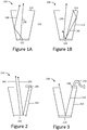
- Figure 1A illustrates a conventional light source 100.
- Conventional light source 100 comprises a light source 120 located inside a light pipe 110 comprising a reflective aperture 150.
- Light pipe 110 and light source 120 are configured to allow output light 130 to exit light pipe 110 in a cone of angles, and to prevent light exiting the light pipe outside of the cone of angles. The light may be prevented from exiting outside of the cone of angles by the presence of the reflective aperture 150. This is described with relation to Figure 1B .
- the reflective aperture 150 reflects incident light 140 that is incident onto aperture 140 such that the light is reflected back towards the light source 120, increasing the amount of useful power output from the conventional light source 100 by providing light recycling. This may a direct reflection from the reflective aperture 150 or indirect, via the sides of the light pipe 110.
- FIG. 2 illustrates a dynamic light source 200 in accordance with some examples.
- Dynamic light source 200 comprises a first device 210, a first light source 220 and a second light source 230.
- the first light source 220 is located inside first device 210 and the first device 210 is configured to allow light from the first light source 220 to exit the first device 210 in a first cone of angles 240.
- the first device 210 is further configured to reflect light incident outside the first cone of angles 240 back towards the first light source 220, similar to the conventional light source 100 described in relation to Figure 1 .
- Second light source 230 emits light towards the first light source 220, which is then reflected in a second cone of angles 250 substantially coincident with the first cone of angles. At least due to the fact that light emitted from the second light source 230 is reflected from the first light source 220, the output power of the second cone of angles 250 may be attenuated compared to the output power directly from the second light source 230. This may allow the dynamic light source 200 to have a dynamic range of power that is greater for the same current range than the dynamic range that would be allowed if the second light source 230 was not used. This is because the second light source 230 may be used to obtain the low power outputs that would conventionally require the first light source 220 to be driven with small electrical currents.
- the first light source 220 and the second light source 230 may be driven with substantially the same range of input currents, but may result in a different range of output powers from the light source 100. In some examples the output powers may differ by approximately an order of magnitude. In some examples the first light source 220 may be used to output light from the light source 200 in the range of ⁇ 0.01 A to ⁇ 1 A and the second light source may output light from the light source 200 in the range of ⁇ 1 micro A to ⁇ 0.01 A.
- the first device 210 comprises a homogenising light pipe. In some examples the first device 210 comprises a tapered light pipe.
- the first device 210 comprises an aperture to allow light to be output in the cone of angles.
- the second light source 230 is located substantially adjacent to the aperture.
- the first light source 220 comprises at least one light emitting diode (LED). In some examples the first light source comprises a plurality of LEDs mounted on a die.
- LED light emitting diode
- Figure 3 illustrates the dynamic light source 200 according to some examples, substantially similar to the description of Figure 2 , however the second light source 230 comprises a fibre optic cable 240.
- the fibre optic cable 240 may be used to couple the light from an external light source into the first device 210. This may allow a conventional light source 100, similar to that described with relation to Figure 1 to be adapted to have the same output power range with a smaller electrical current range without needing to add a second LED to the light source 100.
- the use of the fibre optic cable may also allow a smaller and simpler device.
Landscapes
- Physics & Mathematics (AREA)
- General Physics & Mathematics (AREA)
- Optics & Photonics (AREA)
- Engineering & Computer Science (AREA)
- Chemical & Material Sciences (AREA)
- Combustion & Propulsion (AREA)
- Transportation (AREA)
- Mechanical Engineering (AREA)
- Non-Portable Lighting Devices Or Systems Thereof (AREA)
Abstract
A dynamic light source for a display is disclosed. The dynamic light source comprises a first light source located inside a first device; and a second light source. The first device is configured to allow light from the first light source to exit the first device in a first cone of angles and to reflect light incident outside the cone of angles back towards the first light source. The first device is configured such that injected light from the second light source is reflected by the first light source in a second cone of angles substantially coincident with the first cone of angles.
Description
- For some applications it is desirable to have a light source that has a high range of output intensities, for example a light source for a head up display (HUD) or head mounted display (HMD).
-
-
Figures 1A and 1B illustrate a conventional light source. -
Figure 2 illustrates a light source in accordance with some examples. -
Figure 3 illustrates a light source comprising a fibre optic cable in accordance with some examples. -
Figure 1A illustrates aconventional light source 100.Conventional light source 100 comprises alight source 120 located inside alight pipe 110 comprising areflective aperture 150.Light pipe 110 andlight source 120 are configured to allowoutput light 130 to exitlight pipe 110 in a cone of angles, and to prevent light exiting the light pipe outside of the cone of angles. The light may be prevented from exiting outside of the cone of angles by the presence of thereflective aperture 150. This is described with relation toFigure 1B . - The
reflective aperture 150 reflectsincident light 140 that is incident ontoaperture 140 such that the light is reflected back towards thelight source 120, increasing the amount of useful power output from theconventional light source 100 by providing light recycling. This may a direct reflection from thereflective aperture 150 or indirect, via the sides of thelight pipe 110. - However, some applications use very high dynamic ranges of optical power and therefore high current ranges are required. In some examples a range of micro Amps to ∼1 Amp (a dynamic range of approximately 1:106). This may require very complicated and large electronics. This may be particularly problematic when the
conventional light source 100 is used on a HMD, as this could make the helmet bulky and heavy. -
Figure 2 illustrates adynamic light source 200 in accordance with some examples.Dynamic light source 200 comprises afirst device 210, afirst light source 220 and asecond light source 230. Thefirst light source 220 is located insidefirst device 210 and thefirst device 210 is configured to allow light from thefirst light source 220 to exit thefirst device 210 in a first cone ofangles 240. Thefirst device 210 is further configured to reflect light incident outside the first cone ofangles 240 back towards thefirst light source 220, similar to theconventional light source 100 described in relation toFigure 1 . -
Second light source 230 emits light towards thefirst light source 220, which is then reflected in a second cone ofangles 250 substantially coincident with the first cone of angles. At least due to the fact that light emitted from thesecond light source 230 is reflected from thefirst light source 220, the output power of the second cone ofangles 250 may be attenuated compared to the output power directly from thesecond light source 230. This may allow thedynamic light source 200 to have a dynamic range of power that is greater for the same current range than the dynamic range that would be allowed if thesecond light source 230 was not used. This is because thesecond light source 230 may be used to obtain the low power outputs that would conventionally require thefirst light source 220 to be driven with small electrical currents. - In some examples the
first light source 220 and thesecond light source 230 may be driven with substantially the same range of input currents, but may result in a different range of output powers from thelight source 100. In some examples the output powers may differ by approximately an order of magnitude. In some examples thefirst light source 220 may be used to output light from thelight source 200 in the range of ∼0.01 A to ∼1 A and the second light source may output light from thelight source 200 in the range of ∼1 micro A to ∼0.01 A. - In some examples the
first device 210 comprises a homogenising light pipe. In some examples thefirst device 210 comprises a tapered light pipe. - In some examples the
first device 210 comprises an aperture to allow light to be output in the cone of angles. In some examples thesecond light source 230 is located substantially adjacent to the aperture. - In some examples the
first light source 220 comprises at least one light emitting diode (LED). In some examples the first light source comprises a plurality of LEDs mounted on a die. -
Figure 3 illustrates thedynamic light source 200 according to some examples, substantially similar to the description ofFigure 2 , however thesecond light source 230 comprises a fibreoptic cable 240. The fibreoptic cable 240 may be used to couple the light from an external light source into thefirst device 210. This may allow aconventional light source 100, similar to that described with relation toFigure 1 to be adapted to have the same output power range with a smaller electrical current range without needing to add a second LED to thelight source 100. The use of the fibre optic cable may also allow a smaller and simpler device. - Although the present invention has been described in connection with some embodiments, it is not intended to be limited to the specific form set forth herein. Rather, the scope of the present invention is limited only by the accompanying claims. Additionally, although a feature may appear to be described in connection with particular embodiments, one skilled in the art would recognize that various features of the described embodiments may be combined in accordance with the invention. In the claims, the term 'comprising' does not exclude the presence of other elements or steps.
- Furthermore, the order of features in the claims does not imply any specific order in which the features must be performed and in particular the order of individual steps in a method claim does not imply that the steps must be performed in this order. Rather, the steps may be performed in any suitable order. In addition, singular references do not exclude a plurality. Thus, references to 'a', 'an', 'first', 'second', etc. do not preclude a plurality. In the claims, the term 'comprising' or "including" does not exclude the presence of other elements.
Claims (10)
- A dynamic light source for a display, the light source comprising:
a first light source located inside a first device; a second light source;wherein the first device is configured to allow light from the first light source to exit the first device in a first cone of angles and to reflect light incident outside the cone of angles back towards the first light source;wherein the first device is configured such that injected light from the second light source is reflected by the first light source in a second cone of angles substantially coincident with the first cone of angles. - The dynamic light source according to claim 1, wherein the first device comprises a homogenising light pipe.
- The dynamic light source according to any of claims 1 or 2, wherein first device comprises a tapered light pipe.
- The dynamic light source according to any of claims 1-3, wherein the first device comprises an aperture to allow light to be output in the cone of angles.
- The dynamic light source according to claim 4, wherein the second light source is located substantially adjacent to the aperture.
- The dynamic light source according to any of claims 1-5, wherein the second light source comprises a fibre optic cable.
- The dynamic light source according to claim 6, wherein the fibre optic cable is coupled to an external light source.
- The dynamic light source according to any of claims 1-7, wherein the first light source comprises at least one light emitting diode
- The dynamic light source according to any of claims 1-8, wherein the first light source comprises a die comprising a plurality of light emitting diodes
- The dynamic light source according to any of claims 1-9, wherein the first light source and second light source operate using substantially the same range of drive currents.
Priority Applications (6)
| Application Number | Priority Date | Filing Date | Title |
|---|---|---|---|
| EP19275144.4A EP3831637A1 (en) | 2019-12-06 | 2019-12-06 | Light source |
| GB2018163.2A GB2591846B (en) | 2019-12-06 | 2020-11-19 | Light source |
| EP20811430.6A EP4069546B1 (en) | 2019-12-06 | 2020-11-19 | Light source |
| PCT/GB2020/052949 WO2021111103A1 (en) | 2019-12-06 | 2020-11-19 | Light source |
| ES20811430T ES3001533T3 (en) | 2019-12-06 | 2020-11-19 | Light source |
| US17/756,827 US11828455B2 (en) | 2019-12-06 | 2020-11-19 | Light source |
Applications Claiming Priority (1)
| Application Number | Priority Date | Filing Date | Title |
|---|---|---|---|
| EP19275144.4A EP3831637A1 (en) | 2019-12-06 | 2019-12-06 | Light source |
Publications (1)
| Publication Number | Publication Date |
|---|---|
| EP3831637A1 true EP3831637A1 (en) | 2021-06-09 |
Family
ID=68835123
Family Applications (1)
| Application Number | Title | Priority Date | Filing Date |
|---|---|---|---|
| EP19275144.4A Pending EP3831637A1 (en) | 2019-12-06 | 2019-12-06 | Light source |
Country Status (1)
| Country | Link |
|---|---|
| EP (1) | EP3831637A1 (en) |
Citations (7)
| Publication number | Priority date | Publication date | Assignee | Title |
|---|---|---|---|---|
| US20020027779A1 (en) * | 1999-07-02 | 2002-03-07 | Cassarly William J. | Image generator having an improved illumination system |
| US20040232812A1 (en) * | 2003-05-23 | 2004-11-25 | Beeson Karl W. | Illumination systems utilizing light emitting diodes and light recycling to enhance output radiance |
| US20040233664A1 (en) * | 2003-05-23 | 2004-11-25 | Beeson Karl W. | Illumination systems utilizing multiple wavelength light recycling |
| US20050219476A1 (en) * | 2004-03-30 | 2005-10-06 | Beeson Karl W | Projection display systems utilizing light emitting diodes and light recycling |
| JP2011039395A (en) * | 2009-08-17 | 2011-02-24 | Canon Inc | Illuminator and image display device having the same |
| US20130021793A1 (en) * | 2011-07-22 | 2013-01-24 | Zimmerman Scott M | Recycling light cavity with enhanced reflectivity |
| US20170045740A1 (en) * | 2014-05-09 | 2017-02-16 | Hitachi Maxell, Ltd. | Head-up display device |
-
2019
- 2019-12-06 EP EP19275144.4A patent/EP3831637A1/en active Pending
Patent Citations (7)
| Publication number | Priority date | Publication date | Assignee | Title |
|---|---|---|---|---|
| US20020027779A1 (en) * | 1999-07-02 | 2002-03-07 | Cassarly William J. | Image generator having an improved illumination system |
| US20040232812A1 (en) * | 2003-05-23 | 2004-11-25 | Beeson Karl W. | Illumination systems utilizing light emitting diodes and light recycling to enhance output radiance |
| US20040233664A1 (en) * | 2003-05-23 | 2004-11-25 | Beeson Karl W. | Illumination systems utilizing multiple wavelength light recycling |
| US20050219476A1 (en) * | 2004-03-30 | 2005-10-06 | Beeson Karl W | Projection display systems utilizing light emitting diodes and light recycling |
| JP2011039395A (en) * | 2009-08-17 | 2011-02-24 | Canon Inc | Illuminator and image display device having the same |
| US20130021793A1 (en) * | 2011-07-22 | 2013-01-24 | Zimmerman Scott M | Recycling light cavity with enhanced reflectivity |
| US20170045740A1 (en) * | 2014-05-09 | 2017-02-16 | Hitachi Maxell, Ltd. | Head-up display device |
Similar Documents
| Publication | Publication Date | Title |
|---|---|---|
| US11828455B2 (en) | Light source | |
| US7884985B2 (en) | High brightness optical device | |
| US9417391B2 (en) | Optical combiner and laser device using the same | |
| TWI479215B (en) | Fiber connector | |
| US9651854B2 (en) | Projector | |
| WO2020101760A3 (en) | Scanning lidar systems with moving lens assembly | |
| KR101880070B1 (en) | A device for simultaneous data and power transmission over an optical waveguide | |
| US20160327721A1 (en) | Optical fiber lighting device and method | |
| GB2510370A (en) | Fibre Optical Laser Combiner | |
| EP2343594A3 (en) | A camera flash, a camera, and a method of generating a flash | |
| CN107923599B (en) | Lighting device for a vehicle headlight | |
| US20200251880A1 (en) | Laser module and laser system | |
| CN104501096A (en) | Reflecting transmission device and laser backlight source with same | |
| Nakatsu et al. | Edge-emitting blue laser diode with high CW wall-plug efficiency of 50% | |
| WO2019130060A3 (en) | Fiber optic photon engine | |
| US9690060B2 (en) | Optical fiber connector and optical coupling lens | |
| US20170063037A1 (en) | Light emission module | |
| CN206369871U (en) | A high-power RGB synthetic laser light source system | |
| CN202305904U (en) | Optical fiber connector of light-emitting diode (LED) light source | |
| Könning et al. | Kilowatt-class high power fiber-coupled diode lasers at 450nm | |
| US9448351B2 (en) | Reflector, illuminating device and backlight module using the reflector | |
| CN204966964U (en) | White light laser module, laser display system and laser projection system | |
| CN103091790B (en) | Light-emitting diode (LED) light source optical fiber connector | |
| CN205787405U (en) | A kind of device eliminating laser speckle | |
| US20210033870A1 (en) | Optical device and image display apparatus |
Legal Events
| Date | Code | Title | Description |
|---|---|---|---|
| PUAI | Public reference made under article 153(3) epc to a published international application that has entered the european phase |
Free format text: ORIGINAL CODE: 0009012 |
|
| STAA | Information on the status of an ep patent application or granted ep patent |
Free format text: STATUS: THE APPLICATION HAS BEEN PUBLISHED |
|
| AK | Designated contracting states |
Kind code of ref document: A1 Designated state(s): AL AT BE BG CH CY CZ DE DK EE ES FI FR GB GR HR HU IE IS IT LI LT LU LV MC MK MT NL NO PL PT RO RS SE SI SK SM TR |