EP3831595A1 - Heat dissipation sheet and method of manufacturing heat dissipation sheet - Google Patents
Heat dissipation sheet and method of manufacturing heat dissipation sheet Download PDFInfo
- Publication number
- EP3831595A1 EP3831595A1 EP20208044.6A EP20208044A EP3831595A1 EP 3831595 A1 EP3831595 A1 EP 3831595A1 EP 20208044 A EP20208044 A EP 20208044A EP 3831595 A1 EP3831595 A1 EP 3831595A1
- Authority
- EP
- European Patent Office
- Prior art keywords
- adhesive resin
- heat dissipation
- dissipation sheet
- resin layer
- carbon materials
- Prior art date
- Legal status (The legal status is an assumption and is not a legal conclusion. Google has not performed a legal analysis and makes no representation as to the accuracy of the status listed.)
- Granted
Links
Images









Classifications
-
- H—ELECTRICITY
- H05—ELECTRIC TECHNIQUES NOT OTHERWISE PROVIDED FOR
- H05K—PRINTED CIRCUITS; CASINGS OR CONSTRUCTIONAL DETAILS OF ELECTRIC APPARATUS; MANUFACTURE OF ASSEMBLAGES OF ELECTRICAL COMPONENTS
- H05K7/00—Constructional details common to different types of electric apparatus
- H05K7/20—Modifications to facilitate cooling, ventilating, or heating
- H05K7/2039—Modifications to facilitate cooling, ventilating, or heating characterised by the heat transfer by conduction from the heat generating element to a dissipating body
-
- B—PERFORMING OPERATIONS; TRANSPORTING
- B32—LAYERED PRODUCTS
- B32B—LAYERED PRODUCTS, i.e. PRODUCTS BUILT-UP OF STRATA OF FLAT OR NON-FLAT, e.g. CELLULAR OR HONEYCOMB, FORM
- B32B7/00—Layered products characterised by the relation between layers; Layered products characterised by the relative orientation of features between layers, or by the relative values of a measurable parameter between layers, i.e. products comprising layers having different physical, chemical or physicochemical properties; Layered products characterised by the interconnection of layers
- B32B7/04—Interconnection of layers
- B32B7/12—Interconnection of layers using interposed adhesives or interposed materials with bonding properties
-
- B—PERFORMING OPERATIONS; TRANSPORTING
- B32—LAYERED PRODUCTS
- B32B—LAYERED PRODUCTS, i.e. PRODUCTS BUILT-UP OF STRATA OF FLAT OR NON-FLAT, e.g. CELLULAR OR HONEYCOMB, FORM
- B32B27/00—Layered products comprising a layer of synthetic resin
- B32B27/06—Layered products comprising a layer of synthetic resin as the main or only constituent of a layer, which is next to another layer of the same or of a different material
- B32B27/08—Layered products comprising a layer of synthetic resin as the main or only constituent of a layer, which is next to another layer of the same or of a different material of synthetic resin
-
- B—PERFORMING OPERATIONS; TRANSPORTING
- B32—LAYERED PRODUCTS
- B32B—LAYERED PRODUCTS, i.e. PRODUCTS BUILT-UP OF STRATA OF FLAT OR NON-FLAT, e.g. CELLULAR OR HONEYCOMB, FORM
- B32B27/00—Layered products comprising a layer of synthetic resin
- B32B27/38—Layered products comprising a layer of synthetic resin comprising epoxy resins
-
- B—PERFORMING OPERATIONS; TRANSPORTING
- B32—LAYERED PRODUCTS
- B32B—LAYERED PRODUCTS, i.e. PRODUCTS BUILT-UP OF STRATA OF FLAT OR NON-FLAT, e.g. CELLULAR OR HONEYCOMB, FORM
- B32B37/00—Methods or apparatus for laminating, e.g. by curing or by ultrasonic bonding
- B32B37/02—Methods or apparatus for laminating, e.g. by curing or by ultrasonic bonding characterised by a sequence of laminating steps, e.g. by adding new layers at consecutive laminating stations
- B32B37/025—Transfer laminating
-
- B—PERFORMING OPERATIONS; TRANSPORTING
- B32—LAYERED PRODUCTS
- B32B—LAYERED PRODUCTS, i.e. PRODUCTS BUILT-UP OF STRATA OF FLAT OR NON-FLAT, e.g. CELLULAR OR HONEYCOMB, FORM
- B32B7/00—Layered products characterised by the relation between layers; Layered products characterised by the relative orientation of features between layers, or by the relative values of a measurable parameter between layers, i.e. products comprising layers having different physical, chemical or physicochemical properties; Layered products characterised by the interconnection of layers
- B32B7/04—Interconnection of layers
- B32B7/06—Interconnection of layers permitting easy separation
-
- C—CHEMISTRY; METALLURGY
- C09—DYES; PAINTS; POLISHES; NATURAL RESINS; ADHESIVES; COMPOSITIONS NOT OTHERWISE PROVIDED FOR; APPLICATIONS OF MATERIALS NOT OTHERWISE PROVIDED FOR
- C09J—ADHESIVES; NON-MECHANICAL ASPECTS OF ADHESIVE PROCESSES IN GENERAL; ADHESIVE PROCESSES NOT PROVIDED FOR ELSEWHERE; USE OF MATERIALS AS ADHESIVES
- C09J7/00—Adhesives in the form of films or foils
- C09J7/20—Adhesives in the form of films or foils characterised by their carriers
-
- B—PERFORMING OPERATIONS; TRANSPORTING
- B32—LAYERED PRODUCTS
- B32B—LAYERED PRODUCTS, i.e. PRODUCTS BUILT-UP OF STRATA OF FLAT OR NON-FLAT, e.g. CELLULAR OR HONEYCOMB, FORM
- B32B2250/00—Layers arrangement
- B32B2250/02—2 layers
-
- B—PERFORMING OPERATIONS; TRANSPORTING
- B32—LAYERED PRODUCTS
- B32B—LAYERED PRODUCTS, i.e. PRODUCTS BUILT-UP OF STRATA OF FLAT OR NON-FLAT, e.g. CELLULAR OR HONEYCOMB, FORM
- B32B2250/00—Layers arrangement
- B32B2250/04—4 layers
-
- B—PERFORMING OPERATIONS; TRANSPORTING
- B32—LAYERED PRODUCTS
- B32B—LAYERED PRODUCTS, i.e. PRODUCTS BUILT-UP OF STRATA OF FLAT OR NON-FLAT, e.g. CELLULAR OR HONEYCOMB, FORM
- B32B2250/00—Layers arrangement
- B32B2250/40—Symmetrical or sandwich layers, e.g. ABA, ABCBA, ABCCBA
-
- B—PERFORMING OPERATIONS; TRANSPORTING
- B32—LAYERED PRODUCTS
- B32B—LAYERED PRODUCTS, i.e. PRODUCTS BUILT-UP OF STRATA OF FLAT OR NON-FLAT, e.g. CELLULAR OR HONEYCOMB, FORM
- B32B2262/00—Composition or structural features of fibres which form a fibrous or filamentary layer or are present as additives
- B32B2262/10—Inorganic fibres
- B32B2262/106—Carbon fibres, e.g. graphite fibres
-
- B—PERFORMING OPERATIONS; TRANSPORTING
- B32—LAYERED PRODUCTS
- B32B—LAYERED PRODUCTS, i.e. PRODUCTS BUILT-UP OF STRATA OF FLAT OR NON-FLAT, e.g. CELLULAR OR HONEYCOMB, FORM
- B32B2264/00—Composition or properties of particles which form a particulate layer or are present as additives
- B32B2264/10—Inorganic particles
- B32B2264/107—Ceramic
- B32B2264/108—Carbon, e.g. graphite particles
-
- B—PERFORMING OPERATIONS; TRANSPORTING
- B32—LAYERED PRODUCTS
- B32B—LAYERED PRODUCTS, i.e. PRODUCTS BUILT-UP OF STRATA OF FLAT OR NON-FLAT, e.g. CELLULAR OR HONEYCOMB, FORM
- B32B2307/00—Properties of the layers or laminate
- B32B2307/30—Properties of the layers or laminate having particular thermal properties
- B32B2307/302—Conductive
-
- B—PERFORMING OPERATIONS; TRANSPORTING
- B32—LAYERED PRODUCTS
- B32B—LAYERED PRODUCTS, i.e. PRODUCTS BUILT-UP OF STRATA OF FLAT OR NON-FLAT, e.g. CELLULAR OR HONEYCOMB, FORM
- B32B2307/00—Properties of the layers or laminate
- B32B2307/70—Other properties
- B32B2307/72—Density
-
- B—PERFORMING OPERATIONS; TRANSPORTING
- B32—LAYERED PRODUCTS
- B32B—LAYERED PRODUCTS, i.e. PRODUCTS BUILT-UP OF STRATA OF FLAT OR NON-FLAT, e.g. CELLULAR OR HONEYCOMB, FORM
- B32B2307/00—Properties of the layers or laminate
- B32B2307/70—Other properties
- B32B2307/732—Dimensional properties
-
- B—PERFORMING OPERATIONS; TRANSPORTING
- B32—LAYERED PRODUCTS
- B32B—LAYERED PRODUCTS, i.e. PRODUCTS BUILT-UP OF STRATA OF FLAT OR NON-FLAT, e.g. CELLULAR OR HONEYCOMB, FORM
- B32B2405/00—Adhesive articles, e.g. adhesive tapes
-
- B—PERFORMING OPERATIONS; TRANSPORTING
- B32—LAYERED PRODUCTS
- B32B—LAYERED PRODUCTS, i.e. PRODUCTS BUILT-UP OF STRATA OF FLAT OR NON-FLAT, e.g. CELLULAR OR HONEYCOMB, FORM
- B32B2457/00—Electrical equipment
-
- B—PERFORMING OPERATIONS; TRANSPORTING
- B32—LAYERED PRODUCTS
- B32B—LAYERED PRODUCTS, i.e. PRODUCTS BUILT-UP OF STRATA OF FLAT OR NON-FLAT, e.g. CELLULAR OR HONEYCOMB, FORM
- B32B3/00—Layered products comprising a layer with external or internal discontinuities or unevennesses, or a layer of non-planar shape; Layered products comprising a layer having particular features of form
- B32B3/02—Layered products comprising a layer with external or internal discontinuities or unevennesses, or a layer of non-planar shape; Layered products comprising a layer having particular features of form characterised by features of form at particular places, e.g. in edge regions
- B32B3/08—Layered products comprising a layer with external or internal discontinuities or unevennesses, or a layer of non-planar shape; Layered products comprising a layer having particular features of form characterised by features of form at particular places, e.g. in edge regions characterised by added members at particular parts
- B32B3/085—Layered products comprising a layer with external or internal discontinuities or unevennesses, or a layer of non-planar shape; Layered products comprising a layer having particular features of form characterised by features of form at particular places, e.g. in edge regions characterised by added members at particular parts spaced apart pieces on the surface of a layer
-
- C—CHEMISTRY; METALLURGY
- C09—DYES; PAINTS; POLISHES; NATURAL RESINS; ADHESIVES; COMPOSITIONS NOT OTHERWISE PROVIDED FOR; APPLICATIONS OF MATERIALS NOT OTHERWISE PROVIDED FOR
- C09J—ADHESIVES; NON-MECHANICAL ASPECTS OF ADHESIVE PROCESSES IN GENERAL; ADHESIVE PROCESSES NOT PROVIDED FOR ELSEWHERE; USE OF MATERIALS AS ADHESIVES
- C09J2400/00—Presence of inorganic and organic materials
- C09J2400/10—Presence of inorganic materials
Definitions
- Embodiments discussed herein are related to a heat dissipation sheet and a method of manufacturing a heat dissipation sheet.
- a transfer sheet for transferring a heat conductive material layer made of a carbon material to a member having a heat generating portion
- a transfer sheet for transferring a heat conductive material layer made of a carbon material to a member having a heat generating portion
- the transfer sheet disclosed in International Publication Pamphlet No. WO 2018/110255 has a structure in which a release layer made of a release film, a first adhesive layer, a heat conductive material layer, and a second adhesive layer are laminated in this order.
- an object of the embodiments disclosed in the present specification is to ensure adhesiveness to a heating element and a heat dissipation element and thermal conductivity between the heating element and the heat dissipation element.
- a heat dissipation sheet includes a carbon material layer configured to include a plurality of linear carbon materials arranged in parallel with each other, an adhesive resin layer configured to include a first surface to be in contact with an end of each of the plurality of linear carbon materials, a thickness of the adhesive resin layer being less than 1 ⁇ m, and a release sheet configured to be in contact with a second surface among a plurality of surfaces of the adhesive resin layer, the second surface being over a side opposite to the first surface.
- a heat dissipation sheet is demanded to have favorable thermal conductivity between a heating element such as a semiconductor chip and a heat dissipation element such as a heat spreader, and have adhesiveness for fixing the heat dissipation element to the heating element.
- the transfer sheet disclosed in International Publication Pamphlet No. WO 2018/110255 has room for improvement in terms of achieving both favorable thermal conductivity and adhesiveness.
- the heat dissipation sheet 100 includes a heat dissipation sheet body 1, a first release sheet 6 provided on one surface side of the heat dissipation sheet body 1, and a second release sheet 7 provided on the other surface side of the heat dissipation sheet body 1.
- the heat dissipation sheet 100 is disposed between a heating element 31 (refer to FIG. 21 ) represented by an electronic component that generates heat, such as a central processing unit (CPU), and a heat dissipation element 32 (refer to FIG.
- the heat dissipation sheet body 1 includes a carbon nanotube layer (hereinafter referred to as a "CNT layer") 2 as a carbon material layer.
- the CNT layer 2 is formed by gathering a plurality of carbon nanotubes (hereinafter referred to as "CNTs") 3 as a plurality of linear carbon materials into a sheet shape. Since the plurality of CNTs 3 extend substantially in the same direction, the CNT layer may be formed by planarly spreading the plurality of CNTs 3 in a sheet shape.
- the CNT 3 may be a single layer or a multilayer.
- the surface density of the CNTs 3 is 1 ⁇ 10 10 pieces/cm 2 or more. This is in consideration of heat dissipation and electrical conductivity.
- the surface density of the CNTs 3, for example, the number of CNTs 3 depends on the amount of paths for heat dissipation and electrical conduction, and as the number of CNTs 3 is increased, the heat dissipation and electrical conductivity become more dominant.
- the heat dissipation sheet 100 of the present embodiment is used for heat conduction between the heating element 31 and the heat dissipation element 32, but by setting the surface density of the CNTs 3 to be 1 ⁇ 10 10 pieces/cm 2 or more, characteristics suitable for this use may be provided.
- the interval between the CNTs 3 is drawn to be substantially uniform, but in reality, since the CNTs 3 grow randomly, the distance between the adjacent CNTs 3 may not be uniform.
- each CNT 3 is substantially equal to the thickness tc of the CNT layer 2.
- the thickness tc may be appropriately set according to the use of the heat dissipation sheet 100, and may be set in a range of approximately 100 ⁇ m to 500 ⁇ m.
- a gap 8 is formed between the adjacent CNTs 3. This improves the contractility of the CNT layer 2.
- the CNT layer 2 easily follows the expansion and contraction of the heat dissipation sheet 1 caused by a thermal cycle in which the rise and fall of the temperature are repeated.
- Each linear CNT 3 has a first end 3a, and a second end 3b located on a side opposite to the first end 3a.
- a first end surface 3a1 is formed at the first end 3a, and a second end surface 3b1 is formed at the second end 3b.
- a first adhesive resin 4 is provided on the first end 3a side.
- the first adhesive resin 4 may be an epoxy resin.
- the first adhesive resin 4 includes a first adhesive resin layer 4a, and an embedded portion 4b continuous with the first adhesive resin layer 4a.
- the first adhesive resin layer 4a has a first surface, and a second surface on a side opposite to the first surface.
- the first surface is a first holding surface 4a1 for holding each CNT 3, and the embedded portion 4b is provided at the first holding surface 4a1.
- the first end 3a (first end surface 3a1) of each CNT 3 is in contact with the first holding surface 4a1, and the embedded portion 4b is provided around the first end 3a so that the first end 3a is embedded.
- each CNT 3 is held by the first adhesive resin 4, and each CNT 3 and the first adhesive resin 4 are firmly integrated.
- the second surface of the first adhesive resin layer 4a is a first adhesive surface 4a2.
- the first adhesive surface 4a2 is located on a side opposite to the embedded portion 4b, and the first release sheet 6 is attached to the first adhesive surface 4a2 when the heat dissipation sheet 100 is in an unused state, for example, when the heat dissipation sheet 100 is for sale.
- the first release sheet 6 is a film-like member, and is peeled off in the use state of the heat dissipation sheet 100, and the first adhesive surface 4a2 is bonded to the heating element 31 or the heat dissipation element 32 (refer to FIG. 21 ).
- a second adhesive resin 5 is provided on the second end 3b side.
- the second adhesive resin 5 may be an epoxy resin.
- the second adhesive resin 5 includes a second adhesive resin layer 5a, and an embedded portion 5b continuous with the second adhesive resin layer 5a.
- the second adhesive resin layer 5a has a third surface, and a fourth surface on a side opposite to the third surface.
- the fourth surface is a second holding surface 5a1 for holding each CNT 3, and the embedded portion 5b is provided at the second holding surface 5a1.
- the second end 3b (second end surface 3b1) of each CNT 3 is in contact with the second holding surface 5a1, and the embedded portion 5b is provided around the second end 3b so that the second end 3b is embedded.
- each CNT 3 is held by the second adhesive resin 5, and each CNT 3 and the second adhesive resin 5 are firmly integrated.
- the third surface of the second adhesive resin layer 5a is a second adhesive surface 5a2.
- the second adhesive surface 5a2 is located on a side opposite to the embedded portion 5b, and the second release sheet 7 is attached to the second adhesive surface 5a2 when the heat dissipation sheet 100 is in an unused state, for example, when the heat dissipation sheet 100 is for sale.
- the second release sheet 7 is a film-like member, and is peeled off in the use state of the heat dissipation sheet 100, and the second adhesive surface 5a2 is bonded to the heating element 31 or the heat dissipation element 32 (refer to FIG. 21 ).
- the thickness S of the first adhesive resin layer 4a is less than 1 ⁇ m. Since the first adhesive resin layer 4a is present, the thickness S does not become 0 ⁇ m.
- a state in which the thickness S of the first adhesive resin layer 4a is 0 ⁇ m means a state in which the first end surface 3a1 is exposed to the first adhesive surface 4a2. When the first end surface 3a1 is exposed to the first adhesive surface 4a2, the adhesiveness is affected. Therefore, it is not desirable that the first end surface 3a1 is exposed to the first adhesive surface 4a2. Thus, in the present embodiment, the thickness S of the first adhesive resin layer 4a is made not to be 0 ⁇ m.
- the thickness S of the first adhesive resin layer 4a is preferably as thin as possible from the viewpoint of improving thermal conductivity.
- FIG. 3 the dependency of the thermal resistance of the heat dissipation sheet 100 on the thickness of the adhesive resin layer will be described. Referring to FIG. 3 , it may be seen that the thermal resistance is increased as the thickness of the adhesive resin layer is increased. Therefore, the thickness S of the adhesive resin layer is desirably as thin as possible. Thus, in the present embodiment, the thickness S is less than 1 ⁇ m.
- the thickness S of the adhesive resin layer is preferably as thin as possible, and is preferably set in a range of 200 nm to 800 nm.
- the thickness S of the adhesive resin layer may also be referred to as a distance between the end surface of each CNT and the adhesive surface of the adhesive resin layer.
- the thickness S of the second adhesive resin layer 5a is 1 ⁇ m, and the thickness S is made not to be 0 ⁇ m. Since the properties demanded for the second adhesive resin layer 5a are the same as those of the first adhesive resin layer 4a, detailed description thereof will be omitted.
- the CNT layer 2 using the CNTs 3 is provided.
- Each CNT 3 is a material having very high heat conductivity (1500 to 3000 W/m ⁇ K) as well as excellent flexibility and heat resistance, and has properties suitable for a heat dissipation material.
- high thermal conductivity is achieved by adopting such a CNT 3 and setting the thickness S of each of the first adhesive resin layer 4a and the second adhesive resin layer 5a to be less than 1 ⁇ m. Since the first end surface 3a1 of the CNT 3 is not exposed to the first adhesive surface 4a2 and similarly, the second end surface 3b1 is not exposed to the second adhesive surface 5a2, the adhesiveness of each adhesive surface is ensured.
- a plurality of CNTs 3 are formed over a first substrate 10.
- Each CNT 3 has the first end 3a on the first substrate 10 side and the second end 3b on the opposite side.
- a silicon substrate is used as the first substrate 10.
- a semiconductor substrate such as a silicon substrate, an alumina (sapphire) substrate, a magnesium oxide (MgO) substrate, a glass substrate, a metal substrate such as a stainless steel substrate, stainless steel foil, aluminum foil, or the like may be used.
- a thin film may be formed over the substrate.
- a silicon substrate over which a silicon oxide film having a film thickness of about 300 nm is formed may be used.
- the first substrate 10 is peeled off after the CNT 3 is formed.
- the first substrate 10 does not change in quality at the formation temperature of the CNT 3, and at least the surface of the first substrate 10 which is in contact with the first end 3a of the CNT 3 is made of a material that may be easily peeled off from the CNT 3.
- the first substrate 10 may be made of a material that may be selectively etched with respect to the CNT 3.
- an Al (aluminum) film having a film thickness of 1.0 nm is formed and a Fe (iron) film having a film thickness of 2.5 nm is formed, thereby forming a catalyst metal film made of Fe on the Al film as a base.
- Methods other than sputtering may be adopted, and the film thickness is not limited to 2.5 mm.
- Co (cobalt), Ni (nickel), Au (gold), Ag (silver), Pt (platinum), or an alloy containing at least one of these materials may be used as the catalyst metal.
- metal fine particles prepared by controlling the size in advance using a differential mobility analyzer (DMA) or the like may be used.
- the metal species may be the same as that of the thin film.
- a laminated structure of Fe (2.5 nm)/AI (10 nm), a laminated structure of Co (2.6 nm)/TiN (5 nm), or the like may be applied.
- a laminated structure of Co (average diameter 3.8 nm)/TiN (5 nm) may be applied.
- the CNT 3 is grown over the substrate by, for example, hot filament CVD using the catalyst metal film as the catalyst.
- the growth conditions for the CNT 3 are that, for example, a mixed gas of acetylene and argon (partial pressure ratio 1:9) is used as a source gas, the total gas pressure in a film forming chamber is 1 kPa, the hot filament temperature is 1000°C, and the growth time is 20 minutes.
- multi-layered CNTs 3 having 3 to 6 layers (about 4 layers on average), a diameter of 4 to 8 nm (6 nm on average), and a length of 80 ⁇ m (growth rate: 4 ⁇ m/min) may be grown.
- the CNT 3 may be formed by other methods for film formation such as thermal CVD or remote plasma CVD.
- the CNT 3 to be grown may be a single layer.
- hydrocarbons such as methane and ethylene, alcohols such as ethanol and methanol, and the like may be used as the carbon raw material.
- a plurality of carbon nanotubes oriented substantially perpendicular to the surface of the first substrate 10 are formed over a region of the first substrate 10 where the catalyst metal film is formed.
- the surface density of the CNTs 3 was about 1 ⁇ 10 10 pieces/cm 2 .
- the gap 8 was formed between the adjacent CNTs 3.
- a portion apart from the first substrate 10 is the second end 3b, and a tip portion thereof is the second end surface 3b1. Due to the growth mechanism of the CNTs 3, the tip ends of the CNTs 3 may be mixed in the lateral direction, and in this case, a portion farthest from the first substrate 10 is defined as the second end surface 3b1.
- a transfer member 11 is brought into contact with the second end surface 3b1 of each second end 3b of the CNTs 3 grown over the first substrate 10, and is pressed toward the first substrate 10 as indicated by arrows 12.
- the transfer member 11 in the present embodiment is a silicone rubber sheet, but other materials such as natural rubbers and synthetic rubbers may be used as the transfer member as long as the material may transfer the CNTs 3.
- the first adhesive resin 4 which is an epoxy resin, is provided over a second substrate 14.
- the second substrate 14 is a silicon substrate.
- the first release sheet 6 is disposed over the first adhesive surface 4a2 of the first adhesive resin 4.
- the first adhesive resin 4 is disposed such that the first release sheet 6 is brought into contact with the second substrate 14 and the first adhesive resin 4 is located on the upper side.
- the first adhesive resin 4 is fixed over the second substrate 14 with a heat-resistant tape 15.
- the CNTs 3 transferred to the transfer member 11 are disposed over the first adhesive resin 4, and are pressed toward the second substrate 14 as indicated by arrows 16. In this manner, the first end surface 3a1 of each first end 3a is brought into close contact with the first adhesive resin 4.
- the second substrate 14 is mounted over a hot plate 17.
- the second substrate 14 is heated by the hot plate 17.
- the first adhesive resin 4 is softened.
- the temperature of the hot plate 17 is adjusted such that the first adhesive resin 4 is softened to be in a low viscosity state.
- the adhesion of the first adhesive resin 4 is increased. In this state, when the transfer member 11 is pressed toward the second substrate 14 as indicated by arrows 18, the first end 3a of each CNT 3 is held by the first adhesive resin 4.
- the heat of the hot plate 17 is also transferred to the transfer member 11 through the first adhesive resin 4 and the CNTs 3.
- the transfer member 11 is softened and the transfer member 11 may be removed from the second ends 3b of the CNTs 3.
- the plurality of CNTs 3 may be transferred to the first adhesive resin 4.
- the second adhesive resin 5 having the second adhesive surface 5a2 where the second release sheet 7 is disposed over the second end surface 3b1 formed at the second end 3b of each CNT 3.
- the second substrate 14 is heated over the hot plate 17.
- the temperature at this time is the same as the temperature when the second substrate 14 is heated in FIGs. 8 to 10 .
- the heat of the hot plate 17 is also transferred to the second adhesive resin 5 through the first adhesive resin 4 and the CNTs 3.
- the second adhesive resin 5 is softened.
- the adhesion of the second adhesive resin 5 is increased. In this state, when the second adhesive resin 5 is pressed toward the second substrate 14 as indicated by arrows 20, the second end 3b of each CNT 3 is held by the second adhesive resin 5.
- the second substrate 14 is taken off of the hot plate 17, and is cooled. At this time, the first end 3a of the CNT 3 is held by the first adhesive resin 4, and the second end 3b of the CNT 3 is held by the second adhesive resin 5.
- the second substrate 14 is mounted over the hot plate 17 again, and the second substrate 14 is heated.
- the heat of the hot plate 17 is also transferred to the first adhesive resin 4 and the second adhesive resin 5, the temperature of each of the first adhesive resin 4 and the second adhesive resin 5 is set to be higher than that when the second substrate 14 is heated in FIGs. 8 to 10 , 12 , and 13 .
- the hot plate 17 may be provided over the second release sheet 7.
- the first adhesive resin layer 4a is formed between the first end surface 3a1 and the first adhesive surface 4a2 by adjusting the distance between the first end surface 3a1 and the first adhesive surface 4a2 while adjusting the temperature of the first adhesive resin 4.
- the second adhesive resin layer 5a is formed between the second end surface 3b1 and the second adhesive surface 5a2 by adjusting the distance between the second end surface 3b1 and the second adhesive surface 5a2 while adjusting the temperature of the second adhesive resin 5.
- each of the first adhesive resin 4 and the second adhesive resin 5 is adjusted because the distance between the first end surface 3a1 and the first adhesive surface 4a2 and the distance between the second end surface 3b1 and the second adhesive surface 5a2 have a correlation with the temperature.
- the second adhesive resin 5 when the second adhesive resin 5 is heated to an appropriate temperature and is pressed as indicated by arrows 21 in FIG. 14 , a second adhesive resin layer 5a having a thickness S of less than 1 ⁇ m is formed.
- the second adhesive resin enters between the CNTs 3 by capillary phenomenon to form the embedded portion 5b continuous with the second adhesive resin layer 5a, and the second end 3b of the CNT 3 is embedded and fixed in the embedded portion 5b.
- the thickness S may be set to be less than 1 ⁇ m because the second adhesive resin 5 is heated to an appropriate temperature and is appropriately softened to have a low viscosity, so that the second end 3b of the CNT 3 is appropriately inserted into the softened second adhesive resin 5.
- the second adhesive resin 5 is illustrated in FIGs. 15 and 16 for convenience of description, the same phenomenon occurs in the first adhesive resin 4 so that the first adhesive resin layer 4a is formed and the embedded portion 4b is formed. The first end 3a is embedded and fixed in the embedded portion 4b.
- the thickness S becomes 1 ⁇ m or more. It is considered that this is because when the temperature of the second adhesive resin 5 is low, the second adhesive resin 5 is not easily softened, and the second end 3b of the CNT 3 is not inserted into an appropriate position of the second adhesive resin 5 even when being pressed. The same applies to the first adhesive resin 4.
- the second adhesive resin 5 when the second adhesive resin 5 is heated to a temperature higher than the appropriate temperature and is pressed as indicated by arrows 21 in FIG. 14 , aggregation occurs on the second end surface 3b1 side to form a gap on the second adhesive surface. For example, the thickness S of the adhesive surface approaches 0. As a result, the second adhesive resin layer 5a is not appropriately formed. When the second end surface 3b1 is exposed to the second adhesive surface 5a2 in this manner, the adhesiveness of the second adhesive surface 5a2 may be impaired. The same applies to the first adhesive resin 4.
- the first adhesive resin layer 4a and the second adhesive resin layer 5a each of which the thickness S is less than 1 ⁇ m may be formed by pressing the first adhesive resin 4 and the second adhesive resin 5 while adjusting the temperature of each of the first adhesive resin 4 and the second adhesive resin 5. It is possible to realize favorable thermal conductivity of the heat dissipation sheet 100 by setting the thickness S of each of the first adhesive resin layer 4a and the second adhesive resin layer 5a to be less than 1 ⁇ m.
- the heat dissipation sheet 100 of the present embodiment illustrated in FIG. 1 may be obtained.
- the use state of the heat dissipation sheet 100 of the embodiment will be described.
- the first release sheet 6 and the second release sheet 7 are removed, and the heat dissipation sheet body 1 is disposed between the heating element 31 and the heat dissipation element 32 and is bonded therewith.
- a user peels off one of the first release sheet 6 and the second release sheet 7, temporarily bonds the heat dissipation sheet body 1 to the heat dissipation element 32, peels off the other release sheet, fits the heat dissipation sheet body 1 to the heating element 31, and performs thermocompression bonding.
- the heat dissipation element 32 may be fixed to the heating element 31.
- the thickness S of the adhesive resin layer after the thermocompression bonding is preferably 30 nm or less.
- the work of mounting the heat dissipation element 32 is easy and the heat dissipation sheet has excellent handleability and may be cut, the heat dissipation sheet may cope with the size and shape of the adherent, and may satisfy the demanded thermal conductivity, followability to a heat cycle, and heat resistance.
Landscapes
- Engineering & Computer Science (AREA)
- Physics & Mathematics (AREA)
- Thermal Sciences (AREA)
- Chemical & Material Sciences (AREA)
- Organic Chemistry (AREA)
- Microelectronics & Electronic Packaging (AREA)
- Cooling Or The Like Of Semiconductors Or Solid State Devices (AREA)
- Cooling Or The Like Of Electrical Apparatus (AREA)
- Mechanical Engineering (AREA)
- General Engineering & Computer Science (AREA)
- Carbon And Carbon Compounds (AREA)
- Ceramic Engineering (AREA)
Abstract
Description
- Embodiments discussed herein are related to a heat dissipation sheet and a method of manufacturing a heat dissipation sheet.
- In the related art, a transfer sheet (heat dissipation sheet) for transferring a heat conductive material layer made of a carbon material to a member having a heat generating portion is known (for example, refer to International Publication Pamphlet No.
WO 2018/110255 ). The transfer sheet disclosed in International Publication Pamphlet No.WO 2018/110255 has a structure in which a release layer made of a release film, a first adhesive layer, a heat conductive material layer, and a second adhesive layer are laminated in this order. - In one aspect, an object of the embodiments disclosed in the present specification is to ensure adhesiveness to a heating element and a heat dissipation element and thermal conductivity between the heating element and the heat dissipation element.
- According to an aspect of the embodiments, a heat dissipation sheet includes a carbon material layer configured to include a plurality of linear carbon materials arranged in parallel with each other, an adhesive resin layer configured to include a first surface to be in contact with an end of each of the plurality of linear carbon materials, a thickness of the adhesive resin layer being less than 1 µm, and a release sheet configured to be in contact with a second surface among a plurality of surfaces of the adhesive resin layer, the second surface being over a side opposite to the first surface.
-
-
FIG. 1 is an explanatory diagram of a heat dissipation sheet of an embodiment; -
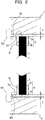
FIG. 2 is an explanatory diagram illustrating an end of a linear carbon material (CNT) in an enlarged manner; -
FIG. 3 is a graph illustrating dependency of a thermal resistance of a heat dissipation sheet on a thickness of an adhesive resin layer; -
FIG. 4 is an explanatory diagram illustrating a step of forming a plurality of linear carbon materials over a first substrate; -
FIG. 5 is an explanatory diagram illustrating a state in which a transfer member is pressed against a second end of each of the plurality of linear carbon materials; -
FIGs. 6A and 6B are explanatory diagrams illustrating a step of transferring the plurality of linear carbon materials to the transfer member; -
FIG. 7 illustrates a state in which a first adhesive resin having a first adhesive surface where a first release sheet is disposed is fixed over a second substrate; -
FIG. 8 is an explanatory diagram illustrating a state in which a first end surface formed at a first end of each of the plurality of linear carbon materials transferred to the transfer member is brought into contact with the first adhesive resin having the first adhesive surface where the first release sheet is disposed; -
FIG. 9 is an explanatory diagram illustrating a state in which the second substrate is mounted over a hot plate; -
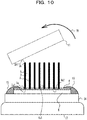
FIG. 10 is an explanatory diagram illustrating a state in which the transfer member is removed from the second end and the plurality of linear carbon materials are transferred to the first adhesive resin; -
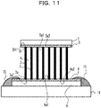
FIG. 11 is an explanatory diagram illustrating a state in which a second adhesive resin having a second adhesive surface where a second release sheet is disposed is brought into contact with a second end surface formed at a second end of each of the plurality of linear carbon materials; -
FIG. 12 is an explanatory diagram illustrating a state in which the second substrate is mounted over the hot plate and the first release sheet and the second release sheet are pressed against each other; -
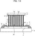
FIG. 13 is an explanatory diagram illustrating a state in which the first end of each linear carbon material enters the first adhesive resin and the second end of each linear carbon material enters the second adhesive resin; -
FIG. 14 is an explanatory diagram illustrating a state in which the second substrate is mounted over the hot plate, and the first release sheet and the second release sheet are pressed against each other to adjust a distance between the first end surface and the first adhesive surface and a distance between the second end surface and the second adhesive surface; -
FIG. 15 is a photograph illustrating an adhesive resin layer in a case where the first release sheet and the second release sheet are pressed against each other at an appropriate temperature; -
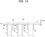
FIG. 16 is an explanatory diagram schematically illustrating a state illustrated inFIG. 15 ; -
FIG. 17 is a photograph illustrating an adhesive resin layer in a case where the first release sheet and the second release sheet are pressed against each other at a temperature lower than the appropriate temperature; -
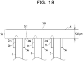
FIG. 18 is an explanatory diagram schematically illustrating a state illustrated inFIG. 17 ; -
FIG. 19 is a photograph illustrating an adhesive resin layer in a case where the first release sheet and the second release sheet are pressed against each other at a temperature higher than the appropriate temperature; -
FIG. 20 is an explanatory diagram schematically illustrating a state illustrated inFIG. 19 ; and -
FIG. 21 is an explanatory diagram illustrating a use state of the heat dissipation sheet of the embodiment. - A heat dissipation sheet is demanded to have favorable thermal conductivity between a heating element such as a semiconductor chip and a heat dissipation element such as a heat spreader, and have adhesiveness for fixing the heat dissipation element to the heating element. The transfer sheet disclosed in International Publication Pamphlet No.
WO 2018/110255 has room for improvement in terms of achieving both favorable thermal conductivity and adhesiveness. - Hereinafter, an embodiment of a technique for ensuring adhesiveness to a heating element and a heat dissipation element and thermal conductivity between the heating element and the heat dissipation element will be described with reference to the accompanying drawings. In the drawings, the dimensions, ratios, or the like of parts are occasionally not illustrated to be completely consistent with those of the actual parts. In some drawings, for convenience of description, elements actually present are omitted or the elements are exaggerated in dimensions compared to the actual elements.
- A
heat dissipation sheet 100 of an embodiment will be described with reference toFIGs. 1 to 3 . Theheat dissipation sheet 100 includes a heatdissipation sheet body 1, afirst release sheet 6 provided on one surface side of the heatdissipation sheet body 1, and asecond release sheet 7 provided on the other surface side of the heatdissipation sheet body 1. Theheat dissipation sheet 100 is disposed between a heating element 31 (refer toFIG. 21 ) represented by an electronic component that generates heat, such as a central processing unit (CPU), and a heat dissipation element 32 (refer toFIG. 21 ) represented by a heat spreader, joins theheating element 31 and theheat dissipation element 32, and conducts heat between theheating element 31 and theheat dissipation element 32. A method for using theheat dissipation sheet 100 will be described later. - The heat
dissipation sheet body 1 includes a carbon nanotube layer (hereinafter referred to as a "CNT layer") 2 as a carbon material layer. TheCNT layer 2 is formed by gathering a plurality of carbon nanotubes (hereinafter referred to as "CNTs") 3 as a plurality of linear carbon materials into a sheet shape. Since the plurality ofCNTs 3 extend substantially in the same direction, the CNT layer may be formed by planarly spreading the plurality ofCNTs 3 in a sheet shape. The CNT 3 may be a single layer or a multilayer. The surface density of theCNTs 3 is 1×10¹⁰ pieces/cm2 or more. This is in consideration of heat dissipation and electrical conductivity. In particular, the surface density of theCNTs 3, for example, the number ofCNTs 3 depends on the amount of paths for heat dissipation and electrical conduction, and as the number ofCNTs 3 is increased, the heat dissipation and electrical conductivity become more dominant. Theheat dissipation sheet 100 of the present embodiment is used for heat conduction between theheating element 31 and theheat dissipation element 32, but by setting the surface density of theCNTs 3 to be 1×10¹⁰ pieces/cm2 or more, characteristics suitable for this use may be provided. - In each drawing, the interval between the
CNTs 3 is drawn to be substantially uniform, but in reality, since theCNTs 3 grow randomly, the distance between theadjacent CNTs 3 may not be uniform. - The length of each
CNT 3 is substantially equal to the thickness tc of theCNT layer 2. The thickness tc may be appropriately set according to the use of theheat dissipation sheet 100, and may be set in a range of approximately 100 µm to 500 µm. - In the
CNT layer 2, agap 8 is formed between theadjacent CNTs 3. This improves the contractility of theCNT layer 2. For example, theCNT layer 2 easily follows the expansion and contraction of theheat dissipation sheet 1 caused by a thermal cycle in which the rise and fall of the temperature are repeated. - Each
linear CNT 3 has afirst end 3a, and asecond end 3b located on a side opposite to thefirst end 3a. A first end surface 3a1 is formed at thefirst end 3a, and a second end surface 3b1 is formed at thesecond end 3b. - Referring to
FIG. 2 , a firstadhesive resin 4 is provided on thefirst end 3a side. The firstadhesive resin 4 may be an epoxy resin. The firstadhesive resin 4 includes a firstadhesive resin layer 4a, and an embeddedportion 4b continuous with the firstadhesive resin layer 4a. The firstadhesive resin layer 4a has a first surface, and a second surface on a side opposite to the first surface. The first surface is a first holding surface 4a1 for holding eachCNT 3, and the embeddedportion 4b is provided at the first holding surface 4a1. Thefirst end 3a (first end surface 3a1) of eachCNT 3 is in contact with the first holding surface 4a1, and the embeddedportion 4b is provided around thefirst end 3a so that thefirst end 3a is embedded. In this manner, eachCNT 3 is held by the firstadhesive resin 4, and eachCNT 3 and the firstadhesive resin 4 are firmly integrated. The second surface of the firstadhesive resin layer 4a is a first adhesive surface 4a2. The first adhesive surface 4a2 is located on a side opposite to the embeddedportion 4b, and thefirst release sheet 6 is attached to the first adhesive surface 4a2 when theheat dissipation sheet 100 is in an unused state, for example, when theheat dissipation sheet 100 is for sale. Thefirst release sheet 6 is a film-like member, and is peeled off in the use state of theheat dissipation sheet 100, and the first adhesive surface 4a2 is bonded to theheating element 31 or the heat dissipation element 32 (refer toFIG. 21 ). - Referring to
FIG. 2 , a secondadhesive resin 5 is provided on thesecond end 3b side. As with the firstadhesive resin 4, the secondadhesive resin 5 may be an epoxy resin. The secondadhesive resin 5 includes a secondadhesive resin layer 5a, and an embeddedportion 5b continuous with the secondadhesive resin layer 5a. The secondadhesive resin layer 5a has a third surface, and a fourth surface on a side opposite to the third surface. The fourth surface is a second holding surface 5a1 for holding eachCNT 3, and the embeddedportion 5b is provided at the second holding surface 5a1. Thesecond end 3b (second end surface 3b1) of eachCNT 3 is in contact with the second holding surface 5a1, and the embeddedportion 5b is provided around thesecond end 3b so that thesecond end 3b is embedded. In this manner, eachCNT 3 is held by the secondadhesive resin 5, and eachCNT 3 and the secondadhesive resin 5 are firmly integrated. The third surface of the secondadhesive resin layer 5a is a second adhesive surface 5a2. The second adhesive surface 5a2 is located on a side opposite to the embeddedportion 5b, and thesecond release sheet 7 is attached to the second adhesive surface 5a2 when theheat dissipation sheet 100 is in an unused state, for example, when theheat dissipation sheet 100 is for sale. Thesecond release sheet 7 is a film-like member, and is peeled off in the use state of theheat dissipation sheet 100, and the second adhesive surface 5a2 is bonded to theheating element 31 or the heat dissipation element 32 (refer toFIG. 21 ). - The thickness S of the first
adhesive resin layer 4a is less than 1 µm. Since the firstadhesive resin layer 4a is present, the thickness S does not become 0 µm. A state in which the thickness S of the firstadhesive resin layer 4a is 0 µm means a state in which the first end surface 3a1 is exposed to the first adhesive surface 4a2. When the first end surface 3a1 is exposed to the first adhesive surface 4a2, the adhesiveness is affected. Therefore, it is not desirable that the first end surface 3a1 is exposed to the first adhesive surface 4a2. Thus, in the present embodiment, the thickness S of the firstadhesive resin layer 4a is made not to be 0 µm. - On the other hand, the thickness S of the first
adhesive resin layer 4a is preferably as thin as possible from the viewpoint of improving thermal conductivity. With reference toFIG. 3 , the dependency of the thermal resistance of theheat dissipation sheet 100 on the thickness of the adhesive resin layer will be described. Referring toFIG. 3 , it may be seen that the thermal resistance is increased as the thickness of the adhesive resin layer is increased. Therefore, the thickness S of the adhesive resin layer is desirably as thin as possible. Thus, in the present embodiment, the thickness S is less than 1 µm. The thickness S of the adhesive resin layer is preferably as thin as possible, and is preferably set in a range of 200 nm to 800 nm. The thickness S of the adhesive resin layer may also be referred to as a distance between the end surface of each CNT and the adhesive surface of the adhesive resin layer. - Similarly, the thickness S of the second
adhesive resin layer 5a is 1 µm, and the thickness S is made not to be 0 µm. Since the properties demanded for the secondadhesive resin layer 5a are the same as those of the firstadhesive resin layer 4a, detailed description thereof will be omitted. - In the present embodiment, the
CNT layer 2 using theCNTs 3 is provided. EachCNT 3 is a material having very high heat conductivity (1500 to 3000 W/m·K) as well as excellent flexibility and heat resistance, and has properties suitable for a heat dissipation material. In the present embodiment, high thermal conductivity is achieved by adopting such aCNT 3 and setting the thickness S of each of the firstadhesive resin layer 4a and the secondadhesive resin layer 5a to be less than 1 µm. Since the first end surface 3a1 of theCNT 3 is not exposed to the first adhesive surface 4a2 and similarly, the second end surface 3b1 is not exposed to the second adhesive surface 5a2, the adhesiveness of each adhesive surface is ensured. - Referring to
FIGs. 4 to 14 , an example of a method for manufacturing theheat dissipation sheet 100 of the embodiment will be described. - As illustrated in
FIG. 4 , a plurality ofCNTs 3 are formed over afirst substrate 10. EachCNT 3 has thefirst end 3a on thefirst substrate 10 side and thesecond end 3b on the opposite side. In the present embodiment, a silicon substrate is used as thefirst substrate 10. As thefirst substrate 10, a semiconductor substrate such as a silicon substrate, an alumina (sapphire) substrate, a magnesium oxide (MgO) substrate, a glass substrate, a metal substrate such as a stainless steel substrate, stainless steel foil, aluminum foil, or the like may be used. A thin film may be formed over the substrate. For example, a silicon substrate over which a silicon oxide film having a film thickness of about 300 nm is formed may be used. Thefirst substrate 10 is peeled off after theCNT 3 is formed. For this purpose, it is desirable that thefirst substrate 10 does not change in quality at the formation temperature of theCNT 3, and at least the surface of thefirst substrate 10 which is in contact with thefirst end 3a of theCNT 3 is made of a material that may be easily peeled off from theCNT 3. Alternatively, thefirst substrate 10 may be made of a material that may be selectively etched with respect to theCNT 3. - On the
first substrate 10, by sputtering, an Al (aluminum) film having a film thickness of 1.0 nm is formed and a Fe (iron) film having a film thickness of 2.5 nm is formed, thereby forming a catalyst metal film made of Fe on the Al film as a base. Methods other than sputtering may be adopted, and the film thickness is not limited to 2.5 mm. In addition to Fe, Co (cobalt), Ni (nickel), Au (gold), Ag (silver), Pt (platinum), or an alloy containing at least one of these materials may be used as the catalyst metal. As the catalyst, in addition to the metal film, metal fine particles prepared by controlling the size in advance using a differential mobility analyzer (DMA) or the like may be used. Also in this case, the metal species may be the same as that of the thin film. As a base film of these catalyst metals, a film formed of Mo (molybdenum), Ti (titanium), Hf (hafnium), Zr (zirconium), Nb (niobium), V (vanadium), TaN (tantalum nitride), TiSix (titanium silicide), Al, Al2O3 (aluminum oxide), TiOx (titanium oxide), Ta (tantalum), W (tungsten), Cu (copper), Au (gold), Pt (platinum), Pd (palladium), or TiN (titanium nitride), or a film formed of an alloy containing at least one of these materials may be formed. For example, a laminated structure of Fe (2.5 nm)/AI (10 nm), a laminated structure of Co (2.6 nm)/TiN (5 nm), or the like may be applied. In a case of using metal fine particles, for example, a laminated structure of Co (average diameter 3.8 nm)/TiN (5 nm) may be applied. - Next, the
CNT 3 is grown over the substrate by, for example, hot filament CVD using the catalyst metal film as the catalyst. The growth conditions for theCNT 3 are that, for example, a mixed gas of acetylene and argon (partial pressure ratio 1:9) is used as a source gas, the total gas pressure in a film forming chamber is 1 kPa, the hot filament temperature is 1000°C, and the growth time is 20 minutes. In this manner,multi-layered CNTs 3 having 3 to 6 layers (about 4 layers on average), a diameter of 4 to 8 nm (6 nm on average), and a length of 80 µm (growth rate: 4 µm/min) may be grown. TheCNT 3 may be formed by other methods for film formation such as thermal CVD or remote plasma CVD. TheCNT 3 to be grown may be a single layer. In addition to acetylene, hydrocarbons such as methane and ethylene, alcohols such as ethanol and methanol, and the like may be used as the carbon raw material. - In this manner, a plurality of carbon nanotubes oriented substantially perpendicular to the surface of the
first substrate 10 are formed over a region of thefirst substrate 10 where the catalyst metal film is formed. Under the above-described growth conditions, the surface density of theCNTs 3 was about 1×10¹⁰ pieces/cm2. Thegap 8 was formed between theadjacent CNTs 3. - A portion apart from the
first substrate 10 is thesecond end 3b, and a tip portion thereof is the second end surface 3b1. Due to the growth mechanism of theCNTs 3, the tip ends of theCNTs 3 may be mixed in the lateral direction, and in this case, a portion farthest from thefirst substrate 10 is defined as the second end surface 3b1. - Referring to
FIG. 5 , atransfer member 11 is brought into contact with the second end surface 3b1 of eachsecond end 3b of theCNTs 3 grown over thefirst substrate 10, and is pressed toward thefirst substrate 10 as indicated byarrows 12. Thetransfer member 11 in the present embodiment is a silicone rubber sheet, but other materials such as natural rubbers and synthetic rubbers may be used as the transfer member as long as the material may transfer theCNTs 3. - After the
transfer member 11 is pressed against theCNTs 3, when thetransfer member 11 is peeled off as indicated by anarrow 13 inFIG. 6A , theCNTs 3 are transferred to thetransfer member 11 as illustrated inFIG. 6B . - Referring to
FIG. 7 , the firstadhesive resin 4, which is an epoxy resin, is provided over asecond substrate 14. Thesecond substrate 14 is a silicon substrate. Thefirst release sheet 6 is disposed over the first adhesive surface 4a2 of the firstadhesive resin 4. The firstadhesive resin 4 is disposed such that thefirst release sheet 6 is brought into contact with thesecond substrate 14 and the firstadhesive resin 4 is located on the upper side. The firstadhesive resin 4 is fixed over thesecond substrate 14 with a heat-resistant tape 15. - Referring to
FIG. 8 , theCNTs 3 transferred to thetransfer member 11 are disposed over the firstadhesive resin 4, and are pressed toward thesecond substrate 14 as indicated by arrows 16. In this manner, the first end surface 3a1 of eachfirst end 3a is brought into close contact with the firstadhesive resin 4. - Thereafter, as illustrated in
FIG. 9 , thesecond substrate 14 is mounted over ahot plate 17. Thesecond substrate 14 is heated by thehot plate 17. When thesecond substrate 14 is heated, the firstadhesive resin 4 is softened. The temperature of thehot plate 17 is adjusted such that the firstadhesive resin 4 is softened to be in a low viscosity state. When the firstadhesive resin 4 is softened to be in a low viscosity state, the adhesion of the firstadhesive resin 4 is increased. In this state, when thetransfer member 11 is pressed toward thesecond substrate 14 as indicated byarrows 18, thefirst end 3a of eachCNT 3 is held by the firstadhesive resin 4. - The heat of the
hot plate 17 is also transferred to thetransfer member 11 through the firstadhesive resin 4 and theCNTs 3. In this manner, thetransfer member 11 is softened and thetransfer member 11 may be removed from the second ends 3b of theCNTs 3. As illustrated inFIG. 10 , when thetransfer member 11 is removed as indicated by anarrow 19, the plurality ofCNTs 3 may be transferred to the firstadhesive resin 4. - Referring to
FIG. 11 , the secondadhesive resin 5 having the second adhesive surface 5a2 where thesecond release sheet 7 is disposed over the second end surface 3b1 formed at thesecond end 3b of eachCNT 3. - As illustrated in
FIG. 12 , thesecond substrate 14 is heated over thehot plate 17. The temperature at this time is the same as the temperature when thesecond substrate 14 is heated inFIGs. 8 to 10 . The heat of thehot plate 17 is also transferred to the secondadhesive resin 5 through the firstadhesive resin 4 and theCNTs 3. In this manner, the secondadhesive resin 5 is softened. When the secondadhesive resin 5 is softened to be in a low viscosity state, the adhesion of the secondadhesive resin 5 is increased. In this state, when the secondadhesive resin 5 is pressed toward thesecond substrate 14 as indicated by arrows 20, thesecond end 3b of eachCNT 3 is held by the secondadhesive resin 5. - Then, as illustrated in
FIG. 13 , first, thesecond substrate 14 is taken off of thehot plate 17, and is cooled. At this time, thefirst end 3a of theCNT 3 is held by the firstadhesive resin 4, and thesecond end 3b of theCNT 3 is held by the secondadhesive resin 5. - Thereafter, as illustrated in
FIG. 14 , thesecond substrate 14 is mounted over thehot plate 17 again, and thesecond substrate 14 is heated. Although the heat of thehot plate 17 is also transferred to the firstadhesive resin 4 and the secondadhesive resin 5, the temperature of each of the firstadhesive resin 4 and the secondadhesive resin 5 is set to be higher than that when thesecond substrate 14 is heated inFIGs. 8 to 10 ,12 , and13 . Thehot plate 17 may be provided over thesecond release sheet 7. - In this manner, the first
adhesive resin layer 4a is formed between the first end surface 3a1 and the first adhesive surface 4a2 by adjusting the distance between the first end surface 3a1 and the first adhesive surface 4a2 while adjusting the temperature of the firstadhesive resin 4. The secondadhesive resin layer 5a is formed between the second end surface 3b1 and the second adhesive surface 5a2 by adjusting the distance between the second end surface 3b1 and the second adhesive surface 5a2 while adjusting the temperature of the secondadhesive resin 5. - The temperature of each of the first
adhesive resin 4 and the secondadhesive resin 5 is adjusted because the distance between the first end surface 3a1 and the first adhesive surface 4a2 and the distance between the second end surface 3b1 and the second adhesive surface 5a2 have a correlation with the temperature. - Referring to
FIGs. 15 and16 , when the secondadhesive resin 5 is heated to an appropriate temperature and is pressed as indicated by arrows 21 inFIG. 14 , a secondadhesive resin layer 5a having a thickness S of less than 1 µm is formed. In accordance with this, the second adhesive resin enters between theCNTs 3 by capillary phenomenon to form the embeddedportion 5b continuous with the secondadhesive resin layer 5a, and thesecond end 3b of theCNT 3 is embedded and fixed in the embeddedportion 5b. It is considered that the thickness S may be set to be less than 1 µm because the secondadhesive resin 5 is heated to an appropriate temperature and is appropriately softened to have a low viscosity, so that thesecond end 3b of theCNT 3 is appropriately inserted into the softened secondadhesive resin 5. - Although the second
adhesive resin 5 is illustrated inFIGs. 15 and16 for convenience of description, the same phenomenon occurs in the firstadhesive resin 4 so that the firstadhesive resin layer 4a is formed and the embeddedportion 4b is formed. Thefirst end 3a is embedded and fixed in the embeddedportion 4b. - On the other hand, referring to
FIGs. 17 and18 , when the secondadhesive resin 5 is heated to a temperature lower than the appropriate temperature and is pressed as indicated by arrows 21 inFIG. 14 , the thickness S becomes 1 µm or more. It is considered that this is because when the temperature of the secondadhesive resin 5 is low, the secondadhesive resin 5 is not easily softened, and thesecond end 3b of theCNT 3 is not inserted into an appropriate position of the secondadhesive resin 5 even when being pressed. The same applies to the firstadhesive resin 4. - Referring to
FIGs. 19 and20 , when the secondadhesive resin 5 is heated to a temperature higher than the appropriate temperature and is pressed as indicated by arrows 21 inFIG. 14 , aggregation occurs on the second end surface 3b1 side to form a gap on the second adhesive surface. For example, the thickness S of the adhesive surface approaches 0. As a result, the secondadhesive resin layer 5a is not appropriately formed. When the second end surface 3b1 is exposed to the second adhesive surface 5a2 in this manner, the adhesiveness of the second adhesive surface 5a2 may be impaired. The same applies to the firstadhesive resin 4. - In this manner, the first
adhesive resin layer 4a and the secondadhesive resin layer 5a each of which the thickness S is less than 1 µm may be formed by pressing the firstadhesive resin 4 and the secondadhesive resin 5 while adjusting the temperature of each of the firstadhesive resin 4 and the secondadhesive resin 5. It is possible to realize favorable thermal conductivity of theheat dissipation sheet 100 by setting the thickness S of each of the firstadhesive resin layer 4a and the secondadhesive resin layer 5a to be less than 1 µm. - When the heat-
resistant tape 15 is removed after the step illustrated inFIG. 14 is performed, theheat dissipation sheet 100 of the present embodiment illustrated inFIG. 1 may be obtained. - Referring to
FIG. 21 , the use state of theheat dissipation sheet 100 of the embodiment will be described. When theheat dissipation sheet 100 is used, thefirst release sheet 6 and thesecond release sheet 7 are removed, and the heatdissipation sheet body 1 is disposed between theheating element 31 and theheat dissipation element 32 and is bonded therewith. For example, a user peels off one of thefirst release sheet 6 and thesecond release sheet 7, temporarily bonds the heatdissipation sheet body 1 to theheat dissipation element 32, peels off the other release sheet, fits the heatdissipation sheet body 1 to theheating element 31, and performs thermocompression bonding. In this manner, theheat dissipation element 32 may be fixed to theheating element 31. The thickness S of the adhesive resin layer after the thermocompression bonding is preferably 30 nm or less. As described above, according to the present embodiment, the work of mounting theheat dissipation element 32 is easy and the heat dissipation sheet has excellent handleability and may be cut, the heat dissipation sheet may cope with the size and shape of the adherent, and may satisfy the demanded thermal conductivity, followability to a heat cycle, and heat resistance. - Although the preferred embodiments of the present disclosure have been described in detail above, the present disclosure is not limited to the particular embodiments, and various modifications and changes may be made within the scope of the gist of the present disclosure described in the claims.
Claims (12)
- A heat dissipation sheet comprising:a carbon material layer configured to include a plurality of linear carbon materials arranged in parallel with each other;an adhesive resin layer configured to include a first surface to be in contact with an end of each of the plurality of linear carbon materials, a thickness of the adhesive resin layer being less than 1 µm; anda release sheet configured to be in contact with a second surface among a plurality of surfaces of the adhesive resin layer, the second surface being over a side opposite to the first surface.
- The heat dissipation sheet according to claim 1,
wherein the thickness of the adhesive resin layer is 200 nm to 800 nm. - The heat dissipation sheet according to claim 1 or claim 2,
wherein the carbon material layer includes a gap provided between the plurality of linear carbon materials. - The heat dissipation sheet according to any one of claim 1 to claim 3,
wherein the plurality of linear carbon materials are provided with a surface density of 1×10¹⁰ pieces/cm2 or more. - The heat dissipation sheet according to any one of claim 1 to claim 4,
wherein the end of each of the plurality of linear carbon materials is embedded continuously with the adhesive resin layer. - A method of manufacturing a heat dissipation sheet, the method comprising:generating, over a substrate, a plurality of linear carbon materials each configured to include a first end that faces the substrate;transferring the plurality of linear carbon materials to a transfer member by bringing a second end of each of the plurality of linear carbon materials into contact with the transfer member, the second end being over a side opposite to the first end;transferring the plurality of linear carbon materials to a first adhesive resin by bringing the first end of each of the plurality of linear carbon materials transferred to the transfer member into contact with a first surface of the first adhesive resin that includes a second surface over which a first release sheet is disposed, the first surface being over a side opposite to the second surface, and by removing the transfer member from the second end; anddisposing the second end by bringing the second end into contact with a fourth surface of a second adhesive resin that includes a third surface over which a second release sheet is disposed, the fourth surface being over a side opposite to the third surface.
- The method according to claim 6,
wherein a thickness of an adhesive resin layer to be in contact with an end of each of the plurality of linear carbon materials is 200 nm to 800 nm. - The method according to claim 6 or claim 7,
wherein a gap is provided between the plurality of linear carbon materials. - The method according to any one of claim 6 to claim 8,
wherein the plurality of linear carbon materials are provided with a surface density of 1×10¹⁰ pieces/cm2 or more. - The method according to any one of claim 6 to claim 9,
wherein the first end is embedded in the first adhesive resin, and
wherein the second end is embedded in the second adhesive resin. - The method according to any one of claim 6 to claim 10,
wherein adjusting a distance between a first end surface of the first end and the first surface to form a first adhesive resin layer between the first end surface and the first surface and adjusting a distance between a second end surface of the second end and the second surface to form a second adhesive resin layer between the second end surface and the second surface are both performed while adjusting a temperature of each of the first adhesive resin and the second adhesive resin. - A heat dissipation sheet comprising:a heat dissipation sheet body;a first release sheet provided on a first surface of the heat dissipation sheet body;a second release sheet provided on a second surface of the heat dissipation sheet body;a carbon nanotube layer included within the heat dissipation sheet body, the carbon nanotube layer including a plurality of linear carbon materials arranged in parallel with each other; andan adhesive resin layer configured to include a first surface in contact with an end of each of the plurality of linear carbon materials and have a thickness of less than 1 µm.
Applications Claiming Priority (1)
| Application Number | Priority Date | Filing Date | Title |
|---|---|---|---|
| JP2019220613A JP7348515B2 (en) | 2019-12-05 | 2019-12-05 | Heat dissipation sheet and method for manufacturing heat dissipation sheet |
Publications (2)
| Publication Number | Publication Date |
|---|---|
| EP3831595A1 true EP3831595A1 (en) | 2021-06-09 |
| EP3831595B1 EP3831595B1 (en) | 2025-12-31 |
Family
ID=73455594
Family Applications (1)
| Application Number | Title | Priority Date | Filing Date |
|---|---|---|---|
| EP20208044.6A Active EP3831595B1 (en) | 2019-12-05 | 2020-11-17 | HEAT DISPENSING LAYER AND METHOD FOR PRODUCING A HEAT DISPENSING LAYER |
Country Status (5)
| Country | Link |
|---|---|
| US (2) | US12194724B2 (en) |
| EP (1) | EP3831595B1 (en) |
| JP (1) | JP7348515B2 (en) |
| CN (1) | CN112930076B (en) |
| TW (1) | TWI742919B (en) |
Families Citing this family (2)
| Publication number | Priority date | Publication date | Assignee | Title |
|---|---|---|---|---|
| JP7348515B2 (en) * | 2019-12-05 | 2023-09-21 | 富士通株式会社 | Heat dissipation sheet and method for manufacturing heat dissipation sheet |
| JP2023174240A (en) * | 2022-05-27 | 2023-12-07 | 新光電気工業株式会社 | substrate |
Citations (4)
| Publication number | Priority date | Publication date | Assignee | Title |
|---|---|---|---|---|
| US20100172101A1 (en) * | 2009-01-07 | 2010-07-08 | Tsinghua University | Thermal interface material and method for manufacturing the same |
| US20110030938A1 (en) * | 2009-08-05 | 2011-02-10 | Tsinghua University | Heat dissipation structure and heat dissipation system adopting the same |
| EP2546871A1 (en) * | 2010-03-12 | 2013-01-16 | Fujitsu Limited | Heat dissipating structure and production method therefor |
| WO2018110255A1 (en) | 2016-12-15 | 2018-06-21 | Jnc株式会社 | Transfer sheet |
Family Cites Families (12)
| Publication number | Priority date | Publication date | Assignee | Title |
|---|---|---|---|---|
| JP4443746B2 (en) | 2000-09-13 | 2010-03-31 | ポリマテック株式会社 | Method for producing anisotropic heat transfer sheet |
| JP2010240871A (en) * | 2009-04-01 | 2010-10-28 | Nippon Valqua Ind Ltd | Transfer body and impregnation body, and method of manufacturing them |
| CN103205075B (en) * | 2012-01-17 | 2015-09-02 | 帛宏兴业股份有限公司 | Heat dissipation material, heat dissipation structure, preparation method and use thereof |
| KR101491053B1 (en) | 2012-03-06 | 2015-02-10 | 주식회사 아모그린텍 | pressure-sensitive adhesive tape and preparation method thereof |
| JP6354235B2 (en) * | 2014-03-20 | 2018-07-11 | 富士通株式会社 | Electronic device and assembly method thereof, and sheet-like structure and manufacturing method thereof |
| JP6398627B2 (en) * | 2014-11-10 | 2018-10-03 | 富士通株式会社 | Heat dissipation sheet, method for manufacturing heat dissipation sheet, and method for manufacturing electronic device |
| WO2017115832A1 (en) * | 2015-12-28 | 2017-07-06 | 日立造船株式会社 | Carbon nanotube composite material and method for producing carbon nanotube composite material |
| JP6720717B2 (en) * | 2016-06-20 | 2020-07-08 | 富士通株式会社 | Heat dissipation sheet manufacturing method |
| JP6711208B2 (en) | 2016-08-25 | 2020-06-17 | 富士通株式会社 | Electronic device and method of manufacturing electronic device |
| JP6810343B2 (en) * | 2016-10-17 | 2021-01-06 | 富士通株式会社 | Manufacturing method of carbon nanotube structure, heat dissipation sheet and carbon nanotube structure |
| JP6901896B2 (en) * | 2017-03-31 | 2021-07-14 | 日立造船株式会社 | Filler / resin composite, manufacturing method of filler / resin composite, filler / resin composite layer, and usage of filler / resin composite |
| JP7348515B2 (en) * | 2019-12-05 | 2023-09-21 | 富士通株式会社 | Heat dissipation sheet and method for manufacturing heat dissipation sheet |
-
2019
- 2019-12-05 JP JP2019220613A patent/JP7348515B2/en active Active
-
2020
- 2020-11-11 TW TW109139377A patent/TWI742919B/en active
- 2020-11-17 EP EP20208044.6A patent/EP3831595B1/en active Active
- 2020-11-19 US US16/952,130 patent/US12194724B2/en active Active
- 2020-11-30 CN CN202011373405.1A patent/CN112930076B/en active Active
-
2024
- 2024-12-04 US US18/967,740 patent/US20250196486A1/en active Pending
Patent Citations (4)
| Publication number | Priority date | Publication date | Assignee | Title |
|---|---|---|---|---|
| US20100172101A1 (en) * | 2009-01-07 | 2010-07-08 | Tsinghua University | Thermal interface material and method for manufacturing the same |
| US20110030938A1 (en) * | 2009-08-05 | 2011-02-10 | Tsinghua University | Heat dissipation structure and heat dissipation system adopting the same |
| EP2546871A1 (en) * | 2010-03-12 | 2013-01-16 | Fujitsu Limited | Heat dissipating structure and production method therefor |
| WO2018110255A1 (en) | 2016-12-15 | 2018-06-21 | Jnc株式会社 | Transfer sheet |
Also Published As
| Publication number | Publication date |
|---|---|
| TW202122554A (en) | 2021-06-16 |
| US20250196486A1 (en) | 2025-06-19 |
| TWI742919B (en) | 2021-10-11 |
| CN112930076A (en) | 2021-06-08 |
| JP7348515B2 (en) | 2023-09-21 |
| JP2021090014A (en) | 2021-06-10 |
| CN112930076B (en) | 2023-12-19 |
| EP3831595B1 (en) | 2025-12-31 |
| US12194724B2 (en) | 2025-01-14 |
| US20210172690A1 (en) | 2021-06-10 |
Similar Documents
| Publication | Publication Date | Title |
|---|---|---|
| US20250196486A1 (en) | Heat dissipation sheet and method of manufacturing heat dissipation sheet | |
| JP6135760B2 (en) | Heat dissipation structure, method for manufacturing the same, and electronic device | |
| EP2763167A1 (en) | Heat-dissipating material and method for producing same, and electronic device and method for producing same | |
| CN102792441B (en) | Radiator structure and manufacture method thereof | |
| US9105600B2 (en) | Sheet structure, method of manufacturing sheet structure, and electronic device | |
| TW201220445A (en) | Diamond particle mololayer heat spreaders and associated methods | |
| WO2019188614A1 (en) | Semiconductor package | |
| US20220139800A1 (en) | Heat dissipation sheet, manufacturing method of heat dissipation sheet, and electronic apparatus | |
| JP6244651B2 (en) | Sheet-like structure and manufacturing method thereof, and electronic device and manufacturing method thereof | |
| JP6223903B2 (en) | Carbon nanotube sheet, electronic device, method of manufacturing carbon nanotube sheet, and method of manufacturing electronic device | |
| JP6354235B2 (en) | Electronic device and assembly method thereof, and sheet-like structure and manufacturing method thereof | |
| JP6237231B2 (en) | Sheet-like structure and manufacturing method thereof, electronic component and assembly method thereof | |
| JP6065724B2 (en) | Sheet-like structure, electronic device, method for manufacturing sheet-like structure, and method for manufacturing electronic device | |
| JP6156057B2 (en) | Nanostructure sheet, electronic device, method for producing nanostructure sheet, and method for producing electronic device | |
| CN111146076B (en) | Preparation method for combining nano sintered copper and wafer and connection structure thereof | |
| JP5935302B2 (en) | Sheet-like structure, manufacturing method thereof, electronic device, and manufacturing method thereof | |
| JP5998557B2 (en) | Manufacturing method of heat dissipation sheet | |
| JP2018129482A (en) | Heat dissipation sheet, heat dissipation sheet manufacturing method, and electronic device | |
| JP6826289B2 (en) | Thermally conductive structure, its manufacturing method and electronic device | |
| JP7484471B2 (en) | Carbon nanotube sheet, electronic device, and method for producing the carbon nanotube sheet | |
| JP6056501B2 (en) | Manufacturing method of heat dissipation structure | |
| JP2010192662A (en) | Method of manufacturing heat radiation component | |
| JP2014204056A (en) | Heat dissipation structure and manufacturing method therefor and electronic apparatus |
Legal Events
| Date | Code | Title | Description |
|---|---|---|---|
| PUAI | Public reference made under article 153(3) epc to a published international application that has entered the european phase |
Free format text: ORIGINAL CODE: 0009012 |
|
| STAA | Information on the status of an ep patent application or granted ep patent |
Free format text: STATUS: THE APPLICATION HAS BEEN PUBLISHED |
|
| STAA | Information on the status of an ep patent application or granted ep patent |
Free format text: STATUS: REQUEST FOR EXAMINATION WAS MADE |
|
| AK | Designated contracting states |
Kind code of ref document: A1 Designated state(s): AL AT BE BG CH CY CZ DE DK EE ES FI FR GB GR HR HU IE IS IT LI LT LU LV MC MK MT NL NO PL PT RO RS SE SI SK SM TR |
|
| 17P | Request for examination filed |
Effective date: 20210527 |
|
| RBV | Designated contracting states (corrected) |
Designated state(s): AL AT BE BG CH CY CZ DE DK EE ES FI FR GB GR HR HU IE IS IT LI LT LU LV MC MK MT NL NO PL PT RO RS SE SI SK SM TR |
|
| STAA | Information on the status of an ep patent application or granted ep patent |
Free format text: STATUS: EXAMINATION IS IN PROGRESS |
|
| 17Q | First examination report despatched |
Effective date: 20230111 |
|
| GRAP | Despatch of communication of intention to grant a patent |
Free format text: ORIGINAL CODE: EPIDOSNIGR1 |
|
| STAA | Information on the status of an ep patent application or granted ep patent |
Free format text: STATUS: GRANT OF PATENT IS INTENDED |
|
| INTG | Intention to grant announced |
Effective date: 20250828 |
|
| GRAS | Grant fee paid |
Free format text: ORIGINAL CODE: EPIDOSNIGR3 |
|
| GRAA | (expected) grant |
Free format text: ORIGINAL CODE: 0009210 |
|
| STAA | Information on the status of an ep patent application or granted ep patent |
Free format text: STATUS: THE PATENT HAS BEEN GRANTED |
|
| AK | Designated contracting states |
Kind code of ref document: B1 Designated state(s): AL AT BE BG CH CY CZ DE DK EE ES FI FR GB GR HR HU IE IS IT LI LT LU LV MC MK MT NL NO PL PT RO RS SE SI SK SM TR |
|
| REG | Reference to a national code |
Ref country code: CH Ref legal event code: F10 Free format text: ST27 STATUS EVENT CODE: U-0-0-F10-F00 (AS PROVIDED BY THE NATIONAL OFFICE) Effective date: 20251231 Ref country code: GB Ref legal event code: FG4D |
|
| REG | Reference to a national code |
Ref country code: DE Ref legal event code: R096 Ref document number: 602020064692 Country of ref document: DE |
|
| REG | Reference to a national code |
Ref country code: IE Ref legal event code: FG4D |
|
| REG | Reference to a national code |
Ref country code: LT Ref legal event code: MG9D |
|
| PG25 | Lapsed in a contracting state [announced via postgrant information from national office to epo] |
Ref country code: NO Free format text: LAPSE BECAUSE OF FAILURE TO SUBMIT A TRANSLATION OF THE DESCRIPTION OR TO PAY THE FEE WITHIN THE PRESCRIBED TIME-LIMIT Effective date: 20260331 |
|
| PG25 | Lapsed in a contracting state [announced via postgrant information from national office to epo] |
Ref country code: FI Free format text: LAPSE BECAUSE OF FAILURE TO SUBMIT A TRANSLATION OF THE DESCRIPTION OR TO PAY THE FEE WITHIN THE PRESCRIBED TIME-LIMIT Effective date: 20251231 Ref country code: HR Free format text: LAPSE BECAUSE OF FAILURE TO SUBMIT A TRANSLATION OF THE DESCRIPTION OR TO PAY THE FEE WITHIN THE PRESCRIBED TIME-LIMIT Effective date: 20251231 |
|
| PG25 | Lapsed in a contracting state [announced via postgrant information from national office to epo] |
Ref country code: RS Free format text: LAPSE BECAUSE OF FAILURE TO SUBMIT A TRANSLATION OF THE DESCRIPTION OR TO PAY THE FEE WITHIN THE PRESCRIBED TIME-LIMIT Effective date: 20260331 |
|
| PG25 | Lapsed in a contracting state [announced via postgrant information from national office to epo] |
Ref country code: LV Free format text: LAPSE BECAUSE OF FAILURE TO SUBMIT A TRANSLATION OF THE DESCRIPTION OR TO PAY THE FEE WITHIN THE PRESCRIBED TIME-LIMIT Effective date: 20251231 |
|
| PG25 | Lapsed in a contracting state [announced via postgrant information from national office to epo] |
Ref country code: BG Free format text: LAPSE BECAUSE OF FAILURE TO SUBMIT A TRANSLATION OF THE DESCRIPTION OR TO PAY THE FEE WITHIN THE PRESCRIBED TIME-LIMIT Effective date: 20251231 |
|
| REG | Reference to a national code |
Ref country code: NL Ref legal event code: MP Effective date: 20251231 |