EP3831552A1 - End effector and end effector device - Google Patents
End effector and end effector device Download PDFInfo
- Publication number
- EP3831552A1 EP3831552A1 EP19867875.7A EP19867875A EP3831552A1 EP 3831552 A1 EP3831552 A1 EP 3831552A1 EP 19867875 A EP19867875 A EP 19867875A EP 3831552 A1 EP3831552 A1 EP 3831552A1
- Authority
- EP
- European Patent Office
- Prior art keywords
- grasped
- fitting
- fitting recess
- end effector
- fingers
- Prior art date
- Legal status (The legal status is an assumption and is not a legal conclusion. Google has not performed a legal analysis and makes no representation as to the accuracy of the status listed.)
- Granted
Links
Images





Classifications
-
- B—PERFORMING OPERATIONS; TRANSPORTING
- B25—HAND TOOLS; PORTABLE POWER-DRIVEN TOOLS; MANIPULATORS
- B25J—MANIPULATORS; CHAMBERS PROVIDED WITH MANIPULATION DEVICES
- B25J15/00—Gripping heads and other end effectors
- B25J15/08—Gripping heads and other end effectors having finger members
-
- B—PERFORMING OPERATIONS; TRANSPORTING
- B25—HAND TOOLS; PORTABLE POWER-DRIVEN TOOLS; MANIPULATORS
- B25J—MANIPULATORS; CHAMBERS PROVIDED WITH MANIPULATION DEVICES
- B25J13/00—Controls for manipulators
- B25J13/08—Controls for manipulators by means of sensing devices, e.g. viewing or touching devices
- B25J13/081—Touching devices, e.g. pressure-sensitive
- B25J13/082—Grasping-force detectors
-
- B—PERFORMING OPERATIONS; TRANSPORTING
- B25—HAND TOOLS; PORTABLE POWER-DRIVEN TOOLS; MANIPULATORS
- B25J—MANIPULATORS; CHAMBERS PROVIDED WITH MANIPULATION DEVICES
- B25J13/00—Controls for manipulators
- B25J13/08—Controls for manipulators by means of sensing devices, e.g. viewing or touching devices
- B25J13/081—Touching devices, e.g. pressure-sensitive
- B25J13/084—Tactile sensors
-
- B—PERFORMING OPERATIONS; TRANSPORTING
- B25—HAND TOOLS; PORTABLE POWER-DRIVEN TOOLS; MANIPULATORS
- B25J—MANIPULATORS; CHAMBERS PROVIDED WITH MANIPULATION DEVICES
- B25J13/00—Controls for manipulators
- B25J13/08—Controls for manipulators by means of sensing devices, e.g. viewing or touching devices
- B25J13/088—Controls for manipulators by means of sensing devices, e.g. viewing or touching devices with position, velocity or acceleration sensors
-
- B—PERFORMING OPERATIONS; TRANSPORTING
- B25—HAND TOOLS; PORTABLE POWER-DRIVEN TOOLS; MANIPULATORS
- B25J—MANIPULATORS; CHAMBERS PROVIDED WITH MANIPULATION DEVICES
- B25J15/00—Gripping heads and other end effectors
- B25J15/02—Gripping heads and other end effectors servo-actuated
- B25J15/0253—Gripping heads and other end effectors servo-actuated comprising parallel grippers
-
- B—PERFORMING OPERATIONS; TRANSPORTING
- B25—HAND TOOLS; PORTABLE POWER-DRIVEN TOOLS; MANIPULATORS
- B25J—MANIPULATORS; CHAMBERS PROVIDED WITH MANIPULATION DEVICES
- B25J9/00—Program-controlled manipulators
- B25J9/16—Program controls
- B25J9/1679—Program controls characterised by the tasks executed
- B25J9/1687—Assembly, peg and hole, palletising, straight line, weaving pattern movement
-
- G—PHYSICS
- G05—CONTROLLING; REGULATING
- G05B—CONTROL OR REGULATING SYSTEMS IN GENERAL; FUNCTIONAL ELEMENTS OF SUCH SYSTEMS; MONITORING OR TESTING ARRANGEMENTS FOR SUCH SYSTEMS OR ELEMENTS
- G05B2219/00—Program-control systems
- G05B2219/30—Nc systems
- G05B2219/39—Robotics, robotics to robotics hand
- G05B2219/39532—Gripping force sensor build into finger
-
- G—PHYSICS
- G05—CONTROLLING; REGULATING
- G05B—CONTROL OR REGULATING SYSTEMS IN GENERAL; FUNCTIONAL ELEMENTS OF SUCH SYSTEMS; MONITORING OR TESTING ARRANGEMENTS FOR SUCH SYSTEMS OR ELEMENTS
- G05B2219/00—Program-control systems
- G05B2219/30—Nc systems
- G05B2219/40—Robotics, robotics mapping to robotics vision
- G05B2219/40032—Peg and hole insertion, mating and joining, remote center compliance
-
- G—PHYSICS
- G05—CONTROLLING; REGULATING
- G05B—CONTROL OR REGULATING SYSTEMS IN GENERAL; FUNCTIONAL ELEMENTS OF SUCH SYSTEMS; MONITORING OR TESTING ARRANGEMENTS FOR SUCH SYSTEMS OR ELEMENTS
- G05B2219/00—Program-control systems
- G05B2219/30—Nc systems
- G05B2219/40—Robotics, robotics mapping to robotics vision
- G05B2219/40625—Tactile sensor
Definitions
- the present disclosure relates to an end effector including a tactile sensor unit, and to an end effector device including the end effector.
- Patent Literature 1 discloses a robot control device including a force sense measuring device that acquires information on force sense acting on an object being grasped by a robot hand.
- This force sense measuring device is composed of a force sensor, and is provided at a portion of the robot hand that contacts with an object being grasped.
- the robot hand When it is attempted to fit an object being grasped into a recess of an object to be assembled while grasping the object being grasped by the robot hand using the robot control device, the robot hand may contacts with the edge of the opening of the recess in the middle of fitting the object being grasped into the recess. In this case, in order to fit the object being grasped into the recess, it is necessary to rotate the robot hand by about 90 degrees and press the object being grasped with a portion where the force sense measuring device is provided. Thus, the structure and control of the robot hand may be complicated.
- the present disclosure provides an end effector including a tactile sensor unit capable of fitting an object being grasped into a fitting recess of an object to be assembled with a simple configuration, and an end effector device including the end effector.
- the end effector includes a force receiving portion that is connected to the second end portion of each finger via the tactile sensor unit.
- the force receiving portion receives a force from the object being grasped when the object being grasped is grasped by the plurality of fingers.
- the force receiving portion includes a grasping surface and a pressing surface. The grasping surface is placed facing the object being grasped in a direction intersecting the extending direction to be able to grasp the object being grasped.
- the pressing surface is placed further away from the palm than the second end portion of each of the plurality of fingers and that extends in a direction intersecting the grasping surface.
- the object being grasped is grasped by the grasping surface of the force receiving portion and moved to the fitting recess of the object to be assembled and, then, the object being grasped is pressed against the object to be assembled with the pressing surface of the force receiving portion, so that the object being grasped is fitted into the fitting recess. That is, it is possible to realize an end effector including a tactile sensor unit capable of fitting the object being grasped into the fitting recess of the object to be assembled with a simple configuration.
- the end effector device it is possible to realize an end effector device capable of fitting an object being grasped into a fitting recess of an object to be assembled with a simple configuration by the end effector.
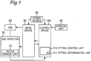
- An end effector 10 of the first embodiment of the present disclosure constitutes a part of an end effector device 1 such as a manipulator, for example, as shown in Fig. 1 .
- the end effector device 1 includes an end effector 10, an arm 20 connected to the end effector 10, a drive device 30 that drives the end effector 10 and the arm 20, a control device 100 that controls the drive device 30, an operation unit 40 connected to the control device 100, and a power source 50 that supplies power to the drive device 30 and the control device 100.
- the control device 100 controls drive of the end effector 10 and the arm 20 by outputting a command to the drive device 30 based on operation received by the operation unit 40.
- the arm 20 is connected to a palm 11 described later of the end effector 10, and can move so as to be able to arbitrarily change a position and posture of the end effector 10 by the drive device 30.
- the drive device 30 has a motor (not shown) that drives the palm 11 and each finger 12, and an encoder (not shown) that detects the rotation of the motor, and is configured to output information detected by the encoder to the control device 100.
- the end effector 10 includes the palm 11, a plurality of fingers 12 (two fingers 12 in the first embodiment) connected to the palm 11, and a tactile sensor unit 13 and a force-receiving portion 14 provided at each finger 12.
- Each finger 12 has a first end portion 121 provided with one end of each finger 12 in an extending direction of the finger 12.
- the first end portion 121 is connected to the palm 11.
- Each finger 12 is configured capable of grasping operation in which each finger 12 moves in a direction intersecting the extending direction thereof as well as approaching each other and grasps an object being grasped 60.
- each finger 12 has a substantially rectangular plate shape having substantially the same length in the extending direction thereof.
- Each finger 12 is placed side by side and substantially in parallel with another finger 12 so that their plate surfaces face each other.
- Each finger 12 is configured to be movable in a direction orthogonal to the plate surface by the drive device 30.
- the motor that drives each finger 12 may be configured by, for example, a linear motor.
- Tactile sensor unit 13 for example, is configured of a capacitance type or resistance type planar tactile sensor. Tactile sensor unit 13 is provided at a second end portion 122, which is a tip portion provided with the other end of each finger 12 in the extending direction thereof, in a state capable of detecting an external force from the object being grasped 60.
- each tactile sensor unit 13 is configured to be able to detect an external force in at least three axial directions by detecting a minute displacement/deformation as an electrical change, the minute displacement/deformation being caused by force that each force-receiving portion 14 receives from the object being grasped 60.
- tactile sensor unit 13 is configured to be able to detect at least a force in a Z direction along the extending direction of each finger 12, a force in a Y direction orthogonal to the Z direction and directed from one finger 12 to the other finger 12, and a force in a X direction (that is, the paper penetration direction in Fig. 2 ) orthogonal to the Z direction and the Y direction.
- Each force-receiving portion 14 is configured of metal, as an example. Each force-receiving portion 14 is connected to the second end portion 122 of each of the plurality of fingers 12 via the tactile sensor unit 13. Each force-receiving portion 14 is configured to receive a force from the object being grasped 60 when the object being grasped 60 is grasped by the plurality of fingers 12.
- each force-receiving portion 14 includes a first plate member 141 extending in the extending direction of each finger 12 and a second plate member 142 extending in a direction intersecting (for example, orthogonal to) the first plate member 141 as well as being away from each other.
- the first plate member 141 has a grasping surface 15.
- the grasping surface 15 is placed facing the object being grasped 60 in a direction intersecting the extending direction of each finger 12 to be able to grasp the object being grasped 60.
- the grasping surface 15 receives a force in the direction intersecting the extending direction of each finger 12.
- the second plate member 142 has a pressing surface 16.
- the pressing surface 16 is placed further away from the palm 11 than the second end portion 122 of each finger 12 in the extending direction of each finger 12.
- the pressing surface 16 extends in the direction intersecting (for example, orthogonal to) the grasping surface 15.
- the pressing surface 16 receives a force in the extending direction of each finger 12. That is, the force-receiving portion 14 covers the tactile sensor unit 13 in the extending direction of each finger 12 and in the direction intersecting the extending direction of each finger 12.
- control device 100 of the end effector device 1 will be described.
- the control device 100 includes a CPU that performs calculation, a storage medium such as a ROM and a RAM that store program, data, or the like necessary for control of the end effector 10, and an interface unit that performs input/output of signals with an outside of the end effector device 1.
- the control device 100 includes a fitting control unit 110 as shown in Fig. 1 .
- the fitting control unit 110 is a function realized by the CPU executing a predetermined program.
- the fitting control unit 110 presses the object being grasped 60 against the object to be assembled 70 with the pressing surface 16 so that the object being grasped 60 is fitted into the fitting recess 71 when the tactile sensor unit 13 detects that the pressing surface 16 of the force-receiving portion 14 contacts with an opening edge 72 of the fitting recess 71 in a case where the palm 11 approaches a fitting recess 71 of an object to be assembled 70 (see Fig. 4 ) from the Z direction (that is, the palm 11 moves in an arrow A direction in Fig. 4 ) and the object being grasped 60 is fitted into the fitting recess 71 in a state where the object being grasped 60 is grasped by each finger 12.
- the fitting control unit 110 releases grasp of the object being grasped 60 by each finger 12, and moves the palm 11 in a direction B away from the fitting recess 71 of the object to be assembled 70 in the Z direction. Then, as shown in Fig.
- the fitting control unit 110 makes the palm 11 approach the fitting recess 71 of the object to be assembled 70 from the Z direction, again, in a state in which each finger 12 approaches each other and closed in the Y direction (that is, the direction intersecting the extending direction of each finger 12), to press the object being grasped 60 against the object to be assembled 70 with the pressing surface 16, thereby fitting the object being grasped 60 into the fitting recess 71.
- a movement of the palm 11 in the direction B away from the fitting recess 71 of the object to be assembled 70 in the Z direction is performed until the palm 11 reaches a position at which the second end portion 122 of each finger 12 is further away from the fitting recess 71 of the object to be assembled 70 than the object being grasped 60 in the Z direction.
- the fitting control unit 110 calculates an amount of movement of the palm 11 based on information output from an encoder that detects a rotation of the motor of the drive device 30 that drives the palm 11, for example.
- the fitting control unit 110 further includes a fitting determination unit 111 that determines whether the fitting of the object being grasped 60 into the fitting recess 71 is completed based on the detection result detected by each tactile sensor unit 13 when pressing the object being grasped 60 against the object to be assembled 70 with the pressing surface 16 to fit the object being grasped 60 into the fitting recess 71.
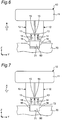
- the fitting determination unit 111 determines that the pressing surface 16 of the force-receiving portion 14 contacts with the opening edge 72 of the object to be assembled 70, as shown in Fig. 5 , when the force in the Z direction detected by each tactile sensor unit 13 is a specified value (for example, 2N) or more.
- the specified value is determined in advance according to a dimensional configuration of each finger 12, or a shape, size, material, and the like of the object being grasped 60.
- the fitting determination unit 111 determines that the fitting of the object being grasped 60 into the fitting recess 71 is completed, as shown in Fig. 7 , when the force in the Z direction detected by each tactile sensor unit 13 is a specified value (for example, 5N) or more.
- the fitting control unit 110 stops the palm 11 from moving close to the fitting recess 71 of the object to be assembled 70.
- a fitting process for fitting the object being grasped 60 into the fitting recess 71 of the object to be assembled 70 will be described.
- the fitting process described below is performed by the control device 100 executing a predetermined program.
- the fitting control unit 110 makes the palm 11 move close to the fitting recess 71 of the object to be assembled 70 with the object being grasped 60 grasped by each finger 12 (step S1).
- the fitting determination unit 111 determines whether the force in the Z direction detected by each tactile sensor unit 13 is the first specified value (for example, 2N) or more (step S2). When it is determined that the force in the Z direction detected by each tactile sensor unit 13 is less than the first specified value, the step S2 is repeated until the force in the Z direction detected by each tactile sensor unit 13 is the first specified value or more.
- the first specified value for example, 2N
- step S2 is repeated until the force in the Z direction detected by each tactile sensor unit 13 is the first specified value or more.
- the fitting determination unit 111 determines that the pressing surface 16 of the force-receiving portion 14 contacts with the opening edge 72 of the object to be assembled 70.
- the fitting control unit 110 stops the palm 11 from moving close to the fitting recess 71 of the object to be assembled 70, releases the grasp of the object being grasped 60 by each finger 12, and moves the palm 11 in the direction B away from the fitting recess 71 of the object to be assembled 70 (step S3).
- the fitting control unit 110 stops the palm 11 from moving in the direction B away from the fitting recess 71 of the object to be assembled 70, and makes the palm 11 approach the fitting recess 71 of the object to be assembled 70, again, with each finger 12 approached to each other and closed (step S4).
- the fitting determination unit 111 determines whether the force in the Z direction detected by each tactile sensor unit 13 is a second specified value (for example, 5N) or more (step S5). When the force detected by each tactile sensor unit 13 is less than the second specified value, the step S5 is repeated until a predetermined force is detected by each tactile sensor unit 13.
- a second specified value for example, 5N
- step S5 is repeated until a predetermined force is detected by each tactile sensor unit 13.
- the fitting determination unit 111 determines that the fitting of the object being grasped 60 into the fitting recess 71 is completed. As a result, the fitting control unit 110 stops the palm 11 from moving close to the fitting recess 71 of the object to be assembled 70 again (step S6), and the fitting process of the object being grasped 60 into the fitting recess 71 is completed.
- the fitting recess 71 of the object to be assembled 70 may include, for example, a through hole penetrating in the Z direction.
- the end effector 10 of the first embodiment includes the force-receiving portion 14 that is connected to the second end portion 122 of each finger 12 via the tactile sensor unit 13 and that receives a force from the object being grasped 60 when the object being grasped 60 is grasped by the plurality of fingers 12.
- the force-receiving portion 14 includes the grasping surface 15 and the pressing surface 16.
- the grasping surface 15 is placed facing the object being grasped 60 in a direction intersecting the extending direction of each finger 12 to be able to grasp the object being grasped 60.
- the pressing surface 16 is placed further away from the palm 11 than the second end portion 122 of each finger 12 in the extending direction of each finger 12 and extends in a direction intersecting the grasping surface 15.
- the force-receiving portion 14 covers the tactile sensor unit 13 in the extending direction of each finger 12 and in a direction intersecting the extending direction of each finger 12. With such a configuration, it is possible to more reliably press the object being grasped 60 against the object to be assembled 70 with the pressing surface 16 of the force-receiving portion 14.
- the end effector device 1 of the first embodiment it is possible to realize the end effector device 1 capable of fitting the object being grasped 60 into the fitting recess 71 of the object to be assembled 70 with a simple configuration by the end effector 10.
- the control unit 100 includes the fitting control unit 110.
- the fitting control unit 110 fits the object being grasped 60 into the fitting recess 71 by making the palm 11 approach the object being grasped 60 and pressing the object being grasped 60 against the object to be assembled 70 with the pressing surface 16 in a state where each finger 12 approaches each other in the direction intersecting the extending direction of each finger 12 and is closed after releasing the grasp of the object being grasped 60 by each finger 12 and moving the palm 11 in the direction B away from the object being grasped 60. It is possible to realize the end effector device 1 capable of fitting the object being grasped 60 into the fitting recess
- the fitting control unit 110 further includes the fitting determination unit 111 that determines whether the fitting of the object being grasped 60 into the fitting recess 71 is completed based on the detection result detected by each tactile sensor unit 13 when pressing the object being grasped 60 against the object to be assembled 70 with the pressing surface 16 and fitting the object being grasped 60 into the fitting recess 71.
- the fitting determination unit 111 makes it possible reliably to fit the object being grasped 60 into the fitting recess 71 of the object to be assembled 70.
- the end effector 10 includes a palm 11, a plurality of fingers 12 capable of grasping operation of grasping the object being grasped 60, a tactile sensor unit 13 capable of detecting an external force from the object being grasped 60, and a force-receiving portion 14 having a grasping surface 15 and a pressing surface 16.
- the end effector 10 is not limited to the configuration of the first embodiment.
- the tactile sensor unit 13 is provided at the second end portion 122 of each finger 12 and configured to be able to detect an external force from the object being grasped 60.
- the configuration and type of the end effector 10 may be set according to the dimensional configuration of each finger 12 or the shape, size, material, and the like of the object being grasped 60.
- the force-receiving portion 14 is not limited to the case where it is configured by the first plate member 141 and the second plate member 142.
- the force-receiving portion 14 may be configured of only the first plate member 141.
- a tip surface of the first plate member 141 farther from the palm 11 in the Z direction constitutes the pressing surface 16.
- the force-receiving portion 14 may be configured to include a connecting portion 17 provided on either the first plate member 141 or the second plate member 142, for example, as shown in Fig. 9 .
- the connecting portion 17 may be configured of, for example, an elastic member such as metal or rubber.
- the first plate member 141 is connected to the finger 12 via the tactile sensor unit 13
- the second plate member 142 is connected to the finger 12 via the connecting portion 17. With such a configuration, the durability of the force-receiving portion 14 can be improved.
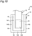
- the force-receiving portion 14 may be configured to include, for example, as shown in Fig. 10 , a first pressing surface 16 and a second pressing surface 18 extending in a direction intersecting the grasping surface 15 and the first pressing surface 16.
- the end effector 10 of Fig. 10 includes the first plate member 141 having the grasping surface 15, the second plate member 142 having the first pressing surface 16, and a third plate member 143 having the second pressing surface 18.
- the third plate member 143 intersects (for example, orthogonal to) the first plate member 141 and the second plate member 142.
- An elastic member such as metal or rubber may be attached to surfaces constituting the grasping surface 15 and the pressing surface 16 of the first plate member 141 and the second plate member 142.
- physical characteristics such as a friction coefficient of the grasping surface 15 and the pressing surface 16 can be changed as needed.
- a maintainability of the force-receiving portion 14 can be improved.
- the force-receiving portion 14 includes a grasping surface 15 and a pressing surface 16.
- the grasping surface 15 is placed facing the object being grasped 60 in a direction intersecting the extending direction of each finger 12 (for example, the Y direction) to be able to grasp the object being grasped 60 and receives a force in a direction intersecting the extending direction of each finger 12.
- the pressing surface 16 is placed further away from the palm 11 than the second end portion 122 of each finger 12 in the extending direction (for example, Z direction) of each finger 12 and extends in a direction intersecting the grasping surface 15 to receive a force in the extending direction of each finger 12.
- the grasping surface 15, the pressing surface 16 and each member constituting the force-receiving portion 14 may have shapes and sizes that is appropriately set according to the dimensional configuration of each finger 12, the shape, size and material of the object being grasped 60, or the like.
- the end effector device 1 of the second embodiment of the present disclosure differs from the first embodiment, as shown in Fig. 12 , in that the control device 100 includes a position shift direction determination unit 120 and a position shift correction unit 130 in addition to the fitting control unit 110.
- the same parts as those in the first embodiment are designated by the same reference numbers, the description thereof will not be repeated, and the points different from those in the first embodiment will be described.
- Each of the position shift direction determination unit 120 and the position shift correction unit 130 is a function realized by the CPU executing a predetermined program.
- the position shift direction determination unit 120 determines in which direction the object being grasped 60 is position-shifted with respect to the fitting recess 71 based on the detection result detected by each of the tactile sensor units 13 in a case where at least one of the external forces in at least three axial directions detected by each tactile sensor unit 13 is a specified value or more when the palm 11 approaches the fitting recess 71 of the object to be assembled 70 in a state where the object being grasped 60 is grasped by each finger 12 and fitting the object being grasped 60 into the fitting recess 71 (for example, in a case where the force in the Z direction detected by each tactile sensor unit 13 is 2N or more, and it is determined by the fitting determination unit 111 that the object being grasped 60 and the opening edge 72 of the fitting recess 71 are in contact with each other) .
- Fig. 13 shows a coordinate system of the tactile sensor unit 13 of the first finger 1201, a coordinate system of the tactile sensor unit 13 of the second finger 1202, and a coordinate system of the object being grasped 60.
- the position shift direction determination unit 120 determines in which of the three axial directions the position shift of the object being grasped 60 with respect to the fitting recess 71 occurs based on a sum or difference of the forces in the X, Y, and Z directions detected by each tactile sensor unit 13 when it is determined that the object being grasped 60 contacts with the opening edge 72 of the fitting recess 71.
- a position shift of the object being grasped 60 with respect to the fitting recess 71 in the Y direction is determined by a difference in force in the Y direction (that is, FY1 - FY2) or a difference in force in the Z direction (that is, FZ1 - FZ2).
- FY1 - FY2 or FZ1 - FZ2 is a positive value, it is determined that the object being grasped 60 is position-shifted in a positive direction of Y with respect to the fitting recess 71.
- the position shift of the object being grasped 60 with respect to the fitting recess 71 in the Y direction is determined by the difference in force in the Z direction (that is, FZ1 - FZ2) before it is determined that the object being grasped 60 contacts with the opening edge 72 (that is, the inclined surface 721) of the object to be assembled 70 and is determined by the difference in force in the Y direction (that is, FY1 - FY2) after it is determined that the object being grasped 60 contacts with the opening edge 72 of the object to be assembled 70.
- a position shift of the object being grasped 60 with respect to the fitting recess 71 in the X direction is determined by a difference in force in the X direction (that is, FX1 - FX2).
- FX1 - FX2 is a negative value, it is determined that the object being grasped 60 is shifted in a positive direction of X with respect to the fitting recess 71.
- a position shift of the object being grasped 60 with respect to the fitting recess 71 around the Z direction is determined by a sum of forces in the X direction (that is, FX1 + FX2).
- FX1 + FX2 is a positive value, it is determined that the object being grasped 60 is shifted around a rotation direction shown by ⁇ Z in Fig. 13 (that is, counterclockwise when viewed in a direction from the positive position on the Z axis toward the origin).
- the position shift direction determination unit 120 determines whether to complete the correction of position shift of the object being grasped 60 with respect to the fitting recess 71 based on whether one or more of or all of a sum and differences of the external forces in the same axial direction among the external forces in the three axial directions detected by each tactile sensor unit 13 (for example, FX1-FX2, FY1-FY2, FZ1-FZ2, FX1 + FX2) are a specified value (for example, 0.1N) or less. This specified value is determined in advance according to the dimensional configuration of each finger 12 or the shape, size, material, and the like of the object being grasped 60.
- the position shift direction determination unit 120 may determine whether the object being grasped 60 contacts the opening edge 72 of the fitting recess 71 at one point based on the difference in force in the X direction (that is, FX1 - FX2) and the difference in force in the Z direction (that is, FZ1 - FZ2).
- the object being grasped 60 contacts the opening edge 72 at one point, the object being grasped 60 is position-shifted with respect to the fitting recess 71 around the X direction (that is, around a ⁇ X direction in Fig. 13 ) and/or around the Y direction (that is, around a ⁇ Y direction in Fig. 13 ).
- the position shift correction unit 130 controls the drive device 30 to move the object being grasped 60 in a direction opposite to a position shift direction (in other words, in a direction having the same axis as and the different direction from the position shift direction) of the object being grasped 60 with respect to the fitting recess 71 determined by the position shift direction determination unit 120, thereby correcting the position shift of the object being grasped 60 with respect to the fitting recess 71.
- the position shift direction determination unit 120 determines that the object being grasped 60 is shifted in the positive direction of X with respect to the fitting recess 71.
- the position shift correction unit 130 controls the drive device 30 to drive at least one of the palm 11 and each finger 12 so that the object being grasped 60 moves in a negative direction of X by a specified amount (for example, 0.05 mm).
- the position shift correction unit 130 When correcting the position shift of the object being grasped 60 with respect to the fitting recess 71, in a case where the sum of forces in the Z direction (that is, FZ1 + FZ2) detected by each tactile sensor unit 13 exceeds a specified value (for example, 2N), and it is determined by the position shift direction determination unit 120 that the object being grasped 60 contacts with the opening edge 72 of the fitting recess 71, the position shift correction unit 130 temporarily suspends the position shift correction, and moves the object being grasped 60 in the Z direction as well as a direction away from the fitting recess 71 of the object to be assembled 70, until the sum of forces in the Z direction (that is, FZ1 + FZ2) detected by each tactile sensor unit 13 is the specified value (for example, 2N) or less.
- a specified value for example, 2N
- the position shift direction determination unit 120 determines that the contact of the object being grasped 60 with respect to the opening edge 72 of the fitting recess 71 cannot be maintained.
- the position shift correction unit 130 When it is determined that the contact of the object being grasped 60 with respect to the opening edge 72 of the fitting recess 71 cannot be maintained, the position shift correction unit 130 temporarily suspends the position shift correction, and moves the object being grasped 60 in the Z direction as well as a direction approaching the fitting recess 71 of the object to be assembled 70, until the sum of forces in the Z direction detected by each tactile sensor unit 13 is the specified value or more (that is, FZ1 + FZ2 ⁇ 1N).
- the fitting determination unit 111 determines whether the object being grasped 60 contacts with the opening edge 72 of the fitting recess 71 on the basis of whether the sum of forces in the Z direction (that is, FZ1 + FZ2) detected by each tactile sensor unit 13 exceeds a specified value (for example, 2N) when the object being grasped 60 approaches the fitting recess 71 of the object to be assembled 70 from the Z direction.
- the specified value is determined in advance according to the dimensional configuration of each finger 12, or the shape, size, material, and the like of the object being grasped 60.
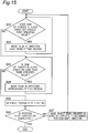
- a position shift correction process of the object being grasped 60 with respect to the object to be assembled 70 during the fitting process of fitting the object being grasped 60 into the fitting recess 71 of the object to be assembled 70 will be described.
- the fitting process described below is performed by the control device 100 executing a predetermined program.
- step S2 when it is determined in step S2 that the force in the Z direction detected by each tactile sensor unit 13 is the first specified value or more, the fitting control unit 110 stops the palm 11 from moving close to the fitting recess 71 of the object to be assembled 70 (step S11), and the position shift direction determination unit 120 determines whether the object being grasped 60 is position-shifted with respect to the fitting recess 71 (step S12).
- the position shift correction unit 130 determines whether the sum of forces in the Z direction (that is, FZ1 + FZ2) detected by each tactile sensor unit 13 exceeds the first specified value (for example, 2N) (step S21). When it is determined that the sum of forces in the Z direction detected by each tactile sensor unit 13 exceeds the first specified value, the position shift correction unit 130 does not perform the position shift correction, and moves the object being grasped 60 in the Z direction as well as a direction away from the fitting recess 71 of the object to be assembled 70, until the sum of forces in the Z direction detected by each tactile sensor unit 130 is the first specified value or less (step S22).
- the position shift direction determination unit 120 determines whether the sum of forces in the Z direction detected by each tactile sensor unit 13 is less than a third specified value (for example, 1N) (step S23). When it is determined that the sum of forces in the Z direction detected by each tactile sensor unit 13 is less than the third specified value (for example, 1N), the position shift correction unit 130 does not perform the position shift correction, and moves the object being grasped 60 in the Z direction as well as a direction approaching the fitting recess 71 of the object to be assembled 70, until the sum of forces in the Z direction detected by each tactile sensor unit 13 is the third specified value or more (step S24).
- a third specified value for example, 1N
- the position shift direction determination unit 120 determines a position shift direction of the object being grasped 60 with respect to the fitting recess 71 (step S25), and determines whether to complete the position shift correction of the object being grasped 60 with respect to the fitting recess 71 (step S26).
- step S3 the fitting control unit 110 releases the grasp of the object being grasped 60 by each finger 12, and moves the palm 11 in the direction B away from the fitting recess 71 of the object to be assembled 70.
- step S26 the position shift correction unit 130 moves the object being grasped 60 in a direction opposite to the position shift direction of the object being grasped 60 with respect to the fitting recess 71 determined by the position shift direction determination unit 120 to correct the position shift of the object being grasped 60 with respect to the fitting recess 71 (step S26). Then, returning to step S21, the position shift correction unit 130 determines whether the sum of forces in the Z direction detected by each tactile sensor unit 13 exceeds the first specified value.
- the end effector device 1 of the second embodiment in a case where the object being grasped 60 and the opening edge 72 of the fitting recess 71 contacts with each other when the palm 11 approaches the fitting recess 71 of the object to be assembled 70 and fitting the object being grasped 60 into the fitting recess 71 of the object to be assembled 70 in a state where the object being grasped 60 is grasped by each finger 12, it is determined whether the object being grasped 60 is position-shifted with respect to the fitting recess 71 based on the detection result detected by each tactile sensor unit 13, and the palm 11 moves in the direction opposite to a direction of the determined position shift of the object being grasped 60 with respect to the fitting recess 71 to correct the position shift of the object being grasped 60 with respect to the fitting recess 71.
- an end effector device 1 capable of correcting the position shift of the object being grasped 60 with respect to the fitting recess 71 of the object to be assembled 70.
- the position shift direction determination unit 120 determines the position shift direction of the object being grasped 60 with respect to the fitting recess 71 based on one or more of or all of the sum and differences of the external forces in the same axial direction among the external forces in the at least three axial directions detected by each tactile sensor unit 13. As a result, the position shift direction of the object being grasped 60 with respect to the fitting recess 71 can be determined with a simple configuration.
- the position shift correction unit 130 completes the correction of the position shift of the object being grasped 60 with respect to the fitting recess 71 when one or more of or all of the sum and differences of the external forces in the same axial direction among the external forces in the at least three axial directions detected by each tactile sensor unit 13 are the specified value or less. As a result, it is possible to determine whether the correction of the position shift of the object being grasped 60 with respect to the fitting recess 71 is completed with a simple configuration.
- the end effector 10 includes a plate-shaped first finger 1201 and a plate-shaped second finger 1202 as a plurality of fingers 12, and a force-receiving portion 14.
- the plate-shaped first finger 1201 and the plate-shaped second finger 1202 are arranged so that the plate surfaces face each other.
- the force-receiving portion 14 is connected to the second end portion 122 of each finger 1201, 1202 via the tactile sensor unit 13 and receives a force from the object being grasped 60 when the first finger 1201 and the second finger 1202 grasp the object being grasped 60.
- the force-receiving portion 14 has a grasping surface 15 and a pressing surface 16.
- the grasping surface 15 is placed facing the object being grasped 60 in the direction intersecting the extending direction of each finger 1201, 1202 to be able to grasp the object being grasped 60 and receives the force in the direction intersecting the extending direction of each finger 1201, 1202.
- the pressing surface 16 is placed further away from the palm 11 than the second end portion 122 of each finger 1201, 1202 in the extending direction of each finger 1201, 1202 and extends in a direction intersecting the grasping surface 15 to receive a force in the extending direction of each finger 1201, 1202.
- an end effector device 1 capable of fitting the object being grasped 60 into the fitting recess 71 of the object to be assembled 70 with a simple configuration and correcting the position shift of the object being grasped 60 with respect to the fitting recess 71 of the object to be assembled 70.
- the tactile sensor unit 13 can detect an external force in at least three axial directions.
- a configuration and type of the tactile sensor unit 13 can be set according to a dimensional configuration of each finger 12 or a shape, size, material, and the like of the object being grasped 60.
- the tactile sensor unit 13 may be configured to be able to detect only external forces in the three axial directions orthogonal to one another, or may be configured to be able to detect moments in each axial direction in addition to the external forces in the three axial directions orthogonal to one another.
- the tactile sensor unit 13 is configured to be able to detect moments in each axial direction in addition to the external forces in the three axial directions orthogonal to one another, for example, the position shift of the object being grasped 60 with respect to the fitting recess 71 in the Y direction can be determined by a difference in moments in the X-axis direction.
- the difference in moments in the X-axis direction is a negative value
- the position shift of the object being grasped 60 with respect to the fitting recess 71 in the X direction can be determined by the difference in moments in the Y-axis direction.
- the difference in moments in the Y-axis direction is a positive value, it is determined that the object being grasped 60 is shifted in the positive direction of X with respect to the fitting recess 71.
- the position shift of the object being grasped 60 with respect to the fitting recess 71 around the Z direction can be determined by a sum of moments in the Z-axis direction.
- the sum of moments in the Z-axis direction is a positive value, it is determined that the object being grasped 60 is shifted around the rotation direction shown by ⁇ Z in Fig. 13 .
- the end effector 10 includes a palm 11, a plurality of fingers 12 capable of grasping operation of grasping the object being grasped 60, and a tactile sensor unit 13 capable of detecting an external force from the object being grasped 60.
- the end effector 10 is not limited to the configuration of the second embodiment.
- the position shift direction determination unit 120 is not limited to the second embodiment.
- the position shift direction determination unit 120 may have any configuration that can determine whether the object being grasped 60 is position-shifted with respect to the fitting recess 71 in at least one of the three axial directions based on the detection result detected by the tactile sensor unit 13.
- the position shift correction unit 130 is not limited to the second embodiment.
- the position shift correction unit 130 may have any configuration that can correct the position shift of the object being grasped 60 with respect to the fitting recess 71 by moving the palm 11 in a direction opposite to the position shift direction of the object being grasped 60 with respect to the fitting recess 71 determined by the position shift direction determination unit 120.
- An end effector 10 of a first aspect of the present disclosure includes:
- the end effector 10 of the first aspect for example, after grasping it by the grasping surface 15 of the force-receiving portion 14 and moving the object being grasped 60 to the fitting recess 71 of the object to be assembled 70, it is possible to press the object being grasped 60 against the object to be assembled 70 with the pressing surface 16 of the force-receiving portion 14 to fit the object being grasped 60 into the fitting recess 71. That is, it is possible to realize an end effector 10 including a tactile sensor unit 13 capable of fitting the object being grasped 60 into the fitting recess 71 of the object to be assembled 70 with a simple configuration.
- the force receiving portion 14 covers the tactile sensor unit 13 in the extending direction and in a direction intersecting the extending direction.
- the end effector 10 of the second aspect it is possible to more reliably press the object being grasped 60 against the object to be assembled 70 with the pressing surface 16 of the force-receiving portion 14.
- the force receiving portion 14 includes a first pressing surface 16 that is the pressing surface, and a second pressing surface 18 that extends in a direction intersecting the grasping surface 15 and the first pressing surface 16.
- the object being grasped 60 can be fitted into the fitting recess 71 of the object to be assembled 70 in various aspects.
- the force receiving portion 14 includes a first plate member 141 including the grasping surface, a second plate member 142 including the pressing surface, and a connecting portion 17 provided on either the first plate member 141 or the second plate member 142, one of the first plate member 141 and the second plate member 142 is connected to the second end portion 122 of each of the plurality of fingers 12 via the tactile sensor unit 13, and the other of the first plate member 141 and the second plate member 142 is connected to the second end portion 122 of each of the plurality of fingers 12 via the connecting portion 17.
- the durability of the force-receiving portion 14 can be improved.
- an end effector 10 according to any one of the above aspects; a drive device 30 that drives the palm 11 and each of the plurality of fingers 12; and a control device 100 that controls the drive device 30 based on a detection result detected by the tactile sensor unit 13.
- the end effector device 1 of the fifth aspect it is possible to realize the end effector device 1 capable of fitting the object being grasped 60 into the fitting recess 71 of the object to be assembled 70 with a simple configuration by the end effector 10.
- the control device 100 includes a fitting control unit 110 that releases the grasp of the object being grasped 60 by each of the plurality of fingers 12 and moves the palm 11 in a direction away from a fitting recess 71 of an object to be assembled 70 in a case where the tactile sensor unit 13 detects that the pressing surface 16 of the force receiving portion 14 contacts with an opening edge 72 of the fitting recess 71 when the palm 11 approaches the fitting recess 71 in a state where the object being grasped 60 is grasped by each of the plurality of fingers 12 to fit the object being grasped 60 into the fitting recess 71.
- the end effector device 1 of the sixth aspect it is possible to realize the end effector device 1 capable of fitting the object being grasped 60 into the fitting recess 71 of the object to be assembled 70 with a simple control process by the fitting control unit 110.
- the fitting control unit 110 moves the palm 11 closer to the fitting recess 71 of the object to be assembled 70 again in a state where each of the plurality of fingers 12 approaches each other and is closed in a direction intersecting the extending direction after moving the palm 11 in a direction away from the fitting recess 71, so that the object being grasped 60 is pressed against the object to be assembled 70 with the pressing surface 16 to fit the object being grasped 60 into the fitting recess 71.
- the end effector device 1 of the seventh aspect it is possible to realize the end effector device 1 capable of fitting the object being grasped 60 into the fitting recess 71 of the object to be assembled 70 with a simple control process by the fitting control unit 110.
- the drive device 30 includes an encoder that detects rotation of a motor that drives the palm 11, and the fitting control unit 110 further includes a fitting determination unit 111 that determines whether the fitting of the object being grasped 60 into the fitting recess 71 is completed based on the detection result or based on both the detection result and information output from the encoder when pressing the object being grasped 60 against the object to be assembled 70 with the pressing surface 16 to fit the object being grasped 60 into the fitting recess 71, and the fitting control unit 110 stops the palm 11 from moving closer to the object being grasped 60 when it is determined that the fitting of the object being grasped 60 into the fitting recess 71 is completed.
- the end effector device 1 of the eighth aspect it is possible more reliably to fit the object being grasped 60 into the fitting recess 71 of the object to be assembled 70 by the fitting determination unit 111.
- the end effector of the present disclosure can be applied to, for example, an end effector device of an industrial robot.
- the end effector device of the present disclosure can be applied to, for example, an industrial robot.
Landscapes
- Engineering & Computer Science (AREA)
- Robotics (AREA)
- Mechanical Engineering (AREA)
- Human Computer Interaction (AREA)
- Manipulator (AREA)
Abstract
Description
- The present disclosure relates to an end effector including a tactile sensor unit, and to an end effector device including the end effector.
-
Patent Literature 1 discloses a robot control device including a force sense measuring device that acquires information on force sense acting on an object being grasped by a robot hand. This force sense measuring device is composed of a force sensor, and is provided at a portion of the robot hand that contacts with an object being grasped. - PTL 1:
JP 2017-087325 A - When it is attempted to fit an object being grasped into a recess of an object to be assembled while grasping the object being grasped by the robot hand using the robot control device, the robot hand may contacts with the edge of the opening of the recess in the middle of fitting the object being grasped into the recess. In this case, in order to fit the object being grasped into the recess, it is necessary to rotate the robot hand by about 90 degrees and press the object being grasped with a portion where the force sense measuring device is provided. Thus, the structure and control of the robot hand may be complicated.
- The present disclosure provides an end effector including a tactile sensor unit capable of fitting an object being grasped into a fitting recess of an object to be assembled with a simple configuration, and an end effector device including the end effector.
- An end effector of an example of the present disclosure includes:
- a palm;
- a plurality of fingers capable of grasping operation in which each of the plurality of fingers moves in a direction intersecting an extending direction thereof as well as approaching each other and grasps an object being grasped, a first end portion of each of the plurality of fingers in the extending direction being connected to the palm;
- a tactile sensor unit capable of detecting an external force from the object being grasped, the tactile sensor being provided at a second end portion of each of the plurality of fingers in the extending direction; and
- a force receiving portion that receives a force from the object being grasped when the object being grasped is grasped by the plurality of fingers, the force receiving portion being connected to the second end portion of each of the plurality of fingers via the tactile sensor unit, wherein
- the force receiving portion includes
- a grasping surface that receives a force in the direction intersecting the extending direction, the grasping surface being placed facing the object being grasped in a direction intersecting the extending direction to be able to grasp the object being grasped, and
- a pressing surface that receive a force in the extending direction, the pressing surface being placed further away from the palm than the second end portion of each of the plurality of fingers in the extending direction and extending in a direction intersecting the grasping surface.
- An end effector device of an example of the present disclosure includes:
- the end effector;
- a drive device that drives the palm and each of the plurality of fingers; and
- a control device that controls the drive device based on a detection result detected by the tactile sensor unit.
- The end effector includes a force receiving portion that is connected to the second end portion of each finger via the tactile sensor unit. The force receiving portion receives a force from the object being grasped when the object being grasped is grasped by the plurality of fingers. The force receiving portion includes a grasping surface and a pressing surface. The grasping surface is placed facing the object being grasped in a direction intersecting the extending direction to be able to grasp the object being grasped. The pressing surface is placed further away from the palm than the second end portion of each of the plurality of fingers and that extends in a direction intersecting the grasping surface. With such a configuration, for example, the object being grasped is grasped by the grasping surface of the force receiving portion and moved to the fitting recess of the object to be assembled and, then, the object being grasped is pressed against the object to be assembled with the pressing surface of the force receiving portion, so that the object being grasped is fitted into the fitting recess. That is, it is possible to realize an end effector including a tactile sensor unit capable of fitting the object being grasped into the fitting recess of the object to be assembled with a simple configuration.
- According to the end effector device, it is possible to realize an end effector device capable of fitting an object being grasped into a fitting recess of an object to be assembled with a simple configuration by the end effector.
-
-
Fig. 1 is a block diagram showing an end effector device according to a first embodiment of the present disclosure. -
Fig. 2 is a front view showing an end effector of the end effector device ofFig. 1 . -
Fig. 3 is an enlarged front view showing a finger of the end effector ofFig. 2 . -
Fig. 4 is a first diagram for explaining a fitting process of the end effector device ofFig. 1 . -
Fig. 5 is a second diagram for explaining the fitting process of the end effector device ofFig. 1 . -
Fig. 6 is a third diagram for explaining the fitting process of the end effector device ofFig. 1 . -
Fig. 7 is a fourth diagram for explaining the fitting process of the end effector device ofFig. 1 . -
Fig. 8 is an enlarged front view of a finger showing a first modification of the end effector ofFig. 2 . -
Fig. 9 is an enlarged front view of a finger showing a second modification of the end effector ofFig. 2 . -
Fig. 10 is an enlarged front view of a finger showing a third modification of the end effector ofFig. 2 . -
Fig. 11 is a flowchart for explaining the fitting process of the end effector device ofFig. 1 . -
Fig. 12 is a block diagram showing an end effector device according to a second embodiment of the present disclosure. -
Fig. 13 is a front view for explaining a coordinate system of the end effector device ofFig. 12 . -
Fig. 14 is a first flowchart for explaining a position shift correction process of the end effector device ofFig. 12 . -
Fig. 15 is a second flowchart for explaining the position shift correction process of the end effector device ofFig. 12 . - Hereinafter, an example of the present disclosure will be described with reference to the accompanying drawings. Note that, in the following description, although terms indicating a specific direction or position (for example, terms including "up", "down", "right", "left") will be used as necessary, they are used for facilitating understanding of the present disclosure with reference to the drawings, and the technical scope of the present disclosure is not limited by the meaning of those terms. It should be noted that the following description is merely exemplary in nature and is not intended to limit the present disclosure, its application, or its use. Furthermore, the drawings are schematic, and the ratios of the dimensions do not always match actual ones.
- An
end effector 10 of the first embodiment of the present disclosure constitutes a part of anend effector device 1 such as a manipulator, for example, as shown inFig. 1 . As an example, theend effector device 1 includes anend effector 10, anarm 20 connected to theend effector 10, adrive device 30 that drives theend effector 10 and thearm 20, acontrol device 100 that controls thedrive device 30, anoperation unit 40 connected to thecontrol device 100, and apower source 50 that supplies power to thedrive device 30 and thecontrol device 100. Thecontrol device 100 controls drive of theend effector 10 and thearm 20 by outputting a command to thedrive device 30 based on operation received by theoperation unit 40. Thearm 20 is connected to apalm 11 described later of theend effector 10, and can move so as to be able to arbitrarily change a position and posture of theend effector 10 by thedrive device 30. Thedrive device 30 has a motor (not shown) that drives thepalm 11 and eachfinger 12, and an encoder (not shown) that detects the rotation of the motor, and is configured to output information detected by the encoder to thecontrol device 100. - As shown in
Fig. 2 , theend effector 10 includes thepalm 11, a plurality of fingers 12 (twofingers 12 in the first embodiment) connected to thepalm 11, and atactile sensor unit 13 and a force-receivingportion 14 provided at eachfinger 12. - Each
finger 12 has afirst end portion 121 provided with one end of eachfinger 12 in an extending direction of thefinger 12. Thefirst end portion 121 is connected to thepalm 11. Eachfinger 12 is configured capable of grasping operation in which eachfinger 12 moves in a direction intersecting the extending direction thereof as well as approaching each other and grasps an object being grasped 60. - Specifically, as an example, each
finger 12 has a substantially rectangular plate shape having substantially the same length in the extending direction thereof. Eachfinger 12 is placed side by side and substantially in parallel with anotherfinger 12 so that their plate surfaces face each other. Eachfinger 12 is configured to be movable in a direction orthogonal to the plate surface by thedrive device 30. The motor that drives eachfinger 12 may be configured by, for example, a linear motor. -
Tactile sensor unit 13, for example, is configured of a capacitance type or resistance type planar tactile sensor.Tactile sensor unit 13 is provided at asecond end portion 122, which is a tip portion provided with the other end of eachfinger 12 in the extending direction thereof, in a state capable of detecting an external force from the object being grasped 60. - Specifically, each
tactile sensor unit 13 is configured to be able to detect an external force in at least three axial directions by detecting a minute displacement/deformation as an electrical change, the minute displacement/deformation being caused by force that each force-receivingportion 14 receives from the object being grasped 60. In this embodiment, as shown inFig. 2 ,tactile sensor unit 13 is configured to be able to detect at least a force in a Z direction along the extending direction of eachfinger 12, a force in a Y direction orthogonal to the Z direction and directed from onefinger 12 to theother finger 12, and a force in a X direction (that is, the paper penetration direction inFig. 2 ) orthogonal to the Z direction and the Y direction. - Each force-receiving
portion 14 is configured of metal, as an example. Each force-receivingportion 14 is connected to thesecond end portion 122 of each of the plurality offingers 12 via thetactile sensor unit 13. Each force-receivingportion 14 is configured to receive a force from the object being grasped 60 when the object being grasped 60 is grasped by the plurality offingers 12. - Specifically, each force-receiving
portion 14 includes afirst plate member 141 extending in the extending direction of eachfinger 12 and asecond plate member 142 extending in a direction intersecting (for example, orthogonal to) thefirst plate member 141 as well as being away from each other. - The
first plate member 141 has a graspingsurface 15. The graspingsurface 15 is placed facing the object being grasped 60 in a direction intersecting the extending direction of eachfinger 12 to be able to grasp the object being grasped 60. The graspingsurface 15 receives a force in the direction intersecting the extending direction of eachfinger 12. Further, thesecond plate member 142 has apressing surface 16. Thepressing surface 16 is placed further away from thepalm 11 than thesecond end portion 122 of eachfinger 12 in the extending direction of eachfinger 12. Thepressing surface 16 extends in the direction intersecting (for example, orthogonal to) the graspingsurface 15. Thepressing surface 16 receives a force in the extending direction of eachfinger 12. That is, the force-receivingportion 14 covers thetactile sensor unit 13 in the extending direction of eachfinger 12 and in the direction intersecting the extending direction of eachfinger 12. - Next, the
control device 100 of theend effector device 1 will be described. - The
control device 100 includes a CPU that performs calculation, a storage medium such as a ROM and a RAM that store program, data, or the like necessary for control of theend effector 10, and an interface unit that performs input/output of signals with an outside of theend effector device 1. Thecontrol device 100 includes afitting control unit 110 as shown inFig. 1 . Thefitting control unit 110 is a function realized by the CPU executing a predetermined program. - The
fitting control unit 110 presses the object being grasped 60 against the object to be assembled 70 with thepressing surface 16 so that the object being grasped 60 is fitted into thefitting recess 71 when thetactile sensor unit 13 detects that thepressing surface 16 of the force-receivingportion 14 contacts with an openingedge 72 of thefitting recess 71 in a case where thepalm 11 approaches afitting recess 71 of an object to be assembled 70 (seeFig. 4 ) from the Z direction (that is, thepalm 11 moves in an arrow A direction inFig. 4 ) and the object being grasped 60 is fitted into thefitting recess 71 in a state where the object being grasped 60 is grasped by eachfinger 12. - Specifically, as shown in
Fig. 5 , when thetactile sensor unit 13 detects that thepressing surface 16 of the force-receivingportion 14 contacts with the openingedge 72 of thefitting recess 71, as shown inFig. 6 , thefitting control unit 110 releases grasp of the object being grasped 60 by eachfinger 12, and moves thepalm 11 in a direction B away from thefitting recess 71 of the object to be assembled 70 in the Z direction. Then, as shown inFig. 7 , thefitting control unit 110 makes thepalm 11 approach thefitting recess 71 of the object to be assembled 70 from the Z direction, again, in a state in which eachfinger 12 approaches each other and closed in the Y direction (that is, the direction intersecting the extending direction of each finger 12), to press the object being grasped 60 against the object to be assembled 70 with thepressing surface 16, thereby fitting the object being grasped 60 into thefitting recess 71. - A movement of the
palm 11 in the direction B away from thefitting recess 71 of the object to be assembled 70 in the Z direction is performed until thepalm 11 reaches a position at which thesecond end portion 122 of eachfinger 12 is further away from thefitting recess 71 of the object to be assembled 70 than the object being grasped 60 in the Z direction. Thefitting control unit 110 calculates an amount of movement of thepalm 11 based on information output from an encoder that detects a rotation of the motor of thedrive device 30 that drives thepalm 11, for example. - The
fitting control unit 110 further includes afitting determination unit 111 that determines whether the fitting of the object being grasped 60 into thefitting recess 71 is completed based on the detection result detected by eachtactile sensor unit 13 when pressing the object being grasped 60 against the object to be assembled 70 with thepressing surface 16 to fit the object being grasped 60 into thefitting recess 71. - For example, when the
palm 11 approaches thefitting recess 71 of the object to be assembled 70 from the Z direction in a state where the object being grasped 60 is grasped by eachfinger 12, thefitting determination unit 111 determines that thepressing surface 16 of the force-receivingportion 14 contacts with the openingedge 72 of the object to be assembled 70, as shown inFig. 5 , when the force in the Z direction detected by eachtactile sensor unit 13 is a specified value (for example, 2N) or more. The specified value is determined in advance according to a dimensional configuration of eachfinger 12, or a shape, size, material, and the like of the object being grasped 60. - With each
finger 12 closed, when thepalm 11 approaches thefitting recess 71 of the object to be assembled 70 from the Z direction and pressing the object being grasped 60 against the object to be assembled 70 with thepressing surface 16, thefitting determination unit 111 determines that the fitting of the object being grasped 60 into thefitting recess 71 is completed, as shown inFig. 7 , when the force in the Z direction detected by eachtactile sensor unit 13 is a specified value (for example, 5N) or more. When it is determined that the fitting of the object being grasped 60 into thefitting recess 71 is completed, thefitting control unit 110 stops thepalm 11 from moving close to thefitting recess 71 of the object to be assembled 70. - It may be configured that whether the fitting of the object being grasped 60 into the
fitting recess 71 is completed is determined based on both the detection result detected by eachtactile sensor unit 13 and the information output from the encoder. - Subsequently, with reference to
Fig. 11 , a fitting process for fitting the object being grasped 60 into thefitting recess 71 of the object to be assembled 70 will be described. The fitting process described below is performed by thecontrol device 100 executing a predetermined program. - As shown in
Fig. 11 , when the fitting process is started, thefitting control unit 110 makes thepalm 11 move close to thefitting recess 71 of the object to be assembled 70 with the object being grasped 60 grasped by each finger 12 (step S1). - At this time, the
fitting determination unit 111 determines whether the force in the Z direction detected by eachtactile sensor unit 13 is the first specified value (for example, 2N) or more (step S2). When it is determined that the force in the Z direction detected by eachtactile sensor unit 13 is less than the first specified value, the step S2 is repeated until the force in the Z direction detected by eachtactile sensor unit 13 is the first specified value or more. - When it is determined that the force in the Z direction detected by each
tactile sensor unit 13 is the first specified value or more, thefitting determination unit 111 determines that thepressing surface 16 of the force-receivingportion 14 contacts with the openingedge 72 of the object to be assembled 70. As a result, thefitting control unit 110 stops thepalm 11 from moving close to thefitting recess 71 of the object to be assembled 70, releases the grasp of the object being grasped 60 by eachfinger 12, and moves thepalm 11 in the direction B away from thefitting recess 71 of the object to be assembled 70 (step S3). - When the
palm 11 moves in the direction B away from thefitting recess 71 of the object to be assembled 70, and thesecond end portion 122 of eachfinger 12 reaches a position at which thesecond end portion 122 further away from thefitting recess 71 of the object to be assembled 70 than the object being grasped 60, thefitting control unit 110 stops thepalm 11 from moving in the direction B away from thefitting recess 71 of the object to be assembled 70, and makes thepalm 11 approach thefitting recess 71 of the object to be assembled 70, again, with eachfinger 12 approached to each other and closed (step S4). - At this time, the
fitting determination unit 111 determines whether the force in the Z direction detected by eachtactile sensor unit 13 is a second specified value (for example, 5N) or more (step S5). When the force detected by eachtactile sensor unit 13 is less than the second specified value, the step S5 is repeated until a predetermined force is detected by eachtactile sensor unit 13. - When it is determined that the force in the Z direction detected by each
tactile sensor unit 13 is the specification or more, thefitting determination unit 111 determines that the fitting of the object being grasped 60 into thefitting recess 71 is completed. As a result, thefitting control unit 110 stops thepalm 11 from moving close to thefitting recess 71 of the object to be assembled 70 again (step S6), and the fitting process of the object being grasped 60 into thefitting recess 71 is completed. - The
fitting recess 71 of the object to be assembled 70 may include, for example, a through hole penetrating in the Z direction. - The
end effector 10 of the first embodiment includes the force-receivingportion 14 that is connected to thesecond end portion 122 of eachfinger 12 via thetactile sensor unit 13 and that receives a force from the object being grasped 60 when the object being grasped 60 is grasped by the plurality offingers 12. The force-receivingportion 14 includes the graspingsurface 15 and thepressing surface 16. The graspingsurface 15 is placed facing the object being grasped 60 in a direction intersecting the extending direction of eachfinger 12 to be able to grasp the object being grasped 60. Thepressing surface 16 is placed further away from thepalm 11 than thesecond end portion 122 of eachfinger 12 in the extending direction of eachfinger 12 and extends in a direction intersecting the graspingsurface 15. With such a configuration, for example, after grasping it by the graspingsurface 15 of the force-receivingportion 14 and moving the object being grasped 60 to thefitting recess 71 of the object to be assembled 70, it is possible to press the object being grasped 60 against the object to be assembled 70 with thepressing surface 16 of the force-receivingportion 14 to fit the object being grasped 60 into thefitting recess 71. That is, it is possible to realize anend effector 10 including atactile sensor unit 13 capable of fitting the object being grasped 60 into thefitting recess 71 of the object to be assembled 70 with a simple configuration. - The force-receiving
portion 14 covers thetactile sensor unit 13 in the extending direction of eachfinger 12 and in a direction intersecting the extending direction of eachfinger 12. With such a configuration, it is possible to more reliably press the object being grasped 60 against the object to be assembled 70 with thepressing surface 16 of the force-receivingportion 14. - According to the
end effector device 1 of the first embodiment, it is possible to realize theend effector device 1 capable of fitting the object being grasped 60 into thefitting recess 71 of the object to be assembled 70 with a simple configuration by theend effector 10. - The
control unit 100 includes thefitting control unit 110. In a case where thetactile sensor unit 13 detects that thepressing surface 16 of the force-receivingportion 14 contacts with the openingedge 72 of thefitting recess 71 when thepalm 11 approaches thefitting recess 71 of the object to be assembled 70 in a state where the object being grasped 60 is grasped by eachfinger 12 to fit the object being grasped 60 into thefitting recess 71, thefitting control unit 110 fits the object being grasped 60 into thefitting recess 71 by making thepalm 11 approach the object being grasped 60 and pressing the object being grasped 60 against the object to be assembled 70 with thepressing surface 16 in a state where eachfinger 12 approaches each other in the direction intersecting the extending direction of eachfinger 12 and is closed after releasing the grasp of the object being grasped 60 by eachfinger 12 and moving thepalm 11 in the direction B away from the object being grasped 60. It is possible to realize theend effector device 1 capable of fitting the object being grasped 60 into thefitting recess 71 of the object to be assembled 70 with a simple control process by thefitting control unit 110. - Since the object being grasped 60 is pressed against the object to be assembled 70 in a state where each
finger 12 approaches each other in the direction intersecting the extending direction of eachfinger 12 and closed, as compared with the case where the object being grasped 60 is fitted into thefitting recess 71 with the object being grasped 60 grasped by eachfinger 12, or as compared with the case where the object being grasped 60 is pressed using any of thefingers 12 against the object to be assembled 70 with eachfinger 12 open to each other, the load applied to eachfinger 12 is reduced. As a result, a highly durableend effector device 1 can be realized. - The
fitting control unit 110 further includes thefitting determination unit 111 that determines whether the fitting of the object being grasped 60 into thefitting recess 71 is completed based on the detection result detected by eachtactile sensor unit 13 when pressing the object being grasped 60 against the object to be assembled 70 with thepressing surface 16 and fitting the object being grasped 60 into thefitting recess 71. Thefitting determination unit 111 makes it possible reliably to fit the object being grasped 60 into thefitting recess 71 of the object to be assembled 70. - It is sufficient that the
end effector 10 includes apalm 11, a plurality offingers 12 capable of grasping operation of grasping the object being grasped 60, atactile sensor unit 13 capable of detecting an external force from the object being grasped 60, and a force-receivingportion 14 having a graspingsurface 15 and apressing surface 16. Theend effector 10 is not limited to the configuration of the first embodiment. - In the
end effector 10 of the first embodiment, it is sufficient that thetactile sensor unit 13 is provided at thesecond end portion 122 of eachfinger 12 and configured to be able to detect an external force from the object being grasped 60. The configuration and type of theend effector 10 may be set according to the dimensional configuration of eachfinger 12 or the shape, size, material, and the like of the object being grasped 60. - The force-receiving
portion 14 is not limited to the case where it is configured by thefirst plate member 141 and thesecond plate member 142. For example, as shown inFig. 8 , the force-receivingportion 14 may be configured of only thefirst plate member 141. In this case, a tip surface of thefirst plate member 141 farther from thepalm 11 in the Z direction constitutes thepressing surface 16. - The force-receiving
portion 14 may be configured to include a connectingportion 17 provided on either thefirst plate member 141 or thesecond plate member 142, for example, as shown inFig. 9 . The connectingportion 17 may be configured of, for example, an elastic member such as metal or rubber. In theend effector 10 ofFig. 9 , as an example, thefirst plate member 141 is connected to thefinger 12 via thetactile sensor unit 13, and thesecond plate member 142 is connected to thefinger 12 via the connectingportion 17. With such a configuration, the durability of the force-receivingportion 14 can be improved. - The force-receiving
portion 14 may be configured to include, for example, as shown inFig. 10 , a firstpressing surface 16 and a secondpressing surface 18 extending in a direction intersecting the graspingsurface 15 and the first pressingsurface 16. Theend effector 10 ofFig. 10 includes thefirst plate member 141 having the graspingsurface 15, thesecond plate member 142 having the first pressingsurface 16, and athird plate member 143 having the secondpressing surface 18. Thethird plate member 143 intersects (for example, orthogonal to) thefirst plate member 141 and thesecond plate member 142. With such a configuration, the object being grasped 60 can be fitted into thefitting recess 71 of the object to be assembled 70 in various aspects. - An elastic member such as metal or rubber may be attached to surfaces constituting the grasping
surface 15 and thepressing surface 16 of thefirst plate member 141 and thesecond plate member 142. With such a configuration, physical characteristics such as a friction coefficient of the graspingsurface 15 and thepressing surface 16 can be changed as needed. In addition, a maintainability of the force-receivingportion 14 can be improved. - In this way, it is sufficient that the force-receiving
portion 14 includes a graspingsurface 15 and apressing surface 16. The graspingsurface 15 is placed facing the object being grasped 60 in a direction intersecting the extending direction of each finger 12 (for example, the Y direction) to be able to grasp the object being grasped 60 and receives a force in a direction intersecting the extending direction of eachfinger 12. Thepressing surface 16 is placed further away from thepalm 11 than thesecond end portion 122 of eachfinger 12 in the extending direction (for example, Z direction) of eachfinger 12 and extends in a direction intersecting the graspingsurface 15 to receive a force in the extending direction of eachfinger 12. The graspingsurface 15, thepressing surface 16 and each member constituting the force-receivingportion 14 may have shapes and sizes that is appropriately set according to the dimensional configuration of eachfinger 12, the shape, size and material of the object being grasped 60, or the like. - The
end effector device 1 of the second embodiment of the present disclosure differs from the first embodiment, as shown inFig. 12 , in that thecontrol device 100 includes a position shiftdirection determination unit 120 and a position shift correction unit 130 in addition to thefitting control unit 110. In the second embodiment, the same parts as those in the first embodiment are designated by the same reference numbers, the description thereof will not be repeated, and the points different from those in the first embodiment will be described. - Each of the position shift
direction determination unit 120 and the position shift correction unit 130 is a function realized by the CPU executing a predetermined program. - The position shift
direction determination unit 120 determines in which direction the object being grasped 60 is position-shifted with respect to thefitting recess 71 based on the detection result detected by each of thetactile sensor units 13 in a case where at least one of the external forces in at least three axial directions detected by eachtactile sensor unit 13 is a specified value or more when thepalm 11 approaches thefitting recess 71 of the object to be assembled 70 in a state where the object being grasped 60 is grasped by eachfinger 12 and fitting the object being grasped 60 into the fitting recess 71 (for example, in a case where the force in the Z direction detected by eachtactile sensor unit 13 is 2N or more, and it is determined by thefitting determination unit 111 that the object being grasped 60 and the openingedge 72 of thefitting recess 71 are in contact with each other) . - For example, forces in the X, Y, and Z directions detected by each
tactile sensor unit 13 placed on theright finger 12 inFig. 2 (hereinafter referred to as a first finger 1201) of the twofingers 12 are FX1, FY1, and FZ1, respectively. Forces in the X, Y, and Z directions detected by eachtactile sensor unit 13 placed on theleft finger 12 inFig. 2 (hereinafter referred to as a second finger 1202) of the twofingers 12 are FX2, FY2, and FZ2, respectively.Fig. 13 shows a coordinate system of thetactile sensor unit 13 of thefirst finger 1201, a coordinate system of thetactile sensor unit 13 of thesecond finger 1202, and a coordinate system of the object being grasped 60. - In this case, the position shift
direction determination unit 120 determines in which of the three axial directions the position shift of the object being grasped 60 with respect to thefitting recess 71 occurs based on a sum or difference of the forces in the X, Y, and Z directions detected by eachtactile sensor unit 13 when it is determined that the object being grasped 60 contacts with the openingedge 72 of thefitting recess 71. - For example, a position shift of the object being grasped 60 with respect to the
fitting recess 71 in the Y direction is determined by a difference in force in the Y direction (that is, FY1 - FY2) or a difference in force in the Z direction (that is, FZ1 - FZ2). When FY1 - FY2 or FZ1 - FZ2 is a positive value, it is determined that the object being grasped 60 is position-shifted in a positive direction of Y with respect to thefitting recess 71. - When an
inclined surface 721 is formed on the openingedge 72 of thefitting recess 71, the position shift of the object being grasped 60 with respect to thefitting recess 71 in the Y direction is determined by the difference in force in the Z direction (that is, FZ1 - FZ2) before it is determined that the object being grasped 60 contacts with the opening edge 72 (that is, the inclined surface 721) of the object to be assembled 70 and is determined by the difference in force in the Y direction (that is, FY1 - FY2) after it is determined that the object being grasped 60 contacts with the openingedge 72 of the object to be assembled 70. - A position shift of the object being grasped 60 with respect to the
fitting recess 71 in the X direction is determined by a difference in force in the X direction (that is, FX1 - FX2). When FX1 - FX2 is a negative value, it is determined that the object being grasped 60 is shifted in a positive direction of X with respect to thefitting recess 71. - A position shift of the object being grasped 60 with respect to the
fitting recess 71 around the Z direction is determined by a sum of forces in the X direction (that is, FX1 + FX2). When FX1 + FX2 is a positive value, it is determined that the object being grasped 60 is shifted around a rotation direction shown by θZ inFig. 13 (that is, counterclockwise when viewed in a direction from the positive position on the Z axis toward the origin). - The position shift
direction determination unit 120 determines whether to complete the correction of position shift of the object being grasped 60 with respect to thefitting recess 71 based on whether one or more of or all of a sum and differences of the external forces in the same axial direction among the external forces in the three axial directions detected by each tactile sensor unit 13 (for example, FX1-FX2, FY1-FY2, FZ1-FZ2, FX1 + FX2) are a specified value (for example, 0.1N) or less. This specified value is determined in advance according to the dimensional configuration of eachfinger 12 or the shape, size, material, and the like of the object being grasped 60. - The position shift
direction determination unit 120 may determine whether the object being grasped 60 contacts the openingedge 72 of thefitting recess 71 at one point based on the difference in force in the X direction (that is, FX1 - FX2) and the difference in force in the Z direction (that is, FZ1 - FZ2). When the object being grasped 60 contacts the openingedge 72 at one point, the object being grasped 60 is position-shifted with respect to thefitting recess 71 around the X direction (that is, around a θX direction inFig. 13 ) and/or around the Y direction (that is, around a θY direction inFig. 13 ). - The position shift correction unit 130 controls the
drive device 30 to move the object being grasped 60 in a direction opposite to a position shift direction (in other words, in a direction having the same axis as and the different direction from the position shift direction) of the object being grasped 60 with respect to thefitting recess 71 determined by the position shiftdirection determination unit 120, thereby correcting the position shift of the object being grasped 60 with respect to thefitting recess 71. - For example, it is assumed that the position shift
direction determination unit 120 determines that the object being grasped 60 is shifted in the positive direction of X with respect to thefitting recess 71. In this case, the position shift correction unit 130 controls thedrive device 30 to drive at least one of thepalm 11 and eachfinger 12 so that the object being grasped 60 moves in a negative direction of X by a specified amount (for example, 0.05 mm). - When correcting the position shift of the object being grasped 60 with respect to the
fitting recess 71, in a case where the sum of forces in the Z direction (that is, FZ1 + FZ2) detected by eachtactile sensor unit 13 exceeds a specified value (for example, 2N), and it is determined by the position shiftdirection determination unit 120 that the object being grasped 60 contacts with the openingedge 72 of thefitting recess 71, the position shift correction unit 130 temporarily suspends the position shift correction, and moves the object being grasped 60 in the Z direction as well as a direction away from thefitting recess 71 of the object to be assembled 70, until the sum of forces in the Z direction (that is, FZ1 + FZ2) detected by eachtactile sensor unit 13 is the specified value (for example, 2N) or less. - When correcting the position shift of the object being grasped 60 with respect to the
fitting recess 71, in a case where the sum of forces in the Z direction detected by eachtactile sensor unit 13 is less than a specified value (for example, 1N) (that is, FZ1 + FZ2 < 1N), the position shiftdirection determination unit 120 determines that the contact of the object being grasped 60 with respect to the openingedge 72 of thefitting recess 71 cannot be maintained. When it is determined that the contact of the object being grasped 60 with respect to the openingedge 72 of thefitting recess 71 cannot be maintained, the position shift correction unit 130 temporarily suspends the position shift correction, and moves the object being grasped 60 in the Z direction as well as a direction approaching thefitting recess 71 of the object to be assembled 70, until the sum of forces in the Z direction detected by eachtactile sensor unit 13 is the specified value or more (that is, FZ1 + FZ2 □ 1N). - In the second embodiment, the
fitting determination unit 111 determines whether the object being grasped 60 contacts with the openingedge 72 of thefitting recess 71 on the basis of whether the sum of forces in the Z direction (that is, FZ1 + FZ2) detected by eachtactile sensor unit 13 exceeds a specified value (for example, 2N) when the object being grasped 60 approaches thefitting recess 71 of the object to be assembled 70 from the Z direction. The specified value is determined in advance according to the dimensional configuration of eachfinger 12, or the shape, size, material, and the like of the object being grasped 60. - Subsequently, with reference to
Figs. 14 and15 , a position shift correction process of the object being grasped 60 with respect to the object to be assembled 70 during the fitting process of fitting the object being grasped 60 into thefitting recess 71 of the object to be assembled 70 will be described. The fitting process described below is performed by thecontrol device 100 executing a predetermined program. - As shown in
Fig. 14 , when it is determined in step S2 that the force in the Z direction detected by eachtactile sensor unit 13 is the first specified value or more, thefitting control unit 110 stops thepalm 11 from moving close to thefitting recess 71 of the object to be assembled 70 (step S11), and the position shiftdirection determination unit 120 determines whether the object being grasped 60 is position-shifted with respect to the fitting recess 71 (step S12). - In this position shift correction, as shown in
Fig. 15 , the position shift correction unit 130 determines whether the sum of forces in the Z direction (that is, FZ1 + FZ2) detected by eachtactile sensor unit 13 exceeds the first specified value (for example, 2N) (step S21). When it is determined that the sum of forces in the Z direction detected by eachtactile sensor unit 13 exceeds the first specified value, the position shift correction unit 130 does not perform the position shift correction, and moves the object being grasped 60 in the Z direction as well as a direction away from thefitting recess 71 of the object to be assembled 70, until the sum of forces in the Z direction detected by each tactile sensor unit 130 is the first specified value or less (step S22). - When it is determined that the sum of forces in the Z direction detected by each
tactile sensor unit 13 does not exceed the first specified value, the position shiftdirection determination unit 120 determines whether the sum of forces in the Z direction detected by eachtactile sensor unit 13 is less than a third specified value (for example, 1N) (step S23). When it is determined that the sum of forces in the Z direction detected by eachtactile sensor unit 13 is less than the third specified value (for example, 1N), the position shift correction unit 130 does not perform the position shift correction, and moves the object being grasped 60 in the Z direction as well as a direction approaching thefitting recess 71 of the object to be assembled 70, until the sum of forces in the Z direction detected by eachtactile sensor unit 13 is the third specified value or more (step S24). - When it is determined that the sum of forces in the Z direction detected by each
tactile sensor unit 13 is not less than the third specified value (for example, 1N), the position shiftdirection determination unit 120 determines a position shift direction of the object being grasped 60 with respect to the fitting recess 71 (step S25), and determines whether to complete the position shift correction of the object being grasped 60 with respect to the fitting recess 71 (step S26). - When it is determined to complete the position shift correction, the process proceeds to step S3, where the
fitting control unit 110 releases the grasp of the object being grasped 60 by eachfinger 12, and moves thepalm 11 in the direction B away from thefitting recess 71 of the object to be assembled 70. When it is determined not to complete the position shift correction, the position shift correction unit 130 moves the object being grasped 60 in a direction opposite to the position shift direction of the object being grasped 60 with respect to thefitting recess 71 determined by the position shiftdirection determination unit 120 to correct the position shift of the object being grasped 60 with respect to the fitting recess 71 (step S26). Then, returning to step S21, the position shift correction unit 130 determines whether the sum of forces in the Z direction detected by eachtactile sensor unit 13 exceeds the first specified value. - In the
end effector device 1 of the second embodiment, in a case where the object being grasped 60 and the openingedge 72 of thefitting recess 71 contacts with each other when thepalm 11 approaches thefitting recess 71 of the object to be assembled 70 and fitting the object being grasped 60 into thefitting recess 71 of the object to be assembled 70 in a state where the object being grasped 60 is grasped by eachfinger 12, it is determined whether the object being grasped 60 is position-shifted with respect to thefitting recess 71 based on the detection result detected by eachtactile sensor unit 13, and thepalm 11 moves in the direction opposite to a direction of the determined position shift of the object being grasped 60 with respect to thefitting recess 71 to correct the position shift of the object being grasped 60 with respect to thefitting recess 71. With such a configuration, it is possible to realize anend effector device 1 capable of correcting the position shift of the object being grasped 60 with respect to thefitting recess 71 of the object to be assembled 70. - The position shift
direction determination unit 120 determines the position shift direction of the object being grasped 60 with respect to thefitting recess 71 based on one or more of or all of the sum and differences of the external forces in the same axial direction among the external forces in the at least three axial directions detected by eachtactile sensor unit 13. As a result, the position shift direction of the object being grasped 60 with respect to thefitting recess 71 can be determined with a simple configuration. - The position shift correction unit 130 completes the correction of the position shift of the object being grasped 60 with respect to the
fitting recess 71 when one or more of or all of the sum and differences of the external forces in the same axial direction among the external forces in the at least three axial directions detected by eachtactile sensor unit 13 are the specified value or less. As a result, it is possible to determine whether the correction of the position shift of the object being grasped 60 with respect to thefitting recess 71 is completed with a simple configuration. - The
end effector 10 includes a plate-shapedfirst finger 1201 and a plate-shapedsecond finger 1202 as a plurality offingers 12, and a force-receivingportion 14. The plate-shapedfirst finger 1201 and the plate-shapedsecond finger 1202 are arranged so that the plate surfaces face each other. The force-receivingportion 14 is connected to thesecond end portion 122 of eachfinger tactile sensor unit 13 and receives a force from the object being grasped 60 when thefirst finger 1201 and thesecond finger 1202 grasp the object being grasped 60. The force-receivingportion 14 has a graspingsurface 15 and apressing surface 16. The graspingsurface 15 is placed facing the object being grasped 60 in the direction intersecting the extending direction of eachfinger finger pressing surface 16 is placed further away from thepalm 11 than thesecond end portion 122 of eachfinger finger surface 15 to receive a force in the extending direction of eachfinger end effector device 1 capable of fitting the object being grasped 60 into thefitting recess 71 of the object to be assembled 70 with a simple configuration and correcting the position shift of the object being grasped 60 with respect to thefitting recess 71 of the object to be assembled 70. - In the
end effector device 1 of the second embodiment, it is sufficient that thetactile sensor unit 13 can detect an external force in at least three axial directions. A configuration and type of thetactile sensor unit 13 can be set according to a dimensional configuration of eachfinger 12 or a shape, size, material, and the like of the object being grasped 60. For example, thetactile sensor unit 13 may be configured to be able to detect only external forces in the three axial directions orthogonal to one another, or may be configured to be able to detect moments in each axial direction in addition to the external forces in the three axial directions orthogonal to one another. - When the
tactile sensor unit 13 is configured to be able to detect moments in each axial direction in addition to the external forces in the three axial directions orthogonal to one another, for example, the position shift of the object being grasped 60 with respect to thefitting recess 71 in the Y direction can be determined by a difference in moments in the X-axis direction. - When the difference in moments in the X-axis direction is a negative value, it is determined that the object being grasped 60 is shifted in the positive direction of Y with respect to the
fitting recess 71. The position shift of the object being grasped 60 with respect to thefitting recess 71 in the X direction can be determined by the difference in moments in the Y-axis direction. When the difference in moments in the Y-axis direction is a positive value, it is determined that the object being grasped 60 is shifted in the positive direction of X with respect to thefitting recess 71. - The position shift of the object being grasped 60 with respect to the
fitting recess 71 around the Z direction can be determined by a sum of moments in the Z-axis direction. When the sum of moments in the Z-axis direction is a positive value, it is determined that the object being grasped 60 is shifted around the rotation direction shown by θZ inFig. 13 . - It is sufficient that the
end effector 10 includes apalm 11, a plurality offingers 12 capable of grasping operation of grasping the object being grasped 60, and atactile sensor unit 13 capable of detecting an external force from the object being grasped 60. Theend effector 10 is not limited to the configuration of the second embodiment. - The position shift
direction determination unit 120 is not limited to the second embodiment. The position shiftdirection determination unit 120 may have any configuration that can determine whether the object being grasped 60 is position-shifted with respect to thefitting recess 71 in at least one of the three axial directions based on the detection result detected by thetactile sensor unit 13. - The position shift correction unit 130 is not limited to the second embodiment. The position shift correction unit 130 may have any configuration that can correct the position shift of the object being grasped 60 with respect to the
fitting recess 71 by moving thepalm 11 in a direction opposite to the position shift direction of the object being grasped 60 with respect to thefitting recess 71 determined by the position shiftdirection determination unit 120. - As described above, various embodiments of the present disclosure have been described in detail with reference to the drawings, and finally, various aspects of the present disclosure will be described. It is to be noted that in the following description, description will be provided with reference numerals attached thereto as an example.
- An
end effector 10 of a first aspect of the present disclosure includes: - a
palm 11; - a plurality of
fingers 12 capable of grasping operation in which each of the plurality offingers 12 moves in a direction intersecting an extending direction thereof as well as approaching each other and grasps an object being grasped 60, afirst end portion 121 of each of the plurality offingers 12 in the extending direction being connected to thepalm 11; - a
tactile sensor unit 13 capable of detecting an external force from the object being grasped 60, thetactile sensor 13 being provided at asecond end portion 121 of each of the plurality offingers 12 in the extending direction; and - a
force receiving portion 14 that receives a force from the object being grasped 60 when the object being grasped 60 is grasped by the plurality offingers 12, theforce receiving portion 14 being connected to thesecond end portion 122 of each of the plurality offingers 12 via thetactile sensor unit 13, wherein - the
force receiving portion 14 includes- a grasping
surface 15 that receives a force in the direction intersecting the extending direction, the graspingsurface 15 being placed facing the object being grasped 60 in a direction intersecting the extending direction to be able to grasp the object being grasped 60, and - a
pressing surface 16 that receive a force in the extending direction, thepressing surface 16 being placed further away from thepalm 11 than thesecond end portion 122 of each of the plurality offingers 12 in the extending direction and extending in a direction intersecting the graspingsurface 15.
- a grasping
- According to the
end effector 10 of the first aspect, for example, after grasping it by the graspingsurface 15 of the force-receivingportion 14 and moving the object being grasped 60 to thefitting recess 71 of the object to be assembled 70, it is possible to press the object being grasped 60 against the object to be assembled 70 with thepressing surface 16 of the force-receivingportion 14 to fit the object being grasped 60 into thefitting recess 71. That is, it is possible to realize anend effector 10 including atactile sensor unit 13 capable of fitting the object being grasped 60 into thefitting recess 71 of the object to be assembled 70 with a simple configuration. - In an
end effector 10 of a second aspect of the present disclosure,
theforce receiving portion 14 covers thetactile sensor unit 13 in the extending direction and in a direction intersecting the extending direction. - According to the
end effector 10 of the second aspect, it is possible to more reliably press the object being grasped 60 against the object to be assembled 70 with thepressing surface 16 of the force-receivingportion 14. - In an
end effector 10 of a third aspect of the present disclosure,
theforce receiving portion 14 includes
a firstpressing surface 16 that is the pressing surface, and
a secondpressing surface 18 that extends in a direction intersecting the graspingsurface 15 and the first pressingsurface 16. - According to the
end effector 10 of the third aspect, the object being grasped 60 can be fitted into thefitting recess 71 of the object to be assembled 70 in various aspects. - In an
end effector 10 of a fourth aspect of the present disclosure,
theforce receiving portion 14 includes
afirst plate member 141 including the grasping surface,
asecond plate member 142 including the pressing surface, and
a connectingportion 17 provided on either thefirst plate member 141 or thesecond plate member 142,
one of thefirst plate member 141 and thesecond plate member 142 is connected to thesecond end portion 122 of each of the plurality offingers 12 via thetactile sensor unit 13, and
the other of thefirst plate member 141 and thesecond plate member 142 is connected to thesecond end portion 122 of each of the plurality offingers 12 via the connectingportion 17. - According to the
end effector 10 of the fourth aspect, the durability of the force-receivingportion 14 can be improved. - In an
end effector device 1 according to a fifth aspect of the present disclosure,
anend effector 10 according to any one of the above aspects;
adrive device 30 that drives thepalm 11 and each of the plurality offingers 12; and
acontrol device 100 that controls thedrive device 30 based on a detection result detected by thetactile sensor unit 13. - According to the
end effector device 1 of the fifth aspect, it is possible to realize theend effector device 1 capable of fitting the object being grasped 60 into thefitting recess 71 of the object to be assembled 70 with a simple configuration by theend effector 10. - In an
end effector device 1 of a sixth aspect of the present disclosure,
thecontrol device 100 includes afitting control unit 110 that releases the grasp of the object being grasped 60 by each of the plurality offingers 12 and moves thepalm 11 in a direction away from afitting recess 71 of an object to be assembled 70 in a case where thetactile sensor unit 13 detects that thepressing surface 16 of theforce receiving portion 14 contacts with an openingedge 72 of thefitting recess 71 when thepalm 11 approaches thefitting recess 71 in a state where the object being grasped 60 is grasped by each of the plurality offingers 12 to fit the object being grasped 60 into thefitting recess 71. - According to the
end effector device 1 of the sixth aspect, it is possible to realize theend effector device 1 capable of fitting the object being grasped 60 into thefitting recess 71 of the object to be assembled 70 with a simple control process by thefitting control unit 110. - In an
end effector device 1 of a seventh aspect of the present disclosure,
thefitting control unit 110 moves thepalm 11 closer to thefitting recess 71 of the object to be assembled 70 again in a state where each of the plurality offingers 12 approaches each other and is closed in a direction intersecting the extending direction after moving thepalm 11 in a direction away from thefitting recess 71, so that the object being grasped 60 is pressed against the object to be assembled 70 with thepressing surface 16 to fit the object being grasped 60 into thefitting recess 71. - According to the
end effector device 1 of the seventh aspect, it is possible to realize theend effector device 1 capable of fitting the object being grasped 60 into thefitting recess 71 of the object to be assembled 70 with a simple control process by thefitting control unit 110. - In an
end effector device 1 of an eighth aspect of the present disclosure,
thedrive device 30 includes an encoder that detects rotation of a motor that drives thepalm 11, and
thefitting control unit 110 further includes afitting determination unit 111 that determines whether the fitting of the object being grasped 60 into thefitting recess 71 is completed based on the detection result or based on both the detection result and information output from the encoder when pressing the object being grasped 60 against the object to be assembled 70 with thepressing surface 16 to fit the object being grasped 60 into thefitting recess 71, and
thefitting control unit 110 stops thepalm 11 from moving closer to the object being grasped 60 when it is determined that the fitting of the object being grasped 60 into thefitting recess 71 is completed. - According to the
end effector device 1 of the eighth aspect, it is possible more reliably to fit the object being grasped 60 into thefitting recess 71 of the object to be assembled 70 by thefitting determination unit 111. - Note that, by appropriately combining any of the above-described various embodiments or modifications, it is possible to achieve the effects of the respective embodiments or modifications. In addition, a combination of the embodiments or a combination of the examples or a combination of the embodiment and the example is possible, and a combination of the features in the different embodiments or the examples is also possible.
- Although the present disclosure has been fully described in connection with preferred embodiments with reference to the accompanying drawings, various variations and modifications will be apparent to those skilled in the art. It is to be understood that such variations and modifications are included in the appended claims unless the variations and modifications depart from the scope of the present disclosure as set forth in the claims.
- The end effector of the present disclosure can be applied to, for example, an end effector device of an industrial robot.
- The end effector device of the present disclosure can be applied to, for example, an industrial robot.
-
- 1.
- end effector device
- 10.
- end effector
- 11.
- palm
- 12.
- finger
- 1201.
- first finger
- 1202.
- second finger
- 121.
- proximal end portion
- 122.
- tip portion
- 13.
- tactile sensor unit
- 14.
- force receiving portion
- 141.
- first plate member
- 142.
- second plate member
- 143.
- third plate member
- 15.
- grasping surface
- 16.
- pressing surface (first pressing surface)
- 17.
- connecting portion
- 18.
- second pressing surface
- 20.
- arm
- 30.
- drive device
- 40.
- operation unit
- 50.
- power source
- 60.
- object being grasped
- 70.
- object to be assembled
- 71.
- fitting recess
- 72.
- opening edge
- 100.
- control device
- 110.
- fitting control unit
- 111.
- fitting determination unit
- 120.
- position shift direction determination unit
- 130.
- position shift correction unit
Claims (8)
- An end effector comprising:a palm;a plurality of fingers capable of grasping operation in which each of the plurality of fingers moves in a direction intersecting an extending direction thereof as well as approaching each other and grasps an object being grasped, a first end portion of each of the plurality of fingers in the extending direction being connected to the palm;a tactile sensor unit capable of detecting an external force from the object being grasped, the tactile sensor being provided at a second end portion of each of the plurality of fingers in the extending direction; anda force receiving portion that receives a force from the object being grasped when the object being grasped is grasped by the plurality of fingers, the force receiving portion being connected to the second end portion of each of the plurality of fingers via the tactile sensor unit, whereinthe force receiving portion includesa grasping surface that receives a force in the direction intersecting the extending direction, the grasping surface being placed facing the object being grasped in a direction intersecting the extending direction to be able to grasp the object being grasped, anda pressing surface that receive a force in the extending direction, the pressing surface being placed further away from the palm than the second end portion of each of the plurality of fingers in the extending direction and extending in a direction intersecting the grasping surface.
- The end effector according to claim 1, wherein
the force receiving portion covers the tactile sensor unit in the extending direction and in a direction intersecting the extending direction. - The end effector according to claim 1 or 2, wherein
the force receiving portion includes
a first pressing surface that is the pressing surface, and
a second pressing surface that extends in a direction intersecting the grasping surface and the first pressing surface. - The end effector according to any one of claims 1 to 3, wherein
the force receiving portion includes
a first plate member including the grasping surface,
a second plate member including the pressing surface, and
a connecting portion provided on either the first plate member or the second plate member,
one of the first plate member and the second plate member is connected to the second end portion of each of the plurality of fingers via the tactile sensor unit, and
the other of the first plate member and the second plate member is connected to the second end portion of each of the plurality of fingers via the connecting portion. - An end effector device, comprising:an end effector according to any one of claims 1 to 4;a drive device that drives the palm and each of the plurality of fingers; anda control device that controls the drive device based on a detection result detected by the tactile sensor unit.
- The end effector device according to claim 5, wherein
the control device includes a fitting control unit that releases the grasp of the object being grasped by each of the plurality of fingers and moves the palm in a direction away from a fitting recess of an object to be assembled in a case where the tactile sensor unit detects that the pressing surface of the force receiving portion contacts with an opening edge of the fitting recess when the palm approaches the fitting recess in a state where the object being grasped is grasped by each of the plurality of fingers to fit the object being grasped into the fitting recess. - The end effector device according to claim 6, wherein
the fitting control unit moves the palm closer to the fitting recess of the object to be assembled again in a state where each of the plurality of fingers approaches each other and is closed in a direction intersecting the extending direction after moving the palm in a direction away from the fitting recess, so that the object being grasped is pressed against the object to be assembled with the pressing surface to fit the object being grasped into the fitting recess. - The end effector device according to claim 7, wherein
the drive device includes an encoder that detects rotation of a motor that drives the palm, and
the fitting control unit further includes a fitting determination unit that determines whether the fitting of the object being grasped into the fitting recess is completed based on the detection result or based on both the detection result and information output from the encoder when pressing the object being grasped against the object to be assembled with the pressing surface to fit the object being grasped into the fitting recess, and
the fitting control unit stops the palm from moving closer to the object being grasped when it is determined that the fitting of the object being grasped into the fitting recess is completed.
Applications Claiming Priority (2)
| Application Number | Priority Date | Filing Date | Title |
|---|---|---|---|
| JP2018180741A JP6988757B2 (en) | 2018-09-26 | 2018-09-26 | End effector and end effector device |
| PCT/JP2019/009562 WO2020066061A1 (en) | 2018-09-26 | 2019-03-11 | End effector and end effector device |
Publications (3)
| Publication Number | Publication Date |
|---|---|
| EP3831552A1 true EP3831552A1 (en) | 2021-06-09 |
| EP3831552A4 EP3831552A4 (en) | 2022-05-25 |
| EP3831552B1 EP3831552B1 (en) | 2026-03-04 |
Family
ID=69951213
Family Applications (1)
| Application Number | Title | Priority Date | Filing Date |
|---|---|---|---|
| EP19867875.7A Active EP3831552B1 (en) | 2018-09-26 | 2019-03-11 | End effector device |
Country Status (5)
| Country | Link |
|---|---|
| US (1) | US12017345B2 (en) |
| EP (1) | EP3831552B1 (en) |
| JP (1) | JP6988757B2 (en) |
| CN (1) | CN112638598B (en) |
| WO (1) | WO2020066061A1 (en) |
Families Citing this family (7)
| Publication number | Priority date | Publication date | Assignee | Title |
|---|---|---|---|---|
| US11389968B2 (en) * | 2019-10-02 | 2022-07-19 | Toyota Research Institute, Inc. | Systems and methods for determining pose of objects held by flexible end effectors |
| JP2021171840A (en) * | 2020-04-21 | 2021-11-01 | 株式会社デンソーウェーブ | Operation button assembly device |
| CN116723919A (en) | 2021-03-04 | 2023-09-08 | 索尼集团公司 | Robots, end effectors and robotic systems |
| TWI894450B (en) * | 2021-03-30 | 2025-08-21 | 日商發那科股份有限公司 | A control device that calculates the parameters for controlling the robot's position and posture |
| EP4419301A4 (en) * | 2021-10-19 | 2025-06-18 | Shanghai Flexiv Robotics Technology Co., Ltd. | GRIPPERS AND ROBOTS WITH IT |
| EP4442411A4 (en) * | 2021-11-29 | 2025-12-03 | Kyocera Corp | CONTROL DEVICE, ROBOT CONTROL SYSTEM AND ROBOT CONTROL METHOD |
| CN117245686A (en) * | 2022-06-16 | 2023-12-19 | 小仓离合器有限公司 | Manipulator |
Family Cites Families (15)
| Publication number | Priority date | Publication date | Assignee | Title |
|---|---|---|---|---|
| JPS57205092A (en) * | 1981-06-10 | 1982-12-16 | Nissan Motor | Finger having pressure sensing function |
| JPS60221287A (en) * | 1984-04-13 | 1985-11-05 | 三菱電機株式会社 | Force sensor for robot |
| US4715773A (en) * | 1985-06-04 | 1987-12-29 | Clemson University | Method and apparatus for repositioning a mislocated object with a robot hand |
| JPH08323678A (en) * | 1995-05-25 | 1996-12-10 | Sanyo Electric Co Ltd | Flexible object gripping device |
| JP3638162B2 (en) * | 1995-09-29 | 2005-04-13 | 沖電気工業株式会社 | Automatic insertion / removal robot for main wiring board connection pins |
| KR100511009B1 (en) * | 2002-11-21 | 2005-08-30 | 조창제 | Transfer device for gantry robot |
| JP4737456B2 (en) * | 2007-11-22 | 2011-08-03 | Smc株式会社 | Gripper mechanism |
| JP5345046B2 (en) * | 2009-11-30 | 2013-11-20 | 三菱電機株式会社 | Robot teaching device and robot control device |
| JP5993539B2 (en) * | 2011-01-06 | 2016-09-14 | セイコーエプソン株式会社 | Robot hand and robot |
| JP5776772B2 (en) * | 2011-06-28 | 2015-09-09 | 株式会社安川電機 | Robot hand and robot |
| JP2015112662A (en) * | 2013-12-10 | 2015-06-22 | Nok株式会社 | Coating material and coating structure of robot holding part |
| JP6400321B2 (en) * | 2014-03-31 | 2018-10-03 | 本田技研工業株式会社 | Work holding method |
| JP6518047B2 (en) | 2014-08-29 | 2019-05-22 | 川崎重工業株式会社 | End effector, industrial robot, and method of operating the same |
| JP6700726B2 (en) * | 2015-11-06 | 2020-05-27 | キヤノン株式会社 | Robot controller, robot control method, robot control system, and computer program |
| JP2017170586A (en) * | 2016-03-25 | 2017-09-28 | セイコーエプソン株式会社 | End effector, robot and robot control device |
-
2018
- 2018-09-26 JP JP2018180741A patent/JP6988757B2/en active Active
-
2019
- 2019-03-11 CN CN201980056663.6A patent/CN112638598B/en active Active
- 2019-03-11 US US17/273,505 patent/US12017345B2/en active Active
- 2019-03-11 WO PCT/JP2019/009562 patent/WO2020066061A1/en not_active Ceased
- 2019-03-11 EP EP19867875.7A patent/EP3831552B1/en active Active
Also Published As
| Publication number | Publication date |
|---|---|
| WO2020066061A1 (en) | 2020-04-02 |
| CN112638598B (en) | 2024-07-12 |
| JP2020049581A (en) | 2020-04-02 |
| CN112638598A (en) | 2021-04-09 |
| EP3831552B1 (en) | 2026-03-04 |
| US12017345B2 (en) | 2024-06-25 |
| EP3831552A4 (en) | 2022-05-25 |
| JP6988757B2 (en) | 2022-01-05 |
| US20210213627A1 (en) | 2021-07-15 |
Similar Documents
| Publication | Publication Date | Title |
|---|---|---|
| US12017345B2 (en) | End effector and end effector device | |
| US12427671B2 (en) | Systems and methods for providing contact detection in an articulated arm | |
| EP3831549A1 (en) | End effector device | |
| Gao et al. | Design and analysis of underactuated robotic gripper with adaptive fingers for objects grasping tasks | |
| EP3831551B1 (en) | End effector and end effector device | |
| JP2019202360A (en) | Robot control device, robot and robot system | |
| JP2014210330A (en) | Robot finger unit, robot hand, and robot | |
| JP2022113357A (en) | Tactile sensor device and robot hand device using the same |
Legal Events
| Date | Code | Title | Description |
|---|---|---|---|
| STAA | Information on the status of an ep patent application or granted ep patent |
Free format text: STATUS: THE INTERNATIONAL PUBLICATION HAS BEEN MADE |
|
| PUAI | Public reference made under article 153(3) epc to a published international application that has entered the european phase |
Free format text: ORIGINAL CODE: 0009012 |
|
| STAA | Information on the status of an ep patent application or granted ep patent |
Free format text: STATUS: REQUEST FOR EXAMINATION WAS MADE |
|
| 17P | Request for examination filed |
Effective date: 20210305 |
|
| AK | Designated contracting states |
Kind code of ref document: A1 Designated state(s): AL AT BE BG CH CY CZ DE DK EE ES FI FR GB GR HR HU IE IS IT LI LT LU LV MC MK MT NL NO PL PT RO RS SE SI SK SM TR |
|
| DAV | Request for validation of the european patent (deleted) | ||
| DAX | Request for extension of the european patent (deleted) | ||
| A4 | Supplementary search report drawn up and despatched |
Effective date: 20220426 |
|
| RIC1 | Information provided on ipc code assigned before grant |
Ipc: B25J 15/02 20060101ALI20220420BHEP Ipc: B25J 13/08 20060101ALI20220420BHEP Ipc: B25J 9/16 20060101ALI20220420BHEP Ipc: B25J 15/08 20060101AFI20220420BHEP |
|
| GRAP | Despatch of communication of intention to grant a patent |
Free format text: ORIGINAL CODE: EPIDOSNIGR1 |
|
| STAA | Information on the status of an ep patent application or granted ep patent |
Free format text: STATUS: GRANT OF PATENT IS INTENDED |
|
| INTG | Intention to grant announced |
Effective date: 20250528 |
|
| GRAJ | Information related to disapproval of communication of intention to grant by the applicant or resumption of examination proceedings by the epo deleted |
Free format text: ORIGINAL CODE: EPIDOSDIGR1 |
|
| STAA | Information on the status of an ep patent application or granted ep patent |
Free format text: STATUS: REQUEST FOR EXAMINATION WAS MADE |
|
| INTC | Intention to grant announced (deleted) | ||
| GRAP | Despatch of communication of intention to grant a patent |
Free format text: ORIGINAL CODE: EPIDOSNIGR1 |
|
| STAA | Information on the status of an ep patent application or granted ep patent |
Free format text: STATUS: GRANT OF PATENT IS INTENDED |
|
| INTG | Intention to grant announced |
Effective date: 20251007 |
|
| GRAS | Grant fee paid |
Free format text: ORIGINAL CODE: EPIDOSNIGR3 |
|
| GRAA | (expected) grant |
Free format text: ORIGINAL CODE: 0009210 |
|
| STAA | Information on the status of an ep patent application or granted ep patent |
Free format text: STATUS: THE PATENT HAS BEEN GRANTED |
|
| AK | Designated contracting states |
Kind code of ref document: B1 Designated state(s): AL AT BE BG CH CY CZ DE DK EE ES FI FR GB GR HR HU IE IS IT LI LT LU LV MC MK MT NL NO PL PT RO RS SE SI SK SM TR |
|
| REG | Reference to a national code |
Ref country code: CH Ref legal event code: F10 Free format text: ST27 STATUS EVENT CODE: U-0-0-F10-F00 (AS PROVIDED BY THE NATIONAL OFFICE) Effective date: 20260304 Ref country code: GB Ref legal event code: FG4D |
|
| REG | Reference to a national code |
Ref country code: DE Ref legal event code: R096 Ref document number: 602019082171 Country of ref document: DE |
|
| REG | Reference to a national code |
Ref country code: IE Ref legal event code: FG4D |
|
| PGFP | Annual fee paid to national office [announced via postgrant information from national office to epo] |
Ref country code: DE Payment date: 20260318 Year of fee payment: 8 |
|
| PG25 | Lapsed in a contracting state [announced via postgrant information from national office to epo] |
Ref country code: RS Free format text: LAPSE BECAUSE OF FAILURE TO SUBMIT A TRANSLATION OF THE DESCRIPTION OR TO PAY THE FEE WITHIN THE PRESCRIBED TIME-LIMIT Effective date: 20260604 |
|
| PG25 | Lapsed in a contracting state [announced via postgrant information from national office to epo] |
Ref country code: ES Free format text: LAPSE BECAUSE OF FAILURE TO SUBMIT A TRANSLATION OF THE DESCRIPTION OR TO PAY THE FEE WITHIN THE PRESCRIBED TIME-LIMIT Effective date: 20260304 |
|
| REG | Reference to a national code |
Ref country code: NL Ref legal event code: MP Effective date: 20260304 |
|
| PG25 | Lapsed in a contracting state [announced via postgrant information from national office to epo] |
Ref country code: PL Free format text: LAPSE BECAUSE OF FAILURE TO SUBMIT A TRANSLATION OF THE DESCRIPTION OR TO PAY THE FEE WITHIN THE PRESCRIBED TIME-LIMIT Effective date: 20260304 |
|
| PG25 | Lapsed in a contracting state [announced via postgrant information from national office to epo] |
Ref country code: GR Free format text: LAPSE BECAUSE OF FAILURE TO SUBMIT A TRANSLATION OF THE DESCRIPTION OR TO PAY THE FEE WITHIN THE PRESCRIBED TIME-LIMIT Effective date: 20260605 |
|
| REG | Reference to a national code |
Ref country code: LT Ref legal event code: MG9D |
|
| PG25 | Lapsed in a contracting state [announced via postgrant information from national office to epo] |
Ref country code: LT Free format text: LAPSE BECAUSE OF FAILURE TO SUBMIT A TRANSLATION OF THE DESCRIPTION OR TO PAY THE FEE WITHIN THE PRESCRIBED TIME-LIMIT Effective date: 20260304 |
|
| PG25 | Lapsed in a contracting state [announced via postgrant information from national office to epo] |
Ref country code: NO Free format text: LAPSE BECAUSE OF FAILURE TO SUBMIT A TRANSLATION OF THE DESCRIPTION OR TO PAY THE FEE WITHIN THE PRESCRIBED TIME-LIMIT Effective date: 20260604 |
|
| PG25 | Lapsed in a contracting state [announced via postgrant information from national office to epo] |
Ref country code: FI Free format text: LAPSE BECAUSE OF FAILURE TO SUBMIT A TRANSLATION OF THE DESCRIPTION OR TO PAY THE FEE WITHIN THE PRESCRIBED TIME-LIMIT Effective date: 20260304 Ref country code: SE Free format text: LAPSE BECAUSE OF FAILURE TO SUBMIT A TRANSLATION OF THE DESCRIPTION OR TO PAY THE FEE WITHIN THE PRESCRIBED TIME-LIMIT Effective date: 20260304 |
|
| PG25 | Lapsed in a contracting state [announced via postgrant information from national office to epo] |
Ref country code: HR Free format text: LAPSE BECAUSE OF FAILURE TO SUBMIT A TRANSLATION OF THE DESCRIPTION OR TO PAY THE FEE WITHIN THE PRESCRIBED TIME-LIMIT Effective date: 20260304 |
|
| PG25 | Lapsed in a contracting state [announced via postgrant information from national office to epo] |
Ref country code: LV Free format text: LAPSE BECAUSE OF FAILURE TO SUBMIT A TRANSLATION OF THE DESCRIPTION OR TO PAY THE FEE WITHIN THE PRESCRIBED TIME-LIMIT Effective date: 20260304 |
|
| PG25 | Lapsed in a contracting state [announced via postgrant information from national office to epo] |
Ref country code: BG Free format text: LAPSE BECAUSE OF FAILURE TO SUBMIT A TRANSLATION OF THE DESCRIPTION OR TO PAY THE FEE WITHIN THE PRESCRIBED TIME-LIMIT Effective date: 20260304 |