EP3831535A1 - Positioning tool for circular lubricant dam insert, and related method - Google Patents
Positioning tool for circular lubricant dam insert, and related method Download PDFInfo
- Publication number
- EP3831535A1 EP3831535A1 EP20204206.5A EP20204206A EP3831535A1 EP 3831535 A1 EP3831535 A1 EP 3831535A1 EP 20204206 A EP20204206 A EP 20204206A EP 3831535 A1 EP3831535 A1 EP 3831535A1
- Authority
- EP
- European Patent Office
- Prior art keywords
- drive shaft
- circular
- insert
- positioning
- splined drive
- Prior art date
- Legal status (The legal status is an assumption and is not a legal conclusion. Google has not performed a legal analysis and makes no representation as to the accuracy of the status listed.)
- Granted
Links
Images



Classifications
-
- F—MECHANICAL ENGINEERING; LIGHTING; HEATING; WEAPONS; BLASTING
- F16—ENGINEERING ELEMENTS AND UNITS; GENERAL MEASURES FOR PRODUCING AND MAINTAINING EFFECTIVE FUNCTIONING OF MACHINES OR INSTALLATIONS; THERMAL INSULATION IN GENERAL
- F16C—SHAFTS; FLEXIBLE SHAFTS; ELEMENTS OR CRANKSHAFT MECHANISMS; ROTARY BODIES OTHER THAN GEARING ELEMENTS; BEARINGS
- F16C3/00—Shafts; Axles; Cranks; Eccentrics
- F16C3/02—Shafts; Axles
-
- F—MECHANICAL ENGINEERING; LIGHTING; HEATING; WEAPONS; BLASTING
- F16—ENGINEERING ELEMENTS AND UNITS; GENERAL MEASURES FOR PRODUCING AND MAINTAINING EFFECTIVE FUNCTIONING OF MACHINES OR INSTALLATIONS; THERMAL INSULATION IN GENERAL
- F16H—GEARING
- F16H57/00—General details of gearing
- F16H57/04—Features relating to lubrication or cooling or heating
- F16H57/045—Lubricant storage reservoirs, e.g. reservoirs in addition to a gear sump for collecting lubricant in the upper part of a gear case
-
- B—PERFORMING OPERATIONS; TRANSPORTING
- B25—HAND TOOLS; PORTABLE POWER-DRIVEN TOOLS; MANIPULATORS
- B25B—TOOLS OR BENCH DEVICES NOT OTHERWISE PROVIDED FOR, FOR FASTENING, CONNECTING, DISENGAGING, OR HOLDING
- B25B27/00—Hand tools, specially adapted for fitting together or separating parts or objects whether or not involving some deformation, not otherwise provided for
- B25B27/14—Hand tools, specially adapted for fitting together or separating parts or objects whether or not involving some deformation, not otherwise provided for for assembling objects other than by press fit or detaching same
- B25B27/28—Hand tools, specially adapted for fitting together or separating parts or objects whether or not involving some deformation, not otherwise provided for for assembling objects other than by press fit or detaching same positioning or withdrawing resilient bushings or the like
-
- F—MECHANICAL ENGINEERING; LIGHTING; HEATING; WEAPONS; BLASTING
- F16—ENGINEERING ELEMENTS AND UNITS; GENERAL MEASURES FOR PRODUCING AND MAINTAINING EFFECTIVE FUNCTIONING OF MACHINES OR INSTALLATIONS; THERMAL INSULATION IN GENERAL
- F16H—GEARING
- F16H57/00—General details of gearing
- F16H57/04—Features relating to lubrication or cooling or heating
- F16H57/042—Guidance of lubricant
- F16H57/0427—Guidance of lubricant on rotary parts, e.g. using baffles for collecting lubricant by centrifugal force
-
- F—MECHANICAL ENGINEERING; LIGHTING; HEATING; WEAPONS; BLASTING
- F16—ENGINEERING ELEMENTS AND UNITS; GENERAL MEASURES FOR PRODUCING AND MAINTAINING EFFECTIVE FUNCTIONING OF MACHINES OR INSTALLATIONS; THERMAL INSULATION IN GENERAL
- F16C—SHAFTS; FLEXIBLE SHAFTS; ELEMENTS OR CRANKSHAFT MECHANISMS; ROTARY BODIES OTHER THAN GEARING ELEMENTS; BEARINGS
- F16C2326/00—Articles relating to transporting
- F16C2326/01—Parts of vehicles in general
- F16C2326/06—Drive shafts
Definitions
- the disclosure relates generally to machine fabrication, and more particularly, to a positioning tool for a circular lubricant dam insert, and a related method.
- Gear boxes include various shafts that require constant lubrication during operation.
- One approach to ensure proper lubrication is to provide a lubricant dam insert about one or more drive shafts in the gear box.
- the lubricant dam insert may be a plastic circular element that includes a number radial openings therein to retain and/or distribute lubricant, e.g., oil, to a particular location about the drive shaft.
- the circular lubricant dam insert may include axially extending positioning elements thereon to engage with splines on the drive shaft to circumferentially position the dam insert, but axial positioning can be challenging. Improper axial positioning can lead to poor lubrication and/or breaking of the insert.
- a first aspect of the disclosure provides a positioning tool for axially positioning a circular lubricant dam insert on a splined drive shaft, the positioning tool comprising: a circular body having an inner surface configured to slide over an outer surface of the splined drive shaft; a first plurality of splines on the inner surface of the circular body, the first plurality of splines configured to mate with a second plurality of splines on the outer surface of the splined drive shaft; a depth setting member positioned on the circular body, the depth setting member defining an axial extent to which the circular body slides over the outer surface of the splined drive shaft; and a position setting element extending axially from the circular body, the position setting element configured to contact an axial end of the circular lubricant dam insert to axially position the circular lubricant dam insert on the splined drive shaft.
- a second aspect of the disclosure provides a method of positioning a circular lubricant dam insert on a splined drive shaft, the method comprising: positioning a positioning tool on the splined drive shaft, the positioning tool including: a circular body having an inner surface configured to slide over an outer surface of the splined drive shaft, a first plurality of splines on the inner surface of the circular body, the first plurality of splines configured to axially mate with a second plurality of splines on the outer side of the splined drive shaft during the positioning, a depth setting member positioned on the circular body, the depth setting member defining an axial extent to which the circular body slides over the outer surface of the splined drive shaft during the positioning, and a position setting element extending axially from the circular body, the position setting element configured to contact and axially position the circular lubricant dam insert on the splined drive shaft; positioning the circular lubricant dam insert about the splined drive shaft
- first component resides further from the axis than the second component, it may be stated herein that the first component is “radially outward” or “outboard” of the second component.
- axial refers to movement or position parallel to an axis, e.g., along a drive shaft.
- circumferential refers to movement or position around an axis, e.g., around a drive shaft. It will be appreciated that such terms may be applied in relation to the center axis of the turbine.
- the disclosure provides a positioning tool for axially positioning a circular lubricant dam insert on a splined drive shaft.
- the positioning tool ensures the insert is properly axially positioned on the splined drive shaft while not interfering with circumferential positioning of the insert by circumferential positioning elements on the insert that interact with the splined drive shaft.
- FIG. 1 shows a side exploded view of a splined drive shaft 110 and a circular lubricant dam insert 120 in an illustrative application within a gear box 112.
- Gear box 112 may include any now known or later developed transmission system including a casing 122 and transfer gears (not shown) therein.
- splined drive shaft 110 may be powered to drive one or more other gears (not shown) to transfer rotating power in a direction different than drive shaft 110, e.g., perpendicular to the drive shaft.
- Casing 122 is sealed to enclose splined drive shaft 110 and other gears, and to provide a lubricant reservoir about the drive shaft and gears.
- Splined drive shaft 110 may have a circular cross-section; although that may not be necessary in all cases.
- Splined drive shaft 110 includes a plurality of splines 126 on an outer surface 128 thereof. Splines 126 may interact with gears (not shown) in gear box 112 to transmit power. While shown in the illustrative application of a gear box, it is recognized that the teachings of the disclosure may be applied to any application in which a circular lubricant dam insert 120 is axially positioned on a splined drive shaft 110.
- Circular lubricant dam insert 120 may include any now known or later developed element configured to receive a lubricant, e.g., oil or other lubricating liquid or gas, and to retain and/or distribute the lubricant to a desired location about splined drive shaft 110 (hereinafter “drive shaft 110").
- Insert 120 may take any form of circular lubricant dam.
- insert 120 includes a circular member 130 that is cylindrical, and includes a number of radially extending openings 132 therein. When positioned against drive shaft 110, radially extending openings 132 act as lubricant reservoirs.
- openings 132 may be angled circumferentially to direct lubricant where desired, and may include lubricant passages 134 therein to further direct lubricant where desired, e.g., to splines 126.
- Insert 120 may made of, for example, a flexible metal or plastic. Insert 120 may include an axial split 136 therein allowing radial expansion and positioning thereof about drive shaft 110, but this may not be necessary in all cases. Insert 120 may optionally include a circumferential positioning element 124 extending axially from an axial end 172 of insert 120.
- Circumferential positioning element(s) 124 may seat in a respective spline 126, i.e., spaces between one or more splines 126 of drive shaft 110, to circumferentially position insert 120 relative to drive shaft 110. Any number of circumferential positioning elements 124 may be employed about drive shaft 110, or none can be used (see e.g., FIG. 5 ). While shown in pairs, they may be in other numbered sets.
- insert 120 is axially positioned about drive shaft 110 to provide lubricant where desired. For example, insert 120 may be axially positioned just below splines 126 of drive shaft 110 to ensure lubricant is delivered in a consistent manner to splines 126 and/or any gears that interact therewith. Proper axial positioning of insert 120 aids lubrication and prevents damage to the insert and other structure.
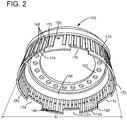
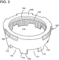
- FIGS. 1 and 2 show a bottom and side perspective view, respectively, of embodiments of a positioning tool 100 according to embodiments of the disclosure.
- positioning tool 100 may axially position insert 120 about drive shaft 110.
- Positioning tool 100 may include a circular body 140 having an inner surface 142 configured to slide over an outer surface 128 ( FIG. 1 ) of drive shaft 110.
- Inner surface 142 has an inner diameter ID ( FIG. 2 ) configured to slide over an outer diameter OD ( FIG. 1 ) of outer surface 128.
- Positioning tool 100 may also include a plurality of splines 146 on inner surface 142 of circular body 140.
- Splines 146 are configured to mate with splines 126 on outer surface 128 of drive shaft 110. That is, splines 146 may axially slide within spaces between splines 126, and vice versa, during axial movement of positioning tool 100 over drive shaft 110. Consequently, positioning tool 100 and drive shaft 110 are circumferentially coupled when splines 126, 146 interlock.
- FIG. 2 shows an embodiment in which positioning tool 100 includes splines 148 on an outer surface 150 thereof, while FIG. 3 shows positioning tool 100 with a smooth outer surface. Splines 148 are optional, and do not serve any purpose other than perhaps ease of handling of positioning tool 100.
- Positioning tool 100 may also include a depth setting member 160 positioned on circular body 140.
- Depth setting member 160 may define an axial extent to which circular body 140 slides over outer surface 128 of drive shaft 110.
- Depth setting member 160 can take the form of any structure that can set the axial extent to which circular body 140 slides over outer surface 128.
- depth setting member 160 includes a ledge 162 that extends radially inward from circular body 140 so as to abut an axial end 164 of drive shaft 110 when positioning tool 100 is slid thereover. It will be recognized that depth setting member 160 may include any form of structure on positioning tool 100 that can contact axial end 164 or other structure on drive shaft 110 to define an axial position of positioning tool 100 relative to drive shaft 110.
- Positioning tool 100 may also include a position setting element 170 extending axially from circular body 140.
- Position setting element 170 is configured to contact an axial end 172 ( FIG. 1 ) of insert 120 to axially position insert 120 about drive shaft 110.
- Position setting element 170 may include any element on or part of circular body 140 capable of contacting axial end 172 of insert 120. Any number of position setting elements 170 may be used. As shown best in FIGS. 2 and 3 , each position setting element 170, i.e., an axial end thereof, has a predefined axial distance from depth setting member 160 that defines the proper axial position of axial end 172 of the insert, thus allowing proper axial positioning of insert 120 when axial end 172 abuts position setting element(s) 170.
- position setting element 170 may define an axial opening 174 therein to receive any circumferential positioning element(s) 124 extending axially from axial end 172 of insert 120.
- Each axial opening 174 may extend circumferentially about circular body 140 to any extent required to allow space for circumferential positioning element(s) 124.
- Any number of position setting element(s) 170 and axial openings 174 may be employed.
- position setting element 170 may include a plurality of position setting elements 170 arranged in a circumferentially spaced manner about circular body 140 to define a plurality of circumferentially spaced axial openings 174.
- a circumferential positioning element(s) 124 extending axially from axial end 172 of insert 120 may be positioned in each respective axial opening 174 such that circumferential positioning element(s) 124 may circumferentially position each respective axial opening 174.
- Positioning tool 100 may be made of a metal, e.g., a pure metal or metal alloy.
- the metal may include, for example, aluminum, nickel, or any other rigid metal.
- circular body 140, any optional splines 148 and depth setting member 160 are a unitary metal element, which can be made as a unitary element or may be made with a number components welded together.
- positioning tool 100 is shown as a single unitary piece of plastic. Positioning tool 100 may be made using any now known methods, e.g., casting, machining, welding, additive manufacture, etc.
- FIGS. 4-9 a method of positioning insert 120 on drive shaft 110 will now be described.
- the method may include positioning the positioning tool 100 on drive shaft 110 and positioning insert 120 about drive shaft 110. These two operations can happen in any order.
- the process may be carried out with drive shaft 110 positioned in gear box 112, or separate therefrom.
- FIG. 4 shows a side view of positioning insert 120 about drive shaft 110
- FIG. 5 shows a side view of initial positioning of positioning tool 100 on drive shaft 110, according to embodiments of the disclosure.
- insert 120 may be forcibly axially slid over axial end 164 of drive shaft 110 or, where a split 136 is provided therein, it may be temporarily expanded, and placed about a circumference of drive shaft 110.
- Insert 120 may be positioned in a location close to its desired final axial position. Where desired, insert 120 may be optionally temporarily fastened together and/or in place, e.g., with tape 180 ( FIG. 4 ), plastic ties 188 ( FIG. 8 ) or other temporary fastening mechanism. In the FIG. 4 example, insert 120 does not include circumferential positioning elements 124. In the FIG. 5 example, insert 120 includes circumferential positioning elements 124, which are positioned in splines 126, i.e., spaces between splines 126 to circumferentially position insert 120.
- the insert positioning may further include circumferentially positioning, i.e., by rotating insert 120, circumferential positioning element(s) 124 that extend axially from axial end 172 of insert 120 in a respective one of splines 126 on drive shaft 110, i.e., spaces therebetween.
- position setting element 170 includes axial opening 174 therein configured to receive circumferential positioning element(s) 124 on insert 120.
- FIG. 5 shows initial positioning of positioning tool 100 on drive shaft 110.
- Positioning tool 100 is aligned over drive shaft 110 and forced axially thereover, i.e., with a force F1.
- splines 146 on inner surface 142 are circumferentially positioned to mate with splines 126 on outer surface 128 of drive shaft 110.
- axial openings 174 in positioning tool 100 can be rotatably positioned to receive circumferential positioning elements 124 extending axially from insert 120 toward positioning tool 100.
- positioning tool 100 can be further axially slid onto drive shaft 110 such that splines 126, 146 engage.
- insert 120 While insert 120 is circumferentially located, it may not be properly axially positioned. Any circumferential positioning elements 124 provided can slide axially in splines 126, leaving insert axially mis-positioned.
- FIG. 6 shows a side view and FIG. 7 shows an enlarged side view of positioning tool 100 positioning insert 120 on drive shaft 110.
- positioning tool 100 As shown in FIG. 6 , as positioning tool 100 is further positioned, it continues to slide until depth setting member 160 ( FIGS. 2-3 ) contacts axial end 164 ( FIG. 1 ) of drive shaft 110. In this location, position setting elements 170 are axially in a location at which axial end 172 of insert 120 is to be positioned. A user ensures axial end 172 of insert 120 abuts position setting element 170 on positioning tool 100. Where positioning tool 100 is fully on drive shaft 110, this may occur by forcing axial end 172 of insert 120 against positioning tool 100.
- positioning tool 100 may be further axially slid until depth setting member 160 ( FIGS. 2-3 ) contacts axial end 164 ( FIG. 1 ), and/or axial end 172 of insert 120 may be slid until it abuts position setting element(s) 170 and then depth setting member 160 ( FIGS. 2-3 ) contacts axial end 164 ( FIG. 1 ).
- positioning tool 100 is positioned such that depth setting member 160 is against axial end 164 ( FIG. 1 ) of drive shaft 110, and axial end 172 of insert 120 is abuts position setting element(s) 170, thus properly positioning insert 120.
- FIG. 7 also shows arrows indicating removal of positioning tool 100 from drive shaft 110.
- Positioning tool 100 may be removed by axially pulling, i.e., with a force F2, positioning tool 100 off of drive shaft 110.
- insert 120 may be temporarily or permanently fastened in position.
- insert 120 is temporarily fastened to drive shaft 110.
- a distance D2 between axial end 172 of insert 120 and splines 126, i.e., an axial proximate end of splines 126 on drive shaft 110 may be measured to verify a position of insert 120. That is, to verify a desired axial position of insert 120 relative to splines 126 prior to fastening in that location.
- insert 120 may be temporarily fixed in a location, e.g., by tape, adhesive, and/or fasteners such as plastic ties 188 (shown).
- distance D2 between axial end 172 of insert 120 and splines 126 on drive shaft 110 may be measured after permanently fastening insert 120 to drive shaft 110, i.e., to verify a permanent position of insert 120 in a desired axial position thereof relative to splines 126.
- the measurements can be performed before or after removing positioning tool 100. In any event, the measurement can be carried out using any now known or later developed measurement tool having the desired accuracy, e.g., gauged calipers, measuring tape, optical measurement system, etc.
- axial end 172 of insert 120 is between 0.457 centimeters (cm) and 0.559 cm (0.180-0.220 inches) from splines 126.
- FIG. 9 shows a side view of permanently fastening insert 120 to drive shaft 110.
- the permanent fastening can occur in a number of ways.
- insert 120 may be permanently fastened to drive shaft 110 using, for example, an industrial adhesive for a plastic insert 120 or spot welds for a metal insert 120, both indicated by reference numeral 190. It is noted that adhesive may be on insert 120 prior to its positioning on drive shaft 110, and use of positioning tool 100 may occur to position insert 120 in its desired axial location with adhesive already thereon.
- insert 120 may be temporarily fastened, as shown in FIG. 8 , in position with a temporary fastener, e.g., tape, adhesive, plastic ties 188 ( FIG. 8 ). Then, insert 120 may be permanently adhered to drive shaft 110, e.g., using an industrial adhesive for a plastic insert 120 or spot welds for a metal insert 120. Once complete, any temporary fastener may be removed.
- a temporary fastener e.g., tape, adhesive, plastic ties
- Positioning tool 100 and the related method disclosed provide a mechanism to ensure circular lubricant dam insert 120 is properly axially positioned on splined drive shaft 110 while not interfering with circumferential positioning of the insert by circumferential positioning elements 124 on the insert that interact with the splined drive shaft.
- Positioning tool 100 is easy and inexpensive to make, and operates relatively quickly.
- Approximating language may be applied to modify any quantitative representation that could permissibly vary without resulting in a change in the basic function to which it is related. Accordingly, a value modified by a term or terms, such as “about,” “approximately” and “substantially,” are not to be limited to the precise value specified. In at least some instances, the approximating language may correspond to the precision of an instrument for measuring the value.
- range limitations may be combined and/or interchanged, such ranges are identified and include all the sub-ranges contained therein unless context or language indicates otherwise. "Approximately” as applied to a particular value of a range applies to both values, and unless otherwise dependent on the precision of the instrument measuring the value, may indicate +/-10% of the stated value(s).
Landscapes
- Engineering & Computer Science (AREA)
- General Engineering & Computer Science (AREA)
- Mechanical Engineering (AREA)
- Ocean & Marine Engineering (AREA)
- Shafts, Cranks, Connecting Bars, And Related Bearings (AREA)
- General Details Of Gearings (AREA)
Abstract
Description
- The disclosure relates generally to machine fabrication, and more particularly, to a positioning tool for a circular lubricant dam insert, and a related method.
- Gear boxes include various shafts that require constant lubrication during operation. One approach to ensure proper lubrication is to provide a lubricant dam insert about one or more drive shafts in the gear box. The lubricant dam insert may be a plastic circular element that includes a number radial openings therein to retain and/or distribute lubricant, e.g., oil, to a particular location about the drive shaft. The circular lubricant dam insert may include axially extending positioning elements thereon to engage with splines on the drive shaft to circumferentially position the dam insert, but axial positioning can be challenging. Improper axial positioning can lead to poor lubrication and/or breaking of the insert.
- A first aspect of the disclosure provides a positioning tool for axially positioning a circular lubricant dam insert on a splined drive shaft, the positioning tool comprising: a circular body having an inner surface configured to slide over an outer surface of the splined drive shaft; a first plurality of splines on the inner surface of the circular body, the first plurality of splines configured to mate with a second plurality of splines on the outer surface of the splined drive shaft; a depth setting member positioned on the circular body, the depth setting member defining an axial extent to which the circular body slides over the outer surface of the splined drive shaft; and a position setting element extending axially from the circular body, the position setting element configured to contact an axial end of the circular lubricant dam insert to axially position the circular lubricant dam insert on the splined drive shaft.
- A second aspect of the disclosure provides a method of positioning a circular lubricant dam insert on a splined drive shaft, the method comprising: positioning a positioning tool on the splined drive shaft, the positioning tool including: a circular body having an inner surface configured to slide over an outer surface of the splined drive shaft, a first plurality of splines on the inner surface of the circular body, the first plurality of splines configured to axially mate with a second plurality of splines on the outer side of the splined drive shaft during the positioning, a depth setting member positioned on the circular body, the depth setting member defining an axial extent to which the circular body slides over the outer surface of the splined drive shaft during the positioning, and a position setting element extending axially from the circular body, the position setting element configured to contact and axially position the circular lubricant dam insert on the splined drive shaft; positioning the circular lubricant dam insert about the splined drive shaft, ensuring an axial end of the circular lubricant dam insert abuts the position setting element on the positioning tool; permanently fastening the circular lubricant dam insert to the splined drive shaft; and removing the positioning tool.
- The illustrative aspects of the present disclosure are designed to solve the problems herein described and/or other problems not discussed.
- These and other features of this disclosure will be more readily understood from the following detailed description of the various aspects of the disclosure taken in conjunction with the accompanying drawings that depict various embodiments of the disclosure, in which:
-
FIG. 1 shows a side exploded view of a circular lubricant dam insert and a splined drive shaft, according to embodiments of the disclosure. -
FIG. 2 shows a bottom perspective view of a positioning tool for the insert, according to embodiments of the disclosure. -
FIG. 3 shows a side perspective view of a positioning tool for the insert, according to other embodiments of the disclosure. -
FIG. 4 shows a side view of the circular lubricant dam insert on the splined drive shaft, according to embodiments of the disclosure. -
FIG. 5 shows a side view of initial positioning of the positioning tool on the drive shaft, according to embodiments of the disclosure. -
FIG. 6 shows a side view of the positioning tool positioning the insert on the drive shaft, according to embodiments of the disclosure. -
FIG. 7 shows an enlarged side view of the positioning tool positioning the insert on the drive shaft and arrows indicating removal of the positioning tool, according to embodiments of the disclosure. -
FIG. 8 shows a side view of the insert temporarily fastened on the drive shaft, according to embodiments of the disclosure. -
FIG. 9 shows a side view of the insert permanently fastened on the drive shaft, according to embodiments of the disclosure. - It is noted that the drawings of the disclosure are not to scale. The drawings are intended to depict only typical aspects of the disclosure, and therefore should not be considered as limiting the scope of the disclosure. In the drawings, like numbering represents like elements between the drawings.
- As an initial matter, in order to clearly describe the current disclosure it will become necessary to select certain terminology when referring to and describing relevant machine components within an illustrative application of a gear box. When doing this, if possible, common industry terminology will be used and employed in a manner consistent with its accepted meaning. Unless otherwise stated, such terminology should be given a broad interpretation consistent with the context of the present application and the scope of the appended claims. Those of ordinary skill in the art will appreciate that often a particular component may be referred to using several different or overlapping terms. What may be described herein as being a single part may include and be referenced in another context as consisting of multiple components. Alternatively, what may be described herein as including multiple components may be referred to elsewhere as a single part.
- In addition, several descriptive terms may be used regularly herein, and it should prove helpful to define these terms at the onset of this section. These terms and their definitions, unless stated otherwise, are as follows. It is often required to describe parts that are at differing radial positions with regard to a center axis. The term "radial" refers to movement or position perpendicular to an axis, e.g., of a drive shaft. In cases such as this, if a first component resides closer to the axis than a second component, it will be stated herein that the first component is "radially inward" or "inboard" of the second component. If, on the other hand, the first component resides further from the axis than the second component, it may be stated herein that the first component is "radially outward" or "outboard" of the second component. The term "axial" refers to movement or position parallel to an axis, e.g., along a drive shaft. Finally, the term "circumferential" refers to movement or position around an axis, e.g., around a drive shaft. It will be appreciated that such terms may be applied in relation to the center axis of the turbine.
- In addition, several descriptive terms may be used regularly herein, as described below. The terms "first," "second," and "third" may be used interchangeably to distinguish one component from another and are not intended to signify location or importance of the individual components.
- The terminology used herein is for the purpose of describing particular embodiments only and is not intended to be limiting of the disclosure. As used herein, the singular forms "a," "an," and "the" are intended to include the plural forms as well, unless the context clearly indicates otherwise. It will be further understood that the terms "comprises" and/or "comprising," when used in this specification, specify the presence of stated features, integers, steps, operations, elements, and/or components, but do not preclude the presence or addition of one or more other features, integers, steps, operations, elements, components, and/or groups thereof. "Optional" or "optionally" means that the subsequently described event or circumstance may or may not occur, and that the description includes instances where the event occurs and instances where it does not.
- Where an element or layer is referred to as being "on," "engaged to," "connected to" or "coupled to" another element or layer, it may be directly on, engaged, connected or coupled to the other element or layer, or intervening elements or layers may be present. In contrast, when an element is referred to as being "directly on," "directly engaged to," "directly connected to" or "directly coupled to" another element or layer, there may be no intervening elements or layers present. Other words used to describe the relationship between elements should be interpreted in a like fashion (e.g., "between" versus "directly between," "adjacent" versus "directly adjacent," etc.). As used herein, the term "and/or" includes any and all combinations of one or more of the associated listed items.
- As indicated above, the disclosure provides a positioning tool for axially positioning a circular lubricant dam insert on a splined drive shaft. The positioning tool ensures the insert is properly axially positioned on the splined drive shaft while not interfering with circumferential positioning of the insert by circumferential positioning elements on the insert that interact with the splined drive shaft.
-
FIG. 1 shows a side exploded view of asplined drive shaft 110 and a circular lubricant dam insert 120 in an illustrative application within agear box 112.Gear box 112 may include any now known or later developed transmission system including acasing 122 and transfer gears (not shown) therein. As understood, splineddrive shaft 110 may be powered to drive one or more other gears (not shown) to transfer rotating power in a direction different thandrive shaft 110, e.g., perpendicular to the drive shaft. Casing 122 is sealed to enclosesplined drive shaft 110 and other gears, and to provide a lubricant reservoir about the drive shaft and gears. Splineddrive shaft 110 may have a circular cross-section; although that may not be necessary in all cases. Splineddrive shaft 110 includes a plurality ofsplines 126 on anouter surface 128 thereof.Splines 126 may interact with gears (not shown) ingear box 112 to transmit power. While shown in the illustrative application of a gear box, it is recognized that the teachings of the disclosure may be applied to any application in which a circularlubricant dam insert 120 is axially positioned on asplined drive shaft 110. - Circular lubricant dam insert 120 (hereinafter "insert 120") may include any now known or later developed element configured to receive a lubricant, e.g., oil or other lubricating liquid or gas, and to retain and/or distribute the lubricant to a desired location about splined drive shaft 110 (hereinafter "
drive shaft 110"). Insert 120 may take any form of circular lubricant dam. In the example shown,insert 120 includes acircular member 130 that is cylindrical, and includes a number of radially extendingopenings 132 therein. When positioned againstdrive shaft 110, radially extendingopenings 132 act as lubricant reservoirs. As illustrated,openings 132 may be angled circumferentially to direct lubricant where desired, and may includelubricant passages 134 therein to further direct lubricant where desired, e.g., to splines 126.Insert 120 may made of, for example, a flexible metal or plastic.Insert 120 may include anaxial split 136 therein allowing radial expansion and positioning thereof aboutdrive shaft 110, but this may not be necessary in all cases.Insert 120 may optionally include acircumferential positioning element 124 extending axially from anaxial end 172 ofinsert 120. Circumferential positioning element(s) 124 may seat in arespective spline 126, i.e., spaces between one ormore splines 126 ofdrive shaft 110, to circumferentially position insert 120 relative to driveshaft 110. Any number ofcircumferential positioning elements 124 may be employed aboutdrive shaft 110, or none can be used (see e.g.,FIG. 5 ). While shown in pairs, they may be in other numbered sets. As understood on the art, insert 120 is axially positioned aboutdrive shaft 110 to provide lubricant where desired. For example, insert 120 may be axially positioned just belowsplines 126 ofdrive shaft 110 to ensure lubricant is delivered in a consistent manner tosplines 126 and/or any gears that interact therewith. Proper axial positioning ofinsert 120 aids lubrication and prevents damage to the insert and other structure. -
FIGS. 1 and2 show a bottom and side perspective view, respectively, of embodiments of apositioning tool 100 according to embodiments of the disclosure. As will be described,positioning tool 100 may axially position insert 120 aboutdrive shaft 110.Positioning tool 100 may include acircular body 140 having aninner surface 142 configured to slide over an outer surface 128 (FIG. 1 ) ofdrive shaft 110.Inner surface 142 has an inner diameter ID (FIG. 2 ) configured to slide over an outer diameter OD (FIG. 1 ) ofouter surface 128. -
Positioning tool 100 may also include a plurality ofsplines 146 oninner surface 142 ofcircular body 140.Splines 146 are configured to mate withsplines 126 onouter surface 128 ofdrive shaft 110. That is, splines 146 may axially slide within spaces betweensplines 126, and vice versa, during axial movement ofpositioning tool 100 overdrive shaft 110. Consequently,positioning tool 100 and driveshaft 110 are circumferentially coupled whensplines FIG. 2 shows an embodiment in whichpositioning tool 100 includessplines 148 on anouter surface 150 thereof, whileFIG. 3 showspositioning tool 100 with a smooth outer surface.Splines 148 are optional, and do not serve any purpose other than perhaps ease of handling ofpositioning tool 100. -
Positioning tool 100 may also include adepth setting member 160 positioned oncircular body 140.Depth setting member 160 may define an axial extent to whichcircular body 140 slides overouter surface 128 ofdrive shaft 110.Depth setting member 160 can take the form of any structure that can set the axial extent to whichcircular body 140 slides overouter surface 128. InFIGS. 2 and3 ,depth setting member 160 includes aledge 162 that extends radially inward fromcircular body 140 so as to abut anaxial end 164 ofdrive shaft 110 when positioningtool 100 is slid thereover. It will be recognized thatdepth setting member 160 may include any form of structure onpositioning tool 100 that can contactaxial end 164 or other structure ondrive shaft 110 to define an axial position ofpositioning tool 100 relative to driveshaft 110. -
Positioning tool 100 may also include aposition setting element 170 extending axially fromcircular body 140.Position setting element 170 is configured to contact an axial end 172 (FIG. 1 ) ofinsert 120 to axially position insert 120 aboutdrive shaft 110.Position setting element 170 may include any element on or part ofcircular body 140 capable of contactingaxial end 172 ofinsert 120. Any number ofposition setting elements 170 may be used. As shown best inFIGS. 2 and3 , eachposition setting element 170, i.e., an axial end thereof, has a predefined axial distance fromdepth setting member 160 that defines the proper axial position ofaxial end 172 of the insert, thus allowing proper axial positioning ofinsert 120 whenaxial end 172 abuts position setting element(s) 170. - As will be described in greater detail herein,
position setting element 170 may define anaxial opening 174 therein to receive any circumferential positioning element(s) 124 extending axially fromaxial end 172 ofinsert 120. Eachaxial opening 174 may extend circumferentially aboutcircular body 140 to any extent required to allow space for circumferential positioning element(s) 124. Any number of position setting element(s) 170 andaxial openings 174 may be employed. In this fashion,position setting element 170 may include a plurality ofposition setting elements 170 arranged in a circumferentially spaced manner aboutcircular body 140 to define a plurality of circumferentially spacedaxial openings 174. A circumferential positioning element(s) 124 extending axially fromaxial end 172 ofinsert 120 may be positioned in each respectiveaxial opening 174 such that circumferential positioning element(s) 124 may circumferentially position each respectiveaxial opening 174. -
Positioning tool 100 may be made of a metal, e.g., a pure metal or metal alloy. The metal may include, for example, aluminum, nickel, or any other rigid metal. InFIG. 2 ,circular body 140, anyoptional splines 148 anddepth setting member 160 are a unitary metal element, which can be made as a unitary element or may be made with a number components welded together. InFIG. 3 ,positioning tool 100 is shown as a single unitary piece of plastic.Positioning tool 100 may be made using any now known methods, e.g., casting, machining, welding, additive manufacture, etc. - Turning to
FIGS. 4-9 , a method ofpositioning insert 120 ondrive shaft 110 will now be described. The method may include positioning thepositioning tool 100 ondrive shaft 110 andpositioning insert 120 aboutdrive shaft 110. These two operations can happen in any order. The process may be carried out withdrive shaft 110 positioned ingear box 112, or separate therefrom.FIG. 4 shows a side view ofpositioning insert 120 aboutdrive shaft 110, andFIG. 5 shows a side view of initial positioning ofpositioning tool 100 ondrive shaft 110, according to embodiments of the disclosure. Here, insert 120 may be forcibly axially slid overaxial end 164 ofdrive shaft 110 or, where asplit 136 is provided therein, it may be temporarily expanded, and placed about a circumference ofdrive shaft 110.Insert 120 may be positioned in a location close to its desired final axial position. Where desired, insert 120 may be optionally temporarily fastened together and/or in place, e.g., with tape 180 (FIG. 4 ), plastic ties 188 (FIG. 8 ) or other temporary fastening mechanism. In theFIG. 4 example, insert 120 does not includecircumferential positioning elements 124. In theFIG. 5 example, insert 120 includescircumferential positioning elements 124, which are positioned insplines 126, i.e., spaces betweensplines 126 tocircumferentially position insert 120. In this setting, the insert positioning may further include circumferentially positioning, i.e., by rotatinginsert 120, circumferential positioning element(s) 124 that extend axially fromaxial end 172 ofinsert 120 in a respective one ofsplines 126 ondrive shaft 110, i.e., spaces therebetween. As noted,position setting element 170 includesaxial opening 174 therein configured to receive circumferential positioning element(s) 124 oninsert 120. - As noted,
FIG. 5 shows initial positioning ofpositioning tool 100 ondrive shaft 110.Positioning tool 100 is aligned overdrive shaft 110 and forced axially thereover, i.e., with a force F1. Referring toFIG. 2 , splines 146 oninner surface 142 are circumferentially positioned to mate withsplines 126 onouter surface 128 ofdrive shaft 110. By circumferentially positioning, i.e., rotating,positioning tool 100 aboutdrive shaft 110 prior to engagement ofsplines axial openings 174 inpositioning tool 100 can be rotatably positioned to receivecircumferential positioning elements 124 extending axially frominsert 120 towardpositioning tool 100. Once in the desired rotational location, positioningtool 100 can be further axially slid ontodrive shaft 110 such that splines 126, 146 engage. At this point, whileinsert 120 is circumferentially located, it may not be properly axially positioned. Anycircumferential positioning elements 124 provided can slide axially insplines 126, leaving insert axially mis-positioned. -
FIG. 6 shows a side view andFIG. 7 shows an enlarged side view ofpositioning tool 100positioning insert 120 ondrive shaft 110. As shown inFIG. 6 , aspositioning tool 100 is further positioned, it continues to slide until depth setting member 160 (FIGS. 2-3 ) contacts axial end 164 (FIG. 1 ) ofdrive shaft 110. In this location,position setting elements 170 are axially in a location at whichaxial end 172 ofinsert 120 is to be positioned. A user ensuresaxial end 172 ofinsert 120 abutsposition setting element 170 onpositioning tool 100. Wherepositioning tool 100 is fully ondrive shaft 110, this may occur by forcingaxial end 172 ofinsert 120 againstpositioning tool 100. Similarly, wherepositioning tool 100 is not fully ondrive shaft 110, it may be further axially slid until depth setting member 160 (FIGS. 2-3 ) contacts axial end 164 (FIG. 1 ), and/oraxial end 172 ofinsert 120 may be slid until it abuts position setting element(s) 170 and then depth setting member 160 (FIGS. 2-3 ) contacts axial end 164 (FIG. 1 ). In any regard,positioning tool 100 is positioned such thatdepth setting member 160 is against axial end 164 (FIG. 1 ) ofdrive shaft 110, andaxial end 172 ofinsert 120 is abuts position setting element(s) 170, thus properly positioninginsert 120. - At this point, a number of different operations can occur including: permanently fastening
insert 120 to driveshaft 110, verifying an axial position ofinsert 120, and/or removingpositioning tool 100. The order in which these steps occur can be user-defined. -
FIG. 7 also shows arrows indicating removal ofpositioning tool 100 fromdrive shaft 110.Positioning tool 100 may be removed by axially pulling, i.e., with a force F2,positioning tool 100 off ofdrive shaft 110. At this point, insert 120 may be temporarily or permanently fastened in position. - In one embodiment, as shown in the side view of
FIG. 8 , insert 120 is temporarily fastened to driveshaft 110. Here, prior to permanently fasteninginsert 120 to driveshaft 110, a distance D2 betweenaxial end 172 ofinsert 120 andsplines 126, i.e., an axial proximate end ofsplines 126 ondrive shaft 110, may be measured to verify a position ofinsert 120. That is, to verify a desired axial position ofinsert 120 relative tosplines 126 prior to fastening in that location. Here, insert 120 may be temporarily fixed in a location, e.g., by tape, adhesive, and/or fasteners such as plastic ties 188 (shown). In another embodiment, distance D2 betweenaxial end 172 ofinsert 120 andsplines 126 ondrive shaft 110 may be measured after permanently fasteninginsert 120 to driveshaft 110, i.e., to verify a permanent position ofinsert 120 in a desired axial position thereof relative to splines 126. The measurements can be performed before or after removingpositioning tool 100. In any event, the measurement can be carried out using any now known or later developed measurement tool having the desired accuracy, e.g., gauged calipers, measuring tape, optical measurement system, etc. In one non-limiting example,axial end 172 ofinsert 120 is between 0.457 centimeters (cm) and 0.559 cm (0.180-0.220 inches) fromsplines 126. -
FIG. 9 shows a side view of permanently fasteninginsert 120 to driveshaft 110. The permanent fastening can occur in a number of ways. In one example, insert 120 may be permanently fastened to driveshaft 110 using, for example, an industrial adhesive for aplastic insert 120 or spot welds for ametal insert 120, both indicated byreference numeral 190. It is noted that adhesive may be oninsert 120 prior to its positioning ondrive shaft 110, and use ofpositioning tool 100 may occur to position insert 120 in its desired axial location with adhesive already thereon. In another example, insert 120 may be temporarily fastened, as shown inFIG. 8 , in position with a temporary fastener, e.g., tape, adhesive, plastic ties 188 (FIG. 8 ). Then, insert 120 may be permanently adhered to driveshaft 110, e.g., using an industrial adhesive for aplastic insert 120 or spot welds for ametal insert 120. Once complete, any temporary fastener may be removed. -
Positioning tool 100 and the related method disclosed provide a mechanism to ensure circularlubricant dam insert 120 is properly axially positioned onsplined drive shaft 110 while not interfering with circumferential positioning of the insert bycircumferential positioning elements 124 on the insert that interact with the splined drive shaft.Positioning tool 100 is easy and inexpensive to make, and operates relatively quickly. - The foregoing drawings show some of the processing associated according to several embodiments of this disclosure. In this regard, each drawing may represent a process associated with embodiments of the method described. It should also be noted that in some alternative implementations, the acts noted in the drawings may occur out of the order noted in the figure or, for example, may in fact be executed substantially concurrently or in the reverse order, depending upon the act involved.
- Approximating language, as used herein throughout the specification and claims, may be applied to modify any quantitative representation that could permissibly vary without resulting in a change in the basic function to which it is related. Accordingly, a value modified by a term or terms, such as "about," "approximately" and "substantially," are not to be limited to the precise value specified. In at least some instances, the approximating language may correspond to the precision of an instrument for measuring the value. Here and throughout the specification and claims, range limitations may be combined and/or interchanged, such ranges are identified and include all the sub-ranges contained therein unless context or language indicates otherwise. "Approximately" as applied to a particular value of a range applies to both values, and unless otherwise dependent on the precision of the instrument measuring the value, may indicate +/-10% of the stated value(s).
- The corresponding structures, materials, acts, and equivalents of all means or step plus function elements in the claims below are intended to include any structure, material, or act for performing the function in combination with other claimed elements as specifically claimed. The description of the present disclosure has been presented for purposes of illustration and description, but is not intended to be exhaustive or limited to the disclosure in the form disclosed. Many modifications and variations will be apparent to those of ordinary skill in the art without departing from the scope and spirit of the disclosure. The embodiment was chosen and described in order to best explain the principles of the disclosure and the practical application, and to enable others of ordinary skill in the art to understand the disclosure for various embodiments with various modifications as are suited to the particular use contemplated.
Claims (12)
- A positioning tool (100) for axially positioning a circular lubricant dam insert (120) on a splined drive shaft (110), the positioning tool (100) comprising:a circular body (140) having an inner surface (142) configured to slide over an outer surface (128, 150) of the splined drive shaft (110);a first plurality of splines (126, 146, 148) on the inner surface (142) of the circular body (140), the first plurality of splines (126, 146, 148) configured to mate with a second plurality of splines (126, 146, 148) on the outer surface (128, 150) of the splined drive shaft (110);a depth setting member (160) positioned on the circular body (140), the depth setting member (160) defining an axial extent to which the circular body (140) slides over the outer surface (128, 150) of the splined drive shaft (110); anda position setting element (170) extending axially from the circular body (140), the position setting element (170) configured to contact an axial end (164, 172) of the circular lubricant dam insert (120) to axially position the circular lubricant dam insert (120) on the splined drive shaft (110).
- The positioning tool (100) of claim 1, wherein the circular body (140), the first plurality of splines (126, 146, 148) and the depth setting member (160) are a unitary metal element.
- The positioning tool (100) of claim 1, wherein the position setting element (170) defines an axial opening (174) therein to receive a circumferential positioning element (124) extending axially from the axial end (164, 172) of the circular lubricant dam insert (120), the circumferential positioning element (124) configured to seat in a respective spline (126, 146, 148) of the second plurality of splines (126, 146, 148) on the splined drive shaft (110) to circumferentially position the circular lubricant dam insert (120).
- The positioning tool (100) of claim 3, wherein the position setting element (170) includes a plurality of position setting elements (170) arranged in a circumferentially spaced manner about the circular body (140) to define a plurality of circumferentially spaced axial openings (174), and wherein the circular lubricant dam insert (120) includes a circumferential positioning element (124) extending axially from the axial end (164, 172) thereof for positioning in each respective axial opening (174).
- The positioning tool (100) of claim 1, wherein the splined drive shaft (110) is positioned in a gear box (112).
- A method of positioning a circular lubricant dam insert (120) on a splined drive shaft (110), the method comprising:positioning a positioning tool (100) on the splined drive shaft (110), the positioning tool (100) including:a circular body (140) having an inner surface (142) configured to slide over an outer surface (128, 150) of the splined drive shaft (110),a first plurality of splines (126, 146, 148) on the inner surface (142) of the circular body (140), the first plurality of splines (126, 146, 148) configured to axially mate with a second plurality of splines (126, 146, 148) on the outer surface (128, 150) of the splined drive shaft (110) during the positioning,a depth setting member (160) positioned on the circular body (140), the depth setting member (160) defining an axial extent to which the circular body (140) slides over the outer surface (128, 150) of the splined drive shaft (110) during the positioning, anda position setting element (170) extending axially from the circular body (140), the position setting element (170) configured to contact and axially position the circular lubricant dam insert (120) on the splined drive shaft (110);positioning the circular lubricant dam insert (120) about the splined drive shaft (110), ensuring an axial end (164, 172) of the circular lubricant dam insert (120) abuts the position setting element (170) on the positioning tool (100);permanently fastening the circular lubricant dam insert (120) to the splined drive shaft (110); andremoving the positioning tool (100).
- The method of claim 6, wherein the circular lubricant dam insert (120) positioning further includes circumferentially positioning a circumferential positioning element (124) extending axially from the axial end (164, 172) of the circular lubricant dam insert (120) in a respective one of the second plurality of splines (126, 146, 148) on the splined drive shaft (110), wherein the position setting element (170) includes an axial opening (174) therein configured to receive the circumferential positioning element (124).
- The method of claim 6, further comprising, prior to permanently fastening the circular lubricant dam insert (120), measuring a distance between the axial end (164, 172) of the circular lubricant dam insert (120) and the second plurality of splines (126, 146, 148) on the splined drive shaft (110) to verify a position of the circular lubricant dam insert (120).
- The method of claim 6, further comprising, after permanently fastening the circular lubricant dam insert (120), measuring a distance between the axial end (164, 172) of the circular lubricant dam insert (120) and the second plurality of splines (126, 146, 148) on the splined drive shaft (110) to verify a position of the circular lubricant dam insert (120).
- The method of claim 6, wherein the permanently fastening includes:temporarily fastening the circular lubricant dam insert (120) in position with a temporary fastener;permanently adhering the circular lubricant dam insert (120) to the splined drive shaft (110); andremoving the temporary fastener.
- The method of claim 6, further comprising, after removing the positioning tool (100), measuring a distance between the axial end (164, 172) of the circular lubricant dam insert (120) and the second plurality of splines (126, 146, 148) on the splined drive shaft (110) to verify a position of the circular lubricant dam insert (120).
- The method of claim 6, wherein the splined drive shaft (110) is positioned in a gear box (112).
Applications Claiming Priority (1)
| Application Number | Priority Date | Filing Date | Title |
|---|---|---|---|
| US16/701,414 US11454274B2 (en) | 2019-12-03 | 2019-12-03 | Positioning tool for circular lubricant dam insert, and related method |
Publications (2)
| Publication Number | Publication Date |
|---|---|
| EP3831535A1 true EP3831535A1 (en) | 2021-06-09 |
| EP3831535B1 EP3831535B1 (en) | 2023-06-28 |
Family
ID=73029971
Family Applications (1)
| Application Number | Title | Priority Date | Filing Date |
|---|---|---|---|
| EP20204206.5A Active EP3831535B1 (en) | 2019-12-03 | 2020-10-27 | Positioning tool for circular lubricant dam insert, and related method |
Country Status (4)
| Country | Link |
|---|---|
| US (1) | US11454274B2 (en) |
| EP (1) | EP3831535B1 (en) |
| JP (1) | JP7589014B2 (en) |
| CN (1) | CN112901757B (en) |
Citations (1)
| Publication number | Priority date | Publication date | Assignee | Title |
|---|---|---|---|---|
| DE102009038292A1 (en) * | 2009-02-04 | 2010-08-12 | Sew-Eurodrive Gmbh & Co. Kg | Gear i.e. bevel gear, has clutch comprising tappet as coupling part that is connected with toothed wheel in torque-proof and detachable manner, where tappet is connected with shaft and arranged on shaft in axially displaceable manner |
Family Cites Families (11)
| Publication number | Priority date | Publication date | Assignee | Title |
|---|---|---|---|---|
| US3110095A (en) * | 1961-03-17 | 1963-11-12 | Federal Mogul Bower Bearings | Method of installing a shaft seal within a housing |
| US3197216A (en) * | 1962-07-31 | 1965-07-27 | Homer E Jackson | Alignment control and seal for spline drives |
| US4126317A (en) * | 1976-05-24 | 1978-11-21 | Garlock Inc. | Seal for installing seal over splined shaft |
| US4218813A (en) * | 1979-01-31 | 1980-08-26 | Garlock Inc. | Method and tool for installing shafts through seals |
| US4815884A (en) * | 1988-05-23 | 1989-03-28 | General Motors Corporation | Removable seal protector and shaft insertion guide |
| JP2001090818A (en) | 1999-09-22 | 2001-04-03 | Ishikawajima Harima Heavy Ind Co Ltd | Spline lubrication structure |
| FR2850136B1 (en) * | 2003-01-21 | 2006-05-26 | Valeo Equip Electr Moteur | METHOD FOR MOUNTING A STOP RING ON AN ELECTRIC STARTER SHAFT PROVIDED WITH A LAUNCHER WITH STOP ON CANNELURES |
| JP6011973B2 (en) | 2013-03-05 | 2016-10-25 | 本田技研工業株式会社 | Bearing detent structure in transmission |
| US9382997B2 (en) * | 2014-07-24 | 2016-07-05 | Deere & Company | Gear set lubrication system and method |
| FR3059753B1 (en) * | 2016-12-02 | 2019-10-25 | Renault S.A.S | LUBRICATING OIL GUIDING DEVICE WITHIN A HOLLOW GEARBOX SHAFT |
| JP6687660B2 (en) * | 2018-03-27 | 2020-04-28 | ファナック株式会社 | Seal mounting device and seal mounting method |
-
2019
- 2019-12-03 US US16/701,414 patent/US11454274B2/en active Active
-
2020
- 2020-10-19 CN CN202011119754.0A patent/CN112901757B/en active Active
- 2020-10-27 EP EP20204206.5A patent/EP3831535B1/en active Active
- 2020-11-04 JP JP2020184657A patent/JP7589014B2/en active Active
Patent Citations (1)
| Publication number | Priority date | Publication date | Assignee | Title |
|---|---|---|---|---|
| DE102009038292A1 (en) * | 2009-02-04 | 2010-08-12 | Sew-Eurodrive Gmbh & Co. Kg | Gear i.e. bevel gear, has clutch comprising tappet as coupling part that is connected with toothed wheel in torque-proof and detachable manner, where tappet is connected with shaft and arranged on shaft in axially displaceable manner |
Also Published As
| Publication number | Publication date |
|---|---|
| CN112901757A (en) | 2021-06-04 |
| EP3831535B1 (en) | 2023-06-28 |
| US11454274B2 (en) | 2022-09-27 |
| US20210164514A1 (en) | 2021-06-03 |
| JP7589014B2 (en) | 2024-11-25 |
| JP2021089068A (en) | 2021-06-10 |
| CN112901757B (en) | 2025-06-03 |
Similar Documents
| Publication | Publication Date | Title |
|---|---|---|
| EP2352622B1 (en) | Disc-shaped torque transducer | |
| US7878059B2 (en) | Axle assembly with sensor assembly | |
| EP0891494B1 (en) | Annular shaft flange | |
| US7896748B2 (en) | Coupling apparatus | |
| EP2711575A1 (en) | Rotation transmitting apparatus, vehicle steering system, and intermediate shaft | |
| US11454274B2 (en) | Positioning tool for circular lubricant dam insert, and related method | |
| US7296976B2 (en) | Dual counterweight balancing system | |
| EP3434417B1 (en) | Drive guide | |
| US1935678A (en) | Clutch gauge | |
| EP0020517B1 (en) | Expandable arbor for holding a stack of elements | |
| US20180073569A1 (en) | Universal damper and interchangeable hub assembly | |
| WO2013006604A2 (en) | Weldment with isolation pocket for reduction of weld-induced distortion | |
| SE530385C2 (en) | Tool for mounting and / or disassembling spiral-wound wire without pin | |
| CN109964056B (en) | Improvements to the clutch | |
| EP1900954A1 (en) | Gearwheel unit, transmission having gearwheel unit and gearwheel manufacturing method | |
| KR20210142181A (en) | Transmission housing and differential | |
| US10274303B2 (en) | Major diameter total runout gage for an external spline | |
| JP5960266B2 (en) | Electromagnetic clutch mounting structure of phase variable device in engine, electromagnetic clutch removing method, and electromagnetic clutch removing jig | |
| US8371012B2 (en) | Drill press cutter | |
| CN111272339B (en) | Clutch outer sleeve assembly balancing method and overrunning clutch assembling method | |
| EP1936221A2 (en) | Friction clutch particularly for motorcycles | |
| JP6227987B2 (en) | Jig for assembling driving device for vehicle and method for assembling driving device for vehicle using this jig | |
| GB2517429A (en) | Method and apparatus for aligning engine and transmission | |
| JP2022124417A (en) | Sleeve positioning fixing tool, positioning method and positioning tool | |
| EP3808505A1 (en) | Insertion tool |
Legal Events
| Date | Code | Title | Description |
|---|---|---|---|
| PUAI | Public reference made under article 153(3) epc to a published international application that has entered the european phase |
Free format text: ORIGINAL CODE: 0009012 |
|
| STAA | Information on the status of an ep patent application or granted ep patent |
Free format text: STATUS: THE APPLICATION HAS BEEN PUBLISHED |
|
| AK | Designated contracting states |
Kind code of ref document: A1 Designated state(s): AL AT BE BG CH CY CZ DE DK EE ES FI FR GB GR HR HU IE IS IT LI LT LU LV MC MK MT NL NO PL PT RO RS SE SI SK SM TR |
|
| STAA | Information on the status of an ep patent application or granted ep patent |
Free format text: STATUS: REQUEST FOR EXAMINATION WAS MADE |
|
| 17P | Request for examination filed |
Effective date: 20211130 |
|
| RBV | Designated contracting states (corrected) |
Designated state(s): AL AT BE BG CH CY CZ DE DK EE ES FI FR GB GR HR HU IE IS IT LI LT LU LV MC MK MT NL NO PL PT RO RS SE SI SK SM TR |
|
| GRAP | Despatch of communication of intention to grant a patent |
Free format text: ORIGINAL CODE: EPIDOSNIGR1 |
|
| STAA | Information on the status of an ep patent application or granted ep patent |
Free format text: STATUS: GRANT OF PATENT IS INTENDED |
|
| RIC1 | Information provided on ipc code assigned before grant |
Ipc: B25B 27/28 20060101AFI20230220BHEP |
|
| INTG | Intention to grant announced |
Effective date: 20230324 |
|
| GRAS | Grant fee paid |
Free format text: ORIGINAL CODE: EPIDOSNIGR3 |
|
| GRAA | (expected) grant |
Free format text: ORIGINAL CODE: 0009210 |
|
| STAA | Information on the status of an ep patent application or granted ep patent |
Free format text: STATUS: THE PATENT HAS BEEN GRANTED |
|
| AK | Designated contracting states |
Kind code of ref document: B1 Designated state(s): AL AT BE BG CH CY CZ DE DK EE ES FI FR GB GR HR HU IE IS IT LI LT LU LV MC MK MT NL NO PL PT RO RS SE SI SK SM TR |
|
| REG | Reference to a national code |
Ref country code: CH Ref legal event code: EP |
|
| REG | Reference to a national code |
Ref country code: AT Ref legal event code: REF Ref document number: 1582287 Country of ref document: AT Kind code of ref document: T Effective date: 20230715 |
|
| REG | Reference to a national code |
Ref country code: IE Ref legal event code: FG4D |
|
| REG | Reference to a national code |
Ref country code: DE Ref legal event code: R096 Ref document number: 602020012964 Country of ref document: DE |
|
| REG | Reference to a national code |
Ref country code: LT Ref legal event code: MG9D |
|
| PG25 | Lapsed in a contracting state [announced via postgrant information from national office to epo] |
Ref country code: SE Free format text: LAPSE BECAUSE OF FAILURE TO SUBMIT A TRANSLATION OF THE DESCRIPTION OR TO PAY THE FEE WITHIN THE PRESCRIBED TIME-LIMIT Effective date: 20230628 Ref country code: NO Free format text: LAPSE BECAUSE OF FAILURE TO SUBMIT A TRANSLATION OF THE DESCRIPTION OR TO PAY THE FEE WITHIN THE PRESCRIBED TIME-LIMIT Effective date: 20230928 |
|
| REG | Reference to a national code |
Ref country code: NL Ref legal event code: MP Effective date: 20230628 |
|
| REG | Reference to a national code |
Ref country code: AT Ref legal event code: MK05 Ref document number: 1582287 Country of ref document: AT Kind code of ref document: T Effective date: 20230628 |
|
| REG | Reference to a national code |
Ref country code: DE Ref legal event code: R081 Ref document number: 602020012964 Country of ref document: DE Owner name: GENERAL ELECTRIC TECHNOLOGY GMBH, CH Free format text: FORMER OWNER: GENERAL ELECTRIC COMPANY, SCHENECTADY, NY, US |
|
| PG25 | Lapsed in a contracting state [announced via postgrant information from national office to epo] |
Ref country code: RS Free format text: LAPSE BECAUSE OF FAILURE TO SUBMIT A TRANSLATION OF THE DESCRIPTION OR TO PAY THE FEE WITHIN THE PRESCRIBED TIME-LIMIT Effective date: 20230628 Ref country code: NL Free format text: LAPSE BECAUSE OF FAILURE TO SUBMIT A TRANSLATION OF THE DESCRIPTION OR TO PAY THE FEE WITHIN THE PRESCRIBED TIME-LIMIT Effective date: 20230628 Ref country code: LV Free format text: LAPSE BECAUSE OF FAILURE TO SUBMIT A TRANSLATION OF THE DESCRIPTION OR TO PAY THE FEE WITHIN THE PRESCRIBED TIME-LIMIT Effective date: 20230628 Ref country code: LT Free format text: LAPSE BECAUSE OF FAILURE TO SUBMIT A TRANSLATION OF THE DESCRIPTION OR TO PAY THE FEE WITHIN THE PRESCRIBED TIME-LIMIT Effective date: 20230628 Ref country code: HR Free format text: LAPSE BECAUSE OF FAILURE TO SUBMIT A TRANSLATION OF THE DESCRIPTION OR TO PAY THE FEE WITHIN THE PRESCRIBED TIME-LIMIT Effective date: 20230628 Ref country code: GR Free format text: LAPSE BECAUSE OF FAILURE TO SUBMIT A TRANSLATION OF THE DESCRIPTION OR TO PAY THE FEE WITHIN THE PRESCRIBED TIME-LIMIT Effective date: 20230929 |
|
| RAP2 | Party data changed (patent owner data changed or rights of a patent transferred) |
Owner name: GENERAL ELECTRIC TECHNOLOGY GMBH |
|
| PG25 | Lapsed in a contracting state [announced via postgrant information from national office to epo] |
Ref country code: FI Free format text: LAPSE BECAUSE OF FAILURE TO SUBMIT A TRANSLATION OF THE DESCRIPTION OR TO PAY THE FEE WITHIN THE PRESCRIBED TIME-LIMIT Effective date: 20230628 |
|
| PG25 | Lapsed in a contracting state [announced via postgrant information from national office to epo] |
Ref country code: SK Free format text: LAPSE BECAUSE OF FAILURE TO SUBMIT A TRANSLATION OF THE DESCRIPTION OR TO PAY THE FEE WITHIN THE PRESCRIBED TIME-LIMIT Effective date: 20230628 |
|
| PG25 | Lapsed in a contracting state [announced via postgrant information from national office to epo] |
Ref country code: ES Free format text: LAPSE BECAUSE OF FAILURE TO SUBMIT A TRANSLATION OF THE DESCRIPTION OR TO PAY THE FEE WITHIN THE PRESCRIBED TIME-LIMIT Effective date: 20230628 |
|
| PG25 | Lapsed in a contracting state [announced via postgrant information from national office to epo] |
Ref country code: IS Free format text: LAPSE BECAUSE OF FAILURE TO SUBMIT A TRANSLATION OF THE DESCRIPTION OR TO PAY THE FEE WITHIN THE PRESCRIBED TIME-LIMIT Effective date: 20231028 |
|
| PG25 | Lapsed in a contracting state [announced via postgrant information from national office to epo] |
Ref country code: SM Free format text: LAPSE BECAUSE OF FAILURE TO SUBMIT A TRANSLATION OF THE DESCRIPTION OR TO PAY THE FEE WITHIN THE PRESCRIBED TIME-LIMIT Effective date: 20230628 Ref country code: SK Free format text: LAPSE BECAUSE OF FAILURE TO SUBMIT A TRANSLATION OF THE DESCRIPTION OR TO PAY THE FEE WITHIN THE PRESCRIBED TIME-LIMIT Effective date: 20230628 Ref country code: RO Free format text: LAPSE BECAUSE OF FAILURE TO SUBMIT A TRANSLATION OF THE DESCRIPTION OR TO PAY THE FEE WITHIN THE PRESCRIBED TIME-LIMIT Effective date: 20230628 Ref country code: PT Free format text: LAPSE BECAUSE OF FAILURE TO SUBMIT A TRANSLATION OF THE DESCRIPTION OR TO PAY THE FEE WITHIN THE PRESCRIBED TIME-LIMIT Effective date: 20231030 Ref country code: IS Free format text: LAPSE BECAUSE OF FAILURE TO SUBMIT A TRANSLATION OF THE DESCRIPTION OR TO PAY THE FEE WITHIN THE PRESCRIBED TIME-LIMIT Effective date: 20231028 Ref country code: ES Free format text: LAPSE BECAUSE OF FAILURE TO SUBMIT A TRANSLATION OF THE DESCRIPTION OR TO PAY THE FEE WITHIN THE PRESCRIBED TIME-LIMIT Effective date: 20230628 Ref country code: EE Free format text: LAPSE BECAUSE OF FAILURE TO SUBMIT A TRANSLATION OF THE DESCRIPTION OR TO PAY THE FEE WITHIN THE PRESCRIBED TIME-LIMIT Effective date: 20230628 Ref country code: CZ Free format text: LAPSE BECAUSE OF FAILURE TO SUBMIT A TRANSLATION OF THE DESCRIPTION OR TO PAY THE FEE WITHIN THE PRESCRIBED TIME-LIMIT Effective date: 20230628 Ref country code: AT Free format text: LAPSE BECAUSE OF FAILURE TO SUBMIT A TRANSLATION OF THE DESCRIPTION OR TO PAY THE FEE WITHIN THE PRESCRIBED TIME-LIMIT Effective date: 20230628 |
|
| PG25 | Lapsed in a contracting state [announced via postgrant information from national office to epo] |
Ref country code: PL Free format text: LAPSE BECAUSE OF FAILURE TO SUBMIT A TRANSLATION OF THE DESCRIPTION OR TO PAY THE FEE WITHIN THE PRESCRIBED TIME-LIMIT Effective date: 20230628 |
|
| REG | Reference to a national code |
Ref country code: GB Ref legal event code: 732E Free format text: REGISTERED BETWEEN 20240222 AND 20240228 |
|
| REG | Reference to a national code |
Ref country code: DE Ref legal event code: R097 Ref document number: 602020012964 Country of ref document: DE |
|
| PG25 | Lapsed in a contracting state [announced via postgrant information from national office to epo] |
Ref country code: DK Free format text: LAPSE BECAUSE OF FAILURE TO SUBMIT A TRANSLATION OF THE DESCRIPTION OR TO PAY THE FEE WITHIN THE PRESCRIBED TIME-LIMIT Effective date: 20230628 |
|
| PLBE | No opposition filed within time limit |
Free format text: ORIGINAL CODE: 0009261 |
|
| STAA | Information on the status of an ep patent application or granted ep patent |
Free format text: STATUS: NO OPPOSITION FILED WITHIN TIME LIMIT |
|
| PG25 | Lapsed in a contracting state [announced via postgrant information from national office to epo] |
Ref country code: IT Free format text: LAPSE BECAUSE OF FAILURE TO SUBMIT A TRANSLATION OF THE DESCRIPTION OR TO PAY THE FEE WITHIN THE PRESCRIBED TIME-LIMIT Effective date: 20230628 Ref country code: MC Free format text: LAPSE BECAUSE OF FAILURE TO SUBMIT A TRANSLATION OF THE DESCRIPTION OR TO PAY THE FEE WITHIN THE PRESCRIBED TIME-LIMIT Effective date: 20230628 |
|
| REG | Reference to a national code |
Ref country code: CH Ref legal event code: PL |
|
| 26N | No opposition filed |
Effective date: 20240402 |
|
| REG | Reference to a national code |
Ref country code: BE Ref legal event code: MM Effective date: 20231031 |
|
| PG25 | Lapsed in a contracting state [announced via postgrant information from national office to epo] |
Ref country code: LU Free format text: LAPSE BECAUSE OF NON-PAYMENT OF DUE FEES Effective date: 20231027 |
|
| PG25 | Lapsed in a contracting state [announced via postgrant information from national office to epo] |
Ref country code: LU Free format text: LAPSE BECAUSE OF NON-PAYMENT OF DUE FEES Effective date: 20231027 |
|
| PG25 | Lapsed in a contracting state [announced via postgrant information from national office to epo] |
Ref country code: CH Free format text: LAPSE BECAUSE OF NON-PAYMENT OF DUE FEES Effective date: 20231031 |
|
| PG25 | Lapsed in a contracting state [announced via postgrant information from national office to epo] |
Ref country code: FR Free format text: LAPSE BECAUSE OF NON-PAYMENT OF DUE FEES Effective date: 20231031 Ref country code: CH Free format text: LAPSE BECAUSE OF NON-PAYMENT OF DUE FEES Effective date: 20231031 Ref country code: SI Free format text: LAPSE BECAUSE OF FAILURE TO SUBMIT A TRANSLATION OF THE DESCRIPTION OR TO PAY THE FEE WITHIN THE PRESCRIBED TIME-LIMIT Effective date: 20230628 |
|
| PG25 | Lapsed in a contracting state [announced via postgrant information from national office to epo] |
Ref country code: BE Free format text: LAPSE BECAUSE OF NON-PAYMENT OF DUE FEES Effective date: 20231031 |
|
| PG25 | Lapsed in a contracting state [announced via postgrant information from national office to epo] |
Ref country code: IE Free format text: LAPSE BECAUSE OF NON-PAYMENT OF DUE FEES Effective date: 20231027 |
|
| PG25 | Lapsed in a contracting state [announced via postgrant information from national office to epo] |
Ref country code: IE Free format text: LAPSE BECAUSE OF NON-PAYMENT OF DUE FEES Effective date: 20231027 |
|
| PG25 | Lapsed in a contracting state [announced via postgrant information from national office to epo] |
Ref country code: BG Free format text: LAPSE BECAUSE OF FAILURE TO SUBMIT A TRANSLATION OF THE DESCRIPTION OR TO PAY THE FEE WITHIN THE PRESCRIBED TIME-LIMIT Effective date: 20230628 |
|
| PG25 | Lapsed in a contracting state [announced via postgrant information from national office to epo] |
Ref country code: BG Free format text: LAPSE BECAUSE OF FAILURE TO SUBMIT A TRANSLATION OF THE DESCRIPTION OR TO PAY THE FEE WITHIN THE PRESCRIBED TIME-LIMIT Effective date: 20230628 |
|
| PG25 | Lapsed in a contracting state [announced via postgrant information from national office to epo] |
Ref country code: CY Free format text: LAPSE BECAUSE OF FAILURE TO SUBMIT A TRANSLATION OF THE DESCRIPTION OR TO PAY THE FEE WITHIN THE PRESCRIBED TIME-LIMIT; INVALID AB INITIO Effective date: 20201027 |
|
| PG25 | Lapsed in a contracting state [announced via postgrant information from national office to epo] |
Ref country code: HU Free format text: LAPSE BECAUSE OF FAILURE TO SUBMIT A TRANSLATION OF THE DESCRIPTION OR TO PAY THE FEE WITHIN THE PRESCRIBED TIME-LIMIT; INVALID AB INITIO Effective date: 20201027 |
|
| PGFP | Annual fee paid to national office [announced via postgrant information from national office to epo] |
Ref country code: GB Payment date: 20250923 Year of fee payment: 6 |
|
| PG25 | Lapsed in a contracting state [announced via postgrant information from national office to epo] |
Ref country code: TR Free format text: LAPSE BECAUSE OF FAILURE TO SUBMIT A TRANSLATION OF THE DESCRIPTION OR TO PAY THE FEE WITHIN THE PRESCRIBED TIME-LIMIT Effective date: 20230628 |
|
| PGFP | Annual fee paid to national office [announced via postgrant information from national office to epo] |
Ref country code: DE Payment date: 20250923 Year of fee payment: 6 |