EP3831442A1 - Using reversible electroporation on cardiac tissue - Google Patents
Using reversible electroporation on cardiac tissue Download PDFInfo
- Publication number
- EP3831442A1 EP3831442A1 EP20211213.2A EP20211213A EP3831442A1 EP 3831442 A1 EP3831442 A1 EP 3831442A1 EP 20211213 A EP20211213 A EP 20211213A EP 3831442 A1 EP3831442 A1 EP 3831442A1
- Authority
- EP
- European Patent Office
- Prior art keywords
- chamber
- bursts
- series
- heart
- electrical signal
- Prior art date
- Legal status (The legal status is an assumption and is not a legal conclusion. Google has not performed a legal analysis and makes no representation as to the accuracy of the status listed.)
- Withdrawn
Links
- 238000004520 electroporation Methods 0.000 title claims abstract description 87
- 230000002441 reversible effect Effects 0.000 title claims abstract description 47
- 210000005003 heart tissue Anatomy 0.000 title description 8
- 210000002216 heart Anatomy 0.000 claims abstract description 53
- 230000005684 electric field Effects 0.000 claims abstract description 49
- 230000004913 activation Effects 0.000 claims abstract description 36
- 230000002427 irreversible effect Effects 0.000 claims abstract description 30
- 230000000694 effects Effects 0.000 claims abstract description 22
- 230000002051 biphasic effect Effects 0.000 claims description 24
- 238000012545 processing Methods 0.000 claims description 23
- 238000000034 method Methods 0.000 abstract description 67
- 210000001519 tissue Anatomy 0.000 description 54
- 238000002679 ablation Methods 0.000 description 20
- 210000004027 cell Anatomy 0.000 description 15
- 239000000523 sample Substances 0.000 description 9
- 238000013153 catheter ablation Methods 0.000 description 7
- 238000007674 radiofrequency ablation Methods 0.000 description 7
- 238000010438 heat treatment Methods 0.000 description 6
- 230000008499 blood brain barrier function Effects 0.000 description 5
- 210000001218 blood-brain barrier Anatomy 0.000 description 5
- 230000006378 damage Effects 0.000 description 5
- 230000002262 irrigation Effects 0.000 description 5
- 238000003973 irrigation Methods 0.000 description 5
- 230000003902 lesion Effects 0.000 description 4
- 238000013507 mapping Methods 0.000 description 4
- 238000009877 rendering Methods 0.000 description 4
- 241000124008 Mammalia Species 0.000 description 3
- 206010003119 arrhythmia Diseases 0.000 description 3
- 230000015572 biosynthetic process Effects 0.000 description 3
- 210000004204 blood vessel Anatomy 0.000 description 3
- 210000004556 brain Anatomy 0.000 description 3
- 210000005242 cardiac chamber Anatomy 0.000 description 3
- 230000008859 change Effects 0.000 description 3
- 230000006870 function Effects 0.000 description 3
- 238000012544 monitoring process Methods 0.000 description 3
- 210000001367 artery Anatomy 0.000 description 2
- 210000004369 blood Anatomy 0.000 description 2
- 239000008280 blood Substances 0.000 description 2
- 210000005013 brain tissue Anatomy 0.000 description 2
- 230000001413 cellular effect Effects 0.000 description 2
- 230000005611 electricity Effects 0.000 description 2
- 239000012530 fluid Substances 0.000 description 2
- 230000001939 inductive effect Effects 0.000 description 2
- 208000014674 injury Diseases 0.000 description 2
- 150000002605 large molecules Chemical class 0.000 description 2
- 229920002521 macromolecule Polymers 0.000 description 2
- 239000000463 material Substances 0.000 description 2
- 210000004165 myocardium Anatomy 0.000 description 2
- 210000005036 nerve Anatomy 0.000 description 2
- 230000037361 pathway Effects 0.000 description 2
- 230000008569 process Effects 0.000 description 2
- 230000008439 repair process Effects 0.000 description 2
- 239000000126 substance Substances 0.000 description 2
- 230000008733 trauma Effects 0.000 description 2
- 230000000007 visual effect Effects 0.000 description 2
- 206010003658 Atrial Fibrillation Diseases 0.000 description 1
- 206010028980 Neoplasm Diseases 0.000 description 1
- 230000001594 aberrant effect Effects 0.000 description 1
- 230000032683 aging Effects 0.000 description 1
- 230000006907 apoptotic process Effects 0.000 description 1
- 230000008901 benefit Effects 0.000 description 1
- 230000005779 cell damage Effects 0.000 description 1
- 208000037887 cell injury Diseases 0.000 description 1
- 210000000170 cell membrane Anatomy 0.000 description 1
- 239000003795 chemical substances by application Substances 0.000 description 1
- 230000007012 clinical effect Effects 0.000 description 1
- 239000003086 colorant Substances 0.000 description 1
- 150000001875 compounds Chemical class 0.000 description 1
- 238000002591 computed tomography Methods 0.000 description 1
- 238000003745 diagnosis Methods 0.000 description 1
- 208000037265 diseases, disorders, signs and symptoms Diseases 0.000 description 1
- 208000035475 disorder Diseases 0.000 description 1
- 210000001174 endocardium Anatomy 0.000 description 1
- 210000001105 femoral artery Anatomy 0.000 description 1
- 230000013632 homeostatic process Effects 0.000 description 1
- 238000003384 imaging method Methods 0.000 description 1
- 230000000899 immune system response Effects 0.000 description 1
- 238000009169 immunotherapy Methods 0.000 description 1
- 238000003780 insertion Methods 0.000 description 1
- 230000037431 insertion Effects 0.000 description 1
- 238000002595 magnetic resonance imaging Methods 0.000 description 1
- 239000011159 matrix material Substances 0.000 description 1
- 238000005259 measurement Methods 0.000 description 1
- 239000012528 membrane Substances 0.000 description 1
- 238000012986 modification Methods 0.000 description 1
- 230000004048 modification Effects 0.000 description 1
- 210000000944 nerve tissue Anatomy 0.000 description 1
- 230000004007 neuromodulation Effects 0.000 description 1
- 230000003287 optical effect Effects 0.000 description 1
- 210000000056 organ Anatomy 0.000 description 1
- 238000005086 pumping Methods 0.000 description 1
- 230000004044 response Effects 0.000 description 1
- 230000000284 resting effect Effects 0.000 description 1
- 230000009295 sperm incapacitation Effects 0.000 description 1
- 230000004936 stimulating effect Effects 0.000 description 1
- 230000008685 targeting Effects 0.000 description 1
- 230000001225 therapeutic effect Effects 0.000 description 1
- 238000002560 therapeutic procedure Methods 0.000 description 1
- 230000003685 thermal hair damage Effects 0.000 description 1
- 238000002604 ultrasonography Methods 0.000 description 1
- 230000002792 vascular Effects 0.000 description 1
- 210000005167 vascular cell Anatomy 0.000 description 1
- 239000013598 vector Substances 0.000 description 1
- 210000003462 vein Anatomy 0.000 description 1
Images
Classifications
-
- A—HUMAN NECESSITIES
- A61—MEDICAL OR VETERINARY SCIENCE; HYGIENE
- A61N—ELECTROTHERAPY; MAGNETOTHERAPY; RADIATION THERAPY; ULTRASOUND THERAPY
- A61N1/00—Electrotherapy; Circuits therefor
- A61N1/18—Applying electric currents by contact electrodes
- A61N1/32—Applying electric currents by contact electrodes alternating or intermittent currents
- A61N1/327—Applying electric currents by contact electrodes alternating or intermittent currents for enhancing the absorption properties of tissue, e.g. by electroporation
-
- A—HUMAN NECESSITIES
- A61—MEDICAL OR VETERINARY SCIENCE; HYGIENE
- A61B—DIAGNOSIS; SURGERY; IDENTIFICATION
- A61B18/00—Surgical instruments, devices or methods for transferring non-mechanical forms of energy to or from the body
- A61B18/04—Surgical instruments, devices or methods for transferring non-mechanical forms of energy to or from the body by heating
- A61B18/12—Surgical instruments, devices or methods for transferring non-mechanical forms of energy to or from the body by heating by passing a current through the tissue to be heated, e.g. high-frequency current
- A61B18/1206—Generators therefor
-
- A—HUMAN NECESSITIES
- A61—MEDICAL OR VETERINARY SCIENCE; HYGIENE
- A61B—DIAGNOSIS; SURGERY; IDENTIFICATION
- A61B18/00—Surgical instruments, devices or methods for transferring non-mechanical forms of energy to or from the body
- A61B18/04—Surgical instruments, devices or methods for transferring non-mechanical forms of energy to or from the body by heating
- A61B18/12—Surgical instruments, devices or methods for transferring non-mechanical forms of energy to or from the body by heating by passing a current through the tissue to be heated, e.g. high-frequency current
- A61B18/14—Probes or electrodes therefor
- A61B18/1492—Probes or electrodes therefor having a flexible, catheter-like structure, e.g. for heart ablation
-
- A—HUMAN NECESSITIES
- A61—MEDICAL OR VETERINARY SCIENCE; HYGIENE
- A61B—DIAGNOSIS; SURGERY; IDENTIFICATION
- A61B5/00—Measuring for diagnostic purposes; Identification of persons
- A61B5/05—Detecting, measuring or recording for diagnosis by means of electric currents or magnetic fields; Measuring using microwaves or radio waves
- A61B5/053—Measuring electrical impedance or conductance of a portion of the body
- A61B5/0538—Measuring electrical impedance or conductance of a portion of the body invasively, e.g. using a catheter
-
- A—HUMAN NECESSITIES
- A61—MEDICAL OR VETERINARY SCIENCE; HYGIENE
- A61B—DIAGNOSIS; SURGERY; IDENTIFICATION
- A61B5/00—Measuring for diagnostic purposes; Identification of persons
- A61B5/06—Devices, other than using radiation, for detecting or locating foreign bodies ; Determining position of diagnostic devices within or on the body of the patient
- A61B5/061—Determining position of a probe within the body employing means separate from the probe, e.g. sensing internal probe position employing impedance electrodes on the surface of the body
- A61B5/062—Determining position of a probe within the body employing means separate from the probe, e.g. sensing internal probe position employing impedance electrodes on the surface of the body using magnetic field
-
- A—HUMAN NECESSITIES
- A61—MEDICAL OR VETERINARY SCIENCE; HYGIENE
- A61B—DIAGNOSIS; SURGERY; IDENTIFICATION
- A61B5/00—Measuring for diagnostic purposes; Identification of persons
- A61B5/06—Devices, other than using radiation, for detecting or locating foreign bodies ; Determining position of diagnostic devices within or on the body of the patient
- A61B5/061—Determining position of a probe within the body employing means separate from the probe, e.g. sensing internal probe position employing impedance electrodes on the surface of the body
- A61B5/063—Determining position of a probe within the body employing means separate from the probe, e.g. sensing internal probe position employing impedance electrodes on the surface of the body using impedance measurements
-
- A—HUMAN NECESSITIES
- A61—MEDICAL OR VETERINARY SCIENCE; HYGIENE
- A61B—DIAGNOSIS; SURGERY; IDENTIFICATION
- A61B5/00—Measuring for diagnostic purposes; Identification of persons
- A61B5/24—Detecting, measuring or recording bioelectric or biomagnetic signals of the body or parts thereof
- A61B5/25—Bioelectric electrodes therefor
- A61B5/279—Bioelectric electrodes therefor specially adapted for particular uses
- A61B5/28—Bioelectric electrodes therefor specially adapted for particular uses for electrocardiography [ECG]
- A61B5/283—Invasive
- A61B5/287—Holders for multiple electrodes, e.g. electrode catheters for electrophysiological study [EPS]
-
- A—HUMAN NECESSITIES
- A61—MEDICAL OR VETERINARY SCIENCE; HYGIENE
- A61B—DIAGNOSIS; SURGERY; IDENTIFICATION
- A61B5/00—Measuring for diagnostic purposes; Identification of persons
- A61B5/24—Detecting, measuring or recording bioelectric or biomagnetic signals of the body or parts thereof
- A61B5/316—Modalities, i.e. specific diagnostic methods
- A61B5/318—Heart-related electrical modalities, e.g. electrocardiography [ECG]
- A61B5/346—Analysis of electrocardiograms
-
- A—HUMAN NECESSITIES
- A61—MEDICAL OR VETERINARY SCIENCE; HYGIENE
- A61B—DIAGNOSIS; SURGERY; IDENTIFICATION
- A61B5/00—Measuring for diagnostic purposes; Identification of persons
- A61B5/24—Detecting, measuring or recording bioelectric or biomagnetic signals of the body or parts thereof
- A61B5/316—Modalities, i.e. specific diagnostic methods
- A61B5/318—Heart-related electrical modalities, e.g. electrocardiography [ECG]
- A61B5/367—Electrophysiological study [EPS], e.g. electrical activation mapping or electro-anatomical mapping
-
- A—HUMAN NECESSITIES
- A61—MEDICAL OR VETERINARY SCIENCE; HYGIENE
- A61B—DIAGNOSIS; SURGERY; IDENTIFICATION
- A61B5/00—Measuring for diagnostic purposes; Identification of persons
- A61B5/48—Other medical applications
- A61B5/4836—Diagnosis combined with treatment in closed-loop systems or methods
-
- A—HUMAN NECESSITIES
- A61—MEDICAL OR VETERINARY SCIENCE; HYGIENE
- A61B—DIAGNOSIS; SURGERY; IDENTIFICATION
- A61B5/00—Measuring for diagnostic purposes; Identification of persons
- A61B5/68—Arrangements of detecting, measuring or recording means, e.g. sensors, in relation to patient
- A61B5/6846—Arrangements of detecting, measuring or recording means, e.g. sensors, in relation to patient specially adapted to be brought in contact with an internal body part, i.e. invasive
- A61B5/6847—Arrangements of detecting, measuring or recording means, e.g. sensors, in relation to patient specially adapted to be brought in contact with an internal body part, i.e. invasive mounted on an invasive device
- A61B5/6852—Catheters
- A61B5/6859—Catheters with multiple distal splines
-
- A—HUMAN NECESSITIES
- A61—MEDICAL OR VETERINARY SCIENCE; HYGIENE
- A61B—DIAGNOSIS; SURGERY; IDENTIFICATION
- A61B5/00—Measuring for diagnostic purposes; Identification of persons
- A61B5/74—Details of notification to user or communication with user or patient; User input means
- A61B5/742—Details of notification to user or communication with user or patient; User input means using visual displays
-
- A—HUMAN NECESSITIES
- A61—MEDICAL OR VETERINARY SCIENCE; HYGIENE
- A61B—DIAGNOSIS; SURGERY; IDENTIFICATION
- A61B90/00—Instruments, implements or accessories specially adapted for surgery or diagnosis and not covered by any of the groups A61B1/00 - A61B50/00, e.g. for luxation treatment or for protecting wound edges
- A61B90/36—Image-producing devices or illumination devices not otherwise provided for
- A61B90/37—Surgical systems with images on a monitor during operation
-
- A—HUMAN NECESSITIES
- A61—MEDICAL OR VETERINARY SCIENCE; HYGIENE
- A61N—ELECTROTHERAPY; MAGNETOTHERAPY; RADIATION THERAPY; ULTRASOUND THERAPY
- A61N1/00—Electrotherapy; Circuits therefor
- A61N1/02—Details
- A61N1/04—Electrodes
- A61N1/05—Electrodes for implantation or insertion into the body, e.g. heart electrode
- A61N1/056—Transvascular endocardial electrode systems
-
- A—HUMAN NECESSITIES
- A61—MEDICAL OR VETERINARY SCIENCE; HYGIENE
- A61B—DIAGNOSIS; SURGERY; IDENTIFICATION
- A61B17/00—Surgical instruments, devices or methods
- A61B2017/00017—Electrical control of surgical instruments
- A61B2017/00137—Details of operation mode
- A61B2017/00154—Details of operation mode pulsed
- A61B2017/00172—Pulse trains, bursts, intermittent continuous operation
- A61B2017/00176—Two pulses, e.g. second pulse having an effect different from the first one
-
- A—HUMAN NECESSITIES
- A61—MEDICAL OR VETERINARY SCIENCE; HYGIENE
- A61B—DIAGNOSIS; SURGERY; IDENTIFICATION
- A61B17/00—Surgical instruments, devices or methods
- A61B2017/00017—Electrical control of surgical instruments
- A61B2017/00137—Details of operation mode
- A61B2017/00154—Details of operation mode pulsed
- A61B2017/00181—Means for setting or varying the pulse energy
- A61B2017/0019—Means for setting or varying the pulse width
-
- A—HUMAN NECESSITIES
- A61—MEDICAL OR VETERINARY SCIENCE; HYGIENE
- A61B—DIAGNOSIS; SURGERY; IDENTIFICATION
- A61B17/00—Surgical instruments, devices or methods
- A61B2017/00017—Electrical control of surgical instruments
- A61B2017/00199—Electrical control of surgical instruments with a console, e.g. a control panel with a display
-
- A—HUMAN NECESSITIES
- A61—MEDICAL OR VETERINARY SCIENCE; HYGIENE
- A61B—DIAGNOSIS; SURGERY; IDENTIFICATION
- A61B18/00—Surgical instruments, devices or methods for transferring non-mechanical forms of energy to or from the body
- A61B2018/00315—Surgical instruments, devices or methods for transferring non-mechanical forms of energy to or from the body for treatment of particular body parts
- A61B2018/00345—Vascular system
- A61B2018/00351—Heart
- A61B2018/00357—Endocardium
-
- A—HUMAN NECESSITIES
- A61—MEDICAL OR VETERINARY SCIENCE; HYGIENE
- A61B—DIAGNOSIS; SURGERY; IDENTIFICATION
- A61B18/00—Surgical instruments, devices or methods for transferring non-mechanical forms of energy to or from the body
- A61B2018/00571—Surgical instruments, devices or methods for transferring non-mechanical forms of energy to or from the body for achieving a particular surgical effect
- A61B2018/00577—Ablation
-
- A—HUMAN NECESSITIES
- A61—MEDICAL OR VETERINARY SCIENCE; HYGIENE
- A61B—DIAGNOSIS; SURGERY; IDENTIFICATION
- A61B18/00—Surgical instruments, devices or methods for transferring non-mechanical forms of energy to or from the body
- A61B2018/00571—Surgical instruments, devices or methods for transferring non-mechanical forms of energy to or from the body for achieving a particular surgical effect
- A61B2018/00613—Irreversible electroporation
-
- A—HUMAN NECESSITIES
- A61—MEDICAL OR VETERINARY SCIENCE; HYGIENE
- A61B—DIAGNOSIS; SURGERY; IDENTIFICATION
- A61B18/00—Surgical instruments, devices or methods for transferring non-mechanical forms of energy to or from the body
- A61B2018/00636—Sensing and controlling the application of energy
- A61B2018/00696—Controlled or regulated parameters
- A61B2018/00767—Voltage
-
- A—HUMAN NECESSITIES
- A61—MEDICAL OR VETERINARY SCIENCE; HYGIENE
- A61B—DIAGNOSIS; SURGERY; IDENTIFICATION
- A61B18/00—Surgical instruments, devices or methods for transferring non-mechanical forms of energy to or from the body
- A61B2018/00636—Sensing and controlling the application of energy
- A61B2018/00773—Sensed parameters
- A61B2018/00791—Temperature
-
- A—HUMAN NECESSITIES
- A61—MEDICAL OR VETERINARY SCIENCE; HYGIENE
- A61B—DIAGNOSIS; SURGERY; IDENTIFICATION
- A61B18/00—Surgical instruments, devices or methods for transferring non-mechanical forms of energy to or from the body
- A61B2018/00636—Sensing and controlling the application of energy
- A61B2018/00773—Sensed parameters
- A61B2018/00839—Bioelectrical parameters, e.g. ECG, EEG
-
- A—HUMAN NECESSITIES
- A61—MEDICAL OR VETERINARY SCIENCE; HYGIENE
- A61B—DIAGNOSIS; SURGERY; IDENTIFICATION
- A61B18/00—Surgical instruments, devices or methods for transferring non-mechanical forms of energy to or from the body
- A61B2018/0091—Handpieces of the surgical instrument or device
-
- A—HUMAN NECESSITIES
- A61—MEDICAL OR VETERINARY SCIENCE; HYGIENE
- A61B—DIAGNOSIS; SURGERY; IDENTIFICATION
- A61B18/00—Surgical instruments, devices or methods for transferring non-mechanical forms of energy to or from the body
- A61B18/04—Surgical instruments, devices or methods for transferring non-mechanical forms of energy to or from the body by heating
- A61B18/12—Surgical instruments, devices or methods for transferring non-mechanical forms of energy to or from the body by heating by passing a current through the tissue to be heated, e.g. high-frequency current
- A61B18/1206—Generators therefor
- A61B2018/128—Generators therefor generating two or more frequencies
-
- A—HUMAN NECESSITIES
- A61—MEDICAL OR VETERINARY SCIENCE; HYGIENE
- A61B—DIAGNOSIS; SURGERY; IDENTIFICATION
- A61B18/00—Surgical instruments, devices or methods for transferring non-mechanical forms of energy to or from the body
- A61B18/04—Surgical instruments, devices or methods for transferring non-mechanical forms of energy to or from the body by heating
- A61B18/12—Surgical instruments, devices or methods for transferring non-mechanical forms of energy to or from the body by heating by passing a current through the tissue to be heated, e.g. high-frequency current
- A61B18/14—Probes or electrodes therefor
- A61B2018/1467—Probes or electrodes therefor using more than two electrodes on a single probe
-
- A—HUMAN NECESSITIES
- A61—MEDICAL OR VETERINARY SCIENCE; HYGIENE
- A61B—DIAGNOSIS; SURGERY; IDENTIFICATION
- A61B90/00—Instruments, implements or accessories specially adapted for surgery or diagnosis and not covered by any of the groups A61B1/00 - A61B50/00, e.g. for luxation treatment or for protecting wound edges
- A61B90/36—Image-producing devices or illumination devices not otherwise provided for
- A61B90/37—Surgical systems with images on a monitor during operation
- A61B2090/374—NMR or MRI
-
- A—HUMAN NECESSITIES
- A61—MEDICAL OR VETERINARY SCIENCE; HYGIENE
- A61B—DIAGNOSIS; SURGERY; IDENTIFICATION
- A61B90/00—Instruments, implements or accessories specially adapted for surgery or diagnosis and not covered by any of the groups A61B1/00 - A61B50/00, e.g. for luxation treatment or for protecting wound edges
- A61B90/36—Image-producing devices or illumination devices not otherwise provided for
- A61B90/37—Surgical systems with images on a monitor during operation
- A61B2090/376—Surgical systems with images on a monitor during operation using X-rays, e.g. fluoroscopy
-
- A—HUMAN NECESSITIES
- A61—MEDICAL OR VETERINARY SCIENCE; HYGIENE
- A61B—DIAGNOSIS; SURGERY; IDENTIFICATION
- A61B90/00—Instruments, implements or accessories specially adapted for surgery or diagnosis and not covered by any of the groups A61B1/00 - A61B50/00, e.g. for luxation treatment or for protecting wound edges
- A61B90/36—Image-producing devices or illumination devices not otherwise provided for
- A61B90/37—Surgical systems with images on a monitor during operation
- A61B2090/378—Surgical systems with images on a monitor during operation using ultrasound
-
- A—HUMAN NECESSITIES
- A61—MEDICAL OR VETERINARY SCIENCE; HYGIENE
- A61B—DIAGNOSIS; SURGERY; IDENTIFICATION
- A61B90/00—Instruments, implements or accessories specially adapted for surgery or diagnosis and not covered by any of the groups A61B1/00 - A61B50/00, e.g. for luxation treatment or for protecting wound edges
- A61B90/39—Markers, e.g. radio-opaque or breast lesions markers
- A61B2090/3966—Radiopaque markers visible in an X-ray image
-
- A—HUMAN NECESSITIES
- A61—MEDICAL OR VETERINARY SCIENCE; HYGIENE
- A61B—DIAGNOSIS; SURGERY; IDENTIFICATION
- A61B2218/00—Details of surgical instruments, devices or methods for transferring non-mechanical forms of energy to or from the body
- A61B2218/001—Details of surgical instruments, devices or methods for transferring non-mechanical forms of energy to or from the body having means for irrigation and/or aspiration of substances to and/or from the surgical site
- A61B2218/002—Irrigation
-
- A—HUMAN NECESSITIES
- A61—MEDICAL OR VETERINARY SCIENCE; HYGIENE
- A61B—DIAGNOSIS; SURGERY; IDENTIFICATION
- A61B2576/00—Medical imaging apparatus involving image processing or analysis
- A61B2576/02—Medical imaging apparatus involving image processing or analysis specially adapted for a particular organ or body part
- A61B2576/023—Medical imaging apparatus involving image processing or analysis specially adapted for a particular organ or body part for the heart
Definitions
- the present invention relates to medical systems, and in particular, but not exclusively, to reversible electroporation.
- Magnetic location sensing is one of the methods known in the art.
- magnetic location sensing magnetic field generators are typically placed at known locations external to the patient.
- a magnetic field sensor within the distal end of the probe generates electrical signals in response to these magnetic fields, which are processed to determine the coordinate locations of the distal end of the probe.
- Cardiac arrhythmias and atrial fibrillation in particular, persist as common and dangerous medical ailments, especially in the aging population.
- Diagnosis and treatment of cardiac arrhythmias include mapping the electrical properties of heart tissue, especially the endocardium and the heart volume, and selectively ablating cardiac tissue by application of energy. Such ablation can cease or modify the propagation of unwanted electrical signals from one portion of the heart to another. The ablation process destroys the unwanted electrical pathways by formation of non-conducting lesions.
- Various energy delivery modalities have been disclosed for forming lesions, and include use of microwave, laser and more commonly, radiofrequency energies to create conduction blocks along the cardiac tissue wall.
- mapping followed by ablation electrical activity at points within the heart is typically sensed and measured by advancing a catheter containing one or more electrical sensors into the heart, and acquiring data at a multiplicity of points. These data are then utilized to select the endocardial target areas at which the ablation is to be performed.
- Electrode catheters have been in common use in medical practice for many years. They are used to stimulate and map electrical activity in the heart and to ablate sites of aberrant electrical activity. In use, the electrode catheter is inserted into a major vein or artery, e.g., femoral artery, and then guided into the chamber of the heart of concern.
- a typical ablation procedure involves the insertion of a catheter having a one or more electrodes at its distal end into a heart chamber.
- a reference electrode may be provided, generally taped to the skin of the patient or by means of a second catheter that is positioned in or near the heart.
- RF (radio frequency) current is applied to the tip electrode(s) of the ablating catheter, and current flows through the media that surrounds it, i.e., blood and tissue, toward the reference electrode.
- the distribution of current depends on the amount of electrode surface in contact with the tissue as compared to blood, which has a higher conductivity than the tissue. Heating of the tissue occurs due to its electrical resistance. The tissue is heated sufficiently to cause cellular destruction in the cardiac tissue resulting in formation of a lesion within the cardiac tissue which is electrically non-conductive.
- US Patent Publication No. 2017/0348525 to Sano, et al. describes a ratio of reversible electroporation and irreversible electroporation controlled by selecting a symmetric waveform or asymmetric waveform to either minimize or enhance irreversible effects on cells in the target tissue.
- Combined reversible and irreversible electroporation includes inserting one or more therapeutic electrodes into a target tissue, introducing an electroporation compound into the target tissue, selecting a pulse waveform that is either 1) asymmetric bipolar that has positive and negative pulses with different durations, or 2) symmetric bipolar that has positive and negative pulses with the same duration, and delivering to the target tissue a series of electrical pulses having the selected pulse waveform.
- US Patent No. 10,245,098 to Davalos, et al. describes a method for ablating brain tissue of a living mammal comprising: placing first and second electrodes in a brain of the living mammal; applying a plurality of electrical pulses through the first and second placed electrodes which are predetermined to: cause irreversible electroporation (IRE) of brain tissue of the mammal within a target ablation zone; and cause a temporary disruption of a blood brain barrier (BBB) within a surrounding zone that surrounds the target ablation zone to allow material in a blood vessel to be transferred to the surrounding zone through the temporarily disrupted BBB.
- IRE irreversible electroporation
- BBB blood brain barrier
- Such methods are useful for delivering large molecule material within a blood vessel of the brain across the BBB, where the large molecule is otherwise blocked by the BBB from passing through the blood vessel into the brain.
- US Patent No. 10,154,874 to Davalos, et al. describes methods for treating tissue with irreversible electroporation and immunotherapy.
- the methods include placing a probe in tissue within a human body, wherein the probe has at least a first electrode, applying a plurality of electrical pulses through the first electrode and a second electrode, causing irreversible electroporation (IRE) of the tissue within a target ablation zone, and administering one or more exogenous agents into the tissue within the target ablation zone or to the human, thereby stimulating or otherwise modulating an immune system response within the body.
- IRE irreversible electroporation
- US Patent No. 10,010,666 to Rubinsky, et al. provides a balloon catheter with a particular electrode configuration. Also provided is a method whereby vascular cells in the area of the artery subjected to the trauma are subjected to irreversible electroporation which is a non-thermal, non-pharmaceutical method of applying electrical pulses to the cells so that substantially all of the cells in the area are ablated while leaving the structure of the vessel in place and substantially unharmed due to the non-thermal nature of the procedure.
- US Patent No. 9,345,538 to Deem, et al. describes methods and apparatus for selective destruction or temporary disruption of nerves and/or conduction pathways in a mammalian body for the treatment of pain and other disorders.
- Apparatus comprises catheters having electrodes for targeting and affecting nerve tissue at a cellular level to reversible and irreversible nerve poration and incapacitation.
- US Patent No. 7,937,143 to Demarais, et al. describes methods and apparatus for inducing, monitoring and controlling renal neuromodulation using a pulsed electric field to effectuate electroporation or electrofusion.
- tissue impedance, conductance or conductivity may be monitored to determine the effects of pulsed electric field therapy, e.g., to determine an extent of electroporation and its degree of irreversibility.
- Pulsed electric field electroporation of tissue causes a decrease in tissue impedance and an increase in tissue conductivity.
- tissue impedance and conductivity should approximate baseline levels; however, if electroporation is irreversible, impedance and conductivity changes should persist.
- monitoring of impedance or conductivity may be utilized to determine the onset of electroporation and to determine the type or extent of electroporation.
- monitoring data may be used in one or more manual or automatic feedback loops to control the electroporation.
- a electroporation method including inserting a catheter having multiple electrodes into a chamber of a heart, applying an electrical field using at least two of the electrodes to tissue of the chamber of the heart at a given location within the chamber with an amplitude sufficient to cause reversible electroporation, but below a threshold for irreversible electroporation, and measuring an effect of the reversible electroporation on electrical activation signals in the tissue of the chamber of the heart in a vicinity of the location.
- the electrical field is less than 450 Volts per centimeter.
- the method includes generating a pulsed electrical signal and wherein the applying the electrical field includes applying the electrical field using the at least two electrodes responsively to the generated pulsed electrical signal.
- the pulsed electrical signal includes a series of biphasic pulses, each biphasic pulse including a positive and a negative phase pulse.
- the pulsed electrical signal includes a series of bursts, each burst including a series of pulses.
- each of the pulses has a pulse length between 1 and 20 microseconds, and the series of bursts includes a gap between bursts of between 100 microseconds to 1000 milliseconds.
- each burst includes up to 100 of the pulses, and the series of bursts includes up to 100 bursts.
- the method includes rendering to a display an indication of the electrical activation signals in the tissue of the chamber of the heart in the vicinity of the location, and then applying another electrical field using at least two of the electrodes to the tissue of the chamber of the heart at the given location within the chamber with an amplitude sufficient to cause irreversible electroporation.
- the method includes generating an electroanatomic map of the chamber of the heart responsively to the electrical activation signals, and rendering the electroanatomic map to the display.
- the electric field with the amplitude sufficient to cause reversible electroporation but below a threshold for irreversible electroporation is less than 450 Volts per centimeter, and the other electric field with the amplitude sufficient to cause irreversible electroporation is greater than 800 Volts per centimeter.
- the method includes generating a pulsed electrical signal and wherein the applying the other electrical field includes applying the other electrical field using the at least two electrodes responsively to the generated pulsed electrical signal.
- the pulsed electrical signal includes a series of biphasic pulses, each biphasic pulse including a positive and a negative phase pulse.
- the pulsed electrical signal includes a series of bursts, each burst including a series of pulses.
- each of the pulses has a pulse length between 1 and 20 microseconds, and the series of bursts includes a gap between bursts of between 100 microseconds to 1000 milliseconds.
- each burst includes up to 100 of the pulses, and the series of bursts includes up to 100 bursts.
- a electroporation system including a catheter including multiple electrodes, and configured to be inserted into a chamber of a heart, a signal generator coupled to at least two of the electrodes, and configured to generate an electrical signal for supply to the at least two electrodes which responsively to the electrical signal apply an electrical field to tissue of the chamber of the heart at a given location within the chamber, the electrical field having an amplitude sufficient to cause reversible electroporation, but below a threshold for irreversible electroporation, and processing circuitry configured to receive from the catheter electrical activation signals in the tissue of the chamber of the heart in a vicinity of the location, and measure an effect of the reversible electroporation on the electrical activation signals in the tissue of the chamber of the heart in a vicinity of the location.
- the electrical field is less than 450 Volts per centimeter.
- the electrical signal is a pulsed electrical signal.
- the pulsed electrical signal includes a series of biphasic pulses, each biphasic pulse including a positive and a negative phase pulse.
- the pulsed electrical signal includes a series of bursts, each burst including a series of pulses.
- each of the pulses has a pulse length between 1 and 20 microseconds, and the series of bursts includes a gap between bursts of between 100 microseconds to 1000 milliseconds.
- each burst includes up to 100 of the pulses, and the series of bursts includes up to 100 bursts.
- the processing circuitry is configured to render to a display an indication of the electrical activation signals in the tissue of the chamber of the heart in the vicinity of the location, and the signal generator is configured to generate another electrical signal for supply to at least two of the electrodes which responsively to the other electrical signal apply another electrical field to tissue of the chamber of the heart at the location within the chamber with an amplitude sufficient to cause irreversible electroporation.
- the processing circuitry is configured to generate an electroanatomic map of the chamber of the heart responsively to the electrical activation signals, and render the electroanatomic map to the display.
- the electric field with the amplitude sufficient to cause reversible electroporation but below a threshold for irreversible electroporation is less than 450 Volts per centimeter, and the other electric field with the amplitude sufficient to cause irreversible electroporation is greater than 800 Volts per centimeter.
- the other electrical signal is a pulsed electrical signal.
- the pulsed electrical signal includes a series of biphasic pulses, each biphasic pulse including a positive and a negative phase pulse.
- the pulsed electrical signal includes a series of bursts, each burst including a series of pulses.
- each of the pulses has a pulse length between 1 and 20 microseconds, and the series of bursts includes a gap between bursts of between 100 microseconds to 1000 milliseconds.
- each burst includes up to 100 of the pulses, and the series of bursts includes up to 100 bursts.
- Irreversible electroporation applies short electrical pulses that generate high enough electrical fields (typically greater than 450 Volts per centimeter) to irreversibly damage the cells.
- Non-thermal IRE may be used in treating different types of tumors and other unwanted tissue without causing thermal damage to surrounding tissue.
- Small electrodes are placed in proximity to target tissue to apply short electrical pulses. The pulses increase the resting transmembrane potential, so that nanopores form in the plasma membrane.
- the electricity applied to the tissue is above the electric field threshold of the target tissue, the cells become permanently permeable from the formation of nanopores. As a result, the cells are unable to repair the damage and die due to a loss of homeostasis and the cells typically die by apoptosis.
- IRE may be used for cardiac ablation as an alternative to other cardiac ablation techniques, e.g., radio-frequency (RF) cardiac ablation.
- IRE cardiac ablation is sometimes referred to as Pulse Field Ablation (PFA).
- PFA Pulse Field Ablation
- IRE is generally a low thermal technique, IRE may reduce the risk of collateral cell damage that is present with the other techniques. e.g., in RF cardiac ablation.
- a physician may not be certain that killing the cells of the target location is the correct procedure to be followed.
- Exemplary embodiments of the invention solve the above problems by applying an electrical field to induce reversible electroporation at a target location.
- Reversible electroporation applies short electrical pulses, generating high electrical fields (up to around 450 Volts per centimeter), to cells so as to temporarily break down the membranes of cells.
- Reversible electroporation occurs when the electricity applied with the electrodes is below the electric field threshold of the target tissue allowing cells to repair.
- Reversible electroporation does not kill the cells, but allows a physician to see the effect of reversible electroporation on electrical activation signals in the vicinity of the target location.
- electrical activation signals from the vicinity of the target location are acquired.
- the acquired signals may be processed to provide a visual indication or indications of the electrical activation signals.
- the visual indication(s) may be compared with those prior to the application of the reversible electroporation, to check if an expected change in the electrical activity of the target location has actually occurred.
- the electrical activation signals may be processed to generate an electroanatomic map which may then be compared with an electroanatomic map generated prior to the application of the reversible electroporation.
- the physician may decide whether or not to perform another procedure, such as, IRE or RF cardiac ablation at the target location. For example, if an expected change has in fact occurred, IRE (or another suitable ablation technique) may be applied to the target location to irreversibly kill the cells of the target location. If no expected change is observed, IRE (or another suitable ablation technique) may not be applied to the location.
- another procedure such as, IRE or RF cardiac ablation
- reversible electroporation to a target location prior to applying IRE (or another suitable ablation technique) to the location allows the physician to check if ablating the location gives an expected result.
- IRE or another suitable ablation technique
- the reversibility of reversible electroporation enables the physician to perform the check without there being any permanent damage to the heart tissue.
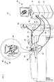
- Fig. 1 is a schematic view of a medical procedure system 20 constructed and operative in accordance with an embodiment of the present invention.
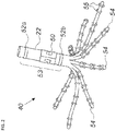
- Fig. 2 is a schematic view of a catheter 40 for use in the system 20 of Fig. 1 .
- the medical procedure system 20 is used to determine the position of the catheter 40, seen in an inset 25 of Fig. 1 and in more detail in Fig. 2 .
- the catheter 40 includes a shaft 22 and a plurality of deflectable arms 54 (only some labeled for the sake of simplicity) for inserting into a body-part of a living subject.
- the deflectable arms 54 have respective proximal ends connected to the distal end of the shaft 22.
- the catheter 40 includes a position sensor 53 disposed on the shaft 22 in a predefined spatial relation to the proximal ends of the deflectable arms 54.
- the position sensor 53 may include a magnetic sensor 50 and/or at least one shaft electrode 52.
- the magnetic sensor 50 may include at least one coil, for example, but not limited to, a dual-axis or a triple axis coil arrangement to provide position data for location and orientation including roll.
- the catheter 40 includes multiple electrodes 55 (only some are labeled in Fig. 2 for the sake of simplicity) disposed at different, respective locations along each of the deflectable arms 54.
- the catheter 40 may be used for mapping electrical activity in a heart of the living subject using the electrodes 55, or for performing any other suitable function in a body-part of a living subject, for example, but not limited to, reversible and/or irreversible electroporation and/or RF ablation.
- the medical procedure system 20 may determine a position and orientation of the shaft 22 of the catheter 40 based on signals provided by the magnetic sensor 50 and/or the shaft electrodes 52 (proximal-electrode 52a and distal-electrode 52b) fitted on the shaft 22, on either side of the magnetic sensor 50.
- the proximal-electrode 52a, the distal-electrode 52b, the magnetic sensor 50 and at least some of the electrodes 55 are connected by wires running through the shaft 22 via a catheter connector 35 to various driver circuitries in a console 24.
- at least two of the electrodes 55 of each of the deflectable arms 54, the shaft electrodes 52, and the magnetic sensor 50 are connected to the driver circuitries in the console 24 via the catheter connector 35.
- the distal-electrode 52b and/or the proximal electrode 52a may be omitted.
- Fig. 2 The illustration shown in Fig. 2 is chosen purely for the sake of conceptual clarity. Other configurations of shaft electrodes 52 and electrodes 55 are possible. Additional functionalities may be included in the position sensor 53. Elements which are not relevant to the disclosed embodiments of the invention, such as irrigation ports, are omitted for the sake of clarity.
- a physician 30 navigates the catheter 40 to a target location in a body part (e.g., a heart 26) of a patient 28 by manipulating the shaft 22 using a manipulator 32 near the proximal end of the catheter 40 and/or deflection from a sheath 23.
- the catheter 40 is inserted through the sheath 23, with the deflectable arms 54 gathered together, and only after the catheter 40 is retracted from the sheath 23, the deflectable arms 54 are able to spread and regain their intended functional shape.
- the sheath 23 also serves to minimize vascular trauma on its way to the target location.
- Console 24 comprises processing circuitry 41, typically a general-purpose computer and a suitable front end and interface circuits 44 for generating signals in, and/or receiving signals from, body surface electrodes 49 which are attached by wires running through a cable 39 to the chest and to the back, or any other suitable skin surface, of the patient 28.
- processing circuitry 41 typically a general-purpose computer and a suitable front end and interface circuits 44 for generating signals in, and/or receiving signals from, body surface electrodes 49 which are attached by wires running through a cable 39 to the chest and to the back, or any other suitable skin surface, of the patient 28.
- Console 24 further comprises a magnetic-sensing sub-system.
- the patient 28 is placed in a magnetic field generated by a pad containing at least one magnetic field radiator 42, which is driven by a unit 43 disposed in the console 24.
- the magnetic field radiator(s) 42 is configured to transmit alternating magnetic fields into a region where the body-part (e.g., the heart 26) is located.
- the magnetic fields generated by the magnetic field radiator(s) 42 generate direction signals in the magnetic sensor 50.
- the magnetic sensor 50 is configured to detect at least part of the transmitted alternating magnetic fields and provide the direction signals as corresponding electrical inputs to the processing circuitry 41.
- the processing circuitry 41 uses the position-signals received from the shaft electrodes 52, the magnetic sensor 50 and the electrodes 55 to estimate a position of the catheter 40 inside an organ, such as inside a cardiac chamber. In some embodiments, the processing circuitry 41 correlates the position signals received from the electrodes 52, 55 with previously acquired magnetic location-calibrated position signals, to estimate the position of the catheter 40 inside a cardiac chamber. The position coordinates of the shaft electrodes 52 and the electrodes 55 may be determined by the processing circuitry 41 based on, among other inputs, measured impedances, or on proportions of currents distribution, between the electrodes 52, 55 and the body surface electrodes 49.
- the console 24 drives a display 27, which shows the distal end of the catheter 40 inside the heart 26.
- the method of position sensing using current distribution measurements and/or external magnetic fields is implemented in various medical applications, for example, in the Carto® system, produced by Biosense Webster Inc. (Irvine, California), and is described in detail in U.S. Patent Nos. 5,391,199 , 6,690,963 , 6,484,118 , 6,239,724 , 6,618,612 , 6,332,089 , 7,756,576 , 7,869,865 , and 7,848,787 , in PCT Patent Publication WO 96/05768 , and in U.S. Patent Application Publication Nos. 2002/0065455 A1 , 2003/0120150 A1 and 2004/0068178 A1 .
- the Carto®3 system applies an Active Current Location (ACL) impedance-based position-tracking method.
- ACL Active Current Location
- the processing circuitry 41 is configured to create a mapping (e.g., current-position matrix (CPM)) between indications of electrical impedance and positions in a magnetic coordinate frame of the magnetic field radiator(s) 42.
- the processing circuitry 41 estimates the positions of the shaft electrodes 52 and the electrodes 55 by performing a lookup in the CPM.
- a mapping e.g., current-position matrix (CPM)
- determining the location of the distal end of the catheter may be used, for example, based on ultrasonic transducers and receivers, using imaging techniques such as ultrasound or MRI or CT scans which may include disposing radiopaque tags on the catheter 40.
- Processing circuitry 41 is typically programmed in software to carry out the functions described herein.
- the software may be downloaded to the computer in electronic form, over a network, for example, or it may, alternatively or additionally, be provided and/or stored on non-transitory tangible media, such as magnetic, optical, or electronic memory.
- Fig. 1 shows only elements related to the disclosed techniques, for the sake of simplicity and clarity.
- the system 20 typically comprises additional modules and elements that are not directly related to the disclosed techniques, and thus are intentionally omitted from Fig. 1 and from the corresponding description.
- the catheter 40 described above includes eight deflectable arms 54 with six electrodes per arm 54. Any suitable catheter may be used instead of the catheter 40, for example, a catheter with a different number of flexible arms and/or electrodes per arm, or a different probe shape such as a balloon catheter or a lasso catheter, by way of example only.
- the medical procedure system 20 may also perform electroporation or RF ablation (or other ablation technique) of heart tissue using any suitable catheter, for example using the catheter 40 or a different catheter and any suitable ablation method.
- the console 24 may include a signal generator 34 configured to generate an electrical signal to be applied by an electrode or electrodes of a catheter connected to the console 24, (and optionally one or more of the body surface electrodes 49), to perform electroporation of RF ablation of a myocardium of the heart 26.
- the console 24 may include a pump (not shown), which pumps irrigation fluid into an irrigation channel to a distal end of a catheter performing RF ablation.
- the catheter performing the RF ablation may also include temperature sensors (not shown) which are used to measure a temperature of the myocardium during RF ablation and regulate an ablation power and/or an irrigation rate of the pumping of the irrigation fluid according to the measured temperature.
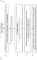
- Fig. 3 is a flowchart 60 including steps in a method of operation of the medical procedure system 20 of Fig. 1 .
- the catheter 40 ( Fig. 1 ) is configured to be inserted (block 62) into a chamber of the heart 26 ( Fig. 1 ).
- the signal generator 34 ( Fig. 1 ) is coupled to at least two of the electrodes 55 ( Fig. 2 ) of the catheter 40.
- the signal generator 34 is configured to generate (block 64) an electrical signal for supply to at least two of the electrodes 55 which responsively to the electrical signal apply an electrical field to tissue of the chamber of the heart 26 at a given location within the chamber.
- the electrical field has an amplitude sufficient to cause reversible electroporation, but below a threshold for irreversible electroporation.
- the field may be applied between any two of the electrodes 55, for example, between adjacent electrodes 55, and/or between some of the electrodes 55 and a reference electrode of the electrodes 55.
- the electrical field applied by the electrodes 55 to the tissue at the given location is generally less than 450 Volts per centimeter.
- the electrical signal supplied by the signal generator 34 may be a pulsed electrical signal.
- the pulsed electrical signal may include a series of biphasic pulses, with each biphasic pulse including a positive and a negative phase pulse.
- the series of biphasic pulses may include a positive phase pulse of 2 microseconds, followed by a delay of 0.5 microseconds, followed by a negative phase pulse of 2 microseconds, and so on.
- the pulsed electrical signal may include a series of bursts, with each burst including a series of pulses, such as the biphasic pulses or a single-phase pulse.
- Each of the pulses may have any suitable length, for example, between 1 and 20 microseconds.
- the series of bursts includes a gap between bursts of any suitable length, for example, between 100 microseconds to 1000 milliseconds.
- Each burst may include any suitable number of pulses, for example, up to 100 pulses.
- the series of bursts may include any suitable number of bursts, for example, up to 100 bursts.
- the various parameters of the electrical signals may be suitably adjusted to provide an electrical field which causes reversible electroporation into the tissue to a depth of at least 2-3 mm without substantially heating surrounding tissue.
- the term "without substantially heating surrounding tissue” as used in the specification and claims, is defined as heating the tissue to a level at which there is no clinical effect. In some applications a three degrees centigrade increase in temperature may be acceptable for the durations used in electroporation.
- the effect of the reversible electroporation on the electrical activation signals in the tissue of the chamber of the heart 26 in the vicinity of the location where the electric field was/is being applied is measured.
- the processing circuitry 41 is configured to receive (block 66) from the catheter 40 electrical activation signals in the tissue of the chamber of the heart 26 in the vicinity of the location.
- the processing circuitry 41 is configured to measure (block 68) an effect of the reversible electroporation on the electrical activation signals in the tissue of the chamber of the heart 26 in the vicinity of the location.
- Measuring an effect of the reversible electroporation may include measuring an amplitude of signals captured from the vicinity of the location, and/or processing the signals to generate graphs of the signals and/or generating an electroanatomic map based on the electrical activation signals.
- the "vicinity" of the location may be in and/or around the location at which the reversible electroporation is performed.
- the processing circuitry 41 is configured to generate (block 70) an electroanatomic map of the chamber of the heart responsively to the electrical activation signals.
- the step of block 70 is described in more detail with reference to Fig. 5 below.
- the processing circuitry 41 is configured to render (block 72) to the display 27 an indication of the electrical activation signals in the tissue of the chamber of the heart in the vicinity of the location.
- the indication may include an amplitude or amplitudes of the activation signals, a graph or graphs of the activation signals or an electroanatomic map representing the activation signals.
- a substance before, during or after inducing the reversible electroporation in the tissue, a substance may be applied to the tissue, and the effect of the reversible electroporation and the substance on the electrical activation signals may be examined.
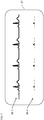
- FIG. 4 is a schematic view of intracardiac electrograms 80 generated by the system 20 of Fig. 1 .
- the intracardiac electrograms 80-1, 80-2 are rendered to the display 27 by the processing circuitry 41 ( Fig. 1 ) and represent electrical activation signals captured at a point around the location of the reversible electroporation, prior to the reversible electroporation being applied (shown in intracardiac electrogram 80-1) and during or substantially immediately after the reversible electroporation has been applied (shown in intracardiac electrograms 80-2), respectively. It can be seen that the reversible electroporation has had an effect on reducing electrical activity at the point around the location.
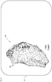
- Fig. 5 is a schematic view of an electroanatomic map 82 generated by the system 20 of Fig. 1 . Reference is also made to Fig. 3 .
- the processing circuitry 41 ( Fig. 1 ) is configured to process the electrical activation signals captured by the catheter 40 ( Fig. 1 ) over time at multiple sample locations over the surface of the chamber(s) of the heart 26 to determine respective activation times at the multiple locations over the surface of the chamber(s) of the heart 26.
- the processing circuitry 41 is configured to prepare the electroanatomic map 82 including a plurality of velocity vectors 84 (only some labeled for the sake of simplicity) describing the propagation of activation wavefronts associated with the activation times.
- One method for preparing the electroanatomic map 82 is described in US Patent No. 6,301,496 . Any suitable method for preparing the electroanatomic map 82 may also be used.
- Other electroanatomic maps may be generated for example, showing activation times using colors.
- the processing circuitry 41 is configured to render (block 74) the electroanatomic map 82 to the display 27.
- the electroanatomic map 82 may be displayed alongside another electroanatomic map representing electrical activity of the chamber(s) of the heart 26 prior to the reversible electroporation being performed in order to further visualize the effect of the reversible electroporation.
- the physician examines the intracardiac electrograms 80 ( Fig. 4 ) and/or the electroanatomic map 82 ( Fig. 5 ) or other data to determine if the location at which reversible electroporation was applied should be permanently ablated using IRE or another ablation technique or not ablated at all. If the physician decides to permanently ablate, the physician operates the system 20 to perform the ablation.
- the signal generator 34 ( Fig. 1 ) is configured to generate another electrical signal for supply to at least two of the electrodes 55 which responsively to the other electrical signal apply another electrical field to tissue of the chamber of the heart 26 ( Fig. 1 ) at the location within the chamber with an amplitude sufficient to cause irreversible electroporation (block 76).
- the physician could use another form of ablation, such as RF ablation which kills the cells of the tissue due to its heating effect.
- the field may be applied between any two of the electrodes 55, for example, between adjacent electrodes 55, and/or between some of the electrodes 55 and a reference electrode of the electrodes 55.
- the electrical field applied by the electrodes 55 to the tissue at the given location is generally more than 800 Volts per centimeter.
- the electrical signal supplied by the signal generator 34 may be a pulsed electrical signal.
- the pulsed electrical signal may include a series of biphasic pulses, with each biphasic pulse including a positive and a negative phase pulse.
- the series of biphasic pulses may include a positive phase pulse of 2 microseconds, followed by a delay of 0.5 microseconds, followed by a negative phase pulse of 2 microseconds, and so on.
- the pulsed electrical signal may include a series of bursts, with each burst including a series of pulses, such as the biphasic pulses or a single-phase pulse.
- Each of the pulses may have any suitable length, for example, between 1 and 20 microseconds.
- the series of bursts includes a gap between bursts of any suitable length, for example, between 100 microseconds to 1000 milliseconds.
- Each burst may include any suitable number of pulses, for example, up to 100 pulses.
- the series of bursts may include any suitable number of bursts, for example, up to 100 bursts.
- the various parameters of the electrical signals may be suitably adjusted to provide an electrical field which causes IRE and a lesion in the tissue to a depth of at least 2-3 mm without substantially heating surrounding tissue.
- the terms “about” or “approximately” for any numerical values or ranges indicate a suitable dimensional tolerance that allows the part or collection of components to function for its intended purpose as described herein. More specifically, “about” or “approximately” may refer to the range of values ⁇ 20% of the recited value, e.g. "about 90%” may refer to the range of values from 71% to 99%.
Landscapes
- Health & Medical Sciences (AREA)
- Life Sciences & Earth Sciences (AREA)
- Engineering & Computer Science (AREA)
- Surgery (AREA)
- Public Health (AREA)
- Animal Behavior & Ethology (AREA)
- Veterinary Medicine (AREA)
- General Health & Medical Sciences (AREA)
- Biomedical Technology (AREA)
- Heart & Thoracic Surgery (AREA)
- Medical Informatics (AREA)
- Molecular Biology (AREA)
- Physics & Mathematics (AREA)
- Biophysics (AREA)
- Nuclear Medicine, Radiotherapy & Molecular Imaging (AREA)
- Pathology (AREA)
- Cardiology (AREA)
- Plasma & Fusion (AREA)
- Otolaryngology (AREA)
- Radiology & Medical Imaging (AREA)
- Physiology (AREA)
- Human Computer Interaction (AREA)
- Gynecology & Obstetrics (AREA)
- Oral & Maxillofacial Surgery (AREA)
- Vascular Medicine (AREA)
- Surgical Instruments (AREA)
- Measurement And Recording Of Electrical Phenomena And Electrical Characteristics Of The Living Body (AREA)
- Electrotherapy Devices (AREA)
Abstract
Description
- The present application claims benefit of
US Provisional Patent Application Serial Number 62/942,999 to Altmann, et al., filed 3 December 2019 - The present invention relates to medical systems, and in particular, but not exclusively, to reversible electroporation.
- A wide range of medical procedures involve placing probes, such as catheters, within a patient's body. Location sensing systems have been developed for tracking such probes. Magnetic location sensing is one of the methods known in the art. In magnetic location sensing, magnetic field generators are typically placed at known locations external to the patient. A magnetic field sensor within the distal end of the probe generates electrical signals in response to these magnetic fields, which are processed to determine the coordinate locations of the distal end of the probe. These methods and systems are described in
U.S. Pat. Nos. 5,391,199 ,6,690,963 ,6,484,118 ,6,239,724 ,6,618,612 and6,332,089 , inPCT International Publication No. WO 1996/005768 , and inU.S. Patent Application Publications Nos. 2002/006455 and2003/0120150 and2004/0068178 . Locations may also be tracked using impedance or current based systems. - One medical procedure in which these types of probes or catheters have proved extremely useful is in the treatment of cardiac arrhythmias. Cardiac arrhythmias and atrial fibrillation in particular, persist as common and dangerous medical ailments, especially in the aging population.
- Diagnosis and treatment of cardiac arrhythmias include mapping the electrical properties of heart tissue, especially the endocardium and the heart volume, and selectively ablating cardiac tissue by application of energy. Such ablation can cease or modify the propagation of unwanted electrical signals from one portion of the heart to another. The ablation process destroys the unwanted electrical pathways by formation of non-conducting lesions. Various energy delivery modalities have been disclosed for forming lesions, and include use of microwave, laser and more commonly, radiofrequency energies to create conduction blocks along the cardiac tissue wall. In a two-step procedure, mapping followed by ablation, electrical activity at points within the heart is typically sensed and measured by advancing a catheter containing one or more electrical sensors into the heart, and acquiring data at a multiplicity of points. These data are then utilized to select the endocardial target areas at which the ablation is to be performed.
- Electrode catheters have been in common use in medical practice for many years. They are used to stimulate and map electrical activity in the heart and to ablate sites of aberrant electrical activity. In use, the electrode catheter is inserted into a major vein or artery, e.g., femoral artery, and then guided into the chamber of the heart of concern. A typical ablation procedure involves the insertion of a catheter having a one or more electrodes at its distal end into a heart chamber. A reference electrode may be provided, generally taped to the skin of the patient or by means of a second catheter that is positioned in or near the heart. RF (radio frequency) current is applied to the tip electrode(s) of the ablating catheter, and current flows through the media that surrounds it, i.e., blood and tissue, toward the reference electrode. The distribution of current depends on the amount of electrode surface in contact with the tissue as compared to blood, which has a higher conductivity than the tissue. Heating of the tissue occurs due to its electrical resistance. The tissue is heated sufficiently to cause cellular destruction in the cardiac tissue resulting in formation of a lesion within the cardiac tissue which is electrically non-conductive.
-
US Patent Publication No. 2017/0348525 to Sano, et al. , describes a ratio of reversible electroporation and irreversible electroporation controlled by selecting a symmetric waveform or asymmetric waveform to either minimize or enhance irreversible effects on cells in the target tissue. Combined reversible and irreversible electroporation includes inserting one or more therapeutic electrodes into a target tissue, introducing an electroporation compound into the target tissue, selecting a pulse waveform that is either 1) asymmetric bipolar that has positive and negative pulses with different durations, or 2) symmetric bipolar that has positive and negative pulses with the same duration, and delivering to the target tissue a series of electrical pulses having the selected pulse waveform. -
US Patent No. 10,245,098 to Davalos, et al. -
US Patent No. 10,154,874 to Davalos, et al. -
US Patent No. 10,010,666 to Rubinsky, et al. -
US Patent No. 9,345,538 to Deem, et al. -
US Patent No. 7,937,143 to Demarais, et al. , describes methods and apparatus for inducing, monitoring and controlling renal neuromodulation using a pulsed electric field to effectuate electroporation or electrofusion. In some embodiments, tissue impedance, conductance or conductivity may be monitored to determine the effects of pulsed electric field therapy, e.g., to determine an extent of electroporation and its degree of irreversibility. Pulsed electric field electroporation of tissue causes a decrease in tissue impedance and an increase in tissue conductivity. If induced electroporation is reversible, upon cessation of the pulsed electric field, tissue impedance and conductivity should approximate baseline levels; however, if electroporation is irreversible, impedance and conductivity changes should persist. Thus, monitoring of impedance or conductivity may be utilized to determine the onset of electroporation and to determine the type or extent of electroporation. Furthermore, monitoring data may be used in one or more manual or automatic feedback loops to control the electroporation. - There is provided in accordance with an embodiment of the present invention, a electroporation method, including inserting a catheter having multiple electrodes into a chamber of a heart, applying an electrical field using at least two of the electrodes to tissue of the chamber of the heart at a given location within the chamber with an amplitude sufficient to cause reversible electroporation, but below a threshold for irreversible electroporation, and measuring an effect of the reversible electroporation on electrical activation signals in the tissue of the chamber of the heart in a vicinity of the location.
- Further in accordance with an embodiment of the present invention the electrical field is less than 450 Volts per centimeter.
- Still further in accordance with an embodiment of the present invention, the method includes generating a pulsed electrical signal and wherein the applying the electrical field includes applying the electrical field using the at least two electrodes responsively to the generated pulsed electrical signal.
- Additionally, in accordance with an embodiment of the present invention the pulsed electrical signal includes a series of biphasic pulses, each biphasic pulse including a positive and a negative phase pulse.
- Moreover, in accordance with an embodiment of the present invention the pulsed electrical signal includes a series of bursts, each burst including a series of pulses.
- Further in accordance with an embodiment of the present inention each of the pulses has a pulse length between 1 and 20 microseconds, and the series of bursts includes a gap between bursts of between 100 microseconds to 1000 milliseconds.
- Still further in accordance with an embodiment of the present invention each burst includes up to 100 of the pulses, and the series of bursts includes up to 100 bursts.
- Additionally in accordance with an embodiment of the present invention, the method includes rendering to a display an indication of the electrical activation signals in the tissue of the chamber of the heart in the vicinity of the location, and then applying another electrical field using at least two of the electrodes to the tissue of the chamber of the heart at the given location within the chamber with an amplitude sufficient to cause irreversible electroporation.
- Moreover, in accordance with an embodiment of the present invention, the method includes generating an electroanatomic map of the chamber of the heart responsively to the electrical activation signals, and rendering the electroanatomic map to the display.
- Further in accordance with an embodiment of the present invention the electric field with the amplitude sufficient to cause reversible electroporation but below a threshold for irreversible electroporation is less than 450 Volts per centimeter, and the other electric field with the amplitude sufficient to cause irreversible electroporation is greater than 800 Volts per centimeter.
- Still further in accordance with an embodiment of the present invention, the method includes generating a pulsed electrical signal and wherein the applying the other electrical field includes applying the other electrical field using the at least two electrodes responsively to the generated pulsed electrical signal.
- Additionally, in accordance with an embodiment of the present invention the pulsed electrical signal includes a series of biphasic pulses, each biphasic pulse including a positive and a negative phase pulse.
- Moreover, in accordance with an embodiment of the present invention the pulsed electrical signal includes a series of bursts, each burst including a series of pulses.
- Further in accordance with an embodiment of the present invention each of the pulses has a pulse length between 1 and 20 microseconds, and the series of bursts includes a gap between bursts of between 100 microseconds to 1000 milliseconds.
- Still further in accordance with an embodiment of the present invention each burst includes up to 100 of the pulses, and the series of bursts includes up to 100 bursts.
- There is also provided in accordance with another embodiment of the present invention a electroporation system, including a catheter including multiple electrodes, and configured to be inserted into a chamber of a heart, a signal generator coupled to at least two of the electrodes, and configured to generate an electrical signal for supply to the at least two electrodes which responsively to the electrical signal apply an electrical field to tissue of the chamber of the heart at a given location within the chamber, the electrical field having an amplitude sufficient to cause reversible electroporation, but below a threshold for irreversible electroporation, and processing circuitry configured to receive from the catheter electrical activation signals in the tissue of the chamber of the heart in a vicinity of the location, and measure an effect of the reversible electroporation on the electrical activation signals in the tissue of the chamber of the heart in a vicinity of the location.
- Additionally, in accordance with an embodiment of the present invention the electrical field is less than 450 Volts per centimeter.
- Moreover, in accordance with an embodiment of the present invention the electrical signal is a pulsed electrical signal.
- Further in accordance with an embodiment of the present invention the pulsed electrical signal includes a series of biphasic pulses, each biphasic pulse including a positive and a negative phase pulse.
- Still further in accordance with an embodiment of the present invention the pulsed electrical signal includes a series of bursts, each burst including a series of pulses.
- Additionally, in accordance with an embodiment of the present invention each of the pulses has a pulse length between 1 and 20 microseconds, and the series of bursts includes a gap between bursts of between 100 microseconds to 1000 milliseconds.
- Moreover, in accordance with an embodiment of the present invention each burst includes up to 100 of the pulses, and the series of bursts includes up to 100 bursts.
- Further in accordance with an embodiment of the present invention the processing circuitry is configured to render to a display an indication of the electrical activation signals in the tissue of the chamber of the heart in the vicinity of the location, and the signal generator is configured to generate another electrical signal for supply to at least two of the electrodes which responsively to the other electrical signal apply another electrical field to tissue of the chamber of the heart at the location within the chamber with an amplitude sufficient to cause irreversible electroporation.
- Still further in accordance with an embodiment of the present invention the processing circuitry is configured to generate an electroanatomic map of the chamber of the heart responsively to the electrical activation signals, and render the electroanatomic map to the display.
- Additionally, in accordance with an embodiment of the present invention the electric field with the amplitude sufficient to cause reversible electroporation but below a threshold for irreversible electroporation is less than 450 Volts per centimeter, and the other electric field with the amplitude sufficient to cause irreversible electroporation is greater than 800 Volts per centimeter.
- Moreover, in accordance with an embodiment of the present invention the other electrical signal is a pulsed electrical signal.
- Further in accordance with an embodiment of the present invntion the pulsed electrical signal includes a series of biphasic pulses, each biphasic pulse including a positive and a negative phase pulse.
- Still further in accordance with an embodiment of the present invention the pulsed electrical signal includes a series of bursts, each burst including a series of pulses.
- Additionally, in accordance with an embodiment of the present invention each of the pulses has a pulse length between 1 and 20 microseconds, and the series of bursts includes a gap between bursts of between 100 microseconds to 1000 milliseconds.
- Moreover, in accordance with an embodiment of the present invention each burst includes up to 100 of the pulses, and the series of bursts includes up to 100 bursts.
- The present invention will be understood from the following detailed description, taken in conjunction with the drawings in which:
-
Fig. 1 is a schematic view of a medical procedure system constructed and operative in accordance with an exemplary embodiment of the present invention; -
Fig. 2 is a schematic view of a catheter for use in the system ofFig. 1 ; -
Fig. 3 is a flowchart including steps in a method of operation of the medical procedure system ofFig. 1 ; -
Fig. 4 is a schematic view of intracardiac electrograms generated by the system ofFig. 1 ; and -
Fig. 5 is a schematic view of an electroanatomic map generated by the system ofFig. 1 . - Irreversible electroporation (IRE) applies short electrical pulses that generate high enough electrical fields (typically greater than 450 Volts per centimeter) to irreversibly damage the cells. Non-thermal IRE may be used in treating different types of tumors and other unwanted tissue without causing thermal damage to surrounding tissue. Small electrodes are placed in proximity to target tissue to apply short electrical pulses. The pulses increase the resting transmembrane potential, so that nanopores form in the plasma membrane. When the electricity applied to the tissue is above the electric field threshold of the target tissue, the cells become permanently permeable from the formation of nanopores. As a result, the cells are unable to repair the damage and die due to a loss of homeostasis and the cells typically die by apoptosis.
- IRE may be used for cardiac ablation as an alternative to other cardiac ablation techniques, e.g., radio-frequency (RF) cardiac ablation. IRE cardiac ablation is sometimes referred to as Pulse Field Ablation (PFA). As IRE is generally a low thermal technique, IRE may reduce the risk of collateral cell damage that is present with the other techniques. e.g., in RF cardiac ablation. However, similar to other ablation techniques, such as RF cardiac ablation, until after IRE pulses have actually been applied to a target location of the heart, thereby killing the cells in the target location, a physician may not be certain that killing the cells of the target location is the correct procedure to be followed.
- Exemplary embodiments of the invention solve the above problems by applying an electrical field to induce reversible electroporation at a target location. Reversible electroporation applies short electrical pulses, generating high electrical fields (up to around 450 Volts per centimeter), to cells so as to temporarily break down the membranes of cells. Reversible electroporation occurs when the electricity applied with the electrodes is below the electric field threshold of the target tissue allowing cells to repair. Reversible electroporation does not kill the cells, but allows a physician to see the effect of reversible electroporation on electrical activation signals in the vicinity of the target location.
- While the reversible electroporation is being induced, or substantially immediately afterwards, for example, up to about a few seconds afterwards. electrical activation signals from the vicinity of the target location are acquired. The acquired signals may be processed to provide a visual indication or indications of the electrical activation signals. The visual indication(s) may be compared with those prior to the application of the reversible electroporation, to check if an expected change in the electrical activity of the target location has actually occurred. Additionally, or alternatively, the electrical activation signals may be processed to generate an electroanatomic map which may then be compared with an electroanatomic map generated prior to the application of the reversible electroporation.
- After the effect of the reversible electroporation on electrical activation signals in the vicinity of the target location has been evaluated by the physician, the physician may decide whether or not to perform another procedure, such as, IRE or RF cardiac ablation at the target location. For example, if an expected change has in fact occurred, IRE (or another suitable ablation technique) may be applied to the target location to irreversibly kill the cells of the target location. If no expected change is observed, IRE (or another suitable ablation technique) may not be applied to the location.
- Applying reversible electroporation to a target location prior to applying IRE (or another suitable ablation technique) to the location allows the physician to check if ablating the location gives an expected result. The reversibility of reversible electroporation enables the physician to perform the check without there being any permanent damage to the heart tissue.
- Reference is now made to
Fig. 1 , which is a schematic view of amedical procedure system 20 constructed and operative in accordance with an embodiment of the present invention. Reference is also made toFig. 2 , which is a schematic view of acatheter 40 for use in thesystem 20 ofFig. 1 . - The
medical procedure system 20 is used to determine the position of thecatheter 40, seen in aninset 25 ofFig. 1 and in more detail inFig. 2 . Thecatheter 40 includes ashaft 22 and a plurality of deflectable arms 54 (only some labeled for the sake of simplicity) for inserting into a body-part of a living subject. Thedeflectable arms 54 have respective proximal ends connected to the distal end of theshaft 22. - The
catheter 40 includes aposition sensor 53 disposed on theshaft 22 in a predefined spatial relation to the proximal ends of thedeflectable arms 54. Theposition sensor 53 may include amagnetic sensor 50 and/or at least one shaft electrode 52. Themagnetic sensor 50 may include at least one coil, for example, but not limited to, a dual-axis or a triple axis coil arrangement to provide position data for location and orientation including roll. Thecatheter 40 includes multiple electrodes 55 (only some are labeled inFig. 2 for the sake of simplicity) disposed at different, respective locations along each of thedeflectable arms 54. Typically, thecatheter 40 may be used for mapping electrical activity in a heart of the living subject using theelectrodes 55, or for performing any other suitable function in a body-part of a living subject, for example, but not limited to, reversible and/or irreversible electroporation and/or RF ablation. - The
medical procedure system 20 may determine a position and orientation of theshaft 22 of thecatheter 40 based on signals provided by themagnetic sensor 50 and/or the shaft electrodes 52 (proximal-electrode 52a and distal-electrode 52b) fitted on theshaft 22, on either side of themagnetic sensor 50. The proximal-electrode 52a, the distal-electrode 52b, themagnetic sensor 50 and at least some of theelectrodes 55 are connected by wires running through theshaft 22 via acatheter connector 35 to various driver circuitries in aconsole 24. In some embodiments, at least two of theelectrodes 55 of each of thedeflectable arms 54, the shaft electrodes 52, and themagnetic sensor 50 are connected to the driver circuitries in theconsole 24 via thecatheter connector 35. In some embodiments, the distal-electrode 52b and/or theproximal electrode 52a may be omitted. - The illustration shown in
Fig. 2 is chosen purely for the sake of conceptual clarity. Other configurations of shaft electrodes 52 andelectrodes 55 are possible. Additional functionalities may be included in theposition sensor 53. Elements which are not relevant to the disclosed embodiments of the invention, such as irrigation ports, are omitted for the sake of clarity. - A
physician 30 navigates thecatheter 40 to a target location in a body part (e.g., a heart 26) of a patient 28 by manipulating theshaft 22 using amanipulator 32 near the proximal end of thecatheter 40 and/or deflection from asheath 23. Thecatheter 40 is inserted through thesheath 23, with thedeflectable arms 54 gathered together, and only after thecatheter 40 is retracted from thesheath 23, thedeflectable arms 54 are able to spread and regain their intended functional shape. By containingdeflectable arms 54 together, thesheath 23 also serves to minimize vascular trauma on its way to the target location. -
Console 24 comprises processingcircuitry 41, typically a general-purpose computer and a suitable front end andinterface circuits 44 for generating signals in, and/or receiving signals from,body surface electrodes 49 which are attached by wires running through acable 39 to the chest and to the back, or any other suitable skin surface, of thepatient 28. -
Console 24 further comprises a magnetic-sensing sub-system. Thepatient 28 is placed in a magnetic field generated by a pad containing at least onemagnetic field radiator 42, which is driven by aunit 43 disposed in theconsole 24. The magnetic field radiator(s) 42 is configured to transmit alternating magnetic fields into a region where the body-part (e.g., the heart 26) is located. The magnetic fields generated by the magnetic field radiator(s) 42 generate direction signals in themagnetic sensor 50. Themagnetic sensor 50 is configured to detect at least part of the transmitted alternating magnetic fields and provide the direction signals as corresponding electrical inputs to theprocessing circuitry 41. - In some embodiments, the
processing circuitry 41 uses the position-signals received from the shaft electrodes 52, themagnetic sensor 50 and theelectrodes 55 to estimate a position of thecatheter 40 inside an organ, such as inside a cardiac chamber. In some embodiments, theprocessing circuitry 41 correlates the position signals received from theelectrodes 52, 55 with previously acquired magnetic location-calibrated position signals, to estimate the position of thecatheter 40 inside a cardiac chamber. The position coordinates of the shaft electrodes 52 and theelectrodes 55 may be determined by theprocessing circuitry 41 based on, among other inputs, measured impedances, or on proportions of currents distribution, between theelectrodes 52, 55 and thebody surface electrodes 49. Theconsole 24 drives adisplay 27, which shows the distal end of thecatheter 40 inside theheart 26. - The method of position sensing using current distribution measurements and/or external magnetic fields is implemented in various medical applications, for example, in the Carto® system, produced by Biosense Webster Inc. (Irvine, California), and is described in detail in
U.S. Patent Nos. 5,391,199 ,6,690,963 ,6,484,118 ,6,239,724 ,6,618,612 ,6,332,089 ,7,756,576 ,7,869,865 , and7,848,787 , inPCT Patent Publication WO 96/05768 U.S. Patent Application Publication Nos. 2002/0065455 A1 ,2003/0120150 A1 and2004/0068178 A1 . - The Carto®3 system applies an Active Current Location (ACL) impedance-based position-tracking method. In some embodiments, using the ACL method, the
processing circuitry 41 is configured to create a mapping (e.g., current-position matrix (CPM)) between indications of electrical impedance and positions in a magnetic coordinate frame of the magnetic field radiator(s) 42. Theprocessing circuitry 41 estimates the positions of the shaft electrodes 52 and theelectrodes 55 by performing a lookup in the CPM. - Other methods of determining the location of the distal end of the catheter may be used, for example, based on ultrasonic transducers and receivers, using imaging techniques such as ultrasound or MRI or CT scans which may include disposing radiopaque tags on the
catheter 40. -
Processing circuitry 41 is typically programmed in software to carry out the functions described herein. The software may be downloaded to the computer in electronic form, over a network, for example, or it may, alternatively or additionally, be provided and/or stored on non-transitory tangible media, such as magnetic, optical, or electronic memory. -
Fig. 1 shows only elements related to the disclosed techniques, for the sake of simplicity and clarity. Thesystem 20 typically comprises additional modules and elements that are not directly related to the disclosed techniques, and thus are intentionally omitted fromFig. 1 and from the corresponding description. - The
catheter 40 described above includes eightdeflectable arms 54 with six electrodes perarm 54. Any suitable catheter may be used instead of thecatheter 40, for example, a catheter with a different number of flexible arms and/or electrodes per arm, or a different probe shape such as a balloon catheter or a lasso catheter, by way of example only. - The
medical procedure system 20 may also perform electroporation or RF ablation (or other ablation technique) of heart tissue using any suitable catheter, for example using thecatheter 40 or a different catheter and any suitable ablation method. Theconsole 24 may include asignal generator 34 configured to generate an electrical signal to be applied by an electrode or electrodes of a catheter connected to theconsole 24, (and optionally one or more of the body surface electrodes 49), to perform electroporation of RF ablation of a myocardium of theheart 26. Theconsole 24 may include a pump (not shown), which pumps irrigation fluid into an irrigation channel to a distal end of a catheter performing RF ablation. The catheter performing the RF ablation may also include temperature sensors (not shown) which are used to measure a temperature of the myocardium during RF ablation and regulate an ablation power and/or an irrigation rate of the pumping of the irrigation fluid according to the measured temperature. - Reference is now made to
Fig. 3 , which is aflowchart 60 including steps in a method of operation of themedical procedure system 20 ofFig. 1 . - The catheter 40 (
Fig. 1 ) is configured to be inserted (block 62) into a chamber of the heart 26 (Fig. 1 ). - The signal generator 34 (
Fig. 1 ) is coupled to at least two of the electrodes 55 (Fig. 2 ) of thecatheter 40. Thesignal generator 34 is configured to generate (block 64) an electrical signal for supply to at least two of theelectrodes 55 which responsively to the electrical signal apply an electrical field to tissue of the chamber of theheart 26 at a given location within the chamber. The electrical field has an amplitude sufficient to cause reversible electroporation, but below a threshold for irreversible electroporation. The field may be applied between any two of theelectrodes 55, for example, betweenadjacent electrodes 55, and/or between some of theelectrodes 55 and a reference electrode of theelectrodes 55. The electrical field applied by theelectrodes 55 to the tissue at the given location is generally less than 450 Volts per centimeter. The electrical signal supplied by thesignal generator 34 may be a pulsed electrical signal. The pulsed electrical signal may include a series of biphasic pulses, with each biphasic pulse including a positive and a negative phase pulse. For example, the series of biphasic pulses may include a positive phase pulse of 2 microseconds, followed by a delay of 0.5 microseconds, followed by a negative phase pulse of 2 microseconds, and so on. The pulsed electrical signal may include a series of bursts, with each burst including a series of pulses, such as the biphasic pulses or a single-phase pulse. Each of the pulses may have any suitable length, for example, between 1 and 20 microseconds. The series of bursts includes a gap between bursts of any suitable length, for example, between 100 microseconds to 1000 milliseconds. Each burst may include any suitable number of pulses, for example, up to 100 pulses. The series of bursts may include any suitable number of bursts, for example, up to 100 bursts. - The various parameters of the electrical signals (such as amplitude, pulse length, gap, and number of pulses and bursts) may be suitably adjusted to provide an electrical field which causes reversible electroporation into the tissue to a depth of at least 2-3 mm without substantially heating surrounding tissue. The term "without substantially heating surrounding tissue" as used in the specification and claims, is defined as heating the tissue to a level at which there is no clinical effect. In some applications a three degrees centigrade increase in temperature may be acceptable for the durations used in electroporation.
- During the time period in which the electric field is being applied, or substantially immediately afterwards, the effect of the reversible electroporation on the electrical activation signals in the tissue of the chamber of the
heart 26 in the vicinity of the location where the electric field was/is being applied is measured. - The
processing circuitry 41 is configured to receive (block 66) from thecatheter 40 electrical activation signals in the tissue of the chamber of theheart 26 in the vicinity of the location. - The
processing circuitry 41 is configured to measure (block 68) an effect of the reversible electroporation on the electrical activation signals in the tissue of the chamber of theheart 26 in the vicinity of the location. Measuring an effect of the reversible electroporation may include measuring an amplitude of signals captured from the vicinity of the location, and/or processing the signals to generate graphs of the signals and/or generating an electroanatomic map based on the electrical activation signals. The "vicinity" of the location may be in and/or around the location at which the reversible electroporation is performed. - Therefore, in some embodiments, the
processing circuitry 41 is configured to generate (block 70) an electroanatomic map of the chamber of the heart responsively to the electrical activation signals. The step ofblock 70 is described in more detail with reference toFig. 5 below. - The
processing circuitry 41 is configured to render (block 72) to thedisplay 27 an indication of the electrical activation signals in the tissue of the chamber of the heart in the vicinity of the location. The indication may include an amplitude or amplitudes of the activation signals, a graph or graphs of the activation signals or an electroanatomic map representing the activation signals. - In some embodiments, before, during or after inducing the reversible electroporation in the tissue, a substance may be applied to the tissue, and the effect of the reversible electroporation and the substance on the electrical activation signals may be examined.
- Reference is now made to
Fig. 4 , which is a schematic view of intracardiac electrograms 80 generated by thesystem 20 ofFig. 1 . The intracardiac electrograms 80-1, 80-2 are rendered to thedisplay 27 by the processing circuitry 41 (Fig. 1 ) and represent electrical activation signals captured at a point around the location of the reversible electroporation, prior to the reversible electroporation being applied (shown in intracardiac electrogram 80-1) and during or substantially immediately after the reversible electroporation has been applied (shown in intracardiac electrograms 80-2), respectively. It can be seen that the reversible electroporation has had an effect on reducing electrical activity at the point around the location. - Reference is now made to
Fig. 5 , which is a schematic view of anelectroanatomic map 82 generated by thesystem 20 ofFig. 1 . Reference is also made toFig. 3 . - The processing circuitry 41 (
Fig. 1 ) is configured to process the electrical activation signals captured by the catheter 40 (Fig. 1 ) over time at multiple sample locations over the surface of the chamber(s) of theheart 26 to determine respective activation times at the multiple locations over the surface of the chamber(s) of theheart 26. Theprocessing circuitry 41 is configured to prepare theelectroanatomic map 82 including a plurality of velocity vectors 84 (only some labeled for the sake of simplicity) describing the propagation of activation wavefronts associated with the activation times. One method for preparing theelectroanatomic map 82 is described inUS Patent No. 6,301,496 . Any suitable method for preparing theelectroanatomic map 82 may also be used. Other electroanatomic maps may be generated for example, showing activation times using colors. - The
processing circuitry 41 is configured to render (block 74) theelectroanatomic map 82 to thedisplay 27. Theelectroanatomic map 82 may be displayed alongside another electroanatomic map representing electrical activity of the chamber(s) of theheart 26 prior to the reversible electroporation being performed in order to further visualize the effect of the reversible electroporation. - Reference is again made to
Fig. 3 . The physician examines the intracardiac electrograms 80 (Fig. 4 ) and/or the electroanatomic map 82 (Fig. 5 ) or other data to determine if the location at which reversible electroporation was applied should be permanently ablated using IRE or another ablation technique or not ablated at all. If the physician decides to permanently ablate, the physician operates thesystem 20 to perform the ablation. The signal generator 34 (Fig. 1 ) is configured to generate another electrical signal for supply to at least two of theelectrodes 55 which responsively to the other electrical signal apply another electrical field to tissue of the chamber of the heart 26 (Fig. 1 ) at the location within the chamber with an amplitude sufficient to cause irreversible electroporation (block 76). Alternatively, the physician could use another form of ablation, such as RF ablation which kills the cells of the tissue due to its heating effect. - The field may be applied between any two of the
electrodes 55, for example, betweenadjacent electrodes 55, and/or between some of theelectrodes 55 and a reference electrode of the electrodes 55.The electrical field applied by theelectrodes 55 to the tissue at the given location is generally more than 800 Volts per centimeter. The electrical signal supplied by thesignal generator 34 may be a pulsed electrical signal. The pulsed electrical signal may include a series of biphasic pulses, with each biphasic pulse including a positive and a negative phase pulse. For example, the series of biphasic pulses may include a positive phase pulse of 2 microseconds, followed by a delay of 0.5 microseconds, followed by a negative phase pulse of 2 microseconds, and so on. The pulsed electrical signal may include a series of bursts, with each burst including a series of pulses, such as the biphasic pulses or a single-phase pulse. Each of the pulses may have any suitable length, for example, between 1 and 20 microseconds. The series of bursts includes a gap between bursts of any suitable length, for example, between 100 microseconds to 1000 milliseconds. Each burst may include any suitable number of pulses, for example, up to 100 pulses. The series of bursts may include any suitable number of bursts, for example, up to 100 bursts. The various parameters of the electrical signals (such as amplitude, pulse length, gap, and number of pulses and bursts) may be suitably adjusted to provide an electrical field which causes IRE and a lesion in the tissue to a depth of at least 2-3 mm without substantially heating surrounding tissue. - As used herein, the terms "about" or "approximately" for any numerical values or ranges indicate a suitable dimensional tolerance that allows the part or collection of components to function for its intended purpose as described herein. More specifically, "about" or "approximately" may refer to the range of values ±20% of the recited value, e.g. "about 90%" may refer to the range of values from 71% to 99%.
- Various features of the invention which are, for clarity, described in the contexts of separate embodiments may also be provided in combination in a single embodiment. Conversely, various features of the invention which are, for brevity, described in the context of a single embodiment may also be provided separately or in any suitable sub-combination.
- The embodiments described above are cited by way of example, and the present invention is not limited by what has been particularly shown and described hereinabove. Rather the scope of the invention includes both combinations and subcombinations of the various features described hereinabove, as well as variations and modifications thereof which would occur to persons skilled in the art upon reading the foregoing description and which are not disclosed in the prior art.
-
- 1. An electroporation method, comprising:
- inserting a catheter having multiple electrodes into a chamber of a heart;
- applying an electrical field using at least two of the electrodes to tissue of the chamber of the heart at a given location within the chamber with an amplitude sufficient to cause reversible electroporation, but below a threshold for irreversible electroporation; and
- measuring an effect of the reversible electroporation on electrical activation signals in the tissue of the chamber of the heart in a vicinity of the location.
- 2. The method according to aspect 1, wherein the electrical field is less than 450 Volts per centimeter.
- 3. The method according to aspect 2, further comprising generating a pulsed electrical signal and wherein the applying the electrical field includes applying the electrical field using the at least two electrodes responsively to the generated pulsed electrical signal.
- 4. The method according to aspect 3, wherein the pulsed electrical signal includes a series of biphasic pulses, each biphasic pulse including a positive and a negative phase pulse.
- 5. The method according to aspect 3, wherein the pulsed electrical signal includes a series of bursts, each burst including a series of pulses.
- 6. The method according to aspect 5, wherein: each of the pulses has a pulse length between 1 and 20 microseconds; and the series of bursts includes a gap between bursts of between 100 microseconds to 1000 milliseconds.
- 7. The method according to aspect 6, wherein: each burst includes up to 100 of the pulses; and the series of bursts includes up to 100 bursts.
- 8. The method according to aspect 1, further comprising:
- rendering to a display an indication of the electrical activation signals in the tissue of the chamber of the heart in the vicinity of the location; and then
- applying another electrical field using at least two of the electrodes to the tissue of the chamber of the heart at the given location within the chamber with an amplitude sufficient to cause irreversible electroporation.
- 9. The method according to aspect 8, further comprising:
- generating an electroanatomic map of the chamber of the heart responsively to the electrical activation signals; and
- rendering the electroanatomic map to the display.
- 10. The method according to aspect 8, wherein the electric field with the amplitude sufficient to cause reversible electroporation but below a threshold for irreversible electroporation is less than 450 Volts per centimeter, and the other electric field with the amplitude sufficient to cause irreversible electroporation is greater than 800 Volts per centimeter.
- 11. The method according to aspect 10, further comprising generating a pulsed electrical signal and wherein the applying the other electrical field includes applying the other electrical field using the at least two electrodes responsively to the generated pulsed electrical signal.
- 12. The method according to aspect 11, wherein the pulsed electrical signal includes a series of biphasic pulses, each biphasic pulse including a positive and a negative phase pulse.
- 13. The method according to aspect 11, wherein the pulsed electrical signal includes a series of bursts, each burst including a series of pulses.
- 14. The method according to aspect 13, wherein: each of the pulses has a pulse length between 1 and 20 microseconds; and the series of bursts includes a gap between bursts of between 100 microseconds to 1000 milliseconds.
- 15. The method according to aspect 14, wherein: each burst includes up to 100 of the pulses; and the series of bursts includes up to 100 bursts.
Claims (15)
- An electroporation system, comprising:a catheter including multiple electrodes, and configured to be inserted into a chamber of a heart;a signal generator coupled to at least two of the electrodes, and configured to generate an electrical signal for supply to the at least two electrodes which responsively to the electrical signal apply an electrical field to tissue of the chamber of the heart at a given location within the chamber, the electrical field having an amplitude sufficient to cause reversible electroporation, but below a threshold for irreversible electroporation; andprocessing circuitry configured to: receive from the catheter electrical activation signals in the tissue of the chamber of the heart in a vicinity of the location; and measure an effect of the reversible electroporation on the electrical activation signals in the tissue of the chamber of the heart in a vicinity of the location.
- The system according to claim 1, wherein the electrical field is less than 450 Volts per centimeter.
- The system according to claim 2, wherein the electrical signal is a pulsed electrical signal.
- The system according to claim 2, wherein the pulsed electrical signal includes a series of biphasic pulses, each biphasic pulse including a positive and a negative phase pulse.
- The system according to claim 2, wherein the pulsed electrical signal includes a series of bursts, each burst including a series of pulses.
- The system according to claim 5, wherein: each of the pulses has a pulse length between 1 and 20 microseconds; and the series of bursts includes a gap between bursts of between 100 microseconds to 1000 milliseconds.
- The system according to claim 6, wherein: each burst includes up to 100 of the pulses; and the series of bursts includes up to 100 bursts.
- The system according to claim 1, wherein:the processing circuitry is configured to render to a display an indication of the electrical activation signals in the tissue of the chamber of the heart in the vicinity of the location; andthe signal generator is configured to generate another electrical signal for supply to at least two of the electrodes which responsively to the other electrical signal apply another electrical field to tissue of the chamber of the heart at the location within the chamber with an amplitude sufficient to cause irreversible electroporation.
- The system according to claim 8, wherein the processing circuitry is configured to:generate an electroanatomic map of the chamber of the heart responsively to the electrical activation signals; andrender the electroanatomic map to the display.
- The system according to claim 8, wherein the electric field with the amplitude sufficient to cause reversible electroporation but below a threshold for irreversible electroporation is less than 450 Volts per centimeter, and the other electric field with the amplitude sufficient to cause irreversible electroporation is greater than 800 Volts per centimeter.
- The system according to claim 10, wherein the other electrical signal is a pulsed electrical signal.
- The system according to claim 11, wherein the pulsed electrical signal includes a series of biphasic pulses, each biphasic pulse including a positive and a negative phase pulse.
- The system according to claim 11, wherein the pulsed electrical signal includes a series of bursts, each burst including a series of pulses.
- The system according to claim 13, wherein: each of the pulses has a pulse length between 1 and 20 microseconds; and the series of bursts includes a gap between bursts of between 100 microseconds to 1000 milliseconds.
- The system according to claim 14, wherein: each burst includes up to 100 of the pulses; and the series of bursts includes up to 100 bursts.
Applications Claiming Priority (2)
| Application Number | Priority Date | Filing Date | Title |
|---|---|---|---|
| US201962942999P | 2019-12-03 | 2019-12-03 | |
| US16/921,578 US20210162210A1 (en) | 2019-12-03 | 2020-07-06 | Using reversible electroporation on cardiac tissue |
Publications (1)
| Publication Number | Publication Date |
|---|---|
| EP3831442A1 true EP3831442A1 (en) | 2021-06-09 |
Family
ID=73694822
Family Applications (1)
| Application Number | Title | Priority Date | Filing Date |
|---|---|---|---|
| EP20211213.2A Withdrawn EP3831442A1 (en) | 2019-12-03 | 2020-12-02 | Using reversible electroporation on cardiac tissue |
Country Status (5)
| Country | Link |
|---|---|
| US (1) | US20210162210A1 (en) |
| EP (1) | EP3831442A1 (en) |
| JP (1) | JP2021087778A (en) |
| CN (1) | CN112890947A (en) |
| IL (1) | IL278896A (en) |
Families Citing this family (53)
| Publication number | Priority date | Publication date | Assignee | Title |
|---|---|---|---|---|
| US9078665B2 (en) | 2011-09-28 | 2015-07-14 | Angiodynamics, Inc. | Multiple treatment zone ablation probe |
| US20190314083A1 (en) | 2018-04-11 | 2019-10-17 | Biosense Webster (Israel) Ltd. | Flexible Multi-Arm Catheter with Diametrically Opposed Sensing Electrodes |
| US11712172B2 (en) | 2019-07-18 | 2023-08-01 | Biosense Webster (Israel) Ltd. | Visual guidance for positioning a distal end of a medical probe |
| US20230142793A1 (en) * | 2020-03-30 | 2023-05-11 | Mayo Foundation For Medical Education And Research | Reversible Electroporation for Cardiac Defibrillation |
| US12064170B2 (en) | 2021-05-13 | 2024-08-20 | Biosense Webster (Israel) Ltd. | Distal assembly for catheter with lumens running along spines |
| US12478424B2 (en) | 2021-09-10 | 2025-11-25 | Biosense Webster (Israel) Ltd. | Staggered pairs of biased ablation electrodes on basket catheter |
| US20230149073A1 (en) * | 2021-11-15 | 2023-05-18 | Angiodynamics, Inc. | Method and device for probe navigation of an ablation system |
| US12440263B2 (en) | 2022-01-20 | 2025-10-14 | Biosense Webster (Israel) Ltd. | Systems and methods for tripodic spines forming a spherical basket for improved tissue contact and current delivery |
| US20230225787A1 (en) | 2022-01-20 | 2023-07-20 | Biosense Webster (Israel) Ltd. | Systems and methods for linear spines forming a spherical basket for improved tissue contact and current delivery |
| US12484961B2 (en) | 2022-01-20 | 2025-12-02 | Biosense Webster (Israel) Ltd. | Mechanical retainer systems for electrodes of a basket catheter, and methods of the same |
| US12446946B2 (en) | 2022-01-20 | 2025-10-21 | Biosense Webster (Israel) Ltd. | Systems and methods for a single spiral electrode assembly forming a spherical basket for improved tissue contact and current delivery |
| US20230226638A1 (en) | 2022-01-20 | 2023-07-20 | Biosense Webster (Israel) Ltd. | Intravascular device including high voltage coaxial conductor wiring |
| US20230225788A1 (en) | 2022-01-20 | 2023-07-20 | Biosense Webster (Israel) Ltd. | Systems and methods for c-shaped spines forming a spherical basket for improved tissue contact and current delivery |
| US20230226336A1 (en) | 2022-01-20 | 2023-07-20 | Biosense Webster (Israel) Ltd. | Electrode assemblies of a basket catheter having mechanical retainers and methods of the same |
| US20230225789A1 (en) | 2022-01-20 | 2023-07-20 | Biosense Webster (Israel) Ltd. | Systems and methods for linear spines and spine retention hub for improved tissue contact and current delivery |
| US20230301712A1 (en) | 2022-03-25 | 2023-09-28 | Biosense Webster (Israel) Ltd. | Elongated trapezoidal electrodes of a basket catheter and methods of making the same |
| US20230301713A1 (en) | 2022-03-25 | 2023-09-28 | Biosense Webster (Israel) Ltd. | Expandable basket assemblies with linear spine patterns for improved tissue contact and methods for making thereof |
| US20230301707A1 (en) | 2022-03-25 | 2023-09-28 | Biosense Webster (Israel) Ltd. | Elongated cylindrical electrodes of a basket catheter and methods of making the same |
| US20230346455A1 (en) | 2022-04-28 | 2023-11-02 | Biosense Webster (Israel) Ltd. | Basket catheter with force sensor having bayonet mount |
| US12471989B2 (en) | 2022-04-28 | 2025-11-18 | Biosense Webster (Israel) Ltd. | Strengthened expandable baskets for medical probes and medical probes containing strengthen expandable baskets |
| US20230346466A1 (en) | 2022-04-28 | 2023-11-02 | Biosense Webster (Israel) Ltd. | Basket catheter with cloverleaf structure to provide predetermined lateral stiffness and axial strain |
| US20230346463A1 (en) | 2022-04-28 | 2023-11-02 | Biosense Webster (Israel) Ltd. | Barrel electrodes for a basket catheter, and methods of the same |
| US20230346464A1 (en) | 2022-04-28 | 2023-11-02 | Biosense Webster (Israel) Ltd. | Basket catheter with cloverleaf structure to prevent buckling and retention feature for electrodes |
| US20230346461A1 (en) | 2022-04-28 | 2023-11-02 | Biosense Webster (Israel) Ltd. | Systems and devices for improved irrigation flow during cardiac procedure |
| WO2024059542A2 (en) * | 2022-09-14 | 2024-03-21 | Northwestern University | Transvenous reversible electroporation |
| WO2024075034A1 (en) | 2022-10-05 | 2024-04-11 | Btl Medical Technologies S.R.O. | Pulsed field ablation device and method |
| US20240180614A1 (en) | 2022-12-01 | 2024-06-06 | Biosense Webster (Israel) Ltd. | Basket assembly, spines, and electrodes for a catheter, and methods of the same |
| US20240180615A1 (en) | 2022-12-06 | 2024-06-06 | Biosense Webster (Israel) Ltd. | Electrodes for basket catheters |
| US20240197391A1 (en) | 2022-12-15 | 2024-06-20 | Biosense Webster (Israel) Ltd. | Basket assembly with atraumatic tip electrode and methods of making thereof |
| US20240206965A1 (en) | 2022-12-27 | 2024-06-27 | Biosense Webster (Israel) Ltd. | Deformed spine electrode basket and methods of the same |
| US12533185B2 (en) | 2022-12-28 | 2026-01-27 | Biosense Webster (Israel) Ltd. | Basket end effector with distal position sensor |
| US20240216055A1 (en) | 2022-12-29 | 2024-07-04 | Biosense Webster (Israel) Ltd. | Fractal cylindrical cage systems and methods for distributed tissue contact for mapping and ablation |
| US20240216052A1 (en) | 2022-12-29 | 2024-07-04 | Biosense Webster (Israel) Ltd. | Systems and methods for cylindrical cage mapping and ablation catheters having flexible circuits |
| US12521035B2 (en) | 2022-12-29 | 2026-01-13 | Biosense Webster (Israel) Ltd. | Cylindrical cage systems and methods for distributed tissue contact for mapping and ablation |
| US20240216046A1 (en) | 2022-12-29 | 2024-07-04 | Biosense Webster (Israel) Ltd. | Systems and methods for linear spines forming a spherical basket for improved tissue contact and current delivery |
| US20240216049A1 (en) | 2022-12-29 | 2024-07-04 | Biosense Webster (Israel) Ltd. | Ablation catheter with expandable woven mesh having electrically conductive strands |
| US20240374304A1 (en) | 2023-05-08 | 2024-11-14 | Biosense Webster (Israel) Ltd. | Electrical connector for a catheter device |
| US20240382251A1 (en) | 2023-05-16 | 2024-11-21 | Biosense Webster (Israel) Ltd. | Electrodes and electrode configurations for a basket catheter |
| US20240398469A1 (en) | 2023-06-05 | 2024-12-05 | Biosense Webster (Israel) Ltd. | Expandable basket assemblies and expandable basket assemblies with electrode wire strain relief |
| US20250025230A1 (en) | 2023-07-19 | 2025-01-23 | Biosense Webster (Israel) Ltd. | Electrode attachments for basket catheters |
| US20250082383A1 (en) | 2023-09-08 | 2025-03-13 | Biosense Webster (Israel) Ltd. | Medical device with tactile feedback for spine deployment |
| US20250099168A1 (en) | 2023-09-22 | 2025-03-27 | Biosense Webster (Israel) Ltd. | Medical device with a monolithic spine framework |
| US20250099167A1 (en) | 2023-09-22 | 2025-03-27 | Biosense Webster (Israel) Ltd. | Medical device with an irrigation manifold |
| US20250099160A1 (en) | 2023-09-22 | 2025-03-27 | Biosense Webster (Israel) Ltd. | Medical device with an end effector including connecting hubs and an electrode array |
| US20250177055A1 (en) | 2023-11-30 | 2025-06-05 | Biosense Webster (Israel) Ltd. | Medical probe for navigating small diameter blood vessels |
| US20250195132A1 (en) | 2023-12-18 | 2025-06-19 | Biosense Webster (Israel) Ltd. | Medical probe with spines for pulmonary vein isolation |
| US20250194983A1 (en) | 2023-12-19 | 2025-06-19 | Biosense Webster (Israel) Ltd. | Medical probe with slitted tube and electrodes |
| US20250195133A1 (en) | 2023-12-19 | 2025-06-19 | Biosense Webster (Israel) Ltd. | Mapping and ablation catheter |
| US20250213163A1 (en) | 2023-12-28 | 2025-07-03 | Biosense Webster (Israel) Ltd. | Encapsulated catheters, systems, and methods associated therewith |
| US20250268650A1 (en) | 2024-02-22 | 2025-08-28 | Biosense Webster (Israel) Ltd. | Modular ring electrodes |
| EP4628019A1 (en) | 2024-04-04 | 2025-10-08 | CathVision ApS | Method of analyzing an intracardiac electrogram |
| EP4628018A1 (en) | 2024-04-04 | 2025-10-08 | CathVision ApS | Method of analyzing residual local activity after pulsed field ablation of a human heart |
| US20260013923A1 (en) | 2024-07-10 | 2026-01-15 | Biosense Webster (Israel) Ltd. | Electrode having retention features for use with a medical probe |
Citations (23)
| Publication number | Priority date | Publication date | Assignee | Title |
|---|---|---|---|---|
| US5391199A (en) | 1993-07-20 | 1995-02-21 | Biosense, Inc. | Apparatus and method for treating cardiac arrhythmias |
| WO1996005768A1 (en) | 1994-08-19 | 1996-02-29 | Biosense, Inc. | Medical diagnosis, treatment and imaging systems |
| US6239724B1 (en) | 1997-12-30 | 2001-05-29 | Remon Medical Technologies, Ltd. | System and method for telemetrically providing intrabody spatial position |
| US6301496B1 (en) | 1998-07-24 | 2001-10-09 | Biosense, Inc. | Vector mapping of three-dimensionally reconstructed intrabody organs and method of display |
| US6332089B1 (en) | 1996-02-15 | 2001-12-18 | Biosense, Inc. | Medical procedures and apparatus using intrabody probes |
| US20020006455A1 (en) | 2000-07-10 | 2002-01-17 | Levine Michael L. | Baby food selection system and method |
| US20020065455A1 (en) | 1995-01-24 | 2002-05-30 | Shlomo Ben-Haim | Medical diagnosis, treatment and imaging systems |
| US6484118B1 (en) | 2000-07-20 | 2002-11-19 | Biosense, Inc. | Electromagnetic position single axis system |
| US20030120150A1 (en) | 2001-12-21 | 2003-06-26 | Assaf Govari | Wireless position sensor |
| US6618612B1 (en) | 1996-02-15 | 2003-09-09 | Biosense, Inc. | Independently positionable transducers for location system |
| US20040068178A1 (en) | 2002-09-17 | 2004-04-08 | Assaf Govari | High-gradient recursive locating system |
| US7756576B2 (en) | 2005-08-26 | 2010-07-13 | Biosense Webster, Inc. | Position sensing and detection of skin impedance |
| US7848787B2 (en) | 2005-07-08 | 2010-12-07 | Biosense Webster, Inc. | Relative impedance measurement |
| US7869865B2 (en) | 2005-01-07 | 2011-01-11 | Biosense Webster, Inc. | Current-based position sensing |
| US7937143B2 (en) | 2004-11-02 | 2011-05-03 | Ardian, Inc. | Methods and apparatus for inducing controlled renal neuromodulation |
| US20130184702A1 (en) * | 2011-07-15 | 2013-07-18 | II Robert E. Neal | Device and Method for Electroporation Based Treatment of Stenosis of a Tubular Body Part |
| US9345538B2 (en) | 2005-07-22 | 2016-05-24 | Medtronic Ardian Luxembourg S.A.R.L. | Systems and methods for neuromodulation for treatment of disorders associated with nerve conduction |
| US20160166310A1 (en) * | 2014-12-15 | 2016-06-16 | Medtronic Ablation Frontiers Llc | Timed energy delivery |
| US20170035499A1 (en) * | 2015-08-06 | 2017-02-09 | Medtronic, Inc. | Cardiac pulsed field ablation |
| US20170348525A1 (en) | 2016-06-07 | 2017-12-07 | The Board Of Trustees Of The Leland Stanford Junior University | Methods for enhancing and modulating reversible and irreversible electroporation lesions by manipulating pulse waveforms |
| US10010666B2 (en) | 2008-03-27 | 2018-07-03 | Angiodynamics, Inc. | Balloon catheter method for reducing restenosis via irreversible electroporation |
| US10154874B2 (en) | 2008-04-29 | 2018-12-18 | Virginia Tech Intellectual Properties, Inc. | Immunotherapeutic methods using irreversible electroporation |
| US20190030328A1 (en) * | 2017-07-28 | 2019-01-31 | Medtronic, Inc. | Expandable elements for delivery of electric fields |
Family Cites Families (13)
| Publication number | Priority date | Publication date | Assignee | Title |
|---|---|---|---|---|
| WO2010118387A1 (en) * | 2009-04-09 | 2010-10-14 | Virginia Tech Intellectual Properties, Inc. | Integration of very short electric pulses for minimally to noninvasive electroporation |
| US9289606B2 (en) * | 2010-09-02 | 2016-03-22 | St. Jude Medical, Atrial Fibrillation Division, Inc. | System for electroporation therapy |
| US11298175B2 (en) * | 2015-05-12 | 2022-04-12 | St. Jude Medical, Atrial Fibrillation Division, Inc. | Asymmetric balanced waveform for AC cardiac irreversible electroporation |
| US10512505B2 (en) * | 2018-05-07 | 2019-12-24 | Farapulse, Inc. | Systems, apparatuses and methods for delivery of ablative energy to tissue |
| US10376221B2 (en) * | 2016-07-06 | 2019-08-13 | Biosense Webster (Israel) Ltd. | Automatic creation of multiple electroanatomic maps |
| EP3884895B1 (en) * | 2016-11-29 | 2022-10-05 | St. Jude Medical, Cardiology Division, Inc. | Electroporation systems and catheters for electroporation systems |
| US11364072B2 (en) * | 2017-01-27 | 2022-06-21 | Medtronic, Inc. | Catheter electrodes for energy management |
| WO2019075459A1 (en) * | 2017-10-13 | 2019-04-18 | Mayo Foundation For Medical Education And Research | Methods and devices for electroporation for treatment of ventricular fibrillation |
| WO2019118436A1 (en) * | 2017-12-11 | 2019-06-20 | Mayo Foundation For Medical Education And Research | Methods and systems for electroporation |
| US11364070B2 (en) * | 2018-01-23 | 2022-06-21 | Boston Scientific Scimed, Inc. | Enhanced needle array and therapies for tumor ablation |
| EP3723649A4 (en) * | 2018-02-05 | 2021-09-29 | Mayo Foundation for Medical Education and Research | REPOLARIZATION MAPPING AND MODULATION SYSTEMS AND PROCESSES |
| US11559240B2 (en) * | 2019-09-06 | 2023-01-24 | St Jude Medical Cardiology Division, Inc | Methods and tools to merge mapping data acquired from multiple catheters |
| WO2021102230A1 (en) * | 2019-11-22 | 2021-05-27 | Acutus Medical, Inc. | Tissue treatment systems, devices, and methods |
-
2020
- 2020-07-06 US US16/921,578 patent/US20210162210A1/en not_active Abandoned
- 2020-11-22 IL IL278896A patent/IL278896A/en unknown
- 2020-12-02 JP JP2020200091A patent/JP2021087778A/en active Pending
- 2020-12-02 EP EP20211213.2A patent/EP3831442A1/en not_active Withdrawn
- 2020-12-03 CN CN202011397222.3A patent/CN112890947A/en active Pending
Patent Citations (25)
| Publication number | Priority date | Publication date | Assignee | Title |
|---|---|---|---|---|
| US5391199A (en) | 1993-07-20 | 1995-02-21 | Biosense, Inc. | Apparatus and method for treating cardiac arrhythmias |
| WO1996005768A1 (en) | 1994-08-19 | 1996-02-29 | Biosense, Inc. | Medical diagnosis, treatment and imaging systems |
| US20020065455A1 (en) | 1995-01-24 | 2002-05-30 | Shlomo Ben-Haim | Medical diagnosis, treatment and imaging systems |
| US6690963B2 (en) | 1995-01-24 | 2004-02-10 | Biosense, Inc. | System for determining the location and orientation of an invasive medical instrument |
| US6332089B1 (en) | 1996-02-15 | 2001-12-18 | Biosense, Inc. | Medical procedures and apparatus using intrabody probes |
| US6618612B1 (en) | 1996-02-15 | 2003-09-09 | Biosense, Inc. | Independently positionable transducers for location system |
| US6239724B1 (en) | 1997-12-30 | 2001-05-29 | Remon Medical Technologies, Ltd. | System and method for telemetrically providing intrabody spatial position |
| US6301496B1 (en) | 1998-07-24 | 2001-10-09 | Biosense, Inc. | Vector mapping of three-dimensionally reconstructed intrabody organs and method of display |
| US20020006455A1 (en) | 2000-07-10 | 2002-01-17 | Levine Michael L. | Baby food selection system and method |
| US6484118B1 (en) | 2000-07-20 | 2002-11-19 | Biosense, Inc. | Electromagnetic position single axis system |
| US20030120150A1 (en) | 2001-12-21 | 2003-06-26 | Assaf Govari | Wireless position sensor |
| US20040068178A1 (en) | 2002-09-17 | 2004-04-08 | Assaf Govari | High-gradient recursive locating system |
| US7937143B2 (en) | 2004-11-02 | 2011-05-03 | Ardian, Inc. | Methods and apparatus for inducing controlled renal neuromodulation |
| US7869865B2 (en) | 2005-01-07 | 2011-01-11 | Biosense Webster, Inc. | Current-based position sensing |
| US7848787B2 (en) | 2005-07-08 | 2010-12-07 | Biosense Webster, Inc. | Relative impedance measurement |
| US9345538B2 (en) | 2005-07-22 | 2016-05-24 | Medtronic Ardian Luxembourg S.A.R.L. | Systems and methods for neuromodulation for treatment of disorders associated with nerve conduction |
| US7756576B2 (en) | 2005-08-26 | 2010-07-13 | Biosense Webster, Inc. | Position sensing and detection of skin impedance |
| US10010666B2 (en) | 2008-03-27 | 2018-07-03 | Angiodynamics, Inc. | Balloon catheter method for reducing restenosis via irreversible electroporation |
| US10154874B2 (en) | 2008-04-29 | 2018-12-18 | Virginia Tech Intellectual Properties, Inc. | Immunotherapeutic methods using irreversible electroporation |
| US10245098B2 (en) | 2008-04-29 | 2019-04-02 | Virginia Tech Intellectual Properties, Inc. | Acute blood-brain barrier disruption using electrical energy based therapy |
| US20130184702A1 (en) * | 2011-07-15 | 2013-07-18 | II Robert E. Neal | Device and Method for Electroporation Based Treatment of Stenosis of a Tubular Body Part |
| US20160166310A1 (en) * | 2014-12-15 | 2016-06-16 | Medtronic Ablation Frontiers Llc | Timed energy delivery |
| US20170035499A1 (en) * | 2015-08-06 | 2017-02-09 | Medtronic, Inc. | Cardiac pulsed field ablation |
| US20170348525A1 (en) | 2016-06-07 | 2017-12-07 | The Board Of Trustees Of The Leland Stanford Junior University | Methods for enhancing and modulating reversible and irreversible electroporation lesions by manipulating pulse waveforms |
| US20190030328A1 (en) * | 2017-07-28 | 2019-01-31 | Medtronic, Inc. | Expandable elements for delivery of electric fields |
Also Published As
| Publication number | Publication date |
|---|---|
| JP2021087778A (en) | 2021-06-10 |
| US20210162210A1 (en) | 2021-06-03 |
| IL278896A (en) | 2021-06-30 |
| CN112890947A (en) | 2021-06-04 |
Similar Documents
| Publication | Publication Date | Title |
|---|---|---|
| EP3831442A1 (en) | Using reversible electroporation on cardiac tissue | |
| CN107468329B (en) | Electrode Irrigation Device Using Microfluidics | |
| EP4346667B1 (en) | Catheters for mapping and electroporation ablation | |
| RU2762988C1 (en) | Use of ablation by irreversible electroporation (iep) using a catheter with a matrix of electrodes | |
| US20220401146A1 (en) | Tissue treatment systems, devices, and methods | |
| JP2018515247A (en) | Asymmetrically balanced waveform for AC heart irreversible electroporation | |
| EP4166106B1 (en) | High frequency unipolar electroporation ablation | |
| US12539064B2 (en) | Pacing induced electrical activation grading | |
| EP4137079A1 (en) | Phrenic nerve warning | |
| AU2014213577A1 (en) | Adaptive electrode for bi-polar ablation | |
| CN117084775A (en) | Impedance-based ablation index for IRE | |
| US20230310072A1 (en) | Directed pulsed electric field ablation | |
| US20230414276A1 (en) | Application of non-therapeutic waveforms with gradient sensing to predict pulsed field ablation (pfa) fields | |
| WO2023192863A1 (en) | Directed pulsed electric field ablation | |
| EP3932354B1 (en) | Electroporation with cooling | |
| CN120051250A (en) | Systems and methods for catheters with combined mapping and ablation functionality | |
| EP4541303A1 (en) | Flexible circuit electrodes for lasso catheter | |
| US20250099168A1 (en) | Medical device with a monolithic spine framework | |
| CN118973508A (en) | Directed Pulsed Electric Field Ablation | |
| JP2025088771A (en) | Medical probe for navigating small blood vessels | |
| CN120168087A (en) | Mapping and ablation catheters |
Legal Events
| Date | Code | Title | Description |
|---|---|---|---|
| PUAI | Public reference made under article 153(3) epc to a published international application that has entered the european phase |
Free format text: ORIGINAL CODE: 0009012 |
|
| STAA | Information on the status of an ep patent application or granted ep patent |
Free format text: STATUS: THE APPLICATION HAS BEEN PUBLISHED |
|
| AK | Designated contracting states |
Kind code of ref document: A1 Designated state(s): AL AT BE BG CH CY CZ DE DK EE ES FI FR GB GR HR HU IE IS IT LI LT LU LV MC MK MT NL NO PL PT RO RS SE SI SK SM TR |
|
| STAA | Information on the status of an ep patent application or granted ep patent |
Free format text: STATUS: REQUEST FOR EXAMINATION WAS MADE |
|
| 17P | Request for examination filed |
Effective date: 20211115 |
|
| RBV | Designated contracting states (corrected) |
Designated state(s): AL AT BE BG CH CY CZ DE DK EE ES FI FR GB GR HR HU IE IS IT LI LT LU LV MC MK MT NL NO PL PT RO RS SE SI SK SM TR |
|
| RAP3 | Party data changed (applicant data changed or rights of an application transferred) |
Owner name: BIOSENSE WEBSTER (ISRAEL) LTD. |
|
| STAA | Information on the status of an ep patent application or granted ep patent |
Free format text: STATUS: EXAMINATION IS IN PROGRESS |
|
| 17Q | First examination report despatched |
Effective date: 20240528 |
|
| STAA | Information on the status of an ep patent application or granted ep patent |
Free format text: STATUS: THE APPLICATION HAS BEEN WITHDRAWN |
|
| 18W | Application withdrawn |
Effective date: 20240906 |