EP3831291A1 - Electrosurgical treatment instrument - Google Patents
Electrosurgical treatment instrument Download PDFInfo
- Publication number
- EP3831291A1 EP3831291A1 EP19213828.7A EP19213828A EP3831291A1 EP 3831291 A1 EP3831291 A1 EP 3831291A1 EP 19213828 A EP19213828 A EP 19213828A EP 3831291 A1 EP3831291 A1 EP 3831291A1
- Authority
- EP
- European Patent Office
- Prior art keywords
- color
- instrument
- color marking
- tissue
- marking
- Prior art date
- Legal status (The legal status is an assumption and is not a legal conclusion. Google has not performed a legal analysis and makes no representation as to the accuracy of the status listed.)
- Pending
Links
Images


Classifications
-
- A—HUMAN NECESSITIES
- A61—MEDICAL OR VETERINARY SCIENCE; HYGIENE
- A61B—DIAGNOSIS; SURGERY; IDENTIFICATION
- A61B18/00—Surgical instruments, devices or methods for transferring non-mechanical forms of energy to or from the body
- A61B18/04—Surgical instruments, devices or methods for transferring non-mechanical forms of energy to or from the body by heating
-
- A—HUMAN NECESSITIES
- A61—MEDICAL OR VETERINARY SCIENCE; HYGIENE
- A61B—DIAGNOSIS; SURGERY; IDENTIFICATION
- A61B1/00—Instruments for performing medical examinations of the interior of cavities or tubes of the body by visual or photographical inspection, e.g. endoscopes; Illuminating arrangements therefor
- A61B1/012—Instruments for performing medical examinations of the interior of cavities or tubes of the body by visual or photographical inspection, e.g. endoscopes; Illuminating arrangements therefor characterised by internal passages or accessories therefor
- A61B1/018—Instruments for performing medical examinations of the interior of cavities or tubes of the body by visual or photographical inspection, e.g. endoscopes; Illuminating arrangements therefor characterised by internal passages or accessories therefor for receiving instruments
-
- A—HUMAN NECESSITIES
- A61—MEDICAL OR VETERINARY SCIENCE; HYGIENE
- A61B—DIAGNOSIS; SURGERY; IDENTIFICATION
- A61B18/00—Surgical instruments, devices or methods for transferring non-mechanical forms of energy to or from the body
- A61B18/04—Surgical instruments, devices or methods for transferring non-mechanical forms of energy to or from the body by heating
- A61B18/042—Surgical instruments, devices or methods for transferring non-mechanical forms of energy to or from the body by heating using additional gas becoming plasma
-
- A—HUMAN NECESSITIES
- A61—MEDICAL OR VETERINARY SCIENCE; HYGIENE
- A61B—DIAGNOSIS; SURGERY; IDENTIFICATION
- A61B18/00—Surgical instruments, devices or methods for transferring non-mechanical forms of energy to or from the body
- A61B18/04—Surgical instruments, devices or methods for transferring non-mechanical forms of energy to or from the body by heating
- A61B18/12—Surgical instruments, devices or methods for transferring non-mechanical forms of energy to or from the body by heating by passing a current through the tissue to be heated, e.g. high-frequency current
- A61B18/14—Probes or electrodes therefor
- A61B18/1492—Probes or electrodes therefor having a flexible, catheter-like structure, e.g. for heart ablation
-
- A—HUMAN NECESSITIES
- A61—MEDICAL OR VETERINARY SCIENCE; HYGIENE
- A61B—DIAGNOSIS; SURGERY; IDENTIFICATION
- A61B5/00—Measuring for diagnostic purposes; Identification of persons
- A61B5/0059—Measuring for diagnostic purposes; Identification of persons using light, e.g. diagnosis by transillumination, diascopy, fluorescence
- A61B5/0077—Devices for viewing the surface of the body, e.g. camera, magnifying lens
-
- A—HUMAN NECESSITIES
- A61—MEDICAL OR VETERINARY SCIENCE; HYGIENE
- A61B—DIAGNOSIS; SURGERY; IDENTIFICATION
- A61B5/00—Measuring for diagnostic purposes; Identification of persons
- A61B5/01—Measuring temperature of body parts ; Diagnostic temperature sensing, e.g. for malignant or inflamed tissue
-
- A—HUMAN NECESSITIES
- A61—MEDICAL OR VETERINARY SCIENCE; HYGIENE
- A61B—DIAGNOSIS; SURGERY; IDENTIFICATION
- A61B5/00—Measuring for diagnostic purposes; Identification of persons
- A61B5/48—Other medical applications
- A61B5/4836—Diagnosis combined with treatment in closed-loop systems or methods
-
- A—HUMAN NECESSITIES
- A61—MEDICAL OR VETERINARY SCIENCE; HYGIENE
- A61B—DIAGNOSIS; SURGERY; IDENTIFICATION
- A61B90/00—Instruments, implements or accessories specially adapted for surgery or diagnosis and not covered by any of the groups A61B1/00 - A61B50/00, e.g. for luxation treatment or for protecting wound edges
- A61B90/08—Accessories or related features not otherwise provided for
-
- A—HUMAN NECESSITIES
- A61—MEDICAL OR VETERINARY SCIENCE; HYGIENE
- A61B—DIAGNOSIS; SURGERY; IDENTIFICATION
- A61B90/00—Instruments, implements or accessories specially adapted for surgery or diagnosis and not covered by any of the groups A61B1/00 - A61B50/00, e.g. for luxation treatment or for protecting wound edges
- A61B90/90—Identification means for patients or instruments, e.g. tags
- A61B90/92—Identification means for patients or instruments, e.g. tags coded with colour
-
- H—ELECTRICITY
- H05—ELECTRIC TECHNIQUES NOT OTHERWISE PROVIDED FOR
- H05H—PLASMA TECHNIQUE; PRODUCTION OF ACCELERATED ELECTRICALLY-CHARGED PARTICLES OR OF NEUTRONS; PRODUCTION OR ACCELERATION OF NEUTRAL MOLECULAR OR ATOMIC BEAMS
- H05H1/00—Generating plasma; Handling plasma
- H05H1/24—Generating plasma
- H05H1/46—Generating plasma using applied electromagnetic fields, e.g. high frequency or microwave energy
-
- A—HUMAN NECESSITIES
- A61—MEDICAL OR VETERINARY SCIENCE; HYGIENE
- A61B—DIAGNOSIS; SURGERY; IDENTIFICATION
- A61B17/00—Surgical instruments, devices or methods, e.g. tourniquets
- A61B2017/00017—Electrical control of surgical instruments
- A61B2017/00115—Electrical control of surgical instruments with audible or visual output
-
- A—HUMAN NECESSITIES
- A61—MEDICAL OR VETERINARY SCIENCE; HYGIENE
- A61B—DIAGNOSIS; SURGERY; IDENTIFICATION
- A61B18/00—Surgical instruments, devices or methods for transferring non-mechanical forms of energy to or from the body
- A61B2018/00571—Surgical instruments, devices or methods for transferring non-mechanical forms of energy to or from the body for achieving a particular surgical effect
- A61B2018/00589—Coagulation
-
- A—HUMAN NECESSITIES
- A61—MEDICAL OR VETERINARY SCIENCE; HYGIENE
- A61B—DIAGNOSIS; SURGERY; IDENTIFICATION
- A61B18/00—Surgical instruments, devices or methods for transferring non-mechanical forms of energy to or from the body
- A61B2018/00571—Surgical instruments, devices or methods for transferring non-mechanical forms of energy to or from the body for achieving a particular surgical effect
- A61B2018/00595—Cauterization
-
- A—HUMAN NECESSITIES
- A61—MEDICAL OR VETERINARY SCIENCE; HYGIENE
- A61B—DIAGNOSIS; SURGERY; IDENTIFICATION
- A61B18/00—Surgical instruments, devices or methods for transferring non-mechanical forms of energy to or from the body
- A61B2018/00636—Sensing and controlling the application of energy
- A61B2018/00666—Sensing and controlling the application of energy using a threshold value
-
- A—HUMAN NECESSITIES
- A61—MEDICAL OR VETERINARY SCIENCE; HYGIENE
- A61B—DIAGNOSIS; SURGERY; IDENTIFICATION
- A61B18/00—Surgical instruments, devices or methods for transferring non-mechanical forms of energy to or from the body
- A61B2018/00636—Sensing and controlling the application of energy
- A61B2018/00696—Controlled or regulated parameters
- A61B2018/00702—Power or energy
- A61B2018/00708—Power or energy switching the power on or off
-
- A—HUMAN NECESSITIES
- A61—MEDICAL OR VETERINARY SCIENCE; HYGIENE
- A61B—DIAGNOSIS; SURGERY; IDENTIFICATION
- A61B18/00—Surgical instruments, devices or methods for transferring non-mechanical forms of energy to or from the body
- A61B2018/00636—Sensing and controlling the application of energy
- A61B2018/00696—Controlled or regulated parameters
- A61B2018/00761—Duration
-
- A—HUMAN NECESSITIES
- A61—MEDICAL OR VETERINARY SCIENCE; HYGIENE
- A61B—DIAGNOSIS; SURGERY; IDENTIFICATION
- A61B18/00—Surgical instruments, devices or methods for transferring non-mechanical forms of energy to or from the body
- A61B2018/00964—Features of probes
-
- A—HUMAN NECESSITIES
- A61—MEDICAL OR VETERINARY SCIENCE; HYGIENE
- A61B—DIAGNOSIS; SURGERY; IDENTIFICATION
- A61B18/00—Surgical instruments, devices or methods for transferring non-mechanical forms of energy to or from the body
- A61B2018/00982—Surgical instruments, devices or methods for transferring non-mechanical forms of energy to or from the body combined with or comprising means for visual or photographic inspections inside the body, e.g. endoscopes
-
- A—HUMAN NECESSITIES
- A61—MEDICAL OR VETERINARY SCIENCE; HYGIENE
- A61B—DIAGNOSIS; SURGERY; IDENTIFICATION
- A61B90/00—Instruments, implements or accessories specially adapted for surgery or diagnosis and not covered by any of the groups A61B1/00 - A61B50/00, e.g. for luxation treatment or for protecting wound edges
- A61B90/06—Measuring instruments not otherwise provided for
- A61B2090/062—Measuring instruments not otherwise provided for penetration depth
-
- A—HUMAN NECESSITIES
- A61—MEDICAL OR VETERINARY SCIENCE; HYGIENE
- A61B—DIAGNOSIS; SURGERY; IDENTIFICATION
- A61B90/00—Instruments, implements or accessories specially adapted for surgery or diagnosis and not covered by any of the groups A61B1/00 - A61B50/00, e.g. for luxation treatment or for protecting wound edges
- A61B90/08—Accessories or related features not otherwise provided for
- A61B2090/0807—Indication means
-
- A—HUMAN NECESSITIES
- A61—MEDICAL OR VETERINARY SCIENCE; HYGIENE
- A61B—DIAGNOSIS; SURGERY; IDENTIFICATION
- A61B90/00—Instruments, implements or accessories specially adapted for surgery or diagnosis and not covered by any of the groups A61B1/00 - A61B50/00, e.g. for luxation treatment or for protecting wound edges
- A61B90/39—Markers, e.g. radio-opaque or breast lesions markers
- A61B2090/3937—Visible markers
-
- A—HUMAN NECESSITIES
- A61—MEDICAL OR VETERINARY SCIENCE; HYGIENE
- A61B—DIAGNOSIS; SURGERY; IDENTIFICATION
- A61B5/00—Measuring for diagnostic purposes; Identification of persons
- A61B5/103—Detecting, measuring or recording devices for testing the shape, pattern, colour, size or movement of the body or parts thereof, for diagnostic purposes
- A61B5/1032—Determining colour for diagnostic purposes
- A61B5/1034—Determining colour for diagnostic purposes by means of colour cards
-
- H—ELECTRICITY
- H05—ELECTRIC TECHNIQUES NOT OTHERWISE PROVIDED FOR
- H05H—PLASMA TECHNIQUE; PRODUCTION OF ACCELERATED ELECTRICALLY-CHARGED PARTICLES OR OF NEUTRONS; PRODUCTION OR ACCELERATION OF NEUTRAL MOLECULAR OR ATOMIC BEAMS
- H05H1/00—Generating plasma; Handling plasma
- H05H1/24—Generating plasma
- H05H1/46—Generating plasma using applied electromagnetic fields, e.g. high frequency or microwave energy
- H05H1/4645—Radiofrequency discharges
Definitions
- the invention relates to an instrument, in particular a probe or endoscopic probe, which is set up for thermal treatment, for example electrosurgical treatment of tissue.
- the instrument or the probe can act thermally on the tissue by means of a solid body or also by means of a plasma.
- the instrument can be set up, for example, for cauterization or for plasma coagulation, in particular argon plasma coagulation.
- Such an instrument is off, for example DE 198 20 240 A1 known.
- the instrument can be guided through a working channel of an endoscope. Following the distal end, the instrument has marking rings with which a surgeon can recognize how far the distal end protrudes from the endoscope.
- the dosage of the treatment is often difficult for the surgeon to estimate, i.e. how long the tissue in the application area must be thermally treated or what energy must be entered per unit area in order to achieve the desired depth effect.
- the tissue must not be treated for too short or too long in order to avoid underdosing or overdosing and to achieve the desired effect, in particular the desired depth effect.
- the instrument or the probe is set up for the thermal treatment of tissue.
- the tissue is treated in an application area, in particular by means of a plasma.
- the instrument or the probe is preferably set up for electrosurgical coagulation, in particular for argon plasma coagulation.
- the instrument has an instrument body which, depending on the design of the instrument or the probe, can be formed by a rigid tubular body that cannot be bent under the forces that usually occur or by a flexible hose body.
- the instrument body extends from a proximal end to a distal end. At the proximal end, the instrument body can be connected to a supply and control unit.
- the instrument In the area of the distal end of the instrument body, the instrument has an electrode to which a voltage, in particular a high-frequency alternating voltage, can be applied.
- the electrode can be connected to an electrical connection via an electrical line running in the instrument body, which connection is arranged in particular at the proximal end of the instrument or the probe is.
- a supply line of a supply and control unit can be connected to the electrical connection in order to be able to apply the voltage to the electrode.
- the tissue can be thermally influenced by direct contact (e.g. during cauterization) or indirectly via an electrically conductive medium (e.g. during coagulation).
- the instrument or the probe is set up for plasma coagulation, in particular argon plasma coagulation.
- a fluid channel can then be formed in the instrument body which is fluidically connected to an outlet opening in the region of the distal end.
- the electrode is preferably arranged in the region of the outlet opening within the instrument body.
- the electrode is surrounded by a fluid, in particular an inert gas, a gas mixture, or an additive added to the inert gas.
- the fluid emerging from the outlet opening in particular the inert gas
- the fluid emerging from the outlet opening can be ionized by means of the electrode and brought into an electrically conductive aggregate state by, for example, being converted into a plasma.
- the fluid is directed onto the tissue in the application area. Due to the electrically conductive aggregate state of the outflowing ionized fluid, energy is transferred to the tissue.
- a high-frequency alternating voltage is applied to the electrode, which can be made available to the instrument via the supply and operating unit. Ionizing the Inert gas occurs in the area immediately in front of the outlet opening.
- the energy conducted via the electrode is transferred to the application area on the tissue, for example by means of contact between the electrode and the tissue.
- the energy transferred to the electrode is realized via a high-frequency alternating voltage, which can be made available to the instrument via the supply and control unit.
- At least one color marking is arranged on the instrument body, which has a defined color or a defined hue and / or a defined color saturation and / or a defined brightness, the color being, for example, brown, brown-beige or red.
- the at least one color marking is arranged so as to be visible from the outside and can, for example, have a colored print and / or a colored insert.
- a component of the instrument body can also be produced in the selected or defined color and / or at least partially colored or printed, such as an end piece having the outlet opening.
- the at least one color marking can preferably be applied to a lateral surface of the instrument body.
- the at least one color marking can have at least one symbol and / or at least one character (number and / or letter) and / or at least one geometric figure, such as a logo and / or a barcode.
- at least one colored ring serve as a color marker.
- the color marking or at least one of the color markings is preferably formed by a coherent, completely filled area in the selected or defined color.
- the color of the color marking is chosen so that it corresponds to the color of a treated tissue with the desired dosage and / or depth of treatment. This means that the color marking is used to compare the color with the coloring of the treated tissue and the coloring of the treated tissue is most similar to the color of the color marking when the desired dosage or depth effect has been achieved. A surgeon can therefore immediately see by comparing the colors between the color marking and a treated tissue whether the correct dosage or exposure time has been selected and thus draw a conclusion about the depth effect achieved. For a typical application, the following applies: if the color of the treated fabric is lighter than the color of the color marking, the treatment was not carried out for a sufficiently long time.
- the treatment has been overdosed, especially if the tissue has been treated for too long. If the color of the treated tissue and the color marking are the same, the correct dosage and duration of treatment have been carried out and the desired depth effect in the tissue has been achieved. In other applications, the color change can also differ from the typical application described. In any case, the at least one color marking indicates the color in which the desired dosage or depth effect in the tissue was achieved for the application in question.
- the color of the color marking is preferably brown or brown-beige.
- the color, the hue or another color characteristic can be selected in particular depending on the type of treatment and on the type of tissue to be treated.
- the color of the at least one color marking is a RAL color.
- RAL colors with the RAL numbers 1001, 1005, 1011, 1024, 8001, 8003, 8007 or 8011, for example, can be used for the at least one color marking. It has been shown that these RAL colors reproduce the color tones of the fabric treated with the correct dosage very well, one of the RAL colors being selected depending on the type of treatment and the type of fabric to be treated.
- the RAL color is precisely defined and can be reproduced very well in the manufacture of probes.
- the color marking is sufficiently large.
- the color marking is preferably flat and preferably has a total area of at least 15 mm 2 or at least 20 mm 2 . Additionally or alternatively, the color marking can be at least 2 mm or at least 3 mm or at least 5 mm long in the direction of extent of the instrument body. It is further preferred if the specified total area of the color marking is designed as a cohesive area and is preferably completely filled with the defined color.
- the one color marking or is at least one of several Color markings are present on a lateral surface of the instrument body, in particular in the form of an imprint.
- This one color marking can here have the form of at least one strip or ring.
- the one color marking or at least one of several color marking is present on a lateral surface of the instrument body, in particular in the form of an at least partially circumferential surface, such as a circumferential ring and / or two or more strips. It is advantageous if this at least one colored marking extends in a circumferential direction around the instrument body, at least by 50% of the circumference of the instrument body.
- the at least one color marking preferably extends completely around the circumference of the probe body and has the shape of a closed annular surface.
- the instrument body preferably has one or more colors which differ or differ from the color of the at least one color marking and which, in particular, stands out optically from the tissue. This improves the visibility of the instrument or the probe for the surgeon.
- the instrument body can be blue outside or surrounding the at least one color marking.
- the color of the instrument body surrounding the at least one color marking is preferably darker than the color of the at least one color marking.
- the at least one color marking does not extend to the distal end of the instrument body, but is arranged at a distance from it.
- the at least one color marking represents a marking which indicates a defined distance or minimum distance from the distal end. This enables the surgeon to be shown when the instrument body or the distal end has been pushed out of an endoscope far enough not to damage or impair the optics of the endoscope when the plasma is applied. For example, the most distant edge of the at least one color marking can indicate a minimum distance from the distal end. Only when the at least one color marking can be fully recognized through the optics of an endoscope is the distal end of the instrument body far enough away from the endoscope to carry out a treatment.
- the instrument body has an end piece that has the outlet opening.
- the end piece can be set up, for example, to specify the outflow direction of the fluid or the plasma.
- the end piece can be designed completely or partially in the defined color of the color marking, so that the end piece forms at least one of the color markings.
- the at least one color marking or at least one of several color markings can also have a texture and / or surface structure and / or matt and / or non-reflective surface.
- a texture and / or surface structure and / or matt and / or non-reflective surface can prevent light reflections.
- the surface can preferably have a roughness that corresponds to one of VDI classes 33-42 of VDI guideline 3400 (surface comparison sample measurement).
- both an end piece of the instrument body can serve as a color marking and one or more additional colored areas, symbols, characters or the like can also be present on the outer surface of the instrument body.
- the at least one color marking is only present on the outside on the lateral surface of the instrument body.
- the instrument bodies can be used as identical parts in the manufacture of probes, regardless of the type and configuration of the outlet opening. This enables scaling effects to be achieved.
- the instrument body is designed as an instrument hose.
- the instrument hose is flexible or bendable transversely to its direction of extension under the forces that occur.
- the instrument hose is preferably designed to be guided through a working channel of an endoscope.
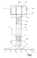
- Figure 1 a schematic representation of the principle of an endoscope and an instrument designed as a probe, which is guided through the working channel of the endoscope,
- Figure 2 an end portion of the probe Figure 1 that protrudes from the working channel of the endoscope in a schematic, block diagram-like representation
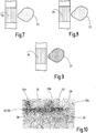
- Figure 6a a schematic representation of a modified embodiment of the end portion of a probe
- Figure 6b a schematic representation of a modified embodiment of the end section with a color marking that extends along the end section of a probe
- Figures 7-9 schematic basic representations of a color marking of a probe compared to the color of an application area of a treated tissue
- Figure 10 a photographic representation of an end section of a probe with a color marking and under several application areas on a tissue with different application dosages of the probe and
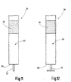
- Figures 11 and 12 each further exemplary embodiment of a probe in a schematic partial representation.
- the invention relates to an instrument for thermal and, for example, electrosurgical treatment of biological tissue 34.
- the instrument is designed as a probe 17, which is preferably set up for use with an endoscope 15.
- the endoscope 15 is illustrated in the manner of a block diagram.
- the endoscope 15 has an operating part 16 that can be handled by the surgeon.
- the probe 17 can be inserted into a working channel 18 of the endoscope 15.
- the working channel 18 has an opening from which at least a section of the probe 17 can be led out.
- a light source 20 and an objective 21 are arranged at the distal end of the endoscope 19 adjacent to the mouth of the working channel 18. The surroundings in front of the endoscope end 19 and in particular the tissue to be treated are illuminated via the light source 20.
- An image of the surroundings in front of the endoscope end 19 and in particular of the tissue to be treated is captured by means of the objective 21 and an optical system or camera.
- the camera and / or optics of the endoscope 15 forwards the images to an eyepiece and / or an external monitor.
- the instrument designed as a probe 17 has an instrument body 25 which, in the exemplary embodiment, is designed as an instrument hose 26 that can be bent transversely to its direction of extension when the forces that occur. Since the instrument is a probe 17, the instrument body 25 could also be referred to as a probe body and the instrument hose as a probe hose.
- the instrument body 25 and, for example, the instrument hose 26, extend from a proximal end 27 to a distal end 28. At the proximal end 27, the instrument hose 26 is connected to a supply and operating unit 29.
- the instrument and, for example, the probe 17 are set up for plasma coagulation, for example for argon plasma coagulation.
- the instrument could also be set up for cauterization or for carrying out another thermal treatment of biological tissue.
- the probe 17 has an electrode 32 in the region of the distal end 28 of the instrument body 25.
- the electrode 32 can be set up, for example, to be brought into direct contact with the biological tissue 34 to be treated.
- the electrode 32 is set up to carry out a thermal influence on the biological tissue 34 indirectly via an electrically conductive medium.
- a voltage, in particular a high-frequency alternating voltage, can be applied to the electrode 32.
- the electrode 32 is in the instrument body 25 via a running, not shown electrical line connected to an electrical connection, which is arranged in particular at the proximal end of the instrument or the probe.
- An electrical connection to the supply and operating unit 29 can be established via the electrical connection in order to be able to apply the voltage to the electrode 32.
- a fluid channel 30 is formed within the instrument body 25 or the instrument hose 26 ( Figure 2 ).
- a fluid G such as an inert gas, for example argon, can be introduced by means of the supply and operating unit 29.
- the fluid G flows through the fluid channel 30 to an outlet opening 31 in the region of the distal end 28 of the instrument hose 26.
- the electrode 32 is arranged inside the instrument hose 26 and adjacent to the outlet opening 31. As explained, the electrode 32 can be electrically connected to the supply and operating unit 29, so that a high-frequency alternating voltage can be applied to the electrode 32.
- the fluid can be ionized, for example an inert gas G, and a plasma 35 can be formed.
- a plasma 35 can be formed.
- the plasma is transmitted in direction E of the applied electrical field within an application area 33 to a tissue 34 to be treated.
- the energy input by means of the Plasma reaches a deep effect in the tissue 34 to be treated.
- the dosage of the energy input, in particular the duration of action or treatment, in the tissue 34 to be treated is particularly optimal when approximately two thirds of the desired depth effect is achieved during the treatment. Due to after-effects within about 72 hours after the treatment, the depth effect increases by the third that is still missing.
- a thermal or electrosurgical treatment and, for example, argon plasma coagulation of a tissue 34 to be treated can thus be carried out by means of the probe 17.
- Argon plasma coagulation is contactless. The probe 17 therefore does not touch the tissue 34 in the application area 33.
- the hue can be a brown hue, for example.
- the color of the color marking 39 corresponds to the color that the treated tissue 34 assumes in the application area 33 when the energy introduced by the selected dosage leads to the desired depth effect in the tissue 34.
- the color of the treated tissue 34 in the application area 33 is therefore an indicator of the depth effect achieved and the dosage, in particular the energy introduced per unit area.
- a visual comparison between the color of the color marking and the Color of the tissue 34 in the application area 33 can be carried out after the argon plasma coagulation. It can then be seen whether the correct dosage has been selected.
- the color of the color marking 39 is brown or brown-beige.
- the color of the at least one color marking 39 is the RAL color with the number 1011.
- the one color marking 39 or at least one of several color markings 39 has one or more contiguous colored areas. A single coherent colored area is sufficient.
- the one color marking 39 or at least one of several color markings 39 can optionally also have a texture and / or surface structure and / or matted surface.
- the real fabric structure can be better mapped and the comparison between the textured color marking 39 and the color and / or structure of the fabric 34 can be simplified.
- a rough and / or matt surface of the color marking 39 can prevent reflections, whereby the color comparison can be simplified.
- At least one color marking 39 is applied in the end section 38 to a jacket surface 40 or peripheral surface of the instrument hose 26, for example by a printing process.
- the color marking 39 can represent, for example, an annular surface that partially and preferably completely encloses the jacket surface 40.
- the at least one color marking 39 has a length of at least 2 mm or at least 3 mm.
- the length of the color marking 39 in the direction of extent of the end section 38 is preferably no greater than 5 mm or 6 mm or 7 mm or 10 mm.
- the at least one color marking 39 can also have any other configurations.
- the at least one color marking 39 can for example have at least one symbol and / or at least one character (number or letter) and / or at least one geometric figure.
- a company lettering and / or a company logo can thus also be used as color marking 39.
- Figure 6a the printing of a color marking 39 in the form of symbols is illustrated schematically.
- the illustrated end section 28 of a further exemplary embodiment of the probe 17 is at least one of the color markings 39 directly in the Connection to the distal end 28 attached to the lateral surface 40, for example printed.
- This color marking can be entirely or partially formed by a hollow cylindrical end piece 41.
- One or more further ring-shaped color markings, which, for example, are arranged at different distances from the distal end 28, can optionally be present.
- the one color marking 39 or all color markings 39 are arranged at a distance from the distal end 28 of the instrument tube 26.
- the instrument hose 26 preferably has a color that is optically contrasted with the surrounding tissue, so that the instrument hose 26 can be easily recognized during the operation and, for example, the endoscopic procedure. Due to the distance between the at least one color marking 39 and the distal end 28, the outlet opening 31 can be positioned at the required distance from the application area 33 of the tissue 34.
- a minimum distance d from the distal end 28 of the instrument hose 26 can be marked by means of the one color marking 39 or - if several color markings 39 are present - one of the existing color markings 39.
- an edge of the color marking 39, in particular the edge of the color marking 39 opposite the distal end 28 can be arranged at a point on the end section 38 of the instrument hose 26 which indicates the minimum distance d from the distal end 28.
- the color marking 39 or one of the color markings 39 can be arranged immediately following the distal end of the instrument body 25.
- the at least one color marking 39 can be at a distance from the distal end 28. Both variants have their own advantages.
- FIG. 3 corresponds to the in Figure 2 illustrated embodiment, in which the fluid G or the plasma is ejected as an extension of the end section 38.
- the instrument body 25 and, for example, the instrument hose 26 in the embodiments according to FIG Figures 4 and 5 an end piece 41 which has the outlet opening 31.
- the direction of the exiting fluid G or the plasma can be varied via the end piece 41.
- the fluid G or the plasma emerges essentially at right angles to the direction of extent of the end section 38 in all directions.
- the outlet opening 31 on the end piece 41 is the Figure 5 designed in such a way that the inert gas G or the plasma is specifically ejected laterally in one direction essentially at right angles to the direction of extent of the end section 38.
- FIGS 11 and 12 are shown schematically embodiments of the probe, in which the electrode 32 protrudes from the distal end 28 of the instrument body 25.
- These probes can be designed without a fluid channel 30.
- the electrode 32 can be brought into direct contact with the tissue 34 for thermal treatment or act on the tissue 34 by sparking without an additional medium.
- the end piece 41 can form a color marking 39.
- it can be colored in the defined brown color of the color marking 39 or completely or partially coated.
- the end piece 41 can, for example, be made of a ceramic material.
- the color of the fabric 34 in the application area 33 is according to Figure 9 darker than the color of the at least one color marking 39, so that there is an overdose.
- the fabric 34 was in the application area 33 damaged or impaired beyond the desired depth effect. The surgeon can recognize this and assess the consequences or, if necessary, initiate any necessary measures.
- a first application area 33a can be seen on the left in the picture, the color of which is darker than the color of the color marking 39. There is an overdose.
- the color in a second application area 33b essentially corresponds to the color of the at least one color marking 39.
- the correct dosage of the energy introduced was achieved.
- a third application area 33c which has a significantly lighter color than the color of the color marking 39, the energy input was underdosed. By further treatment of this third application area 33c, the desired dosage or depth effect can still be achieved.
- the invention relates to an instrument for the thermal treatment of tissue 34, in particular for electrosurgical treatment and in particular for argon plasma coagulation.
- the instrument has an instrument body 25 extending between a proximal end 27 and a distal end 28. In an end section 38 adjacent to the distal end 28, the instrument body 25 has at least one color marking 39 in a defined color. This color corresponds to the color of a treated tissue 34, which arises when the dosage of an energy input to achieve a desired depth effect in the tissue 34 has been selected correctly.
- the instrument is preferably designed as a probe 17, in particular as an endoscope probe, and has a flexibly bendable instrument body 25, which can be referred to as an instrument hose 26.
Abstract
Die Erfindung betrifft ein Instrument zur thermischen Behandlung von Gewebe (34), ins besondere zur elektrochirurgischen Behandlung und insbesondere zur Argonplasma-Koagulation. Das Instrument hat einen sich zwischen einem proximalen Ende (27) und einem distalen Ende (28) erstreckenden Instrumentenkörper (25). In einem Endabschnitt (38) angrenzend an das distale Ende (28) weist der Instrumentenkörper (25) wenigstens eine Farbmarkierung (39) in einer definierten Farbe auf. Diese Farbe entspricht der Farbe eines behandelten Gewebes (34), die entsteht, wenn die Dosierung eines Energieeintrags zur Erzielung einer gewünschten Tiefenwirkung im Gewebe (34) korrekt gewählt wurde. Vorzugsweise ist das Instrument als Sonde (17), insbesondere als Endoskopsonde, ausgebildet und hat einen flexibel biegbaren Instrumentenkörper (25), der als Instrumentenschlauch (26) bezeichnet werden kann.The invention relates to an instrument for the thermal treatment of tissue (34), in particular for electrosurgical treatment and in particular for argon plasma coagulation. The instrument has an instrument body (25) extending between a proximal end (27) and a distal end (28). In an end section (38) adjoining the distal end (28), the instrument body (25) has at least one color marking (39) in a defined color. This color corresponds to the color of a treated tissue (34), which arises when the dosage of an energy input to achieve a desired depth effect in the tissue (34) has been selected correctly. The instrument is preferably designed as a probe (17), in particular as an endoscope probe, and has a flexibly bendable instrument body (25) which can be referred to as an instrument hose (26).
Description
Die Erfindung betrifft ein Instrument, insbesondere eine Sonde oder endoskopische Sonde, das zur thermischen Behandlung, beispielsweise elektrochirurgischen Behandlung von Gewebe eingerichtet ist. Das Instrument bzw. die Sonde kann mittels eines festen Körpers oder auch mittels eines Plasmas thermisch auf das Gewebe einwirken. Das Instrument kann beispielsweise zur Kauterisierung oder zur Plasma-Koagulation, insbesondere der Argonplasma-Koagulation eingerichtet sein.The invention relates to an instrument, in particular a probe or endoscopic probe, which is set up for thermal treatment, for example electrosurgical treatment of tissue. The instrument or the probe can act thermally on the tissue by means of a solid body or also by means of a plasma. The instrument can be set up, for example, for cauterization or for plasma coagulation, in particular argon plasma coagulation.
Ein derartiges Instrument ist beispielsweise aus
Bei der thermischen und insbesondere elektrochirurgischen Behandlung von Gewebe ist die Dosierung der Behandlung für den Operateur häufig schwierig abzuschätzen, also wie lange das Gewebe im Applikationsbereich thermisch behandelt werden muss bzw. welche Energie pro Flächeneinheit eingetragen werden muss, um die gewünschte Tiefenwirkung zu erreichen. Das Gewebe darf weder zu kurz, noch zu lang behandelt werden, um eine Unterdosierung bzw. Überdosierung zu vermeiden und den gewünschten Effekt, insbesondere die gewünschte Tiefenwirkung zu erzielen.In the thermal and, in particular, electrosurgical treatment of tissue, the dosage of the treatment is often difficult for the surgeon to estimate, i.e. how long the tissue in the application area must be thermally treated or what energy must be entered per unit area in order to achieve the desired depth effect. The tissue must not be treated for too short or too long in order to avoid underdosing or overdosing and to achieve the desired effect, in particular the desired depth effect.
Ausgehend hiervon ist es eine Aufgabe der vorliegenden Erfindung eine Sonde zu schaffen, die das Dosieren, insbesondere das Abschätzen der Dauer der Behandlung im Applikationsbereich vereinfacht.Based on this, it is an object of the present invention to create a probe which simplifies the dosing, in particular the estimation of the duration of the treatment in the application area.
Diese Aufgabe wird durch eine Sonde mit den Merkmalen des Patentanspruches 1 gelöst.This object is achieved by a probe with the features of
Das Instrument bzw. die Sonde ist zur thermischen Behandlung von Gewebe eingerichtet. Das Gewebe wird in einem Applikationsbereich, insbesondere mittels eines Plasmas behandelt. Vorzugsweise ist das Instrument bzw. die Sonde zur elektrochirurgischen Koagulation eingerichtet, insbesondere zur Argonplasma-Koagulation.The instrument or the probe is set up for the thermal treatment of tissue. The tissue is treated in an application area, in particular by means of a plasma. The instrument or the probe is preferably set up for electrosurgical coagulation, in particular for argon plasma coagulation.
Das Instrument weist einen Instrumentenkörper auf, der abhängig von der Ausführung des Instruments bzw. der Sonde durch einen bei den üblicherweise auftretenden Kräften nicht biegbaren, starren Rohrkörper oder durch einen flexiblen Schlauchkörper gebildet sein kann. Der Instrumentenkörper erstreckt sich von einem proximalen Ende zu einem distalen Ende. Am proximalen Ende kann der Instrumentenkörper an eine Versorgungs- und Bedieneinheit angeschlossen werden.The instrument has an instrument body which, depending on the design of the instrument or the probe, can be formed by a rigid tubular body that cannot be bent under the forces that usually occur or by a flexible hose body. The instrument body extends from a proximal end to a distal end. At the proximal end, the instrument body can be connected to a supply and control unit.
Das Instrument weist im Bereich des distalen Endes des Instrumentenkörpers eine Elektrode auf, an die eine Spannung, insbesondere eine hochfrequente Wechselspannung, angelegt werden kann. Die Elektrode kann über eine im Instrumentenkörper verlaufende elektrische Leitung mit einem elektrischen Anschluss verbunden sein, der insbesondere am proximalen Ende des Instruments bzw. der Sonde angeordnet ist. Eine Versorgungsleitung einer Versorgungs- uns Bedieneinheit kann mit dem elektrischen Anschluss verbunden werden, um die Spannung an die Elektrode anlegen zu können.In the area of the distal end of the instrument body, the instrument has an electrode to which a voltage, in particular a high-frequency alternating voltage, can be applied. The electrode can be connected to an electrical connection via an electrical line running in the instrument body, which connection is arranged in particular at the proximal end of the instrument or the probe is. A supply line of a supply and control unit can be connected to the electrical connection in order to be able to apply the voltage to the electrode.
Mittels der Elektrode kann durch unmittelbaren Kontakt (z.B. bei der Kauterisierung) oder mittelbar über ein elektrisch leitfähiges Medium (z.B. bei der Koagulation) eine thermische Beeinflussung des Gewebes erfolgen.By means of the electrode, the tissue can be thermally influenced by direct contact (e.g. during cauterization) or indirectly via an electrically conductive medium (e.g. during coagulation).
Bei einem Ausführungsbeispiel ist das Instrument bzw. die Sonde zur Plasma-Koagulation, insbesondere der Argonplasma-Koagulation, eingerichtet. Dann kann in dem Instrumentenkörper ein Fluidkanal gebildet sein, der fluidisch mit einer Austrittsöffnung im Bereich des distalen Endes verbunden ist. Vorzugsweise ist die Elektrode im Bereich der Austrittsöffnung innerhalb des Instrumentenkörpers angeordnet. Die Elektrode wird von einem Fluid, insbesondere einem Inertgas, einem Gasgemisch, oder einem dem Inertgas beigefügten Zusatzstoff umspült.In one embodiment, the instrument or the probe is set up for plasma coagulation, in particular argon plasma coagulation. A fluid channel can then be formed in the instrument body which is fluidically connected to an outlet opening in the region of the distal end. The electrode is preferably arranged in the region of the outlet opening within the instrument body. The electrode is surrounded by a fluid, in particular an inert gas, a gas mixture, or an additive added to the inert gas.
Bei dieser Ausgestaltung des Instruments kann in einem bevorzugten Anwendungsfall das aus der Austrittsöffnung austretende Fluid, insbesondere das Inertgas, mittels der Elektrode ionisiert werden und in einen elektrisch leitfähigen Aggregatzustand gebracht werden, indem es beispielsgemäß in ein Plasma überführt wird. Das Fluid wird im Applikationsbereich auf das Gewebe gerichtet. Aufgrund des elektrisch leitfähigen Aggregatszustandes des ausströmenden ionisierten Fluids wird Energieauf das Gewebe übertragen. Zur Ionisierung des Fluids, insbesondere des Argongases wird an die Elektrode eine hochfrequente Wechselspannung angelegt, die dem Instrument über die Versorgungs- und Bedieneinheit bereitgestellt werden kann. Das Ionisieren des Inertgases erfolgt im Bereich unmittelbar vor der Austrittsöffnung.In this embodiment of the instrument, in a preferred application, the fluid emerging from the outlet opening, in particular the inert gas, can be ionized by means of the electrode and brought into an electrically conductive aggregate state by, for example, being converted into a plasma. The fluid is directed onto the tissue in the application area. Due to the electrically conductive aggregate state of the outflowing ionized fluid, energy is transferred to the tissue. To ionize the fluid, in particular the argon gas, a high-frequency alternating voltage is applied to the electrode, which can be made available to the instrument via the supply and operating unit. Ionizing the Inert gas occurs in the area immediately in front of the outlet opening.
In einem Anwendungsfall wird die über die Elektrode geleitete Energie in den Applikationsbereich auf das Gewebe übertragen, beispielsweise mittels Kontakt der Elektrode zum Gewebe. Die an der Elektrode übertragene Energie wird über eine hochfrequente Wechselspannung realisiert, die dem Instrument über die Versorgungs- und Bedieneinheit bereitgestellt werden kann.In one application, the energy conducted via the electrode is transferred to the application area on the tissue, for example by means of contact between the electrode and the tissue. The energy transferred to the electrode is realized via a high-frequency alternating voltage, which can be made available to the instrument via the supply and control unit.
Im Bereich des distalen Endes ist am Instrumentenkörper wenigstens eine Farbmarkierung angeordnet, die eine definierte Farbe bzw. einen definierten Farbton und/oder eine definierte Farbsättigung und/oder eine definierte Helligkeit hat, wobei die Farbe beispielsweise braun, braunbeige oder rot sein kann. Die wenigstens eine Farbmarkierung ist von außen sichtbar angeordnet und kann beispielsweise einen farbigen Aufdruck und/oder einen farbigen Einsatz aufweisen. Zusätzlich oder alternativ kann auch ein Bestandteil des Instrumentenkörpers in der gewählten oder definierten Farbe hergestellt und/oder zumindest teilweise gefärbt oder bedruckt sein, wie zum Beispiel ein die Austrittsöffnung aufweisendes Endstück. Die wenigstens eine Farbmarkierung kann vorzugsweise auf einer Mantelfläche des Instrumentenkörpers angebracht sein.In the area of the distal end, at least one color marking is arranged on the instrument body, which has a defined color or a defined hue and / or a defined color saturation and / or a defined brightness, the color being, for example, brown, brown-beige or red. The at least one color marking is arranged so as to be visible from the outside and can, for example, have a colored print and / or a colored insert. Additionally or alternatively, a component of the instrument body can also be produced in the selected or defined color and / or at least partially colored or printed, such as an end piece having the outlet opening. The at least one color marking can preferably be applied to a lateral surface of the instrument body.
Die wenigstens eine Farbmarkierung kann wenigstens ein Symbol und/oder wenigstens ein Zeichen (Ziffer und/oder Buchstabe) und/oder wenigstens eine geometrische Figur, wie zum Beispiel ein Logo und/oder einen Barcode aufweisen. Beispielsweise kann wenigstens ein farbiger Ring als Farbmarkierung dienen. Die Farbmarkierung oder zumindest eine der Farbmarkierungen ist vorzugsweise durch eine zusammenhängende, vollständig gefüllte Fläche in der gewählten bzw. definierten Farbe gebildet.The at least one color marking can have at least one symbol and / or at least one character (number and / or letter) and / or at least one geometric figure, such as a logo and / or a barcode. For example, at least one colored ring serve as a color marker. The color marking or at least one of the color markings is preferably formed by a coherent, completely filled area in the selected or defined color.
Die Farbe der Farbmarkierung ist so gewählt, dass sie der Farbe eines behandelten Gewebes mit der gewünschten Dosierung und/oder Tiefenwirkung der Behandlung entspricht. Das heißt, die Farbmarkierung dient zum Farbvergleich mit der Färbung des behandelten Gewebes und die Färbung des behandelten Gewebes ist der Farbe der Farbmarkierung dann am ähnlichsten, wenn die gewünschte Dosierung bzw. Tiefenwirkung erreicht wurde. Ein Operateur kann daher unmittelbar durch Farbvergleich zwischen der Farbmarkierung und einem behandelten Gewebe erkennen, ob die Dosierung bzw. Einwirkungsdauer richtig gewählt wurde und somit einen Rückschluss auf die erzielte Tiefenwirkung ziehen. Für einen typischen Anwendungsfall gilt: ist die Farbe des behandelten Gewebes heller als die Farbe der Farbmarkierung, wurde die Behandlung nicht ausreichend lang durchgeführt. Ist die Farbe des behandelten Gewebes dunkler als die Farbe der Farbmarkierung, wurde die Behandlung überdosiert, insbesondere bei zu langer Behandlung des Gewebes. Sind die Farbe des behandelten Gewebes und der Farbmarkierung gleich, wurde die richtige Dosierung und Behandlungsdauer durchgeführt und die gewünschte Tiefenwirkung im Gewebe erreicht. Bei anderen Anwendungsfällen kann die Farbänderung auch abweichend sein vom beschriebenen typischen Anwendungsfall. Jedenfalls gibt die wenigstens eine Farbmarkierung die Farbe an, bei der für den betreffenden Anwendungsfall die gewünschte Dosierung bzw. Tiefenwirkung im Gewebe erreicht wurde.The color of the color marking is chosen so that it corresponds to the color of a treated tissue with the desired dosage and / or depth of treatment. This means that the color marking is used to compare the color with the coloring of the treated tissue and the coloring of the treated tissue is most similar to the color of the color marking when the desired dosage or depth effect has been achieved. A surgeon can therefore immediately see by comparing the colors between the color marking and a treated tissue whether the correct dosage or exposure time has been selected and thus draw a conclusion about the depth effect achieved. For a typical application, the following applies: if the color of the treated fabric is lighter than the color of the color marking, the treatment was not carried out for a sufficiently long time. If the color of the treated tissue is darker than the color of the color marking, the treatment has been overdosed, especially if the tissue has been treated for too long. If the color of the treated tissue and the color marking are the same, the correct dosage and duration of treatment have been carried out and the desired depth effect in the tissue has been achieved. In other applications, the color change can also differ from the typical application described. In any case, the at least one color marking indicates the color in which the desired dosage or depth effect in the tissue was achieved for the application in question.
Die Farbe der Farbmarkierung ist vorzugsweise braun oder braunbeige. Die Farbe, der Farbton oder ein anderes Farbmerkmal kann insbesondere abhängig von der Art der Behandlung und von dem zu behandelnden Gewebetyp ausgewählt werden. Bei einer Ausführungsform ist die Farbe der wenigstens einen Farbmarkierung eine RAL-Farbe. Je nach klinischer Indikation und Behandlungsgebiet bzw. Gewebetyp können für die wenigstens eine Farbmarkierung beispielsweise RAL-Farben mit den RAL-Nummern 1001, 1005, 1011, 1024, 8001, 8003, 8007 oder 8011 verwendet werden. Es hat sich gezeigt, dass diese RAL-Farben die Farbtöne des mit der richtigen Dosierung behandelten Gewebes sehr gut wiedergibt, wobei eine der RAL-Farben ausgewählt wird abhängig von der Art der Behandlung und von dem zu behandelnden Gewebetyp. Außerdem ist die RAL-Farbe genau definiert und lässt sich bei der Herstellung von Sonden sehr gut reproduzieren.The color of the color marking is preferably brown or brown-beige. The color, the hue or another color characteristic can be selected in particular depending on the type of treatment and on the type of tissue to be treated. In one embodiment, the color of the at least one color marking is a RAL color. Depending on the clinical indication and treatment area or tissue type, RAL colors with the RAL numbers 1001, 1005, 1011, 1024, 8001, 8003, 8007 or 8011, for example, can be used for the at least one color marking. It has been shown that these RAL colors reproduce the color tones of the fabric treated with the correct dosage very well, one of the RAL colors being selected depending on the type of treatment and the type of fabric to be treated. In addition, the RAL color is precisely defined and can be reproduced very well in the manufacture of probes.
Um dem Operateur einen ausreichend genauen Vergleich zu gestatten, ist es vorteilhaft, wenn die Farbmarkierung ausreichend groß ist. Bevorzugt ist die Farbmarkierung flächig und weist bevorzugt eine Gesamtfläche von mindestens 15 mm2 oder mindestens 20 mm2 auf. Zusätzlich oder alternativ kann die Farbmarkierung in Erstreckungsrichtung des Instrumentenkörpers mindestens 2 mm oder mindestens 3 mm oder mindestens 5 mm lang sein. Es ist weiter bevorzugt, wenn die angegebene Gesamtfläche der Farbmarkierung als zusammenhängende Fläche ausgebildet und vorzugsweise vollständig mit der definierten Farbe ausgefüllt ist.In order to allow the surgeon to make a sufficiently precise comparison, it is advantageous if the color marking is sufficiently large. The color marking is preferably flat and preferably has a total area of at least 15 mm 2 or at least 20 mm 2 . Additionally or alternatively, the color marking can be at least 2 mm or at least 3 mm or at least 5 mm long in the direction of extent of the instrument body. It is further preferred if the specified total area of the color marking is designed as a cohesive area and is preferably completely filled with the defined color.
Bei einer bevorzugten Ausführungsform ist die eine Farbmarkierung oder ist wenigstens eine von mehreren Farbmarkierungen an einer Mantelfläche des Instrumentenkörpers vorhanden, insbesondere in Form eines Aufdrucks. Diese eine Farbmarkierung kann hier die Form von wenigstens einem Streifen oder Ring aufweisen.In a preferred embodiment, the one color marking or is at least one of several Color markings are present on a lateral surface of the instrument body, in particular in the form of an imprint. This one color marking can here have the form of at least one strip or ring.
Bei einer bevorzugten Ausführungsform ist die eine Farbmarkierung oder ist wenigstens eine von mehreren Farbmarkierung an einer Mantelfläche des Instrumentenkörpers vorhanden, insbesondere in Form einer zumindest teilweise umlaufenden Fläche, wie zum Beispiel eines umlaufenden Rings und/oder zwei oder mehreren Streifen. Es ist vorteilhaft, wenn sich diese wenigstens eine Farbmarkierung in einer Umfangsrichtung um den Instrumentenkörper erstreckt, zumindest um 50% des Umfangs des Instrumentenkörpers. Vorzugsweise erstreckt sich die wenigstens eine Farbmarkierung vollständig um den Umfang des Sondenkörpers herum und weist die Form einer geschlossenen Ringfläche auf.In a preferred embodiment, the one color marking or at least one of several color marking is present on a lateral surface of the instrument body, in particular in the form of an at least partially circumferential surface, such as a circumferential ring and / or two or more strips. It is advantageous if this at least one colored marking extends in a circumferential direction around the instrument body, at least by 50% of the circumference of the instrument body. The at least one color marking preferably extends completely around the circumference of the probe body and has the shape of a closed annular surface.
Bevorzugt weist der Instrumentenkörper außerhalb der wenigstens einen Farbmarkierung eine Farbe oder mehrere Farben auf, die sich von der Farbe der wenigstens einen Farbmarkierung unterscheidet bzw. unterscheiden, und die sich insbesondere optisch vom Gewebe abhebt. Dadurch wird die Sichtbarkeit des Instruments bzw. der Sonde für den Operateur verbessert. Beispielsweise kann der Instrumentenkörper außerhalb bzw. umgebend zu der wenigstens einen Farbmarkierung blau sein. Die die wenigstens eine Farbmarkierung umgebende Farbe des Instrumentenkörpers ist bevorzugt dunkler als die Farbe der wenigstens einen Farbmarkierung.Outside of the at least one color marking, the instrument body preferably has one or more colors which differ or differ from the color of the at least one color marking and which, in particular, stands out optically from the tissue. This improves the visibility of the instrument or the probe for the surgeon. For example, the instrument body can be blue outside or surrounding the at least one color marking. The color of the instrument body surrounding the at least one color marking is preferably darker than the color of the at least one color marking.
Es ist bevorzugt, wenn die wenigstens eine Farbmarkierung nicht bis zum distalen Ende des Instrumentenkörpers reicht, sondern mit Abstand dazu angeordnet ist.It is preferred if the at least one color marking does not extend to the distal end of the instrument body, but is arranged at a distance from it.
Es ist außerdem bevorzugt, wenn die wenigstens eine Farbmarkierung eine Markierung darstellt, die einen definierten Abstand oder Mindestabstand zum distalen Ende angibt. Dadurch kann dem Operateur angezeigt werden, wann der Instrumentenkörper bzw. das distale Ende weit genug aus einem Endoskop herausgeschoben wurde, um beim Applizieren des Plasmas die Optik des Endoskops nicht zu beschädigen oder zu beeinträchtigen. Beispielsweise kann der am weitesten entfernte Rand der wenigstens einen Farbmarkierung einen Mindestabstand zum distalen Ende angeben. Erst wenn die wenigstens eine Farbmarkierung vollständig durch eine Optik eines Endoskops zu erkennen ist, befindet sich das distale Ende des Instrumentenkörpers weit genug vom Endoskop weg, um eine Behandlung auszuführen.It is also preferred if the at least one color marking represents a marking which indicates a defined distance or minimum distance from the distal end. This enables the surgeon to be shown when the instrument body or the distal end has been pushed out of an endoscope far enough not to damage or impair the optics of the endoscope when the plasma is applied. For example, the most distant edge of the at least one color marking can indicate a minimum distance from the distal end. Only when the at least one color marking can be fully recognized through the optics of an endoscope is the distal end of the instrument body far enough away from the endoscope to carry out a treatment.
Bei einem Ausführungsbeispiel weist der Instrumentenkörper ein Endstück auf, das die Austrittsöffnung aufweist. Das Endstück kann beispielsweise dazu eingerichtet sein, die Ausströmrichtung des Fluids bzw. des Plasmas vorzugeben. Das Endstück kann vollständig oder teilweise in der definierten Farbe der Farbmarkierung ausgeführt sein, so dass das Endstück zumindest eine der Farbmarkierungen bildet.In one embodiment, the instrument body has an end piece that has the outlet opening. The end piece can be set up, for example, to specify the outflow direction of the fluid or the plasma. The end piece can be designed completely or partially in the defined color of the color marking, so that the end piece forms at least one of the color markings.
Die wenigstens eine Farbmarkierung oder wenigstens eine von mehreren Farbmarkierungen kann auch eine Textur und/oder Oberflächenstruktur und/oder mattierte und/oder nicht spiegelnde Oberfläche aufweisen. Dadurch kann die reale Gewebestruktur besser abgebildet und der Vergleich zwischen der texturierten Farbmarkierung und der Farbe und/oder Struktur des Gewebes vereinfacht werden. Außerdem kann eine raue und/oder matte und/oder nicht spiegelnde Oberfläche der Farbmarkierung Lichtspiegelungen verhindern. Die Oberfläche kann dabei vorzugsweise eine Rauheit aufweisen, die eienr der VDI-Klassen 33 - 42 der VDI-Richtlinie 3400 (Oberflächenvergleichsmustermessung) entspricht. Die Oberfläche kann eine maximalen Rautiefe Rmax = 18 - 49 µm, insbesondere Rmax = 25 µm aufweisen und/oder einen arithmetischen Mittenrauwert Ra = 4,5 - 12,5 µm, insbesondere Ra = 6,3 µm aufweisen.The at least one color marking or at least one of several color markings can also have a texture and / or surface structure and / or matt and / or non-reflective surface. As a result, the real tissue structure can be better mapped and the comparison between the textured color marking and the color and / or structure of the fabric can be simplified. In addition, a rough and / or matt and / or non-reflective surface of the color marking can prevent light reflections. The surface can preferably have a roughness that corresponds to one of VDI classes 33-42 of VDI guideline 3400 (surface comparison sample measurement). The surface can have a maximum roughness depth Rmax = 18-49 µm, in particular Rmax = 25 µm and / or an arithmetic mean roughness value Ra = 4.5-12.5 µm, in particular Ra = 6.3 µm.
Die vorstehend erläuterten Ausgestaltungen der wenigstens einen Farbmarkierung können beliebig miteinander kombiniert werden. Beispielsweise kann sowohl ein Endstück des Instrumentenkörpers als eine Farbmarkierung dienen, als auch zusätzlich an der Mantelfläche des Instrumentenkörpers eine oder mehrere weitere farbige Flächen, Symbole, Zeichen oder dergleichen vorhanden sein. Bei einer bevorzugten Ausführungsform ist die wenigstens eine Farbmarkierung ausschließlich außen auf der Mantelfläche des Instrumentenkörpers vorhanden. In diesem Fall können die Instrumentenkörper unabhängig von der Art und Ausgestaltung der Austrittsöffnung bei der Herstellung von Sonden als Gleichteil verwendet werden. Dadurch lassen sich Skalierungseffekte erreichen.The configurations of the at least one color marking explained above can be combined with one another as desired. For example, both an end piece of the instrument body can serve as a color marking and one or more additional colored areas, symbols, characters or the like can also be present on the outer surface of the instrument body. In a preferred embodiment, the at least one color marking is only present on the outside on the lateral surface of the instrument body. In this case, the instrument bodies can be used as identical parts in the manufacture of probes, regardless of the type and configuration of the outlet opening. This enables scaling effects to be achieved.
Bei einem Ausführungsbeispiel ist der Instrumentenkörper als Instrumentenschlauch ausgebildet. Der Instrumentenschlauch ist quer zu seiner Erstreckungsrichtung bei den auftretenden Kräften flexibel bzw. biegbar. Vorzugsweise ist der Instrumentenschlauch dazu eingerichtet, durch einen Arbeitskanal eines Endoskops geführt zu werden.In one embodiment, the instrument body is designed as an instrument hose. The instrument hose is flexible or bendable transversely to its direction of extension under the forces that occur. The instrument hose is preferably designed to be guided through a working channel of an endoscope.
Vorteilhafte Ausgestaltungen der Erfindung ergeben sich aus den abhängigen Ansprüchen, der Beschreibung und den Zeichnungen. Nachfolgend werden bevorzugte Ausführungsbeispiele der Erfindung anhand der beigefügten Zeichnungen im Einzelnen erläutert. Es zeigen:Advantageous embodiments of the invention emerge from the dependent claims, the description and the drawings. Preferred exemplary embodiments of the invention are explained in detail below with reference to the accompanying drawings. Show it:
Die Erfindung betrifft ein Instrument zur thermischen uns beispielsweise zur elektrochirurgischen Behandlung von biologischem Gewebe 34. Bei den nachfolgend anhand der Zeichnungen veranschaulichen Ausführungsformen ist das Instrument als Sonde 17 ausgebildet, die vorzugsweise zur Verwendung mit einem Endoskop 15 eingerichtet ist.The invention relates to an instrument for thermal and, for example, electrosurgical treatment of
In
Das als Sonde 17 ausgeführte Instrument hat einen Instrumentenkörper 25, der beim Ausführungsbeispiel als quer zu seiner Erstreckungsrichtung bei den auftretenden Kräften biegbarer Instrumentenschlauch 26 ausgebildet ist. Da es sich bei dem Instrument um eine Sonde 17 handelt, könnte der Instrumentenkörper 25 auch als Sondenkörper und der Instrumentenschlauch als Sondenschlauch bezeichnet werden. Der Instrumentenkörper 25 und beispielsgemäß der Instrumentenschlauch 26 erstreckt sich von einem proximalen Ende 27 bis zu einem distalen Ende 28. An dem proximalen Ende 27 ist der Instrumentenschlauch 26 an eine Versorgungs- und Bedieneinheit 29 angeschlossen.The instrument designed as a
Das Instrument und beispielsgemäß die Sonde 17 ist bei den veranschaulichten Ausführungsformen zur Plasma-Koagulation, beispielsgemäß zur Argonplasma-Koagulation eingerichtet. Alternativ dazu könnte das Instrument auch zur Kauterisierung oder zur Durchführung einer anderen thermischen Behandlung von biologischem Gewebe eingerichtet sein.In the illustrated embodiments, the instrument and, for example, the
Die Sonde 17 weist im Bereich des distalen Endes 28 des Instrumentenkörpers 25 eine Elektrode 32 auf. Die Elektrode 32 kann beispielsweise dazu eingerichtet sein, unmittelbar in Kontakt mit dem zu behandelnden biologischen Gewebe 34 gebracht zu werden. Beim bevorzugten Ausführungsbeispiel ist die Elektrode 32 dazu eingerichtet, mittelbar über ein elektrisch leitfähiges Medium eine thermische Beeinflussung des biologischen Gewebes 34 durchzuführen.The
An die Elektrode 32 kann eine Spannung, insbesondere eine hochfrequente Wechselspannung, angelegt werden. Die Elektrode 32 ist über eine im Instrumentenkörper 25 verlaufende, nicht dargestellte elektrische Leitung mit einem elektrischen Anschluss verbunden, der insbesondere am proximalen Ende des Instruments bzw. der Sonde angeordnet ist. Über den elektrischen Anschluss kann eine elektrische Verbindung zur Versorgungs- uns Bedieneinheit 29 hergestellt werden, um die Spannung an die Elektrode 32 anlegen zu können.A voltage, in particular a high-frequency alternating voltage, can be applied to the
Bei der Ausgestaltung der Sonde 17 zur Plasma-Koagulation ist innerhalb des Instrumentenkörpers 25 bzw. des Instrumentenschlauchs 26 ist ein Fluidkanal 30 gebildet (
Innerhalb des Instrumentenschlauchs 26 und benachbart zur Austrittsöffnung 31 ist die Elektrode 32 angeordnet. Wie erläutert ist die Elektrode 32 elektrisch mit der Versorgungs- und Bedieneinheit 29 verbindbar, so dass eine hochfrequente Wechselspannung an die Elektrode 32 angelegt werden kann. Mittels der hochfrequenten Wechselspannung kann das Fluid bspw. ein Inertgas G ionisiert und ein Plasma 35 gebildet werden. Wie es stark schematisiert in
Mittels der Sonde 17 kann somit eine thermische bzw. elektrochirurgische Behandlung und beispielsgemäß eine Argonplasma-Koagulation eines zu behandelnden Gewebes 34 ausgeführt werden. Die Argonplasma-Koagulation ist kontaktlos. Die Sonde 17 berührt das Gewebe 34 im Applikationsbereich 33 somit nicht.A thermal or electrosurgical treatment and, for example, argon plasma coagulation of a
In einem Endabschnitt 38 des Instrumentenkörpers 25 und beispielsgemäß des Instrumentenschlauchs 26 im Anschluss an sein distales Ende 28 ist wenigstens eine Farbmarkierung 39 vorhanden, die eine Farbe mit einem definierten Farbton und/oder einer definierten Farbsättigung und/oder einer definierten Helligkeit aufweist. Der Farbton kann beispielsweise ein Braun-Farbton sein. Die Farbe der Farbmarkierung 39 entspricht der Farbe, die das behandelte Gewebe 34 im Applikationsbereich 33 annimmt, wenn die durch die gewählte Dosierung eingetragene Energie zu der gewünschten Tiefenwirkung im Gewebe 34 führt. Die Farbe des behandelten Gewebes 34 im Applikationsbereich 33 ist daher ein Indikator für die erreichte Tiefenwirkung und die Dosierung, insbesondere die pro Flächeneinheit eingetragene Energie. Anhand der Farbmarkierung 39 kann ein optischer Vergleich zwischen der Farbe der Farbmarkierung und der Farbe des Gewebes 34 im Applikationsbereich 33 nach der Argonplasma-Koagulation durchgeführt werden. Es ist dann erkennbar, ob die Dosierung korrekt gewählt wurde.In an
Beispielsgemäß ist die Farbe der Farbmarkierung 39 braun oder braunbeige. Beim Ausführungsbeispiel ist die Farbe der wenigstens einen Farbmarkierung 39 die RAL-Farbe mit der Nummer 1011.According to the example, the color of the color marking 39 is brown or brown-beige. In the exemplary embodiment, the color of the at least one color marking 39 is the RAL color with the number 1011.
Die eine Farbmarkierung 39 oder wenigstens eine von mehreren Farbmarkierungen 39 weist eine oder mehrere zusammenhängende Farbflächen auf. Eine einzige zusammenhängende Farbfläche ist ausreichend.The one color marking 39 or at least one of
Die eine Farbmarkierung 39 oder wenigstens eine von mehreren Farbmarkierungen 39 kann optional auch eine Textur und/oder Oberflächenstruktur und/oder mattierte Oberfläche aufweisen. Dadurch kann die reale Gewebestruktur besser abgebildet und der Vergleich zwischen der texturierten Farbmarkierung 39 und der Farbe und/oder Struktur des Gewebes 34 vereinfacht werden. Außerdem kann eine raue und/oder matte Oberfläche der Farbmarkierung 39 Spiegelungen verhindern, wodurch der Farbvergleich vereinfacht werden kann.The one color marking 39 or at least one of
Sofern die eine Farbmarkierung 39 oder wenigstens eine von mehreren Farbmarkierung 39 eine oder mehrere Texturen aufweist, so können diese in Anlehnung an die VDI 3400 (Oberflächenvergleichsmustermessung) die VDI-Klassen 33 - 42 mit der maximalen Rautiefe Rmax = 18 - 49 µm und dem arithmetischen Mittenrauwert Ra = 4,5 - 12,5 µm, insbesondere die VDI-Klasse 36, Rmax = 25 µm, Ra = 6,3 µm ausgeführt werden.If the one color marking 39 or at least one of several color marking 39 has one or more textures, these can be based on VDI 3400 (surface comparison pattern measurement), VDI classes 33 - 42 with the maximum roughness depth Rmax = 18 - 49 μm and the arithmetic Average roughness value Ra = 4.5 - 12.5 µm, especially VDI class 36, Rmax = 25 µm, Ra = 6.3 µm.
Beim Ausführungsbeispiel ist zumindest eine Farbmarkierung 39 im Endabschnitt 38 auf eine Mantelfläche 40 bzw. Umfangsfläche des Instrumentenschlauchs 26 aufgebracht, beispielsweise durch ein Druckverfahren. Die Farbmarkierung 39 kann zum Beispiel eine die Mantelfläche 40 teilweise und vorzugsweise vollständig umschließende Ringfläche darstellen. In Erstreckungsrichtung des Instrumentenschlauchs 26 bzw. des Endabschnitts 38 weist die wenigstens eine Farbmarkierung 39 eine Länge von mindestens 2 mm oder mindestens 3 mm auf. Vorzugsweise ist die Länge der Farbmarkierung 39 in Erstreckungsrichtung des Endabschnitts 38 nicht größer als 5 mm oder 6 mm oder 7 mm oder 10 mm.In the exemplary embodiment, at least one color marking 39 is applied in the
An dem Instrumentenschlauch 26 und insbesondere an der Mantelfläche 40 können weitere Markierungen für einen Operateur vorhanden sein, die in beliebigen Farben und Formen ausgestaltet werden können.Further markings for a surgeon, which can be designed in any desired colors and shapes, can be present on the instrument hose 26 and in particular on the
Anstelle einer Ringfläche kann die wenigstens eine Farbmarkierung 39 auch beliebige andere Ausgestaltungen aufweisen. Die wenigstens eine Farbmarkierung 39 kann beispielsweise wenigstens ein Symbol und/oder wenigstens ein Zeichen (Ziffer oder Buchstabe) und/oder wenigstens eine geometrische Figur aufweisen. Somit können auch ein Firmenschriftzug und/oder ein Firmenlogo als Farbmarkierung 39 verwendet werden. In
Bei dem in
Beim Ausführungsbeispiel der Sonde 17 gemäß der
Mittels der einen Farbmarkierung 39 oder - sofern mehrere Farbmarkierungen 39 vorhanden sind - einer der vorhandenen Farbmarkierungen 39 kann ein Mindestabstand d vom distalen Ende 28 des Instrumentenschlauchs 26 markiert werden. Beispielsweise kann ein Rand der Farbmarkierung 39, insbesondere der dem distalen Ende 28 entgegengesetzte Rand der Farbmarkierung 39 an einer Stelle des Endabschnitts 38 des Instrumentenschlauchs 26 angeordnet sein, der dem Mindestabstand d zum distalen Ende 28 angibt. Beim Endoskopieren kann der Operateur erkennen, ob die Sonde 17 bzw. deren Endabschnitt 38 weit genug aus dem Arbeitskanal 18 des Endoskops 15 herausgeschoben wurde, um während der Behandlung des Gewebes 34 das Endoskop 15 und insbesondere die Optik nicht zu beschädigen.A minimum distance d from the
Bei allen Ausführungsformen des Instruments bzw., der Sonde 17 kann die Farbmarkierung 39 oder eine der Farbmarkierungen 39 unmittelbar im Anschluss an das distalen Ende des Instrumentenkörpers 25 angeordnet sein. Alternativ kann die wenigstens eine Farbmarkierung 39 einen Abstand zum distalen Ende 28 aufweisen. Beide Varianten haben ihre eigenen Vorteile.In all embodiments of the instrument or the
In den
In den
Bei den Ausführungsbeispielen, bei denen ein Endstück 41 vorhanden ist, kann das Endstück 41 eine Farbmarkierung 39 bilden. Hierzu kann es in der definierten braunen Farbe der Farbmarkierung 39 eingefärbt oder ganz oder teilweise beschichtet sein. Das Endstück 41 kann, z.B. aus einem keramischen Material hergestellt sein.In the exemplary embodiments in which an
Anhand der
In
Demgegenüber ist die Farbe des Gewebes 34 im Applikationsbereich 33 nach
In
Die in den
Die Erfindung betrifft ein Instrument zur thermischen Behandlung von Gewebe 34, ins besondere zur elektrochirurgischen Behandlung und insbesondere zur Argonplasma-Koagulation. Das Instrument hat einen sich zwischen einem proximalen Ende 27 und einem distalen Ende 28 erstreckenden Instrumentenkörper 25. In einem Endabschnitt 38 angrenzend an das distale Ende 28 weist der Instrumentenkörper 25 wenigstens eine Farbmarkierung 39 in einer definierten Farbe auf. Diese Farbe entspricht der Farbe eines behandelten Gewebes 34, die entsteht, wenn die Dosierung eines Energieeintrags zur Erzielung einer gewünschten Tiefenwirkung im Gewebe 34 korrekt gewählt wurde. Vorzugsweise ist das Instrument als Sonde 17, insbesondere als Endoskopsonde, ausgebildet und hat einen flexibel biegbaren Instrumentenkörper 25, der als Instrumentenschlauch 26 bezeichnet werden kann.The invention relates to an instrument for the thermal treatment of
- 1515th
- Endoskopendoscope
- 1616
- BedienteilControl panel
- 1717th
- Sondeprobe
- 1818th
- ArbeitskanalWorking channel
- 1919th
- distales Endoskopendedistal end of the endoscope
- 2020th
- LichtquelleLight source
- 2121
- Objektivlens
- 2525th
- InstrumentenkörperInstrument body
- 2626th
- InstrumentenschlauchInstrument hose
- 2727
- proximales Ende des Instrumentenschlauchsproximal end of the instrument hose
- 2828
- distales Ende des Instrumentenschlauchsdistal end of the instrument hose
- 2929
- Versorgungs- und BedieneinheitSupply and control unit
- 3030th
- FluidkanalFluid channel
- 3131
- AustrittsöffnungOutlet opening
- 3232
- Elektrodeelectrode
- 3333
- ApplikationsbereichApplication area
- 33a33a
- erster Applikationsbereichfirst application area
- 33b33b
- zweiter Applikationsbereichsecond application area
- 33c33c
- dritter Applikationsbereichthird area of application
- 3434
- Gewebetissue
- 3535
- Plasmaplasma
- 3838
- EndabschnittEnd section
- 3939
- FarbmarkierungColor marking
- 4040
- MantelflächeOuter surface
- 4141
- EndstückEnd piece
- dd
- MindestabstandMinimum distance
- EE.
- Richtung des elektrischen FeldesDirection of the electric field
- GG
- FluidFluid
Claims (15)
mit einem Instrumentenkörper (25), der sich von einem proximales Ende (27) zu einem distalen Ende (28) erstreckt,
mit einer Elektrode (32), zum Anlegen einer elektrischen Spannung eingerichtet ist,
wobei im Bereich des distalen Endes (28) am Instrumentenkörper (25) wenigstens eine Farbmarkierung (39) angeordnet ist, deren Farbe derart gewählt ist, dass sie der Farbe des mit der gewünschten Dosierung und/oder Tiefenwirkung behandelten Gewebes (34) entspricht.Instrument for thermal treatment of tissue (34),
with an instrument body (25) which extends from a proximal end (27) to a distal end (28),
is set up with an electrode (32) for applying an electrical voltage,
wherein at least one color marking (39) is arranged in the area of the distal end (28) on the instrument body (25), the color of which is selected such that it corresponds to the color of the tissue (34) treated with the desired dosage and / or depth effect.
dadurch gekennzeichnet, dass die Farbe der wenigstens einen Farbmarkierung (39) braun oder braunbeige ist.Instrument according to claim 1,
characterized in that the color of the at least one color marking (39) is brown or brown-beige.
dadurch gekennzeichnet, dass die Farbe der wenigstens einen Farbmarkierung (39) eine RAL-Farbe ist.Instrument according to claim 1 or 2,
characterized in that the color of the at least one color marking (39) is a RAL color.
dadurch gekennzeichnet, dass die Farbmarkierung (39) eine Länge in Erstreckungsrichtung des Instrumentenkörpers (25) von mindestens 2 mm oder 3 mm aufweist.Instrument according to one of the preceding claims,
characterized in that the color marking (39) has a length in the direction of extent of the instrument body (25) of at least 2 mm or 3 mm.
dadurch gekennzeichnet, dass die wenigstens eine Farbmarkierung (39) an einer Mantelfläche (40) des Instrumentenkörpers (25) vorhanden ist.Instrument according to one of the preceding claims,
characterized in that the at least one color marking (39) is present on a lateral surface (40) of the instrument body (25).
dadurch gekennzeichnet, dass zumindest ein Abschnitt der wenigstens einen Farbmarkierung (39) einen definierten Mindestabstand (d) zum distalen Ende (28) angibt.Instrument according to claim 5,
characterized in that at least a section of the at least one color marking (39) indicates a defined minimum distance (d) from the distal end (28).
dadurch gekennzeichnet, dass der vom distalen Ende (28) am weitesten entfernte Rand der wenigstens einen Farbmarkierung (39) den Mindestabstand (d) zum distalen Ende (28) angibt.Instrument according to claim 6,
characterized in that the edge of the at least one color marking (39) furthest away from the distal end (28) indicates the minimum distance (d) from the distal end (28).
dadurch gekennzeichnet, dass sich die wenigstens eine Farbmarkierung (39) in einer Umfangsrichtung um mindestens 50% des Umfangs des Instrumentenkörpers (25) erstreckt.Instrument according to one of Claims 5 to 7,
characterized in that the at least one color marking (39) extends in a circumferential direction by at least 50% of the circumference of the instrument body (25).
dadurch gekennzeichnet, dass sich die wenigstens eine Farbmarkierung (39) vollständig um den Umfang des Instrumentenkörpers (28) erstreckt.Instrument according to claim 8,
characterized in that the at least one color marking (39) extends completely around the circumference of the instrument body (28).
dadurch gekennzeichnet, dass die wenigstens eine Farbmarkierung (39) einen Abstand zur Austrittsöffnung (31) aufweist.Instrument according to one of the preceding claims,
characterized in that the at least one color marking (39) is at a distance from the outlet opening (31).
dadurch gekennzeichnet, dass die wenigstens eine Farbmarkierung (39) an einem Endstück (41) des Instrumentenkörpers (25) vorhanden ist, das die Austrittsöffnung (31) aufweist.Instrument according to one of the preceding claims,
characterized in that the at least one color marking (39) is present on an end piece (41) of the instrument body (25) which has the outlet opening (31).
dadurch gekennzeichnet, dass der Instrumentenkörper (25) als Instrumentenschlauch (26) ausgebildet ist.Instrument according to one of the preceding claims,
characterized in that the instrument body (25) is designed as an instrument hose (26).
dadurch gekennzeichnet, dass der Instrumentenschlauch (26) dazu eingerichtet ist, durch einen Arbeitskanal (18) eines Endoskops (15) geführt zu werden.Instrument according to claim 12,
characterized in that the instrument hose (26) is set up to be guided through a working channel (18) of an endoscope (15).
dadurch gekennzeichnet, dass das Instrument zur Plasmabehandlung von Gewebe (34) eingerichtet ist.Instrument according to one of the preceding claims,
characterized in that the instrument is set up for plasma treatment of tissue (34).
dadurch gekennzeichnet, dass in dem Instrumentenkörper (25) ein Fluidkanal (30) vorhanden ist, der fluidisch mit einer Austrittsöffnung (31) im Bereich des distalen Endes (28) verbunden ist, und wobei die Elektrode (32) innerhalb des Instrumentenkörpers (25) benachbart zur Austrittsöffnung (31) angeordnet ist.Instrument according to one of the preceding claims,
characterized in that there is a fluid channel (30) in the instrument body (25) which is fluidically connected to an outlet opening (31) in the region of the distal end (28), and wherein the electrode (32) is inside the instrument body (25) is arranged adjacent to the outlet opening (31).
Priority Applications (6)
| Application Number | Priority Date | Filing Date | Title |
|---|---|---|---|
| EP19213828.7A EP3831291A1 (en) | 2019-12-05 | 2019-12-05 | Electrosurgical treatment instrument |
| BR102020023549-4A BR102020023549A2 (en) | 2019-12-05 | 2020-11-18 | INSTRUMENT FOR ELECTROSURGICAL TREATMENT |
| KR1020200164241A KR20210070915A (en) | 2019-12-05 | 2020-11-30 | Instrument for electrosurgical treatment |
| US17/112,515 US20210169548A1 (en) | 2019-12-05 | 2020-12-04 | Instrument for Electrosurgical Treatment |
| JP2020202049A JP2021098005A (en) | 2019-12-05 | 2020-12-04 | Instrument for electrosurgical treatment |
| CN202011405784.8A CN112914712A (en) | 2019-12-05 | 2020-12-04 | Instrument for electrosurgical treatment |
Applications Claiming Priority (1)
| Application Number | Priority Date | Filing Date | Title |
|---|---|---|---|
| EP19213828.7A EP3831291A1 (en) | 2019-12-05 | 2019-12-05 | Electrosurgical treatment instrument |
Publications (1)
| Publication Number | Publication Date |
|---|---|
| EP3831291A1 true EP3831291A1 (en) | 2021-06-09 |
Family
ID=68806673
Family Applications (1)
| Application Number | Title | Priority Date | Filing Date |
|---|---|---|---|
| EP19213828.7A Pending EP3831291A1 (en) | 2019-12-05 | 2019-12-05 | Electrosurgical treatment instrument |
Country Status (6)
| Country | Link |
|---|---|
| US (1) | US20210169548A1 (en) |
| EP (1) | EP3831291A1 (en) |
| JP (1) | JP2021098005A (en) |
| KR (1) | KR20210070915A (en) |
| CN (1) | CN112914712A (en) |
| BR (1) | BR102020023549A2 (en) |
Citations (6)
| Publication number | Priority date | Publication date | Assignee | Title |
|---|---|---|---|---|
| DE19820240A1 (en) | 1998-05-06 | 1999-12-02 | Erbe Elektromedizin | Electrosurgical instrument |
| US20040106937A1 (en) * | 2002-06-21 | 2004-06-03 | Afx, Inc. | Clamp accessory and method for an ablation instrument |
| US20080009747A1 (en) * | 2005-02-02 | 2008-01-10 | Voyage Medical, Inc. | Transmural subsurface interrogation and ablation |
| DE102008004843A1 (en) * | 2008-01-17 | 2009-09-24 | Farin, Günter, Dipl.-Ing. | Electrosurgical instrument i.e. plasma applicator, for applying argon plasma on or in biological tissue during e.g. open surgery, has resistor element dimensioned such that delimitation of treatment current is ensured after ionizing of gas |
| US9155587B2 (en) * | 2007-05-11 | 2015-10-13 | Intuitive Surgical Operations, Inc. | Visual electrode ablation systems |
| US20170020395A1 (en) * | 2008-11-14 | 2017-01-26 | Intuitive Surgical Operations, Inc. | Image Processing Systems |
Family Cites Families (2)
| Publication number | Priority date | Publication date | Assignee | Title |
|---|---|---|---|---|
| US6471638B1 (en) * | 2000-04-28 | 2002-10-29 | Origin Medsystems, Inc. | Surgical apparatus |
| US8000777B2 (en) * | 2006-09-19 | 2011-08-16 | Kci Licensing, Inc. | System and method for tracking healing progress of tissue |
-
2019
- 2019-12-05 EP EP19213828.7A patent/EP3831291A1/en active Pending
-
2020
- 2020-11-18 BR BR102020023549-4A patent/BR102020023549A2/en unknown
- 2020-11-30 KR KR1020200164241A patent/KR20210070915A/en unknown
- 2020-12-04 CN CN202011405784.8A patent/CN112914712A/en active Pending
- 2020-12-04 JP JP2020202049A patent/JP2021098005A/en active Pending
- 2020-12-04 US US17/112,515 patent/US20210169548A1/en not_active Abandoned
Patent Citations (6)
| Publication number | Priority date | Publication date | Assignee | Title |
|---|---|---|---|---|
| DE19820240A1 (en) | 1998-05-06 | 1999-12-02 | Erbe Elektromedizin | Electrosurgical instrument |
| US20040106937A1 (en) * | 2002-06-21 | 2004-06-03 | Afx, Inc. | Clamp accessory and method for an ablation instrument |
| US20080009747A1 (en) * | 2005-02-02 | 2008-01-10 | Voyage Medical, Inc. | Transmural subsurface interrogation and ablation |
| US9155587B2 (en) * | 2007-05-11 | 2015-10-13 | Intuitive Surgical Operations, Inc. | Visual electrode ablation systems |
| DE102008004843A1 (en) * | 2008-01-17 | 2009-09-24 | Farin, Günter, Dipl.-Ing. | Electrosurgical instrument i.e. plasma applicator, for applying argon plasma on or in biological tissue during e.g. open surgery, has resistor element dimensioned such that delimitation of treatment current is ensured after ionizing of gas |
| US20170020395A1 (en) * | 2008-11-14 | 2017-01-26 | Intuitive Surgical Operations, Inc. | Image Processing Systems |
Also Published As
| Publication number | Publication date |
|---|---|
| CN112914712A (en) | 2021-06-08 |
| JP2021098005A (en) | 2021-07-01 |
| KR20210070915A (en) | 2021-06-15 |
| US20210169548A1 (en) | 2021-06-10 |
| BR102020023549A2 (en) | 2021-06-15 |
Similar Documents
| Publication | Publication Date | Title |
|---|---|---|
| DE60128841T2 (en) | Shield plate for an electro-surgical electrode | |
| DE3012150C2 (en) | Endoscope device with a medical instrument arrangement | |
| DE3121287C2 (en) | ||
| EP0199848B1 (en) | Device for introducing an endoscope or a surgical instrument into hollow organs with means for supplying and evacuating an irrigating fluid | |
| DE10050648C2 (en) | Surgical instrument | |
| DE2938882C2 (en) | Detachable coupling for a hose-shaped supply connection of an endoscope | |
| DE19847852B4 (en) | Treatment instrument for an endoscope | |
| DE3516164C2 (en) | ||
| WO1998025530A1 (en) | Coagulation device for coagulating biological tissues | |
| DE3814967A1 (en) | INSTRUMENT FOR ELECTROSURGERY | |
| DE2324658A1 (en) | DEVICE FOR COAGULATING BY USING HF CURRENT | |
| DE19806984A1 (en) | endoscope | |
| DE2057219A1 (en) | Speculum | |
| DE10359997A1 (en) | Endoscope component has outer surface with colored section formed by developing color developer in at least part of component close to outer surface and developed by irradiating with laser light | |
| DE102007053398B4 (en) | Treatment instrument for an endoscope | |
| DE102009016859A1 (en) | Water jet surgical instrument | |
| DE1541099B2 (en) | COLD SURGICAL INSTRUMENT | |
| DE102007040842B3 (en) | Electrosurgical instrument and an endoscope with appropriate instrument | |
| DE202017102316U1 (en) | Medical endoscope with ambient temperature sensor and laser device with such an endoscope | |
| EP3185799B1 (en) | Electric surgical system and method for operating same | |
| DE3642077A1 (en) | Device with a generator and an electrode for high-frequency cutting and/or coagulating or for laser applications | |
| DE112013004897T5 (en) | Electrosurgical plasma device and system | |
| EP3831291A1 (en) | Electrosurgical treatment instrument | |
| DE10024659A1 (en) | Flexible tube for endoscope; has tubular sleeve with strip marked along length of outer surface, to indicate sleeve orientation about axis, and may have length indications along length of sleeve | |
| EP2012856A1 (en) | Syringe cylinder |
Legal Events
| Date | Code | Title | Description |
|---|---|---|---|
| PUAI | Public reference made under article 153(3) epc to a published international application that has entered the european phase |
Free format text: ORIGINAL CODE: 0009012 |
|
| STAA | Information on the status of an ep patent application or granted ep patent |
Free format text: STATUS: THE APPLICATION HAS BEEN PUBLISHED |
|
| AK | Designated contracting states |
Kind code of ref document: A1 Designated state(s): AL AT BE BG CH CY CZ DE DK EE ES FI FR GB GR HR HU IE IS IT LI LT LU LV MC MK MT NL NO PL PT RO RS SE SI SK SM TR |
|
| STAA | Information on the status of an ep patent application or granted ep patent |
Free format text: STATUS: REQUEST FOR EXAMINATION WAS MADE |
|
| 17P | Request for examination filed |
Effective date: 20210817 |
|
| RBV | Designated contracting states (corrected) |
Designated state(s): AL AT BE BG CH CY CZ DE DK EE ES FI FR GB GR HR HU IE IS IT LI LT LU LV MC MK MT NL NO PL PT RO RS SE SI SK SM TR |