EP3830697B1 - Fernsteuerungssystem - Google Patents
Fernsteuerungssystem Download PDFInfo
- Publication number
- EP3830697B1 EP3830697B1 EP19748935.4A EP19748935A EP3830697B1 EP 3830697 B1 EP3830697 B1 EP 3830697B1 EP 19748935 A EP19748935 A EP 19748935A EP 3830697 B1 EP3830697 B1 EP 3830697B1
- Authority
- EP
- European Patent Office
- Prior art keywords
- user device
- communication channel
- remote computing
- computing device
- secondary user
- Prior art date
- Legal status (The legal status is an assumption and is not a legal conclusion. Google has not performed a legal analysis and makes no representation as to the accuracy of the status listed.)
- Active
Links
Images



Classifications
-
- G—PHYSICS
- G06—COMPUTING OR CALCULATING; COUNTING
- G06F—ELECTRIC DIGITAL DATA PROCESSING
- G06F11/00—Error detection; Error correction; Monitoring
- G06F11/07—Responding to the occurrence of a fault, e.g. fault tolerance
- G06F11/16—Error detection or correction of the data by redundancy in hardware
- G06F11/20—Error detection or correction of the data by redundancy in hardware using active fault-masking, e.g. by switching out faulty elements or by switching in spare elements
- G06F11/2002—Error detection or correction of the data by redundancy in hardware using active fault-masking, e.g. by switching out faulty elements or by switching in spare elements where interconnections or communication control functionality are redundant
-
- H—ELECTRICITY
- H04—ELECTRIC COMMUNICATION TECHNIQUE
- H04W—WIRELESS COMMUNICATION NETWORKS
- H04W12/00—Security arrangements; Authentication; Protecting privacy or anonymity
- H04W12/50—Secure pairing of devices
-
- G—PHYSICS
- G06—COMPUTING OR CALCULATING; COUNTING
- G06F—ELECTRIC DIGITAL DATA PROCESSING
- G06F11/00—Error detection; Error correction; Monitoring
- G06F11/07—Responding to the occurrence of a fault, e.g. fault tolerance
- G06F11/0703—Error or fault processing not based on redundancy, i.e. by taking additional measures to deal with the error or fault not making use of redundancy in operation, in hardware, or in data representation
- G06F11/0706—Error or fault processing not based on redundancy, i.e. by taking additional measures to deal with the error or fault not making use of redundancy in operation, in hardware, or in data representation the processing taking place on a specific hardware platform or in a specific software environment
- G06F11/0709—Error or fault processing not based on redundancy, i.e. by taking additional measures to deal with the error or fault not making use of redundancy in operation, in hardware, or in data representation the processing taking place on a specific hardware platform or in a specific software environment in a distributed system consisting of a plurality of standalone computer nodes, e.g. clusters, client-server systems
-
- G—PHYSICS
- G06—COMPUTING OR CALCULATING; COUNTING
- G06F—ELECTRIC DIGITAL DATA PROCESSING
- G06F11/00—Error detection; Error correction; Monitoring
- G06F11/07—Responding to the occurrence of a fault, e.g. fault tolerance
- G06F11/16—Error detection or correction of the data by redundancy in hardware
- G06F11/20—Error detection or correction of the data by redundancy in hardware using active fault-masking, e.g. by switching out faulty elements or by switching in spare elements
- G06F11/2002—Error detection or correction of the data by redundancy in hardware using active fault-masking, e.g. by switching out faulty elements or by switching in spare elements where interconnections or communication control functionality are redundant
- G06F11/2012—Error detection or correction of the data by redundancy in hardware using active fault-masking, e.g. by switching out faulty elements or by switching in spare elements where interconnections or communication control functionality are redundant and using different communication protocols
-
- G—PHYSICS
- G06—COMPUTING OR CALCULATING; COUNTING
- G06F—ELECTRIC DIGITAL DATA PROCESSING
- G06F11/00—Error detection; Error correction; Monitoring
- G06F11/22—Detection or location of defective computer hardware by testing during standby operation or during idle time, e.g. start-up testing
- G06F11/2294—Detection or location of defective computer hardware by testing during standby operation or during idle time, e.g. start-up testing by remote test
-
- H—ELECTRICITY
- H04—ELECTRIC COMMUNICATION TECHNIQUE
- H04W—WIRELESS COMMUNICATION NETWORKS
- H04W12/00—Security arrangements; Authentication; Protecting privacy or anonymity
- H04W12/04—Key management, e.g. using generic bootstrapping architecture [GBA]
-
- H—ELECTRICITY
- H04—ELECTRIC COMMUNICATION TECHNIQUE
- H04W—WIRELESS COMMUNICATION NETWORKS
- H04W12/00—Security arrangements; Authentication; Protecting privacy or anonymity
- H04W12/06—Authentication
-
- H—ELECTRICITY
- H04—ELECTRIC COMMUNICATION TECHNIQUE
- H04W—WIRELESS COMMUNICATION NETWORKS
- H04W12/00—Security arrangements; Authentication; Protecting privacy or anonymity
- H04W12/10—Integrity
- H04W12/102—Route integrity, e.g. using trusted paths
-
- H—ELECTRICITY
- H04—ELECTRIC COMMUNICATION TECHNIQUE
- H04W—WIRELESS COMMUNICATION NETWORKS
- H04W24/00—Supervisory, monitoring or testing arrangements
- H04W24/02—Arrangements for optimising operational condition
Definitions
- the present invention relates to a system and a method for improving connection between two devices, e.g. to enable one device to control the other.
- Call centre support for user devices often results in low customer satisfaction scores. This can be somewhat improved by using remote support tools, where a human operator can run tests on a user device from a call centre. The remote operator can view results and suggest further action. In some cases, the operator may be able to remotely update settings which may be causing the reported issue or remotely run tests to identify the issue. However, remote updating and/or testing is not possible in all scenarios.
- FIGs 1a to 1c illustrates a scenario in which call centre support is required to help fix issues with a user device which is a router or another electronic device connected to the router.
- a user device which is a router or another electronic device connected to the router.
- FIG 1a there is a problem with the router 10 which is unable to connect to the internet or with the internet connection itself. Given that the connection between the router 10 and the internet is faulty, the remote computing device 12 of the call centre is unable to connect to the router 10 or any user devices 14 which are served by the router 10.
- the router 20 is connected to the internet but has intermittent issues such as providing a weak signal to the user device 24. It is a common security arrangement to place the router 20 behind a firewall 25 when connecting to the internet. An attempt by the remote computing device 22 of the call centre to connect to the router 20 or any user devices 24 connected to the router 20 may then be blocked by the firewall 25 unless the remote computing device 22 is authorised or able to navigate around the firewall 25.
- the router 30 is successfully connected to the internet but is not connected to the user device 34. As in Figure 1b , an attempt by the remote computing device 32 of the call centre to connect to the router 30 or the user device 24 may be blocked by a firewall 35.
- US2014376385 discloses an approach for mitigating network connection problems when a first computing device is unable to connect to a remote resource.
- a second computing device receives a request for diagnostic testing over a second network from the first computing device.
- the second computing device performs diagnostic tests on a data path to a desired remote resource.
- the second computing device sends over the second network, results from the diagnostic tests regarding the data path connectivity to the first device that is unable to connect to desired remote resource.
- the results are then analyzed to determine the location of network connectivity failure.
- US2017289159 discloses methods and apparatus to support secure Wi-Fi AP protocols. Abasset: "MPS Monitor SDS: remote maintenance, support on HP printers " discloses support for HP printers.
- WO2013151808 teaches that data may be sent directly to the another computing device or may be sent indirectly via one or more intermediary computing devices.
- a method of remotely diagnosing a fault with a primary user device comprising: receiving, at a remote computing device, a request from a secondary user device to diagnose a fault with the primary user device, wherein the request is received on a first communication channel; connecting, in response to the request, the remote computing device with the secondary user device using a secure communication channel which is different to the first communication channel; sending a command to the secondary user device to connect to the primary user device using a third communication channel which is different to the secure communication channel; sending a command message for the primary user device from the remote computing device to the secondary user device via the secure communication channel; and receiving, from the secondary user device via the secure communication channel, any response to the command message issued by the primary user device.
- the response may be used at least in part to diagnose the fault.
- the secure communication channel and the third communication channel together form an overarching communication channel between the remote computing device and the primary user device which routes via the secondary user device.
- This provides an alternative to a direct connection from the remote computing device to the primary user device, e.g. via the internet, which is important when the primary user device is not able to connect to the internet or connects via a firewall.
- Such a communication channel may be established between the end points on an ad-hoc basis.
- the secure communication channel may be via one or more relay servers.
- the use of the intermediaries e.g. the secondary user device and/or relay servers
- the overarching communication channel may use different networking protocols and technologies in one or more hops.
- the secure communication channel may be over a mobile network and the third communication channel may a local wireless communication, e.g. using Wi-Fi or Bluetooth ® .
- the first communication channel may be created using an app on the secondary user device.
- the secondary user device may send the request for assistance via the app.
- the first communication channel may be a different route, e.g. a request via a text message or verbal message.
- the first communication channel is may not be secure.
- the remote computing device may be operated by an agent who has been contacted by the user of the primary user device to help diagnose the fault.
- the remote computing device may be any suitable computing device which is capable of performing the steps above, e.g. a personal computer, tablet or portable device such as a smart phone.
- a remote computing device which is configured to carry out the method described.
- remote it is meant that the remote computing device is located in a different location to the primary user device.
- the primary user device may be in a user's home or workplace and the remote computing device may be in an office for the support service.
- the primary user device which is faulty may be any device, e.g. a network router, a vehicle management system or a vehicle entertainment system, an additional user device within the user's environment, e.g. a television, a computing device, which may/may not be connected to the network router.
- the remote computing device is communicating with the primary user device via the secondary user device.
- the secondary user device may be any suitable computing device which is connectable to the remote computing device, e.g. a personal computer, tablet or portable device such as a smart phone. Accordingly, there is also a corresponding diagnosis method carried out at the secondary user device.
- a secondary user device which is configured to carry out the method described.
- a method of remotely diagnosing a fault with a primary user device comprising: sending a request to diagnose a fault with the primary user device from a secondary user device to a remote computing device, wherein the request is sent over a first communication channel; connecting, in response to the request, the secondary user device with the remote computing device using a secure communication channel which is different to the first communication channel; connecting the secondary user device with the primary user device using a third communication channel which is different to the secure communication channel; receiving, at the secondary user device, a command message for the primary user device from the remote computing device via the secure communication channel; sending the command message from the secondary user device to the primary user device over the third communication; and returning, using the secondary user device, any response to the command message received from the primary user device to the remote computing device.
- connecting using a secure communication channel may comprise receiving a pairing code from the secondary user device over a primary channel; sending the received pairing code to a pairing server; and receiving confirmation from the pairing server that the pairing code is valid.
- connecting using a secure communication channel may comprise receiving a pairing code at the secondary user device, sending the pairing code to the remote computing device over a primary channel; sending the received pairing code to a pairing server over a secondary channel; and receiving confirmation from the pairing server that the pairing code is valid.
- the pairing server may validate the pairing code received from the remote computing device by determining whether there is a match with the pairing code received from the secondary user device.
- the method at the remote computing device may further comprise encrypting the command message using a key shared with the secondary user device.
- the key may be a pass code, e.g. a one-time code (OTC) or may be derived from such a pass code.
- OTC one-time code
- the key may be shared using standard techniques but must be shared direct between the remote and secondary user devices without revealing the key to any other components within the system.
- the key may be used multiple times but must be kept secret.
- the method at the secondary user device may comprise decrypting the received command message and sending the command message to the primary user device. In this way, the primary user device may then carry out the instructions in the command message. These instructions cannot be corrupted even if intercepted.
- the secondary user device may similarly encrypt any response to the remote computing device which may then be decrypted by the secondary user device.
- the command message may be re-encrypted before being sent to the primary user device.
- the response from the primary user device may be encrypted before being sent to the secondary user device and decrypted before being sent to the remote computing device.
- Such encryption and decryption may be done via a standard mechanism for the protocol used for the communication between the two devices. For example, HTTPS or Bluetooth encryption may be used.
- the command message is a command to initiate a diagnostic test on the primary user device.
- the response may thus be a result of such a diagnostic test.
- the method at the remote computing device may comprise sending, based on the received response, a subsequent command message for the primary user device from the remote computing device to the secondary user device via the secure communication channel; and receiving, from the secondary user device via the secure communication channel, any response to the subsequent command message issued by the primary user device.
- the subsequent command message may be to run a further diagnostic test.
- the command message is a command to change a configuration setting on the primary user device, for example if the response(s) from diagnostic tests is conclusive and the fault is diagnosed or alternatively to enable more diagnostic tests to be run if the fault has not been diagnosed.
- the command messages may be different types of commands, e.g. to run diagnostic tests and/or to change configuration settings. These command messages may be communicated using a variety of protocols, without or with encryption as described above.
- the method may further comprise sending a command message to collect data or information on the environment for the primary user device, e.g. network connection information for the primary user device, to assist in fault diagnosis. Alternatively, such data or information may be automatically collected by the secondary user device without a command message being issued.
- the method may further comprise receiving, in response to sending the connection command, confirmation that the primary user device is connected to the secondary user device; and sending the command message after the confirmation is received.
- a computer program product including a non-transitory computer readable medium (e.g. a removable storage medium such as one or more DVDs, CD-ROMs, disks etc.).
- the computer program product may be installed by any suitable software installation procedure.
- the computer readable medium provides at least a portion of the software instructions for the present invention.
- a non-transitory computer readable medium carrying program code which when running on a computing device (e.g. the remote computing device or the secondary user device) causes the computing device to carry out the method described above.
- Figures 1A to 1C show various systems in which there is a fault with a primary user device in the form of a router 10, 20, 30 and/or a user device connected to the primary user device.
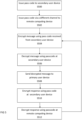
- Figure 2A is a flowchart setting out the steps for a remote computing device to connect to a faulty primary user device, e.g. a router. Once connected, tests may be performed to identify the faults and/or to perform any necessary remedial action(s).
- a first step S200 the user contacts the support centre on a secondary user device to request support.
- a secure connection is then established between a remote computing device of the support centre and the secondary user device (step S202).
- the remote computing device sends a command to the secondary user device which creates a connection between the secondary user device and the primary user device. This results in a new communication channel between the remote computing device and the primary user device via the secondary user device.
- the primary user device may send a confirmatory message which is received by the remote computing device over the new communication channel, i.e. via the secondary user device (step S206).
- the remote computing device can issue commands to the primary user device (step S208) via the secondary user device.
- the commands cause tests to run on the primary user device or change settings on the primary user device.
- the method draws to a conclusion with a determination as to whether the fault is remotely fixable (step S212). If the problem is fixable remotely, the method will terminate with the device being fixed. However, if the problem is not remotely fixable, i.e. a configuration setting to fix the problem cannot be remotely changed or the problem cannot be diagnosed, the method may conclude with a message to instruct the user to seek further assistance.
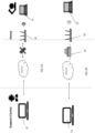
- FIG. 2B is a schematic block diagram of a system which implements the method of Figure 2A .
- the system comprises a primary user device 110 which in this example is a router (e.g. a broadband Wi-Fi router) configured to connect one or more user devices (not shown) to the internet. However, as illustrated by the broken connection 118, the primary user device 110 is not able to connect to the internet.
- the system also comprises a remote computing device 112 which is located in a support centre which the user contacts to fix the primary user device 110. By remote, it is meant that the computing device 112 is not located near to the primary user device, e.g. not local to or within the user's environment.
- the remote computing device 112 is unable to connect to the primary user device 110 via the internet to directly diagnose any faults.
- the remote computing device 112 is thus not able to obtain diagnostics from the router 110 and can also not remotely change its configuration if this is needed. In other words, the primary communication channel via the internet between the remote computing device 112 and the primary user device 110 is disabled.
- the system also comprises a secondary user device 116 in the form of a mobile device.
- a mobile device is a portable and typically handheld computing device (or electronic device - the words can be used inter changeably) such as a mobile phone, particularly a smartphone or a small computer, such as a tablet.
- the secondary user device 116 may connect to the internet via the primary user device 110 but is also configured with other connection interfaces, e.g. a phone network connection interface.
- the secondary user device 116 is paired with the remote computing device 112 to create a secure communication channel 119a between the two devices.
- the secure communication channel 119a is via a mobile phone network and the internet (at least in part).
- the secondary user device 116 is also connected to the primary user device 112 using any suitable connection e.g. a wireless link such as Wi-Fi or Bluetooth.
- a communication channel 119b is also formed between the primary and secondary user devices.
- the channels 119a, 119b form a second communication channel which allows messages and responses to be communicated between the remote computing device and the primary user device to enable the fault with the primary user device to be identified and if possible remotely fixed.
- a link is established between the remote computing device and the user's equipment even though the standard internet connection is not available.
- Figure 3A is a flowchart setting out the steps for a remote computing device to connect to a faulty primary user device, e.g. a router or a faulty additional user device which is connected to the primary user device. Both of the primary and additional user devices are located behind a fire wall. Once connected, tests may be performed to identify the faults and/or to perform any necessary remedial action(s).
- the method is similar to that of Figure 2A and thus in a first step S300, a remote computing device of the support centre receives a request for support from a user on their secondary user device. A secure connection is then established between the remote computing device and the secondary user device (step S302).
- the remote computing device sends a command (step S304) to the secondary user device which creates a connection between the secondary user device and the primary user device and hence to the additional user device which is already connected to the primary user device.
- An optional confirmatory message may be returned to the remote computing device over the new communication channel, i.e. via the secondary user device (step S306).
- the remote computing device can then issue commands to the primary user device via the secondary user device and/or commands to the additional user device via the secondary and primary user devices.
- the method concludes when it has been determined whether the fault is remotely fixable (step S312).
- FIG 3B is a schematic block diagram of a system which implements the method of Figure 3A .
- the system comprises a primary user device 120 which in this example is a router configured to connect one or more additional user devices 124 to the internet. Both of these devices 120, 124 are connected to the internet via a firewall 125.
- the system also comprises a remote computing device 122 which is located in a support centre which the user contacts to fix the primary user device 120 and/or the additional user device 124. In this arrangement, it is not possible for the remote computing device 122 to connect to the primary user device 120 via the internet to directly diagnose any faults because this route of communication is prohibited by the firewall 125.
- the system also comprises a secondary user device 126 in the form of a mobile device.
- the secondary user device 126 is configured with other connection interfaces, e.g. a phone network connection interface.
- the secondary user device 126 is paired with the remote computing device 122 to create a secure communication channel 129a between the two devices.
- the secure communication channel 129a is via the phone network and via the internet (at least in part).
- a communication channel 129b is also formed between the primary and secondary user devices and there is also a communication channel 129c between the primary user device and the additional user device.
- these communications between the user devices can be via any suitable connection e.g. a wireless link such as Wi-Fi or Bluetooth.
- a Bluetooth connection may be used by the secondary user device to connect to an additional user device such as a vehicle entertainment system and/or a vehicle management system (e.g. to diagnose a problem with the vehicle).
- the channels 129a, 129b form a second communication channel which allows messages and responses to be communicated between the remote computing device and the primary user device to enable the fault with the primary user device to be identified and if possible remotely fixed.
- the channels 129a, 129b, 129c form a second communication channel which allows messages and responses to be communicated between the remote computing device and the additional user device to enable the fault with the additional user device to be identified and if possible remotely fixed.
- the remote computing device effectively establishes a connection to the user's device from inside the user's network and thus may have unrestricted access to the devices. Issues with the network firewalls are thus bypassed even though connections from outside the network would be prevented or restricted by such firewalls. It is also noted that although unrestricted access may be achieved, the secondary user device might only allow limited access for user privacy reasons. A policy decision based on the particular scenario may be taken.
- Figure 3C is a schematic block diagram of a system which implements the method of Figure 3A .
- the system is similar to that in Figure 3B and thus comprises a primary user device 130, a secondary user device 136 and one or more additional user devices 134 in a user's environment and a remote computing device 132 in a support centre. Again there is a firewall 135 between the primary user device 130 and the internet.
- the secondary user device 136 is configured with other connection interfaces and the secondary user device 136 is paired with the remote computing device 132 to create a secure communication channel 139a between the two devices.
- a communication channel 139b is also formed between the primary and secondary user devices and there is also a communication channel 139c between the primary user device and the additional user device.
- the channels 139a, 139b form a second communication channel which allows messages and responses to be communicated between the remote computing device and the primary user device via the secondary user device.
- the channels 139a, 139b, 139c form a second communication channel which allows messages and responses to be communicated between the remote computing device and the additional user device via the secondary user device.
- the final parts of the second communication channel, namely channels 139b and 139c are behind the firewall. Accordingly, this configuration can be used by the remote computing device to gain unrestricted access to the primary user device because the final relay hop (e.g.
- channel 139b is from the secondary user device which is behind the firewall.
- FIG. 4A shows a flowchart for the method of pairing the remote computing device at the support centre with the secondary user device (i.e. the mobile device).
- the establishment of a secure second communication channel between the two devices is an advantage of the invention and allows the remote computing device to find the secondary user device.
- a pairing server receives a request for a pairing code from the secondary user device (step S400). This request may be generated by an app running on the secondary user device.
- the pairing code may be a randomly generated one time code (PTC) or other securely generated code.
- PTC one time code
- the pairing code is issued to the secondary user device at step S402.
- the pairing code is then displayed on the secondary user device, e.g. in the user interface for the app.
- the pairing code is also sent separately to the remote computing device (step S404).
- the separate channel may be via the user speaking to the agent controlling the remote computing device over the phone or via other channels, e.g. via a text message or online chat from the secondary user device.
- the secondary user device also contacts a relay server which forms at least part of the communication channel for relaying messages between the secondary user device and the remote computing device.
- the secondary user device sends the relay server the pairing code it has received (step S406). Once the pairing code is entered into the remote computing device, it is passed by the remote computing device to the relay server or another relay server which is connected to the first relay server (step S408).
- relay servers There may be two relay servers involved in passing messages between the two devices - a first relay server which is connected to the secondary user device and a second relay server which is connected to the remote computing device and the first relay server. These relay servers may initially have no knowledge of one another but use the pairing codes received from the respective devices to pair and hence connect the devices. As shown at step S410, there is a determination as to whether the pairing code received from the secondary user device matches (i.e. is identical) to the pairing code received from the remote computing device. This determination may be done in one or both of the first and second relay servers.
- Figure 4B shows a schematic block diagram of a system for implementing the pairing method of Figure 4A .
- the secondary user device 146 is connected to the pairing server 152 via a first communication channel 144, e.g. a channel which is opened by activating an app as described above.
- the first communication channel 144 is used to communicate the pairing code to the secondary user device 146 from the pairing server 152 on request.
- a second communication channel 148 is schematically shown between the secondary user device 146 and the remote computing device 142.
- the second communication channel may be verbal, or use other means to communicate the pairing code from the secondary user device 146 to the remote computing device 142.
- each of the secondary user device 146 and the remote computing device 142 are shown connected to respective relay servers 154b and 154a.
- Each relay server represents one of a plurality of intermediate systems which can chained together to pass messages from the remote computing device to the secondary user device (and hence to the primary user device(s)).
- the relays may be hosted in different locations and under different environments. For example, the relays may be hosted on the internet (i.e. in the cloud) and/or on the secondary user device.
- each of the pairing servers and the relay servers has the standard components such as a processor (i.e. microprocessor, central processing unit (CPU) or similar hardware, memory and communications modules to allow the communication.
- the memory may comprise volatile memory and/or non-volatile memory.
- the pairing server may further have a database D that is shared between the various instances, i.e. copies, of the server.
- the database may be used to track valid pairing codes and which relay server each secondary user device is connected.
- FIG 4A explains how devices are paired using a pairing code.
- an extra layer of security is shown to authenticate the remote computing device (i.e. the agent) with the secondary user device (i.e. the user).
- a one-time code termed a pass code is used for authentication and to prevent eavesdropping by a third party.
- the pass code is issued to the user of the secondary user device (step S500).
- the pass code may be randomly generated on the secondary user device and displayed to the user.
- the pass code is then issued via a different channel to the remote computing device (step S502).
- the pass code may be communicated verbally by the user to the agent operating the remote computing device, e.g. at the same time as communicating the pairing code.
- An alternative mechanism may be used but it is essential that the pass code is not communicated in the clear between the devices.
- messages and responses between the remote computing device and the secondary user device may be sent in encrypted form using the pass code or encryption derived from the pass code.
- the remote computing device encrypts a message using the pass code and sends it to the secondary user device.
- the message may be a command to run a diagnostic test or a change to the set-up on the primary user device or other user device.
- the message is decrypted using the pass code. If there is any interception of the message at the relays or other parts of the communication path, the intercepting components will not be able to decrypt the message because they do not know the pass code. Furthermore, any alternation of the message by intercepting components means that the decryption will fail at the secondary user device.
- the message is decrypted, it is sent to the primary user device (step S508) or to the other user device which may be faulty.
- a response is received and this is encrypted by the secondary user device using the pass code (step S510) before sending to the remote computing device.
- the response can be decrypted (step S512). Accordingly, end-to-end encryption is used for the communication between the two devices.
- another message can be sent and the process of steps S504 to S512 may repeat until the fault is diagnosed and if possible rectified.
- the remote computing device may be send each command message at any time and may batch command messages to send as groups of messages. Similarly, each response may be sent independently of the other responses, regardless of whether or not the command messages were batched, and the responses may be sent in any order, not just the order in which the command messages were sent.
- the mechanism used above to authenticate communication between the two devices may be a standard mechanism, e.g. secure remote password (SRP) such as that developed by Stanford University. It will be appreciated that other similar mechanisms could be used to secure the communication.
- SRP secure remote password
- Figure 6 is a variant of the system shown in Figure 4B and the same components have the same numbering.
- the secondary user device 146 is connected to the pairing server 152 via a first communication channel 144 to communicate the pairing code to the secondary user device 146.
- a second communication channel 148 between the secondary user device 146 and the remote computing device 142 is used to communicate the pairing code from the secondary user device 146 to the remote computing device 142.
- the secondary user device is shown as directly connected to its respective relay server 154b but it will be appreciated that a similar variation could also be employed in this connection.
- the remote computing device opens a normal browser and connects to the proxy server 156 which may be running on the internet.
- HTTP (or HTTPS) commands from the browser operating on the remote computing device are packaged by the proxy server 156 and sent via the relay servers to the secondary user device as described above.
- the app on the secondary user device converts the packaged commands to HTTP/HTTPS commands and sends them to the problem device (e.g. the primary user device or the additional user device). This allows the agent using the remote computing device to interact and view webpages as if they were directly connected to the problem device. Responses are transferred back to the browser of the remote computing device in the same way.
- HTTP commands are just one type of command that may be sent.
- the proxy server (or another mechanism) may also be used to package other bespoke commands, including commands in a custom protocol.
- the packaged commands will be interpreted by the secondary user device and used to construct custom commands for the problem device (e.g. the primary user device or the additional user device).
- At least some of the example embodiments described herein may be constructed, partially or wholly, using dedicated special-purpose hardware.
- Terms such as 'component', ⁇ module' or 'unit' used herein may include, but are not limited to, a hardware device, such as circuitry in the form of discrete or integrated components, a Field Programmable Gate Array (FPGA) or Application Specific Integrated Circuit (ASIC), which performs certain tasks or provides the associated functionality.
- FPGA Field Programmable Gate Array
- ASIC Application Specific Integrated Circuit
- the described elements may be configured to reside on a tangible, persistent, addressable storage medium and may be configured to execute on one or more processors.
- These functional elements may in some embodiments include, by way of example, components, such as software components, object-oriented software components, class components and task components, processes, functions, attributes, procedures, subroutines, segments of program code, drivers, firmware, microcode, circuitry, data, databases, data structures, tables, arrays, and variables.
- components such as software components, object-oriented software components, class components and task components, processes, functions, attributes, procedures, subroutines, segments of program code, drivers, firmware, microcode, circuitry, data, databases, data structures, tables, arrays, and variables.
Landscapes
- Engineering & Computer Science (AREA)
- Theoretical Computer Science (AREA)
- General Engineering & Computer Science (AREA)
- Computer Security & Cryptography (AREA)
- Computer Networks & Wireless Communication (AREA)
- Signal Processing (AREA)
- Quality & Reliability (AREA)
- Physics & Mathematics (AREA)
- General Physics & Mathematics (AREA)
- Computer Hardware Design (AREA)
- Computer And Data Communications (AREA)
Claims (15)
- Verfahren zum Verwenden einer fernen Computervorrichtung (112), um einen Fehler bei einer primären Benutzervorrichtung (110) aus der Ferne zu diagnostizieren, wobei das Verfahren umfasst:Empfangen, in der fernen Computervorrichtung (112), einer Anforderung von einer sekundären Benutzervorrichtung (116), um einen Fehler in der primären Benutzervorrichtung (110) zu diagnostizieren, wobei die Anforderung auf einem ersten Kommunikationskanal empfangen wird, wobei sich die primäre und die sekundäre Benutzervorrichtung (110, 116) innerhalb einer Benutzerumgebung befinden und wobei die ferne Computervorrichtung (112) in einem Supportzentrum untergebracht ist, das sich nicht innerhalb der Benutzerumgebung befindet;Verbinden, als Reaktion auf die Anforderung, der fernen Computervorrichtung (112) mit der sekundären Benutzervorrichtung (116) unter Verwendung eines sicheren Kommunikationskanals, der verschieden von dem ersten Kommunikationskanal ist;Senden eines Verbindungsbefehls von der fernen Computervorrichtung (112) zu der sekundären Benutzervorrichtung (116), um die primäre Benutzervorrichtung (110) unter Verwendung eines dritten Kommunikationskanals zu verbinden, der verschieden von dem sicheren Kommunikationskanal ist und dadurch eine Kommunikation über die sekundäre Computervorrichtung (116) zwischen der fernen Computervorrichtung (112) und der primären Benutzervorrichtung (110) erlaubt;Senden einer Befehlsnachricht für die primäre Benutzervorrichtung (110) von der fernen Computervorrichtung (112) über den sicheren Kommunikationskanal zu der sekundären Benutzervorrichtung (116), wobei die Befehlsnachricht ausgewählt wird aus einem Befehl zum Initiieren eines Diagnosetests und einem Befehl zum Verändern einer Konfigurationseinstellung und unter Verwendung des dritten Kommunikationskanals von der sekundären Benutzervorrichtung (116) zu der primären Benutzervorrichtung (110) gesendet wird; undEmpfangen, in der fernen Computervorrichtung (112) von der sekundären Benutzervorrichtung (116) über den sicheren Kommunikationskanal, von allen Antworten auf die Befehlsnachricht, die von der primären Benutzervorrichtung (110) ausgegeben werden;wodurch die Antwort mindestens teilweise verwendet wird, um den Fehler zu diagnostizieren.
- Verfahren nach Anspruch 1, wobei das Verbinden unter Verwendung eines sicheren Kommunikationskanals umfasst:Empfangen eines Kopplungscodes von der sekundären Benutzervorrichtung (116) über einen primären Kanal;Senden des empfangenen Kopplungscodes zu einem Kopplungsserver; undEmpfangen einer Bestätigung von dem Kopplungsserver, dass der Kopplungscode gültig ist;wobei der Kopplungsserver den Kopplungscode überprüft, der von der fernen Computervorrichtung (112) empfangen wurde, indem ermittelt wird, ob eine Übereinstimmung mit einem zweiten Kopplungscode besteht, der von der sekundären Benutzervorrichtung (116) über einen sekundären Kanal empfangen wurde.
- Verfahren nach Anspruch 1 oder Anspruch 2, das ferner umfasst:
Verschlüsseln der Befehlsnachricht unter Verwendung eines Schlüssels, der gemeinsam mit der sekundären Benutzervorrichtung (116) genutzt wird. - Verfahren nach einem der vorhergehenden Ansprüche, wobei die Befehlsnachricht ein Befehl zum Initiieren eines Diagnosetests an der primären Benutzervorrichtung (110) ist.
- Verfahren nach einem der vorhergehenden Ansprüche, das ferner umfasst:Senden, basierend auf der empfangenen Antwort, einer nachfolgenden Befehlsnachricht für die primäre Benutzervorrichtung (110) von der fernen Computervorrichtung (112) über den sicheren Kommunikationskanal zu der sekundären Benutzervorrichtung (116); undEmpfangen, von der sekundären Benutzervorrichtung (116) über den sicheren Kommunikationskanal, von allen Antworten auf die Befehlsnachricht, die von der primären Benutzervorrichtung (110) ausgegeben werden.
- Verfahren nach einem der vorhergehenden Ansprüche, wobei die Befehlsnachricht ein Befehl zum Verändern einer Konfigurationseinstellung in der primären Benutzervorrichtung (110) ist.
- Verfahren nach einem der vorhergehenden Ansprüche, das ferner umfasst:Empfangen, als Reaktion auf das Senden des Verbindungsbefehls, einer Bestätigung, dass die primäre Benutzervorrichtung (110) mit der sekundären Benutzervorrichtung (116) verbunden ist; undSenden der Befehlsnachricht, nachdem die Bestätigung empfangen wurde.
- Verfahren nach einem der vorhergehenden Ansprüche, wobei der sichere Kommunikationskanal über ein mobiles Netzwerk erfolgt.
- Verfahren nach einem der vorhergehenden Ansprüche, wobei der dritte Kommunikationskanal ein lokaler drahtloser Kommunikationskanal ist.
- Verfahren zum Verwenden einer sekundären Benutzervorrichtung, um einen Fehler bei einer primären Benutzervorrichtung (110) aus der Ferne zu diagnostizieren, wobei das Verfahren umfasst:Senden einer Anforderung, um einen Fehler bei der primären Benutzervorrichtung (110) zu diagnostizieren, von der sekundären Benutzervorrichtung (116) zu einer fernen Computervorrichtung (112), wobei die Anforderung über einen ersten Kommunikationskanal gesendet wird, wobei sich die primäre und die sekundäre Benutzervorrichtung (110, 116) innerhalb einer Benutzerumgebung befinden und wobei die ferne Computervorrichtung (112) in einem Supportzentrum untergebracht ist, das sich nicht innerhalb der Benutzerumgebung befindet;Verbinden, als Reaktion auf die Anforderung, der sekundären Benutzervorrichtung (116) mit der fernen Computervorrichtung (112) unter Verwendung eines sicheren Kommunikationskanals, der verschieden von dem ersten Kommunikationskanal ist;Verbinden der sekundären Benutzervorrichtung (116) mit der primären Benutzervorrichtung (110) unter Verwendung eines dritten Kommunikationskanals, der verschieden von dem sicheren Kommunikationskanal ist, wodurch eine Kommunikation über die sekundäre Computervorrichtung (116) zwischen der fernen Computervorrichtung (112) und der primären Benutzervorrichtung (110) erlaubt wird;Empfangen, in der sekundären Benutzervorrichtung (116), einer Befehlsnachricht für die primäre Benutzervorrichtung (110) von der fernen Computervorrichtung (112) über den sicheren Kommunikationskanal, wobei die Befehlsnachricht ausgewählt wird aus einem Befehl zum Initiieren eines Diagnosetests und einem Befehl zum Verändern einer Konfigurationseinstellung;Senden der Befehlsnachricht von der sekundären Benutzervorrichtung (116) über den dritten Kommunikationskanal zu der primären Benutzervorrichtung (110); undZurücksenden, unter Verwendung der sekundären Benutzervorrichtung (116), von allen Antworten auf die Befehlsnachricht, die von der primären Benutzervorrichtung (110) empfangen werden, über den sicheren Kommunikationskanal zu der fernen Computervorrichtung (112), wodurch die Antwort mindestens teilweise verwendet wird, um den Fehler zu diagnostizieren.
- Verfahren nach Anspruch 10, das ferner umfasst:Empfangen einer verschlüsselten Befehlsnachricht, die unter Verwendung eines Schlüssels verschlüsselt wurde, der gemeinsam mit der fernen Computervorrichtung (112) genutzt wird;Entschlüsseln der verschlüsselten Befehlsnachricht unter Verwendung des gemeinsam genutzten Schlüssels; undSenden der Befehlsnachricht zu der primären Benutzervorrichtung (110).
- Verfahren nach Anspruch 11, das ferner ein Neuverschlüsseln der Befehlsnachricht vor dem Senden zu der primären Benutzervorrichtung (110) umfasst.
- Nicht-flüchtiges computerlesbares Medium, das einen Programmcode enthält, der, wenn er von einer Computervorrichtung ausgeführt wird, die Computervorrichtung veranlasst, das Verfahren nach einem der Ansprüche 1 bis 12 auszuführen.
- Ferne Computervorrichtung (112), die konfiguriert ist zum Implementieren des Verfahrens nach einem der Ansprüche 1 bis 9.
- Sekundäre Benutzervorrichtung (116), die konfiguriert ist zum Implementieren des Verfahrens nach einem der Ansprüche 10 bis 12.
Applications Claiming Priority (2)
| Application Number | Priority Date | Filing Date | Title |
|---|---|---|---|
| GB1812398.4A GB2575697B (en) | 2018-07-30 | 2018-07-30 | Remote control system |
| PCT/GB2019/052132 WO2020025946A1 (en) | 2018-07-30 | 2019-07-30 | Remote control system |
Publications (3)
| Publication Number | Publication Date |
|---|---|
| EP3830697A1 EP3830697A1 (de) | 2021-06-09 |
| EP3830697B1 true EP3830697B1 (de) | 2024-10-23 |
| EP3830697B8 EP3830697B8 (de) | 2024-12-04 |
Family
ID=63518243
Family Applications (1)
| Application Number | Title | Priority Date | Filing Date |
|---|---|---|---|
| EP19748935.4A Active EP3830697B8 (de) | 2018-07-30 | 2019-07-30 | Fernsteuerungssystem |
Country Status (4)
| Country | Link |
|---|---|
| US (1) | US11917415B2 (de) |
| EP (1) | EP3830697B8 (de) |
| GB (1) | GB2575697B (de) |
| WO (1) | WO2020025946A1 (de) |
Families Citing this family (1)
| Publication number | Priority date | Publication date | Assignee | Title |
|---|---|---|---|---|
| WO2025207809A1 (en) * | 2024-03-28 | 2025-10-02 | Visa International Service Association | Access device interaction method using multiple user devices |
Citations (2)
| Publication number | Priority date | Publication date | Assignee | Title |
|---|---|---|---|---|
| US6260160B1 (en) * | 1998-06-15 | 2001-07-10 | Siemens Information And Communication Networks, Inc. | Remote troubleshooting of a computing device |
| WO2013151808A1 (en) * | 2012-04-05 | 2013-10-10 | Assurant, Inc. | System, method, apparatus, and computer program product for providing mobile device support services |
Family Cites Families (14)
| Publication number | Priority date | Publication date | Assignee | Title |
|---|---|---|---|---|
| US7760654B2 (en) * | 2004-09-24 | 2010-07-20 | Microsoft Corporation | Using a connected wireless computer as a conduit for a disconnected wireless computer |
| US9100300B2 (en) * | 2013-06-25 | 2015-08-04 | International Business Machines Corporation | Mitigating network connection problems using supporting devices |
| US9210646B2 (en) * | 2013-07-11 | 2015-12-08 | Verizon Patent And Licensing Inc. | Back-up path for in-home diagnostics and other communications |
| CN104579733B (zh) * | 2013-10-25 | 2018-05-11 | 华为终端有限公司 | 故障诊断的方法、设备及系统 |
| US9634857B2 (en) * | 2013-11-15 | 2017-04-25 | Avago Technologies General Ip (Singapore) Pte. Ltd. | Auxiliary channel remote device management, diagnostics, and self-installation |
| US20170289159A1 (en) * | 2016-03-31 | 2017-10-05 | Intel IP Corporation | Security support for free wi-fi and sponsored connectivity for paid wi-fi |
| EP3244645B1 (de) * | 2016-05-09 | 2021-09-15 | ABB Schweiz AG | Paarungsverfahren |
| WO2018119782A1 (en) * | 2016-12-28 | 2018-07-05 | Intel Corporation | Techniques for windowed substrate integrated circuit packages |
| WO2018119872A1 (zh) * | 2016-12-29 | 2018-07-05 | 海能达通信股份有限公司 | 通信故障检测方法、装置以及射频拉远电路 |
| WO2018160530A1 (en) * | 2017-02-28 | 2018-09-07 | Leviton Manufacturing Co., Inc. | Communication enabled circuit breakers |
| US10708668B2 (en) * | 2017-03-06 | 2020-07-07 | Sonifi Solutions, Inc. | Methods and systems for remotely monitoring connectivity and network performance in hospitality environments |
| EP3396994B1 (de) * | 2017-04-27 | 2020-12-02 | ABB Schweiz AG | Herstellen einer lokalen verbindung |
| US10608868B2 (en) * | 2017-11-29 | 2020-03-31 | International Business Machines Corporation | System and method for proactive distributed agent based network diagnosis |
| US10901830B2 (en) * | 2018-07-05 | 2021-01-26 | International Business Machines Corporation | Electronic checklist |
-
2018
- 2018-07-30 GB GB1812398.4A patent/GB2575697B/en active Active
-
2019
- 2019-07-30 EP EP19748935.4A patent/EP3830697B8/de active Active
- 2019-07-30 US US17/264,395 patent/US11917415B2/en active Active
- 2019-07-30 WO PCT/GB2019/052132 patent/WO2020025946A1/en not_active Ceased
Patent Citations (2)
| Publication number | Priority date | Publication date | Assignee | Title |
|---|---|---|---|---|
| US6260160B1 (en) * | 1998-06-15 | 2001-07-10 | Siemens Information And Communication Networks, Inc. | Remote troubleshooting of a computing device |
| WO2013151808A1 (en) * | 2012-04-05 | 2013-10-10 | Assurant, Inc. | System, method, apparatus, and computer program product for providing mobile device support services |
Also Published As
| Publication number | Publication date |
|---|---|
| GB201812398D0 (en) | 2018-09-12 |
| GB2575697B (en) | 2020-08-19 |
| EP3830697A1 (de) | 2021-06-09 |
| EP3830697B8 (de) | 2024-12-04 |
| WO2020025946A1 (en) | 2020-02-06 |
| US20210297863A1 (en) | 2021-09-23 |
| GB2575697A (en) | 2020-01-22 |
| US11917415B2 (en) | 2024-02-27 |
Similar Documents
| Publication | Publication Date | Title |
|---|---|---|
| JP7383368B2 (ja) | プロセスプラントから別のシステムへの通信を安全に転送するための方法、システム | |
| US20190317481A1 (en) | Firewall System and Method for Establishing Secured Communications Connections to an Industrial Automation System | |
| US10469268B2 (en) | Unified encryption configuration management and setup system | |
| US10356046B2 (en) | Restricting communications in industrial control | |
| JP6700688B2 (ja) | プロセス制御システムに対するデバイスの安全化 | |
| US8989386B2 (en) | Method and device for providing at least one secure cryptographic key | |
| JP4928539B2 (ja) | 安全な遠隔アクセスのための装置 | |
| JP2018098773A (ja) | セキュリティ保護されたプロセス制御通信 | |
| CN103036867A (zh) | 基于相互认证的虚拟专用网络服务设备和方法 | |
| US12199958B1 (en) | System and method for cryptologically tethering user devices to one another in adaptable manner for trusted communication across untrusted network | |
| CN101938485A (zh) | 基于双向安全认证的点对点协议的IP Camera服务实现方法 | |
| US20160112464A1 (en) | Session transfer protocol between different browsers on different devices | |
| CN103369667A (zh) | 无线通信系统 | |
| US10015208B2 (en) | Single proxies in secure communication using service function chaining | |
| EP3830697B1 (de) | Fernsteuerungssystem | |
| US20170295488A1 (en) | Method for generating a key and method for secure communication between a household appliance and an appliance | |
| JP2017059873A (ja) | 遠隔制御装置、及び制御システム | |
| CN112205018A (zh) | 监控网络中的加密连接的方法、设备和计算机程序产品 | |
| US20240251266A1 (en) | Communication monitoring system in control network | |
| JP4777693B2 (ja) | 認証システム及び端末装置及び認証装置及び認証方法 | |
| JP7392713B2 (ja) | 通信装置及び通信方法 | |
| JP6049841B1 (ja) | 車載ネットワーク管理装置及び車載ネットワーク管理方法 | |
| JP6571624B2 (ja) | 装置管理システム、管理対象装置、装置管理サーバ、制御方法、及び制御プログラム | |
| WO2012144591A1 (ja) | 中継装置 | |
| CN102761869B (zh) | 一种802.1x认证方法和设备 |
Legal Events
| Date | Code | Title | Description |
|---|---|---|---|
| STAA | Information on the status of an ep patent application or granted ep patent |
Free format text: STATUS: UNKNOWN |
|
| STAA | Information on the status of an ep patent application or granted ep patent |
Free format text: STATUS: THE INTERNATIONAL PUBLICATION HAS BEEN MADE |
|
| PUAI | Public reference made under article 153(3) epc to a published international application that has entered the european phase |
Free format text: ORIGINAL CODE: 0009012 |
|
| STAA | Information on the status of an ep patent application or granted ep patent |
Free format text: STATUS: REQUEST FOR EXAMINATION WAS MADE |
|
| 17P | Request for examination filed |
Effective date: 20210226 |
|
| AK | Designated contracting states |
Kind code of ref document: A1 Designated state(s): AL AT BE BG CH CY CZ DE DK EE ES FI FR GB GR HR HU IE IS IT LI LT LU LV MC MK MT NL NO PL PT RO RS SE SI SK SM TR |
|
| DAV | Request for validation of the european patent (deleted) | ||
| DAX | Request for extension of the european patent (deleted) | ||
| STAA | Information on the status of an ep patent application or granted ep patent |
Free format text: STATUS: EXAMINATION IS IN PROGRESS |
|
| 17Q | First examination report despatched |
Effective date: 20220707 |
|
| GRAP | Despatch of communication of intention to grant a patent |
Free format text: ORIGINAL CODE: EPIDOSNIGR1 |
|
| STAA | Information on the status of an ep patent application or granted ep patent |
Free format text: STATUS: GRANT OF PATENT IS INTENDED |
|
| INTG | Intention to grant announced |
Effective date: 20240514 |
|
| GRAS | Grant fee paid |
Free format text: ORIGINAL CODE: EPIDOSNIGR3 |
|
| GRAA | (expected) grant |
Free format text: ORIGINAL CODE: 0009210 |
|
| STAA | Information on the status of an ep patent application or granted ep patent |
Free format text: STATUS: THE PATENT HAS BEEN GRANTED |
|
| AK | Designated contracting states |
Kind code of ref document: B1 Designated state(s): AL AT BE BG CH CY CZ DE DK EE ES FI FR GB GR HR HU IE IS IT LI LT LU LV MC MK MT NL NO PL PT RO RS SE SI SK SM TR |
|
| REG | Reference to a national code |
Ref country code: GB Ref legal event code: FG4D |
|
| REG | Reference to a national code |
Ref country code: CH Ref legal event code: EP |
|
| REG | Reference to a national code |
Ref country code: DE Ref legal event code: R096 Ref document number: 602019060798 Country of ref document: DE |
|
| REG | Reference to a national code |
Ref country code: CH Ref legal event code: PK Free format text: BERICHTIGUNG B8 |
|
| REG | Reference to a national code |
Ref country code: IE Ref legal event code: FG4D |
|
| RBV | Designated contracting states (corrected) |
Designated state(s): AL AT BE BG CH CY CZ DE DK EE ES FI FR GR HR HU IE IS IT LI LT LU LV MC MK MT NL NO PL PT RO RS SE SI SK SM TR |
|
| REG | Reference to a national code |
Ref country code: LT Ref legal event code: MG9D |
|
| REG | Reference to a national code |
Ref country code: NL Ref legal event code: MP Effective date: 20241023 |
|
| REG | Reference to a national code |
Ref country code: AT Ref legal event code: MK05 Ref document number: 1735400 Country of ref document: AT Kind code of ref document: T Effective date: 20241023 |
|
| PG25 | Lapsed in a contracting state [announced via postgrant information from national office to epo] |
Ref country code: NL Free format text: LAPSE BECAUSE OF FAILURE TO SUBMIT A TRANSLATION OF THE DESCRIPTION OR TO PAY THE FEE WITHIN THE PRESCRIBED TIME-LIMIT Effective date: 20241023 |
|
| PG25 | Lapsed in a contracting state [announced via postgrant information from national office to epo] |
Ref country code: NL Free format text: LAPSE BECAUSE OF FAILURE TO SUBMIT A TRANSLATION OF THE DESCRIPTION OR TO PAY THE FEE WITHIN THE PRESCRIBED TIME-LIMIT Effective date: 20241023 |
|
| PG25 | Lapsed in a contracting state [announced via postgrant information from national office to epo] |
Ref country code: PT Free format text: LAPSE BECAUSE OF FAILURE TO SUBMIT A TRANSLATION OF THE DESCRIPTION OR TO PAY THE FEE WITHIN THE PRESCRIBED TIME-LIMIT Effective date: 20250224 Ref country code: IS Free format text: LAPSE BECAUSE OF FAILURE TO SUBMIT A TRANSLATION OF THE DESCRIPTION OR TO PAY THE FEE WITHIN THE PRESCRIBED TIME-LIMIT Effective date: 20250223 Ref country code: HR Free format text: LAPSE BECAUSE OF FAILURE TO SUBMIT A TRANSLATION OF THE DESCRIPTION OR TO PAY THE FEE WITHIN THE PRESCRIBED TIME-LIMIT Effective date: 20241023 |
|
| PG25 | Lapsed in a contracting state [announced via postgrant information from national office to epo] |
Ref country code: FI Free format text: LAPSE BECAUSE OF FAILURE TO SUBMIT A TRANSLATION OF THE DESCRIPTION OR TO PAY THE FEE WITHIN THE PRESCRIBED TIME-LIMIT Effective date: 20241023 |
|
| PG25 | Lapsed in a contracting state [announced via postgrant information from national office to epo] |
Ref country code: BG Free format text: LAPSE BECAUSE OF FAILURE TO SUBMIT A TRANSLATION OF THE DESCRIPTION OR TO PAY THE FEE WITHIN THE PRESCRIBED TIME-LIMIT Effective date: 20241023 |
|
| PG25 | Lapsed in a contracting state [announced via postgrant information from national office to epo] |
Ref country code: ES Free format text: LAPSE BECAUSE OF FAILURE TO SUBMIT A TRANSLATION OF THE DESCRIPTION OR TO PAY THE FEE WITHIN THE PRESCRIBED TIME-LIMIT Effective date: 20241023 |
|
| PG25 | Lapsed in a contracting state [announced via postgrant information from national office to epo] |
Ref country code: NO Free format text: LAPSE BECAUSE OF FAILURE TO SUBMIT A TRANSLATION OF THE DESCRIPTION OR TO PAY THE FEE WITHIN THE PRESCRIBED TIME-LIMIT Effective date: 20250123 |
|
| PG25 | Lapsed in a contracting state [announced via postgrant information from national office to epo] |
Ref country code: AT Free format text: LAPSE BECAUSE OF FAILURE TO SUBMIT A TRANSLATION OF THE DESCRIPTION OR TO PAY THE FEE WITHIN THE PRESCRIBED TIME-LIMIT Effective date: 20241023 Ref country code: GR Free format text: LAPSE BECAUSE OF FAILURE TO SUBMIT A TRANSLATION OF THE DESCRIPTION OR TO PAY THE FEE WITHIN THE PRESCRIBED TIME-LIMIT Effective date: 20250124 Ref country code: LV Free format text: LAPSE BECAUSE OF FAILURE TO SUBMIT A TRANSLATION OF THE DESCRIPTION OR TO PAY THE FEE WITHIN THE PRESCRIBED TIME-LIMIT Effective date: 20241023 |
|
| PG25 | Lapsed in a contracting state [announced via postgrant information from national office to epo] |
Ref country code: PL Free format text: LAPSE BECAUSE OF FAILURE TO SUBMIT A TRANSLATION OF THE DESCRIPTION OR TO PAY THE FEE WITHIN THE PRESCRIBED TIME-LIMIT Effective date: 20241023 |
|
| PG25 | Lapsed in a contracting state [announced via postgrant information from national office to epo] |
Ref country code: RS Free format text: LAPSE BECAUSE OF FAILURE TO SUBMIT A TRANSLATION OF THE DESCRIPTION OR TO PAY THE FEE WITHIN THE PRESCRIBED TIME-LIMIT Effective date: 20250123 |
|
| PG25 | Lapsed in a contracting state [announced via postgrant information from national office to epo] |
Ref country code: SM Free format text: LAPSE BECAUSE OF FAILURE TO SUBMIT A TRANSLATION OF THE DESCRIPTION OR TO PAY THE FEE WITHIN THE PRESCRIBED TIME-LIMIT Effective date: 20241023 |
|
| PG25 | Lapsed in a contracting state [announced via postgrant information from national office to epo] |
Ref country code: DK Free format text: LAPSE BECAUSE OF FAILURE TO SUBMIT A TRANSLATION OF THE DESCRIPTION OR TO PAY THE FEE WITHIN THE PRESCRIBED TIME-LIMIT Effective date: 20241023 |
|
| PG25 | Lapsed in a contracting state [announced via postgrant information from national office to epo] |
Ref country code: RO Free format text: LAPSE BECAUSE OF FAILURE TO SUBMIT A TRANSLATION OF THE DESCRIPTION OR TO PAY THE FEE WITHIN THE PRESCRIBED TIME-LIMIT Effective date: 20241023 |
|
| REG | Reference to a national code |
Ref country code: DE Ref legal event code: R097 Ref document number: 602019060798 Country of ref document: DE |
|
| PG25 | Lapsed in a contracting state [announced via postgrant information from national office to epo] |
Ref country code: SK Free format text: LAPSE BECAUSE OF FAILURE TO SUBMIT A TRANSLATION OF THE DESCRIPTION OR TO PAY THE FEE WITHIN THE PRESCRIBED TIME-LIMIT Effective date: 20241023 |
|
| PG25 | Lapsed in a contracting state [announced via postgrant information from national office to epo] |
Ref country code: CZ Free format text: LAPSE BECAUSE OF FAILURE TO SUBMIT A TRANSLATION OF THE DESCRIPTION OR TO PAY THE FEE WITHIN THE PRESCRIBED TIME-LIMIT Effective date: 20241023 |
|
| PG25 | Lapsed in a contracting state [announced via postgrant information from national office to epo] |
Ref country code: IT Free format text: LAPSE BECAUSE OF FAILURE TO SUBMIT A TRANSLATION OF THE DESCRIPTION OR TO PAY THE FEE WITHIN THE PRESCRIBED TIME-LIMIT Effective date: 20241023 |
|
| PLBE | No opposition filed within time limit |
Free format text: ORIGINAL CODE: 0009261 |
|
| STAA | Information on the status of an ep patent application or granted ep patent |
Free format text: STATUS: NO OPPOSITION FILED WITHIN TIME LIMIT |
|
| PG25 | Lapsed in a contracting state [announced via postgrant information from national office to epo] |
Ref country code: SE Free format text: LAPSE BECAUSE OF FAILURE TO SUBMIT A TRANSLATION OF THE DESCRIPTION OR TO PAY THE FEE WITHIN THE PRESCRIBED TIME-LIMIT Effective date: 20241023 |
|
| 26N | No opposition filed |
Effective date: 20250724 |
|
| PGFP | Annual fee paid to national office [announced via postgrant information from national office to epo] |
Ref country code: FR Payment date: 20251230 Year of fee payment: 8 |
|
| REG | Reference to a national code |
Ref country code: CH Ref legal event code: H13 Free format text: ST27 STATUS EVENT CODE: U-0-0-H10-H13 (AS PROVIDED BY THE NATIONAL OFFICE) Effective date: 20260224 |
|
| PG25 | Lapsed in a contracting state [announced via postgrant information from national office to epo] |
Ref country code: LU Free format text: LAPSE BECAUSE OF NON-PAYMENT OF DUE FEES Effective date: 20250730 |
|
| REG | Reference to a national code |
Ref country code: BE Ref legal event code: MM Effective date: 20250731 |
|
| PGFP | Annual fee paid to national office [announced via postgrant information from national office to epo] |
Ref country code: DE Payment date: 20260113 Year of fee payment: 7 |
|
| PG25 | Lapsed in a contracting state [announced via postgrant information from national office to epo] |
Ref country code: BE Free format text: LAPSE BECAUSE OF NON-PAYMENT OF DUE FEES Effective date: 20250731 |
|
| PG25 | Lapsed in a contracting state [announced via postgrant information from national office to epo] |
Ref country code: CH Free format text: LAPSE BECAUSE OF NON-PAYMENT OF DUE FEES Effective date: 20250731 |