EP3830561B1 - Method and apparatus for identifying substances using ion mobility based ion separation techniques - Google Patents
Method and apparatus for identifying substances using ion mobility based ion separation techniques Download PDFInfo
- Publication number
- EP3830561B1 EP3830561B1 EP19748919.8A EP19748919A EP3830561B1 EP 3830561 B1 EP3830561 B1 EP 3830561B1 EP 19748919 A EP19748919 A EP 19748919A EP 3830561 B1 EP3830561 B1 EP 3830561B1
- Authority
- EP
- European Patent Office
- Prior art keywords
- electrode
- ions
- voltage
- gate
- ion
- Prior art date
- Legal status (The legal status is an assumption and is not a legal conclusion. Google has not performed a legal analysis and makes no representation as to the accuracy of the status listed.)
- Active
Links
Images



Classifications
-
- G—PHYSICS
- G01—MEASURING; TESTING
- G01N—INVESTIGATING OR ANALYSING MATERIALS BY DETERMINING THEIR CHEMICAL OR PHYSICAL PROPERTIES
- G01N27/00—Investigating or analysing materials by the use of electric, electrochemical, or magnetic means
- G01N27/62—Investigating or analysing materials by the use of electric, electrochemical, or magnetic means by investigating the ionisation of gases, e.g. aerosols; by investigating electric discharges, e.g. emission of cathode
- G01N27/622—Ion mobility spectrometry
- G01N27/623—Ion mobility spectrometry combined with mass spectrometry
-
- G—PHYSICS
- G01—MEASURING; TESTING
- G01N—INVESTIGATING OR ANALYSING MATERIALS BY DETERMINING THEIR CHEMICAL OR PHYSICAL PROPERTIES
- G01N27/00—Investigating or analysing materials by the use of electric, electrochemical, or magnetic means
- G01N27/62—Investigating or analysing materials by the use of electric, electrochemical, or magnetic means by investigating the ionisation of gases, e.g. aerosols; by investigating electric discharges, e.g. emission of cathode
- G01N27/622—Ion mobility spectrometry
-
- G—PHYSICS
- G01—MEASURING; TESTING
- G01N—INVESTIGATING OR ANALYSING MATERIALS BY DETERMINING THEIR CHEMICAL OR PHYSICAL PROPERTIES
- G01N27/00—Investigating or analysing materials by the use of electric, electrochemical, or magnetic means
- G01N27/26—Investigating or analysing materials by the use of electric, electrochemical, or magnetic means by investigating electrochemical variables; by using electrolysis or electrophoresis
- G01N27/28—Electrolytic cell components
- G01N27/30—Electrodes, e.g. test electrodes; Half-cells
- G01N27/333—Ion-selective electrodes or membranes
-
- G—PHYSICS
- G01—MEASURING; TESTING
- G01N—INVESTIGATING OR ANALYSING MATERIALS BY DETERMINING THEIR CHEMICAL OR PHYSICAL PROPERTIES
- G01N27/00—Investigating or analysing materials by the use of electric, electrochemical, or magnetic means
- G01N27/26—Investigating or analysing materials by the use of electric, electrochemical, or magnetic means by investigating electrochemical variables; by using electrolysis or electrophoresis
- G01N27/403—Cells and electrode assemblies
- G01N27/4035—Combination of a single ion-sensing electrode and a single reference electrode
-
- H—ELECTRICITY
- H01—ELECTRIC ELEMENTS
- H01J—ELECTRIC DISCHARGE TUBES OR DISCHARGE LAMPS
- H01J49/00—Particle spectrometers or separator tubes
- H01J49/02—Details
- H01J49/06—Electron- or ion-optical arrangements
- H01J49/061—Ion deflecting means, e.g. ion gates
Definitions
- the present invention relates to methods and apparatus for identifying substances of interest, and more particularly to methods and apparatus for selecting and/or modifying ions to assist in the identification of a substance of interest in a sample.
- spectrometers such as ion mobility spectrometers and/or mass spectrometers.
- Ion mobility spectrometers can identify material from a sample of interest by ionizing the material (e.g., molecules, atoms) and measuring the time it takes the resulting ions to travel a known distance under a known electric field. This is known as time of flight ion mobility spectrometry - TOFIMS.
- the time of flight of packets of ions can be measured by a detector. This time of flight is associated with the ion's mobility.
- An ion's mobility relates to its mass and geometry. Therefore, by measuring the time of flight of an ion in the detector it is possible to infer an identity for the ion. These times of flight may be displayed graphically or numerically as a plasmagram.
- ions are selected based on the dependency of the ion mobility on electric field strength. To do this, ions may be subjected to varying electric field strengths selected so that only ions having a selected differential mobility are able to pass though the spectrometer.
- ions are separated by the application of a high-voltage asymmetric waveform at radio frequency (RF) combined with a DC voltage.
- RF radio frequency
- the electric field varies, depending on the ratio of the high-field and low-field mobility of an ion, it will migrate toward one or the other electrode. Only ions with specific differential mobility will pass through the device.
- Mass spectrometry works by ionizing chemical compounds to generate charged molecules or molecule fragments and measuring their mass-to-charge ratios.
- ions are separated according to their mass-to-charge ratio, typically by accelerating them and measuring the degree to which they are deflected by an applied electric or magnetic field.
- Some mass spectrometers operate using ion traps.
- Mass spectra reflect the relative abundance of detected ions as a function of their mass-to-charge ratio.
- the ions can be identified by comparing known masses to the identified masses or by comparing obtained spectra to known spectra. Ions of the same mass-to-charge ratio will undergo the same amount of deflection, but a single mass-charge ratio may be associated with a number of different species of ions.
- a spectrometer To improve the ability of a spectrometer to identify ions in a sample of interest, it is suggested to modify some of the ions using a radio frequency, RF, electric field (e.g. by fragmenting them) to provide additional information which can be used to infer an identity for the ions.
- This provides additional degrees of freedom in the measurement of the ions, and therefore may improve the ability to resolve differences between ions.
- WO2012/098364 describes a detection device including an ionisation region, an ion gate comprising two electrodes, an ion modifier, a drift chamber and a collector.
- the methods and apparatus of the present disclosure find application in ion mobility spectrometry and in mass spectrometry systems employing ion mobility based ion separation techniques.
- Figure 1 shows a cut away view of an ion mobility spectrometer, 100.
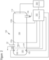
- Figure 2 shows a schematic diagram of the same IMS 100 to assist in understanding the layout illustrated in Figure 1 .
- the ion gate of the IMS 100 shown in Figure 1 is used both to prevent ions from leaving the reaction region 103, and to perform ion modification.
- the ion gate comprises a first electrode 106-1 and a second electrode 106-2, which may be spaced apart from the first electrode 106-1 in the drift direction of the ion mobility spectrometer (e.g. in the direction of the longitudinal axis of the IMS cell).
- a voltage difference is applied between the first electrode 106-1 and the second electrode 106-2 to prevent ions from leaving the reaction region 103.
- the DC voltage on the first electrode 106-1 and the second electrode 106-2 is controlled to match the voltage profile of the ion mobility spectrometer 100.
- an RF voltage is applied between the first electrode 106-1 and the second electrode 106-2 to fragment ions as they pass through the gate 106.
- the IMS illustrated there may include an ioniser 102 and a reaction region 103 that is separated from a drift region 104 by a gate 106.
- the gate 106 comprises a first electrode 106-1 and a second electrode 106-2.
- the IMS 100 includes an inlet 108 (not visible in Figure 2 ) for enabling material from a sample to be introduced to the reaction region 103 where it can be ionised by reactant ions generated by the the ioniser 102.
- the inlet 108 may comprise a pinhole or membrane inlet, for obtaining a sample of gaseous fluid such as a vapour or gas.
- the ioniser 102 may comprise a source of ions such as a corona discharge element or a radioactive source.
- the drift region 104 lies between the gate 106 and a collector 118.
- a series of drift electrodes 120a, 120b are spaced apart along the drift region 104 for providing a voltage profile for moving ions from the reaction region to the collector 118.
- the voltage profile applied by the drift electrodes 120a, 120b may comprise a uniform electric field (e.g. spatially uniform voltage gradient) in the drift direction from the ioniser 102 along the drift region 104 toward the collector 118.
- the collector 118 may be coupled to provide a signal to a controller 200. Current flow from the collector 118 can be used by the controller 200 to infer that ions have reached the collector 118, and a characteristic of the ions can be determined based on the time for ions to pass from the gate 106 along the drift region 104 to the collector 118. Examples of a collector 118 are configured to provide a signal indicating that ions have arrived at the collector 118.
- the collector may comprise a conductive electrode (such as a faraday plate), which may be charged to catch ions.
- drift gas inlet 90 may be arranged for providing a flow of drift gas into the drift chamber.
- a drift gas outlet 92 may be provided at the end of the drift region 104 adjacent the gate 106, so that drift gas can flow from the collector 118 to the gate 106.
- ions can travel from the gate 106 to the collector 118 along the voltage profile and against the flow of drift gas to enable their time of flight through the drift gas to be used to infer information about their mobility.
- Example drift gases include, but are not limited to, nitrogen, helium, air, air that is recirculated (e.g., air that is cleaned and/or dried) and so forth.
- Each of the two gate electrodes 106-1, 106-2 can comprise an array of elongate conductors, such as wires, which may be arranged across the IMS cell - e.g. transverse to the drift direction from the reaction region to the detector.
- the elongate conductors may be arranged in a grid, such as a mesh.
- the conductors of each ion modifier electrode 106-1, 106-2 may have gaps between them such that ions can pass through each electrode by travelling through the gaps.
- the first electrode 106-1 may be provided adjacent the reaction region, and may separate the second electrode 106-2 from the reaction region.
- the elongate conductors of the first electrode 106-1 may be parallel with each other, and may be arranged in a single planar array, which may span the IMS cell (e.g. the elongate conductors of the first electrode 106-1 may be coplanar with each other).
- the elongate conductors of the second electrode 106-2 may also be parallel with each other, and may be arranged in a single planar array, which may span the IMS cell (e.g. the elongate conductors of the second electrode 106-2 may be coplanar with each other).
- the first electrode 106-1 and the second electrode 106-2 may be non-coplanar with each other. For example they may be spaced apart from each other in the drift direction of the IMS cell. Typically, this spacing between the first electrode 106-1 and the second electrode 106-2 may be at least 200 micron.
- the elongate conductors of the first of the electrodes 106-1 may be parallel with those of the second electrode 106-2.
- the elongate conductors of the first electrode 106-1 may be laterally aligned with those of the second. For example they may be aligned with each other in a direction transverse (e.g. perpendicular) to the drift direction. Thus, when viewed along the drift direction (e.g.
- the elongate conductors of the second electrode 106-2 may be entirely hidden by those of the first 106-1.
- the two electrodes 106-1, 106-2 may be structurally identical and laterally aligned. This may help to reduce ion losses due to collision, and may also enhance sensitivity by preventing the voltage of the second electrode from distorting electric field upstream of the first.
- a voltage provider 202 is connected to the ion gate 106, and to the drift electrodes 120a, 120b. It may also be connected to the ioniser.
- the voltage provider may comprise circuitry, such as a power supply and/or a series potential divider, configured to apply the voltage profile via the drift electrodes 120a, 120b in the drift region 104. It also comprises circuitry for providing a selected DC voltage at each of the two gate electrodes 106-1, 106-2 of the ion gate 106. And, it also comprises circuitry such as a generator of radio frequency, RF, signals for providing an RF, alternating voltage between those two same electrodes 106-1, 106-2.
- a controller 200 may be connected to the voltage provider 202 for controlling these voltages and may also be connected to the collector 118 for receiving signals indicating the arrival of ions at the collector 118.
- the controller 200 can thus operate the gate 106 to control passage of ions from the reaction region into the drift region 104.
- To prevent ions from travelling from the reaction region into the drift region it may operate the voltage provider to apply a voltage between the two electrodes 106-1, 106-2 to create a barrier to ions.
- This voltage may provide an electric field which opposes the electric field due to the voltage profile.
- the voltage of the second electrode 106-2 of the ion gate 106 may be controlled to match the profile voltage at the location of the second electrode 106-2, while a different voltage can be applied to the first electrode 106-1 of the ion gate to provide an electric field which opposes the electric field due to the voltage profile.
- the controller 200 may operate the voltage provider 202 so that the DC voltage between the two electrodes of the ion gate matches the profile voltage.
- a DC voltage can be applied to the first electrode 106-1 so that its voltage matches (e.g. is equal to) the profile voltage at its location. This can enable ions to pass through gaps between the conductors of the first electrode 106-1, into a region 129 (illustrated more clearly in Figure 2 ) between the electrodes 106-1, 106-2. They may then travel out of the region 129 through the gaps between the conductors of the electrode 106-2 and continue to travel in the drift direction (e.g. down the voltage profile) towards the collector 118.
- the controller 200 may operate the voltage provider 202 to apply an RF voltage between the first electrode 106-1 and the second electrode 106-2 while holding the gate open (e.g. controlling the DC voltage of the two electrodes 106-1, 106-2 to match the profile voltage).
- the RF voltage may be superimposed on the DC voltage difference between the two electrodes 106-1, 106-2.
- the controller 200 and the voltage provider 202 may be configured to close the gate by returning the first electrode 106-1 of the ion gate 106 to its previous DC voltage (e.g. different from the profile voltage to create a barrier to the passage of ions). They may also be configured to switch off the RF voltage between the gate electrodes 106-1, 106-2 when the gate is closed.
- a sample of gaseous fluid (e.g. a gas or vapour) may be provided 300 from the inlet to the ioniser.
- the ioniser is then operated 302 to generate reactant ions which can be mixed with the sample in the reaction region to ionise the sample.
- a DC voltage different from the profile voltage, is applied 304 between the first electrode 106-1 and the second electrode of the ion gate 106-2. This DC voltage difference opposes the voltage profile and thus prevents ions from leaving the reaction region 103 and travelling along the drift region 104.
- the ion gate 106 can then be opened 306 to allow ions to travel from the reaction region down the drift region to the collector.
- the gate is held open in this way for a selected period (referred to as the gate width) to enable a packet of ions to travel through the gate.
- the gate is then closed 308.
- This time period determines the width of the packet of ions, and so also provides a fundamental limit on the time resolution of the IMS cell - typically gate widths of about 200 microseconds are used.
- the packet of ions then travels along the drift chamber (down the voltage profile) against the flow of drift gas, and may spread out in the drift direction as they travel towards the collector 118 - more mobile ions moving more quickly. Thus time of flight of the ions indicates their mobility through the drift gas.
- the controller can receive signals from the collector indicting the arrival of the ions at the collector, and by comparing the timing of these signals with the timing of the gate opening, the time of flight of ions in the packet can be determined 310. This time of flight can in turn be used to infer information about the mobility of the ions, and thus to identify them.
- peaks in a plasmagram may have a certain width, and may be masked or overlap with other peaks.
- certain ions may bond with ions and/or molecules in the reaction region.
- the controller may perform a repeat experiment - e.g. to repeat the measurement of time of flight on a second packet of ions.
- the controller may determine 312 whether the time of flight data provide an ambiguity as to the identity of the ions. If not, the sample may be identified 314 based on the time of flight data.
- the ion gate 106 can be opened 316 a second time to allow a further packet of ions to leave the reaction region.
- This further packet of ions may be generated by a further operation of the sample inlet 108 and ioniser 102 as described above.
- this further packet of ions thus travels from the reaction region into a region 129 between the first electrode 106-1 and the second electrode 106-2.
- An RF voltage is then applied 318 between the first electrode 106-1 and the second electrode 106-2. This may raise the effective temperature of the ions with the aim of fragmenting them to provide daughter ions.
- the RF voltage applied between the electrodes is at least 2.5MHz, and is of the order of 10 4 Vcm -1 .
- the RF voltage may be about 8MHz and about 40,000 Vcm -1 .
- the gate can be closed 320 by reapplying the barrier voltage.
- the RF voltage may also be switched off.
- the daughter ions can then travel down the drift region, along the voltage profile through the drift gas towards the collector.
- the time of flight of the daughter ions from the ion gate to the collector can then be determined 322.
- the controller can then use the time of flight of the daughter ions, and the time of flight of the preceding packet of ions to try to identify 314 the ions.
- the preceding cycle of operation in which the IMS cell 100 is operated without applying the RF voltage to the gate electrodes 106-1, 106-2, is optional.
- the RF voltage can be applied without a preceding cycle in which it is not applied.
- the drift time between the ion gate and the collector may be increased as compared to systems in which the ion modifier is deployed at some intermediate position along the drift chamber.
- Electrodes 120a, 120b may be arranged to guide ions toward the collector 118, for example the drift electrodes 120a, 120b may comprise rings which may be arranged around the drift region 104 to focus ions onto the detector 118.
- the example of Figure 1 includes only two drift electrodes 120a, 120b, in some examples a plurality of electrodes may be used, or a single electrode may be used in combination with the detector 118 to apply an electric field to guide ions toward the detector 118.
- first electrode and the second electrode are described as being spaced apart in the drift direction, but it will be appreciated in the context of the present disclosure that co planar ion gates may be used.
- Figure 4 shows a diagram of an ion mobility based ion separator for an inlet of a mass spectrometer.
- the controller may select a subset of a sample of ions based on their mobility in the drift gas by controlling the relative timing of opening the first ion gate and the second ion gate.
- the timing of opening the second ion gate may be selected based on the timing of opening the first ion gate to allow only those ions having a particular time of flight along the drift chamber (and/or a selected range or ranges of times of flight) to pass to the outlet.
- the outlet may comprise a capillary or other conduit adapted for connection to an inlet of a mass spectrometer.
- Ion focussing apparatus such as an ion guide may be arranged to direct ions along this narrow passage.
- the second ion gate 106 is disposed between the drift region and the outlet of the separator to provide a controllable barrier therebetween.
- the two electrodes 106-1, 106-2 of the second ion gate 106 are spaced apart in a drift direction of the ion mobility separator.
- the ion mobility based ion separator of Figure 4 thus comprises a source of ions such as a pinhole or membrane inlet, for obtaining a sample of gaseous fluid such as a vapour or gas, and an ioniser for ionising the sample.
- the ioniser may comprise a source of ions such as a corona discharge element or a radioactive source.
- the sample may be ionised using an ionised reactant gas.
- the controller operates the inlet to draw a sample into the reaction region, and operates the ioniser to ionise the sample - typically by generating reactant ions for mixing with the sample in the reaction region.
- the first ion gate is then opened to allow a packet of ions to travel along the drift region toward the second ion gate. It will be appreciated in the context of the present disclosure that this packet of ions may separate longitudinally as it travels along the drift chamber due to differences in mobility of the ions in the packet.
- the second ion gate 106 may be held closed by applying a barrier voltage between the two electrodes 106-1, 106-2 of the second ion gate. This can cause ions arriving at the second ion gate to be neutralised on the first electrode 106-1, and thus prevented from reaching the outlet and leaving the separator via the outlet.
- the barrier voltage comprises a voltage which matches the voltage profile at the first electrode 106-1. This may assist in reducing disturbance of the voltage profile in the drift region.
- the second ion gate 106 can then be opened (e.g. by making the voltage of the second electrode 106-2 also match the voltage profile to allow ions arriving at the first electrode 106-1 to travel onwards towards the outlet. Whilst the second ion gate 106 is open, the ions can travel into a modification region between the two electrodes of the second ion gate.
- an RF voltage is applied between the two electrodes to fragment ions as they pass through the region.
- the gate can then be closed again to neutralise further ions (e.g. those arriving after the selected portion of ions) and prevent them from reaching the outlet.
- opening the second ion gate may comprise applying a DC voltage difference between the two electrodes of the second ion gate.
- This DC voltage difference may match the voltage profile, so that the electric field along the drift region to the outlet may be uniform when the second gate is open.
- the RF voltage applied between the two electrodes 106-1, 106-2, to fragment the ions may be superimposed on the DC voltage difference between them.
- the RF voltage between the two electrodes 106-1, 106-2 may have a frequency of at least 2.5 MHz.
- the frequency is at least 3 MHz, or at least 5 MHz, in some embodiments at least 6 MHz.
- the frequency is less than 100 MHz, in some embodiments the frequency is less than 50 MHz, in some embodiments less than 20 MHz, in some embodiments less than 15 MHz, or less than 10 MHz.
- the frequency may be between 3 MHz and 20 MHz, or between 6 MHz and 12MHz. In some examples the frequency is about 8 MHz.
- the voltage provider may control the voltage of the two gate electrodes 106-1, 106-2 to vary, during the gate width, with a selected phase difference, for example the voltage controller may control the voltage of the two gate electrodes 106-1, 106-2 so that the positive voltage excursion of one electrode occurs during the negative voltage excursion of the other.
- the voltage provider may control the voltage of the two gate electrodes 106-1, 106-2 to vary in anti-phase.
- the voltage excursions of the two electrodes may be of the same amplitude.
- the functionality of the controller may be provided by a general purpose processor, which may be configured to perform a method according to any one of those described herein.
- the controller may comprise digital logic, such as field programmable gate arrays, FPGA, application specific integrated circuits, ASIC, a digital signal processor, DSP, or by any other appropriate hardware.
- one or more memory elements can store data and/or program instructions used to implement the operations described herein.
- Embodiments of the disclosure provide tangible, non-transitory storage media comprising program instructions operable to program a processor to perform any one or more of the methods described and/or claimed herein and/or to provide data processing apparatus as described and/or claimed herein in combination with the spectrometer according to claim 9.
- the controller may comprise an analogue control circuit which provides at least a part of this control functionality.
- An embodiment provides an analogue control circuit configured to perform any one or more of the methods described herein in combination with the spectrometer according to claim 9.
Landscapes
- Chemical & Material Sciences (AREA)
- Physics & Mathematics (AREA)
- Health & Medical Sciences (AREA)
- Life Sciences & Earth Sciences (AREA)
- Analytical Chemistry (AREA)
- Chemical Kinetics & Catalysis (AREA)
- Electrochemistry (AREA)
- Biochemistry (AREA)
- General Health & Medical Sciences (AREA)
- General Physics & Mathematics (AREA)
- Immunology (AREA)
- Pathology (AREA)
- Spectroscopy & Molecular Physics (AREA)
- Molecular Biology (AREA)
- Other Investigation Or Analysis Of Materials By Electrical Means (AREA)
Priority Applications (1)
| Application Number | Priority Date | Filing Date | Title |
|---|---|---|---|
| EP23195136.9A EP4286840A3 (en) | 2018-07-31 | 2019-07-26 | Method and apparatus for identifying substances using ion mobility based ion separation techniques |
Applications Claiming Priority (2)
| Application Number | Priority Date | Filing Date | Title |
|---|---|---|---|
| GB1812481.8A GB2576003B (en) | 2018-07-31 | 2018-07-31 | Ion gate configured to fragment ions in ion mobility spectrometry |
| PCT/GB2019/052102 WO2020025933A1 (en) | 2018-07-31 | 2019-07-26 | Method and apparatus for identifying substances using ion mobility based ion separation techniques |
Related Child Applications (1)
| Application Number | Title | Priority Date | Filing Date |
|---|---|---|---|
| EP23195136.9A Division EP4286840A3 (en) | 2018-07-31 | 2019-07-26 | Method and apparatus for identifying substances using ion mobility based ion separation techniques |
Publications (3)
| Publication Number | Publication Date |
|---|---|
| EP3830561A1 EP3830561A1 (en) | 2021-06-09 |
| EP3830561B1 true EP3830561B1 (en) | 2023-09-06 |
| EP3830561C0 EP3830561C0 (en) | 2023-09-06 |
Family
ID=63518220
Family Applications (2)
| Application Number | Title | Priority Date | Filing Date |
|---|---|---|---|
| EP19748919.8A Active EP3830561B1 (en) | 2018-07-31 | 2019-07-26 | Method and apparatus for identifying substances using ion mobility based ion separation techniques |
| EP23195136.9A Pending EP4286840A3 (en) | 2018-07-31 | 2019-07-26 | Method and apparatus for identifying substances using ion mobility based ion separation techniques |
Family Applications After (1)
| Application Number | Title | Priority Date | Filing Date |
|---|---|---|---|
| EP23195136.9A Pending EP4286840A3 (en) | 2018-07-31 | 2019-07-26 | Method and apparatus for identifying substances using ion mobility based ion separation techniques |
Country Status (10)
| Country | Link |
|---|---|
| US (1) | US11994491B2 (pl) |
| EP (2) | EP3830561B1 (pl) |
| JP (1) | JP7416760B2 (pl) |
| KR (2) | KR20250010150A (pl) |
| CN (1) | CN112601957A (pl) |
| CA (1) | CA3108208A1 (pl) |
| GB (1) | GB2576003B (pl) |
| MX (1) | MX2021001253A (pl) |
| PL (1) | PL3830561T3 (pl) |
| WO (1) | WO2020025933A1 (pl) |
Families Citing this family (2)
| Publication number | Priority date | Publication date | Assignee | Title |
|---|---|---|---|---|
| CN115079299A (zh) * | 2022-05-06 | 2022-09-20 | 北京中泰通达科技发展有限公司 | 基于便携式检测仪的危险物品检测方法及装置 |
| GB2631677B (en) * | 2023-04-25 | 2026-02-18 | Smiths Detection Watford Ltd | Method and apparatus |
Family Cites Families (24)
| Publication number | Priority date | Publication date | Assignee | Title |
|---|---|---|---|---|
| US6323482B1 (en) * | 1997-06-02 | 2001-11-27 | Advanced Research And Technology Institute, Inc. | Ion mobility and mass spectrometer |
| US6960761B2 (en) * | 1997-06-02 | 2005-11-01 | Advanced Research & Technology Institute | Instrument for separating ions in time as functions of preselected ion mobility and ion mass |
| US6498342B1 (en) * | 1997-06-02 | 2002-12-24 | Advanced Research & Technology Institute | Ion separation instrument |
| GB2339958B (en) * | 1998-07-17 | 2001-02-21 | Genomic Solutions Ltd | Time-of-flight mass spectrometer |
| US6744043B2 (en) | 2000-12-08 | 2004-06-01 | Mds Inc. | Ion mobilty spectrometer incorporating an ion guide in combination with an MS device |
| RU2187099C1 (ru) | 2001-05-30 | 2002-08-10 | ООО "Лаборатория биохимических методов" | Устройство для измерения спектров подвижности ионов |
| JP3971958B2 (ja) * | 2002-05-28 | 2007-09-05 | 株式会社日立ハイテクノロジーズ | 質量分析装置 |
| GB2403063A (en) * | 2003-06-21 | 2004-12-22 | Anatoli Nicolai Verentchikov | Time of flight mass spectrometer employing a plurality of lenses focussing an ion beam in shift direction |
| JP4231775B2 (ja) * | 2003-12-24 | 2009-03-04 | 株式会社日立ハイテクノロジーズ | イオントラップ/飛行時間型質量分析計 |
| US7064322B2 (en) * | 2004-10-01 | 2006-06-20 | Agilent Technologies, Inc. | Mass spectrometer multipole device |
| GB0426900D0 (en) * | 2004-12-08 | 2005-01-12 | Micromass Ltd | Mass spectrometer |
| RU2293977C2 (ru) | 2005-02-21 | 2007-02-20 | Владимир Иванович Капустин | Спектрометр ионной подвижности |
| GB0508239D0 (en) | 2005-04-23 | 2005-06-01 | Smiths Group Plc | Detection apparatus |
| GB0624740D0 (en) * | 2006-12-12 | 2007-01-17 | Micromass Ltd | Mass spectrometer |
| CN101688848A (zh) | 2007-02-05 | 2010-03-31 | 卓漂仪谱公司 | 离子迁移谱仪与方法 |
| GB0704137D0 (en) * | 2007-03-03 | 2007-04-11 | Smiths Detection Watford Ltd | Ion mobility spectrometers |
| GB201021360D0 (en) | 2010-12-16 | 2011-01-26 | Thermo Fisher Scient Bremen Gmbh | Apparatus and methods for ion mobility spectrometry |
| GB201101132D0 (en) | 2011-01-21 | 2011-03-09 | Smiths Detection Watford Ltd | Combination ion gate and modifier |
| US9541524B2 (en) | 2012-02-16 | 2017-01-10 | Smiths Detection-Watford Limited | Synchronized ion modification |
| GB2517670B (en) * | 2013-03-15 | 2020-04-29 | Smiths Detection Watford Ltd | Ion modification |
| GB201417185D0 (en) * | 2014-09-29 | 2014-11-12 | Smiths Detection Watford Ltd | Apparatus and methods |
| GB2531292B (en) * | 2014-10-14 | 2019-06-12 | Smiths Detection Watford Ltd | Method and apparatus |
| GB2531285B (en) | 2014-10-14 | 2017-07-26 | Smiths Detection-Watford Ltd | Ion mobility spectrometer with ion modification |
| GB201513472D0 (en) * | 2015-07-30 | 2015-09-16 | Smiths Detection Watford Ltd | Apparatus and method |
-
2018
- 2018-07-31 GB GB1812481.8A patent/GB2576003B/en active Active
-
2019
- 2019-07-26 CN CN201980051317.9A patent/CN112601957A/zh active Pending
- 2019-07-26 JP JP2021505377A patent/JP7416760B2/ja active Active
- 2019-07-26 EP EP19748919.8A patent/EP3830561B1/en active Active
- 2019-07-26 CA CA3108208A patent/CA3108208A1/en active Pending
- 2019-07-26 PL PL19748919.8T patent/PL3830561T3/pl unknown
- 2019-07-26 KR KR1020257001372A patent/KR20250010150A/ko active Pending
- 2019-07-26 MX MX2021001253A patent/MX2021001253A/es unknown
- 2019-07-26 US US17/264,504 patent/US11994491B2/en active Active
- 2019-07-26 WO PCT/GB2019/052102 patent/WO2020025933A1/en not_active Ceased
- 2019-07-26 KR KR1020217005581A patent/KR102757246B1/ko active Active
- 2019-07-26 EP EP23195136.9A patent/EP4286840A3/en active Pending
Also Published As
| Publication number | Publication date |
|---|---|
| WO2020025933A1 (en) | 2020-02-06 |
| EP4286840A2 (en) | 2023-12-06 |
| KR102757246B1 (ko) | 2025-01-21 |
| JP2021533353A (ja) | 2021-12-02 |
| GB2576003B (en) | 2021-02-03 |
| KR20210036951A (ko) | 2021-04-05 |
| GB201812481D0 (en) | 2018-09-12 |
| US20210293753A1 (en) | 2021-09-23 |
| KR20250010150A (ko) | 2025-01-20 |
| PL3830561T3 (pl) | 2024-02-05 |
| CA3108208A1 (en) | 2020-02-06 |
| EP4286840A3 (en) | 2024-02-28 |
| CN112601957A (zh) | 2021-04-02 |
| JP7416760B2 (ja) | 2024-01-17 |
| GB2576003A (en) | 2020-02-05 |
| MX2021001253A (es) | 2021-04-12 |
| EP3830561C0 (en) | 2023-09-06 |
| US11994491B2 (en) | 2024-05-28 |
| EP3830561A1 (en) | 2021-06-09 |
Similar Documents
| Publication | Publication Date | Title |
|---|---|---|
| US9404889B2 (en) | Method and device for detection and identification of gases | |
| US11215582B2 (en) | Method and apparatus for an ion filter of a mass spectrometer | |
| US10018593B2 (en) | Duel mode ion mobility spectrometer | |
| US11994491B2 (en) | Method and apparatus for identifying substances using ion mobility based ion separation techniques | |
| CN103460330B (zh) | 离子门和离子改变器的结合 | |
| US12510510B2 (en) | Method and apparatus for separating ions | |
| RU2795499C2 (ru) | Способ и устройство для идентификации веществ с использованием способа разделения ионов на основе ионной подвижности | |
| GB2631677A (en) | Method and apparatus | |
| GB2569059B (en) | Method and apparatus |
Legal Events
| Date | Code | Title | Description |
|---|---|---|---|
| STAA | Information on the status of an ep patent application or granted ep patent |
Free format text: STATUS: UNKNOWN |
|
| STAA | Information on the status of an ep patent application or granted ep patent |
Free format text: STATUS: THE INTERNATIONAL PUBLICATION HAS BEEN MADE |
|
| PUAI | Public reference made under article 153(3) epc to a published international application that has entered the european phase |
Free format text: ORIGINAL CODE: 0009012 |
|
| STAA | Information on the status of an ep patent application or granted ep patent |
Free format text: STATUS: REQUEST FOR EXAMINATION WAS MADE |
|
| 17P | Request for examination filed |
Effective date: 20210129 |
|
| AK | Designated contracting states |
Kind code of ref document: A1 Designated state(s): AL AT BE BG CH CY CZ DE DK EE ES FI FR GB GR HR HU IE IS IT LI LT LU LV MC MK MT NL NO PL PT RO RS SE SI SK SM TR |
|
| DAV | Request for validation of the european patent (deleted) | ||
| DAX | Request for extension of the european patent (deleted) | ||
| REG | Reference to a national code |
Ref country code: DE Ref legal event code: R079 Free format text: PREVIOUS MAIN CLASS: G01N0027620000 Ipc: G01N0027623000 Ref country code: DE Ref legal event code: R079 Ref document number: 602019036828 Country of ref document: DE Free format text: PREVIOUS MAIN CLASS: G01N0027620000 Ipc: G01N0027623000 |
|
| GRAP | Despatch of communication of intention to grant a patent |
Free format text: ORIGINAL CODE: EPIDOSNIGR1 |
|
| RIC1 | Information provided on ipc code assigned before grant |
Ipc: G01N 27/623 20210101AFI20230208BHEP |
|
| STAA | Information on the status of an ep patent application or granted ep patent |
Free format text: STATUS: GRANT OF PATENT IS INTENDED |
|
| INTG | Intention to grant announced |
Effective date: 20230316 |
|
| GRAS | Grant fee paid |
Free format text: ORIGINAL CODE: EPIDOSNIGR3 |
|
| GRAA | (expected) grant |
Free format text: ORIGINAL CODE: 0009210 |
|
| STAA | Information on the status of an ep patent application or granted ep patent |
Free format text: STATUS: THE PATENT HAS BEEN GRANTED |
|
| AK | Designated contracting states |
Kind code of ref document: B1 Designated state(s): AL AT BE BG CH CY CZ DE DK EE ES FI FR GB GR HR HU IE IS IT LI LT LU LV MC MK MT NL NO PL PT RO RS SE SI SK SM TR |
|
| REG | Reference to a national code |
Ref country code: GB Ref legal event code: FG4D |
|
| REG | Reference to a national code |
Ref country code: CH Ref legal event code: EP |
|
| REG | Reference to a national code |
Ref country code: IE Ref legal event code: FG4D |
|
| REG | Reference to a national code |
Ref country code: DE Ref legal event code: R096 Ref document number: 602019036828 Country of ref document: DE |
|
| U01 | Request for unitary effect filed |
Effective date: 20231003 |
|
| U07 | Unitary effect registered |
Designated state(s): AT BE BG DE DK EE FI FR IT LT LU LV MT NL PT SE SI Effective date: 20231012 |
|
| PG25 | Lapsed in a contracting state [announced via postgrant information from national office to epo] |
Ref country code: GR Free format text: LAPSE BECAUSE OF FAILURE TO SUBMIT A TRANSLATION OF THE DESCRIPTION OR TO PAY THE FEE WITHIN THE PRESCRIBED TIME-LIMIT Effective date: 20231207 |
|
| PG25 | Lapsed in a contracting state [announced via postgrant information from national office to epo] |
Ref country code: RS Free format text: LAPSE BECAUSE OF FAILURE TO SUBMIT A TRANSLATION OF THE DESCRIPTION OR TO PAY THE FEE WITHIN THE PRESCRIBED TIME-LIMIT Effective date: 20230906 Ref country code: NO Free format text: LAPSE BECAUSE OF FAILURE TO SUBMIT A TRANSLATION OF THE DESCRIPTION OR TO PAY THE FEE WITHIN THE PRESCRIBED TIME-LIMIT Effective date: 20231206 Ref country code: HR Free format text: LAPSE BECAUSE OF FAILURE TO SUBMIT A TRANSLATION OF THE DESCRIPTION OR TO PAY THE FEE WITHIN THE PRESCRIBED TIME-LIMIT Effective date: 20230906 Ref country code: GR Free format text: LAPSE BECAUSE OF FAILURE TO SUBMIT A TRANSLATION OF THE DESCRIPTION OR TO PAY THE FEE WITHIN THE PRESCRIBED TIME-LIMIT Effective date: 20231207 |
|
| PG25 | Lapsed in a contracting state [announced via postgrant information from national office to epo] |
Ref country code: IS Free format text: LAPSE BECAUSE OF FAILURE TO SUBMIT A TRANSLATION OF THE DESCRIPTION OR TO PAY THE FEE WITHIN THE PRESCRIBED TIME-LIMIT Effective date: 20240106 |
|
| PG25 | Lapsed in a contracting state [announced via postgrant information from national office to epo] |
Ref country code: ES Free format text: LAPSE BECAUSE OF FAILURE TO SUBMIT A TRANSLATION OF THE DESCRIPTION OR TO PAY THE FEE WITHIN THE PRESCRIBED TIME-LIMIT Effective date: 20230906 |
|
| PG25 | Lapsed in a contracting state [announced via postgrant information from national office to epo] |
Ref country code: SM Free format text: LAPSE BECAUSE OF FAILURE TO SUBMIT A TRANSLATION OF THE DESCRIPTION OR TO PAY THE FEE WITHIN THE PRESCRIBED TIME-LIMIT Effective date: 20230906 Ref country code: RO Free format text: LAPSE BECAUSE OF FAILURE TO SUBMIT A TRANSLATION OF THE DESCRIPTION OR TO PAY THE FEE WITHIN THE PRESCRIBED TIME-LIMIT Effective date: 20230906 Ref country code: IS Free format text: LAPSE BECAUSE OF FAILURE TO SUBMIT A TRANSLATION OF THE DESCRIPTION OR TO PAY THE FEE WITHIN THE PRESCRIBED TIME-LIMIT Effective date: 20240106 Ref country code: ES Free format text: LAPSE BECAUSE OF FAILURE TO SUBMIT A TRANSLATION OF THE DESCRIPTION OR TO PAY THE FEE WITHIN THE PRESCRIBED TIME-LIMIT Effective date: 20230906 Ref country code: CZ Free format text: LAPSE BECAUSE OF FAILURE TO SUBMIT A TRANSLATION OF THE DESCRIPTION OR TO PAY THE FEE WITHIN THE PRESCRIBED TIME-LIMIT Effective date: 20230906 Ref country code: SK Free format text: LAPSE BECAUSE OF FAILURE TO SUBMIT A TRANSLATION OF THE DESCRIPTION OR TO PAY THE FEE WITHIN THE PRESCRIBED TIME-LIMIT Effective date: 20230906 |
|
| REG | Reference to a national code |
Ref country code: DE Ref legal event code: R097 Ref document number: 602019036828 Country of ref document: DE |
|
| U20 | Renewal fee for the european patent with unitary effect paid |
Year of fee payment: 6 Effective date: 20240605 |
|
| PLBE | No opposition filed within time limit |
Free format text: ORIGINAL CODE: 0009261 |
|
| STAA | Information on the status of an ep patent application or granted ep patent |
Free format text: STATUS: NO OPPOSITION FILED WITHIN TIME LIMIT |
|
| 26N | No opposition filed |
Effective date: 20240607 |
|
| PG25 | Lapsed in a contracting state [announced via postgrant information from national office to epo] |
Ref country code: MC Free format text: LAPSE BECAUSE OF FAILURE TO SUBMIT A TRANSLATION OF THE DESCRIPTION OR TO PAY THE FEE WITHIN THE PRESCRIBED TIME-LIMIT Effective date: 20230906 |
|
| REG | Reference to a national code |
Ref country code: CH Ref legal event code: PL |
|
| PG25 | Lapsed in a contracting state [announced via postgrant information from national office to epo] |
Ref country code: CH Free format text: LAPSE BECAUSE OF NON-PAYMENT OF DUE FEES Effective date: 20240731 |
|
| PGFP | Annual fee paid to national office [announced via postgrant information from national office to epo] |
Ref country code: PL Payment date: 20250617 Year of fee payment: 7 |
|
| PGFP | Annual fee paid to national office [announced via postgrant information from national office to epo] |
Ref country code: GB Payment date: 20250605 Year of fee payment: 7 |
|
| U20 | Renewal fee for the european patent with unitary effect paid |
Year of fee payment: 7 Effective date: 20250606 |
|
| PG25 | Lapsed in a contracting state [announced via postgrant information from national office to epo] |
Ref country code: IE Free format text: LAPSE BECAUSE OF NON-PAYMENT OF DUE FEES Effective date: 20240726 |
|
| PG25 | Lapsed in a contracting state [announced via postgrant information from national office to epo] |
Ref country code: CY Free format text: LAPSE BECAUSE OF FAILURE TO SUBMIT A TRANSLATION OF THE DESCRIPTION OR TO PAY THE FEE WITHIN THE PRESCRIBED TIME-LIMIT; INVALID AB INITIO Effective date: 20190726 |
|
| PG25 | Lapsed in a contracting state [announced via postgrant information from national office to epo] |
Ref country code: HU Free format text: LAPSE BECAUSE OF FAILURE TO SUBMIT A TRANSLATION OF THE DESCRIPTION OR TO PAY THE FEE WITHIN THE PRESCRIBED TIME-LIMIT; INVALID AB INITIO Effective date: 20190726 |