EP3830459B1 - Method for monitoring the shut-off valve of a gas meter and gas meter thereof - Google Patents
Method for monitoring the shut-off valve of a gas meter and gas meter thereof Download PDFInfo
- Publication number
- EP3830459B1 EP3830459B1 EP19765561.6A EP19765561A EP3830459B1 EP 3830459 B1 EP3830459 B1 EP 3830459B1 EP 19765561 A EP19765561 A EP 19765561A EP 3830459 B1 EP3830459 B1 EP 3830459B1
- Authority
- EP
- European Patent Office
- Prior art keywords
- valve
- shut
- state
- switching
- actuator
- Prior art date
- Legal status (The legal status is an assumption and is not a legal conclusion. Google has not performed a legal analysis and makes no representation as to the accuracy of the status listed.)
- Active
Links
Images

Classifications
-
- F—MECHANICAL ENGINEERING; LIGHTING; HEATING; WEAPONS; BLASTING
- F16—ENGINEERING ELEMENTS AND UNITS; GENERAL MEASURES FOR PRODUCING AND MAINTAINING EFFECTIVE FUNCTIONING OF MACHINES OR INSTALLATIONS; THERMAL INSULATION IN GENERAL
- F16K—VALVES; TAPS; COCKS; ACTUATING-FLOATS; DEVICES FOR VENTING OR AERATING
- F16K37/00—Special means in or on valves or other cut-off apparatus for indicating or recording operation thereof, or for enabling an alarm to be given
- F16K37/0025—Electrical or magnetic means
- F16K37/0041—Electrical or magnetic means for measuring valve parameters
-
- F—MECHANICAL ENGINEERING; LIGHTING; HEATING; WEAPONS; BLASTING
- F16—ENGINEERING ELEMENTS AND UNITS; GENERAL MEASURES FOR PRODUCING AND MAINTAINING EFFECTIVE FUNCTIONING OF MACHINES OR INSTALLATIONS; THERMAL INSULATION IN GENERAL
- F16K—VALVES; TAPS; COCKS; ACTUATING-FLOATS; DEVICES FOR VENTING OR AERATING
- F16K31/00—Actuating devices; Operating means; Releasing devices
- F16K31/02—Actuating devices; Operating means; Releasing devices electric; magnetic
- F16K31/04—Actuating devices; Operating means; Releasing devices electric; magnetic using a motor
- F16K31/041—Actuating devices; Operating means; Releasing devices electric; magnetic using a motor for rotating valves
- F16K31/042—Actuating devices; Operating means; Releasing devices electric; magnetic using a motor for rotating valves with electric means, e.g. for controlling the motor or a clutch between the valve and the motor
-
- F—MECHANICAL ENGINEERING; LIGHTING; HEATING; WEAPONS; BLASTING
- F16—ENGINEERING ELEMENTS AND UNITS; GENERAL MEASURES FOR PRODUCING AND MAINTAINING EFFECTIVE FUNCTIONING OF MACHINES OR INSTALLATIONS; THERMAL INSULATION IN GENERAL
- F16K—VALVES; TAPS; COCKS; ACTUATING-FLOATS; DEVICES FOR VENTING OR AERATING
- F16K31/00—Actuating devices; Operating means; Releasing devices
- F16K31/44—Mechanical actuating means
- F16K31/46—Mechanical actuating means for remote operation
-
- G—PHYSICS
- G01—MEASURING; TESTING
- G01F—MEASURING VOLUME, VOLUME FLOW, MASS FLOW OR LIQUID LEVEL; METERING BY VOLUME
- G01F15/00—Details of, or accessories for, apparatus of groups G01F1/00 - G01F13/00 insofar as such details or appliances are not adapted to particular types of such apparatus
- G01F15/001—Means for regulating or setting the meter for a predetermined quantity
- G01F15/002—Means for regulating or setting the meter for a predetermined quantity for gases
-
- G—PHYSICS
- G01—MEASURING; TESTING
- G01F—MEASURING VOLUME, VOLUME FLOW, MASS FLOW OR LIQUID LEVEL; METERING BY VOLUME
- G01F15/00—Details of, or accessories for, apparatus of groups G01F1/00 - G01F13/00 insofar as such details or appliances are not adapted to particular types of such apparatus
- G01F15/005—Valves
Definitions
- the present invention relates to the field of fluid meters.
- the invention relates to a method for monitoring a shut-off valve of a gas meter and a gas meter adapted to implement such method.
- gas meters are used for measuring the amount of gas supplied to a user.
- known meters comprise an inlet conduit for the connection to the gas distribution network, and an outlet conduit for the connection to the user.
- a shut-off valve is arranged inside the meter, typically in line with the inlet conduit, capable of selectively blocking the flow of gas to the meter and, thus, supplying gas to the user placed downstream of the meter.
- shut-off valve for example, with a ball shutter, arranging opportune electric switches, which are activated by the movement of the shutter of the valve itself.
- a first switch is activated.
- a second switch is activated.
- the activation of each switch is detected by a control unit of the gas meter, which is thus able to identify the state of the shut-off valve.
- the mechanical parts of the switches are subject to corrosion - for example, galvanic corrosion and/or oxidation- and wear, so that, in time, it may not be possible to detect the state of the shut-off valve correctly.
- each switch requires a respective wiring, generally two-wire wiring, for the operation thereof. Consequently, the design, production and assembly of the shut-off valve and, more generally, of the entire gas meter, are complicated by the presence of such wiring.
- the gas meter comprises a hollow body, an inlet conduit and an outlet conduit in fluid communication with a measuring compartment of the hollow body.
- An actuator is coupled to a shut-off valve to switch it between an open state, in which it allows the flow of gas into the measuring compartment and a closed state, in which it blocks the flow of gas into the measuring compartment.
- the electric absorption of the actuator is monitored and the switching from one state to the other of the shut-off valve is determined, based on the detection of a change, above a threshold, in the electric absorption of the actuator.
- the method comprises measuring an operating temperature of the shut-off valve and, based on the temperature measured, determining a minimum acceptable time and a maximum acceptable time for the switching of the valve from one state to the other.
- the method comprises the step of counting a time elapsed from the start of a switching from one state to the other, and checking if the time elapsed is comprised between the minimum acceptable time and the maximum acceptable time.
- the method for detecting the state of the shut-off valve further comprises the step of counting a time elapsed, from the start of a switching of the shut-off valve, and checking if the time elapsed is less than a minimum acceptable time.
- the method for detecting the state of the shut-off valve further comprises the step of counting a time elapsed from a start of a switching of the shut-off valve, and checking if the time elapsed is greater than a maximum acceptable time.
- the method also comprises communicating the current state of the shut-off valve to a remote device.
- a safety procedure is carried out, if the time elapsed is not comprised between the minimum acceptable time and the maximum acceptable time.
- the safety procedure can invert the switching of the shut-off valve and bring the valve back to the previous state. Additionally or alternatively, the safety procedure can execute an alarm signal, for example, through the user interface of the control system.
- the monitoring of the electric absorption of the actuator comprises monitoring the intensity of electric current absorbed by the actuator to detect a change in the intensity of electric current absorbed.
- a different aspect of the present invention is aimed at a gas meter comprising a hollow body, which defines a measuring compartment, an inlet conduit and an outlet conduit in fluid communication with the measuring compartment.
- An actuator is coupled to a shut-off valve, preferably, it is coupled to the inlet conduit, to switch it between an open state, in which it allows the flow of gas into the measuring compartment and a closed state, in which it blocks the flow of gas into the measuring compartment.
- the gas meter comprises a control system configured to detect the state of the valve, monitoring the electric absorption of the actuator, and determining the switching of the shut-off valve from one state to the other, based on the detection of a change in the electric absorption of the actuator, above a threshold.
- the control system is configured to count a time elapsed, from a start of a switching of the shut-off valve, and check if the elapsed time is comprised between a minimum switching time and a maximum switching time.
- the minimum acceptable time and the maximum acceptable time are determined by the control system, based on the temperature measured by a temperature sensor adapted to measure an operating temperature of the shut-off valve.
- the gas meter is simple and cheap to produce.
- the shut-off valve is a ball valve.
- This type of valve is particularly adapted for the purpose of selectively blocking the flow of gas into the measuring compartment in the meter.
- the gas meter 1 comprises a hollow, box-like body 10, which delimits a measuring compartment 11 therein.
- An inlet conduit 13 and an outlet conduit 15 are made in the hollow body 10, putting the measuring compartment 11 in fluid communication with the environment external to the gas meter.
- a shut-off device 20 is coupled to the inlet conduit 13, to selectively block a flow of gas into the measuring compartment 11.
- the shut-off device 20 comprises a shut-off valve 21, for example, a ball valve, which is adapted to selectively block the fluid communication between the inlet conduit 13 and the measuring compartment 11, and an actuator 23 operatively connected to the shut-off valve 21, to switch it between a closed state, in which it blocks the flow of gas into the measuring compartment 11, and an open state, in which it allows the flow of gas into the measuring compartment 11.
- a shut-off valve 21 for example, a ball valve, which is adapted to selectively block the fluid communication between the inlet conduit 13 and the measuring compartment 11, and an actuator 23 operatively connected to the shut-off valve 21, to switch it between a closed state, in which it blocks the flow of gas into the measuring compartment 11, and an open state, in which it allows the flow of gas into the measuring compartment 11.
- a measuring apparatus 30 is coupled to the outlet conduit 15, for measuring the flow of gas crossing the measuring compartment 11.
- the gas meter 1 comprises a temperature sensor 35 housed inside the measuring compartment 11.
- the temperature sensor 35 is comprised in the measuring device 30, provided to measure an operating temperature T L of the gas 1 meter and, thus, of the shut-off valve 21.
- the gas meter 1 also comprises an electronic control system 40, for example, enclosed in a casing, which is coupled to a side wall of the hollow body 10, on a surface of the same, exposed to the external environment - i.e., opposite the measuring compartment 11.
- an electronic control system 40 for example, enclosed in a casing, which is coupled to a side wall of the hollow body 10, on a surface of the same, exposed to the external environment - i.e., opposite the measuring compartment 11.
- the control system 40 comprises a processor module 41 such as a microcontroller, a microprocessor, an ASIC, an FPGA, which is configured to control the operation of the gas meter 1, as described below, and a memory module 43, adapted to memorise instructions and/or operational data.
- a processor module 41 such as a microcontroller, a microprocessor, an ASIC, an FPGA, which is configured to control the operation of the gas meter 1, as described below
- a memory module 43 adapted to memorise instructions and/or operational data.
- control system 40 comprises a telecommunications module 45, configured to exchange information with a remote device (not shown) - for example, an information system managed by a gas distributor - by means of a wired connection and/or in radio frequency.
- a remote device not shown
- the control system further comprises a supply module 47, adapted to supply electricity to the components of the control system 40, to the shut-off device 20 and to the measuring apparatus 30.
- control system 40 is provided with a user interface 49 equipped with input devices - for example, one or more buttons - and output devices - for example, a screen, one or more LEDs, a buzzer, etc. exposed on the casing to allow information to be supplied to an operator and receive instructions from the same.
- input devices - for example, one or more buttons - and output devices - for example, a screen, one or more LEDs, a buzzer, etc. exposed on the casing to allow information to be supplied to an operator and receive instructions from the same.
- control system 40 can further comprise one or more ancillary circuits, such as a circuit for generating a synchrony signal (clock), amplifiers for input/output signals, batteries, etc., not shown in the figures.
- ancillary circuits such as a circuit for generating a synchrony signal (clock), amplifiers for input/output signals, batteries, etc., not shown in the figures.
- the control system 40 is operatively coupled to the shut-off device 20 and to the measuring apparatus 30 to control them and supply them.
- the control system 40 is operatively connected to the actuator 23 of the shut-off device 20 so as to command the actuation thereof and thus control the opening and closing of the shut-off valve 21.
- the control system 40 is also operatively connected to the temperature sensor 35 for receiving indications of an operating temperature T L of the shut-off device 20.
- the control system 40 is coupled to the actuator 23 and to the temperature sensor 35 by means of a convenient wiring.
- control system 40 is configured to monitor the state of the shut-off valve 21 of the shut-off device 20 according to instructions supplied through the telecommunications module 45 by the aforesaid remote device (not shown) - for example, the information system managed by a gas distributor.
- control system 40 is configured to supply electricity to the shut-off device 20, in particular to the actuator 23.
- the control system 40 controls the switching of the shut-off 21 from one state to the other.
- the supply module 47 of the control system 40 is configured to supply the actuator 23 with an electric current and voltage having a first polarity for switching the shut-off valve 21 from the open state to the closed state, while the supply module 47 supplies the actuator 23 with a voltage and a current having opposite polarity to the first, to switch the shut-off valve 21 in an opposite direction, i.e. from the closed state to the open state.
- the control system 40 is adapted to supply an electric current IA(t) to the actuator 23 to switch the shut-off valve 21 from one state to the other.
- the electric current IA(t) supplied to the actuator 23 is initially supplied with a switching intensity Ic - absorbed during the switching of the shut-off valve 21 from one state to the other (graph line in the interval to ⁇ t ⁇ ts).
- the switching intensity Ic is lower than the stop intensity Is because a resistant torque, to which the actuator 23 is subjected, has a lower value when the shut-off valve 21 is in communication and a higher value when it is the same blocked in the open or closed state.
- the shutter (not shown) of the shut-off valve 21 is in abutment against a corresponding stop element (not shown) and the supply of the actuator 23 can be interrupted.
- Such switching time depends on the type and structural characteristics (such as shutter dimensions, seat and body) of the shut-off valve 21 used, as well as the type and structural characteristics (such as the driving torque developed) of the actuator, and on the environmental conditions in which the shut-off valve has to operate.
- the switching time tc depends on the operating temperature T L of the shut-off device 20 - in particular, of the shut-off valve 21.
- T L the operating temperature
- the rubber of the seals - influences the physical properties of the materials - in particular, the rubber of the seals - and, consequently, the internal frictions between the components of the valve, such as, for example the existing frictions between the shutter and seals of the shut-off valve 21.
- the switching time tc is of about 5 seconds when the operating temperature T L corresponds to a standard ambient temperature of 35° C.
- the switching time tc increases to 8 seconds or more. This increase in the switching time tc is caused, for example, by the hardening of the sealing gaskets of the shut-off valve 21 due to the low associated operating temperature T L .
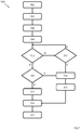
- the control system 40 is configured to implement a method 500, shown in Figure 3 , which allows the monitoring of the state of the shut-off valve 21.
- the method comprises monitoring the electric absorption - for example, the absorption of electricity, electric power or electric current - of the actuator 23 so as to identify the switchings of the shut-off valve 21 between the open state and the closed state and vice versa.
- the method 500 is implemented automatically by the control system 40.
- the processor module 41 is configured to operate according to instructions memorised in the memory module 43, for example, after receiving a switching command supplied by the remote device through the telecommunications module 45.
- the method 500 comprises measuring (block 501) the operating temperature T L of the shut-off valve 21.
- the control system 40 is configured to acquire a measurement of the operating temperature T L from the sensor 35 continuously or periodically.
- a corresponding pair of times t min and t MAX is selected (block 503), indicating a minimum acceptable switching time, denoted below as minimum time t min , and a maximum acceptable switching time, denoted below as maximum time t MAX respectively, within which a completion is expected of the switching of the shut-off valve 21, from one state to the other.
- the switching time tc is thus comprised between the minimum time t min and the maximum time t MAX .
- the maximum time t MAX is preferably, but not necessarily, greater than the switching time tc.
- the memory module 43 stores respective values of the minimum time instant t min and of the maximum time instant t MAX for different values of the operating temperature T L .
- the control system 40 selects respective values of the minimum t min and maximum t MAX times, depending on the operating temperature value T L received by the temperature sensor. If the operating temperature T L measured by the sensor 35 doesn't correspond to one of the operating temperature values T L memorised in the memory module 43, the control system 40 will select the values of the minimum times t min and maximum times t MAX associated with the operating temperature value T L memorised closest to the temperature value measured by the sensor 35.
- an intensity of the electric current supplied to the actuator 23 to switch the shut-off valve 21 is also selected (block 506), based on the measured operating temperature T L .
- the control system 40 is configured to select the intensity of the electric current IA(t) supplied by the supply module 43 and absorbed by the actuator 23 of the shut-off device 20.
- the control system 40 selects the switching current intensity Ic - to be supplied to the actuator 23 during the switching of the shut-off valve 21 from one state to the other, based on the operating temperature T L measured.
- the memory module 43 memorises two or more switching current intensities Ic - each associated with a respective operating temperature T L .
- the operating temperature T L influences the friction coefficients among components (such as shutter, seals and seat of the shutter) of the shut-off valve 21; therefore, due to the adaptation of the electricity supplied to the actuator 23 based on the operating temperature T L - in particular, due to the adaptation of the switching intensity Ic of the electric current IA(t) - it is possible to obtain a reliable switching of the shut-off valve 21.
- the method 500 further comprises counting (block 509) the time elapsed ts from the start of a switching of the shut-off valve 21 - i.e., from an initial time instant to.
- the control system 40 periodically increases a meter - for example, memorised in the memory module 43 - starting from the initial time instant to, in which it commands the switching of the shut-off valve 21, for example, supplying the actuator 23 of the shut-off device 20 with electric current and voltage of opportune polarity, as described above.
- the electric absorption of the shut-off device 20, in particular, the electric absorption of the actuator 23 is monitored (decision block 512) during the switching, with the aim of detecting changes in the same above a threshold value.
- the control system 40 is configured to monitor the trend of the electric current IA(t) absorbed by the actuator 23 of the shut-off device 20 so as to detect a change in the intensity thereof above a threshold intensity Ith and identify the stopping of the shutter of the shut-off valve.
- the threshold intensity Ith can be comprised between the switching intensity Ic and the stopping intensity Is, preferably comprised in an interval of values, which goes from an intermediate value between the switching intensity Ic and the stopping intensity Is and the stopping intensity Is itself (i.e., Ic+(Is-Ic)/2 ⁇ I th ⁇ Is).
- control system 40 verifies (block 515) whether the time elapsed ts is greater than the maximum switching time instant t MAX .
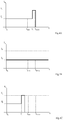
- a fault of the shut-off valve 21 is identified (block 518), because the comprised change in electric absorption is not detected (condition illustrated in the graph in Figure 4B ).
- the fault may be due to a breakage of one or more mechanical parts of the shut-off valve 21, preventing the same from stopping in the desired state.
- the implementation of a safety procedure (block 521) can be comprised.
- the safety procedure can comprise inverting the switching of the shut-off valve 21 in an attempt to return to the previous state and/or emitting an alarm signal by means of the user interface 49.
- the current state of the shut-off valve 21, in this case the fault is memorised (block 524) in the memory module 43 and communicated (block 527) to the remote device through the telecommunications module 45.
- a check is made of whether the time elapsed ts is less than the minimum time t min associated with the measured operating time T L .
- the operation moves to the block 518, identifying a fault of the shut-off valve 21.
- the change in the electric absorption of the actuator 23 occurred before the minimum time t min (t S ⁇ t min , condition illustrated in the graph in Figure 4C ) and can indicate a breakage of a component of the shut-off valve 21, which blocks the movement thereof on reaching a limit switch, or the presence of a foreign body in the same, preventing the complete switching of the shut-off valve 21.
- the operation moves to the block 521, in which the safety procedure is implemented, and then, to the blocks 524 and 527 to memorise and communicate the fault respectively, as described below.
- the steps implemented at the decision blocks 512, 530 and 533 determine a correct switching of the shut-off valve 21, checking that the change in electric absorption occurs between the minimum and maximum times t min and t MAX (t min ⁇ t S ⁇ t MAX , condition illustrated in the graph in Figure 4A )
- the operation moves to the block 524 - mentioned previously - to memorise the current state of the valve, in this case one from among the open state or the closed state, in the memory module 43.
- the control system 40 can memorise, in the memory module 43, a state information, indicative of the current state of the shut-off valve 21.
- the state information can comprise two logic states to indicate the current state of the valve 21 or a fault.
- the operation moves to the block 527 - mentioned previously - to communicate the completed switching of the shut-off valve 21 and, if necessary, the state (open or closed) currently assumed by the same, to the remote device through the telecommunications module 45 of the control system.
- the control system 40 is configured to transmit, to the remote device, a signal comprising the state information through the telecommunications module 45.
- the step of measuring the operating temperature T L can be omitted. Consequently, the alternative method will always use the same values for the minimum and maximum times t min and t MAX .
- pairs of different minimum and maximum times t min and t MAX can be defined, with specific pairs for the switching from the open state to the closed state and other specific pairs for the inverse switching, i.e. from the closed state to the open state.
- the control system is configured to select the minimum and maximum times t min and t MAX depending on the state information kept in the memory module 43. In other words, first, the current state of the shut-off valve 21 is identified and then the pair of minimum and maximum times t min and t MAX is selected to switch the shut-off valve 21 from the current state to the opposite state.
- the measuring of the operating time T L can only be implemented to adjust the minimum and maximum times t min and t MAX without modifying the switching current intensities.
- the method can comprise simply identifying the completed switching after detecting a change in the electric absorption of the actuator regardless of the duration of the switching itself.
- a number of switchings carried out by the valve can be counted. Furthermore, the open or closed state can be determined on the basis of the number of switchings counted knowing the initial state.
- the method can comprise memorising one or more, for example, all, of the switchings carried out and, if necessary, the corresponding elapsed time ts and/or the operating temperature T L measured. Alternatively, one or more pieces of such information can only be memorised in the event of a fault.
- the relative time elapsed ts and/or the measured operating temperature T L are also communicated to the remote device, together with the current state or the fault.
- shut-off valve could be a butterfly- or a gate-type valve instead of a ball valve.
- the operating temperature T L can be measured by means of a temperature sensor positioned in a different part of the gas meter 1, for example, inside the inlet conduit 13, inside the measuring compartment 11, on one of the walls of the hollow body 10 or in the shut-off device 20, for example, close to, or integrated in the shut-off valve 21.
- the gas meter 1 can comprise more than one of a temperature sensor, each having a respective positioning, and obtain the operating temperature T L by combining the measurements provided by such temperature sensors.
- any materials and contingent dimensions and shapes can be used according to the specific implementation needs without thereby departing from the protective scope of the following claims.
- the embodiment considered refers to a gas meter
- the principles of the present invention can be adapted to a meter for any fluid, also a non aeriform fluid, mutatis mutandis.
Landscapes
- Engineering & Computer Science (AREA)
- General Engineering & Computer Science (AREA)
- Mechanical Engineering (AREA)
- Physics & Mathematics (AREA)
- Fluid Mechanics (AREA)
- General Physics & Mathematics (AREA)
- Measuring Volume Flow (AREA)
- Sampling And Sample Adjustment (AREA)
Description
- The present invention relates to the field of fluid meters. In particular, the invention relates to a method for monitoring a shut-off valve of a gas meter and a gas meter adapted to implement such method.
- As is known, gas meters are used for measuring the amount of gas supplied to a user.
- Thus, known meters comprise an inlet conduit for the connection to the gas distribution network, and an outlet conduit for the connection to the user.
- A shut-off valve is arranged inside the meter, typically in line with the inlet conduit, capable of selectively blocking the flow of gas to the meter and, thus, supplying gas to the user placed downstream of the meter.
- Therefore, it is essential to know the state of the shut-off valve to control the gas supply correctly.
- To this end, it is known to check the state of the shut-off valve, for example, with a ball shutter, arranging opportune electric switches, which are activated by the movement of the shutter of the valve itself. When the valve shutter is in the first position, corresponding to an open state of the shut-off valve, a first switch is activated. When the shutter is in the second position, corresponding to a closed state of the valve, a second switch is activated. The activation of each switch is detected by a control unit of the gas meter, which is thus able to identify the state of the shut-off valve.
- However, the mechanical parts of the switches are subject to corrosion - for example, galvanic corrosion and/or oxidation- and wear, so that, in time, it may not be possible to detect the state of the shut-off valve correctly.
- Additionally, each switch requires a respective wiring, generally two-wire wiring, for the operation thereof. Consequently, the design, production and assembly of the shut-off valve and, more generally, of the entire gas meter, are complicated by the presence of such wiring.
- Solutions are known from patent applications
US2016/369898 andUS2014/343734 , wherein the state of a shut-off valve of a gas meter is monitored, by monitoring the electric absorption of an actuator, which, when coupled to the valve, switches it from an open state to a closed state. - It is an object of the present invention to overcome the drawbacks of the prior art.
- In particular, it is an object of the present invention to provide a method for identifying the state of a shut-off valve in a gas meter, which is simple and effective.
- It is also an object of the present invention to provide a gas meter, which is simple to produce and allows the state of the shut-off valve to be detected reliably for many years.
- These and other objects of the present invention are achieved by means of a device incorporating the features of the appended claims, which constitute an integral part of the present description.
- According to one aspect of the present invention, the gas meter comprises a hollow body, an inlet conduit and an outlet conduit in fluid communication with a measuring compartment of the hollow body. An actuator is coupled to a shut-off valve to switch it between an open state, in which it allows the flow of gas into the measuring compartment and a closed state, in which it blocks the flow of gas into the measuring compartment. To detect the state of the valve, the electric absorption of the actuator is monitored and the switching from one state to the other of the shut-off valve is determined, based on the detection of a change, above a threshold, in the electric absorption of the actuator. The method comprises measuring an operating temperature of the shut-off valve and, based on the temperature measured, determining a minimum acceptable time and a maximum acceptable time for the switching of the valve from one state to the other. Thus, the method comprises the step of counting a time elapsed from the start of a switching from one state to the other, and checking if the time elapsed is comprised between the minimum acceptable time and the maximum acceptable time.
- In this way, it is possible to consider the normal changes in operation of the valve due to the operating conditions of the gas meter and check that the shut-off valve has reached the desired state in a simple and reliable manner and without requiring sensors comprising mechanical parts, which are movable or exposed to the gas and, thus to the risk of corrosion.
- In one embodiment, the method for detecting the state of the shut-off valve further comprises the step of counting a time elapsed, from the start of a switching of the shut-off valve, and checking if the time elapsed is less than a minimum acceptable time.
- Thanks to such solution, it is possible to identify some types of faults, in particular a possible obstruction of the shut-off valve.
- In one embodiment, the method for detecting the state of the shut-off valve further comprises the step of counting a time elapsed from a start of a switching of the shut-off valve, and checking if the time elapsed is greater than a maximum acceptable time.
- Thanks to such solution, it is possible to identify other types of faults, in particular, it is possible to identify if a valve is idling.
- In one embodiment, the method also comprises communicating the current state of the shut-off valve to a remote device.
- Thanks to this solution, it is possible to update a remote device, such as an IT network of a gas distributor, in good time, on the state of the gas meter and, in particular, signal faults of the shut-off valve in good time.
- In one embodiment, a safety procedure is carried out, if the time elapsed is not comprised between the minimum acceptable time and the maximum acceptable time. The safety procedure can invert the switching of the shut-off valve and bring the valve back to the previous state. Additionally or alternatively, the safety procedure can execute an alarm signal, for example, through the user interface of the control system.
- Thanks to this solution, it is possible to mitigate the negative effects of the fault and/or call the attention of a user or a technician in the event of a fault.
- In one embodiment, the monitoring of the electric absorption of the actuator comprises monitoring the intensity of electric current absorbed by the actuator to detect a change in the intensity of electric current absorbed.
- In this way, the identification of the changes in the electric absorption of the actuator - and, thus, of the switchings of the stop valve - are implemented in a particularly efficient manner.
- A different aspect of the present invention is aimed at a gas meter comprising a hollow body, which defines a measuring compartment, an inlet conduit and an outlet conduit in fluid communication with the measuring compartment. An actuator is coupled to a shut-off valve, preferably, it is coupled to the inlet conduit, to switch it between an open state, in which it allows the flow of gas into the measuring compartment and a closed state, in which it blocks the flow of gas into the measuring compartment. Furthermore, the gas meter comprises a control system configured to detect the state of the valve, monitoring the electric absorption of the actuator, and determining the switching of the shut-off valve from one state to the other, based on the detection of a change in the electric absorption of the actuator, above a threshold. The control system is configured to count a time elapsed, from a start of a switching of the shut-off valve, and check if the elapsed time is comprised between a minimum switching time and a maximum switching time. The minimum acceptable time and the maximum acceptable time are determined by the control system, based on the temperature measured by a temperature sensor adapted to measure an operating temperature of the shut-off valve.
- Thanks to such solution, it is possible to know the state of the shut-off valve with precision, without implementing specific mechanical or electromechanical components, thus, the gas meter is simple and cheap to produce. In particular, it is possible to monitor the temperature of the shut-off valve during the operation of the same and compensate the normal changes in operation of the valve due to the operating conditions of the gas meter.
- In one embodiment, the shut-off valve is a ball valve.
- This type of valve is particularly adapted for the purpose of selectively blocking the flow of gas into the measuring compartment in the meter.
- Further features and objects of the present invention will become clearer from the following description.
- The invention will be described below with reference to various examples, provided for non-limiting, explanatory purposes, and illustrated in the attached drawings. These drawings illustrate different aspects and embodiments of the present invention and, where appropriate, reference numerals illustrating structures, components, materials and/or similar elements in different figures are indicated with similar reference numerals.
-
Figure 1 is a schematic representation of a gas meter according to one embodiment of the present invention; -
Figure 2 is a block diagram of the gas meter inFigure 1 ; -
Figure 3 is a flow diagram of a method for controlling a flow of gas in a gas meter according to one embodiment of the present invention, and -
Figures 4A, 4B and 4C are graphs of the trend of the current absorbed by an actuator of a shut-off device of the gas meter inFigures 1 and 2 . - While the invention is susceptible to various modifications and alternative constructions, certain preferred embodiments are shown in the drawings and are described in detail below. Nonetheless, it must be understood that there is no intention to limit the invention to the specific embodiment illustrated, but, on the contrary, the invention intends to cover all modifications and alternative and equivalent constructions that lie within the scope of the invention, as defined in the claims.
- The use of "for example", "etc.", "or" indicates non-exclusive alternatives without limitation, unless otherwise stated. The use of "includes" means "includes, but not limited to" unless otherwise stated.
- With reference to
Figures 1 and 2 , agas meter 1 is described according to one embodiment of the present invention. Thegas meter 1 comprises a hollow, box-like body 10, which delimits ameasuring compartment 11 therein. Aninlet conduit 13 and anoutlet conduit 15 are made in thehollow body 10, putting themeasuring compartment 11 in fluid communication with the environment external to the gas meter. - A shut-off
device 20 is coupled to theinlet conduit 13, to selectively block a flow of gas into themeasuring compartment 11. - The shut-off
device 20 comprises a shut-offvalve 21, for example, a ball valve, which is adapted to selectively block the fluid communication between theinlet conduit 13 and themeasuring compartment 11, and anactuator 23 operatively connected to the shut-offvalve 21, to switch it between a closed state, in which it blocks the flow of gas into the measuringcompartment 11, and an open state, in which it allows the flow of gas into the measuringcompartment 11. 35 - Furthermore, a measuring
apparatus 30 is coupled to theoutlet conduit 15, for measuring the flow of gas crossing themeasuring compartment 11. - Additionally, the
gas meter 1 comprises atemperature sensor 35 housed inside the measuringcompartment 11. For example, thetemperature sensor 35 is comprised in the measuringdevice 30, provided to measure an operating temperature TL of thegas 1 meter and, thus, of the shut-offvalve 21. - The
gas meter 1 also comprises anelectronic control system 40, for example, enclosed in a casing, which is coupled to a side wall of thehollow body 10, on a surface of the same, exposed to the external environment - i.e., opposite themeasuring compartment 11. - The
control system 40 comprises aprocessor module 41 such as a microcontroller, a microprocessor, an ASIC, an FPGA, which is configured to control the operation of thegas meter 1, as described below, and amemory module 43, adapted to memorise instructions and/or operational data. - Preferably, the
control system 40 comprises atelecommunications module 45, configured to exchange information with a remote device (not shown) - for example, an information system managed by a gas distributor - by means of a wired connection and/or in radio frequency. - The control system further comprises a
supply module 47, adapted to supply electricity to the components of thecontrol system 40, to the shut-offdevice 20 and to the measuringapparatus 30. - Advantageously, the
control system 40 is provided with auser interface 49 equipped with input devices - for example, one or more buttons - and output devices - for example, a screen, one or more LEDs, a buzzer, etc. exposed on the casing to allow information to be supplied to an operator and receive instructions from the same. - Finally, the
control system 40 can further comprise one or more ancillary circuits, such as a circuit for generating a synchrony signal (clock), amplifiers for input/output signals, batteries, etc., not shown in the figures. - The
control system 40 is operatively coupled to the shut-offdevice 20 and to the measuringapparatus 30 to control them and supply them. In particular, thecontrol system 40 is operatively connected to theactuator 23 of the shut-offdevice 20 so as to command the actuation thereof and thus control the opening and closing of the shut-offvalve 21. Thecontrol system 40 is also operatively connected to thetemperature sensor 35 for receiving indications of an operating temperature TL of the shut-offdevice 20. For example, thecontrol system 40 is coupled to theactuator 23 and to thetemperature sensor 35 by means of a convenient wiring. - In one embodiment, the
control system 40 is configured to monitor the state of the shut-offvalve 21 of the shut-offdevice 20 according to instructions supplied through thetelecommunications module 45 by the aforesaid remote device (not shown) - for example, the information system managed by a gas distributor. - In particular, the
control system 40 is configured to supply electricity to the shut-offdevice 20, in particular to theactuator 23. By alternating the polarity of the voltage and current supplied to theactuator 23, thecontrol system 40 controls the switching of the shut-off 21 from one state to the other. For example, thesupply module 47 of thecontrol system 40 is configured to supply theactuator 23 with an electric current and voltage having a first polarity for switching the shut-offvalve 21 from the open state to the closed state, while thesupply module 47 supplies theactuator 23 with a voltage and a current having opposite polarity to the first, to switch the shut-offvalve 21 in an opposite direction, i.e. from the closed state to the open state. - In particular, as can be appreciated in the graph in
Figure 4A , thecontrol system 40 is adapted to supply an electric current IA(t) to theactuator 23 to switch the shut-offvalve 21 from one state to the other. In detail, the electric current IA(t) supplied to theactuator 23 is initially supplied with a switching intensity Ic - absorbed during the switching of the shut-offvalve 21 from one state to the other (graph line in the interval to ≤ t < ts). Successively, the intensity of the electric current IA(t) varies - increases - to a stop intensity Is - absorbed when the shut-offvalve 21 reaches the open or closed state (in t = ts) - with the shutter of the shut-offvalve 21 in abutment against a limit stop -, or if the shut-offvalve 21 blocks in an intermediate position due to a fault (as shown inFigure 4C ). The switching intensity Ic is lower than the stop intensity Is because a resistant torque, to which theactuator 23 is subjected, has a lower value when the shut-offvalve 21 is in communication and a higher value when it is the same blocked in the open or closed state. On reaching the desired state, the shutter (not shown) of the shut-offvalve 21 is in abutment against a corresponding stop element (not shown) and the supply of theactuator 23 can be interrupted. - The switching time tc (where tc = ts, in the example in
Figure 4A ) needed for the shut-offvalve 21 to switch from one state to the other depends on various factors. Such switching time, for example, depends on the type and structural characteristics (such as shutter dimensions, seat and body) of the shut-offvalve 21 used, as well as the type and structural characteristics (such as the driving torque developed) of the actuator, and on the environmental conditions in which the shut-off valve has to operate. - In particular, the switching time tc depends on the operating temperature TL of the shut-off device 20 - in particular, of the shut-off
valve 21. In fact, such temperature influences the physical properties of the materials - in particular, the rubber of the seals - and, consequently, the internal frictions between the components of the valve, such as, for example the existing frictions between the shutter and seals of the shut-offvalve 21. - For example, tests carried out by the Applicant on a Johnson Electric ball valve ZGV114 have made it possible to determine that the switching time tc is of about 5 seconds when the operating temperature TL corresponds to a standard ambient temperature of 35° C. Alternatively, at an operating temperature TL = - 35° C the switching time tc increases to 8 seconds or more. This increase in the switching time tc is caused, for example, by the hardening of the sealing gaskets of the shut-off
valve 21 due to the low associated operating temperature TL. - The
control system 40 is configured to implement amethod 500, shown inFigure 3 , which allows the monitoring of the state of the shut-offvalve 21. In the considered example, the method comprises monitoring the electric absorption - for example, the absorption of electricity, electric power or electric current - of theactuator 23 so as to identify the switchings of the shut-offvalve 21 between the open state and the closed state and vice versa. - The
method 500 is implemented automatically by thecontrol system 40. In the considered example, theprocessor module 41 is configured to operate according to instructions memorised in thememory module 43, for example, after receiving a switching command supplied by the remote device through thetelecommunications module 45. - In a preferred embodiment, the
method 500 comprises measuring (block 501) the operating temperature TL of the shut-offvalve 21. For example, thecontrol system 40 is configured to acquire a measurement of the operating temperature TL from thesensor 35 continuously or periodically. - Based on the measurement of the operating temperature TL, a corresponding pair of times tmin and tMAX is selected (block 503), indicating a minimum acceptable switching time, denoted below as minimum time tmin, and a maximum acceptable switching time, denoted below as maximum time tMAX respectively, within which a completion is expected of the switching of the shut-off
valve 21, from one state to the other. The switching time tc is thus comprised between the minimum time tmin and the maximum time tMAX. In particular, the maximum time tMAX is preferably, but not necessarily, greater than the switching time tc. - The minimum and maximum times tmin and tMAX allow the many variables at stake to be considered, such as, for example, the age of the meter and the ageing and wear of the materials. For example, if a switching time tc of 6 seconds is comprised for the shut-off
valve 21 at a certain operating temperature TL, the corresponding interval of time for completion may be from 4 to 8 seconds, with tmin=4s and tMAX=8s. - The
memory module 43 stores respective values of the minimum time instant tmin and of the maximum time instant tMAX for different values of the operating temperature TL. - Thus, the
control system 40 selects respective values of the minimum tmin and maximum tMAX times, depending on the operating temperature value TL received by the temperature sensor. If the operating temperature TL measured by thesensor 35 doesn't correspond to one of the operating temperature values TL memorised in thememory module 43, thecontrol system 40 will select the values of the minimum times tmin and maximum times tMAX associated with the operating temperature value TL memorised closest to the temperature value measured by thesensor 35. - Preferably, an intensity of the electric current supplied to the
actuator 23 to switch the shut-offvalve 21 is also selected (block 506), based on the measured operating temperature TL. To this end, thecontrol system 40 is configured to select the intensity of the electric current IA(t) supplied by thesupply module 43 and absorbed by theactuator 23 of the shut-offdevice 20. In detail, thecontrol system 40 selects the switching current intensity Ic - to be supplied to theactuator 23 during the switching of the shut-offvalve 21 from one state to the other, based on the operating temperature TL measured. For example, thememory module 43 memorises two or more switching current intensities Ic - each associated with a respective operating temperature TL. In fact, the operating temperature TL influences the friction coefficients among components (such as shutter, seals and seat of the shutter) of the shut-offvalve 21; therefore, due to the adaptation of the electricity supplied to theactuator 23 based on the operating temperature TL- in particular, due to the adaptation of the switching intensity Ic of the electric current IA(t) - it is possible to obtain a reliable switching of the shut-offvalve 21. - The
method 500 further comprises counting (block 509) the time elapsed ts from the start of a switching of the shut-off valve 21 - i.e., from an initial time instant to. For example, thecontrol system 40 periodically increases a meter - for example, memorised in the memory module 43 - starting from the initial time instant to, in which it commands the switching of the shut-offvalve 21, for example, supplying theactuator 23 of the shut-offdevice 20 with electric current and voltage of opportune polarity, as described above. - The electric absorption of the shut-off
device 20, in particular, the electric absorption of theactuator 23 is monitored (decision block 512) during the switching, with the aim of detecting changes in the same above a threshold value. For example, thecontrol system 40 is configured to monitor the trend of the electric current IA(t) absorbed by theactuator 23 of the shut-offdevice 20 so as to detect a change in the intensity thereof above a threshold intensity Ith and identify the stopping of the shutter of the shut-off valve. In particular, the threshold intensity Ith can be comprised between the switching intensity Ic and the stopping intensity Is, preferably comprised in an interval of values, which goes from an intermediate value between the switching intensity Ic and the stopping intensity Is and the stopping intensity Is itself (i.e., Ic+(Is-Ic)/2 ≤ Ith ≤ Is). - If a change in the electric absorption of the
actuator 23 above the threshold value Ith (outlet branch N of the decision block 512) is not detected, then thecontrol system 40 verifies (block 515) whether the time elapsed ts is greater than the maximum switching time instant tMAX. - If the time elapsed ts is not greater than the maximum switching time instant tMAX (outlet branch N of the decision block 515), the operation returns to the
block 512 and continues to monitor the electric absorption. - If the time elapsed ts is greater than the maximum switching time instant tMAX (outlet branch N of the decision block 515), a fault of the shut-off
valve 21 is identified (block 518), because the comprised change in electric absorption is not detected (condition illustrated in the graph inFigure 4B ). In this case, the fault may be due to a breakage of one or more mechanical parts of the shut-offvalve 21, preventing the same from stopping in the desired state. - In this case, the implementation of a safety procedure (block 521) can be comprised. For example, the safety procedure can comprise inverting the switching of the shut-off
valve 21 in an attempt to return to the previous state and/or emitting an alarm signal by means of theuser interface 49. - Then, the current state of the shut-off
valve 21, in this case the fault, is memorised (block 524) in thememory module 43 and communicated (block 527) to the remote device through thetelecommunications module 45. - Going back to the
decision block 512, if a change in the electric absorption of theactuator 23 is detected above the threshold value (outlet branch Y of the decision block 512) a check (decision block 530) is made of whether the time elapsed ts is less than the minimum time tmin associated with the measured operating time TL. - If the elapsed time ts is less than the minimum time tmin (outlet branch Y of the decision block 530), then the operation moves to the
block 518, identifying a fault of the shut-offvalve 21. In this case, the change in the electric absorption of theactuator 23 occurred before the minimum time tmin (tS < tmin, condition illustrated in the graph inFigure 4C ) and can indicate a breakage of a component of the shut-offvalve 21, which blocks the movement thereof on reaching a limit switch, or the presence of a foreign body in the same, preventing the complete switching of the shut-offvalve 21. - Thus, the operation moves to the
block 521, in which the safety procedure is implemented, and then, to theblocks - Going back to the
decision block 530, if the elapsed time ts is not less than the minimum time tmin (outlet branch N of the decision block 530), the switching of the shut-offvalve 21 is considered (block 533) to have been completed correctly. - In other words, the steps implemented at the decision blocks 512, 530 and 533 determine a correct switching of the shut-off
valve 21, checking that the change in electric absorption occurs between the minimum and maximum times tmin and tMAX (tmin ≤ tS ≤ tMAX, condition illustrated in the graph inFigure 4A ) - Next, the operation moves to the block 524 - mentioned previously - to memorise the current state of the valve, in this case one from among the open state or the closed state, in the
memory module 43. To this end, thecontrol system 40 can memorise, in thememory module 43, a state information, indicative of the current state of the shut-offvalve 21. For example, the state information can comprise two logic states to indicate the current state of thevalve 21 or a fault. - After this, the operation moves to the block 527 - mentioned previously - to communicate the completed switching of the shut-off
valve 21 and, if necessary, the state (open or closed) currently assumed by the same, to the remote device through thetelecommunications module 45 of the control system. For example, thecontrol system 40 is configured to transmit, to the remote device, a signal comprising the state information through thetelecommunications module 45. - The invention, thus conceived, is susceptible to numerous modifications and variations, all lying within the scope of the present invention, based on the appended claims. In particular, one or more steps of the method can be omitted, performed in a different order and/or parallel to one another.
- For example, in one alternative embodiment, the step of measuring the operating temperature TL can be omitted. Consequently, the alternative method will always use the same values for the minimum and maximum times tmin and tMAX.
- Alternatively, or additionally, pairs of different minimum and maximum times tmin and tMAX can be defined, with specific pairs for the switching from the open state to the closed state and other specific pairs for the inverse switching, i.e. from the closed state to the open state. In this case, the control system is configured to select the minimum and maximum times tmin and tMAX depending on the state information kept in the
memory module 43. In other words, first, the current state of the shut-offvalve 21 is identified and then the pair of minimum and maximum times tmin and tMAX is selected to switch the shut-offvalve 21 from the current state to the opposite state. - Furthermore, the measuring of the operating time TL can only be implemented to adjust the minimum and maximum times tmin and tMAX without modifying the switching current intensities.
- In a different embodiment, the method can comprise simply identifying the completed switching after detecting a change in the electric absorption of the actuator regardless of the duration of the switching itself.
- In an alternative embodiment, a number of switchings carried out by the valve can be counted. Furthermore, the open or closed state can be determined on the basis of the number of switchings counted knowing the initial state.
- In one alternative embodiment, the method can comprise memorising one or more, for example, all, of the switchings carried out and, if necessary, the corresponding elapsed time ts and/or the operating temperature TL measured. Alternatively, one or more pieces of such information can only be memorised in the event of a fault.
- In a further embodiment, the relative time elapsed ts and/or the measured operating temperature TL are also communicated to the remote device, together with the current state or the fault.
- Finally, all details can be replaced by other technically equivalent elements. For example, the shut-off valve could be a butterfly- or a gate-type valve instead of a ball valve.
- Furthermore, the operating temperature TL can be measured by means of a temperature sensor positioned in a different part of the
gas meter 1, for example, inside theinlet conduit 13, inside the measuringcompartment 11, on one of the walls of thehollow body 10 or in the shut-offdevice 20, for example, close to, or integrated in the shut-offvalve 21. Again, thegas meter 1 can comprise more than one of a temperature sensor, each having a respective positioning, and obtain the operating temperature TL by combining the measurements provided by such temperature sensors. - In conclusion, any materials and contingent dimensions and shapes can be used according to the specific implementation needs without thereby departing from the protective scope of the following claims. In particular, although the embodiment considered refers to a gas meter, the principles of the present invention can be adapted to a meter for any fluid, also a non aeriform fluid, mutatis mutandis.
Claims (9)
- A method (500) for monitoring a state of a shut-off valve (21) of a gas meter (1), the gas meter comprising a hollow body (10) which delimits a measuring compartment (11), an inlet conduit (13) and an output conduit (15) in fluid communication with the measuring compartment (11), and an actuator (23) coupled to the shut-off valve (21) to switch it between an open state in which the shut-off valve (21) allows the inflow of gas in the measuring compartment (11) and a closed state in which the shut-off valve (21) blocks the flow of gas into the measuring compartment (11), the method (500) comprising the steps of:- monitoring (512) an electric absorption of the actuator (23), and- determining (533) the switching of the shut-off valve (21) from one state to the other on the basis of the detection of a change in the electric absorption of the actuator (23) above a threshold,characterized by further comprising the steps of:- measuring (501) a temperature (TL) of the shut-off valve (21), and- determining (503) a minimum switching time (tmin) and a maximum switching time (tMAX) based on the measured temperature (TL),- counting (509) an elapsed time (ts) from a start of the switching of the shut-off valve (21) from one state to the other, and- checking (515, 530) if the elapsed time (ts) is comprised between the minimum switching time (tmin) and the maximum switching time (tMAx).
- Method (500) according to claim 1, further comprising the steps of:- counting (509) an elapsed time (ts) from a start of the switching of the shut-off valve (21) from one state to the other, and- checking (530) if the elapsed time (ts) is less than the minimum switching time (tmin).
- Method (500) according to any one of the preceding claims, further comprising the steps of- counting (509) an elapsed time (ts) from a start of the switching of the shut-off valve (21) from one state to the other, and- checking (515) if the elapsed time (ts) is greater than the maximum switching time (tMAX).
- Method (500) according to any one of the preceding claims, further comprising the steps of:- communicating (527) to a remote device the current state of the shut-off valve (21).
- Method (500) according to any one of the preceding claims from 2 to 4, further comprising at least one of the steps of:- inverting (521) the switching of the shut-off valve (21), and- execute (521) an alarm signal, in case the elapsed time (ts) is not comprised between the minimum switching time (tmin) and the maximum switching time (tMAX).
- Method (500) according to any one of the preceding claims, in which the step of monitoring (512) an electric absorption of the actuator (23) provides for:- monitoring (512) an intensity of an electric current (IA(t)) absorbed by the actuator (23) to detect a change in its intensity.
- A gas meter (1) comprising- a hollow body (10) comprising a measuring compartment (11),- an input conduit (13) and an outlet conduit (15) in fluid communication with the measuring compartment (11),- a shut-off valve (21),- a coupled actuator (23) to the shut-off valve (21), to switch it between an open state in which the shut-off valve (21) allows the flow of gas into the measuring compartment (11) and a closed state in which it blocks the gas supply in the compartment of measurement (11), and- a control system (40) configured to monitor an electric absorption of the actuator (23), and to determine the switching from one state to the other of the shut-off valve (21) based on the detection of a change in the electric absorption of the actuator (23) above a threshold,characterized byfurther comprising a temperature sensor (35) suitable for measuring a temperature (TL) of the shut-off valve (21), andby the fact that the control system (40) is configuredto determine a minimum switching time (tmin) and a maximum switching time (tMAX) based on the measured temperature (TL),to count an elapsed time (ts) from a start of the switching of the shut-off valve (21) from a state to the other, andto check whether the elapsed time (ts) is comprised between the minimum switching time (tmin) and the maximum switching time (tMAX).
- The gas meter (1) according to claim 7, wherein the shut-off valve (21) is a ball valve.
- The gas meter (1) according to claim 7 or 8, wherein the control system is further configured to implement the method according to any of claims from 2 to 6.
Applications Claiming Priority (2)
| Application Number | Priority Date | Filing Date | Title |
|---|---|---|---|
| IT102018000007791A IT201800007791A1 (en) | 2018-08-02 | 2018-08-02 | METHOD FOR MONITORING THE SHUT-OFF VALVE OF A GAS METER AND RELATED GAS METER |
| PCT/IB2019/056568 WO2020026188A1 (en) | 2018-08-02 | 2019-08-01 | Method for monitoring the shut-off valve of a gas meter and gas meter thereof |
Publications (2)
| Publication Number | Publication Date |
|---|---|
| EP3830459A1 EP3830459A1 (en) | 2021-06-09 |
| EP3830459B1 true EP3830459B1 (en) | 2021-11-10 |
Family
ID=63896562
Family Applications (1)
| Application Number | Title | Priority Date | Filing Date |
|---|---|---|---|
| EP19765561.6A Active EP3830459B1 (en) | 2018-08-02 | 2019-08-01 | Method for monitoring the shut-off valve of a gas meter and gas meter thereof |
Country Status (6)
| Country | Link |
|---|---|
| EP (1) | EP3830459B1 (en) |
| KR (1) | KR102663968B1 (en) |
| ES (1) | ES2906355T3 (en) |
| IT (1) | IT201800007791A1 (en) |
| PT (1) | PT3830459T (en) |
| WO (1) | WO2020026188A1 (en) |
Cited By (1)
| Publication number | Priority date | Publication date | Assignee | Title |
|---|---|---|---|---|
| EP4345424A1 (en) * | 2022-09-29 | 2024-04-03 | Sagemcom Energy & Telecom SAS | Monitoring and optimizing gas consumption |
Families Citing this family (1)
| Publication number | Priority date | Publication date | Assignee | Title |
|---|---|---|---|---|
| IT202000013348A1 (en) * | 2020-06-05 | 2021-12-05 | Pietro Fiorentini Spa | METHOD OF CHECKING A VALVE |
Family Cites Families (8)
| Publication number | Priority date | Publication date | Assignee | Title |
|---|---|---|---|---|
| KR100884396B1 (en) * | 2003-04-18 | 2009-02-17 | 엘지전자 주식회사 | Solenoid Valve Control Method |
| US8256742B2 (en) * | 2006-08-29 | 2012-09-04 | Custom Controls Llc | Manual to automatic valve conversion device |
| US20120001105A1 (en) * | 2010-06-30 | 2012-01-05 | Denso Corporation | Valve control apparatus and electric driving apparatus |
| DE102011101074B4 (en) * | 2011-05-06 | 2013-11-07 | Altek Gesellschaft für allg. Landtechnik mbH | Ball valve for a fluid-carrying device of a commercial vehicle |
| US20140343734A1 (en) * | 2012-01-26 | 2014-11-20 | Timothy Meyer | Substance control system |
| KR101967306B1 (en) * | 2014-05-21 | 2019-05-15 | 주식회사 만도 | Apparatus of controlling solenoid valve and control method of thereof |
| DE102015109694B4 (en) * | 2015-06-17 | 2017-06-29 | Johnson Electric Germany GmbH & Co. KG | Shut-off valve for installation in gas meters and method of operating the same |
| KR101740337B1 (en) * | 2017-01-13 | 2017-05-29 | 부산외국어대학교 산학협력단 | Electrical driving ball valve for controlling precise quantity of flow |
-
2018
- 2018-08-02 IT IT102018000007791A patent/IT201800007791A1/en unknown
-
2019
- 2019-08-01 WO PCT/IB2019/056568 patent/WO2020026188A1/en not_active Ceased
- 2019-08-01 EP EP19765561.6A patent/EP3830459B1/en active Active
- 2019-08-01 KR KR1020217005184A patent/KR102663968B1/en active Active
- 2019-08-01 PT PT197655616T patent/PT3830459T/en unknown
- 2019-08-01 ES ES19765561T patent/ES2906355T3/en active Active
Cited By (2)
| Publication number | Priority date | Publication date | Assignee | Title |
|---|---|---|---|---|
| EP4345424A1 (en) * | 2022-09-29 | 2024-04-03 | Sagemcom Energy & Telecom SAS | Monitoring and optimizing gas consumption |
| FR3140426A1 (en) * | 2022-09-29 | 2024-04-05 | Sagemcom Energy & Telecom Sas | Monitoring and optimization of gas consumption |
Also Published As
| Publication number | Publication date |
|---|---|
| KR102663968B1 (en) | 2024-05-09 |
| IT201800007791A1 (en) | 2020-02-02 |
| KR20210036377A (en) | 2021-04-02 |
| PT3830459T (en) | 2022-02-11 |
| WO2020026188A1 (en) | 2020-02-06 |
| EP3830459A1 (en) | 2021-06-09 |
| ES2906355T3 (en) | 2022-04-18 |
Similar Documents
| Publication | Publication Date | Title |
|---|---|---|
| US10851993B2 (en) | Gas valve with overpressure diagnostics | |
| CN105422953B (en) | Gas valve with electronic health monitoring | |
| US9846440B2 (en) | Valve controller configured to estimate fuel comsumption | |
| US10697632B2 (en) | Gas valve with communication link | |
| US8701703B2 (en) | Method and apparatus for controlling gas flow via a gas shut-off valve assembly | |
| US9074770B2 (en) | Gas valve with electronic valve proving system | |
| US8947242B2 (en) | Gas valve with valve leakage test | |
| US9841122B2 (en) | Gas valve with electronic valve proving system | |
| US9995486B2 (en) | Gas valve with high/low gas pressure detection | |
| US8905063B2 (en) | Gas valve with fuel rate monitor | |
| US8839815B2 (en) | Gas valve with electronic cycle counter | |
| US8899264B2 (en) | Gas valve with electronic proof of closure system | |
| WO2020026188A1 (en) | Method for monitoring the shut-off valve of a gas meter and gas meter thereof | |
| JP3156865U (en) | Water leakage monitoring device | |
| JP6074060B2 (en) | Inundation monitoring and protection device | |
| EP3919793B1 (en) | Method for controlling a valve | |
| JP7426600B2 (en) | gas safety device | |
| ES2376295T3 (en) | PROCEDURE FOR DETECTION OF THE STATE OF SWITCHING. | |
| JPH09133357A (en) | Gas meter with battery voltage monitor | |
| CZ308290B6 (en) | System for wireless data transmission from meters | |
| JPS6359043B2 (en) | ||
| JP2009047363A (en) | Gas shut-off device | |
| KR200260129Y1 (en) | Water level regulator circuit | |
| CZ20557U1 (en) | System for wireless transmission of data from measuring devices | |
| ITMI20072108A1 (en) | DEVICE FOR DETECTION OF HYDRAULIC LOSSES. |
Legal Events
| Date | Code | Title | Description |
|---|---|---|---|
| STAA | Information on the status of an ep patent application or granted ep patent |
Free format text: STATUS: UNKNOWN |
|
| STAA | Information on the status of an ep patent application or granted ep patent |
Free format text: STATUS: THE INTERNATIONAL PUBLICATION HAS BEEN MADE |
|
| PUAI | Public reference made under article 153(3) epc to a published international application that has entered the european phase |
Free format text: ORIGINAL CODE: 0009012 |
|
| STAA | Information on the status of an ep patent application or granted ep patent |
Free format text: STATUS: REQUEST FOR EXAMINATION WAS MADE |
|
| 17P | Request for examination filed |
Effective date: 20210201 |
|
| AK | Designated contracting states |
Kind code of ref document: A1 Designated state(s): AL AT BE BG CH CY CZ DE DK EE ES FI FR GB GR HR HU IE IS IT LI LT LU LV MC MK MT NL NO PL PT RO RS SE SI SK SM TR |
|
| GRAP | Despatch of communication of intention to grant a patent |
Free format text: ORIGINAL CODE: EPIDOSNIGR1 |
|
| STAA | Information on the status of an ep patent application or granted ep patent |
Free format text: STATUS: GRANT OF PATENT IS INTENDED |
|
| DAV | Request for validation of the european patent (deleted) | ||
| DAX | Request for extension of the european patent (deleted) | ||
| INTG | Intention to grant announced |
Effective date: 20210722 |
|
| GRAS | Grant fee paid |
Free format text: ORIGINAL CODE: EPIDOSNIGR3 |
|
| GRAA | (expected) grant |
Free format text: ORIGINAL CODE: 0009210 |
|
| STAA | Information on the status of an ep patent application or granted ep patent |
Free format text: STATUS: THE PATENT HAS BEEN GRANTED |
|
| AK | Designated contracting states |
Kind code of ref document: B1 Designated state(s): AL AT BE BG CH CY CZ DE DK EE ES FI FR GB GR HR HU IE IS IT LI LT LU LV MC MK MT NL NO PL PT RO RS SE SI SK SM TR |
|
| REG | Reference to a national code |
Ref country code: GB Ref legal event code: FG4D |
|
| REG | Reference to a national code |
Ref country code: AT Ref legal event code: REF Ref document number: 1446387 Country of ref document: AT Kind code of ref document: T Effective date: 20211115 Ref country code: CH Ref legal event code: EP |
|
| REG | Reference to a national code |
Ref country code: DE Ref legal event code: R096 Ref document number: 602019009218 Country of ref document: DE |
|
| REG | Reference to a national code |
Ref country code: IE Ref legal event code: FG4D |
|
| REG | Reference to a national code |
Ref country code: PT Ref legal event code: SC4A Ref document number: 3830459 Country of ref document: PT Date of ref document: 20220211 Kind code of ref document: T Free format text: AVAILABILITY OF NATIONAL TRANSLATION Effective date: 20220204 |
|
| REG | Reference to a national code |
Ref country code: LT Ref legal event code: MG9D |
|
| REG | Reference to a national code |
Ref country code: NL Ref legal event code: MP Effective date: 20211110 |
|
| REG | Reference to a national code |
Ref country code: AT Ref legal event code: MK05 Ref document number: 1446387 Country of ref document: AT Kind code of ref document: T Effective date: 20211110 |
|
| REG | Reference to a national code |
Ref country code: ES Ref legal event code: FG2A Ref document number: 2906355 Country of ref document: ES Kind code of ref document: T3 Effective date: 20220418 |
|
| PG25 | Lapsed in a contracting state [announced via postgrant information from national office to epo] |
Ref country code: RS Free format text: LAPSE BECAUSE OF FAILURE TO SUBMIT A TRANSLATION OF THE DESCRIPTION OR TO PAY THE FEE WITHIN THE PRESCRIBED TIME-LIMIT Effective date: 20211110 Ref country code: LT Free format text: LAPSE BECAUSE OF FAILURE TO SUBMIT A TRANSLATION OF THE DESCRIPTION OR TO PAY THE FEE WITHIN THE PRESCRIBED TIME-LIMIT Effective date: 20211110 Ref country code: FI Free format text: LAPSE BECAUSE OF FAILURE TO SUBMIT A TRANSLATION OF THE DESCRIPTION OR TO PAY THE FEE WITHIN THE PRESCRIBED TIME-LIMIT Effective date: 20211110 Ref country code: BG Free format text: LAPSE BECAUSE OF FAILURE TO SUBMIT A TRANSLATION OF THE DESCRIPTION OR TO PAY THE FEE WITHIN THE PRESCRIBED TIME-LIMIT Effective date: 20220210 Ref country code: AT Free format text: LAPSE BECAUSE OF FAILURE TO SUBMIT A TRANSLATION OF THE DESCRIPTION OR TO PAY THE FEE WITHIN THE PRESCRIBED TIME-LIMIT Effective date: 20211110 |
|
| PG25 | Lapsed in a contracting state [announced via postgrant information from national office to epo] |
Ref country code: IS Free format text: LAPSE BECAUSE OF FAILURE TO SUBMIT A TRANSLATION OF THE DESCRIPTION OR TO PAY THE FEE WITHIN THE PRESCRIBED TIME-LIMIT Effective date: 20220310 Ref country code: SE Free format text: LAPSE BECAUSE OF FAILURE TO SUBMIT A TRANSLATION OF THE DESCRIPTION OR TO PAY THE FEE WITHIN THE PRESCRIBED TIME-LIMIT Effective date: 20211110 Ref country code: PL Free format text: LAPSE BECAUSE OF FAILURE TO SUBMIT A TRANSLATION OF THE DESCRIPTION OR TO PAY THE FEE WITHIN THE PRESCRIBED TIME-LIMIT Effective date: 20211110 Ref country code: NO Free format text: LAPSE BECAUSE OF FAILURE TO SUBMIT A TRANSLATION OF THE DESCRIPTION OR TO PAY THE FEE WITHIN THE PRESCRIBED TIME-LIMIT Effective date: 20220210 Ref country code: NL Free format text: LAPSE BECAUSE OF FAILURE TO SUBMIT A TRANSLATION OF THE DESCRIPTION OR TO PAY THE FEE WITHIN THE PRESCRIBED TIME-LIMIT Effective date: 20211110 Ref country code: LV Free format text: LAPSE BECAUSE OF FAILURE TO SUBMIT A TRANSLATION OF THE DESCRIPTION OR TO PAY THE FEE WITHIN THE PRESCRIBED TIME-LIMIT Effective date: 20211110 Ref country code: HR Free format text: LAPSE BECAUSE OF FAILURE TO SUBMIT A TRANSLATION OF THE DESCRIPTION OR TO PAY THE FEE WITHIN THE PRESCRIBED TIME-LIMIT Effective date: 20211110 Ref country code: GR Free format text: LAPSE BECAUSE OF FAILURE TO SUBMIT A TRANSLATION OF THE DESCRIPTION OR TO PAY THE FEE WITHIN THE PRESCRIBED TIME-LIMIT Effective date: 20220211 |
|
| PG25 | Lapsed in a contracting state [announced via postgrant information from national office to epo] |
Ref country code: SM Free format text: LAPSE BECAUSE OF FAILURE TO SUBMIT A TRANSLATION OF THE DESCRIPTION OR TO PAY THE FEE WITHIN THE PRESCRIBED TIME-LIMIT Effective date: 20211110 Ref country code: SK Free format text: LAPSE BECAUSE OF FAILURE TO SUBMIT A TRANSLATION OF THE DESCRIPTION OR TO PAY THE FEE WITHIN THE PRESCRIBED TIME-LIMIT Effective date: 20211110 Ref country code: RO Free format text: LAPSE BECAUSE OF FAILURE TO SUBMIT A TRANSLATION OF THE DESCRIPTION OR TO PAY THE FEE WITHIN THE PRESCRIBED TIME-LIMIT Effective date: 20211110 Ref country code: EE Free format text: LAPSE BECAUSE OF FAILURE TO SUBMIT A TRANSLATION OF THE DESCRIPTION OR TO PAY THE FEE WITHIN THE PRESCRIBED TIME-LIMIT Effective date: 20211110 Ref country code: DK Free format text: LAPSE BECAUSE OF FAILURE TO SUBMIT A TRANSLATION OF THE DESCRIPTION OR TO PAY THE FEE WITHIN THE PRESCRIBED TIME-LIMIT Effective date: 20211110 Ref country code: CZ Free format text: LAPSE BECAUSE OF FAILURE TO SUBMIT A TRANSLATION OF THE DESCRIPTION OR TO PAY THE FEE WITHIN THE PRESCRIBED TIME-LIMIT Effective date: 20211110 |
|
| REG | Reference to a national code |
Ref country code: DE Ref legal event code: R097 Ref document number: 602019009218 Country of ref document: DE |
|
| PLBE | No opposition filed within time limit |
Free format text: ORIGINAL CODE: 0009261 |
|
| STAA | Information on the status of an ep patent application or granted ep patent |
Free format text: STATUS: NO OPPOSITION FILED WITHIN TIME LIMIT |
|
| 26N | No opposition filed |
Effective date: 20220811 |
|
| PG25 | Lapsed in a contracting state [announced via postgrant information from national office to epo] |
Ref country code: AL Free format text: LAPSE BECAUSE OF FAILURE TO SUBMIT A TRANSLATION OF THE DESCRIPTION OR TO PAY THE FEE WITHIN THE PRESCRIBED TIME-LIMIT Effective date: 20211110 |
|
| REG | Reference to a national code |
Ref country code: DE Ref legal event code: R082 Ref document number: 602019009218 Country of ref document: DE Representative=s name: WSL PATENTANWAELTE PARTNERSCHAFT MBB, DE |
|
| PG25 | Lapsed in a contracting state [announced via postgrant information from national office to epo] |
Ref country code: MC Free format text: LAPSE BECAUSE OF FAILURE TO SUBMIT A TRANSLATION OF THE DESCRIPTION OR TO PAY THE FEE WITHIN THE PRESCRIBED TIME-LIMIT Effective date: 20211110 |
|
| REG | Reference to a national code |
Ref country code: CH Ref legal event code: PL |
|
| PG25 | Lapsed in a contracting state [announced via postgrant information from national office to epo] |
Ref country code: LU Free format text: LAPSE BECAUSE OF NON-PAYMENT OF DUE FEES Effective date: 20220801 Ref country code: LI Free format text: LAPSE BECAUSE OF NON-PAYMENT OF DUE FEES Effective date: 20220831 Ref country code: CH Free format text: LAPSE BECAUSE OF NON-PAYMENT OF DUE FEES Effective date: 20220831 |
|
| REG | Reference to a national code |
Ref country code: BE Ref legal event code: MM Effective date: 20220831 |
|
| P01 | Opt-out of the competence of the unified patent court (upc) registered |
Effective date: 20230517 |
|
| PG25 | Lapsed in a contracting state [announced via postgrant information from national office to epo] |
Ref country code: FR Free format text: LAPSE BECAUSE OF NON-PAYMENT OF DUE FEES Effective date: 20220831 Ref country code: IE Free format text: LAPSE BECAUSE OF NON-PAYMENT OF DUE FEES Effective date: 20220801 |
|
| PG25 | Lapsed in a contracting state [announced via postgrant information from national office to epo] |
Ref country code: BE Free format text: LAPSE BECAUSE OF NON-PAYMENT OF DUE FEES Effective date: 20220831 |
|
| PG25 | Lapsed in a contracting state [announced via postgrant information from national office to epo] |
Ref country code: MK Free format text: LAPSE BECAUSE OF FAILURE TO SUBMIT A TRANSLATION OF THE DESCRIPTION OR TO PAY THE FEE WITHIN THE PRESCRIBED TIME-LIMIT Effective date: 20211110 Ref country code: CY Free format text: LAPSE BECAUSE OF FAILURE TO SUBMIT A TRANSLATION OF THE DESCRIPTION OR TO PAY THE FEE WITHIN THE PRESCRIBED TIME-LIMIT Effective date: 20211110 |
|
| PG25 | Lapsed in a contracting state [announced via postgrant information from national office to epo] |
Ref country code: HU Free format text: LAPSE BECAUSE OF FAILURE TO SUBMIT A TRANSLATION OF THE DESCRIPTION OR TO PAY THE FEE WITHIN THE PRESCRIBED TIME-LIMIT; INVALID AB INITIO Effective date: 20190801 |
|
| PG25 | Lapsed in a contracting state [announced via postgrant information from national office to epo] |
Ref country code: MT Free format text: LAPSE BECAUSE OF FAILURE TO SUBMIT A TRANSLATION OF THE DESCRIPTION OR TO PAY THE FEE WITHIN THE PRESCRIBED TIME-LIMIT Effective date: 20211110 |
|
| PGFP | Annual fee paid to national office [announced via postgrant information from national office to epo] |
Ref country code: DE Payment date: 20240820 Year of fee payment: 6 |
|
| PGFP | Annual fee paid to national office [announced via postgrant information from national office to epo] |
Ref country code: PT Payment date: 20240719 Year of fee payment: 6 |
|
| PGFP | Annual fee paid to national office [announced via postgrant information from national office to epo] |
Ref country code: ES Payment date: 20250902 Year of fee payment: 7 |
|
| PGFP | Annual fee paid to national office [announced via postgrant information from national office to epo] |
Ref country code: IT Payment date: 20250827 Year of fee payment: 7 |
|
| PGFP | Annual fee paid to national office [announced via postgrant information from national office to epo] |
Ref country code: GB Payment date: 20250827 Year of fee payment: 7 |
|
| PG25 | Lapsed in a contracting state [announced via postgrant information from national office to epo] |
Ref country code: TR Free format text: LAPSE BECAUSE OF FAILURE TO SUBMIT A TRANSLATION OF THE DESCRIPTION OR TO PAY THE FEE WITHIN THE PRESCRIBED TIME-LIMIT Effective date: 20211110 |
|
| PG25 | Lapsed in a contracting state [announced via postgrant information from national office to epo] |
Ref country code: SI Free format text: LAPSE BECAUSE OF FAILURE TO SUBMIT A TRANSLATION OF THE DESCRIPTION OR TO PAY THE FEE WITHIN THE PRESCRIBED TIME-LIMIT Effective date: 20211110 |
|
| REG | Reference to a national code |
Ref country code: DE Ref legal event code: R119 Ref document number: 602019009218 Country of ref document: DE |
|
| PG25 | Lapsed in a contracting state [announced via postgrant information from national office to epo] |
Ref country code: PT Free format text: LAPSE BECAUSE OF NON-PAYMENT OF DUE FEES Effective date: 20260202 |