EP3830456B1 - Ball valve seal - Google Patents
Ball valve seal Download PDFInfo
- Publication number
- EP3830456B1 EP3830456B1 EP19843861.6A EP19843861A EP3830456B1 EP 3830456 B1 EP3830456 B1 EP 3830456B1 EP 19843861 A EP19843861 A EP 19843861A EP 3830456 B1 EP3830456 B1 EP 3830456B1
- Authority
- EP
- European Patent Office
- Prior art keywords
- engagement feature
- ring
- seal
- polymer
- resilient ring
- Prior art date
- Legal status (The legal status is an assumption and is not a legal conclusion. Google has not performed a legal analysis and makes no representation as to the accuracy of the status listed.)
- Active
Links
Images


Classifications
-
- F—MECHANICAL ENGINEERING; LIGHTING; HEATING; WEAPONS; BLASTING
- F16—ENGINEERING ELEMENTS AND UNITS; GENERAL MEASURES FOR PRODUCING AND MAINTAINING EFFECTIVE FUNCTIONING OF MACHINES OR INSTALLATIONS; THERMAL INSULATION IN GENERAL
- F16J—PISTONS; CYLINDERS; SEALINGS
- F16J15/00—Sealings
- F16J15/02—Sealings between relatively-stationary surfaces
- F16J15/06—Sealings between relatively-stationary surfaces with solid packing compressed between sealing surfaces
- F16J15/10—Sealings between relatively-stationary surfaces with solid packing compressed between sealing surfaces with non-metallic packing
- F16J15/104—Sealings between relatively-stationary surfaces with solid packing compressed between sealing surfaces with non-metallic packing characterised by structure
-
- F—MECHANICAL ENGINEERING; LIGHTING; HEATING; WEAPONS; BLASTING
- F16—ENGINEERING ELEMENTS AND UNITS; GENERAL MEASURES FOR PRODUCING AND MAINTAINING EFFECTIVE FUNCTIONING OF MACHINES OR INSTALLATIONS; THERMAL INSULATION IN GENERAL
- F16J—PISTONS; CYLINDERS; SEALINGS
- F16J15/00—Sealings
- F16J15/16—Sealings between relatively-moving surfaces
- F16J15/32—Sealings between relatively-moving surfaces with elastic sealings, e.g. O-rings
- F16J15/3284—Sealings between relatively-moving surfaces with elastic sealings, e.g. O-rings characterised by their structure; Selection of materials
-
- F—MECHANICAL ENGINEERING; LIGHTING; HEATING; WEAPONS; BLASTING
- F16—ENGINEERING ELEMENTS AND UNITS; GENERAL MEASURES FOR PRODUCING AND MAINTAINING EFFECTIVE FUNCTIONING OF MACHINES OR INSTALLATIONS; THERMAL INSULATION IN GENERAL
- F16K—VALVES; TAPS; COCKS; ACTUATING-FLOATS; DEVICES FOR VENTING OR AERATING
- F16K5/00—Plug valves; Taps or cocks comprising only cut-off apparatus having at least one of the sealing faces shaped as a more or less complete surface of a solid of revolution, the opening and closing movement being predominantly rotary
- F16K5/06—Plug valves; Taps or cocks comprising only cut-off apparatus having at least one of the sealing faces shaped as a more or less complete surface of a solid of revolution, the opening and closing movement being predominantly rotary with plugs having spherical surfaces; Packings therefor
-
- F—MECHANICAL ENGINEERING; LIGHTING; HEATING; WEAPONS; BLASTING
- F16—ENGINEERING ELEMENTS AND UNITS; GENERAL MEASURES FOR PRODUCING AND MAINTAINING EFFECTIVE FUNCTIONING OF MACHINES OR INSTALLATIONS; THERMAL INSULATION IN GENERAL
- F16K—VALVES; TAPS; COCKS; ACTUATING-FLOATS; DEVICES FOR VENTING OR AERATING
- F16K5/00—Plug valves; Taps or cocks comprising only cut-off apparatus having at least one of the sealing faces shaped as a more or less complete surface of a solid of revolution, the opening and closing movement being predominantly rotary
- F16K5/06—Plug valves; Taps or cocks comprising only cut-off apparatus having at least one of the sealing faces shaped as a more or less complete surface of a solid of revolution, the opening and closing movement being predominantly rotary with plugs having spherical surfaces; Packings therefor
- F16K5/0663—Packings
- F16K5/0673—Composite packings
-
- F—MECHANICAL ENGINEERING; LIGHTING; HEATING; WEAPONS; BLASTING
- F16—ENGINEERING ELEMENTS AND UNITS; GENERAL MEASURES FOR PRODUCING AND MAINTAINING EFFECTIVE FUNCTIONING OF MACHINES OR INSTALLATIONS; THERMAL INSULATION IN GENERAL
- F16K—VALVES; TAPS; COCKS; ACTUATING-FLOATS; DEVICES FOR VENTING OR AERATING
- F16K5/00—Plug valves; Taps or cocks comprising only cut-off apparatus having at least one of the sealing faces shaped as a more or less complete surface of a solid of revolution, the opening and closing movement being predominantly rotary
- F16K5/06—Plug valves; Taps or cocks comprising only cut-off apparatus having at least one of the sealing faces shaped as a more or less complete surface of a solid of revolution, the opening and closing movement being predominantly rotary with plugs having spherical surfaces; Packings therefor
- F16K5/0663—Packings
- F16K5/0689—Packings between housing and plug
Definitions
- the present disclosure relates to seals, and more particularly to ball valve seals.
- Ball valves typically require the use of seat seals to preserve effective valve integrity when pressurized.
- Single piston effect seat seals operate unidirectionally while double piston effect seals operate bidirectionally.
- Ball valves are used in a wide variety of industries including transportation, transmission and storage of fluids, gas processing, and industrial manufacturing.
- EP 2 159 459 A1 is concerned with a sealing assembly including a sealing component, a first backup ring component, and a second backup ring component.
- Industries utilizing ball valves continue to demand improvements in seat seal performance, particularly when operating in extreme environmental conditions like cryogenic temperatures, such as below -150°C.
- the terms “generally,” “substantially,” “approximately,” and the like are intended to cover a range of deviations from the given value.
- the terms “generally,” “substantially,” “approximately,” and the like refer to deviations in either direction of the value within 10% of the value, within 9% of the value, within 8% of the value, within 7% of the value, within 6% of the value, within 5% of the value, within 4% of the value, within 3% of the value, within 2% of the value, or within 1% of the value.
- a ball valve in accordance with an embodiment can include a seal forming a double piston effect seal in cryogenic conditions.
- the seal can form a double piston effect seal at both an upstream seat position and a downstream seat position.
- the ball valve can include a trunnion mounted ball valve, a floating ball valve, or a rising stem ball valve. While the ball valve can be two-way, three-way, four-way, or more-way depending on the use, description herein is made with respect to a two-way ball valve for simplicity.
- the ball valve can include an upstream seat seal, a downstream seat seal, or a combination thereof.
- the upstream seat seal and downstream seat seal can be symmetrical, such as reflectively symmetrical, translationally symmetrical, or rotationally symmetrical.
- the upstream seat seal and downstream seat seal can be identical.
- the ball valve can further include a rotatable bore that can be moved a quarter turn to selectively close the ball valve and restrict fluid movement.
- the seal (either or both the upstream and downstream seal(s)) includes a resilient ring defining an engagement feature and a first polymer ring disposed adjacent to a first axial end of the resilient ring and coupled with the engagement feature.
- a second polymer ring is disposed adjacent to a second axial end of the resilient ring and coupled with the engagement feature.
- the first and second polymer rings can be coupled with the same engagement feature.
- the engagement feature can be adapted to selectively couple with the first and second polymer rings.
- the engagement feature includes at least one of a notch, a ridge, a cutout, a castellation, a tine, or any combination thereof.
- the engagement feature can be disposed along an outer diameter of the resilient ring.
- the engagement feature defines a first axial end and a second axial end. The first polymer ring can be coupled with the resilient ring adjacent to the first axial end and the second polymer ring can be coupled with the resilient ring adjacent to the second axial end. The first polymer ring contacts the second polymer ring. The first polymer ring contacts the second polymer ring at an axial location corresponding with the engagement feature.
- the first polymer ring can include a first corresponding engagement feature adapted to engage with the engagement feature of the resilient ring.
- the second polymer ring can include a second corresponding engagement feature adapted to engage with the engagement feature of the resilient ring.
- the first corresponding engagement feature includes a barb adapted to engage with the engagement feature of the resilient ring.
- the second corresponding engagement feature includes a barb adapted to engage with the engagement feature of the resilient ring.
- the first and second corresponding engagement features can have at least one of a same or generally same cross-sectional shape, a same or generally same cross-sectional area, a same or generally same cross-sectional dimension, or any combination thereof.
- the first polymer ring can include a body defining an energized zone coupled with the first corresponding engagement feature.
- the second polymer ring can also include a body defining an energized zone coupled with the second corresponding engagement feature.
- the energized zone of at least one of the first and second polymer rings can include at least two energizing elements, such as at least two springs disposed at least partially within the body of the polymer ring.
- the energized zone of at least one of the first and second polymer rings can have a cross-sectional shape forming a capital E.
- the at least two energizing elements can be disposed along a straight line, when viewed in cross section.
- the at least two energizing elements can include a first element and a second element, such as a first spring and a second spring.
- the first energizing element can be disposed radially inside of the second energizing element.
- the second energizing element has an energizing capacity greater than the energizing capacity of the first energizing element.
- the second spring can have a diameter greater than a diameter of the first spring.
- the second spring can have a higher spring constant as compared to the first spring.
- the resilient ring can include an inner diameter, an outer diameter, a first axial end, and a second axial end.
- An edge between at least one of the first and second axial ends and the outer diameter can include a chamfer.
- the chamfer has an angle of at least 5 degrees relative to a central axis of the seal, at least 10 degrees, at least 15 degrees, at least 20 degrees, at least 25 degrees, at least 30 degrees, at least 35 degrees, or at least 40 degrees.
- the chamfer has an angle of approximately 45 degrees relative to a central axis of the seal.
- At least one of the first and second polymer rings includes a thermoplastic.
- the first and second polymer rings are part of a same element (i.e., they are part of a single polymer element).
- a ball valve 100 can generally include a central bore 102 and a valve stem 104 with an exterior mounting flange 106 for supporting a hydraulic motor or manual interface for rotating the valve stem 108.
- Flow lines 110A and 110B, with axes coincident with the axis of the central bore 102 are coupled with the ball valve 100 at locations 112A and 112B, respectively.
- coupling the flow lines 110A and 110B to the ball valve can make an integral body.
- the flow tubes 110A and 110B can have flanged portions 114 at their ends for connection with similar attaching flanges on the tubulars in the flow patch in which the ball valve 100 is connected.
- the valve stem 108 is journaled in a gland bushing 116 and bushing 118.
- a seal 120 can be provided between the gland bushing 116 and bushing 118.
- the gland bushing 116 can be removably mounted in the valve stem 108 by a snap ring 122 received in an annular groove in the outer end of the valve stem 108.
- the gland bushing 116 can further abut a washer 124 which bears against the end of the gland bushing 116.
- the lower end of the bushing 118 can abut a shoulder 126 on the end of the valve stem 108 and the shouldered end of the stem can fit into a socket 128 in the ball 130.
- the stem can be keyed to the ball 130 by pins 132 to prevent relative movement between the ball 130 and the stem 108.
- the socket 128 can be a socket 132 in the ball 130 which has a bearing bushing 134 in which a trunnion is journaled.
- the trunnion can extend through the central bore 102 and a cover plate 136 can be secured by threaded fasteners 138 on the tube over the outer end of the trunnion.
- a seal 140 can be provided in the trunnion to provide a seal between the trunnion and the opening in the tube in which it fits.
- the flange portions 114 can have spherical seating surfaces 142 and 144 which generally conform to the outer surface of the ball 130 and internal shoulders 146 of the central bore 102 abut the flanged portions 114 to leave a slight clearance between the ball and the surfaces 142 and 144.
- Seats 148 and 150 can be disposed between the ball 130 and surrounding the sockets 128 and 132.
- the seats 148 and 150 can include a seat body 400, an insert 402 adapted to contact the ball 130, and a seal 200.
- the seat body 400 can include a resilient material, such as a metal or an alloy.
- the insert 402 can extend between the seat body 400 and contact the ball 130.
- the insert 402 can include a polymeric material.
- the insert 402 can include a metal or an alloy.
- a biasing element, such as a spring can bias the seat body 400 relative to the flow tubes 110A and 110B. In an embodiment, the biasing element can bias the seat body 400 in a direction generally toward the ball 130.
- FIG. 2 includes a cross-sectional view of a seal 200 in accordance with an embodiment. While the following description is made with respect to the seal 200, it should be understood that the seal 202 can have any similar or different features as compared with the seal 200.
- the seal 200 is disposed upstream of the ball 130 and the seal 202 is disposed downstream of the ball 130. In certain instances, the seals 200 and 202 can define rings.
- the seal 200 can be adapted for use in cryogenic temperature applications. More particularly the seal 200 can be adapted for use at temperatures below - 150°C, below -175°C, below -200°C, or below -225°C. In certain instances the seal 200 can be a double piston effect seal. In other instances, the seal 200 can be a single piston effect seal.
- the seal 200 can include a resilient ring 204 having a generally annular structure defining a central axis.
- the resilient ring 204 can be formed from a resilient material, such as a metal, alloy, or resilient polymer.
- the resilient ring 204 can include steel.
- the resilient ring 204 can include 316 ST steel.
- the resilient ring 204 can define an inner diameter corresponding with an inner surface 206 of the resilient ring 204, an outer diameter corresponding with an outer surface 208 of the resilient ring 204, a first axial end 210, and a second axial end 212 opposite the first axial end 210.
- the resilient ring 204 can include a chamfered edge 214.
- the chamfered edge 214 can extend between the outer surface 208 and the first axial end 210.
- the chamfered edge 214 can extend between the outer surface 208 and the second axial end 212.
- the resilient ring 204 can include a chamfered edge 214 between the outer surface 208 and the first axial end 210 and a chamfered edge 214 between the outer surface 208 and the second axial end 212.
- the chamfered edge 214 can have an angle of at least 5 degrees as measured relative to a central axis of the seal 200.
- the chamfered edge 214 can have an angle of at least 10 degrees, at least 15 degrees, at least 20 degrees, at least 25 degrees, at least 30 degrees, at least 35 degrees, or at least 40 degrees. In a particular embodiment, the chamfered edge 214 can have an angle of approximately 45 degrees as measured relative to the central axis of the seal 200.
- the resilient ring 204 can define an engagement feature 216.
- the engagement feature 216 can be disposed along a surface of the resilient ring 204. More particularly, the engagement feature 216 can be disposed along the outer surface 208 of the resilient ring 204. In the illustrated embodiment, the engagement feature 216 is shown in an axially-centered position, equidistance from the first and second axial ends 210 and 212. In another embodiment, the engagement feature 216 can be disposed closer to one of the first and second axial ends 210 or 212 as compared to the other of the first and second axial ends 210 or 212.
- the engagement feature 216 can include one or more notches extending from the outer surface 208 of the resilient ring 204.
- the engagement feature 216 can include a castellated feature(s) extending from the outer surface 208 of the resilient ring 204.
- the engagement feature 216 can include a ridge extending around a circumference of the resilient ring 204. The notch(es) or ridge can extend continuously or discontinuously around the resilient ring 204.
- the engagement feature 216 can include a cutout 218. In a particular instance, the cutout 218 can extend from the outer surface 208 into the resilient ring 204.
- the engagement feature 216 can define a first axial end 220 and a second axial end 222.
- the first and second axial ends 220A and 220B can be parallel, or generally parallel with respect to one another. In other instances, the first and second axial ends 220A and 220B can be angularly offset from one another.
- the first and second axial ends 220A and 220B can define negatively-sloped surfaces relative to the outer surface 208 of the resilient ring 204, thus creating a cutout 218 with an increasing dimension as measured from the outer surface 208 into the body of the resilient ring 204.
- the first and second axial ends 220A and 220B can be spaced apart by a distance corresponding generally with a distance required to secure one or more polymer rings (described in greater detail below) with the resilient ring 204.
- the engagement feature 216 can have a generally same shape as measured around the circumference of the resilient ring 204. In other instances, the engagement feature 216 can have a generally same size as measured around the circumference of the resilient ring 204. In yet other instances, the engagement feature 216 can have a generally same shape and a generally same size as measured around the circumference of the resilient ring 204.
- the seal 200 includes a first polymer ring 222 coupled with the resilient ring 204.
- the first polymer ring 222 can be disposed adjacent to the first axial end 212 of the resilient ring 204. In an embodiment, the first polymer ring 222 can contact the first axial end 212 of the resilient ring 204.
- the first polymer ring 222 In a relaxed state (i.e., when the seal 200 is not yet installed in the ball valve 100), the first polymer ring 222 can have a diameter, as measured between an innermost location and an outermost location of the first polymer ring 222, that is greater than the diameter of the resilient ring 204.
- the first polymer ring 222 is coupled with the engagement feature 216 of the resilient ring 204.
- the first polymer ring 222 can include a first complementary engagement feature 224 adapted to engage with the engagement feature 216 of the resilient ring 204.
- the first polymer ring 222 can be coupled with the resilient ring 204 at a location adjacent to the first axial end 220 of the engagement feature 216. More particularly, the first polymer ring 222 can be engaged with the first axial end 220.
- the first complementary engagement feature 224 can include a barb 226.
- the barb 226 can have a surface 228 adapted to couple with the first axial end 220 of the engagement feature 216.
- the surface 228 of the barb 226 can have a profile similar or the same as the surface of the first axial end 220 of the engagement feature 216.
- the surface of the first axial end 220 of the engagement feature 216 lies along a best fit plane generally perpendicular to the central axis of the seal 200.
- the surface of the first axial end 220 lies along a plane perpendicular to the central axis of the seal 200.
- the surface 228 of the barb 226 can be adapted to lie parallel with the surface of the first axial end 220.
- the first polymer ring 222 and resilient ring 204 can be axially moved, such as translated, relative to one another.
- the first polymer ring 222 can be axially slid relative to the resilient ring 204 in a first direction 230 until the first complementary engagement feature 224 engages the engagement feature 216.
- the first complementary engagement feature 224 of the first polymer ring 222 can deform, such as flex. In an embodiment, deformation can occur in a radially outward direction.
- Chamfered edge 214 can assist in installation of the first polymer ring 222 relative to the resilient ring 204. More specifically, the first complementary engagement feature 224 can have a profile adapted to be guided by the chamfered edge 214. Even more specifically, the first complementary engagement feature 224 can have a chamfered edge 260 adapted to contact the chamfered edge 214 of the resilient ring 204 during installation. In a particular instance, the chamfered edges 214 and 260 can lie along same, or generally same, planes. The chamfered edges 214 and 260 can permit guiding of the first polymer ring 222 with respect to the resilient ring 204.
- the first polymer ring 222 can be slid in the first direction 230 until the first complementary engagement feature 224 (or barb 226) arrives at the engagement feature 216.
- the first complementary engagement feature 224 can deform, such as flex, to engage with the engagement feature 216.
- deformation, or flexure, of the first complementary engagement feature 224 upon arriving at the engagement feature 216 can occur in a radially inward direction.
- inward deformation of the first complementary engagement feature 224 can occur as a snap of the first complementary engagement feature 224.
- the snap can result in a tactile, audible, or otherwise perceptible indication to the operator performing the assembly. In such a manner, the first polymer ring 222 can be coupled with the resilient ring 204 and prevent from axially separating therefrom.
- the first polymer ring 222 can include an energized zone 232.
- the energized zone 232 can be part of a same body 234 as the first complementary engagement feature 224.
- the energized zone 232 and first complementary engagement feature 224 can be integral with one another, such as formed from a single monolithic body.
- the energized zone 232 can be formed from a first component and the first complementary engagement feature 224 can be formed from a second component coupled with the first component.
- the energized zone 232 defines a diameter, as measured between an innermost location and an outermost location of the energized zone 232, greater than a diameter of the first complementary engagement feature 224.
- the diameter of the energized zone 232 can be at least 1.01 times greater than the diameter of the first complementary engagement feature 224. More particularly, the diameter of the energized zone 232 can be at least 1.1 times greater than the diameter of the first complementary engagement feature 224, at least 1.5 times greater, at least 2.0 times greater, at least 2.5 times greater, at least 3.0 times greater, or at least 3.5 times greater. In another embodiment, the diameter of the energized zone 232 can be no greater than 50.0 times greater than the diameter of the first complementary engagement feature 224, or no greater than 10.0 times greater than the diameter of the first complementary engagement feature 224.
- the first complementary engagement feature 224 can extend from an outer portion of the energized zone 232.
- an outer surface 236 of the body 234 of the first polymer ring 222 can formed by a combination of the energized zone 232 and first complementary engagement feature 224.
- the surface 236 can be continuous. That is, the surface 236 can appear featureless, smooth, or otherwise non-indicative of a transition in the cross-sectional shape of the body 234 to an observer viewing the seal 200 after assembly.
- the energized zone 232 can have a cross-sectional shape forming a capital E.
- Members, such as middle member 246, of the energized zone can extend toward the axial end 240 of the first polymer ring 222.
- the middle member 246 is longer than inner member 248 and outer member 250.
- the energized zone 232 can define one or more cavities 238A and 238B.
- the cavities 238A and 238B can be disposed adjacent to a first axial end 240 of the first polymer ring 222.
- the first polymer ring 222 can include a transition zone 244 disposed between the energized zone 232 and the first complementary engagement feature 226.
- the transition zone 244 can have a tapering cross-sectional shape.
- the transition zone 244 can have a chamfered edge adapted to seat relative to the chamfered edge 214 of the resilient ring 204 when the first polymer ring 222 is engaged therewith.
- At least one energizing element 242 can be disposed within or adjacent to the first polymer ring 222.
- the at least one energizing element 242 can include at least two energizing elements, at least three energizing elements, at least four energizing elements, or at least five energizing elements.
- the at least one energizing element 242 can include no greater than fifty energizing elements, no greater than twenty-five energizing elements, no greater than ten energizing elements, or no greater than six energizing elements.
- the at least one energizing element 242 includes a first energizing element and a second energizing element.
- the first energizing element can be disposed at least partially radially inside of the second energizing element.
- the first and second energizing elements can lie along a straight line extending perpendicular to the central axis of the first polymer ring 222.
- the at least one energizing element 242 can include a spring.
- the spring can include, for example, a spring having a round cross-sectional shape such as a helical spring, a double coiled spring, a U-shaped spring, a C-shaped spring, a V-shaped spring, or any other shaped spring adapted to provide a radially outward biasing force.
- the first and second energizing elements can have a same, or generally same, shape, spring constant, size, or other similar characteristic as compared to one another.
- the first and second energizing elements can have different shapes, different spring constants, different sizes, or one or more other different characteristics as compared to one another.
- the first and second energizing elements have different energizing capacities (e.g., different spring constants). More particularly, the second energizing element, disposed radially outside of the first energizing element, can have a greater energizing capacity as compared to the energizing capacity of the first energizing element. In a particular instance, use of an outer energizing element with a greater energizing capacity can enhance sealing characteristic of the seal 200 as compared to a seal with an inner-energizing element with a greater energizing capacity.
- the seal 200 can include the resilient ring 204 and the first polymer ring 222 coupled together.
- the resilient ring 204 can include half, or generally half, of the resilient ring 204 described with respect to FIG. 2 .
- the resilient ring 204 can include a shape similar to that described with respect to FIG. 2 .
- the seal 200 further includes a second polymer ring 252.
- the second polymer ring 252 can include any number of similar or different features as compared to the first polymer ring 222.
- the first and second polymer rings 222 and 252 are symmetrical.
- the first and second polymer rings 222 and 252 reflectively symmetrical.
- the second polymer ring 252 can be disposed adjacent to the resilient ring 204. More particularly, the second polymer ring 252 can be disposed adjacent to the second axial end 212 of the resilient ring 204.
- the second polymer ring 252 can include a second complementary engagement feature 254 coupled with an energized zone 256.
- the second complementary engagement feature 254 can be adapted to couple with the resilient ring 204. More particularly, the second complementary engagement feature 254 can be adapted to couple with the engagement feature 216 of the resilient ring 204. Even more particularly, in an embodiment, the second complementary engagement feature 254 can include a barb 258 adapted to couple with the second axial end 222 of the engagement feature 216.
- the second polymer ring 252 and resilient ring 204 can be axially moved, such as translated, relative to one another.
- the second polymer ring 252 can be axially slid relative to the resilient ring 204 in a second direction (opposite or generally opposite the first direction 230) until the second complementary engagement feature 254 engages the engagement feature 216.
- the second complementary engagement feature 254 of the second polymer ring 252 can deform, such as flex. In an embodiment, deformation can occur in a radially outward direction.
- Chamfered edge 214 can assist in installation of the second polymer ring 252 relative to the resilient ring 204. More specifically, the second complementary engagement feature 254 can have a profile adapted to be guided by the chamfered edge 214. Even more specifically, the second complementary engagement feature 254 can have a chamfered edge adapted to contact the chamfered edge 214 of the resilient ring 204 during installation.
- the chamfered edge of the second complementary feature 254 can lie along same, or generally same, plane as the chamfered edge 214 of the resilient ring 204.
- the chamfered edges can permit guiding of the second polymer ring 252 with respect to the resilient ring 204.
- the second polymer ring 252 can be slid in the second direction until the second complementary engagement feature 254 arrives at the engagement feature 216.
- the second complementary engagement feature 254 can deform, such as flex, to engage with the engagement feature 216.
- deformation, or flexure, of the second complementary engagement feature 254 upon arriving at the engagement feature 216 can occur in a radially inward direction.
- inward deformation of the second complementary engagement feature 254 can occur as a snap of the second complementary engagement feature 254.
- the snap can result in a tactile, audible, or otherwise perceptible indication to the operator performing the assembly.
- the second polymer ring 252 can be coupled with the resilient ring 204 and prevent the second polymer ring 252 and resilient ring 204 from axially separating.
- the first and second polymer rings 222 and 252 contact one another when coupled with the resilient ring 204.
- the first complementary engagement feature 224 can contact the second complementary engagement feature 254.
- the first complementary engagement feature 224 can contact the second complementary engagement feature 254 at a location corresponding in an axial direction with the engagement feature 216. That is, for example, contact between the first and second complementary engagement features 224 and 254 can occur along a plane perpendicular to the central axis of the seal 200 and intersecting the engagement feature 216 of the resilient ring 204.
- the first and second complementary engagement features 224 and 254 can contact one another a location equally, or generally equally, spaced apart from the axial ends 220 and 222 of the complementary engagement feature 216.
- first and second complementary engagement features 222 and 254 can have at least one of a generally same cross-sectional shape, a generally same cross-sectional area, a generally same cross-sectional dimension, or any combination thereof. In a more particular embodiment, the first and second complementary engagement features 222 and 254 can have at least one of a same cross-sectional shape, a same cross-sectional area, a same cross-sectional dimension, or any combination thereof.
- At least one of the first and second polymer rings 222 and 252 can include a thermoplastic material.
- at least one of the first and second polymer rings 222 and 252 can include a nylon, a polyether ether ketone (PEEK), polyether sulfone (PES), polytetrafluoroethylene (PTFE), polyimide, or an organic or inorganic composite.
- polymers include fluorinated ethylene-propylene (FEP), polyvinylidenfluoride (PVDF), polychlorotrifluoroethylene (PCTFE), ethylene chlorotrifluoroethylene (ECTFE), perfluoroalkoxy alkane (PFA), polyacetal, polybutylene terephthalate (PBT), polyethylene terephthalate (PET), polyimide (PI), polyetherimide, polyethylene (PE), polysulfone, polyamide (PA), polyphenylene oxide, polyphenylene sulfide (PPS), polyurethane, polyester, liquid crystal polymers (LCP), or any combination thereof.
- FEP fluorinated ethylene-propylene
- PVDF polyvinylidenfluoride
- PCTFE polychlorotrifluoroethylene
- ECTFE ethylene chlorotrifluoroethylene
- PFA perfluoroalkoxy alkane
- PFA perfluoroalkoxy alkane
- PBT polybuty
- At least one of the first and second polymer rings 222 and 254, can include a filler.
- Exemplary fillers include glass fibers, carbon fibers, silicon, PEEK, aromatic polyester, carbon particles, bronze, fluoropolymers, thermoplastic fillers, aluminum oxide, polyamidimide (PAI), PPS, polyphenylene sulfone (PPSO2), LCP, aromatic polyesters, molybdenum disulfide, tungsten disulfide, graphite, grapheme, expanded graphite, boron nitrade, talc, calcium fluoride, or any combination thereof.
- the filler can include alumina, silica, titanium dioxide, calcium fluoride, boron nitride, mica, Wollastonite, silicon carbide, silicon nitride, zirconia, carbon black, pigments, or any combination thereof.
- first and second polymer rings 222 and 254 can be parts of a single polymer element. That is, for example, the first and second polymer rings 222 and 254 can be integral with one another. More specifically, the first and second polymer rings 222 and 254 can be formed from, or include, a single body.
Landscapes
- Engineering & Computer Science (AREA)
- General Engineering & Computer Science (AREA)
- Mechanical Engineering (AREA)
- Sealing Devices (AREA)
- Quick-Acting Or Multi-Walled Pipe Joints (AREA)
Description
- The present disclosure relates to seals, and more particularly to ball valve seals.
- Ball valves typically require the use of seat seals to preserve effective valve integrity when pressurized. Single piston effect seat seals operate unidirectionally while double piston effect seals operate bidirectionally.
- Ball valves are used in a wide variety of industries including transportation, transmission and storage of fluids, gas processing, and industrial manufacturing.
EP 2 159 459 A1 is concerned with a sealing assembly including a sealing component, a first backup ring component, and a second backup ring component. Industries utilizing ball valves continue to demand improvements in seat seal performance, particularly when operating in extreme environmental conditions like cryogenic temperatures, such as below -150°C. - Embodiments are illustrated by way of example and are not intended to be limited in the accompanying figures.
-
FIG. 1 includes a cross-sectional view of a ball valve in accordance with an embodiment. -
FIG. 2 includes a cross-sectional view of a seal in accordance with an embodiment. -
FIG. 3 includes a cross-sectional view of a seal in accordance with another embodiment. -
FIG. 4 includes a cross-sectional enlarged view of a ball valve in accordance with an embodiment as seen in Circle A inFIG. 1 . - The following description in combination with the figures is provided to assist in understanding the teachings disclosed herein. The following discussion will focus on specific implementations and embodiments of the teachings. This focus is provided to assist in describing the teachings and should not be interpreted as a limitation on the scope or applicability of the teachings. However, other embodiments can be used based on the teachings as disclosed in this application.
- The terms "comprises," "comprising," "includes," "including," "has," "having" or any other variation thereof, are intended to cover a non-exclusive inclusion. For example, a method, article, or apparatus that comprises a list of features is not necessarily limited only to those features but may include other features not expressly listed or inherent to such method, article, or apparatus. Further, unless expressly stated to the contrary, "or" refers to an inclusive-or and not to an exclusive-or. For example, a condition A or B is satisfied by any one of the following: A is true (or present) and B is false (or not present), A is false (or not present) and B is true (or present), and both A and B are true (or present).
- The terms "generally," "substantially," "approximately," and the like are intended to cover a range of deviations from the given value. In a particular embodiment, the terms "generally," "substantially," "approximately," and the like refer to deviations in either direction of the value within 10% of the value, within 9% of the value, within 8% of the value, within 7% of the value, within 6% of the value, within 5% of the value, within 4% of the value, within 3% of the value, within 2% of the value, or within 1% of the value.
- Also, the use of "a" or "an" is employed to describe elements and components described herein. This is done merely for convenience and to give a general sense of the scope of the invention. This description should be read to include one, at least one, or the singular as also including the plural, or vice versa, unless it is clear that it is meant otherwise. For example, when a single item is described herein, more than one item may be used in place of a single item. Similarly, where more than one item is described herein, a single item may be substituted for that more than one item.
- Unless otherwise defined, all technical and scientific terms used herein have the same meaning as commonly understood by one of ordinary skill in the art to which this invention belongs. The materials, methods, and examples are illustrative only and not intended to be limiting. To the extent not described herein, many details regarding specific materials and processing acts are conventional and may be found in textbooks and other sources within the seal arts.
- A ball valve in accordance with an embodiment can include a seal forming a double piston effect seal in cryogenic conditions. In a particular embodiment, the seal can form a double piston effect seal at both an upstream seat position and a downstream seat position. The ball valve can include a trunnion mounted ball valve, a floating ball valve, or a rising stem ball valve. While the ball valve can be two-way, three-way, four-way, or more-way depending on the use, description herein is made with respect to a two-way ball valve for simplicity.
- In an embodiment, the ball valve can include an upstream seat seal, a downstream seat seal, or a combination thereof. In a particular embodiment, the upstream seat seal and downstream seat seal can be symmetrical, such as reflectively symmetrical, translationally symmetrical, or rotationally symmetrical. In a more particular embodiment, the upstream seat seal and downstream seat seal can be identical. In an embodiment, the ball valve can further include a rotatable bore that can be moved a quarter turn to selectively close the ball valve and restrict fluid movement.
- According to the invention, the seal (either or both the upstream and downstream seal(s)) includes a resilient ring defining an engagement feature and a first polymer ring disposed adjacent to a first axial end of the resilient ring and coupled with the engagement feature. A second polymer ring is disposed adjacent to a second axial end of the resilient ring and coupled with the engagement feature. In a particular embodiment, the first and second polymer rings can be coupled with the same engagement feature.
- The engagement feature can be adapted to selectively couple with the first and second polymer rings. In an embodiment, the engagement feature includes at least one of a notch, a ridge, a cutout, a castellation, a tine, or any combination thereof. In an embodiment, the engagement feature can be disposed along an outer diameter of the resilient ring. In an embodiment, the engagement feature defines a first axial end and a second axial end. The first polymer ring can be coupled with the resilient ring adjacent to the first axial end and the second polymer ring can be coupled with the resilient ring adjacent to the second axial end. The first polymer ring contacts the second polymer ring. The first polymer ring contacts the second polymer ring at an axial location corresponding with the engagement feature.
- In an embodiment, the first polymer ring can include a first corresponding engagement feature adapted to engage with the engagement feature of the resilient ring. In another embodiment, the second polymer ring can include a second corresponding engagement feature adapted to engage with the engagement feature of the resilient ring. In an embodiment, the first corresponding engagement feature includes a barb adapted to engage with the engagement feature of the resilient ring. In another embodiment, the second corresponding engagement feature includes a barb adapted to engage with the engagement feature of the resilient ring.
- In an embodiment, the first and second corresponding engagement features can have at least one of a same or generally same cross-sectional shape, a same or generally same cross-sectional area, a same or generally same cross-sectional dimension, or any combination thereof.
- The first polymer ring can include a body defining an energized zone coupled with the first corresponding engagement feature. The second polymer ring can also include a body defining an energized zone coupled with the second corresponding engagement feature. In an embodiment, the energized zone of at least one of the first and second polymer rings can include at least two energizing elements, such as at least two springs disposed at least partially within the body of the polymer ring. In another embodiment, the energized zone of at least one of the first and second polymer rings can have a cross-sectional shape forming a capital E.
- In an embodiment, the at least two energizing elements can be disposed along a straight line, when viewed in cross section. The at least two energizing elements can include a first element and a second element, such as a first spring and a second spring. The first energizing element can be disposed radially inside of the second energizing element. In an embodiment, the second energizing element has an energizing capacity greater than the energizing capacity of the first energizing element. For example, in an embodiment, the second spring can have a diameter greater than a diameter of the first spring. Moreover, the second spring can have a higher spring constant as compared to the first spring.
- In an embodiment, the resilient ring can include an inner diameter, an outer diameter, a first axial end, and a second axial end. An edge between at least one of the first and second axial ends and the outer diameter can include a chamfer. In an embodiment, the chamfer has an angle of at least 5 degrees relative to a central axis of the seal, at least 10 degrees, at least 15 degrees, at least 20 degrees, at least 25 degrees, at least 30 degrees, at least 35 degrees, or at least 40 degrees. In a particular embodiment, the chamfer has an angle of approximately 45 degrees relative to a central axis of the seal.
- In an embodiment, at least one of the first and second polymer rings includes a thermoplastic. In another embodiment, the first and second polymer rings are part of a same element (i.e., they are part of a single polymer element).
- Referring to
FIG. 1 aball valve 100 can generally include acentral bore 102 and avalve stem 104 with anexterior mounting flange 106 for supporting a hydraulic motor or manual interface for rotating thevalve stem 108.Flow lines central bore 102 are coupled with theball valve 100 atlocations flow lines flow tubes flanged portions 114 at their ends for connection with similar attaching flanges on the tubulars in the flow patch in which theball valve 100 is connected. - In an embodiment, the
valve stem 108 is journaled in agland bushing 116 andbushing 118. Aseal 120 can be provided between thegland bushing 116 andbushing 118. Thegland bushing 116 can be removably mounted in thevalve stem 108 by asnap ring 122 received in an annular groove in the outer end of thevalve stem 108. Thegland bushing 116 can further abut awasher 124 which bears against the end of thegland bushing 116. The lower end of thebushing 118 can abut ashoulder 126 on the end of thevalve stem 108 and the shouldered end of the stem can fit into asocket 128 in theball 130. In an embodiment, the stem can be keyed to theball 130 bypins 132 to prevent relative movement between theball 130 and thestem 108. - Opposite the
socket 128 can be asocket 132 in theball 130 which has a bearingbushing 134 in which a trunnion is journaled. The trunnion can extend through thecentral bore 102 and acover plate 136 can be secured by threadedfasteners 138 on the tube over the outer end of the trunnion. A seal 140 can be provided in the trunnion to provide a seal between the trunnion and the opening in the tube in which it fits. - The
flange portions 114 can have spherical seating surfaces 142 and 144 which generally conform to the outer surface of theball 130 andinternal shoulders 146 of thecentral bore 102 abut theflanged portions 114 to leave a slight clearance between the ball and thesurfaces Seats 148 and 150 can be disposed between theball 130 and surrounding thesockets - Referring to
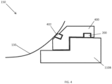
FIG. 4 , at least one of theseats 148 and 150 can include aseat body 400, aninsert 402 adapted to contact theball 130, and aseal 200. In a particular embodiment, theseat body 400 can include a resilient material, such as a metal or an alloy. Theinsert 402 can extend between theseat body 400 and contact theball 130. In an embodiment, theinsert 402 can include a polymeric material. In another embodiment, theinsert 402 can include a metal or an alloy. A biasing element, such as a spring (not illustrated) can bias theseat body 400 relative to theflow tubes seat body 400 in a direction generally toward theball 130. -
FIG. 2 includes a cross-sectional view of aseal 200 in accordance with an embodiment. While the following description is made with respect to theseal 200, it should be understood that the seal 202 can have any similar or different features as compared with theseal 200. In a particular embodiment, theseal 200 is disposed upstream of theball 130 and the seal 202 is disposed downstream of theball 130. In certain instances, theseals 200 and 202 can define rings. - In an embodiment, the
seal 200 can be adapted for use in cryogenic temperature applications. More particularly theseal 200 can be adapted for use at temperatures below - 150°C, below -175°C, below -200°C, or below -225°C. In certain instances theseal 200 can be a double piston effect seal. In other instances, theseal 200 can be a single piston effect seal. - The
seal 200 can include aresilient ring 204 having a generally annular structure defining a central axis. Theresilient ring 204 can be formed from a resilient material, such as a metal, alloy, or resilient polymer. In a particular embodiment, theresilient ring 204 can include steel. In a more particular embodiment, theresilient ring 204 can include 316 ST steel. - The
resilient ring 204 can define an inner diameter corresponding with aninner surface 206 of theresilient ring 204, an outer diameter corresponding with an outer surface 208 of theresilient ring 204, a firstaxial end 210, and a secondaxial end 212 opposite the firstaxial end 210. - In an embodiment, the
resilient ring 204 can include achamfered edge 214. In certain instances, the chamferededge 214 can extend between the outer surface 208 and the firstaxial end 210. In another instance, the chamferededge 214 can extend between the outer surface 208 and the secondaxial end 212. In yet a further instance, theresilient ring 204 can include achamfered edge 214 between the outer surface 208 and the firstaxial end 210 and achamfered edge 214 between the outer surface 208 and the secondaxial end 212. In an embodiment, the chamferededge 214 can have an angle of at least 5 degrees as measured relative to a central axis of theseal 200. In a more particular embodiment, the chamferededge 214 can have an angle of at least 10 degrees, at least 15 degrees, at least 20 degrees, at least 25 degrees, at least 30 degrees, at least 35 degrees, or at least 40 degrees. In a particular embodiment, the chamferededge 214 can have an angle of approximately 45 degrees as measured relative to the central axis of theseal 200. - In an embodiment, the
resilient ring 204 can define anengagement feature 216. In a particular embodiment, theengagement feature 216 can be disposed along a surface of theresilient ring 204. More particularly, theengagement feature 216 can be disposed along the outer surface 208 of theresilient ring 204. In the illustrated embodiment, theengagement feature 216 is shown in an axially-centered position, equidistance from the first and second axial ends 210 and 212. In another embodiment, theengagement feature 216 can be disposed closer to one of the first and second axial ends 210 or 212 as compared to the other of the first and second axial ends 210 or 212. - In an embodiment, the
engagement feature 216 can include one or more notches extending from the outer surface 208 of theresilient ring 204. In a more particular embodiment, theengagement feature 216 can include a castellated feature(s) extending from the outer surface 208 of theresilient ring 204. In another embodiment, theengagement feature 216 can include a ridge extending around a circumference of theresilient ring 204. The notch(es) or ridge can extend continuously or discontinuously around theresilient ring 204. In yet a further embodiment, theengagement feature 216 can include acutout 218. In a particular instance, thecutout 218 can extend from the outer surface 208 into theresilient ring 204. - The
engagement feature 216 can define a first axial end 220 and a secondaxial end 222. In certain instances, the first and second axial ends 220A and 220B can be parallel, or generally parallel with respect to one another. In other instances, the first and second axial ends 220A and 220B can be angularly offset from one another. For example, the first and second axial ends 220A and 220B can define negatively-sloped surfaces relative to the outer surface 208 of theresilient ring 204, thus creating acutout 218 with an increasing dimension as measured from the outer surface 208 into the body of theresilient ring 204. The first and second axial ends 220A and 220B can be spaced apart by a distance corresponding generally with a distance required to secure one or more polymer rings (described in greater detail below) with theresilient ring 204. - In certain instances, the
engagement feature 216 can have a generally same shape as measured around the circumference of theresilient ring 204. In other instances, theengagement feature 216 can have a generally same size as measured around the circumference of theresilient ring 204. In yet other instances, theengagement feature 216 can have a generally same shape and a generally same size as measured around the circumference of theresilient ring 204. - The
seal 200 includes afirst polymer ring 222 coupled with theresilient ring 204. Thefirst polymer ring 222 can be disposed adjacent to the firstaxial end 212 of theresilient ring 204. In an embodiment, thefirst polymer ring 222 can contact the firstaxial end 212 of theresilient ring 204. In a relaxed state (i.e., when theseal 200 is not yet installed in the ball valve 100), thefirst polymer ring 222 can have a diameter, as measured between an innermost location and an outermost location of thefirst polymer ring 222, that is greater than the diameter of theresilient ring 204. - According to the invention, the
first polymer ring 222 is coupled with theengagement feature 216 of theresilient ring 204. In a more particular embodiment, thefirst polymer ring 222 can include a firstcomplementary engagement feature 224 adapted to engage with theengagement feature 216 of theresilient ring 204. For example, thefirst polymer ring 222 can be coupled with theresilient ring 204 at a location adjacent to the first axial end 220 of theengagement feature 216. More particularly, thefirst polymer ring 222 can be engaged with the first axial end 220. - In an embodiment, the first
complementary engagement feature 224 can include abarb 226. Thebarb 226 can have asurface 228 adapted to couple with the first axial end 220 of theengagement feature 216. In an embodiment, thesurface 228 of thebarb 226 can have a profile similar or the same as the surface of the first axial end 220 of theengagement feature 216. In a particular embodiment, the surface of the first axial end 220 of theengagement feature 216 lies along a best fit plane generally perpendicular to the central axis of theseal 200. In a more particular embodiment, the surface of the first axial end 220 lies along a plane perpendicular to the central axis of theseal 200. Thesurface 228 of thebarb 226 can be adapted to lie parallel with the surface of the first axial end 220. - To assemble the
seal 200, thefirst polymer ring 222 andresilient ring 204 can be axially moved, such as translated, relative to one another. For example, thefirst polymer ring 222 can be axially slid relative to theresilient ring 204 in afirst direction 230 until the firstcomplementary engagement feature 224 engages theengagement feature 216. - Upon contacting the
resilient ring 204, the firstcomplementary engagement feature 224 of thefirst polymer ring 222 can deform, such as flex. In an embodiment, deformation can occur in a radially outward direction.Chamfered edge 214 can assist in installation of thefirst polymer ring 222 relative to theresilient ring 204. More specifically, the firstcomplementary engagement feature 224 can have a profile adapted to be guided by the chamferededge 214. Even more specifically, the firstcomplementary engagement feature 224 can have a chamferededge 260 adapted to contact thechamfered edge 214 of theresilient ring 204 during installation. In a particular instance, the chamferededges first polymer ring 222 with respect to theresilient ring 204. - The
first polymer ring 222 can be slid in thefirst direction 230 until the first complementary engagement feature 224 (or barb 226) arrives at theengagement feature 216. Upon arriving at theengagement feature 216, the firstcomplementary engagement feature 224 can deform, such as flex, to engage with theengagement feature 216. In an embodiment, deformation, or flexure, of the firstcomplementary engagement feature 224 upon arriving at theengagement feature 216 can occur in a radially inward direction. In a particular instance, inward deformation of the firstcomplementary engagement feature 224 can occur as a snap of the firstcomplementary engagement feature 224. In an embodiment, the snap can result in a tactile, audible, or otherwise perceptible indication to the operator performing the assembly. In such a manner, thefirst polymer ring 222 can be coupled with theresilient ring 204 and prevent from axially separating therefrom. - In an embodiment, the
first polymer ring 222 can include an energizedzone 232. In a more particular embodiment, the energizedzone 232 can be part of asame body 234 as the firstcomplementary engagement feature 224. In certain instances, the energizedzone 232 and firstcomplementary engagement feature 224 can be integral with one another, such as formed from a single monolithic body. In other instances, the energizedzone 232 can be formed from a first component and the firstcomplementary engagement feature 224 can be formed from a second component coupled with the first component. - In the illustrated embodiment, the energized
zone 232 defines a diameter, as measured between an innermost location and an outermost location of the energizedzone 232, greater than a diameter of the firstcomplementary engagement feature 224. For example, by way of a non-limiting embodiment, the diameter of the energizedzone 232 can be at least 1.01 times greater than the diameter of the firstcomplementary engagement feature 224. More particularly, the diameter of the energizedzone 232 can be at least 1.1 times greater than the diameter of the firstcomplementary engagement feature 224, at least 1.5 times greater, at least 2.0 times greater, at least 2.5 times greater, at least 3.0 times greater, or at least 3.5 times greater. In another embodiment, the diameter of the energizedzone 232 can be no greater than 50.0 times greater than the diameter of the firstcomplementary engagement feature 224, or no greater than 10.0 times greater than the diameter of the firstcomplementary engagement feature 224. - In an embodiment, the first
complementary engagement feature 224 can extend from an outer portion of the energizedzone 232. In the illustrated embodiment, anouter surface 236 of thebody 234 of thefirst polymer ring 222 can formed by a combination of the energizedzone 232 and firstcomplementary engagement feature 224. In a particular embodiment, thesurface 236 can be continuous. That is, thesurface 236 can appear featureless, smooth, or otherwise non-indicative of a transition in the cross-sectional shape of thebody 234 to an observer viewing theseal 200 after assembly. - In a particular embodiment, the energized
zone 232 can have a cross-sectional shape forming a capital E. Members, such asmiddle member 246, of the energized zone can extend toward theaxial end 240 of thefirst polymer ring 222. In an embodiment, themiddle member 246 is longer thaninner member 248 andouter member 250. - The energized
zone 232 can define one ormore cavities cavities axial end 240 of thefirst polymer ring 222. - In certain embodiments, the
first polymer ring 222 can include atransition zone 244 disposed between the energizedzone 232 and the firstcomplementary engagement feature 226. In a particular embodiment, thetransition zone 244 can have a tapering cross-sectional shape. In a more particular embodiment, thetransition zone 244 can have a chamfered edge adapted to seat relative to the chamferededge 214 of theresilient ring 204 when thefirst polymer ring 222 is engaged therewith. - At least one energizing
element 242 can be disposed within or adjacent to thefirst polymer ring 222. In an embodiment, the at least one energizingelement 242 can include at least two energizing elements, at least three energizing elements, at least four energizing elements, or at least five energizing elements. In an embodiment, the at least one energizingelement 242 can include no greater than fifty energizing elements, no greater than twenty-five energizing elements, no greater than ten energizing elements, or no greater than six energizing elements. - In a particular instance, the at least one energizing
element 242 includes a first energizing element and a second energizing element. The first energizing element can be disposed at least partially radially inside of the second energizing element. In a particular embodiment, the first and second energizing elements can lie along a straight line extending perpendicular to the central axis of thefirst polymer ring 222. - In an embodiment, the at least one energizing
element 242 can include a spring. The spring can include, for example, a spring having a round cross-sectional shape such as a helical spring, a double coiled spring, a U-shaped spring, a C-shaped spring, a V-shaped spring, or any other shaped spring adapted to provide a radially outward biasing force. In certain instances, the first and second energizing elements can have a same, or generally same, shape, spring constant, size, or other similar characteristic as compared to one another. In other instances, the first and second energizing elements can have different shapes, different spring constants, different sizes, or one or more other different characteristics as compared to one another. In a particular embodiment, the first and second energizing elements have different energizing capacities (e.g., different spring constants). More particularly, the second energizing element, disposed radially outside of the first energizing element, can have a greater energizing capacity as compared to the energizing capacity of the first energizing element. In a particular instance, use of an outer energizing element with a greater energizing capacity can enhance sealing characteristic of theseal 200 as compared to a seal with an inner-energizing element with a greater energizing capacity. - As illustrated in
FIG. 3 , in a non claimed embodiment, theseal 200 can include theresilient ring 204 and thefirst polymer ring 222 coupled together. In the non claimed embodiment, theresilient ring 204 can include half, or generally half, of theresilient ring 204 described with respect toFIG. 2 . In another embodiment, theresilient ring 204 can include a shape similar to that described with respect toFIG. 2 . - Referring again to
FIG. 2 , according to the invention, theseal 200 further includes asecond polymer ring 252. Thesecond polymer ring 252 can include any number of similar or different features as compared to thefirst polymer ring 222. In an embodiment, the first and second polymer rings 222 and 252 are symmetrical. In a more particular embodiment, the first and second polymer rings 222 and 252 reflectively symmetrical. - The
second polymer ring 252 can be disposed adjacent to theresilient ring 204. More particularly, thesecond polymer ring 252 can be disposed adjacent to the secondaxial end 212 of theresilient ring 204. - In an embodiment, the
second polymer ring 252 can include a secondcomplementary engagement feature 254 coupled with an energizedzone 256. The secondcomplementary engagement feature 254 can be adapted to couple with theresilient ring 204. More particularly, the secondcomplementary engagement feature 254 can be adapted to couple with theengagement feature 216 of theresilient ring 204. Even more particularly, in an embodiment, the secondcomplementary engagement feature 254 can include abarb 258 adapted to couple with the secondaxial end 222 of theengagement feature 216. - To assemble the
seal 200, thesecond polymer ring 252 andresilient ring 204 can be axially moved, such as translated, relative to one another. For example, thesecond polymer ring 252 can be axially slid relative to theresilient ring 204 in a second direction (opposite or generally opposite the first direction 230) until the secondcomplementary engagement feature 254 engages theengagement feature 216. - Upon contacting the
resilient ring 204, the secondcomplementary engagement feature 254 of thesecond polymer ring 252 can deform, such as flex. In an embodiment, deformation can occur in a radially outward direction.Chamfered edge 214 can assist in installation of thesecond polymer ring 252 relative to theresilient ring 204. More specifically, the secondcomplementary engagement feature 254 can have a profile adapted to be guided by the chamferededge 214. Even more specifically, the secondcomplementary engagement feature 254 can have a chamfered edge adapted to contact thechamfered edge 214 of theresilient ring 204 during installation. In a particular instance, the chamfered edge of the secondcomplementary feature 254 can lie along same, or generally same, plane as thechamfered edge 214 of theresilient ring 204. The chamfered edges can permit guiding of thesecond polymer ring 252 with respect to theresilient ring 204. - The
second polymer ring 252 can be slid in the second direction until the secondcomplementary engagement feature 254 arrives at theengagement feature 216. Upon arriving at theengagement feature 216, the secondcomplementary engagement feature 254 can deform, such as flex, to engage with theengagement feature 216. In an embodiment, deformation, or flexure, of the secondcomplementary engagement feature 254 upon arriving at theengagement feature 216 can occur in a radially inward direction. In a particular instance, inward deformation of the secondcomplementary engagement feature 254 can occur as a snap of the secondcomplementary engagement feature 254. In an embodiment, the snap can result in a tactile, audible, or otherwise perceptible indication to the operator performing the assembly. In such a manner, thesecond polymer ring 252 can be coupled with theresilient ring 204 and prevent thesecond polymer ring 252 andresilient ring 204 from axially separating. - According to the invention, the first and second polymer rings 222 and 252 contact one another when coupled with the
resilient ring 204. In an embodiment, the firstcomplementary engagement feature 224 can contact the secondcomplementary engagement feature 254. In a more particular embodiment, the firstcomplementary engagement feature 224 can contact the secondcomplementary engagement feature 254 at a location corresponding in an axial direction with theengagement feature 216. That is, for example, contact between the first and second complementary engagement features 224 and 254 can occur along a plane perpendicular to the central axis of theseal 200 and intersecting theengagement feature 216 of theresilient ring 204. In a particular embodiment, the first and second complementary engagement features 224 and 254 can contact one another a location equally, or generally equally, spaced apart from the axial ends 220 and 222 of thecomplementary engagement feature 216. - In an embodiment, the first and second complementary engagement features 222 and 254 can have at least one of a generally same cross-sectional shape, a generally same cross-sectional area, a generally same cross-sectional dimension, or any combination thereof. In a more particular embodiment, the first and second complementary engagement features 222 and 254 can have at least one of a same cross-sectional shape, a same cross-sectional area, a same cross-sectional dimension, or any combination thereof.
- In certain instances, at least one of the first and second polymer rings 222 and 252 can include a thermoplastic material. In an embodiment, at least one of the first and second polymer rings 222 and 252 can include a nylon, a polyether ether ketone (PEEK), polyether sulfone (PES), polytetrafluoroethylene (PTFE), polyimide, or an organic or inorganic composite. Further exemplary polymers include fluorinated ethylene-propylene (FEP), polyvinylidenfluoride (PVDF), polychlorotrifluoroethylene (PCTFE), ethylene chlorotrifluoroethylene (ECTFE), perfluoroalkoxy alkane (PFA), polyacetal, polybutylene terephthalate (PBT), polyethylene terephthalate (PET), polyimide (PI), polyetherimide, polyethylene (PE), polysulfone, polyamide (PA), polyphenylene oxide, polyphenylene sulfide (PPS), polyurethane, polyester, liquid crystal polymers (LCP), or any combination thereof.
- In an embodiment, at least one of the first and second polymer rings 222 and 254, can include a filler. Exemplary fillers include glass fibers, carbon fibers, silicon, PEEK, aromatic polyester, carbon particles, bronze, fluoropolymers, thermoplastic fillers, aluminum oxide, polyamidimide (PAI), PPS, polyphenylene sulfone (PPSO2), LCP, aromatic polyesters, molybdenum disulfide, tungsten disulfide, graphite, grapheme, expanded graphite, boron nitrade, talc, calcium fluoride, or any combination thereof. Additionally, the filler can include alumina, silica, titanium dioxide, calcium fluoride, boron nitride, mica, Wollastonite, silicon carbide, silicon nitride, zirconia, carbon black, pigments, or any combination thereof.
- In an embodiment, the first and second polymer rings 222 and 254 can be parts of a single polymer element. That is, for example, the first and second polymer rings 222 and 254 can be integral with one another. More specifically, the first and second polymer rings 222 and 254 can be formed from, or include, a single body.
- Note that not all of the activities described above in the general description or the examples are required, that a portion of a specific activity may not be required, and that one or more further activities may be performed in addition to those described. Still further, the order in which activities are listed is not necessarily the order in which they are performed.
- Benefits, other advantages, and solutions to problems have been described above with regard to specific embodiments. However, the benefits, advantages, solutions to problems, and any feature(s) that may cause any benefit, advantage, or solution to occur or become more pronounced are not to be construed as a critical, required, or essential feature of any or all the claims.
Claims (13)
- A seal (200) for a ball valve (100) comprising:a resilient ring (204) defining an engagement feature (216);a first polymer ring (222) disposed adjacent to a first axial end (210) of the resilient ring (204) and coupled with the engagement feature (216); anda second polymer ring (252) disposed adjacent to a second axial end (212) of the resilient ring (204) and coupled with the engagement feature (216),wherein the first polymer ring (222) contacts the second polymer ring (252) at an axial location corresponding with the engagement feature (216).
- The seal (200) of claim 1, wherein the first polymer seal ring (222) comprises:an energized zone (232) including at least one energizing element (242); andan engagement feature (224) adapted to engage with the engagement feature (216) of the resilient ring (204).
- A method of assembling a seal assembly comprising:axially sliding a first polymer ring (222) relative to a resilient ring (204) in a first direction until an engagement feature (216) of the resilient ring (204) engages a first complementary engagement feature (224) on the first polymer ring (222), andaxially sliding a second polymer ring (252) relative to the resilient ring (204) in a second direction until the engagement feature (216) engages a second complementary engagement feature (254) on the second polymer ring (252), wherein the first polymer ring (222) contacts the second polymer ring (252) at an axial location corresponding with the engagement feature (216).
- The seal (200) of claim 1, wherein the engagement feature (216) comprises a notch, a ridge, a cutout, a castellation, or any combination thereof.
- The seal (200) of claim 1, wherein the engagement feature (216) is disposed along an outer diameter of the resilient ring (204).
- The seal (200) of claim 1, wherein the first polymer ring (222) comprises a body defining a first corresponding engagement feature (224) and an energized zone (232) coupled with the first corresponding engagement feature (224).
- The seal (200) of claim 6, wherein the energized zone (232) comprises at least one energizing element (242).
- The seal (200) of claim 7, wherein the energized zone (232) comprises at least one spring disposed at least partially within the body of the first polymer ring (222).
- The seal (200), or method of claims 1 or 3, wherein the resilient ring (204) comprises an inner diameter, an outer diameter, a first axial end (210), and a second axial end (212), and wherein an edge (214) between at least one of the first and second axial ends (210, 212) and the outer diameter comprises a chamfer.
- The seal (200) of claim 1, wherein the engagement feature (216) defines a first axial end (220A) and a second axial end (220B), wherein the first polymer ring (222) is coupled with the resilient ring (204) adjacent to the first axial end (220A), and wherein the second polymer ring (252) is coupled with the resilient ring (204) adjacent to the second axial end (220B).
- The seal (200) of claim 1, wherein the second polymer ring (252) comprises a second corresponding engagement feature (254) adapted to engage with the engagement feature (216) of the resilient ring (204).
- The seal (200) of claim 1, wherein the first polymer ring (222) comprises a first corresponding engagement feature (224) adapted to engage with the engagement feature (216) of the resilient ring (204).
- The seal (200) of claim 12, wherein the first corresponding engagement feature (224) comprises a barb adapted to engage with the engagement feature (216) of the resilient ring (204).
Applications Claiming Priority (2)
| Application Number | Priority Date | Filing Date | Title |
|---|---|---|---|
| US201862714315P | 2018-08-03 | 2018-08-03 | |
| PCT/US2019/044295 WO2020028469A1 (en) | 2018-08-03 | 2019-07-31 | Ball valve seal |
Publications (3)
| Publication Number | Publication Date |
|---|---|
| EP3830456A1 EP3830456A1 (en) | 2021-06-09 |
| EP3830456A4 EP3830456A4 (en) | 2022-05-11 |
| EP3830456B1 true EP3830456B1 (en) | 2024-09-04 |
Family
ID=69228432
Family Applications (1)
| Application Number | Title | Priority Date | Filing Date |
|---|---|---|---|
| EP19843861.6A Active EP3830456B1 (en) | 2018-08-03 | 2019-07-31 | Ball valve seal |
Country Status (7)
| Country | Link |
|---|---|
| US (1) | US11448321B2 (en) |
| EP (1) | EP3830456B1 (en) |
| CN (1) | CN112534165B (en) |
| DK (1) | DK3830456T3 (en) |
| ES (1) | ES2992674T3 (en) |
| RU (1) | RU2771113C1 (en) |
| WO (1) | WO2020028469A1 (en) |
Families Citing this family (3)
| Publication number | Priority date | Publication date | Assignee | Title |
|---|---|---|---|---|
| US20210254716A1 (en) * | 2020-02-19 | 2021-08-19 | Saint-Gobain Performance Plastics Corporation | Flexible cryogenic seal |
| WO2022200641A1 (en) * | 2021-03-25 | 2022-09-29 | Bac Valves, S.A. | Two-way ball valve with cryogenic seat |
| US12510167B2 (en) * | 2024-02-29 | 2025-12-30 | SCV Valve, LLC | Systems and methods for double piston effect ball valves |
Family Cites Families (45)
| Publication number | Priority date | Publication date | Assignee | Title |
|---|---|---|---|---|
| US3097823A (en) * | 1959-10-28 | 1963-07-16 | Kaiser Rudolf | Shutoff cock having a spherical plug |
| JPS5773458U (en) | 1980-10-22 | 1982-05-06 | ||
| JPS6219420A (en) | 1985-07-18 | 1987-01-28 | Kubota Ltd | Mold for manufacturing valve seats |
| US6254275B1 (en) * | 1995-12-19 | 2001-07-03 | Smith International, Inc. | Sealed bearing drill bit with dual-seal configuration and fluid-cleaning capability |
| RU2103581C1 (en) * | 1996-09-25 | 1998-01-27 | Акционерное общество закрытого типа "Ярдос" | Ball cock seal |
| JP3342826B2 (en) | 1997-11-27 | 2002-11-11 | 株式会社クボタ | Ball valve seat ring |
| US5992856A (en) * | 1997-12-12 | 1999-11-30 | Bal Seal Engineering Company, Inc. | Rotary, reciprocating seals with double spring and separating band rings |
| US6547250B1 (en) * | 2000-08-21 | 2003-04-15 | Westport Research Inc. | Seal assembly with two sealing mechanisms for providing static and dynamic sealing |
| WO2002079676A2 (en) * | 2001-03-28 | 2002-10-10 | Balseal Engineering Co., Inc. | Media isolation seal system |
| US20060022414A1 (en) * | 2004-07-30 | 2006-02-02 | Balsells Peter J | Rotary cartridge seals with composite retainer |
| JP5045869B2 (en) | 2005-12-08 | 2012-10-10 | Nok株式会社 | Lip type seal |
| US8328202B2 (en) * | 2007-12-07 | 2012-12-11 | Bal Seal Engineering, Inc. | Seal assembly for high pressure dynamic and static services |
| KR101583653B1 (en) * | 2008-05-15 | 2016-01-21 | 이글 고우교 가부시기가이샤 | Lip type seal |
| US8096559B2 (en) * | 2008-05-23 | 2012-01-17 | Bal Seal Engineering, Inc. | Rotary seals |
| DE102008033251A1 (en) * | 2008-07-15 | 2010-01-21 | Pflüger, Peter, Dipl.-Ing. | Rear sealing for oil-lubricated stern tube for ship in e.g. sea, has stagnant and rotating sliding rings sealed against water and stern tube oil, respectively, where sliding rings are separated by air space |
| US8215646B2 (en) | 2008-08-28 | 2012-07-10 | Castleman Larry J | Seal assembly |
| US8544850B2 (en) * | 2009-03-23 | 2013-10-01 | Bal Seal Engineering, Inc. | Seal assemblies for movable and static shafts |
| US10247307B2 (en) * | 2009-03-23 | 2019-04-02 | Bal Seal Engineering, Inc. | Interlocking composite seals |
| US10520091B2 (en) * | 2009-07-08 | 2019-12-31 | Bal Seal Engineering, Inc. | Double direction seal with locking |
| US8820708B2 (en) * | 2009-07-17 | 2014-09-02 | Fisher Controls International Llc | Seal assemblies for use with fluid valves |
| US8684362B2 (en) * | 2009-08-12 | 2014-04-01 | Bal Seal Engineering, Inc. | Cartridge seal assemblies and associated methods |
| CA2781719A1 (en) * | 2009-12-11 | 2011-06-16 | Saint-Gobain Performance Plastics Corporation | System, method and apparatus for spring-energized dynamic sealing assembly |
| EP2341269A1 (en) | 2009-12-22 | 2011-07-06 | Valbart S.r.l. | Trunnion-mounted ball valve with reverse-piston effect |
| US8910921B2 (en) * | 2011-10-27 | 2014-12-16 | Aegis Flow Technologies, L.L.C. | Valve and stem sealing assembly |
| CN105065811B (en) * | 2012-06-25 | 2017-05-24 | 株式会社久保田 | Pressing ring, coupling, and valve |
| CN102748497B (en) | 2012-07-16 | 2014-08-06 | 圣博莱阀门有限公司 | Ultra-low temperature top-mounted type ball valve |
| US20140175319A1 (en) * | 2012-12-20 | 2014-06-26 | Fisher Controls International Llc | Multi-section valve bodies having face seals |
| US9234591B2 (en) * | 2013-03-15 | 2016-01-12 | Bal Seal Engineering, Inc. | High pressure lip seals with anti-extrusion and anti-galling properties and related methods |
| US9816625B2 (en) * | 2013-04-26 | 2017-11-14 | Flowserve Management Company | Seal carriers for ball valves, ball valve assemblies including such seal carriers, and related methods |
| US10047261B2 (en) * | 2013-05-03 | 2018-08-14 | Fmc Kongsberg Subsea As | Elastomeric seal |
| RU138591U1 (en) * | 2013-10-09 | 2014-03-20 | Павел Эдуардович Мельников | SEALING ASSEMBLY OF BALL VALVE ELEMENT |
| CN203703226U (en) | 2013-12-18 | 2014-07-09 | 雷蒙德(北京)阀门制造有限公司 | Double-piston double-blocking hard sealing valve seat with metal C-shaped ring sealing structure |
| KR101527569B1 (en) | 2014-01-06 | 2015-06-09 | 제일 이엔에스 주식회사 | Manufacturing method of rubber o-ring type gasket having kammprofile |
| CN103742672B (en) | 2014-01-27 | 2017-11-14 | 苏州纽威阀门股份有限公司 | top-loading ball valve |
| CN104089044B (en) | 2014-07-15 | 2017-01-11 | 合肥通用机械研究院 | LNG ultra-low temperature top-mounting type ball valve seat capable of achieving pre-tightening force fine tuning and on-line disassembling |
| CN204420171U (en) | 2014-12-24 | 2015-06-24 | 四川精控阀门制造有限公司 | Two way sealed valve seat construction and ultralow temperature fill formula fixing ball valve |
| EP3040588B1 (en) * | 2014-12-31 | 2017-05-03 | Cameron International Corporation | Double piston effect lip seal seating assemblies |
| US10184564B2 (en) * | 2015-02-02 | 2019-01-22 | Bal Seal Engineering, Inc. | Seal assemblies and related methods |
| CN205036882U (en) * | 2015-09-01 | 2016-02-17 | 圣戈班高功能塑料(上海)有限公司 | Two way seal piece and be equipped with ball valve of this two way seal piece |
| WO2017141221A1 (en) | 2016-02-18 | 2017-08-24 | Gasket International S.R.L. | Sealing assembly for ball valves and ball valve comprising such a sealing assembly |
| CN105782484A (en) | 2016-04-19 | 2016-07-20 | 潘明尧 | LNG ultralow-temperature top installing type ball valve |
| EP3242061B1 (en) * | 2016-05-04 | 2019-03-06 | Hyundai Motor Company | Coolant control valve unit having sealing structure |
| US10520092B2 (en) * | 2016-10-24 | 2019-12-31 | Bal Seal Engineering, Inc. | Seal assemblies for extreme temperatures and related methods |
| CN207178760U (en) | 2017-09-28 | 2018-04-03 | 河源孚罗泰自控阀门有限公司 | A kind of low temperature hard seal ball valve |
| CN108150653A (en) * | 2017-12-25 | 2018-06-12 | 陈旭明 | A kind of five lip combination seals |
-
2019
- 2019-07-31 EP EP19843861.6A patent/EP3830456B1/en active Active
- 2019-07-31 WO PCT/US2019/044295 patent/WO2020028469A1/en not_active Ceased
- 2019-07-31 US US16/527,394 patent/US11448321B2/en active Active
- 2019-07-31 RU RU2021105036A patent/RU2771113C1/en active
- 2019-07-31 DK DK19843861.6T patent/DK3830456T3/en active
- 2019-07-31 ES ES19843861T patent/ES2992674T3/en active Active
- 2019-07-31 CN CN201980051602.0A patent/CN112534165B/en active Active
Also Published As
| Publication number | Publication date |
|---|---|
| ES2992674T3 (en) | 2024-12-16 |
| EP3830456A4 (en) | 2022-05-11 |
| WO2020028469A1 (en) | 2020-02-06 |
| CN112534165A (en) | 2021-03-19 |
| US20200041002A1 (en) | 2020-02-06 |
| EP3830456A1 (en) | 2021-06-09 |
| CN112534165B (en) | 2023-01-24 |
| US11448321B2 (en) | 2022-09-20 |
| DK3830456T3 (en) | 2024-10-14 |
| RU2771113C1 (en) | 2022-04-26 |
Similar Documents
| Publication | Publication Date | Title |
|---|---|---|
| US11708910B2 (en) | Seals | |
| US8181970B2 (en) | Unitized bi-directional seal assembly | |
| US11448321B2 (en) | Ball valve seal | |
| EP2385281B1 (en) | Ball valve seat seal | |
| US20160319936A1 (en) | Seals | |
| CN104048059B (en) | Composite power valve seal assembly for high-temperature control valve | |
| JP2013511012A (en) | System, method and apparatus for a spring activated dynamic sealing assembly | |
| US20190309853A1 (en) | Scraper ring | |
| KR20210024643A (en) | Torque assemblies and methods of making and using them | |
| CN103998837A (en) | Sealing system for industrial valves, particularly for ball valves, and valve comprising said system | |
| US20150083955A1 (en) | Bi-directional rotary valve | |
| KR20200059322A (en) | Plain bearing assembly | |
| US20230375088A1 (en) | Energizing element and methods of making and using the same | |
| US20210254716A1 (en) | Flexible cryogenic seal | |
| US12060943B2 (en) | Seals and methods of making and using the same | |
| US10267424B2 (en) | Butterfly valve seat with seat cover | |
| WO2023215463A1 (en) | Seals and methods of making and using the same | |
| US12523301B2 (en) | Seal and method of using and making the same |
Legal Events
| Date | Code | Title | Description |
|---|---|---|---|
| STAA | Information on the status of an ep patent application or granted ep patent |
Free format text: STATUS: THE INTERNATIONAL PUBLICATION HAS BEEN MADE |
|
| PUAI | Public reference made under article 153(3) epc to a published international application that has entered the european phase |
Free format text: ORIGINAL CODE: 0009012 |
|
| STAA | Information on the status of an ep patent application or granted ep patent |
Free format text: STATUS: REQUEST FOR EXAMINATION WAS MADE |
|
| 17P | Request for examination filed |
Effective date: 20210211 |
|
| AK | Designated contracting states |
Kind code of ref document: A1 Designated state(s): AL AT BE BG CH CY CZ DE DK EE ES FI FR GB GR HR HU IE IS IT LI LT LU LV MC MK MT NL NO PL PT RO RS SE SI SK SM TR |
|
| DAV | Request for validation of the european patent (deleted) | ||
| DAX | Request for extension of the european patent (deleted) | ||
| A4 | Supplementary search report drawn up and despatched |
Effective date: 20220411 |
|
| RIC1 | Information provided on ipc code assigned before grant |
Ipc: F16J 15/3236 20160101ALI20220405BHEP Ipc: F16J 15/3212 20160101ALI20220405BHEP Ipc: F16J 15/16 20060101ALI20220405BHEP Ipc: F16J 15/12 20060101ALI20220405BHEP Ipc: F16J 15/06 20060101ALI20220405BHEP Ipc: F16J 15/02 20060101ALI20220405BHEP Ipc: F16K 5/20 20060101ALI20220405BHEP Ipc: F16K 5/06 20060101AFI20220405BHEP |
|
| GRAP | Despatch of communication of intention to grant a patent |
Free format text: ORIGINAL CODE: EPIDOSNIGR1 |
|
| STAA | Information on the status of an ep patent application or granted ep patent |
Free format text: STATUS: GRANT OF PATENT IS INTENDED |
|
| INTG | Intention to grant announced |
Effective date: 20240409 |
|
| GRAS | Grant fee paid |
Free format text: ORIGINAL CODE: EPIDOSNIGR3 |
|
| GRAA | (expected) grant |
Free format text: ORIGINAL CODE: 0009210 |
|
| STAA | Information on the status of an ep patent application or granted ep patent |
Free format text: STATUS: THE PATENT HAS BEEN GRANTED |
|
| RIN1 | Information on inventor provided before grant (corrected) |
Inventor name: ROUSSEAU, FILIP Inventor name: VANVAERENBERGH, ANDREAS Inventor name: NUNNA, SHABARISH Inventor name: MAFFEZZOLI, ANDREA Inventor name: BURLOT, PHILIPPE Inventor name: DUBOIS, HERMAN, M. Inventor name: TITTONEL, GABRIELE Inventor name: PROOST, BENNY Inventor name: KUSTERMANS, JAN |
|
| AK | Designated contracting states |
Kind code of ref document: B1 Designated state(s): AL AT BE BG CH CY CZ DE DK EE ES FI FR GB GR HR HU IE IS IT LI LT LU LV MC MK MT NL NO PL PT RO RS SE SI SK SM TR |
|
| REG | Reference to a national code |
Ref country code: GB Ref legal event code: FG4D |
|
| REG | Reference to a national code |
Ref country code: CH Ref legal event code: EP |
|
| P01 | Opt-out of the competence of the unified patent court (upc) registered |
Free format text: CASE NUMBER: APP_47849/2024 Effective date: 20240820 |
|
| REG | Reference to a national code |
Ref country code: IE Ref legal event code: FG4D |
|
| REG | Reference to a national code |
Ref country code: DE Ref legal event code: R096 Ref document number: 602019058451 Country of ref document: DE |
|
| REG | Reference to a national code |
Ref country code: DK Ref legal event code: T3 Effective date: 20241010 |
|
| REG | Reference to a national code |
Ref country code: NL Ref legal event code: FP |
|
| REG | Reference to a national code |
Ref country code: SE Ref legal event code: TRGR |
|
| REG | Reference to a national code |
Ref country code: ES Ref legal event code: FG2A Ref document number: 2992674 Country of ref document: ES Kind code of ref document: T3 Effective date: 20241216 |
|
| REG | Reference to a national code |
Ref country code: LT Ref legal event code: MG9D |
|
| PG25 | Lapsed in a contracting state [announced via postgrant information from national office to epo] |
Ref country code: FI Free format text: LAPSE BECAUSE OF FAILURE TO SUBMIT A TRANSLATION OF THE DESCRIPTION OR TO PAY THE FEE WITHIN THE PRESCRIBED TIME-LIMIT Effective date: 20240904 Ref country code: GR Free format text: LAPSE BECAUSE OF FAILURE TO SUBMIT A TRANSLATION OF THE DESCRIPTION OR TO PAY THE FEE WITHIN THE PRESCRIBED TIME-LIMIT Effective date: 20241205 Ref country code: PL Free format text: LAPSE BECAUSE OF FAILURE TO SUBMIT A TRANSLATION OF THE DESCRIPTION OR TO PAY THE FEE WITHIN THE PRESCRIBED TIME-LIMIT Effective date: 20240904 |
|
| PG25 | Lapsed in a contracting state [announced via postgrant information from national office to epo] |
Ref country code: BG Free format text: LAPSE BECAUSE OF FAILURE TO SUBMIT A TRANSLATION OF THE DESCRIPTION OR TO PAY THE FEE WITHIN THE PRESCRIBED TIME-LIMIT Effective date: 20240904 |
|
| PG25 | Lapsed in a contracting state [announced via postgrant information from national office to epo] |
Ref country code: LV Free format text: LAPSE BECAUSE OF FAILURE TO SUBMIT A TRANSLATION OF THE DESCRIPTION OR TO PAY THE FEE WITHIN THE PRESCRIBED TIME-LIMIT Effective date: 20240904 |
|
| PG25 | Lapsed in a contracting state [announced via postgrant information from national office to epo] |
Ref country code: HR Free format text: LAPSE BECAUSE OF FAILURE TO SUBMIT A TRANSLATION OF THE DESCRIPTION OR TO PAY THE FEE WITHIN THE PRESCRIBED TIME-LIMIT Effective date: 20240904 |
|
| PG25 | Lapsed in a contracting state [announced via postgrant information from national office to epo] |
Ref country code: PL Free format text: LAPSE BECAUSE OF FAILURE TO SUBMIT A TRANSLATION OF THE DESCRIPTION OR TO PAY THE FEE WITHIN THE PRESCRIBED TIME-LIMIT Effective date: 20240904 Ref country code: LV Free format text: LAPSE BECAUSE OF FAILURE TO SUBMIT A TRANSLATION OF THE DESCRIPTION OR TO PAY THE FEE WITHIN THE PRESCRIBED TIME-LIMIT Effective date: 20240904 Ref country code: HR Free format text: LAPSE BECAUSE OF FAILURE TO SUBMIT A TRANSLATION OF THE DESCRIPTION OR TO PAY THE FEE WITHIN THE PRESCRIBED TIME-LIMIT Effective date: 20240904 Ref country code: GR Free format text: LAPSE BECAUSE OF FAILURE TO SUBMIT A TRANSLATION OF THE DESCRIPTION OR TO PAY THE FEE WITHIN THE PRESCRIBED TIME-LIMIT Effective date: 20241205 Ref country code: FI Free format text: LAPSE BECAUSE OF FAILURE TO SUBMIT A TRANSLATION OF THE DESCRIPTION OR TO PAY THE FEE WITHIN THE PRESCRIBED TIME-LIMIT Effective date: 20240904 Ref country code: BG Free format text: LAPSE BECAUSE OF FAILURE TO SUBMIT A TRANSLATION OF THE DESCRIPTION OR TO PAY THE FEE WITHIN THE PRESCRIBED TIME-LIMIT Effective date: 20240904 |
|
| REG | Reference to a national code |
Ref country code: AT Ref legal event code: MK05 Ref document number: 1720711 Country of ref document: AT Kind code of ref document: T Effective date: 20240904 |
|
| PG25 | Lapsed in a contracting state [announced via postgrant information from national office to epo] |
Ref country code: PT Free format text: LAPSE BECAUSE OF FAILURE TO SUBMIT A TRANSLATION OF THE DESCRIPTION OR TO PAY THE FEE WITHIN THE PRESCRIBED TIME-LIMIT Effective date: 20250106 Ref country code: IS Free format text: LAPSE BECAUSE OF FAILURE TO SUBMIT A TRANSLATION OF THE DESCRIPTION OR TO PAY THE FEE WITHIN THE PRESCRIBED TIME-LIMIT Effective date: 20250104 |
|
| PG25 | Lapsed in a contracting state [announced via postgrant information from national office to epo] |
Ref country code: RO Free format text: LAPSE BECAUSE OF FAILURE TO SUBMIT A TRANSLATION OF THE DESCRIPTION OR TO PAY THE FEE WITHIN THE PRESCRIBED TIME-LIMIT Effective date: 20240904 Ref country code: SM Free format text: LAPSE BECAUSE OF FAILURE TO SUBMIT A TRANSLATION OF THE DESCRIPTION OR TO PAY THE FEE WITHIN THE PRESCRIBED TIME-LIMIT Effective date: 20240904 |
|
| PG25 | Lapsed in a contracting state [announced via postgrant information from national office to epo] |
Ref country code: EE Free format text: LAPSE BECAUSE OF FAILURE TO SUBMIT A TRANSLATION OF THE DESCRIPTION OR TO PAY THE FEE WITHIN THE PRESCRIBED TIME-LIMIT Effective date: 20240904 Ref country code: AT Free format text: LAPSE BECAUSE OF FAILURE TO SUBMIT A TRANSLATION OF THE DESCRIPTION OR TO PAY THE FEE WITHIN THE PRESCRIBED TIME-LIMIT Effective date: 20240904 |
|
| PG25 | Lapsed in a contracting state [announced via postgrant information from national office to epo] |
Ref country code: CZ Free format text: LAPSE BECAUSE OF FAILURE TO SUBMIT A TRANSLATION OF THE DESCRIPTION OR TO PAY THE FEE WITHIN THE PRESCRIBED TIME-LIMIT Effective date: 20240904 |
|
| PG25 | Lapsed in a contracting state [announced via postgrant information from national office to epo] |
Ref country code: SK Free format text: LAPSE BECAUSE OF FAILURE TO SUBMIT A TRANSLATION OF THE DESCRIPTION OR TO PAY THE FEE WITHIN THE PRESCRIBED TIME-LIMIT Effective date: 20240904 |
|
| REG | Reference to a national code |
Ref country code: DE Ref legal event code: R097 Ref document number: 602019058451 Country of ref document: DE |
|
| PGFP | Annual fee paid to national office [announced via postgrant information from national office to epo] |
Ref country code: GB Payment date: 20250619 Year of fee payment: 7 Ref country code: DK Payment date: 20250619 Year of fee payment: 7 |
|
| PLBE | No opposition filed within time limit |
Free format text: ORIGINAL CODE: 0009261 |
|
| STAA | Information on the status of an ep patent application or granted ep patent |
Free format text: STATUS: NO OPPOSITION FILED WITHIN TIME LIMIT |
|
| PGFP | Annual fee paid to national office [announced via postgrant information from national office to epo] |
Ref country code: NO Payment date: 20250623 Year of fee payment: 7 |
|
| PGFP | Annual fee paid to national office [announced via postgrant information from national office to epo] |
Ref country code: NL Payment date: 20250620 Year of fee payment: 7 Ref country code: BE Payment date: 20250619 Year of fee payment: 7 |
|
| PGFP | Annual fee paid to national office [announced via postgrant information from national office to epo] |
Ref country code: FR Payment date: 20250620 Year of fee payment: 7 |
|
| PGFP | Annual fee paid to national office [announced via postgrant information from national office to epo] |
Ref country code: SE Payment date: 20250619 Year of fee payment: 7 |
|
| 26N | No opposition filed |
Effective date: 20250605 |
|
| PGFP | Annual fee paid to national office [announced via postgrant information from national office to epo] |
Ref country code: ES Payment date: 20250801 Year of fee payment: 7 |
|
| PGFP | Annual fee paid to national office [announced via postgrant information from national office to epo] |
Ref country code: DE Payment date: 20250620 Year of fee payment: 7 |
|
| PGFP | Annual fee paid to national office [announced via postgrant information from national office to epo] |
Ref country code: IT Payment date: 20250619 Year of fee payment: 7 |
|
| REG | Reference to a national code |
Ref country code: CH Ref legal event code: H13 Free format text: ST27 STATUS EVENT CODE: U-0-0-H10-H13 (AS PROVIDED BY THE NATIONAL OFFICE) Effective date: 20260224 |
|
| PG25 | Lapsed in a contracting state [announced via postgrant information from national office to epo] |
Ref country code: LU Free format text: LAPSE BECAUSE OF NON-PAYMENT OF DUE FEES Effective date: 20250731 |
|
| PG25 | Lapsed in a contracting state [announced via postgrant information from national office to epo] |
Ref country code: CH Free format text: LAPSE BECAUSE OF NON-PAYMENT OF DUE FEES Effective date: 20250731 |