EP3830441B1 - Method for measuring wear of a clutch and related maintenance method, assembly comprising a clutch and a wear measurement device, and vehicle - Google Patents
Method for measuring wear of a clutch and related maintenance method, assembly comprising a clutch and a wear measurement device, and vehicle Download PDFInfo
- Publication number
- EP3830441B1 EP3830441B1 EP18750157.2A EP18750157A EP3830441B1 EP 3830441 B1 EP3830441 B1 EP 3830441B1 EP 18750157 A EP18750157 A EP 18750157A EP 3830441 B1 EP3830441 B1 EP 3830441B1
- Authority
- EP
- European Patent Office
- Prior art keywords
- actuation device
- contact
- contact part
- pressurized fluid
- wear
- Prior art date
- Legal status (The legal status is an assumption and is not a legal conclusion. Google has not performed a legal analysis and makes no representation as to the accuracy of the status listed.)
- Active
Links
Images


Classifications
-
- F—MECHANICAL ENGINEERING; LIGHTING; HEATING; WEAPONS; BLASTING
- F16—ENGINEERING ELEMENTS AND UNITS; GENERAL MEASURES FOR PRODUCING AND MAINTAINING EFFECTIVE FUNCTIONING OF MACHINES OR INSTALLATIONS; THERMAL INSULATION IN GENERAL
- F16D—COUPLINGS FOR TRANSMITTING ROTATION; CLUTCHES; BRAKES
- F16D48/00—External control of clutches
- F16D48/06—Control by electric or electronic means, e.g. of fluid pressure
-
- F—MECHANICAL ENGINEERING; LIGHTING; HEATING; WEAPONS; BLASTING
- F16—ENGINEERING ELEMENTS AND UNITS; GENERAL MEASURES FOR PRODUCING AND MAINTAINING EFFECTIVE FUNCTIONING OF MACHINES OR INSTALLATIONS; THERMAL INSULATION IN GENERAL
- F16D—COUPLINGS FOR TRANSMITTING ROTATION; CLUTCHES; BRAKES
- F16D48/00—External control of clutches
- F16D48/06—Control by electric or electronic means, e.g. of fluid pressure
- F16D48/066—Control of fluid pressure, e.g. using an accumulator
-
- F—MECHANICAL ENGINEERING; LIGHTING; HEATING; WEAPONS; BLASTING
- F16—ENGINEERING ELEMENTS AND UNITS; GENERAL MEASURES FOR PRODUCING AND MAINTAINING EFFECTIVE FUNCTIONING OF MACHINES OR INSTALLATIONS; THERMAL INSULATION IN GENERAL
- F16D—COUPLINGS FOR TRANSMITTING ROTATION; CLUTCHES; BRAKES
- F16D25/00—Fluid-actuated clutches
- F16D25/06—Fluid-actuated clutches in which the fluid actuates a piston incorporated in, i.e. rotating with the clutch
- F16D25/062—Fluid-actuated clutches in which the fluid actuates a piston incorporated in, i.e. rotating with the clutch the clutch having friction surfaces
- F16D25/063—Fluid-actuated clutches in which the fluid actuates a piston incorporated in, i.e. rotating with the clutch the clutch having friction surfaces with clutch members exclusively moving axially
- F16D25/0635—Fluid-actuated clutches in which the fluid actuates a piston incorporated in, i.e. rotating with the clutch the clutch having friction surfaces with clutch members exclusively moving axially with flat friction surfaces, e.g. discs
-
- F—MECHANICAL ENGINEERING; LIGHTING; HEATING; WEAPONS; BLASTING
- F16—ENGINEERING ELEMENTS AND UNITS; GENERAL MEASURES FOR PRODUCING AND MAINTAINING EFFECTIVE FUNCTIONING OF MACHINES OR INSTALLATIONS; THERMAL INSULATION IN GENERAL
- F16D—COUPLINGS FOR TRANSMITTING ROTATION; CLUTCHES; BRAKES
- F16D2500/00—External control of clutches by electric or electronic means
- F16D2500/10—System to be controlled
- F16D2500/102—Actuator
- F16D2500/1028—Pneumatic
-
- F—MECHANICAL ENGINEERING; LIGHTING; HEATING; WEAPONS; BLASTING
- F16—ENGINEERING ELEMENTS AND UNITS; GENERAL MEASURES FOR PRODUCING AND MAINTAINING EFFECTIVE FUNCTIONING OF MACHINES OR INSTALLATIONS; THERMAL INSULATION IN GENERAL
- F16D—COUPLINGS FOR TRANSMITTING ROTATION; CLUTCHES; BRAKES
- F16D2500/00—External control of clutches by electric or electronic means
- F16D2500/10—System to be controlled
- F16D2500/104—Clutch
- F16D2500/10443—Clutch type
- F16D2500/1045—Friction clutch
-
- F—MECHANICAL ENGINEERING; LIGHTING; HEATING; WEAPONS; BLASTING
- F16—ENGINEERING ELEMENTS AND UNITS; GENERAL MEASURES FOR PRODUCING AND MAINTAINING EFFECTIVE FUNCTIONING OF MACHINES OR INSTALLATIONS; THERMAL INSULATION IN GENERAL
- F16D—COUPLINGS FOR TRANSMITTING ROTATION; CLUTCHES; BRAKES
- F16D2500/00—External control of clutches by electric or electronic means
- F16D2500/30—Signal inputs
- F16D2500/302—Signal inputs from the actuator
- F16D2500/3024—Pressure
-
- F—MECHANICAL ENGINEERING; LIGHTING; HEATING; WEAPONS; BLASTING
- F16—ENGINEERING ELEMENTS AND UNITS; GENERAL MEASURES FOR PRODUCING AND MAINTAINING EFFECTIVE FUNCTIONING OF MACHINES OR INSTALLATIONS; THERMAL INSULATION IN GENERAL
- F16D—COUPLINGS FOR TRANSMITTING ROTATION; CLUTCHES; BRAKES
- F16D2500/00—External control of clutches by electric or electronic means
- F16D2500/50—Problem to be solved by the control system
- F16D2500/502—Relating the clutch
- F16D2500/5023—Determination of the clutch wear
-
- F—MECHANICAL ENGINEERING; LIGHTING; HEATING; WEAPONS; BLASTING
- F16—ENGINEERING ELEMENTS AND UNITS; GENERAL MEASURES FOR PRODUCING AND MAINTAINING EFFECTIVE FUNCTIONING OF MACHINES OR INSTALLATIONS; THERMAL INSULATION IN GENERAL
- F16D—COUPLINGS FOR TRANSMITTING ROTATION; CLUTCHES; BRAKES
- F16D2500/00—External control of clutches by electric or electronic means
- F16D2500/70—Details about the implementation of the control system
- F16D2500/704—Output parameters from the control unit; Target parameters to be controlled
- F16D2500/70402—Actuator parameters
- F16D2500/7041—Position
Definitions
- the invention relates to a method for measuring wear of a clutch and to a related maintenance method, assembly comprising a clutch and a wear measurement device, and vehicle.
- the invention applies in particular to maintenance of the pneumatic clutch of an air compressor of a pneumatic system of a vehicle.
- the pneumatic clutch is generally used to disconnect the air compressor from the engine when pressure in the pneumatic system is sufficient and it is no longer necessary to supply compressed air.
- a pneumatic system is disclosed in US2017/321765 .
- the pneumatic clutch is subjected to wear.
- the invention aims at meeting such need.
- the invention provides a method for measuring wear of a clutch, the clutch comprising:
- the invention makes use of such modification of the gap between the contact part of the actuation device and the biasing member to quantify wear of the friction disks of the interface member and the first shaft member.
- the invention also makes use of actuation of the contact part of the actuation device by injection of pressurized fluid to determine the gap between the contact part of the actuation device and the biasing member.
- the method enables wear of the clutch to be measured in a reliable and simple manner directly on the clutch.
- the method does not require any disassembling which save time. Wear of the clutch may be checked periodically during maintenance of the vehicle so as to anticipate possible dysfunction. Where needed, the method could be used to monitor continuously wear of the clutch.
- vacuum is applied to the pressure chamber of the actuation device.
- the input volume may be greater than or equal to a maximum volume on a full range of wear to have the contact part of the actuation device and the biasing member in contact, and lower than or equal to a minimum volume on the full range of wear to have the interface member in the disengaged position.
- the input volume may be greater than or equal to a maximum volume on a full range of wear to have the contact part of the actuation device and the biasing member in contact, and lower than or equal to a minimum volume on the full range of wear to have the interface member in the disengaged position.
- the casing may include:
- the assembly comprises an air compressor 1 intended to supply the pneumatic equipments of the pneumatic system with compressed air.
- the air compressor 1 comprises:
- the shaft 3 is caused to rotate thanks to an engine of the vehicle further driving wheels or other contact members with which the vehicle may move on a ground surface.
- the air compressor 1 may be connected to the engine of the vehicle. Nevertheless, in order to save fuel, it should be possible to disconnect the air compressor 1 from the engine when pressure in the pneumatic system is sufficient and it is no longer necessary to supply compressed air.
- the air compressor 1 includes a clutch 10 though which it is connected to the engine.
- the clutch 10 also comprises a second shaft member 16 including an annular hub 17 fitted on the shaft 3 of the air compressor 1.
- a flange 18 extends radially from the hub 17 of the second shaft member 16 and extends away from the longitudinal axis L.
- the clutch 10 comprises an actuation device 50.
- the actuation device 50 comprises a housing 11, a piston part 51 slidably mounted within the housing 11 and a contact part 57.
- the housing 11 and the piston part 51 define a pressure chamber 55 configured to be reversibly filled with a pressurized fluid so as to reciprocate the piston part 51 within the housing 11.
- the contact part 57 is linked to the piston part 51 so as to be moveable in translation along the longitudinal axis L.
- the actuation device 50 partly integrated in the casing 2 of the air compressor 1.
- the casing 2 includes a wall 12 that is annular around the longitudinal axis L.
- the wall has an inner contact surface 13 cylindrical along the longitudinal axis L and provided with a ring 14 around the longitudinal axis L.
- the ring 14 has a generally U-shaped groove 15 opened opposite the air conditioner 1.
- the wall 12 forms the housing 11 of the actuation device 50.
- the piston part 51 of the actuation device 50 is slidably mounted on the inner contact surface 13 of the wall 12 so as to be moveable in translation along the longitudinal axis L.
- the piston part 51 is provided with sealing joints 52 and arranged within the groove 15 of the ring 14 of the casing 2.
- the piston part 51 and the inner contact surface 13 of the wall 12 define the pressure chamber 55.
- An access port 56 is arranged in the casing 2 and opens into the pressure chamber 55.
- the contact part 57 is advantageously directly fitted on the second shaft member 16 and directly linked to the piston part 51.
- the contact part 57 has an annular skirt 58 fitted on the hub 17 of the second shaft member 16.
- a roller bearing 59 is provided between piston 51 and contact 57 parts.
- the invention is not limited thereto.
- the actuation device could be any otherwise configured.
- the actuation device could be separate from the casing 2 of the air compressor 1.
- the actuation device 50 could then have a housing apart from the casing 2 of the air compressor 1, in which the piston part may reciprocate.
- the contact part could be linked to the piston part in any appropriate manner, form example through one or several articulated links, to be movable along the longitudinal direction L.
- a return member 60 is provided to urge the contact part of the actuation device towards the rest position.
- the return member 60 is in the form of an annular cup spring 61 having an inclined wall from an outer circular base to an inner circular summit. The summit is fitted on the skirt 58 of the contact part 57 and the base rests the transverse portion 32 of the interface member 30.
- the return member 60 exerts a biasing force in a direction opposite that of the cup spring 41 of the biasing member 40.
- the biasing force of the return member 60 has then a lower amplitude than that of the biasing member 40 to avoid the return member 60 to counteract against the biasing member 40 and ensure the interface member 30 remains in the engaged portion under the effect of the biasing member 40 when both biasing 40 and return 60 members acts on the interface member 30.
- FIG. 3 illustrates the gap G when wear W of the clutch 10 has (a) a value W1 corresponding to a situation where no or almost no wear has occurred, (b) a value W2 corresponding to a situation where wear W is intermediate and (c) a value W3 corresponding to a situation where wear W is maximum.
- the gap G decreases as wear W increases.
- a design of the clutch 10 may be such that:
- the coefficient k may be determined empirically on a test bench.
- injection of pressurized fluid within the pressure chamber 55 through the access port 56 may cause the contact part 57 of the actuation device 50 to move towards an active position in which it is in contact with the summit 43 of the cup spring 41 to remove the contact of the cup spring 41 with the protrusion 35 of the transverse portion 32 of the interface member 30.
- the biasing force of the cup spring 41 no longer exerts on the interface member 30 which may move towards the disengaged position under the effect of the return member 60.
- its friction disks 34 are spaced apart from the friction disks 24 of the first shaft member 16 thereby releasing the second shaft member 16 from the first shaft member 20.
- a wear measurement device 65 is provided.
- the wear measurement device 65 also comprises:
- the injection parameter is related to the gap G between the contact part 57 of the actuation device 50 and the biasing member 40. Such relation may be established empirically, once on a test bench, for each design of clutch 10. Experiments can then be carried out to associate each value of the injection parameter to a value of the gap G. Results of these experiments can be stored in the form of a table, a curve, a transfer function and similar on a sheet or an electronic memory of a control unit, which sheet or electronic memory of a control unit will serve as control member.
- the conduit between the access port 56 and the outlet of the air compressor 1 is disconnected and the pumping member of the wear measurement device 65 is connected to the access port 56 to apply vacuum to the chamber 56.
- the pressure chamber 55 is emptied and the contact part 57 of the actuation device 50 is positioned in the rest position.
- the pumping member is then removed and the source of pressurized fluid 66 is connected to the access port 56.
- the device operating either as pumping member or source of pressurized fluid 66 is operated in the inverted manner.
- the pressure chamber 55 is then filled with pressurized fluid so as to put the contact part 57 of the actuation device 50 in contact with the cup spring 41 of the biasing member 40 as it is moved towards the active position.
- the sensor arrangement 67 is configured to measure the pressure of pressurized fluid injected in the pressure chamber 55 of the actuation device 50 that is reached after an input volume Vi of pressurized fluid has been injected as the injection parameter.
- the input volume Vi is chosen to be representative of a contact situation where the contact part 57 of the actuation device 50 is in contact with the biasing member 40.
- the input volume Vi is greater than or equal to a maximum volume on a full range of wear to have the contact part 57 of the actuation device 50 and the biasing member 40 in contact, and lower than or equal to a minimum volume on the full range of wear to have the interface member 30 in the disengaged position.
- Such method finds advantageous application in maintenance of the vehicle and, more particularly, of the pneumatic system of the vehicle since it enables the clutch 10 to be replaced if a critical gap between the actuator 50 and the biasing member 40 representative of a critical wear of the friction disks 24, 34 of the interface member 30 and the first shaft member 20 is determined.
- the invention has been disclosed in relation with a pneumatic clutch 10 of an air compressor of a pneumatic system 1.
- the invention applies to any system implementing a clutch operating with any other pressurized fluid to selectively couple and decouple first and second shaft members.
Landscapes
- Engineering & Computer Science (AREA)
- General Engineering & Computer Science (AREA)
- Physics & Mathematics (AREA)
- Fluid Mechanics (AREA)
- Mechanical Engineering (AREA)
- Mechanical Operated Clutches (AREA)
- Hydraulic Clutches, Magnetic Clutches, Fluid Clutches, And Fluid Joints (AREA)
Description
- The invention relates to a method for measuring wear of a clutch and to a related maintenance method, assembly comprising a clutch and a wear measurement device, and vehicle.
- Although not limited thereto, the invention applies in particular to maintenance of the pneumatic clutch of an air compressor of a pneumatic system of a vehicle.
- Vehicles and especially large vehicles, such as trucks or buses, are equipped with a pneumatic system in which one or several pneumatic equipments, including among others a pneumatic braking system, are supplied with compressed air from an air compressor driven by an engine of the vehicle. In order to save fuel, the pneumatic clutch is generally used to disconnect the air compressor from the engine when pressure in the pneumatic system is sufficient and it is no longer necessary to supply compressed air. One example of such a pneumatic system is disclosed in
US2017/321765 . - During the vehicle life time, the pneumatic clutch is subjected to wear.
- Currently, checking of the wear of the pneumatic clutch requires the entire air compressor to be disassembled from the vehicle which generally takes several hours. As a consequence, wear of the pneumatic clutch is only checked in occurrence of a dysfunction in the pneumatic system. Such dysfunction results in a high risk the vehicle is immobilized for a long period and, of most importance, for a period the occurrence of which is unknown.
- The same applies to clutches implemented in other systems of a vehicle, such as transmission system, or in other system of a machine.
- Hence, there is a need for a method enabling wear of a clutch to be measured in a reliable, simple and rapid manner.
- The invention aims at meeting such need.
- To this end, according to a first aspect, the invention provides a method for measuring wear of a clutch, the clutch comprising:
- a casing presenting a longitudinal axis,
- a first shaft member configured to rotate about the longitudinal axis with respect to the casing, the first shaft member including at least one friction disk extending radially with respect to the longitudinal axis,
- a second shaft member configured to rotate about the longitudinal axis with respect to the casing,
- an interface member mounted on the second shaft member so as to be moveable in translation along the longitudinal axis while being fixed in rotation with respect to the second shaft member, the interface member including at least one friction disk extending radially with respect to the longitudinal axis so as to face the friction disk of the first shaft member, the interface member being moveable between an engaged position in which the friction disk of said interface member is in contact with the friction disk of the first shaft member, and a disengaged position in which the friction disk of said interface member is spaced apart from the friction disk of the first shaft member,
- a biasing member urging the interface member towards the engaged position,
- an actuation device comprising a housing, a piston part slidably mounted within the housing and a contact part, the housing and the piston part defining a pressure chamber configured to be reversibly filled with pressurized fluid so as to reciprocate the piston part within the housing, the contact part being linked to the piston part so as to be moveable in translation along the longitudinal axis between:
- a rest position in which said contact part is spaced apart from the biasing member when the pressure chamber is empty, a gap existing between the contact part and the biasing member, and
- an active position in which the contact part is in contact with the biasing member when the pressure chamber is filled with pressurized fluid, so as to let the interface member move towards the disengaged position,
- wherein the method comprises:
- from the rest position of the contact part of the actuation device, injecting pressurized fluid within the pressure chamber of the actuation device so as to put the contact part in contact with the biasing member,
- while pressurized fluid is injected, measuring at least one injection parameter chosen between a pressure and a volume of pressurized fluid, the injection parameter being related to the gap between the contact part and the biasing member,
- determining the gap between the contact part and the biasing member based on the injection parameter, the gap being representative of wear of the friction disks of the interface member and the first shaft member.
- Repeated contacts of the friction disks of the interface member and the first shaft member with each other result in a modification of the thickness of the friction disks which in turn results in a modification of the gap between the contact part of the actuation device and the biasing member.
- The invention makes use of such modification of the gap between the contact part of the actuation device and the biasing member to quantify wear of the friction disks of the interface member and the first shaft member.
- The invention also makes use of actuation of the contact part of the actuation device by injection of pressurized fluid to determine the gap between the contact part of the actuation device and the biasing member.
- Hence, the method enables wear of the clutch to be measured in a reliable and simple manner directly on the clutch. The method does not require any disassembling which save time. Wear of the clutch may be checked periodically during maintenance of the vehicle so as to anticipate possible dysfunction. Where needed, the method could be used to monitor continuously wear of the clutch.
- Before injecting pressurized fluid within the pressure chamber of the actuation device, it is checked that the contact part of the actuation device is in the rest position.
- In particular, before injecting pressurized fluid within the pressure chamber of the actuation device, vacuum is applied to the pressure chamber of the actuation device.
- Such provision ensures the rest position is the same whenever measurement of the wear of the clutch is performed.
- In an embodiment, pressurized fluid may be injected until an input pressure is reached, the input pressure being representative of a contact situation where the contact part of the actuation device is in contact with the biasing member,
and the volume of pressurized fluid injected in the pressure chamber of the actuation device may be measured as the injection parameter until the input pressure is reached. - The input pressure may be greater than or equal to a maximum pressure on a full range of wear to have the contact part of the actuation device and the biasing member in contact, and lower than or equal to a minimum pressure on the full range of wear to have the interface member in the disengaged position.
- In an alternative embodiment, an input volume of pressurized fluid may be injected, the input volume being representative of a contact situation where the contact part of the actuation device is in contact with the biasing member,
and the pressure of pressurized fluid injected in the pressure chamber of the actuation device that is reached after the input volume has been injected may be measured as the injection parameter. - The input volume may be greater than or equal to a maximum volume on a full range of wear to have the contact part of the actuation device and the biasing member in contact, and lower than or equal to a minimum volume on the full range of wear to have the interface member in the disengaged position.
- The clutch may be the pneumatic clutch of an air compressor of a pneumatic system of a vehicle, the first shaft member being linked to an engine of the vehicle and the second shaft member being mounted on the shaft of the air compressor, the air compressor supplying at least one pneumatic equipment of the pneumatic system of the vehicle with compressed air as the shaft rotates.
- The air compressor may comprise a conduit removably connected to the housing of the actuation device for supplying the pressure chamber with compressed air from an outlet port of the air compressor,
and the method may comprise, before injecting compressed air within the pressure chamber of the actuation device, disconnecting the conduit from the housing and connecting a source of compressed air to the housing. - According to a second aspect, the invention proposes a maintenance method of a system including a clutch, the maintenance method comprising:
- implementing the method as defined previously,
- replacing the clutch if a critical gap between the contact part of the actuation device and the biasing member representative of a critical wear of the friction disks of the interface member and the first shaft member is determined.
- According to a third aspect, the invention proposes an assembly comprising a clutch and a wear measurement device for measuring wear of the clutch,
wherein the clutch comprises: - a casing presenting a longitudinal axis,
- a first shaft member configured to rotate about the longitudinal axis with respect to the casing, the first shaft member including at least one friction disk extending radially with respect to the longitudinal axis,
- a second shaft member configured to rotate about the longitudinal axis with respect to the casing,
- an interface member mounted on the second shaft member so as to be moveable in translation along the longitudinal axis while being fixed in rotation with respect to the second shaft member, the interface member including at least one friction disk extending radially with respect to the longitudinal axis so as to face the friction disk of the first shaft member, the interface member being moveable between an engaged position in which the friction disk of said interface member is in contact with the friction disk of the first shaft member, and a disengaged position in which the friction disk of said interface member is spaced apart from the friction disk of the first shaft member,
- a biasing member urging the interface member towards the engaged position,
- an actuation device comprising a housing, a piston part slidably mounted within the housing and a contact part, the housing and the piston part defining a pressure chamber configured to be reversibly filled with pressurized fluid so as to reciprocate the piston part within the housing, the contact part being linked to the piston part so as to be moveable in translation along the longitudinal axis between:
- a rest position in which said contact part is spaced apart from the biasing member when the pressure chamber is empty, a gap existing between the contact part and the biasing member, and
- an active position in which the contact part is in contact with the biasing member when the pressure chamber is filled with pressurized fluid, so as to let the interface member move towards the disengaged position, and
- wherein the wear measurement device comprises:
- a source of pressurized fluid configured to inject pressurized fluid within the pressure chamber so as to put the contact part of the actuation device in contact with the biasing member,
- a sensor arrangement configured to measure at least one injection parameter chosen between a pressure and a volume of pressurized fluid while pressurized fluid is injected, the injection parameter being related to the gap between the contact part of the actuation device and the biasing member,
- a control member suitable for determining the gap between the contact part of the actuation device and the biasing member based on the injection parameter, the gap being representative of wear of the friction disks of the interface member and the first shaft member.
- The wear measurement device is configured to check that the contact part of the actuation device is in the rest position before injecting pressurized fluid within the pressure chamber.
- The wear measurement device further comprises a pumping member configured to apply vacuum to the pressure chamber before injecting pressurized fluid within the pressure chamber.
- In an embodiment, the sensor arrangement may be configured to measure the volume of pressurized fluid injected in the pressure chamber of the actuation device as the injection parameter until an input pressure of pressurized fluid is reached, the input pressure being representative of a contact situation where the contact part of the actuation device is in contact with the biasing member,
and the control member of the wear measurement device may be configured to associate a value of the volume of pressurized fluid to a value for the gap between the contact part of the actuation device and the biasing member. - The input pressure may be greater than or equal to a maximum pressure on a full range of wear to have the contact part of the actuation device and the biasing member in contact, and lower than or equal to a minimum pressure on the full range of wear to have the interface member in the disengaged position.
- In an alternative embodiment, the sensor arrangement may be configured to measure the pressure of pressurized fluid injected in the pressure chamber of the actuation device that is reached after an input volume of pressurized fluid has been injected as the injection parameter, the input volume being representative of a contact situation where the contact part of the actuation device is in contact with the biasing member,
and the control member of the wear measurement device may be configured to associate a value of the pressure of pressurized fluid to a value for the gap between the contact part of the actuation device and the biasing member. - The input volume may be greater than or equal to a maximum volume on a full range of wear to have the contact part of the actuation device and the biasing member in contact, and lower than or equal to a minimum volume on the full range of wear to have the interface member in the disengaged position.
- The casing may include:
- a wall around the longitudinal axis, the wall presenting an inner contact surface cylindrical along the longitudinal axis, the wall forming the housing of the actuation device and the piston part of the actuation device being slidably mounted on the inner contact surface,
- an access port arranged in the casing and opening into the pressure chamber of the actuation device, the access port being configured to enable the pressure chamber to be filled with pressurized fluid so as to place the contact part of the actuation device in the active position and to be emptied so as to place the contact part of the actuation device in the rest position.
- The clutch may be a pneumatic clutch, the pressurized fluid being compressed air.
- The assembly may further comprise an air compressor of a pneumatic system of a vehicle, and the clutch may be the pneumatic clutch of the air compressor, the first shaft member being configured to be linked to an engine of the vehicle and the second shaft member being mounted on the shaft of the air compressor, the air compressor supplying at least one pneumatic equipment of the pneumatic system of the vehicle with compressed air as the shaft rotates.
- The air compressor may comprise a conduit removably connected to the housing of the actuation device for supplying the pressure chamber with compressed air from an outlet port of the air compressor.
- According to a fourth aspect, the invention proposes a vehicle comprising an assembly as defined previously.
- Other objects and advantages of the invention will emerge from the following disclosure of a particular embodiment of the invention given as non limitative example, the disclosure being made in reference to the enclosed drawings in which:
-
Figure 1 is a view of an air compressor of a pneumatic system of a vehicle intended to supply pneumatic equipments of the vehicle with compressed air, the air compressor is linked to an engine of the vehicle through a pneumatic clutch, -
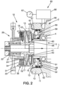
Figure 2 is a partial view in section along line II-II of detail referenced A onFigure 1 of the pneumatic clutch ofFigure 1 to which a wear measurement device is connected, the pneumatic clutch having an interface member movably mounted on a second shaft member and urged towards an engaged position by a biasing member so that the second shaft member is caused to rotate by a first shaft member linked to the engine of the vehicle, the pneumatic clutch further having an actuation device which, upon actuation by injection of compressed air as pressurized fluid, acts on the biasing member to move the interface member towards a disengaged position to stop the second shaft member from being driven, -
Figure 3 is an enlarged view of the detail referenced B onFigure 2 illustrating a contact part of the actuation device in a rest position in which it is spaced apart from the biasing member so as to let the biasing member urging the interface member towards the engaged position,Figure 3 also illustrates a gap between the contact part of the actuation device and the biasing member when wear of the pneumatic clutch has (a) a value W1 corresponding to situations where no or almost no wear has occurred, (b) a value W2 corresponding to situations where wear is intermediate and (c) a value W3 corresponding to situations where wear is maximum, -
Figure 4 is an enlarged view of the detail referenced B onFigure 2 illustrating the contact part of the actuation device in an active position in which it is in contact with the biasing member so as to let the interface member move towards the disengaged position, -
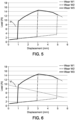
Figure 5 is a graph illustrating evolution of load of the contact part of the actuation device on the biasing member as a function of displacement of the contact part for the different values W1, W2, W3 of wear in an embodiment in which the gap is measured based on a volume of compressed air injected until an input pressure of compressed air is reached as the injection parameter, -
Figure 6 is a graph illustrating evolution of load of the contact part of the actuation device on the biasing member as a function of displacement of the contact part for the different values W1, W2, W3 of wear in an embodiment in which the gap is measured based on a pressure of compressed that is reached after an input volume of compressed air has been injected as the injection parameter. - On the Figures, the same reference numbers refer to the same or similar elements.
-
Figure 1 shows an assembly of a system including a clutch according to an embodiment of the invention. - In the represented embodiment, although not limited thereto, the assembly is part of a pneumatic system of a vehicle, especially a large vehicle such as a truck or a bus, comprising one or several pneumatic equipments, such as a pneumatic braking system, operating with compressed air.
- On
Figures 1 and2 , the assembly comprises anair compressor 1 intended to supply the pneumatic equipments of the pneumatic system with compressed air. Theair compressor 1 comprises: - a
casing 2 presenting a longitudinal axis L, - a
shaft 3 extending along the longitudinal axis L and rotatably mounted about the longitudinal axis L, for example throughball bearings 4, and - a transmission mechanism, not shown, configured to produce compressed air as the
shaft 3 rotates about the longitudinal axis L. - The
shaft 3 is caused to rotate thanks to an engine of the vehicle further driving wheels or other contact members with which the vehicle may move on a ground surface. To that end, theair compressor 1 may be connected to the engine of the vehicle. Nevertheless, in order to save fuel, it should be possible to disconnect theair compressor 1 from the engine when pressure in the pneumatic system is sufficient and it is no longer necessary to supply compressed air. To that end, theair compressor 1 includes a clutch 10 though which it is connected to the engine. - The clutch 10 comprises a
first shaft member 20 configured to rotate about the longitudinal axis L with respect to thecasing 2. More specifically, thefirst shaft member 20 comprises ahub 21 tubular along the longitudinal axis L and rotatably mounted on a portion of theshaft 3 of theair compressor 1 protruding from thecasing 2, for example throughroller bearings 22. From an end of thehub 21 opposite theair compressor 1, agear 23 extends radially with respect to the longitudinal axis L, and extends away from the longitudinal axis L. Thegear 23 is configured to be linked, through a transmission arrangement not shown, to the engine of the vehicle. Thefirst shaft member 20 is hence driven in rotation as the engine of the vehicle rotates. At an end of thehub 21 opposite thegear 23 and then close to theair compressor 1, one orseveral friction disks 24, three onFigure 2 , extend radially with respect to the longitudinal axis L, away from the longitudinal axis L. - The clutch 10 also comprises a
second shaft member 16 including an annular hub 17 fitted on theshaft 3 of theair compressor 1. Aflange 18 extends radially from the hub 17 of thesecond shaft member 16 and extends away from the longitudinal axis L. - The clutch 10 comprises an
interface member 30 having anannular portion 31 extending axially with respect to the longitudinal axis L between opposite ends, and atransverse portion 32 extending radially with respect to the longitudinal axis L, towards the longitudinal axis L at one of the ends of theannular portion 31. On an inner surface, directed towards the longitudinal axis L, theannular portion 31 is provided with one or several, four onFigure 2 ,friction disks 34 extending radially with respect to the longitudinal axis L, towards the longitudinal axis L. Theannular portion 31 of theinterface member 30 is mounted on theflange 18 of thesecond shaft member 16 in any appropriate manner, for example through flutes cooperating with corresponding flutes on theflange 18 of thesecond shaft member 16, so as to be moveable in translation along the longitudinal axis L while being fixed in rotation with respect to thesecond shaft member 16, thetransverse portion 32 being directed towards theair compressor 1 and thefriction disks 34 of theinterface member 30 facing thefriction disks 24 of thefirst shaft member 20. - A biasing
member 40, in the form of anannular cup spring 41, is provided to urge theinterface member 30 towards an engaged position in which itsfriction disks 34 are in contact with thefriction disks 24 of thefirst shaft member 20. In such engaged position, rotation of thefirst shaft member 20 imparted by the engine of the vehicle is transmitted to thesecond shaft member 16 through thefriction disks interface member 30. More particularly, thecup spring 41 has an inclined wall from an outercircular base 42 to an innercircular summit 43. Thesummit 43 is fitted on the hub 17 of thesecond shaft member 16 at a distance from theflange 18, and thebase 42 rests against theflange 18. A portion of thecup spring 41 between the base 42 and thesummit 43 rests against anannular protrusion 35 formed on thetransverse portion 32 of theinterface member 30 so as to space apart thetransverse portion 32 of theinterface member 30 from theflange 18 and to put thefrictions disks 34 of theinterface member 30 in contact with thefriction disks 24 of thefirst shaft member 20. - In the represented embodiment, the
first shaft member 20 is configured to be linked to the engine while thesecond shaft member 16 is configured to be driven a rotation by thefirst shaft member 20 through theinterface member 30 and the biasingmember 40. Thefirst shaft member 20 acts as a driving shaft while thesecond shaft member 16 acts as a driven shaft. The invention is however not limited to such arrangement. In another embodiment, thesecond shaft member 16 could act as a driving shaft while thefirst shaft member 20 could act as a driven shaft thanks to appropriate configuration and arrangement of the first 20 and second 16 shaft members as well as of theinterface member 30 and the biasingmember 40. - In order to enable the
interface member 30 to be moved to a disengaged position in which itsfriction disks 34 are spaced apart from thefriction disks 24 of thefirst shaft member 16 to thereby disconnect thefirst shaft member 16 from thesecond shaft member 20, the clutch 10 comprises anactuation device 50. - The
actuation device 50 comprises ahousing 11, apiston part 51 slidably mounted within thehousing 11 and acontact part 57. Thehousing 11 and thepiston part 51 define apressure chamber 55 configured to be reversibly filled with a pressurized fluid so as to reciprocate thepiston part 51 within thehousing 11. Thecontact part 57 is linked to thepiston part 51 so as to be moveable in translation along the longitudinal axis L. - In the represented embodiment, the
actuation device 50 partly integrated in thecasing 2 of theair compressor 1. - More specifically, the
casing 2 includes awall 12 that is annular around the longitudinal axis L. The wall has aninner contact surface 13 cylindrical along the longitudinal axis L and provided with aring 14 around the longitudinal axis L. Thering 14 has a generallyU-shaped groove 15 opened opposite theair conditioner 1. Thewall 12 forms thehousing 11 of theactuation device 50. - The
piston part 51 of theactuation device 50 is slidably mounted on theinner contact surface 13 of thewall 12 so as to be moveable in translation along the longitudinal axis L. Advantageously, thepiston part 51 is provided with sealingjoints 52 and arranged within thegroove 15 of thering 14 of thecasing 2. Thepiston part 51 and theinner contact surface 13 of thewall 12 define thepressure chamber 55. Anaccess port 56 is arranged in thecasing 2 and opens into thepressure chamber 55. - In the represented embodiment, the
contact part 57 is advantageously directly fitted on thesecond shaft member 16 and directly linked to thepiston part 51. In particular, thecontact part 57 has anannular skirt 58 fitted on the hub 17 of thesecond shaft member 16. To enable thecontact part 57 to rotate along with thesecond shaft member 16 with respect to thepiston part 51 while enabling a translation of thepiston part 51 to be transmitted to thecontact part 57, aroller bearing 59 is provided betweenpiston 51 and contact 57 parts. - Although disclosed in relation with an
actuation device 50 partly integrated within thecasing 2 of theair compressor 1, the invention is not limited thereto. In other embodiments, the actuation device could be any otherwise configured. For example, the actuation device could be separate from thecasing 2 of theair compressor 1. Theactuation device 50 could then have a housing apart from thecasing 2 of theair compressor 1, in which the piston part may reciprocate. The contact part could be linked to the piston part in any appropriate manner, form example through one or several articulated links, to be movable along the longitudinal direction L. - On
Figure 3 , as thepressure chamber 55 is empty, thecontact part 57 is in a rest position in which a free end of theskirt 58 is spaced apart from thesummit 43 of thecup spring 41. In this position, thecup spring 41 freely exerts a biasing force to urge theinterface member 30 towards the engaged position thanks to the contacts with theflange 18 of thefirst shaft member 16 and theprotrusion 35 of thetransverse portion 32 of theinterface member 30 as explained above. - A
return member 60 is provided to urge the contact part of the actuation device towards the rest position. In the represented embodiment, thereturn member 60 is in the form of anannular cup spring 61 having an inclined wall from an outer circular base to an inner circular summit. The summit is fitted on theskirt 58 of thecontact part 57 and the base rests thetransverse portion 32 of theinterface member 30. Thereturn member 60 exerts a biasing force in a direction opposite that of thecup spring 41 of the biasingmember 40. The biasing force of thereturn member 60 has then a lower amplitude than that of the biasingmember 40 to avoid thereturn member 60 to counteract against the biasingmember 40 and ensure theinterface member 30 remains in the engaged portion under the effect of the biasingmember 40 when both biasing 40 and return 60 members acts on theinterface member 30. - In the rest position, a gap G exists between the free end of the
skirt 58 of thecontact part 57 and thesummit 43 of thecup spring 41. During the vehicle life time, wear of thefriction disks Figure 3 illustrates the gap G when wear W of the clutch 10 has (a) a value W1 corresponding to a situation where no or almost no wear has occurred, (b) a value W2 corresponding to a situation where wear W is intermediate and (c) a value W3 corresponding to a situation where wear W is maximum. - In the represented embodiment, the gap G decreases as wear W increases. As a purely illustrative and non-limiting example, a design of the clutch 10 may be such that:
- when no wear W as occurred, the value W1 equals to 0 mm, the gap G measures 5 mm,
- when the wear W is intermediate, and especially medium, the value W2 equals to 0.6 mm, the gap G measures 3 mm, the
summit 43 of thecup spring 41 having been displaced of 2 mm, - when the wear W is maximum, the value W3 equals to 1.2 mm, the gap G measures 1 mm, the
summit 43 of thecup spring 41 having been displaced of 4 mm. - It derives from the above that according to the particular design, a relation between the wear W and a displacement D of the
summit 43 of thecup spring 41 is W = D/3.33 and hence, a relation between the wear W and the gap G is W = (G0-G)/3.33 where G0 in the initial gap when no wear has occurred. - Depending on the design, wear W of the clutch 10 can be determined based on the gap G through the relation W = (G0-G)/k where k calculated based on a ratio of a total height of the biasing
member 40, measured along the longitudinal direction L, and a height from thebase 42 of the biasingmember 40 to theprotrusion 35 of thetransverse portion 32 of theinterface member 30. Alternatively, the coefficient k may be determined empirically on a test bench. - As apparent from the above and as illustrated on
Figure 4 , injection of pressurized fluid within thepressure chamber 55 through theaccess port 56 may cause thecontact part 57 of theactuation device 50 to move towards an active position in which it is in contact with thesummit 43 of thecup spring 41 to remove the contact of thecup spring 41 with theprotrusion 35 of thetransverse portion 32 of theinterface member 30. The biasing force of thecup spring 41 no longer exerts on theinterface member 30 which may move towards the disengaged position under the effect of thereturn member 60. In the disengaged position of theinterface member 30, itsfriction disks 34 are spaced apart from thefriction disks 24 of thefirst shaft member 16 thereby releasing thesecond shaft member 16 from thefirst shaft member 20. - In the represented embodiment, the clutch 10 is preferably a pneumatic clutch in which the pressurized fluid is compressed air. To ensure disconnection of the
air compressor 1 from the engine when pressure in the pneumatic system is sufficient, a conduit may be removably connected to theaccess port 56 for supplying thepressure chamber 55 of the clutch 10 with compressed air from an outlet port of theair compressor 1. - In order to measure wear of the clutch 10, for example during maintenance of the vehicle, a
wear measurement device 65 is provided. - The
wear measurement device 65 comprises a source ofpressurized fluid 66, and especially of compressed air, configured to be connected in a removable manner to theaccess port 56 and to inject pressurized fluid within thepressure chamber 55. Thewear measurement device 65 may also comprise a pumping member. The pumping member may be the same device as the source ofpressurized fluid 66 but operated in an inverted manner or a separate device. - The
wear measurement device 65 also comprises: - a
sensor arrangement 67 configured to measure at least one injection parameter chosen between a pressure and a volume of pressurized fluid while pressurized fluid is injected, and - a control member suitable for determining the gap between the
contact part 57 of theactuation device 50 and the biasingmember 40 based on the injection parameter. - The injection parameter is related to the gap G between the
contact part 57 of theactuation device 50 and the biasingmember 40. Such relation may be established empirically, once on a test bench, for each design ofclutch 10. Experiments can then be carried out to associate each value of the injection parameter to a value of the gap G. Results of these experiments can be stored in the form of a table, a curve, a transfer function and similar on a sheet or an electronic memory of a control unit, which sheet or electronic memory of a control unit will serve as control member. - A method for measuring wear of the clutch 10 implementing the wear measurement device is now disclosed in relation to
Figures 5 and 6 . - Initially, the conduit between the
access port 56 and the outlet of theair compressor 1 is disconnected and the pumping member of thewear measurement device 65 is connected to theaccess port 56 to apply vacuum to thechamber 56. In doing so, thepressure chamber 55 is emptied and thecontact part 57 of theactuation device 50 is positioned in the rest position. - The pumping member is then removed and the source of
pressurized fluid 66 is connected to theaccess port 56. Alternatively, the device operating either as pumping member or source ofpressurized fluid 66 is operated in the inverted manner. Thepressure chamber 55 is then filled with pressurized fluid so as to put thecontact part 57 of theactuation device 50 in contact with thecup spring 41 of the biasingmember 40 as it is moved towards the active position. - While pressurized fluid is injected, the injection parameter is measured and the gap G between the
contact part 57 of theactuation device 50 and thecup spring 41 of the biasingmember 40 is determined based on the injection parameter. - In an embodiment shown on
figure 5 , thesensor arrangement 67 is configured to measure the volume of pressurized fluid injected in thepressure chamber 55 of theactuation device 50 as the injection parameter until an input pressure Pi of pressurized fluid is reached. The input pressure Pi is chosen to be representative of a contact situation where thecontact part 57 of theactuation device 50 is in contact with the biasingmember 40. In particular, the input pressure Pi may be greater than or equal to a maximum pressure on a full range of wear to have thecontact part 57 of theactuation device 50 and the biasingmember 40 in contact, and lower than or equal to a minimum pressure on the full range of wear to have theinterface member 30 in the disengaged position. The full range of wear gathers wears fromnew friction disks 34 of theinterface member 30 and of thefirst shaft member 20 having no wear to withfriction disks 34 of theinterface member 30 and thefirst shaft member 20 to be replaced having a maximum wear. - As illustrated on
Figure 5 , the above provisions as regards input pressure Pi ensure, that whichever the wear is, namely W1, W2 or W3, as the input pressure is reached, load of thecontact part 57 of theactuation device 50 as a function of the displacement of thecontact part 57 is a raising portion representative of the situation where thecontact part 57 is acting on the biasingmember 40. - Depending on the value of the volume of pressurized fluid injected within the
pressure chamber 55 before the input pressure Pi is reached, the value of the gap G between thecontact part 57 of theactuation device 50 and the biasingmember 40 and, in turn, wear W of the clutch 10 can be determined thanks to the control member of thewear measurement device 65. - In an alternative embodiment on
Figure 6 , thesensor arrangement 67 is configured to measure the pressure of pressurized fluid injected in thepressure chamber 55 of theactuation device 50 that is reached after an input volume Vi of pressurized fluid has been injected as the injection parameter. The input volume Vi is chosen to be representative of a contact situation where thecontact part 57 of theactuation device 50 is in contact with the biasingmember 40. In particular, the input volume Vi is greater than or equal to a maximum volume on a full range of wear to have thecontact part 57 of theactuation device 50 and the biasingmember 40 in contact, and lower than or equal to a minimum volume on the full range of wear to have theinterface member 30 in the disengaged position. - Here again, as illustrated on
Figure 6 , the above provisions as regards input volume Vi ensure, that whichever the wear is, namely W1, W2 or W3, the input volume Vi is injected to ensure that load of thecontact part 57 of theactuation device 50 as a function of the displacement of thecontact part 57 is the raising portion representative of the situation where thecontact part 57 is acting on the biasingmember 40. - Depending on the value of the pressure of pressurized fluid within the
pressure chamber 55 after the input volume has been injected, the value for the gap G between thecontact part 57 of theactuation device 50 and the biasingmember 40 and, in turn, wear W of the clutch 10 can be determined thanks to the control member of thewear measurement device 65. - Such method finds advantageous application in maintenance of the vehicle and, more particularly, of the pneumatic system of the vehicle since it enables the clutch 10 to be replaced if a critical gap between the actuator 50 and the biasing
member 40 representative of a critical wear of thefriction disks interface member 30 and thefirst shaft member 20 is determined. - The invention has been disclosed in relation with a
pneumatic clutch 10 of an air compressor of apneumatic system 1. The invention applies to any system implementing a clutch operating with any other pressurized fluid to selectively couple and decouple first and second shaft members.
Claims (18)
- Method for measuring wear of a clutch (10), the clutch (10) comprising:- a casing (2) presenting a longitudinal axis (L),- a first shaft member (20) configured to rotate about the longitudinal axis (L) with respect to the casing (2), the first shaft member (20) including at least one friction disk (24) extending radially with respect to the longitudinal axis (L),- a second shaft member (16) configured to rotate about the longitudinal axis (L) with respect to the casing (2),- an interface member (30) mounted on the second shaft member (16) so as to be moveable in translation along the longitudinal axis (L) while being fixed in rotation with respect to the second shaft member (16), the interface member (30) including at least one friction disk (34) extending radially with respect to the longitudinal axis (L) so as to face the friction disk (24) of the first shaft member (20), the interface member (30) being moveable between an engaged position in which the friction disk (34) of said interface member (30) is in contact with the friction disk (24) of the first shaft member (20), and a disengaged position in which the friction disk (34) of said interface member (30) is spaced apart from the friction disk (24) of the first shaft member (20),- a biasing member (40) urging the interface member (30) towards the engaged position,- an actuation device (50) comprising a housing (11), a piston part (51) slidably mounted within the housing (11) and a contact part (57), the housing (11) and the piston part (51) defining a pressure chamber (55) configured to be reversibly filled with pressurized fluid so as to reciprocate the piston part (51) within the housing (11), the contact part (57) being linked to the piston part (51) so as to be moveable in translation along the longitudinal axis (L) between:a rest position in which said contact part (57) is spaced apart from the biasing member (40) when the pressure chamber (55) is empty, a gap (G) existing between the contact part (57) and the biasing member (40), andan active position in which the contact part (57) is in contact with the biasing member (40) when the pressure chamber (55) is filled with pressurized fluid, so as to let the interface member (30) move towards the disengaged position,wherein the method comprises:- from the rest position of the contact part (57) of the actuation device (50), injecting pressurized fluid within the pressure chamber (55) of the actuation device (50) so as to put the contact part (57) in contact with the biasing member (40),- while pressurized fluid is injected, measuring at least one injection parameter chosen between a pressure and a volume of pressurized fluid, the injection parameter being related to the gap (G) between the contact part (57) and the biasing member (40),- determining the gap (G) between the contact part (57) and the biasing member (40) based on the injection parameter, the gap (G) being representative of wear (W) of the friction disks (24, 34) of the interface member (30) and the first shaft member (20) characterised in that the method further comprises, before injecting pressurized fluid within the pressure chamber (55) of the actuation device (50), checking that the contact part (57) of the actuation device (50) is in the rest position, vacuum being applied to the pressure chamber (55) of the actuation device (50).
- Method according to claim 1, wherein pressurized fluid is injected until an input pressure (Pi) is reached, the input pressure (Pi) being representative of a contact situation where the contact part (57) of the actuation device (50) is in contact with the biasing member (40),
and wherein the volume of pressurized fluid injected in the pressure chamber (55) of the actuation device (50) is measured as the injection parameter until the input pressure (Pi) is reached. - Method according to claim 2, wherein the input pressure (Pi) is greater than or equal to a maximum pressure on a full range of wear to have the contact part (57) of the actuation device (50) and the biasing member (40) in contact, and lower than or equal to a minimum pressure on the full range of wear to have the interface member (30) in the disengaged position.
- Method according to claim 1, wherein an input volume (Vi) of pressurized fluid is injected, the input volume (Vi) being representative of a contact situation where the contact part (57) of the actuation device (50) is in contact with the biasing member (40),
and wherein the pressure of pressurized fluid injected in the pressure chamber (55) of the actuation device (50) that is reached after the input volume (Vi) has been injected is measured as the injection parameter. - Method according to claim 4, wherein the input volume (Vi) is greater than or equal to a maximum volume on a full range of wear to have the contact part (57) of the actuation device (50) and the biasing member (40) in contact, and lower than or equal to a minimum volume on the full range of wear to have the interface member (30) in the disengaged position.
- Method according to any of claims 1 to 5, wherein the casing (2) includes:- a wall (12) around the longitudinal axis (L), the wall (12) presenting an inner contact surface (13) cylindrical along the longitudinal axis (L), the wall forming the housing (11) of the actuation device (50) and the piston part (51) of the actuation device (50) being slidably mounted on the inner contact surface (13),- an access port (56) arranged in the casing (2) and opening into the pressure chamber (55) of the actuation device (50), the access port (56) being configured to enable the pressure chamber (55) to be filled with pressurized fluid so as to place the contact part (57) of the actuation device (50) in the active position and to be emptied so as to place the contact part (57) of the actuation device (50) in the rest position.
- Method according to claim 1 to 6, wherein the clutch is the pneumatic clutch (10) of an air compressor (1) of a pneumatic system of a vehicle, the first shaft member (20) being linked to an engine of the vehicle and the second shaft member (16) being mounted on the shaft (3) of the air compressor (1), the air compressor (1) supplying at least one pneumatic equipment of the pneumatic system of the vehicle with compressed air as the shaft (3) rotates.
- Method according to claim 7, wherein the air compressor (1) comprises a conduit removably connected to the housing (11) of the actuation device (50) for supplying the pressure chamber (55) with compressed air from an outlet port of the air compressor (1),
and wherein the method comprises, before injecting compressed air within the pressure chamber (55) of the actuation device (50), disconnecting the conduit from the housing (11) and connecting a source of compressed air (66) to the housing (11). - Maintenance method of a system including a clutch (10), the maintenance method comprising:- implementing the method according to any of claims 1 to 8,- replacing the clutch (10) if a critical gap between the contact (57) part of the actuation device (50) and the biasing member (40) representative of a critical wear of the friction disks (24, 34) of the interface member (30) and the first shaft member (20) is determined.
- Assembly comprising a clutch (10) and a wear measurement device (65) for measuring wear of the clutch (10),
wherein the clutch (10) comprises:- a casing (2) presenting a longitudinal axis (L),- a first shaft member (20) configured to rotate about the longitudinal axis (L) with respect to the casing (2), the first shaft member (20) including at least one friction disk (24) extending radially with respect to the longitudinal axis (L),- a second shaft member (16) configured to rotate about the longitudinal axis (L) with respect to the casing (2),- an interface member (30) mounted on the second shaft member (16) so as to be moveable in translation along the longitudinal axis (L) while being fixed in rotation with respect to the second shaft member (16), the interface member (30) including at least one friction disk (34) extending radially with respect to the longitudinal axis (L) so as to face the friction disk (24) of the first shaft member (20), the interface member (30) being moveable between an engaged position in which the friction disk (34) of said interface member (30) is in contact with the friction disk (24) of the first shaft member (20), and a disengaged position in which the friction disk (34) of said interface member (30) is spaced apart from the friction disk (24) of the first shaft member (20),- a biasing member (40) urging the interface member (30) towards the engaged position,- an actuation device (50) comprising a housing (11), a piston part (51) slidably mounted within the housing (11) and a contact part (57), the housing (11) and the piston part (51) defining a pressure chamber (55) configured to be reversibly filled with pressurized fluid so as to reciprocate the piston part (51) within the housing (11), the contact part (57) being linked to the piston part (51) so as to be moveable in translation along the longitudinal axis (L) between:a rest position in which said contact part (57) is spaced apart from the biasing member (40) when the pressure chamber (55) is empty, a gap (G) existing between the contact part (57) and the biasing member (40), andan active position in which the contact part (57) is in contact with the biasing member (40) when the pressure chamber (55) is filled with pressurized fluid, so as to let the interface member (30) move towards the disengaged position, andwherein the wear measurement device (65) comprises:- a source of pressurized fluid (66) configured to inject pressurized fluid within the pressure chamber (55) so as to put the contact part (57) of the actuation device (50) in contact with the biasing member (40),- a sensor arrangement (67) configured to measure at least one injection parameter chosen between a pressure and a volume of pressurized fluid while pressurized fluid is injected, the injection parameter being related to the gap (G) between the contact part (57) of the actuation device (50) and the biasing member (40),- a control member suitable for determining the gap (G) between the contact part (57) of the actuation device (50) and the biasing member (40) based on the injection parameter, the gap (G) being representative of wear of the friction disks (24, 34) of the interface member (30) and the first shaft member (20)wherein the wear measurement device (65) is configured to check that the contact part (57) of the actuation device (50) is in the rest position before injecting pressurized fluid within the pressure chamber (55), the wear measurement device (65) further comprising a pumping member configured to apply vacuum to the pressure chamber (55) before injecting pressurized fluid within the pressure chamber (55). - Assembly according to claim 10, wherein the sensor arrangement (67) is configured to measure the volume of pressurized fluid injected in the pressure chamber (55) of the actuation device (50) as the injection parameter until an input pressure (Pi) of pressurized fluid is reached, the input pressure (Pi) being representative of a contact situation where the contact part (57) of the actuation device (50) is in contact with the biasing member (40),
and wherein the control member of the wear measurement device (65) is configured to associate a value of the volume of pressurized fluid to a value for the gap (G) between the contact part (57) of the actuation device (50) and the biasing member (40). - Assembly according to claim 11, wherein the input pressure (Pi) is greater than or equal to a maximum pressure on a full range of wear to have the contact part (57) of the actuation device (50) and the biasing member (40) in contact, and lower than or equal to a minimum pressure on the full range of wear to have the interface member (30) in the disengaged position.
- Assembly according to claim 10, wherein the sensor arrangement (67) is configured to measure the pressure of pressurized fluid injected in the pressure chamber (55) of the actuation device (50) that is reached after an input volume (Vi) of pressurized fluid has been injected as the injection parameter, the input volume (Vi) being representative of a contact situation where the contact part (57) of the actuation device (50) is in contact with the biasing member (40),
and wherein the control member of the wear measurement device (65) is configured to associate a value of the pressure of pressurized fluid to a value for the gap (G) between the contact part (57) of the actuation device (50) and the biasing member (40). - Assembly according to claim 13, wherein the input volume (Vi) is greater than or equal to a maximum volume on a full range of wear to have the contact part (57) of the actuation device (50) and the biasing member (40) in contact, and lower than or equal to a minimum volume on the full range of wear to have the interface member (30) in the disengaged position.
- Assembly according to any of claims 10 to 14, wherein the casing (2) includes:- a wall (12) around the longitudinal axis (L), the wall (12) presenting an inner contact surface (13) cylindrical along the longitudinal axis (L), the wall forming the housing (11) of the actuation device (50) and the piston part (51) of the actuation device (50) being slidably mounted on the inner contact surface (13),- an access port (56) arranged in the casing (2) and opening into the pressure chamber (55) of the actuation device (50), the access port (56) being configured to enable the pressure chamber (55) to be filled with pressurized fluid so as to place the contact part (57) of the actuation device (50) in the active position and to be emptied so as to place the contact part (57) of the actuation device (50) in the rest position.
- Assembly according to any of claims 10 to 15, further comprising an air compressor (1) of a pneumatic system of a vehicle, and wherein the clutch is the pneumatic clutch (10) of the air compressor (1), the first shaft member (20) being configured to be linked to an engine of the vehicle and the second shaft member (16) being mounted on the shaft (3) of the air compressor (1), the air compressor (1) supplying at least one pneumatic equipment of the pneumatic system of the vehicle with compressed air as the shaft (3) rotates.
- Assembly according to claim 16, wherein the air compressor (1) comprises a conduit removably connected to the housing (11) of the actuation device (50) for supplying the pressure chamber (55) with compressed air from an outlet port of the air compressor (1).
- Vehicle comprising an assembly according to any of claims 10 to 17.
Applications Claiming Priority (1)
| Application Number | Priority Date | Filing Date | Title |
|---|---|---|---|
| PCT/EP2018/070852 WO2020025125A1 (en) | 2018-08-01 | 2018-08-01 | Method for measuring wear of a clutch and related maintenance method, assembly comprising a clutch and a wear measurement device, and vehicle |
Publications (3)
| Publication Number | Publication Date |
|---|---|
| EP3830441A1 EP3830441A1 (en) | 2021-06-09 |
| EP3830441B1 true EP3830441B1 (en) | 2025-07-02 |
| EP3830441C0 EP3830441C0 (en) | 2025-07-02 |
Family
ID=63108556
Family Applications (1)
| Application Number | Title | Priority Date | Filing Date |
|---|---|---|---|
| EP18750157.2A Active EP3830441B1 (en) | 2018-08-01 | 2018-08-01 | Method for measuring wear of a clutch and related maintenance method, assembly comprising a clutch and a wear measurement device, and vehicle |
Country Status (4)
| Country | Link |
|---|---|
| US (1) | US11320008B2 (en) |
| EP (1) | EP3830441B1 (en) |
| CN (1) | CN112534150B (en) |
| WO (1) | WO2020025125A1 (en) |
Families Citing this family (2)
| Publication number | Priority date | Publication date | Assignee | Title |
|---|---|---|---|---|
| CN113532876B (en) * | 2021-07-13 | 2024-05-17 | 潍柴动力股份有限公司 | Method and device for calculating clutch wear, storage medium and electronic equipment |
| CN116538210B (en) * | 2023-05-10 | 2025-09-19 | 潍柴动力股份有限公司 | Pneumatic clutch control method and device, vehicle and storage medium |
Family Cites Families (11)
| Publication number | Priority date | Publication date | Assignee | Title |
|---|---|---|---|---|
| US3286803A (en) * | 1964-05-28 | 1966-11-22 | Borg Warner | Adjustment mechanism for clutch linkage |
| JPS57129148A (en) * | 1981-02-02 | 1982-08-11 | Hitachi Ltd | Detector for abrasion of friction disk of clutch motor |
| US5377803A (en) * | 1992-05-06 | 1995-01-03 | Fichtel & Sachs Ag | Pressure plate arrangement for a motor vehicle friction clutch |
| JPH09280348A (en) * | 1996-04-10 | 1997-10-28 | Komatsu Ltd | Method for detecting wear of clutch of transmission and detecting device therefor |
| JPH1193973A (en) * | 1997-09-24 | 1999-04-06 | Mitsubishi Motors Corp | Vehicle clutch wear detector |
| DE102008043492A1 (en) | 2008-11-05 | 2010-05-06 | Zf Friedrichshafen Ag | Method and arrangement for determining the state of wear of a clutch |
| DE102010034810A1 (en) * | 2009-09-24 | 2011-03-31 | Schaeffler Technologies Gmbh & Co. Kg | Friction clutch with transport-secured adjuster |
| US8346451B2 (en) * | 2010-02-23 | 2013-01-01 | GM Global Technology Operations LLC | Realtime estimation of clutch piston position |
| CN104812640B (en) * | 2012-08-23 | 2017-06-09 | 皮尔伯格泵技术有限责任公司 | Aerobraking servicing unit |
| US10233982B2 (en) * | 2014-11-19 | 2019-03-19 | Gkn Automotive Ltd. | Operating a clutch in a motor vehicle |
| KR102259654B1 (en) * | 2016-05-03 | 2021-06-02 | 엘지전자 주식회사 | Linear compressor |
-
2018
- 2018-08-01 EP EP18750157.2A patent/EP3830441B1/en active Active
- 2018-08-01 US US17/264,429 patent/US11320008B2/en active Active
- 2018-08-01 WO PCT/EP2018/070852 patent/WO2020025125A1/en not_active Ceased
- 2018-08-01 CN CN201880095985.7A patent/CN112534150B/en active Active
Also Published As
| Publication number | Publication date |
|---|---|
| CN112534150A (en) | 2021-03-19 |
| US11320008B2 (en) | 2022-05-03 |
| EP3830441A1 (en) | 2021-06-09 |
| WO2020025125A1 (en) | 2020-02-06 |
| EP3830441C0 (en) | 2025-07-02 |
| CN112534150B (en) | 2022-07-29 |
| US20210310527A1 (en) | 2021-10-07 |
Similar Documents
| Publication | Publication Date | Title |
|---|---|---|
| KR101524327B1 (en) | Slave cylinder and release system | |
| US7604106B2 (en) | Clutch system | |
| US8738256B2 (en) | Automatic calibration of the torque transfer touch point in an electrically actuated clutch in a hybrid vehicle | |
| US20110259699A1 (en) | Clutch System and Methods | |
| US11320008B2 (en) | Method for measuring wear of a clutch and related maintenance method, assembly comprising a clutch and a wear measurement device, and vehicle | |
| CA1219537A (en) | Drive mechanism | |
| US9416827B1 (en) | Clutch assembly with dual actuation piston | |
| CN104350310B (en) | wet dual clutch transmission | |
| US7104382B2 (en) | Clutch system | |
| US5207306A (en) | Device for operating clutch of vehicle | |
| US9284993B1 (en) | Clutch assembly with dual actuation piston | |
| US8807290B2 (en) | Brake assembly having wear and failure indicator | |
| CN115808308B (en) | Roller bearing and guide pulley coating performance test device | |
| US10821827B1 (en) | Truck clutch conversion kit | |
| US8839933B1 (en) | PTO clutch assembly | |
| CN111765235A (en) | Hydraulic transmission | |
| US12449034B2 (en) | Tracked combat vehicle with integrated motor brake having clutch sensors | |
| US10344809B2 (en) | Clutch control | |
| US10151356B2 (en) | Hydraulic engagement device | |
| CN100535467C (en) | Actuator for vehicle clutch | |
| CN216009443U (en) | Hydraulically controlled limited slip differential | |
| US11149800B1 (en) | Clutch lubrication system | |
| CN113738845A (en) | Hydraulically controlled limited slip differential | |
| CN108006113B (en) | A radial friction clutch with a plunger cylinder pushing a tapered guide rail | |
| CN104214240A (en) | Clutch branch pump suitable for manual transmission automobile |
Legal Events
| Date | Code | Title | Description |
|---|---|---|---|
| STAA | Information on the status of an ep patent application or granted ep patent |
Free format text: STATUS: UNKNOWN |
|
| STAA | Information on the status of an ep patent application or granted ep patent |
Free format text: STATUS: THE INTERNATIONAL PUBLICATION HAS BEEN MADE |
|
| STAA | Information on the status of an ep patent application or granted ep patent |
Free format text: STATUS: REQUEST FOR EXAMINATION WAS MADE |
|
| PUAI | Public reference made under article 153(3) epc to a published international application that has entered the european phase |
Free format text: ORIGINAL CODE: 0009012 |
|
| 17P | Request for examination filed |
Effective date: 20210222 |
|
| AK | Designated contracting states |
Kind code of ref document: A1 Designated state(s): AL AT BE BG CH CY CZ DE DK EE ES FI FR GB GR HR HU IE IS IT LI LT LU LV MC MK MT NL NO PL PT RO RS SE SI SK SM TR |
|
| DAV | Request for validation of the european patent (deleted) | ||
| DAX | Request for extension of the european patent (deleted) | ||
| STAA | Information on the status of an ep patent application or granted ep patent |
Free format text: STATUS: EXAMINATION IS IN PROGRESS |
|
| 17Q | First examination report despatched |
Effective date: 20230829 |
|
| GRAP | Despatch of communication of intention to grant a patent |
Free format text: ORIGINAL CODE: EPIDOSNIGR1 |
|
| STAA | Information on the status of an ep patent application or granted ep patent |
Free format text: STATUS: GRANT OF PATENT IS INTENDED |
|
| INTG | Intention to grant announced |
Effective date: 20250404 |
|
| GRAS | Grant fee paid |
Free format text: ORIGINAL CODE: EPIDOSNIGR3 |
|
| GRAA | (expected) grant |
Free format text: ORIGINAL CODE: 0009210 |
|
| STAA | Information on the status of an ep patent application or granted ep patent |
Free format text: STATUS: THE PATENT HAS BEEN GRANTED |
|
| AK | Designated contracting states |
Kind code of ref document: B1 Designated state(s): AL AT BE BG CH CY CZ DE DK EE ES FI FR GB GR HR HU IE IS IT LI LT LU LV MC MK MT NL NO PL PT RO RS SE SI SK SM TR |
|
| REG | Reference to a national code |
Ref country code: GB Ref legal event code: FG4D |
|
| REG | Reference to a national code |
Ref country code: CH Ref legal event code: EP |
|
| REG | Reference to a national code |
Ref country code: DE Ref legal event code: R096 Ref document number: 602018083198 Country of ref document: DE |
|
| REG | Reference to a national code |
Ref country code: IE Ref legal event code: FG4D |
|
| U01 | Request for unitary effect filed |
Effective date: 20250801 |
|
| U07 | Unitary effect registered |
Designated state(s): AT BE BG DE DK EE FI FR IT LT LU LV MT NL PT RO SE SI Effective date: 20250818 |
|
| U20 | Renewal fee for the european patent with unitary effect paid |
Year of fee payment: 8 Effective date: 20250825 |
|
| PG25 | Lapsed in a contracting state [announced via postgrant information from national office to epo] |
Ref country code: IS Free format text: LAPSE BECAUSE OF FAILURE TO SUBMIT A TRANSLATION OF THE DESCRIPTION OR TO PAY THE FEE WITHIN THE PRESCRIBED TIME-LIMIT Effective date: 20251102 |
|
| PG25 | Lapsed in a contracting state [announced via postgrant information from national office to epo] |
Ref country code: NO Free format text: LAPSE BECAUSE OF FAILURE TO SUBMIT A TRANSLATION OF THE DESCRIPTION OR TO PAY THE FEE WITHIN THE PRESCRIBED TIME-LIMIT Effective date: 20251002 |
|
| PG25 | Lapsed in a contracting state [announced via postgrant information from national office to epo] |
Ref country code: HR Free format text: LAPSE BECAUSE OF FAILURE TO SUBMIT A TRANSLATION OF THE DESCRIPTION OR TO PAY THE FEE WITHIN THE PRESCRIBED TIME-LIMIT Effective date: 20250702 |
|
| PG25 | Lapsed in a contracting state [announced via postgrant information from national office to epo] |
Ref country code: GR Free format text: LAPSE BECAUSE OF FAILURE TO SUBMIT A TRANSLATION OF THE DESCRIPTION OR TO PAY THE FEE WITHIN THE PRESCRIBED TIME-LIMIT Effective date: 20251003 |
|
| PG25 | Lapsed in a contracting state [announced via postgrant information from national office to epo] |
Ref country code: CZ Free format text: LAPSE BECAUSE OF FAILURE TO SUBMIT A TRANSLATION OF THE DESCRIPTION OR TO PAY THE FEE WITHIN THE PRESCRIBED TIME-LIMIT Effective date: 20250702 |
|
| PG25 | Lapsed in a contracting state [announced via postgrant information from national office to epo] |
Ref country code: PL Free format text: LAPSE BECAUSE OF FAILURE TO SUBMIT A TRANSLATION OF THE DESCRIPTION OR TO PAY THE FEE WITHIN THE PRESCRIBED TIME-LIMIT Effective date: 20250702 |
|
| PG25 | Lapsed in a contracting state [announced via postgrant information from national office to epo] |
Ref country code: RS Free format text: LAPSE BECAUSE OF FAILURE TO SUBMIT A TRANSLATION OF THE DESCRIPTION OR TO PAY THE FEE WITHIN THE PRESCRIBED TIME-LIMIT Effective date: 20251002 |
|
| PG25 | Lapsed in a contracting state [announced via postgrant information from national office to epo] |
Ref country code: ES Free format text: LAPSE BECAUSE OF FAILURE TO SUBMIT A TRANSLATION OF THE DESCRIPTION OR TO PAY THE FEE WITHIN THE PRESCRIBED TIME-LIMIT Effective date: 20250702 |
|
| REG | Reference to a national code |
Ref country code: CH Ref legal event code: H13 Free format text: ST27 STATUS EVENT CODE: U-0-0-H10-H13 (AS PROVIDED BY THE NATIONAL OFFICE) Effective date: 20260324 |
|
| PG25 | Lapsed in a contracting state [announced via postgrant information from national office to epo] |
Ref country code: SM Free format text: LAPSE BECAUSE OF FAILURE TO SUBMIT A TRANSLATION OF THE DESCRIPTION OR TO PAY THE FEE WITHIN THE PRESCRIBED TIME-LIMIT Effective date: 20250702 |
|
| PG25 | Lapsed in a contracting state [announced via postgrant information from national office to epo] |
Ref country code: CH Free format text: LAPSE BECAUSE OF NON-PAYMENT OF DUE FEES Effective date: 20250831 |
|
| PG25 | Lapsed in a contracting state [announced via postgrant information from national office to epo] |
Ref country code: SK Free format text: LAPSE BECAUSE OF FAILURE TO SUBMIT A TRANSLATION OF THE DESCRIPTION OR TO PAY THE FEE WITHIN THE PRESCRIBED TIME-LIMIT Effective date: 20250702 |
|
| PLBE | No opposition filed within time limit |
Free format text: ORIGINAL CODE: 0009261 |
|
| STAA | Information on the status of an ep patent application or granted ep patent |
Free format text: STATUS: NO OPPOSITION FILED WITHIN TIME LIMIT |