EP3830405B1 - Kraftstoffinjektor mit erkennung von geschlossenem kreislauf - Google Patents
Kraftstoffinjektor mit erkennung von geschlossenem kreislauf Download PDFInfo
- Publication number
- EP3830405B1 EP3830405B1 EP19737723.7A EP19737723A EP3830405B1 EP 3830405 B1 EP3830405 B1 EP 3830405B1 EP 19737723 A EP19737723 A EP 19737723A EP 3830405 B1 EP3830405 B1 EP 3830405B1
- Authority
- EP
- European Patent Office
- Prior art keywords
- needle
- axis
- section
- conical section
- nozzle assembly
- Prior art date
- Legal status (The legal status is an assumption and is not a legal conclusion. Google has not performed a legal analysis and makes no representation as to the accuracy of the status listed.)
- Active
Links
Images
Classifications
-
- F—MECHANICAL ENGINEERING; LIGHTING; HEATING; WEAPONS; BLASTING
- F02—COMBUSTION ENGINES; HOT-GAS OR COMBUSTION-PRODUCT ENGINE PLANTS
- F02M—SUPPLYING COMBUSTION ENGINES IN GENERAL WITH COMBUSTIBLE MIXTURES OR CONSTITUENTS THEREOF
- F02M57/00—Fuel-injectors combined or associated with other devices
- F02M57/005—Fuel-injectors combined or associated with other devices the devices being sensors
-
- F—MECHANICAL ENGINEERING; LIGHTING; HEATING; WEAPONS; BLASTING
- F02—COMBUSTION ENGINES; HOT-GAS OR COMBUSTION-PRODUCT ENGINE PLANTS
- F02M—SUPPLYING COMBUSTION ENGINES IN GENERAL WITH COMBUSTIBLE MIXTURES OR CONSTITUENTS THEREOF
- F02M61/00—Fuel-injectors not provided for in groups F02M39/00 - F02M57/00 or F02M67/00
- F02M61/16—Details not provided for in, or of interest apart from, the apparatus of groups F02M61/02 - F02M61/14
- F02M61/18—Injection nozzles, e.g. having valve seats; Details of valve member seated ends, not otherwise provided for
-
- F—MECHANICAL ENGINEERING; LIGHTING; HEATING; WEAPONS; BLASTING
- F02—COMBUSTION ENGINES; HOT-GAS OR COMBUSTION-PRODUCT ENGINE PLANTS
- F02M—SUPPLYING COMBUSTION ENGINES IN GENERAL WITH COMBUSTIBLE MIXTURES OR CONSTITUENTS THEREOF
- F02M47/00—Fuel-injection apparatus operated cyclically with fuel-injection valves actuated by fluid pressure
- F02M47/02—Fuel-injection apparatus operated cyclically with fuel-injection valves actuated by fluid pressure of accumulator-injector type, i.e. having fuel pressure of accumulator tending to open, and fuel pressure in other chamber tending to close, injection valves and having means for periodically releasing that closing pressure
- F02M47/027—Electrically actuated valves draining the chamber to release the closing pressure
-
- F—MECHANICAL ENGINEERING; LIGHTING; HEATING; WEAPONS; BLASTING
- F02—COMBUSTION ENGINES; HOT-GAS OR COMBUSTION-PRODUCT ENGINE PLANTS
- F02M—SUPPLYING COMBUSTION ENGINES IN GENERAL WITH COMBUSTIBLE MIXTURES OR CONSTITUENTS THEREOF
- F02M51/00—Fuel-injection apparatus characterised by being operated electrically
- F02M51/005—Arrangement of electrical wires and connections, e.g. wire harness, sockets, plugs; Arrangement of electronic control circuits in or on fuel injection apparatus
-
- F—MECHANICAL ENGINEERING; LIGHTING; HEATING; WEAPONS; BLASTING
- F02—COMBUSTION ENGINES; HOT-GAS OR COMBUSTION-PRODUCT ENGINE PLANTS
- F02M—SUPPLYING COMBUSTION ENGINES IN GENERAL WITH COMBUSTIBLE MIXTURES OR CONSTITUENTS THEREOF
- F02M51/00—Fuel-injection apparatus characterised by being operated electrically
- F02M51/06—Injectors peculiar thereto with means directly operating the valve needle
-
- F—MECHANICAL ENGINEERING; LIGHTING; HEATING; WEAPONS; BLASTING
- F02—COMBUSTION ENGINES; HOT-GAS OR COMBUSTION-PRODUCT ENGINE PLANTS
- F02M—SUPPLYING COMBUSTION ENGINES IN GENERAL WITH COMBUSTIBLE MIXTURES OR CONSTITUENTS THEREOF
- F02M61/00—Fuel-injectors not provided for in groups F02M39/00 - F02M57/00 or F02M67/00
- F02M61/04—Fuel-injectors not provided for in groups F02M39/00 - F02M57/00 or F02M67/00 having valves, e.g. having a plurality of valves in series
- F02M61/10—Other injectors with elongated valve bodies, i.e. of needle-valve type
- F02M61/12—Other injectors with elongated valve bodies, i.e. of needle-valve type characterised by the provision of guiding or centring means for valve bodies
-
- F—MECHANICAL ENGINEERING; LIGHTING; HEATING; WEAPONS; BLASTING
- F02—COMBUSTION ENGINES; HOT-GAS OR COMBUSTION-PRODUCT ENGINE PLANTS
- F02M—SUPPLYING COMBUSTION ENGINES IN GENERAL WITH COMBUSTIBLE MIXTURES OR CONSTITUENTS THEREOF
- F02M61/00—Fuel-injectors not provided for in groups F02M39/00 - F02M57/00 or F02M67/00
- F02M61/16—Details not provided for in, or of interest apart from, the apparatus of groups F02M61/02 - F02M61/14
- F02M61/18—Injection nozzles, e.g. having valve seats; Details of valve member seated ends, not otherwise provided for
- F02M61/1886—Details of valve seats not covered by groups F02M61/1866 - F02M61/188
-
- F—MECHANICAL ENGINEERING; LIGHTING; HEATING; WEAPONS; BLASTING
- F02—COMBUSTION ENGINES; HOT-GAS OR COMBUSTION-PRODUCT ENGINE PLANTS
- F02M—SUPPLYING COMBUSTION ENGINES IN GENERAL WITH COMBUSTIBLE MIXTURES OR CONSTITUENTS THEREOF
- F02M61/00—Fuel-injectors not provided for in groups F02M39/00 - F02M57/00 or F02M67/00
- F02M61/16—Details not provided for in, or of interest apart from, the apparatus of groups F02M61/02 - F02M61/14
- F02M61/18—Injection nozzles, e.g. having valve seats; Details of valve member seated ends, not otherwise provided for
- F02M61/1893—Details of valve member ends not covered by groups F02M61/1866 - F02M61/188
-
- F—MECHANICAL ENGINEERING; LIGHTING; HEATING; WEAPONS; BLASTING
- F02—COMBUSTION ENGINES; HOT-GAS OR COMBUSTION-PRODUCT ENGINE PLANTS
- F02M—SUPPLYING COMBUSTION ENGINES IN GENERAL WITH COMBUSTIBLE MIXTURES OR CONSTITUENTS THEREOF
- F02M63/00—Other fuel-injection apparatus having pertinent characteristics not provided for in groups F02M39/00 - F02M57/00 or F02M67/00; Details, component parts, or accessories of fuel-injection apparatus, not provided for in, or of interest apart from, the apparatus of groups F02M39/00 - F02M61/00 or F02M67/00; Combination of fuel pump with other devices, e.g. lubricating oil pump
- F02M63/0012—Valves
- F02M63/007—Details not provided for in, or of interest apart from, the apparatus of the groups F02M63/0014 - F02M63/0059
- F02M63/0078—Valve member details, e.g. special shape, hollow or fuel passages in the valve member
-
- F—MECHANICAL ENGINEERING; LIGHTING; HEATING; WEAPONS; BLASTING
- F02—COMBUSTION ENGINES; HOT-GAS OR COMBUSTION-PRODUCT ENGINE PLANTS
- F02M—SUPPLYING COMBUSTION ENGINES IN GENERAL WITH COMBUSTIBLE MIXTURES OR CONSTITUENTS THEREOF
- F02M2200/00—Details of fuel-injection apparatus, not otherwise provided for
- F02M2200/24—Fuel-injection apparatus with sensors
- F02M2200/245—Position sensors, e.g. Hall sensors
-
- F—MECHANICAL ENGINEERING; LIGHTING; HEATING; WEAPONS; BLASTING
- F02—COMBUSTION ENGINES; HOT-GAS OR COMBUSTION-PRODUCT ENGINE PLANTS
- F02M—SUPPLYING COMBUSTION ENGINES IN GENERAL WITH COMBUSTIBLE MIXTURES OR CONSTITUENTS THEREOF
- F02M65/00—Testing fuel-injection apparatus, e.g. testing injection timing ; Cleaning of fuel-injection apparatus
- F02M65/005—Measuring or detecting injection-valve lift, e.g. to determine injection timing
Definitions
- the present invention generally relates to the field of fuel injection, in particular in internal combustion engines.
- the invention more particularly relates to fuel injectors featuring a closed loop detection function enabling detection of needle opening or closing.
- a valve member In a diesel fuel injector, the displacements of a valve member, or needle, between an open position and a closed position enable, or forbid, fuel injection through spray holes provided in the nozzle body of the injector.
- the needle is an elongated shaft-like member extending from a head portion, protruding in a control chamber, to a pointy extremity provided with a (moving) seating face that cooperates with a (fixed) seating face integral to the nozzle body.
- the needle is slidably guided in the nozzle body and, in closed position the moving seating face is in sealing contact against the fixed seating face closing fluid communication to the spray holes and thus forbidding fuel injection. In open position the moving seating face is lifted away from the fixed seating face thus opening said fluid communication and enabling fuel injection through the spray holes.
- EP3208456A1 discloses such a fuel injector.
- WO2017/167627 discloses a fuel injector designed with a switch function for detecting needle opening and closing.
- the needle is axially guided in its upper region by a guide member that is set to a predetermined electric potential.
- the needle is mounted in the nozzle body so as to be able to move therein while being electrically isolated from the nozzle body, except for the region of the nozzle body seat, so that the needle is in electric contact with the nozzle body only in closed position.
- closed loop control methods are typically executed by an electronic control unit (ECU) that controls the operation of the fuel injection equipment and in particular the control valve of the fuel injector.
- ECU electronice control unit
- the close loop means enable for an electrical signal to be measured at a specific value when the needle gets in closed position, or the signal can also take a specific value when the needle is in fully open position.
- the closed loop detection functions permits determining the opening time, and thus estimating the injected fuel quantity which is dependent on needle opening time and fuel pressure.
- the object of the present invention is to provide a fuel injector of improved design, wherein a stable closed loop detection signal is ensured.
- a nozzle assembly for a fuel injector comprises a nozzle with a body extending along a main axis, the body having a peripheral wall and defining an internal bore in which a needle is axially moveable between a closed position, in which a first end of the needle rests on a valve seat to prevent fuel injection through one or more injection orifices of the nozzle, and an open position in which the needle is lifted from its seat to allow injection.
- the needle extends along a needle axis (A) and has an overall shape with symmetry of revolution about the needle axis (A), the needle comprising a shaft portion which is tapered at the first end and defines an annular seating face cooperating with a seating face on the valve seat.
- the needle assembly further includes a detection circuit in which the needle forms a switch.
- the needle is designed to include a local dissymmetry in the region of the annular seating face, which is configured to cause, in use, an unbalance of forces resulting in a transversal force exerted by the fuel about the needle's first end.
- the local dissymmetry will come in play at the beginning of the needle opening stroke.
- the needle tip is still in the vicinity of the nozzle seating face and will be pushed transversally/radially (in a given direction) due to the imbalance of forces.
- the needle tip will thus remain in contact with the nozzle seating face until the needle stroke is sufficient. That is, the needle tip is forced, by the design of the dissymmetry, to remain in contact with the nozzle seating face. A clean electric contact can thus be obtained and the opening time can be more reliably detected.
- symmetry of revolution is used in its conventional meaning, and is equivalent to “circular symmetry”.
- the needle axis is thus an axis of revolution of the needle.
- the tapering first end includes an intermediate section connected at one end to the needle shaft portion and the other end to a conical section defining the annular seating face.
- the conical section is generally the very end section of the needle. Although referred to as conical section, it may be truncated, i.e. without the apex. In embodiments, the conical section may include two or more sections with different cone angles.
- the conical section includes the needle seating face and is configured to define a contact line, which is the line along which the sealing contact will form against the nozzle seating face in closed position.
- the contact line lies in a plane substantially perpendicular to the needle axis (A) and the local dissymmetry is adjacent the contact line.
- the local dissymmetry may be provided above and/or below the contact line, but does not cross the contact line. When there are two local dissymmetries, they may be angularly aligned.
- the local dissymmetry is adjacent the contact line, on the side of the intermediate section.
- the local dissymmetry may extend to the intermediate section.
- the conical section has circular symmetry about the needle axis (A) except over a predetermined angular section that is less than 180°.
- the predetermined angular section is in the range of 20 to 90°, in particular 35 to 60°.
- the local dissymmetry is formed by a truncated peripheral portion of the conical section, for example removed by machining.
- the local dissymmetry is thus designed as an interruption of the outer circumference of the conical section.
- the conical section has a symmetrical cross-section profile (in particular circular symmetry), but the local dissymmetry interrupts that symmetry, resulting in an unbalanced cross-section.
- the needle shaft generally has a symmetry of revolution about axis (A). It may comprise one or more collar members that have a symmetry of revolution about axis or about a plane passing through axis.
- the term "local dissymmetry" only concerns a part of the circumference of the conical section. However the local dissymmetry may extend to the whole first end of the needle. Compared to the needle axial extent, it can still be called "local".
- the conical section is configured to define a contact line in a plane tilted with respect to the needle axis (A) and the outer shape of the tapered tip is defined, above the contact line, by a generatrix parallel to the needle axis and following the contact line.
- the intermediate section and the conical section have an axis of symmetry referred to as tip axis (B) that is parallel to the needle axis (A) and offset therefrom.
- the intermediate section and the conical section have circular symmetry about the tip axis.
- the invention concerns a fuel injector for an internal combustion engine comprising the herein disclosed nozzle assembly.
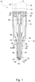
- a diesel fuel injector 10 having a general elongated shape extending along a main axis A and comprising, from bottom to top, a nozzle assembly 12, a control valve assembly 14 and an actuator assembly 16. These assemblies are fixed to each other via a capnut 15.
- the details of the actuator assembly 16 and control valve assembly 14 are known in the art and are not shown in the figures, being simply indicated by boxes.
- the injector 10 defines an internal high pressure fuel circuit 18 comprising several segments and extending from an inlet section 18 provided in the upper part of the injector to spray holes 20 arranged in a lower spray extremity 22 drawn at the very bottom of the injector 10.
- the nozzle assembly 12 comprises a nozzle body 24 having a peripheral wall 26 defining an inner bore 28 in which is slideably arranged a needle 30, forming the valve member, and adapted to translate along the main axis A between a closed position CP and an open position OP.
- the needle valve member 30 has an elongated shaft core 32 extending (along needle axis concentric with axis A) between a top head end 33 and a lower end with a tapered tip 34.
- the needle 30 is provided with a radially protruding collar member 36 that extends toward a circular edge that lies close to the inner face of the inner bore 28 of the nozzle body 26.
- the collar member 36 divides the inner bore 28 into an upstream chamber 38 and a downstream chamber 40 and, a permanently open fluid communication is defined between these chambers by at least one restricted aperture provided in the collar member 36, or at the periphery of it or, along the circular edge.
- Reference sign 42 designates a guide collar similar to collar member 36 to guide the needle 30 in the lower region of bore 28.
- the spray extremity 22 is the arrangement of the tapered end 34 of the needle defining a male needle seating face 44 cooperating with a corresponding female nozzle seating face 46 defined on the inner face of the nozzle body 24.
- the needle seating face 44 is also said to be mobile because it moves with the needle, whereas the nozzle seating face 46 is referred to as fixed seating face.
- the inner bore 28 that is cylindrical, downwardly narrows forming said female nozzle seating face 46 ending in a small sac 48 wherefrom depart the spray holes 20 extending through the peripheral wall 26 of the nozzle body 24.
- An opening position (OP) of the needle 30 is a position where the needle 30 is off the valve seat, i.e. there is a space between the male seating face 44 and female seating face 46, whereby fuel can flow through this space downstream of the valve seat to the spray orifices 20, so that fuel is sprayed at the injector tip into the combustion chamber.
- Actuation of the needle 30 is performed by energizing the actuator assembly 16, typically a solenoid that acts on a valve member of the control valve assembly 14.
- the control valve assembly 14 is conventionally connected with a control chamber 50 at the top of the nozzle assembly 12, in which the needle head 33 (opposite tip 34) protrudes.
- Energizing the actuator 16 will thus cause triggering of the control valve (connected to a mobile armature of the solenoid actuator) that will open an escape path for fuel out of control chamber 50. This will cause a decrease of pressure in the control chamber 50, whereby needle 230 will move upward into the control chamber in OP and thus open the valve seat.
- This principle of operation is well known.
- Fuel injector 10 further comprises a detection circuit for detecting needle opening and closing, which is also referred to as closed loop. In the present embodiment, this is achieved by a simple switch function.
- the needle 30 is axially guided in its upper region by a guide member 54 that is set to a predetermined electric potential.
- the guide member 54 has an axial bore in which the needle head 33 is received.
- the needle 30 is mounted in the nozzle body 24 so as to be able to move therein while being electrically isolated from the nozzle body 24, except for the region of the nozzle body seat 46, so that the needle 30 is in electric contact with the nozzle body 24 only in CP.
- the needle 30 is electrically insulated from the body 24 by means of insulating sheeting or coatings indicated 56 provided at the collars 40, 42 and at the interface with the guide member 54.
- the circuit When the needle is in CP, the circuit is closed and an electric current can flow from the upper guide 56 through the length of the needle 30 to pass into the body 24 at the needle tip in contact with the female seating face 46.
- This detection circuit and flow path is indicated by line 58 in Fig.1 .
- the detection circuit When the needle 30 is in OP, the detection circuit is open and no current can flow to the body 24. There, in CP the voltage may thus be 0 V whereas in OP the circuit is open a predetermined voltage, e.g. 5 V, is measured.
- the needle 30 is designed to include a local dissymmetry in the region above the male seating face 44.
- the local dissymmetry is configured to cause, in use, a transversal force exerted by the fuel in the region of the needle tip 34.
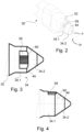
- the needle tip 34 is shown in more details at Figs. 2 to 4 .
- a general rule of design of an injector needle is to have an overall symmetrical shape in order to maintain balance of the opening forces and to avoid lateral forces applied to the needle.
- the needle 30 has an overall symmetrical shape.
- the core shaft 32 exhibits a symmetry of revolution (i.e. circular symmetry) about the needle axis A.
- this may also be the case for the annular collars 36, 42.
- the collar members 36 and 42 may not have an axial symmetry but a symmetry with respect to a plane passing through the needle axis A, still chosen to maintain a proper balance of forces.
- the core shaft 32 terminates with the tapering end 34 which comprises an intermediate section 34.1 followed by a conical section 34.2.
- the intermediate section 34.1 and conical section 34.2 generally have circular symmetry about axis A, except for a certain portion of the periphery at 59 that is modified to provide a local dissymmetry configured to cause, in use, a transversal force (in a given direction) exerted by the fuel about the needle tip 34.
- the local dissymmetry 59 is obtained by machining (milling or grinding) a part of the outer periphery of the conical section 34.2.
- the conical section 34.2 is initially a cone, or more precisely a cone with truncated apex, and the milling thus results in an interruption of the axial symmetry of the conical section 34.2.
- the conical section 34.2 has a symmetry of revolution about axis A (i.e. a circular cross-section) except over a predetermined angular section that may be generally in the range of 35° to 60°.
- the male and female seating faces 44 and 46 have a certain axial extent, in the CP the configuration is such that there is a continuous, circumferential contact line that forms the actual sealing contact between the seating faces.
- the contact line on the male seating face 44 is represented by dashed line 60.
- the local dissymmetry is provided on the male seating face 44 of the needle 30, above the contact line 60 (adjacent thereto on the side of the intermediate section 34.1).
- this local dissymmetry does not have any effect.
- the local dissymmetry causes, at opening, an unbalance of forces on the needle tip that results in a transversal/radial force. This will impact the injector operation at the very beginning of the needle opening, i.e. within the first microns of the lift-off stroke. Due to the transversal forces, the needle is pushed on the side and remains in contact with the female seating face.
- This design thus promotes the contact between the needle tip 34, precisely the conical section 34.2, and the female seating face 46, thereby avoiding oscillations or random needle behavior that may be observed under certain conditions.
- the needle tip 34 is forced to remain in contact with the female seat 46 until it has been sufficiently lifted. Accordingly, the seat detection circuit remains closed during this initial period, leading to a stable electric signal.
- the local dissymmetry may extend into the the intermediate section 34.1, as seen in Figs 3 and 4 . This is due here to the use of the grinding tool that attacks the conical section 34.2 parallel to axis A.
- the conical tip 34.2 may comprise several conical sections along axis A with different angles. This is e.g. the case in this embodiment where the cone angle of the section downstream (on the right) of the contact line 60 is larger than the upstream one (on the left).
- the conical section 34.2 may also be configured with a local dissymmetry in the region below of the contact line 60 (towards the free end). Such dissymmetry should correspond angularly to the one above the contact line 60. The additional dissymmetry will promote flow on one side of the needle at opening and hence increase the transversal force on the needle.
- the local dissymmetry is here obtained by an interruption in the circular outer shape of the conical section, over a minor part of the circumference.
- the needle being typically made in one piece, it is a solid of revolution and the dissymmetry is obtained here by removing material at one location of the periphery.
- the aim is to modify the outer shape of the intermediate section to cause an unbalance of forces that pushes the needle in one direction.
- the intermediate section will thus have, over at least part of its length, a circular cross-section except at the position of the removed material 59 at the tip, preferably just above contact line 60.
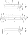
- FIG. 6 Two further embodiments are represented in Figs. 6 and 7 , and will be explained with comparison to Fig.5 , which illustrates the conventional needle design.
- Fig.5 illustrates the conventional needle design.
- a conventional needle 130 having a shaft core 132 with tapering end 134 extending along a main axis A.
- the tapering end includes an intermediate section 135.1 extending between the core end and a conical section 135.2.
- the needle has a symmetry of revolution about axis A.
- Intermediate section 135.1 and conical section 135.2 are also symmetrical about axis A; they have a strictly circular cross-section in a plane perpendicular to axis A, this over their entire axial extent.
- the needle 230 has a core 232 with a symmetry of revolution about axis A. This is however not the case for the intermediate section 232.1.
- the seat line 260 is configured to be tilted relative to the needle axis A.
- the outer shape of the tapering end 234 is made, above the seat line, based on a generatrix parallel to axis A and following the seat line 60 (which thus forms the directrix).
- the region of the conical section 234.2 is thus symmetrical below the seat line, with a circular cross-section.
- the transition section does not have a circular cross-section.
- the design of a needle tip 234 results in an dissymmetric intermediate section 234.1.
- the dashed surface 259 represents the removed portion compared to a circular design.
- the tapering end 334 has been offset from the main axis A of needle 330.
- the shaft core 332 has a symmetry of revolution about axis A.
- the intermediate section 334.1 and conical section 334.2 have a symmetry of revolution about an axis B parallel to axis A but offset therefrom.
Landscapes
- Engineering & Computer Science (AREA)
- Chemical & Material Sciences (AREA)
- Combustion & Propulsion (AREA)
- Mechanical Engineering (AREA)
- General Engineering & Computer Science (AREA)
- Analytical Chemistry (AREA)
- Physics & Mathematics (AREA)
- Fluid Mechanics (AREA)
- Fuel-Injection Apparatus (AREA)
Claims (8)
- Düsenanordnung eines Kraftstoffinjektors, umfassend:eine Düse (12) mit einem Körper (24), der sich entlang einer Hauptachse erstreckt, wobei der Körper eine Umfangswand (26) aufweist und eine Innenbohrung (28) definiert, in der eine Nadel (30) axial bewegbar ist zwischen einer geschlossenen Position, in der ein erstes Ende (34) der Nadel auf einem Ventilsitz aufliegt, um eine Kraftstoffeinspritzung durch eine oder mehrere Einspritzöffnungen (20) der Düse hindurch zu verhindern, und einer offenen Position, in der die Nadel von dem Sitz abgehoben ist, um eine Einspritzung zu erlauben;wobei sich die Nadel entlang einer Nadelachse (A) erstreckt und eine Gesamtform mit einer Rotationssymmetrie um die Nadelachse (A) herum aufweist, wobei die Nadel einen Schaftabschnitt (32) umfasst, der an dem ersten Ende (34) verjüngt ist und eine ringförmige Sitzfläche (44) definiert, die mit einer Sitzfläche (46) an dem Ventilsitz zusammenwirkt;wobei die Düsenanordnung des Weiteren eine Detektionsschaltung aufweist, in der die Nadel einen Schalter bildet;wobei die Nadel so ausgebildet ist, dass sie in der Region der ringförmigen Sitzfläche (44) eine lokale Asymmetrie (59) aufweist, die dazu eingerichtet ist, im Gebrauch ein Kräfte-Ungleichgewicht zu verursachen, das zu einer Querkraft führt, die durch den Kraftstoff um das erste Ende (34) der Nadel herum ausgeübt wird, und wobei das sich verjüngende erste Ende eine Zwischensektion (34.1) aufweist, die an einem Ende mit dem Nadelschaftabschnitt (32) und am anderen Ende mit einer konischen Sektion (34.2), die die ringförmige Sitzfläche (44) definiert, verbunden ist,wobei die konische Sektion (34.2) dazu eingerichtet ist, eine Kontaktlinie (60) in einer Ebene im Wesentlichen senkrecht zu der Nadelachse (A) zu definieren,dadurch gekennzeichnet, dass sich die lokale Asymmetrie (59) neben der Kontaktlinie auf der Seite der Zwischensektion (34.1) befindet,wobei die konische Sektion (34.2) eine Kreissymmetrie um die Nadelachse (A) herum aufweist, außer über einer zuvor festgelegten Winkelsektion, die kleiner als 180° ist, undwobei die lokale Asymmetrie durch einen trunkierten Umfangsabschnitt der konischen Sektion gebildet wird, der zum Beispiel durch maschinelle Bearbeitung entfernt wurde.
- Düsenanordnung nach Anspruch 1, wobei die zuvor festgelegte Winkelsektion im Bereich von 20 bis 90°, insbesondere 35 bis 60°, liegt.
- Düsenanordnung nach Anspruch 1, wobei die konische Sektion einen weiteren trunkierten Umfangsabschnitt auf der gegenüberliegenden Seite der Kontaktlinie umfasst.
- Düsenanordnung nach Anspruch 1, wobei die konische Sektion (234.2) dazu eingerichtet ist, eine Kontaktlinie (260) in einer Ebene zu definieren, die in Bezug auf die Nadelachse (A) geneigt ist, und die äußere Form der verjüngten Spitze oberhalb der Kontaktlinie durch eine Erzeugende definiert ist, die parallel zu der Nadelachse verläuft und der Kontaktlinie folgt.
- Düsenanordnung nach Anspruch 1, wobei die Zwischensektion (334.1) und die konische Sektion (334.2) eine Symmetrieachse aufweisen, die als Spitzenachse (B) bezeichnet wird und die parallel zu der Nadelachse (A) und von dieser versetzt verläuft.
- Düsenanordnung nach Anspruch 5, wobei die Zwischensektion und die konische Sektion eine Kreissymmetrie um die Spitzenachse herum aufweisen.
- Düsenanordnung nach einem der vorangehenden Ansprüche, wobei der Nadelschaft (32) eine Rotationssymmetrie um die Achse (A) herum aufweist und bevorzugt mindestens ein Bundelement (46) umfasst, das eine Rotationssymmetrie um die Achse (A) herum oder um eine durch die Achse (A) verlaufende Ebene herum aufweist.
- Kraftstoffinjektor, umfassend eine Düsenanordnung nach einem der vorangehenden Ansprüche.
Applications Claiming Priority (2)
| Application Number | Priority Date | Filing Date | Title |
|---|---|---|---|
| GB1812525.2A GB2576146B (en) | 2018-08-01 | 2018-08-01 | Fuel injector with closed loop detection |
| PCT/EP2019/068279 WO2020025262A1 (en) | 2018-08-01 | 2019-07-08 | Fuel injector with closed loop detection |
Publications (2)
| Publication Number | Publication Date |
|---|---|
| EP3830405A1 EP3830405A1 (de) | 2021-06-09 |
| EP3830405B1 true EP3830405B1 (de) | 2025-06-04 |
Family
ID=63518272
Family Applications (1)
| Application Number | Title | Priority Date | Filing Date |
|---|---|---|---|
| EP19737723.7A Active EP3830405B1 (de) | 2018-08-01 | 2019-07-08 | Kraftstoffinjektor mit erkennung von geschlossenem kreislauf |
Country Status (3)
| Country | Link |
|---|---|
| EP (1) | EP3830405B1 (de) |
| GB (1) | GB2576146B (de) |
| WO (1) | WO2020025262A1 (de) |
Family Cites Families (5)
| Publication number | Priority date | Publication date | Assignee | Title |
|---|---|---|---|---|
| DE2841967A1 (de) * | 1978-09-27 | 1980-04-10 | Daimler Benz Ag | Mehrloch-einspritzduese fuer luftverdichtende brennkraftmaschinen |
| DE19907899A1 (de) * | 1999-02-24 | 2000-08-31 | Bosch Gmbh Robert | Brennstoffeinspritzventil |
| EP1283336B1 (de) * | 2001-08-06 | 2007-04-11 | Toyota Jidosha Kabushiki Kaisha | Brennkraftmaschine |
| GB201602694D0 (en) * | 2016-02-16 | 2016-03-30 | Delphi Internat Operations Luxembourg S À R L | Nozzle assembly and fuel injector |
| WO2017167627A1 (fr) * | 2016-04-01 | 2017-10-05 | Delphi International Operations Luxembourg S.À R.L. | Injecteur de carburant |
-
2018
- 2018-08-01 GB GB1812525.2A patent/GB2576146B/en active Active
-
2019
- 2019-07-08 WO PCT/EP2019/068279 patent/WO2020025262A1/en not_active Ceased
- 2019-07-08 EP EP19737723.7A patent/EP3830405B1/de active Active
Also Published As
| Publication number | Publication date |
|---|---|
| GB201812525D0 (en) | 2018-09-12 |
| GB2576146B (en) | 2021-06-02 |
| WO2020025262A1 (en) | 2020-02-06 |
| EP3830405A1 (de) | 2021-06-09 |
| GB2576146A (en) | 2020-02-12 |
Similar Documents
| Publication | Publication Date | Title |
|---|---|---|
| EP2369166B1 (de) | Einspritzdüse | |
| KR960013110B1 (ko) | 연료 분사 밸브용 중공체 | |
| KR20100080374A (ko) | 내연기관의 높은 작동 반복성 및 안정성을 갖는 연료분사 시스템 | |
| US20020162906A1 (en) | Fuel injection valve for internal combustion engines | |
| US4506833A (en) | Fuel injection nozzle for an internal combustion engine | |
| EP1988281A1 (de) | Einspritzdüse | |
| CN101529080A (zh) | 用于将燃料喷入内燃机燃烧室中的喷射器 | |
| EP3830405B1 (de) | Kraftstoffinjektor mit erkennung von geschlossenem kreislauf | |
| US9371807B2 (en) | Method and device for setting an idle stroke of an actuating drive of an injection valve, and injector assembly | |
| EP2905457B1 (de) | Ventilanordnung und Flüssigkeitseinspritzdüse für eine Brennkraftmaschine | |
| KR20040086443A (ko) | 연료 분사 밸브 | |
| US20160230728A1 (en) | Plunger And Fluid-Line System | |
| JP5606750B2 (ja) | 燃焼機関のための燃料噴射ノズル | |
| EP3990772B1 (de) | Kraftstoffinjektor mit erkennung von geschlossenem kreislauf | |
| KR100631298B1 (ko) | 연료 분사 밸브 | |
| KR20180096656A (ko) | 연료 분사 밸브 | |
| KR101949061B1 (ko) | 유체 분사용 인젝터 | |
| US20070272772A1 (en) | Injection Nozzle | |
| KR102625916B1 (ko) | 유체 측정용 밸브 | |
| CN114502834A (zh) | 用于内燃机的燃料喷射器 | |
| EP2246557B1 (de) | Injektor zum Einspritzen von Fluid | |
| KR20160098246A (ko) | 연료 분사 노즐 | |
| EP2975255B1 (de) | Düsenkörper, Ventilanordnung und Flüssigkeitseinspritzventil | |
| EP3997327B1 (de) | Fluidinjektor einer brennkraftmaschine mit einem ventilsitzkörper | |
| US8727240B2 (en) | Fuel injector |
Legal Events
| Date | Code | Title | Description |
|---|---|---|---|
| STAA | Information on the status of an ep patent application or granted ep patent |
Free format text: STATUS: UNKNOWN |
|
| STAA | Information on the status of an ep patent application or granted ep patent |
Free format text: STATUS: THE INTERNATIONAL PUBLICATION HAS BEEN MADE |
|
| PUAI | Public reference made under article 153(3) epc to a published international application that has entered the european phase |
Free format text: ORIGINAL CODE: 0009012 |
|
| STAA | Information on the status of an ep patent application or granted ep patent |
Free format text: STATUS: REQUEST FOR EXAMINATION WAS MADE |
|
| 17P | Request for examination filed |
Effective date: 20210301 |
|
| AK | Designated contracting states |
Kind code of ref document: A1 Designated state(s): AL AT BE BG CH CY CZ DE DK EE ES FI FR GB GR HR HU IE IS IT LI LT LU LV MC MK MT NL NO PL PT RO RS SE SI SK SM TR |
|
| DAV | Request for validation of the european patent (deleted) | ||
| DAX | Request for extension of the european patent (deleted) | ||
| P01 | Opt-out of the competence of the unified patent court (upc) registered |
Effective date: 20230327 |
|
| STAA | Information on the status of an ep patent application or granted ep patent |
Free format text: STATUS: EXAMINATION IS IN PROGRESS |
|
| 17Q | First examination report despatched |
Effective date: 20230621 |
|
| RAP1 | Party data changed (applicant data changed or rights of an application transferred) |
Owner name: PHINIA DELPHI LUXEMBOURG SARL |
|
| GRAP | Despatch of communication of intention to grant a patent |
Free format text: ORIGINAL CODE: EPIDOSNIGR1 |
|
| STAA | Information on the status of an ep patent application or granted ep patent |
Free format text: STATUS: GRANT OF PATENT IS INTENDED |
|
| INTG | Intention to grant announced |
Effective date: 20250115 |
|
| GRAS | Grant fee paid |
Free format text: ORIGINAL CODE: EPIDOSNIGR3 |
|
| GRAA | (expected) grant |
Free format text: ORIGINAL CODE: 0009210 |
|
| STAA | Information on the status of an ep patent application or granted ep patent |
Free format text: STATUS: THE PATENT HAS BEEN GRANTED |
|
| AK | Designated contracting states |
Kind code of ref document: B1 Designated state(s): AL AT BE BG CH CY CZ DE DK EE ES FI FR GB GR HR HU IE IS IT LI LT LU LV MC MK MT NL NO PL PT RO RS SE SI SK SM TR |
|
| REG | Reference to a national code |
Ref country code: GB Ref legal event code: FG4D |
|
| REG | Reference to a national code |
Ref country code: CH Ref legal event code: EP |
|
| REG | Reference to a national code |
Ref country code: DE Ref legal event code: R096 Ref document number: 602019070747 Country of ref document: DE |
|
| REG | Reference to a national code |
Ref country code: IE Ref legal event code: FG4D |
|
| REG | Reference to a national code |
Ref country code: NL Ref legal event code: MP Effective date: 20250604 |
|
| PG25 | Lapsed in a contracting state [announced via postgrant information from national office to epo] |
Ref country code: FI Free format text: LAPSE BECAUSE OF FAILURE TO SUBMIT A TRANSLATION OF THE DESCRIPTION OR TO PAY THE FEE WITHIN THE PRESCRIBED TIME-LIMIT Effective date: 20250604 Ref country code: ES Free format text: LAPSE BECAUSE OF FAILURE TO SUBMIT A TRANSLATION OF THE DESCRIPTION OR TO PAY THE FEE WITHIN THE PRESCRIBED TIME-LIMIT Effective date: 20250604 |
|
| PGFP | Annual fee paid to national office [announced via postgrant information from national office to epo] |
Ref country code: DE Payment date: 20250714 Year of fee payment: 7 |
|
| REG | Reference to a national code |
Ref country code: LT Ref legal event code: MG9D |
|
| PG25 | Lapsed in a contracting state [announced via postgrant information from national office to epo] |
Ref country code: GR Free format text: LAPSE BECAUSE OF FAILURE TO SUBMIT A TRANSLATION OF THE DESCRIPTION OR TO PAY THE FEE WITHIN THE PRESCRIBED TIME-LIMIT Effective date: 20250905 Ref country code: NO Free format text: LAPSE BECAUSE OF FAILURE TO SUBMIT A TRANSLATION OF THE DESCRIPTION OR TO PAY THE FEE WITHIN THE PRESCRIBED TIME-LIMIT Effective date: 20250904 |
|
| PG25 | Lapsed in a contracting state [announced via postgrant information from national office to epo] |
Ref country code: PL Free format text: LAPSE BECAUSE OF FAILURE TO SUBMIT A TRANSLATION OF THE DESCRIPTION OR TO PAY THE FEE WITHIN THE PRESCRIBED TIME-LIMIT Effective date: 20250604 |
|
| PG25 | Lapsed in a contracting state [announced via postgrant information from national office to epo] |
Ref country code: BG Free format text: LAPSE BECAUSE OF FAILURE TO SUBMIT A TRANSLATION OF THE DESCRIPTION OR TO PAY THE FEE WITHIN THE PRESCRIBED TIME-LIMIT Effective date: 20250604 |
|
| PGFP | Annual fee paid to national office [announced via postgrant information from national office to epo] |
Ref country code: GB Payment date: 20250911 Year of fee payment: 7 |
|
| PG25 | Lapsed in a contracting state [announced via postgrant information from national office to epo] |
Ref country code: HR Free format text: LAPSE BECAUSE OF FAILURE TO SUBMIT A TRANSLATION OF THE DESCRIPTION OR TO PAY THE FEE WITHIN THE PRESCRIBED TIME-LIMIT Effective date: 20250604 |
|
| PGFP | Annual fee paid to national office [announced via postgrant information from national office to epo] |
Ref country code: FR Payment date: 20250912 Year of fee payment: 7 |
|
| PG25 | Lapsed in a contracting state [announced via postgrant information from national office to epo] |
Ref country code: RS Free format text: LAPSE BECAUSE OF FAILURE TO SUBMIT A TRANSLATION OF THE DESCRIPTION OR TO PAY THE FEE WITHIN THE PRESCRIBED TIME-LIMIT Effective date: 20250904 |
|
| PG25 | Lapsed in a contracting state [announced via postgrant information from national office to epo] |
Ref country code: LV Free format text: LAPSE BECAUSE OF FAILURE TO SUBMIT A TRANSLATION OF THE DESCRIPTION OR TO PAY THE FEE WITHIN THE PRESCRIBED TIME-LIMIT Effective date: 20250604 |
|
| PG25 | Lapsed in a contracting state [announced via postgrant information from national office to epo] |
Ref country code: NL Free format text: LAPSE BECAUSE OF FAILURE TO SUBMIT A TRANSLATION OF THE DESCRIPTION OR TO PAY THE FEE WITHIN THE PRESCRIBED TIME-LIMIT Effective date: 20250604 |
|
| PG25 | Lapsed in a contracting state [announced via postgrant information from national office to epo] |
Ref country code: PT Free format text: LAPSE BECAUSE OF FAILURE TO SUBMIT A TRANSLATION OF THE DESCRIPTION OR TO PAY THE FEE WITHIN THE PRESCRIBED TIME-LIMIT Effective date: 20251006 |
|
| REG | Reference to a national code |
Ref country code: AT Ref legal event code: MK05 Ref document number: 1800536 Country of ref document: AT Kind code of ref document: T Effective date: 20250604 |
|
| PG25 | Lapsed in a contracting state [announced via postgrant information from national office to epo] |
Ref country code: IS Free format text: LAPSE BECAUSE OF FAILURE TO SUBMIT A TRANSLATION OF THE DESCRIPTION OR TO PAY THE FEE WITHIN THE PRESCRIBED TIME-LIMIT Effective date: 20251004 |
|
| PG25 | Lapsed in a contracting state [announced via postgrant information from national office to epo] |
Ref country code: AT Free format text: LAPSE BECAUSE OF FAILURE TO SUBMIT A TRANSLATION OF THE DESCRIPTION OR TO PAY THE FEE WITHIN THE PRESCRIBED TIME-LIMIT Effective date: 20250604 Ref country code: SM Free format text: LAPSE BECAUSE OF FAILURE TO SUBMIT A TRANSLATION OF THE DESCRIPTION OR TO PAY THE FEE WITHIN THE PRESCRIBED TIME-LIMIT Effective date: 20250604 |
|
| PG25 | Lapsed in a contracting state [announced via postgrant information from national office to epo] |
Ref country code: CZ Free format text: LAPSE BECAUSE OF FAILURE TO SUBMIT A TRANSLATION OF THE DESCRIPTION OR TO PAY THE FEE WITHIN THE PRESCRIBED TIME-LIMIT Effective date: 20250604 |
|
| PG25 | Lapsed in a contracting state [announced via postgrant information from national office to epo] |
Ref country code: EE Free format text: LAPSE BECAUSE OF FAILURE TO SUBMIT A TRANSLATION OF THE DESCRIPTION OR TO PAY THE FEE WITHIN THE PRESCRIBED TIME-LIMIT Effective date: 20250604 |
|
| PG25 | Lapsed in a contracting state [announced via postgrant information from national office to epo] |
Ref country code: RO Free format text: LAPSE BECAUSE OF FAILURE TO SUBMIT A TRANSLATION OF THE DESCRIPTION OR TO PAY THE FEE WITHIN THE PRESCRIBED TIME-LIMIT Effective date: 20250604 Ref country code: SK Free format text: LAPSE BECAUSE OF FAILURE TO SUBMIT A TRANSLATION OF THE DESCRIPTION OR TO PAY THE FEE WITHIN THE PRESCRIBED TIME-LIMIT Effective date: 20250604 |
|
| PG25 | Lapsed in a contracting state [announced via postgrant information from national office to epo] |
Ref country code: IT Free format text: LAPSE BECAUSE OF FAILURE TO SUBMIT A TRANSLATION OF THE DESCRIPTION OR TO PAY THE FEE WITHIN THE PRESCRIBED TIME-LIMIT Effective date: 20250604 |
|
| REG | Reference to a national code |
Ref country code: CH Ref legal event code: H13 Free format text: ST27 STATUS EVENT CODE: U-0-0-H10-H13 (AS PROVIDED BY THE NATIONAL OFFICE) Effective date: 20260224 |
|
| PG25 | Lapsed in a contracting state [announced via postgrant information from national office to epo] |
Ref country code: LU Free format text: LAPSE BECAUSE OF NON-PAYMENT OF DUE FEES Effective date: 20250708 |