EP3829672B1 - Intravascular pump with controls and display screen on handle - Google Patents
Intravascular pump with controls and display screen on handle Download PDFInfo
- Publication number
- EP3829672B1 EP3829672B1 EP19844949.8A EP19844949A EP3829672B1 EP 3829672 B1 EP3829672 B1 EP 3829672B1 EP 19844949 A EP19844949 A EP 19844949A EP 3829672 B1 EP3829672 B1 EP 3829672B1
- Authority
- EP
- European Patent Office
- Prior art keywords
- impeller
- blood
- handle
- motor
- display portion
- Prior art date
- Legal status (The legal status is an assumption and is not a legal conclusion. Google has not performed a legal analysis and makes no representation as to the accuracy of the status listed.)
- Active
Links
- 239000008280 blood Substances 0.000 claims description 39
- 210000004369 blood Anatomy 0.000 claims description 39
- 239000000411 inducer Substances 0.000 claims description 12
- 230000017531 blood circulation Effects 0.000 claims description 9
- 210000005166 vasculature Anatomy 0.000 claims description 7
- 238000000034 method Methods 0.000 claims description 6
- 230000036772 blood pressure Effects 0.000 claims description 4
- QVGXLLKOCUKJST-UHFFFAOYSA-N atomic oxygen Chemical compound [O] QVGXLLKOCUKJST-UHFFFAOYSA-N 0.000 claims description 2
- 238000004891 communication Methods 0.000 claims description 2
- 229910052760 oxygen Inorganic materials 0.000 claims description 2
- 239000001301 oxygen Substances 0.000 claims description 2
- 210000005246 left atrium Anatomy 0.000 description 5
- 239000000463 material Substances 0.000 description 5
- 210000004204 blood vessel Anatomy 0.000 description 4
- 210000005240 left ventricle Anatomy 0.000 description 4
- 210000005241 right ventricle Anatomy 0.000 description 4
- 230000002861 ventricular Effects 0.000 description 4
- 210000000709 aorta Anatomy 0.000 description 3
- 210000001765 aortic valve Anatomy 0.000 description 3
- 210000001105 femoral artery Anatomy 0.000 description 3
- 238000009413 insulation Methods 0.000 description 3
- 229920000642 polymer Polymers 0.000 description 3
- 210000005245 right atrium Anatomy 0.000 description 3
- 210000000591 tricuspid valve Anatomy 0.000 description 3
- 208000007536 Thrombosis Diseases 0.000 description 2
- 210000002376 aorta thoracic Anatomy 0.000 description 2
- 230000008859 change Effects 0.000 description 2
- 239000011248 coating agent Substances 0.000 description 2
- 238000000576 coating method Methods 0.000 description 2
- 210000003709 heart valve Anatomy 0.000 description 2
- 210000004115 mitral valve Anatomy 0.000 description 2
- 210000003102 pulmonary valve Anatomy 0.000 description 2
- 238000005086 pumping Methods 0.000 description 2
- 230000009467 reduction Effects 0.000 description 2
- 239000013589 supplement Substances 0.000 description 2
- 230000007704 transition Effects 0.000 description 2
- 206010018910 Haemolysis Diseases 0.000 description 1
- 241000274177 Juniperus sabina Species 0.000 description 1
- 230000009471 action Effects 0.000 description 1
- 230000001154 acute effect Effects 0.000 description 1
- 229910045601 alloy Inorganic materials 0.000 description 1
- 239000000956 alloy Substances 0.000 description 1
- 210000001367 artery Anatomy 0.000 description 1
- 230000008901 benefit Effects 0.000 description 1
- 230000009084 cardiovascular function Effects 0.000 description 1
- 239000004020 conductor Substances 0.000 description 1
- 238000010276 construction Methods 0.000 description 1
- 230000001419 dependent effect Effects 0.000 description 1
- 238000013461 design Methods 0.000 description 1
- 238000011161 development Methods 0.000 description 1
- 230000006870 function Effects 0.000 description 1
- PCHJSUWPFVWCPO-UHFFFAOYSA-N gold Chemical compound [Au] PCHJSUWPFVWCPO-UHFFFAOYSA-N 0.000 description 1
- 229910052737 gold Inorganic materials 0.000 description 1
- 239000010931 gold Substances 0.000 description 1
- 210000004013 groin Anatomy 0.000 description 1
- 230000005802 health problem Effects 0.000 description 1
- 208000019622 heart disease Diseases 0.000 description 1
- 230000008588 hemolysis Effects 0.000 description 1
- 230000010354 integration Effects 0.000 description 1
- 210000004072 lung Anatomy 0.000 description 1
- 238000005259 measurement Methods 0.000 description 1
- 229910001092 metal group alloy Inorganic materials 0.000 description 1
- 238000012986 modification Methods 0.000 description 1
- 230000004048 modification Effects 0.000 description 1
- 238000012544 monitoring process Methods 0.000 description 1
- HLXZNVUGXRDIFK-UHFFFAOYSA-N nickel titanium Chemical compound [Ti].[Ti].[Ti].[Ti].[Ti].[Ti].[Ti].[Ti].[Ti].[Ti].[Ti].[Ni].[Ni].[Ni].[Ni].[Ni].[Ni].[Ni].[Ni].[Ni].[Ni].[Ni].[Ni].[Ni].[Ni] HLXZNVUGXRDIFK-UHFFFAOYSA-N 0.000 description 1
- 229910001000 nickel titanium Inorganic materials 0.000 description 1
- 230000008569 process Effects 0.000 description 1
- 210000001147 pulmonary artery Anatomy 0.000 description 1
- 210000003492 pulmonary vein Anatomy 0.000 description 1
- 238000011160 research Methods 0.000 description 1
- 235000001520 savin Nutrition 0.000 description 1
- 238000000926 separation method Methods 0.000 description 1
- 239000012781 shape memory material Substances 0.000 description 1
- 239000010935 stainless steel Substances 0.000 description 1
- 229910001220 stainless steel Inorganic materials 0.000 description 1
- 238000001356 surgical procedure Methods 0.000 description 1
- 229910052715 tantalum Inorganic materials 0.000 description 1
- GUVRBAGPIYLISA-UHFFFAOYSA-N tantalum atom Chemical compound [Ta] GUVRBAGPIYLISA-UHFFFAOYSA-N 0.000 description 1
- 238000013519 translation Methods 0.000 description 1
- 210000001631 vena cava inferior Anatomy 0.000 description 1
- 210000002620 vena cava superior Anatomy 0.000 description 1
Images


Classifications
-
- A—HUMAN NECESSITIES
- A61—MEDICAL OR VETERINARY SCIENCE; HYGIENE
- A61M—DEVICES FOR INTRODUCING MEDIA INTO, OR ONTO, THE BODY; DEVICES FOR TRANSDUCING BODY MEDIA OR FOR TAKING MEDIA FROM THE BODY; DEVICES FOR PRODUCING OR ENDING SLEEP OR STUPOR
- A61M5/00—Devices for bringing media into the body in a subcutaneous, intra-vascular or intramuscular way; Accessories therefor, e.g. filling or cleaning devices, arm-rests
- A61M5/14—Infusion devices, e.g. infusing by gravity; Blood infusion; Accessories therefor
- A61M5/142—Pressure infusion, e.g. using pumps
- A61M5/14212—Pumping with an aspiration and an expulsion action
- A61M5/14236—Screw, impeller or centrifugal type pumps
-
- A—HUMAN NECESSITIES
- A61—MEDICAL OR VETERINARY SCIENCE; HYGIENE
- A61M—DEVICES FOR INTRODUCING MEDIA INTO, OR ONTO, THE BODY; DEVICES FOR TRANSDUCING BODY MEDIA OR FOR TAKING MEDIA FROM THE BODY; DEVICES FOR PRODUCING OR ENDING SLEEP OR STUPOR
- A61M60/00—Blood pumps; Devices for mechanical circulatory actuation; Balloon pumps for circulatory assistance
- A61M60/10—Location thereof with respect to the patient's body
- A61M60/122—Implantable pumps or pumping devices, i.e. the blood being pumped inside the patient's body
- A61M60/126—Implantable pumps or pumping devices, i.e. the blood being pumped inside the patient's body implantable via, into, inside, in line, branching on, or around a blood vessel
- A61M60/148—Implantable pumps or pumping devices, i.e. the blood being pumped inside the patient's body implantable via, into, inside, in line, branching on, or around a blood vessel in line with a blood vessel using resection or like techniques, e.g. permanent endovascular heart assist devices
-
- A—HUMAN NECESSITIES
- A61—MEDICAL OR VETERINARY SCIENCE; HYGIENE
- A61M—DEVICES FOR INTRODUCING MEDIA INTO, OR ONTO, THE BODY; DEVICES FOR TRANSDUCING BODY MEDIA OR FOR TAKING MEDIA FROM THE BODY; DEVICES FOR PRODUCING OR ENDING SLEEP OR STUPOR
- A61M5/00—Devices for bringing media into the body in a subcutaneous, intra-vascular or intramuscular way; Accessories therefor, e.g. filling or cleaning devices, arm-rests
- A61M5/14—Infusion devices, e.g. infusing by gravity; Blood infusion; Accessories therefor
- A61M5/142—Pressure infusion, e.g. using pumps
- A61M5/14244—Pressure infusion, e.g. using pumps adapted to be carried by the patient, e.g. portable on the body
- A61M5/14276—Pressure infusion, e.g. using pumps adapted to be carried by the patient, e.g. portable on the body specially adapted for implantation
-
- A—HUMAN NECESSITIES
- A61—MEDICAL OR VETERINARY SCIENCE; HYGIENE
- A61M—DEVICES FOR INTRODUCING MEDIA INTO, OR ONTO, THE BODY; DEVICES FOR TRANSDUCING BODY MEDIA OR FOR TAKING MEDIA FROM THE BODY; DEVICES FOR PRODUCING OR ENDING SLEEP OR STUPOR
- A61M60/00—Blood pumps; Devices for mechanical circulatory actuation; Balloon pumps for circulatory assistance
- A61M60/10—Location thereof with respect to the patient's body
- A61M60/122—Implantable pumps or pumping devices, i.e. the blood being pumped inside the patient's body
- A61M60/126—Implantable pumps or pumping devices, i.e. the blood being pumped inside the patient's body implantable via, into, inside, in line, branching on, or around a blood vessel
- A61M60/13—Implantable pumps or pumping devices, i.e. the blood being pumped inside the patient's body implantable via, into, inside, in line, branching on, or around a blood vessel by means of a catheter allowing explantation, e.g. catheter pumps temporarily introduced via the vascular system
-
- A—HUMAN NECESSITIES
- A61—MEDICAL OR VETERINARY SCIENCE; HYGIENE
- A61M—DEVICES FOR INTRODUCING MEDIA INTO, OR ONTO, THE BODY; DEVICES FOR TRANSDUCING BODY MEDIA OR FOR TAKING MEDIA FROM THE BODY; DEVICES FOR PRODUCING OR ENDING SLEEP OR STUPOR
- A61M60/00—Blood pumps; Devices for mechanical circulatory actuation; Balloon pumps for circulatory assistance
- A61M60/20—Type thereof
- A61M60/205—Non-positive displacement blood pumps
- A61M60/216—Non-positive displacement blood pumps including a rotating member acting on the blood, e.g. impeller
-
- A—HUMAN NECESSITIES
- A61—MEDICAL OR VETERINARY SCIENCE; HYGIENE
- A61M—DEVICES FOR INTRODUCING MEDIA INTO, OR ONTO, THE BODY; DEVICES FOR TRANSDUCING BODY MEDIA OR FOR TAKING MEDIA FROM THE BODY; DEVICES FOR PRODUCING OR ENDING SLEEP OR STUPOR
- A61M60/00—Blood pumps; Devices for mechanical circulatory actuation; Balloon pumps for circulatory assistance
- A61M60/40—Details relating to driving
- A61M60/403—Details relating to driving for non-positive displacement blood pumps
- A61M60/408—Details relating to driving for non-positive displacement blood pumps the force acting on the blood contacting member being mechanical, e.g. transmitted by a shaft or cable
- A61M60/411—Details relating to driving for non-positive displacement blood pumps the force acting on the blood contacting member being mechanical, e.g. transmitted by a shaft or cable generated by an electromotor
- A61M60/414—Details relating to driving for non-positive displacement blood pumps the force acting on the blood contacting member being mechanical, e.g. transmitted by a shaft or cable generated by an electromotor transmitted by a rotating cable, e.g. for blood pumps mounted on a catheter
-
- A—HUMAN NECESSITIES
- A61—MEDICAL OR VETERINARY SCIENCE; HYGIENE
- A61M—DEVICES FOR INTRODUCING MEDIA INTO, OR ONTO, THE BODY; DEVICES FOR TRANSDUCING BODY MEDIA OR FOR TAKING MEDIA FROM THE BODY; DEVICES FOR PRODUCING OR ENDING SLEEP OR STUPOR
- A61M60/00—Blood pumps; Devices for mechanical circulatory actuation; Balloon pumps for circulatory assistance
- A61M60/40—Details relating to driving
- A61M60/403—Details relating to driving for non-positive displacement blood pumps
- A61M60/408—Details relating to driving for non-positive displacement blood pumps the force acting on the blood contacting member being mechanical, e.g. transmitted by a shaft or cable
- A61M60/411—Details relating to driving for non-positive displacement blood pumps the force acting on the blood contacting member being mechanical, e.g. transmitted by a shaft or cable generated by an electromotor
- A61M60/416—Details relating to driving for non-positive displacement blood pumps the force acting on the blood contacting member being mechanical, e.g. transmitted by a shaft or cable generated by an electromotor transmitted directly by the motor rotor drive shaft
-
- A—HUMAN NECESSITIES
- A61—MEDICAL OR VETERINARY SCIENCE; HYGIENE
- A61M—DEVICES FOR INTRODUCING MEDIA INTO, OR ONTO, THE BODY; DEVICES FOR TRANSDUCING BODY MEDIA OR FOR TAKING MEDIA FROM THE BODY; DEVICES FOR PRODUCING OR ENDING SLEEP OR STUPOR
- A61M60/00—Blood pumps; Devices for mechanical circulatory actuation; Balloon pumps for circulatory assistance
- A61M60/40—Details relating to driving
- A61M60/403—Details relating to driving for non-positive displacement blood pumps
- A61M60/422—Details relating to driving for non-positive displacement blood pumps the force acting on the blood contacting member being electromagnetic, e.g. using canned motor pumps
-
- A—HUMAN NECESSITIES
- A61—MEDICAL OR VETERINARY SCIENCE; HYGIENE
- A61M—DEVICES FOR INTRODUCING MEDIA INTO, OR ONTO, THE BODY; DEVICES FOR TRANSDUCING BODY MEDIA OR FOR TAKING MEDIA FROM THE BODY; DEVICES FOR PRODUCING OR ENDING SLEEP OR STUPOR
- A61M60/00—Blood pumps; Devices for mechanical circulatory actuation; Balloon pumps for circulatory assistance
- A61M60/50—Details relating to control
- A61M60/508—Electronic control means, e.g. for feedback regulation
- A61M60/515—Regulation using real-time patient data
- A61M60/531—Regulation using real-time patient data using blood pressure data, e.g. from blood pressure sensors
-
- A—HUMAN NECESSITIES
- A61—MEDICAL OR VETERINARY SCIENCE; HYGIENE
- A61M—DEVICES FOR INTRODUCING MEDIA INTO, OR ONTO, THE BODY; DEVICES FOR TRANSDUCING BODY MEDIA OR FOR TAKING MEDIA FROM THE BODY; DEVICES FOR PRODUCING OR ENDING SLEEP OR STUPOR
- A61M60/00—Blood pumps; Devices for mechanical circulatory actuation; Balloon pumps for circulatory assistance
- A61M60/50—Details relating to control
- A61M60/508—Electronic control means, e.g. for feedback regulation
- A61M60/538—Regulation using real-time blood pump operational parameter data, e.g. motor current
- A61M60/546—Regulation using real-time blood pump operational parameter data, e.g. motor current of blood flow, e.g. by adapting rotor speed
-
- A—HUMAN NECESSITIES
- A61—MEDICAL OR VETERINARY SCIENCE; HYGIENE
- A61M—DEVICES FOR INTRODUCING MEDIA INTO, OR ONTO, THE BODY; DEVICES FOR TRANSDUCING BODY MEDIA OR FOR TAKING MEDIA FROM THE BODY; DEVICES FOR PRODUCING OR ENDING SLEEP OR STUPOR
- A61M60/00—Blood pumps; Devices for mechanical circulatory actuation; Balloon pumps for circulatory assistance
- A61M60/50—Details relating to control
- A61M60/585—User interfaces
-
- A—HUMAN NECESSITIES
- A61—MEDICAL OR VETERINARY SCIENCE; HYGIENE
- A61M—DEVICES FOR INTRODUCING MEDIA INTO, OR ONTO, THE BODY; DEVICES FOR TRANSDUCING BODY MEDIA OR FOR TAKING MEDIA FROM THE BODY; DEVICES FOR PRODUCING OR ENDING SLEEP OR STUPOR
- A61M2205/00—General characteristics of the apparatus
- A61M2205/33—Controlling, regulating or measuring
- A61M2205/3331—Pressure; Flow
- A61M2205/3334—Measuring or controlling the flow rate
-
- A—HUMAN NECESSITIES
- A61—MEDICAL OR VETERINARY SCIENCE; HYGIENE
- A61M—DEVICES FOR INTRODUCING MEDIA INTO, OR ONTO, THE BODY; DEVICES FOR TRANSDUCING BODY MEDIA OR FOR TAKING MEDIA FROM THE BODY; DEVICES FOR PRODUCING OR ENDING SLEEP OR STUPOR
- A61M2205/00—General characteristics of the apparatus
- A61M2205/33—Controlling, regulating or measuring
- A61M2205/3331—Pressure; Flow
- A61M2205/3344—Measuring or controlling pressure at the body treatment site
-
- A—HUMAN NECESSITIES
- A61—MEDICAL OR VETERINARY SCIENCE; HYGIENE
- A61M—DEVICES FOR INTRODUCING MEDIA INTO, OR ONTO, THE BODY; DEVICES FOR TRANSDUCING BODY MEDIA OR FOR TAKING MEDIA FROM THE BODY; DEVICES FOR PRODUCING OR ENDING SLEEP OR STUPOR
- A61M2205/00—General characteristics of the apparatus
- A61M2205/33—Controlling, regulating or measuring
- A61M2205/3365—Rotational speed
-
- A—HUMAN NECESSITIES
- A61—MEDICAL OR VETERINARY SCIENCE; HYGIENE
- A61M—DEVICES FOR INTRODUCING MEDIA INTO, OR ONTO, THE BODY; DEVICES FOR TRANSDUCING BODY MEDIA OR FOR TAKING MEDIA FROM THE BODY; DEVICES FOR PRODUCING OR ENDING SLEEP OR STUPOR
- A61M2205/00—General characteristics of the apparatus
- A61M2205/50—General characteristics of the apparatus with microprocessors or computers
- A61M2205/502—User interfaces, e.g. screens or keyboards
-
- A—HUMAN NECESSITIES
- A61—MEDICAL OR VETERINARY SCIENCE; HYGIENE
- A61M—DEVICES FOR INTRODUCING MEDIA INTO, OR ONTO, THE BODY; DEVICES FOR TRANSDUCING BODY MEDIA OR FOR TAKING MEDIA FROM THE BODY; DEVICES FOR PRODUCING OR ENDING SLEEP OR STUPOR
- A61M2230/00—Measuring parameters of the user
- A61M2230/04—Heartbeat characteristics, e.g. ECG, blood pressure modulation
- A61M2230/06—Heartbeat rate only
-
- A—HUMAN NECESSITIES
- A61—MEDICAL OR VETERINARY SCIENCE; HYGIENE
- A61M—DEVICES FOR INTRODUCING MEDIA INTO, OR ONTO, THE BODY; DEVICES FOR TRANSDUCING BODY MEDIA OR FOR TAKING MEDIA FROM THE BODY; DEVICES FOR PRODUCING OR ENDING SLEEP OR STUPOR
- A61M2230/00—Measuring parameters of the user
- A61M2230/20—Blood composition characteristics
-
- A—HUMAN NECESSITIES
- A61—MEDICAL OR VETERINARY SCIENCE; HYGIENE
- A61M—DEVICES FOR INTRODUCING MEDIA INTO, OR ONTO, THE BODY; DEVICES FOR TRANSDUCING BODY MEDIA OR FOR TAKING MEDIA FROM THE BODY; DEVICES FOR PRODUCING OR ENDING SLEEP OR STUPOR
- A61M2230/00—Measuring parameters of the user
- A61M2230/30—Blood pressure
Definitions
- the invention relates to an intravascular blood pump with controls and display screen on the handle.
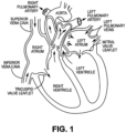
- the human heart comprises four chambers and four heart valves that assist in the forward (antegrade) flow of blood through the heart.
- the chambers include the left atrium, left ventricle, right atrium and right ventricle.
- the four heart valves include the mitral valve, the tricuspid valve, the aortic valve and the pulmonary valve.
- the mitral valve is located between the left atrium and left ventricle and helps control the flow of blood from the left atrium to the left ventricle by acting as a one-way valve to prevent backflow into the left atrium.
- the tricuspid valve is located between the right atrium and the right ventricle, while the aortic valve and the pulmonary valve are semilunar valves located in arteries flowing blood away from the heart.
- the valves are all one-way valves, with leaflets that open to allow forward (antegrade) blood flow. The normally functioning valve leaflets close under the pressure exerted by reverse blood to prevent backflow (retrograde) of the blood.
- the general blood flow comprises deoxygenated blood returning from the body where it is received by the right atrium via the superior and inferior vena cava and is, in turn, pumped into the right ventricle, a process controlled by the tricuspid valve.
- the right ventricle functions to pump the deoxygenated blood to the lungs via the pulmonary arteries, where the blood is reoxygenated and returned to the left atrium via the pulmonary veins.
- Heart disease is a health problem with a high mortality rate.
- the use of temporary mechanical blood pump devices are used on an increasingly frequent basis to provide short-term acute support during surgery or as temporary bridging support to help a patient survive a crisis.
- These temporary blood pumps have developed and evolved over the years to supplement the pumping action of the heart on a short-term basis and supplement blood flow as either left or right ventricular assist devices, with the left ventricular assist device ("LVAD”) currently the most commonly used device.
- LVAD left ventricular assist device
- LVAD devices generally are delivered percutaneously, e.g., through the femoral artery, to locate or position the LVAD inlet in the patient's left ventricle and the outlet in the patient's ascending aorta with the body of the device disposed across the aortic valve.
- an incision may be made below the patient's groin to enable access to the patient's femoral artery. The physician may then translate guide wire, followed by a catheter or delivery sheath, through the femoral artery and descending aorta until reaching the ascending aorta.
- the LVAD with attached rotational drive shaft may then be translated through the delivery catheter or sheath lumen, leaving a proximal end of the drive shaft exposed outside of the patient and coupled with a prime mover such as an electric motor or the equivalent for rotating and controlling the rotational speed of the drive shaft and associated LVAD impeller.
- a prime mover such as an electric motor or the equivalent for rotating and controlling the rotational speed of the drive shaft and associated LVAD impeller.
- Temporary axial flow blood pumps consist generally of two types: (1) those that are powered by a motor integrated into the device that is connected with the pump's impeller ( see US Pat. Nos. 5,147,388 and 5,275,580 ) ; and (2) those that are powered by an external motor that provides rotational torque to a drive shaft which is, in turn, connected to the pump's impeller ( see US Pat. Nos. 4,625,712 to Wampler and US Patent 5,112,349 to Summers ).
- VAD temporary ventricle assist devices
- LVAD left ventricular assist
- RVAD right ventricular assist
- LVAD left ventricular assist
- LVAD right ventricular assist
- LVAD left ventricular assist
- RVAD right ventricular assist
- the known device 2 is oriented with the inflow end (distal end) on the left side of the drawing and the outflow end (proximal) on the right side, so that the incoming blood flow in the ventricle enters the device housing through the inflow aperture(s) (not shown), flows through the defined by the surrounding housing 14, ultimately entering the impeller/pump assembly 4. There, the incoming blood encounters the flow inducer 6 before being urged forward by the rotating impeller 8. The blood flow may then be modified by a flow diffuser 9 and exits into the aorta via the housing's outflow aperture(s) 10.
- Known VAD or LVAD devices further comprise a delivery configuration and a functional or working configuration, with the delivery configuration having a lower profile or smaller diameter than the functional or working configuration to, inter alia, facilitate atraumatic delivery through a delivery sheath.
- the housing of the VAD or LVAD, and/or the blades of the impeller may expand to achieve the functional or working configuration and collapse to achieve the delivery configuration.
- known devices collapse and expand the impeller blades and/or the housing wherein the collapsible and expandable housing surrounds at least a portion of the impeller in order to enable moving between an expanded or working configuration and/or require an integrated motor proximate the impeller. See, e.g., US Pat. Nos. 7,027,875 ; 7,927,068 ; and 8,992,163 .
- LVAD devices will typically comprise an angled housing to accommodate the aortic arch, the angle or bend generally in the range of 135 degrees.
- LVAD devices with integrated motors within the housing must be small enough to allow atraumatic intravascular translation and positioning within the heart.
- various means are known to collapse portions of the device while within the catheter or delivery sheath, including the housing and/or the impeller or parts thereof such as the blades, the size of the collapsed device may be limited by the integrated motor.
- the known LVAD devices comprise a delivery configuration wherein the housing and/or impeller, e.g., the blades on the impeller, may be reduced in diameter and, when delivered distally from the delivery catheter or sheath, the collapsed elements are enabled to expand.
- the collapsing and expanding comprises at least a portion of the housing that is occupied by the impeller.
- the inflow region of the housing that is the region distal to the rotational impeller and the stationary inducer or flow straightener, comprises an area of opportunity to optimize blood flow through the cannula or housing.
- Known LVAD or VAD devices do not take advantage of this opportunity.
- VAD or VAD devices comprise a stationary inducer or flow straightener encountered by blood upon entry into the pump which can contribute to, inter alia, thrombosis and/or hemolysis.
- reducing crossing profile of the VAD or LVAD device is critical for reasons discussed herein, a design requirement made more difficult by the need to extend electric leads across or along the housing of the device, wherein the electrical leads may be used for, e.g., powering and/or communicating with a motor or sensor(s) or other operational powered element.
- electric leads require profile reduction to keep the crossing profile as low as possible, as well as insulation and/or spacing between adjacent leads where such insulation and/or spacing is necessary or desired.
- CA 3 039 302 A1 describes apparatus and methods including a blood pump configured to be placed inside a blood vessel of a subject, the blood pump including an impeller configured to pump blood by rotating.
- a support cage is shaped to define a narrow portion that is configured to be disposed around the impeller, and to maintain a separation between a wall of the blood vessel and the impeller, and a radial extension from the narrow portion of the support cage that extends radially outward with respect to the narrow portion of the support cage, the radial extension being configured to substantially maintain a longitudinal axis of the impeller in alignment with a local longitudinal axis of the blood vessel by contacting the wall of the blood vessel.
- a control unit controls pumps by controlling rotation of impellers.
- Impellers of pumps are coupled to one or more motors, which impart rotational motion to the impellers, via one or more rotation shafts.
- the motors are disposed outside of the subject's body.
- User interface displays the subject's current lower-body venous pressure, renal venous pressure, and/or central venous pressure, based upon the signals generated by sensors.
- US 2017/340789 A1 describes an intravascular right ventricular assist device.
- US 2018/078159 A1 describes systems, devices, and methods that use a heart pump to obtain measurements of cardiovascular function.
- various embodiments of the present invention are directed to mechanical assist devices for pumping blood in a patient.
- Improved temporary LVAD or VAD blood pumps are described herein that are delivered percutaneously and intravascularly.
- an exemplary LVAD blood pump 100 is illustrated, with inflow apertures 12 on the left side of the illustration and outflow apertures 10 on the right side of the device.
- the motor is shown as located on the proximal end of the device outside the patient's body and connected with a rotational drive shaft that is, in turn, connected with the impeller or rotor 8 or pump assembly.
- outer housing 14 The entire length of outer housing 14 is shown as comprising a relatively constant diameter from the inlet or inflow apertures 12 to the outlet or outflow apertures 10.
- Guide wire 16 is positioned alongside the exterior of the device until reaching the inlet apertures 12 where it enters the lumen of cannula C and extends distally therefrom as shown. Thus, the guide wire 16 does not pass through the impeller or rotor 8 or pump assembly.
- the configuration shown in Fig. 3 may comprise a delivery configuration with an expandable region 102 compressed within an introducer or delivery sheath or catheter 200.
- device 100 may comprise an expandable region 102 that may be located distal to the impeller or rotor or pump assembly, such that the housing diameter surrounding the impeller or rotor or pump assembly does not change diameter during delivery or during rotation.
- a proximal non-expandable region 122 may be provided and comprises at least the impeller or rotor or pump assembly and the housing surrounding that assembly does not expand or contract appreciably but may be flexible.
- a distal non-expandable region 124 may also be provided comprising at least the inlet region including at least the inlet apertures 12.
- the expandable region 102 comprises a proximal end and a distal end.
- the proximal end of the expandable region 102 abuts or is adjacent to a distal end of the proximal non-expandable region 122 while the distal end of the expandable region 102 abuts or is adjacent to a proximal end of the distal non-expandable region 124.
- the housing H surrounding the non-expandable region(s) 122, 124 may, however, be flexible or pliable, but they are not disposed to a biased expansion.
- housing H of device 100 in Figure 3 may be non-expandable.
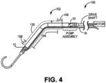
- Figure 4 illustrates an expandable embodiment of device 100 and in dashed lines the change in diameter to/from a collapsed, deformed expandable region to an exemplary expanded undeformed expandable region, extending distally from a point distal to the end of the impeller, rotor and/or pump assembly along the hollow cannula to a point just proximal of the inlet apertures.
- the expandable region 102 may expand to a maximum undeformed diameter within the range of 12-20 Fr, more preferably between 16-20 Fr.
- the unexpanded region remains at a substantially fixed diameter within the range of 9 to 12 Fr.
- the device 100 may comprise an expandable region 102 that may be, either partially or completely, biased to the expanded configuration and, therefore, comprise a material or structure that facilitates expansion and may be biased to expand.
- Exemplary construction of the expandable region 102 may comprise a support structure 130 that is surrounded by an outer material, e.g., a jacket or coating or sleeve comprised of a plastic or polymeric material that accommodates an expansion of the underlying support structure as is known in the art.
- the support structure 130 may be formed of a shape memory material, for example Nitinol or similar.
- expandable region 102 may comprise gold, tantalum, stainless steel, metal alloys, aerospace alloys and/or polymers including polymers that expand and contract upon exposure to relative heat and cold.
- expandable region 102 e.g., a central expandable section 104 discussed infra
- Figure 4 provides a rotational drive shaft connected with the impeller assembly and is, in turn, connected with a prime mover such as an electric motor that is located outside the patient's body.
- device 100 may comprise an expandable housing H or region 102 or may be non-expandable.
- the expandable region 102 may comprise a single expandable region, without need or reason to distinguish between a proximal transition section, central expandable section and/or distal transition section.
- the expandable region 102 of the present invention may comprise a support structure 130 surrounded by a polymer coating or jacket that adapts to expansion and collapsing of the expandable region 102.
- the support structure 130 may comprise an expandable stent-like structure formed of a series of cells formed from interacting and/or interconnected wires and/or struts and that enable collapsing and biased expansion of a structure, e.g., a stent, as is known in the art.
- a structure e.g., a stent
- expandable region 102 described herein is merely exemplary and not limiting in any regard. As such, any expandable housing H of a blood pump device 100 is readily adaptable to the various embodiments of the present invention relating to insulation and/or spacing and/or profile reduction or integration of electrical leads or conductors E within or along the blood pump housing. Expandable region 102 may also comprise a single region capable of expansion and collapse.
- FIG. 5 an exemplary pump assembly or impeller assembly 200 is illustrated.
- the exemplary pump or impeller assembly of Fig. 5 completely eliminates the flow inducer 6 and the flow diffuser 9 of the impeller assembly found in known pumps.
- the inducer 6 and/or diffuser 9 are not needed for effective control or manipulation of the incoming blood flow and that the additional stationary surface area and interconnections between at least the inducer 6 and the distal end of the rotating impeller 8 provide increased risk of thrombosis.
- the blood is induced to flow through the cannula of by actuating the pump or impeller assembly to rotate at a predetermined speed, without aid or requirement of a flow inducer.
- the blood thus flows directly to the rotating impeller 8 comprising blades 11 and is urged out of the cannula or lumen of the device at outlet apertures 10 by the rotating impeller blades 11, without aid or requirement of a flow diffuser or straightener.
- FIGS. 6-8B embodiments of a blood pump assembly comprising a handle with control buttons and a display on the handle are provided.
- An external rotational motor is provided in operational engagement with a drive shaft that is, in turn, operationally engaged with the impeller assembly.
- a blood pump assembly of the present invention comprises
- the impeller assembly and/or impeller may comprise a flow inducer and/or flow straightener, while in other embodiments no flow inducer or flow straightener is required.
- the motor is disposed within the handle with a rotational drive shaft disposed within the sheath and in operative engagement with the rotational motor and the impeller assembly.
- Figure 6 shows the physiological parameters on a display with controls for controlling the operational parameters that may be adjusted according to the displayed physiological parameters being or trending high or low compared with desired physiological parameter targets.
- Fig. 7 shows one embodiment of the handle in operative connection with an impeller asssembly and any physiological sensors along the sheath and/or in or proximate to the impeller assembly.
- electrical leads may be translated through the sheath to operatively connect the handle with a motor and/or impeller assembly and/or physiological parameter sensors or operational sensors such as pressure of flow or flow rate generated or induced by the rotating impeller.
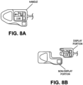
- Figures 8A and 8B illustrate one embodiment wherein the handle comprises a reusable display portion and a non-reusable non-display portion.
- the display portion may be removably connnected with and to the non-display portion to enable operative functioning and monitoring as described above.
- the display portion may be disconnected and reused with another non-display portion and in another blood pump procedure.
Description
- This application claims priority to
U.S. Non-Provisional Patent Application No. 16/524791, filed July 29, 2019 U.S. Provisional Patent Application No. 62/712,409, filed July 31, 2018 - Not Applicable
- The invention relates to an intravascular blood pump with controls and display screen on the handle.
- With reference to
Figure 1 , the human heart comprises four chambers and four heart valves that assist in the forward (antegrade) flow of blood through the heart. The chambers include the left atrium, left ventricle, right atrium and right ventricle. The four heart valves include the mitral valve, the tricuspid valve, the aortic valve and the pulmonary valve. - The mitral valve is located between the left atrium and left ventricle and helps control the flow of blood from the left atrium to the left ventricle by acting as a one-way valve to prevent backflow into the left atrium. Similarly, the tricuspid valve is located between the right atrium and the right ventricle, while the aortic valve and the pulmonary valve are semilunar valves located in arteries flowing blood away from the heart. The valves are all one-way valves, with leaflets that open to allow forward (antegrade) blood flow. The normally functioning valve leaflets close under the pressure exerted by reverse blood to prevent backflow (retrograde) of the blood.
- Thus, as illustrated, the general blood flow comprises deoxygenated blood returning from the body where it is received by the right atrium via the superior and inferior vena cava and is, in turn, pumped into the right ventricle, a process controlled by the tricuspid valve. The right ventricle functions to pump the deoxygenated blood to the lungs via the pulmonary arteries, where the blood is reoxygenated and returned to the left atrium via the pulmonary veins.
- Heart disease is a health problem with a high mortality rate. The use of temporary mechanical blood pump devices are used on an increasingly frequent basis to provide short-term acute support during surgery or as temporary bridging support to help a patient survive a crisis. These temporary blood pumps have developed and evolved over the years to supplement the pumping action of the heart on a short-term basis and supplement blood flow as either left or right ventricular assist devices, with the left ventricular assist device ("LVAD") currently the most commonly used device.
- Known temporary LVAD devices generally are delivered percutaneously, e.g., through the femoral artery, to locate or position the LVAD inlet in the patient's left ventricle and the outlet in the patient's ascending aorta with the body of the device disposed across the aortic valve. As the skilled artisan will understand, an incision may be made below the patient's groin to enable access to the patient's femoral artery. The physician may then translate guide wire, followed by a catheter or delivery sheath, through the femoral artery and descending aorta until reaching the ascending aorta. The LVAD with attached rotational drive shaft may then be translated through the delivery catheter or sheath lumen, leaving a proximal end of the drive shaft exposed outside of the patient and coupled with a prime mover such as an electric motor or the equivalent for rotating and controlling the rotational speed of the drive shaft and associated LVAD impeller.
- Temporary axial flow blood pumps consist generally of two types: (1) those that are powered by a motor integrated into the device that is connected with the pump's impeller (see
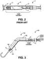
US Pat. Nos. 5,147,388 and5,275,580 ) ; and (2) those that are powered by an external motor that provides rotational torque to a drive shaft which is, in turn, connected to the pump's impeller (seeUS Pat. Nos. 4,625,712 to Wampler andUS Patent 5,112,349 to Summers ). - Known temporary ventricle assist devices ("VAD"), including LVAD and RVAD (right ventricular assist) devices, whether with integrated motor or an external motor, generally comprise the following elements mounted within a housing, listed in order from the inflow end to the outflow end: an inflow aperture(s); a flow inducer, known in the art as component that directs flow into the impeller from the inflow apertures or inlet; a rotational impeller; and a flow diffuser and/or outflow structure known in the art as functioning to straighten or redirecting the rotational flow created by the rotational impeller into axial flow; and an outflow aperture(s) as shown in the exemplary prior art pump and/or impeller assembly cross sectional and cutaway view of
Figure 2 . - In
Fig. 2 , theknown device 2 is oriented with the inflow end (distal end) on the left side of the drawing and the outflow end (proximal) on the right side, so that the incoming blood flow in the ventricle enters the device housing through the inflow aperture(s) (not shown), flows through the defined by the surroundinghousing 14, ultimately entering the impeller/pump assembly 4. There, the incoming blood encounters the flow inducer 6 before being urged forward by the rotatingimpeller 8. The blood flow may then be modified by aflow diffuser 9 and exits into the aorta via the housing's outflow aperture(s) 10. - Known VAD or LVAD devices further comprise a delivery configuration and a functional or working configuration, with the delivery configuration having a lower profile or smaller diameter than the functional or working configuration to, inter alia, facilitate atraumatic delivery through a delivery sheath. Stated differently, through various means the housing of the VAD or LVAD, and/or the blades of the impeller, may expand to achieve the functional or working configuration and collapse to achieve the delivery configuration. However, known devices collapse and expand the impeller blades and/or the housing wherein the collapsible and expandable housing surrounds at least a portion of the impeller in order to enable moving between an expanded or working configuration and/or require an integrated motor proximate the impeller. See, e.g.,
US Pat. Nos. 7,027,875 ;7,927,068 ; and8,992,163 . - Known LVAD devices will typically comprise an angled housing to accommodate the aortic arch, the angle or bend generally in the range of 135 degrees.
- LVAD devices with integrated motors within the housing must be small enough to allow atraumatic intravascular translation and positioning within the heart. Though various means are known to collapse portions of the device while within the catheter or delivery sheath, including the housing and/or the impeller or parts thereof such as the blades, the size of the collapsed device may be limited by the integrated motor.
- In addition, the known LVAD devices comprise a delivery configuration wherein the housing and/or impeller, e.g., the blades on the impeller, may be reduced in diameter and, when delivered distally from the delivery catheter or sheath, the collapsed elements are enabled to expand. These devices are limited in several respects. First, the collapsing and expanding comprises at least a portion of the housing that is occupied by the impeller. Second, the inflow region of the housing, that is the region distal to the rotational impeller and the stationary inducer or flow straightener, comprises an area of opportunity to optimize blood flow through the cannula or housing. Known LVAD or VAD devices do not take advantage of this opportunity. Third, known LVAD or VAD devices comprise a stationary inducer or flow straightener encountered by blood upon entry into the pump which can contribute to, inter alia, thrombosis and/or hemolysis. Fourth, reducing crossing profile of the VAD or LVAD device is critical for reasons discussed herein, a design requirement made more difficult by the need to extend electric leads across or along the housing of the device, wherein the electrical leads may be used for, e.g., powering and/or communicating with a motor or sensor(s) or other operational powered element. In this connection, electric leads require profile reduction to keep the crossing profile as low as possible, as well as insulation and/or spacing between adjacent leads where such insulation and/or spacing is necessary or desired.
-
CA 3 039 302 A1 describes apparatus and methods including a blood pump configured to be placed inside a blood vessel of a subject, the blood pump including an impeller configured to pump blood by rotating. A support cage is shaped to define a narrow portion that is configured to be disposed around the impeller, and to maintain a separation between a wall of the blood vessel and the impeller, and a radial extension from the narrow portion of the support cage that extends radially outward with respect to the narrow portion of the support cage, the radial extension being configured to substantially maintain a longitudinal axis of the impeller in alignment with a local longitudinal axis of the blood vessel by contacting the wall of the blood vessel. For some applications, a control unit controls pumps by controlling rotation of impellers. Impellers of pumps are coupled to one or more motors, which impart rotational motion to the impellers, via one or more rotation shafts. The motors are disposed outside of the subject's body. User interface displays the subject's current lower-body venous pressure, renal venous pressure, and/or central venous pressure, based upon the signals generated by sensors. -
US 2017/340789 A1 describes an intravascular right ventricular assist device. -
US 2018/078159 A1 describes systems, devices, and methods that use a heart pump to obtain measurements of cardiovascular function. - Various embodiments of the present invention address these, inter alia, issues. The figures and the detailed description which follow more particularly exemplify these and other embodiments of the invention.
- The problems of the related art are solved by a blood pump assembly having the features of the independent claim. Additional features for advantageous embodiments are provided in the dependent claims.
-
-
FIG. 1 is a cutaway view of the human heart; -
FIG. 2 is a cross-sectional view of a prior art device; -
FIG. 3 is a side cutaway view of one embodiment of the present invention; -
FIG. 4 is a side cutaway view of one embodiment of the present invention; -
FIG. 5 is a side cutaway of one embodiment of the present invention; -
FIG. 6 is a top view cutaway view of a handle of one embodiment of the present invention; -
FIG. 7 is a perspective view of one embodiment of the present invention; -
FIG. 8A is a top view of a handle with a display portion connected with a non-display portion; and -
FIG. 8B is a top view of the handle ofFIG. 8A wherein the display portion is disconnected from the non-display portion. - Generally, various embodiments of the present invention are directed to mechanical assist devices for pumping blood in a patient. Improved temporary LVAD or VAD blood pumps are described herein that are delivered percutaneously and intravascularly.
- Referring now to
Figure 3 , an exemplaryLVAD blood pump 100 is illustrated, withinflow apertures 12 on the left side of the illustration andoutflow apertures 10 on the right side of the device. The motor is shown as located on the proximal end of the device outside the patient's body and connected with a rotational drive shaft that is, in turn, connected with the impeller orrotor 8 or pump assembly. - The entire length of
outer housing 14 is shown as comprising a relatively constant diameter from the inlet orinflow apertures 12 to the outlet oroutflow apertures 10.Guide wire 16 is positioned alongside the exterior of the device until reaching theinlet apertures 12 where it enters the lumen of cannula C and extends distally therefrom as shown. Thus, theguide wire 16 does not pass through the impeller orrotor 8 or pump assembly. The configuration shown inFig. 3 may comprise a delivery configuration with anexpandable region 102 compressed within an introducer or delivery sheath orcatheter 200. - With reference generally to the Figures,
device 100 may comprise anexpandable region 102 that may be located distal to the impeller or rotor or pump assembly, such that the housing diameter surrounding the impeller or rotor or pump assembly does not change diameter during delivery or during rotation. Stated differently, a proximal non-expandable region 122 may be provided and comprises at least the impeller or rotor or pump assembly and the housing surrounding that assembly does not expand or contract appreciably but may be flexible. Further, a distalnon-expandable region 124 may also be provided comprising at least the inlet region including at least theinlet apertures 12. Thus, theexpandable region 102 comprises a proximal end and a distal end. The proximal end of theexpandable region 102 abuts or is adjacent to a distal end of the proximal non-expandable region 122 while the distal end of theexpandable region 102 abuts or is adjacent to a proximal end of the distalnon-expandable region 124. The housing H surrounding the non-expandable region(s) 122, 124 may, however, be flexible or pliable, but they are not disposed to a biased expansion. - Alternatively, the housing H of
device 100 inFigure 3 may be non-expandable. -
Figure 4 illustrates an expandable embodiment ofdevice 100 and in dashed lines the change in diameter to/from a collapsed, deformed expandable region to an exemplary expanded undeformed expandable region, extending distally from a point distal to the end of the impeller, rotor and/or pump assembly along the hollow cannula to a point just proximal of the inlet apertures. Theexpandable region 102 may expand to a maximum undeformed diameter within the range of 12-20 Fr, more preferably between 16-20 Fr. In contrast, the unexpanded region remains at a substantially fixed diameter within the range of 9 to 12 Fr. - With continued reference to
Figs 3 and4 , and the remaining Figures generally, thedevice 100 may comprise anexpandable region 102 that may be, either partially or completely, biased to the expanded configuration and, therefore, comprise a material or structure that facilitates expansion and may be biased to expand. Exemplary construction of theexpandable region 102 may comprise asupport structure 130 that is surrounded by an outer material, e.g., a jacket or coating or sleeve comprised of a plastic or polymeric material that accommodates an expansion of the underlying support structure as is known in the art. Thesupport structure 130 may be formed of a shape memory material, for example Nitinol or similar. Other materials may comprise gold, tantalum, stainless steel, metal alloys, aerospace alloys and/or polymers including polymers that expand and contract upon exposure to relative heat and cold. In other cases, at least a portion of theexpandable region 102, e.g., a centralexpandable section 104 discussed infra, may comprise a polymeric or other material sleeve that is configured to allow and/or accommodate expansion and collapsing and asupport structure 130 may be omitted.Figure 4 provides a rotational drive shaft connected with the impeller assembly and is, in turn, connected with a prime mover such as an electric motor that is located outside the patient's body. Further, as discussed above,device 100 may comprise an expandable housing H orregion 102 or may be non-expandable. - In many of the embodiments described herein, the
expandable region 102 may comprise a single expandable region, without need or reason to distinguish between a proximal transition section, central expandable section and/or distal transition section. - Generally, the
expandable region 102 of the present invention may comprise asupport structure 130 surrounded by a polymer coating or jacket that adapts to expansion and collapsing of theexpandable region 102. - Further, the
support structure 130 may comprise an expandable stent-like structure formed of a series of cells formed from interacting and/or interconnected wires and/or struts and that enable collapsing and biased expansion of a structure, e.g., a stent, as is known in the art. For example, seeU.S. Pat Nos. 5,776,183 to Kanesaka ;5,019,090 to Pinchuk ;5,161,547 to Tower ;4,950,227 to Savin ;5,314,472 to Fontaine ;4,886,062 and 4,969,458 to Wiktor 4,856,516 to Hillstead . - The
expandable region 102 described herein is merely exemplary and not limiting in any regard. As such, any expandable housing H of ablood pump device 100 is readily adaptable to the various embodiments of the present invention relating to insulation and/or spacing and/or profile reduction or integration of electrical leads or conductors E within or along the blood pump housing.Expandable region 102 may also comprise a single region capable of expansion and collapse. - Turning now to
Figure 5 , an exemplary pump assembly orimpeller assembly 200 is illustrated. Initially, in contrast to the known impeller assembly shown inFigure 2 which comprises aflow inducer 6 and flowdiffuser 9, the exemplary pump or impeller assembly ofFig. 5 completely eliminates theflow inducer 6 and theflow diffuser 9 of the impeller assembly found in known pumps. Applicant has found that theinducer 6 and/ordiffuser 9 are not needed for effective control or manipulation of the incoming blood flow and that the additional stationary surface area and interconnections between at least theinducer 6 and the distal end of therotating impeller 8 provide increased risk of thrombosis. Thus, the blood is induced to flow through the cannula of by actuating the pump or impeller assembly to rotate at a predetermined speed, without aid or requirement of a flow inducer. The blood thus flows directly to therotating impeller 8 comprisingblades 11 and is urged out of the cannula or lumen of the device atoutlet apertures 10 by the rotatingimpeller blades 11, without aid or requirement of a flow diffuser or straightener. - Turning now to
Figures 6-8B , embodiments of a blood pump assembly comprising a handle with control buttons and a display on the handle are provided. An external rotational motor is provided in operational engagement with a drive shaft that is, in turn, operationally engaged with the impeller assembly. - Generally, a blood pump assembly of the present invention comprises
- a motor in operative rotational engagement with an impeller assembly, the impeller assembly comprising an impeller housing, an impeller within the impeller housing, the impeller comprising an impeller hub and blades in operative engagement with the impeller hub; and
- a handle in operative connection and communication with the motor, wherein the handle comprises controls for controlling at least the motor, and a display integrated into the handle, the display adapted to display real-time physiological parameters and operational parameters, wherein the real-time physiological parameters comprise at least one of the group consisting of: blood pressure, heart rate, electrocardiogram information, and blood oxygen saturation, and
- wherein the real-time operational parameters comprise at least one of the group consisting of: rotational speed, resulting blood flow rate induced by the blood pump within the patient's vasculature, and resulting blood pressure induced by the blood pump within the patient's vasculature.
- In some cases, the impeller assembly and/or impeller may comprise a flow inducer and/or flow straightener, while in other embodiments no flow inducer or flow straightener is required. The motor is disposed within the handle with a rotational drive shaft disposed within the sheath and in operative engagement with the rotational motor and the impeller assembly.
-
Figure 6 shows the physiological parameters on a display with controls for controlling the operational parameters that may be adjusted according to the displayed physiological parameters being or trending high or low compared with desired physiological parameter targets. -
Fig. 7 shows one embodiment of the handle in operative connection with an impeller asssembly and any physiological sensors along the sheath and/or in or proximate to the impeller assembly. As will be readily understood, electrical leads may be translated through the sheath to operatively connect the handle with a motor and/or impeller assembly and/or physiological parameter sensors or operational sensors such as pressure of flow or flow rate generated or induced by the rotating impeller. -
Figures 8A and 8B illustrate one embodiment wherein the handle comprises a reusable display portion and a non-reusable non-display portion. The display portion may be removably connnected with and to the non-display portion to enable operative functioning and monitoring as described above. When a blood pump procedure is completed, the display portion may be disconnected and reused with another non-display portion and in another blood pump procedure. - The description of the invention as set forth herein is illustrative and is not intended to limit the scope of the invention. Features of various embodiments may be combined with other embodiments within the contemplation of this invention. Variations and modifications of the embodiments disclosed herein are possible and practical alternatives to and equivalents of the various elements of the embodiments would be understood to those of ordinary skill in the art upon study of this patent document. The invention is defined by the features of the appended claims.
Claims (4)
- A blood pump assembly adapted for use within a patient's vasculature, comprising:a motor in operative rotational engagement with an impeller assembly (200), the impeller assembly (200) comprising an impeller housing, an impeller (8) within the impeller housing, the impeller (8) comprising an impeller hub and blades (11) in operative engagement with the impeller hub;a handle in operative connection and communication with the motor, wherein the handle comprises controls for controlling at least the motor, and a display integrated into the handle, the display adapted to display real-time physiological parameters and real-time operational parameters, wherein the real-time physiological parameters comprise at least one of the group consisting of: blood pressure, heart rate, electrocardiogram information, and blood oxygen saturation, andwherein the real-time operational parameters comprise at least one of the group consisting of: rotational speed, resulting blood flow rate induced by the blood pump within the patient's vasculature, and resulting blood pressure induced by the blood pump within the patient's vasculature, andfurther comprising a drive shaft in operational rotational engagement with the impeller assembly (200) and the motor, and wherein the motor and handle are located outside of the patient's vasculature and characterized in thatthe motor is located within the handle with the integrated display.
- The blood pump assembly of claim 1, wherein the handle comprises a display portion and a non-display portion, wherein the display portion is adapted to be operatively and removably connected with the non-display portion.
- The blood pump assembly of claim 2, wherein the display portion is adapted for re-use after completing a procedure within the patient's vasculature after disconnecting the re-usable display portion from the used non-display portion.
- The blood pump assembly of claim 1, wherein the impeller assembly (200) does not include a flow inducer or a flow diffuser.
Applications Claiming Priority (3)
| Application Number | Priority Date | Filing Date | Title |
|---|---|---|---|
| US201862712409P | 2018-07-31 | 2018-07-31 | |
| US16/524,791 US11202900B2 (en) | 2018-07-31 | 2019-07-29 | Intravascular pump with controls and display screen on handle |
| PCT/US2019/044040 WO2020028300A1 (en) | 2018-07-31 | 2019-07-30 | Intravascular pump with controls and display screen on handle |
Publications (3)
| Publication Number | Publication Date |
|---|---|
| EP3829672A1 EP3829672A1 (en) | 2021-06-09 |
| EP3829672A4 EP3829672A4 (en) | 2022-08-17 |
| EP3829672B1 true EP3829672B1 (en) | 2024-02-21 |
Family
ID=69228248
Family Applications (1)
| Application Number | Title | Priority Date | Filing Date |
|---|---|---|---|
| EP19844949.8A Active EP3829672B1 (en) | 2018-07-31 | 2019-07-30 | Intravascular pump with controls and display screen on handle |
Country Status (5)
| Country | Link |
|---|---|
| US (1) | US11202900B2 (en) |
| EP (1) | EP3829672B1 (en) |
| JP (1) | JP7187666B2 (en) |
| CN (1) | CN112512622A (en) |
| WO (1) | WO2020028300A1 (en) |
Families Citing this family (4)
| Publication number | Priority date | Publication date | Assignee | Title |
|---|---|---|---|---|
| DE102018201030A1 (en) | 2018-01-24 | 2019-07-25 | Kardion Gmbh | Magnetic coupling element with magnetic bearing function |
| DE102018211327A1 (en) | 2018-07-10 | 2020-01-16 | Kardion Gmbh | Impeller for an implantable vascular support system |
| DE102020102474A1 (en) | 2020-01-31 | 2021-08-05 | Kardion Gmbh | Pump for conveying a fluid and method for manufacturing a pump |
| CN114259646A (en) * | 2022-01-11 | 2022-04-01 | 丰凯利医疗器械(上海)有限公司 | Blood circulation auxiliary device and control system |
Family Cites Families (20)
| Publication number | Priority date | Publication date | Assignee | Title |
|---|---|---|---|---|
| US4625712A (en) | 1983-09-28 | 1986-12-02 | Nimbus, Inc. | High-capacity intravascular blood pump utilizing percutaneous access |
| US4964864A (en) | 1988-09-27 | 1990-10-23 | American Biomed, Inc. | Heart assist pump |
| JPH0636821B2 (en) | 1990-03-08 | 1994-05-18 | 健二 山崎 | Implantable auxiliary artificial heart |
| EP2058017A3 (en) | 1996-10-04 | 2011-02-23 | Tyco Healthcare Group LP | Circulatory support system |
| DE10059714C1 (en) | 2000-12-01 | 2002-05-08 | Impella Cardiotech Ag | Intravasal pump has pump stage fitted with flexible expandible sleeve contricted during insertion through blood vessel |
| US7393181B2 (en) | 2004-09-17 | 2008-07-01 | The Penn State Research Foundation | Expandable impeller pump |
| US8419609B2 (en) | 2005-10-05 | 2013-04-16 | Heartware Inc. | Impeller for a rotary ventricular assist device |
| US7699586B2 (en) | 2004-12-03 | 2010-04-20 | Heartware, Inc. | Wide blade, axial flow pump |
| CN102380135A (en) | 2006-03-23 | 2012-03-21 | 宾州研究基金会 | Heart assist device with expandable impeller pump |
| EP1847281A1 (en) * | 2006-04-20 | 2007-10-24 | Ventrassist Pty Ltd | System and method of controlling a rotary blood pump |
| US7828528B2 (en) | 2007-09-06 | 2010-11-09 | Asante Solutions, Inc. | Occlusion sensing system for infusion pumps |
| US8449444B2 (en) | 2009-02-27 | 2013-05-28 | Thoratec Corporation | Blood flow meter |
| CN102107030B (en) * | 2009-12-28 | 2013-07-17 | 杨碧波 | Cardiac impulse assist device, cardiac impulse assist system and method for treating cardiac failure |
| US9555174B2 (en) * | 2010-02-17 | 2017-01-31 | Flow Forward Medical, Inc. | Blood pump systems and methods |
| US20130253552A1 (en) | 2012-03-20 | 2013-09-26 | Cardiovascular Systems, Inc. | Controller for an atherectomy device |
| US10556050B2 (en) | 2014-07-10 | 2020-02-11 | Thorvascular Pty Ltd | Low cost ventricular device and system thereof |
| US20170340789A1 (en) * | 2016-05-27 | 2017-11-30 | Yale University | Cavo-arterial pump |
| EP3848088A1 (en) | 2016-09-19 | 2021-07-14 | Abiomed, Inc. | Cardiovascular assist system that quantifies heart function and facilitates heart recovery |
| ES2767553T3 (en) | 2016-10-19 | 2020-06-17 | Abiomed Europe Gmbh | Ventricular Assist Device Control |
| WO2018096531A1 (en) | 2016-11-23 | 2018-05-31 | Magenta Medical Ltd. | Blood pumps |
-
2019
- 2019-07-29 US US16/524,791 patent/US11202900B2/en active Active
- 2019-07-30 WO PCT/US2019/044040 patent/WO2020028300A1/en unknown
- 2019-07-30 JP JP2021505295A patent/JP7187666B2/en active Active
- 2019-07-30 CN CN201980050081.7A patent/CN112512622A/en active Pending
- 2019-07-30 EP EP19844949.8A patent/EP3829672B1/en active Active
Also Published As
| Publication number | Publication date |
|---|---|
| JP7187666B2 (en) | 2022-12-12 |
| JP2021531136A (en) | 2021-11-18 |
| US11202900B2 (en) | 2021-12-21 |
| US20200038568A1 (en) | 2020-02-06 |
| EP3829672A1 (en) | 2021-06-09 |
| EP3829672A4 (en) | 2022-08-17 |
| WO2020028300A1 (en) | 2020-02-06 |
| CN112512622A (en) | 2021-03-16 |
Similar Documents
| Publication | Publication Date | Title |
|---|---|---|
| US11013904B2 (en) | Intravascular pump with proximal and distal pressure or flow sensors and distal sensor tracking | |
| CN112004565B (en) | Intravascular pump with expandable region | |
| EP3829672B1 (en) | Intravascular pump with controls and display screen on handle | |
| US11541224B2 (en) | Intravascular pump without inducer and centrifugal force-driven expansion of impeller blades and/or expandable and collapsible impeller housing | |
| CN110944689B (en) | Intravascular fluid movement devices, systems, and methods of use | |
| US11219753B2 (en) | Intravascular pump with expandable and collapsible inlet region and methods thereof | |
| US10729833B2 (en) | Intravascular pump with expandable region at least partially collapsible into recesses defined between impeller blades | |
| US11141580B2 (en) | Intravascular blood pump system with integrated conductor(s) in housing and methods thereof | |
| US11167121B2 (en) | Intravascular pump with integrated isolated conductor(s) and methods thereof |
Legal Events
| Date | Code | Title | Description |
|---|---|---|---|
| STAA | Information on the status of an ep patent application or granted ep patent |
Free format text: STATUS: THE INTERNATIONAL PUBLICATION HAS BEEN MADE |
|
| STAA | Information on the status of an ep patent application or granted ep patent |
Free format text: STATUS: THE INTERNATIONAL PUBLICATION HAS BEEN MADE |
|
| PUAI | Public reference made under article 153(3) epc to a published international application that has entered the european phase |
Free format text: ORIGINAL CODE: 0009012 |
|
| STAA | Information on the status of an ep patent application or granted ep patent |
Free format text: STATUS: REQUEST FOR EXAMINATION WAS MADE |
|
| 17P | Request for examination filed |
Effective date: 20210105 |
|
| AK | Designated contracting states |
Kind code of ref document: A1 Designated state(s): AL AT BE BG CH CY CZ DE DK EE ES FI FR GB GR HR HU IE IS IT LI LT LU LV MC MK MT NL NO PL PT RO RS SE SI SK SM TR |
|
| DAV | Request for validation of the european patent (deleted) | ||
| DAX | Request for extension of the european patent (deleted) | ||
| RIC1 | Information provided on ipc code assigned before grant |
Ipc: A61M 60/40 20210101ALI20220407BHEP Ipc: A61M 60/148 20210101AFI20220407BHEP |
|
| REG | Reference to a national code |
Ref country code: DE Ref legal event code: R079 Ref document number: 602019047051 Country of ref document: DE Free format text: PREVIOUS MAIN CLASS: A61M0001100000 Ipc: A61M0060148000 Ref country code: DE Ref legal event code: R079 Free format text: PREVIOUS MAIN CLASS: A61M0001100000 Ipc: A61M0060148000 |
|
| A4 | Supplementary search report drawn up and despatched |
Effective date: 20220714 |
|
| RIC1 | Information provided on ipc code assigned before grant |
Ipc: A61M 60/40 20210101ALI20220708BHEP Ipc: A61M 60/148 20210101AFI20220708BHEP |
|
| STAA | Information on the status of an ep patent application or granted ep patent |
Free format text: STATUS: EXAMINATION IS IN PROGRESS |
|
| 17Q | First examination report despatched |
Effective date: 20230323 |
|
| GRAP | Despatch of communication of intention to grant a patent |
Free format text: ORIGINAL CODE: EPIDOSNIGR1 |
|
| STAA | Information on the status of an ep patent application or granted ep patent |
Free format text: STATUS: GRANT OF PATENT IS INTENDED |
|
| INTG | Intention to grant announced |
Effective date: 20230905 |
|
| GRAS | Grant fee paid |
Free format text: ORIGINAL CODE: EPIDOSNIGR3 |
|
| GRAA | (expected) grant |
Free format text: ORIGINAL CODE: 0009210 |
|
| STAA | Information on the status of an ep patent application or granted ep patent |
Free format text: STATUS: THE PATENT HAS BEEN GRANTED |
|
| AK | Designated contracting states |
Kind code of ref document: B1 Designated state(s): AL AT BE BG CH CY CZ DE DK EE ES FI FR GB GR HR HU IE IS IT LI LT LU LV MC MK MT NL NO PL PT RO RS SE SI SK SM TR |
|
| REG | Reference to a national code |
Ref country code: GB Ref legal event code: FG4D |
|
| REG | Reference to a national code |
Ref country code: CH Ref legal event code: EP |
|
| REG | Reference to a national code |
Ref country code: DE Ref legal event code: R096 Ref document number: 602019047051 Country of ref document: DE |
|
| REG | Reference to a national code |
Ref country code: IE Ref legal event code: FG4D |