EP3829467B1 - Spinal implant system - Google Patents
Spinal implant system Download PDFInfo
- Publication number
- EP3829467B1 EP3829467B1 EP19840349.5A EP19840349A EP3829467B1 EP 3829467 B1 EP3829467 B1 EP 3829467B1 EP 19840349 A EP19840349 A EP 19840349A EP 3829467 B1 EP3829467 B1 EP 3829467B1
- Authority
- EP
- European Patent Office
- Prior art keywords
- sleeve
- extends
- delivery system
- axis
- instrument
- Prior art date
- Legal status (The legal status is an assumption and is not a legal conclusion. Google has not performed a legal analysis and makes no representation as to the accuracy of the status listed.)
- Active
Links
Images




Classifications
-
- A—HUMAN NECESSITIES
- A61—MEDICAL OR VETERINARY SCIENCE; HYGIENE
- A61B—DIAGNOSIS; SURGERY; IDENTIFICATION
- A61B17/00—Surgical instruments, devices or methods
- A61B17/56—Surgical instruments or methods for treatment of bones or joints; Devices specially adapted therefor
- A61B17/58—Surgical instruments or methods for treatment of bones or joints; Devices specially adapted therefor for osteosynthesis, e.g. bone plates, screws or setting implements
- A61B17/68—Internal fixation devices, including fasteners and spinal fixators, even if a part thereof projects from the skin
- A61B17/84—Fasteners therefor or fasteners being internal fixation devices
- A61B17/86—Pins or screws or threaded wires; nuts therefor
- A61B17/864—Pins or screws or threaded wires; nuts therefor hollow, e.g. with socket or cannulated
-
- A—HUMAN NECESSITIES
- A61—MEDICAL OR VETERINARY SCIENCE; HYGIENE
- A61B—DIAGNOSIS; SURGERY; IDENTIFICATION
- A61B17/00—Surgical instruments, devices or methods
- A61B17/56—Surgical instruments or methods for treatment of bones or joints; Devices specially adapted therefor
- A61B17/58—Surgical instruments or methods for treatment of bones or joints; Devices specially adapted therefor for osteosynthesis, e.g. bone plates, screws or setting implements
- A61B17/88—Osteosynthesis instruments; Methods or means for implanting or extracting internal or external fixation devices
- A61B17/8875—Screwdrivers, spanners or wrenches
- A61B17/8886—Screwdrivers, spanners or wrenches holding the screw head
-
- A—HUMAN NECESSITIES
- A61—MEDICAL OR VETERINARY SCIENCE; HYGIENE
- A61B—DIAGNOSIS; SURGERY; IDENTIFICATION
- A61B17/00—Surgical instruments, devices or methods
- A61B17/16—Instruments for performing osteoclasis; Drills or chisels for bones; Trepans
- A61B17/17—Guides or aligning means for drills, mills, pins or wires
- A61B17/1739—Guides or aligning means for drills, mills, pins or wires specially adapted for particular parts of the body
- A61B17/1757—Guides or aligning means for drills, mills, pins or wires specially adapted for particular parts of the body for the spine
-
- A—HUMAN NECESSITIES
- A61—MEDICAL OR VETERINARY SCIENCE; HYGIENE
- A61B—DIAGNOSIS; SURGERY; IDENTIFICATION
- A61B17/00—Surgical instruments, devices or methods
- A61B17/56—Surgical instruments or methods for treatment of bones or joints; Devices specially adapted therefor
- A61B17/58—Surgical instruments or methods for treatment of bones or joints; Devices specially adapted therefor for osteosynthesis, e.g. bone plates, screws or setting implements
- A61B17/68—Internal fixation devices, including fasteners and spinal fixators, even if a part thereof projects from the skin
- A61B17/70—Spinal positioners or stabilisers, e.g. stabilisers comprising fluid filler in an implant
- A61B17/7001—Screws or hooks combined with longitudinal elements which do not contact vertebrae
- A61B17/7032—Screws or hooks with U-shaped head or back through which longitudinal rods pass
-
- A—HUMAN NECESSITIES
- A61—MEDICAL OR VETERINARY SCIENCE; HYGIENE
- A61B—DIAGNOSIS; SURGERY; IDENTIFICATION
- A61B17/00—Surgical instruments, devices or methods
- A61B17/56—Surgical instruments or methods for treatment of bones or joints; Devices specially adapted therefor
- A61B17/58—Surgical instruments or methods for treatment of bones or joints; Devices specially adapted therefor for osteosynthesis, e.g. bone plates, screws or setting implements
- A61B17/68—Internal fixation devices, including fasteners and spinal fixators, even if a part thereof projects from the skin
- A61B17/70—Spinal positioners or stabilisers, e.g. stabilisers comprising fluid filler in an implant
- A61B17/7074—Tools specially adapted for spinal fixation operations other than for bone removal or filler handling
- A61B17/7076—Tools specially adapted for spinal fixation operations other than for bone removal or filler handling for driving, positioning or assembling spinal clamps or bone anchors specially adapted for spinal fixation
- A61B17/7082—Tools specially adapted for spinal fixation operations other than for bone removal or filler handling for driving, positioning or assembling spinal clamps or bone anchors specially adapted for spinal fixation for driving, i.e. rotating, screws or screw parts specially adapted for spinal fixation, e.g. for driving polyaxial or tulip-headed screws
-
- A—HUMAN NECESSITIES
- A61—MEDICAL OR VETERINARY SCIENCE; HYGIENE
- A61B—DIAGNOSIS; SURGERY; IDENTIFICATION
- A61B17/00—Surgical instruments, devices or methods
- A61B17/56—Surgical instruments or methods for treatment of bones or joints; Devices specially adapted therefor
- A61B17/58—Surgical instruments or methods for treatment of bones or joints; Devices specially adapted therefor for osteosynthesis, e.g. bone plates, screws or setting implements
- A61B17/68—Internal fixation devices, including fasteners and spinal fixators, even if a part thereof projects from the skin
- A61B17/70—Spinal positioners or stabilisers, e.g. stabilisers comprising fluid filler in an implant
- A61B17/7074—Tools specially adapted for spinal fixation operations other than for bone removal or filler handling
- A61B17/7083—Tools for guidance or insertion of tethers, rod-to-anchor connectors, rod-to-rod connectors, or longitudinal elements
- A61B17/7085—Tools for guidance or insertion of tethers, rod-to-anchor connectors, rod-to-rod connectors, or longitudinal elements for insertion of a longitudinal element down one or more hollow screw or hook extensions, i.e. at least a part of the element within an extension has a component of movement parallel to the extension's axis
-
- A—HUMAN NECESSITIES
- A61—MEDICAL OR VETERINARY SCIENCE; HYGIENE
- A61B—DIAGNOSIS; SURGERY; IDENTIFICATION
- A61B17/00—Surgical instruments, devices or methods
- A61B17/56—Surgical instruments or methods for treatment of bones or joints; Devices specially adapted therefor
- A61B17/58—Surgical instruments or methods for treatment of bones or joints; Devices specially adapted therefor for osteosynthesis, e.g. bone plates, screws or setting implements
- A61B17/88—Osteosynthesis instruments; Methods or means for implanting or extracting internal or external fixation devices
- A61B17/8802—Equipment for handling bone cement or other fluid fillers
- A61B17/8805—Equipment for handling bone cement or other fluid fillers for introducing fluid filler into bone or extracting it
- A61B17/8816—Equipment for handling bone cement or other fluid fillers for introducing fluid filler into bone or extracting it characterised by the conduit, e.g. tube, along which fluid flows into the body or by conduit connections
-
- A—HUMAN NECESSITIES
- A61—MEDICAL OR VETERINARY SCIENCE; HYGIENE
- A61B—DIAGNOSIS; SURGERY; IDENTIFICATION
- A61B17/00—Surgical instruments, devices or methods
- A61B17/56—Surgical instruments or methods for treatment of bones or joints; Devices specially adapted therefor
- A61B17/58—Surgical instruments or methods for treatment of bones or joints; Devices specially adapted therefor for osteosynthesis, e.g. bone plates, screws or setting implements
- A61B17/88—Osteosynthesis instruments; Methods or means for implanting or extracting internal or external fixation devices
- A61B17/8802—Equipment for handling bone cement or other fluid fillers
- A61B17/8805—Equipment for handling bone cement or other fluid fillers for introducing fluid filler into bone or extracting it
- A61B17/8819—Equipment for handling bone cement or other fluid fillers for introducing fluid filler into bone or extracting it characterised by the introducer proximal part, e.g. cannula handle, or by parts which are inserted inside each other, e.g. stylet and cannula
-
- A—HUMAN NECESSITIES
- A61—MEDICAL OR VETERINARY SCIENCE; HYGIENE
- A61B—DIAGNOSIS; SURGERY; IDENTIFICATION
- A61B17/00—Surgical instruments, devices or methods
- A61B17/56—Surgical instruments or methods for treatment of bones or joints; Devices specially adapted therefor
- A61B17/58—Surgical instruments or methods for treatment of bones or joints; Devices specially adapted therefor for osteosynthesis, e.g. bone plates, screws or setting implements
- A61B17/88—Osteosynthesis instruments; Methods or means for implanting or extracting internal or external fixation devices
- A61B17/8802—Equipment for handling bone cement or other fluid fillers
- A61B17/8805—Equipment for handling bone cement or other fluid fillers for introducing fluid filler into bone or extracting it
- A61B17/8822—Equipment for handling bone cement or other fluid fillers for introducing fluid filler into bone or extracting it characterised by means facilitating expulsion of fluid from the introducer, e.g. a screw pump plunger, hydraulic force transmissions, application of vibrations or a vacuum
-
- A—HUMAN NECESSITIES
- A61—MEDICAL OR VETERINARY SCIENCE; HYGIENE
- A61B—DIAGNOSIS; SURGERY; IDENTIFICATION
- A61B17/00—Surgical instruments, devices or methods
- A61B17/16—Instruments for performing osteoclasis; Drills or chisels for bones; Trepans
- A61B17/1662—Instruments for performing osteoclasis; Drills or chisels for bones; Trepans for particular parts of the body
- A61B17/1671—Instruments for performing osteoclasis; Drills or chisels for bones; Trepans for particular parts of the body for the spine
Definitions
- WO 2010/051386 A1 discloses a system for delivering bone cement to a bone anchor, the system comprises an anchor connection instrument for releasably connecting to a proximal end of the bone anchor.
- spinal constructs such as vertebral rods are often used to provide stability to a treated region. Rods redirect stresses away from a damaged or defective region while healing takes place to restore proper alignment and generally support vertebral members.
- one or more rods and bone fasteners can be delivered to a surgical site. The rods may be attached via the bone fasteners to the exterior of two or more vertebral members.
- a surgeon may stabilize the vertebra by using a driver to insert the bone fasteners into the damaged vertebral body and attach the fasteners to one or more rods to help support and stabilize the damaged vertebra. It is sometimes difficult for the surgeon to achieve the required support and stabilization for the damaged vertebral body because the threads of the bone fasteners do not properly engage the vertebral bone. Therefore, the surgeon may insert a bone filler device into the driver to deliver an adhesive material or cement material in and/or around at least one of the bone fasteners using an injection gun that is coupled to the bone filler device to further bond at least one of the fasteners with bone.
- the injection gun often generates back pressure that causes the bone filler device to become disconnected from the driver.
- the first end comprises a tip that is positioned in the bore to couple the inner sleeve to the screw.
- the inner sleeve defines a channel.
- the second instrument comprises a hollow shaft that is disposed in the channel and a handle that is coupled to the shaft.
- the handle comprises a body and a second mating element that extends from the body. The second mating element engages the first mating element to secure the second instrument to the first instrument such that the second instrument is prevented from translating proximally relative to the first instrument.
- the embodiments of the surgical system and related methods (not claimed) of use disclosed are discussed in terms of medical devices for the treatment of musculoskeletal disorders and more particularly, in terms of a delivery system and a method for treating a spine.
- the systems and methods (not claimed) of the present disclosure comprise medical devices including surgical instruments and implants that are employed with a surgical treatment, as described herein, for example, with a cervical, thoracic, lumbar and/or sacral region of a spine.
- a cement delivery gun creates back pressure when used in connection with a predicate bone filler device.
- a current fenestrated screw system relies on an extra instrument to counteract the back pressure generated by the cement delivery system gun.
- the delivery system of the present disclosure simplifies the procedure by removing unnecessary steps while still providing the function needed.
- the present delivery system eliminates the need for a separate instrument to secure a bone filler device to its guide/driver and includes a handle having a specific shape developed to retain proper connection between the handle and the guide/driver during cement application.
- the handle includes wings having a shape that allows both easy attachment to an undercut in the guide/driver.
- tabs 94, 96 can fracture and separate at a predetermined force or torque limit, which may be in a range of approximately 2 Newton meters (N-m) to 8 Nm.
- tabs 94, 96 and arms 88, 90 may have the same or alternate cross section configurations, may be fabricated from a homogenous material or heterogeneously fabricated from different materials, and/or alternately formed of a material having a greater degree, characteristic or attribute of plastic deformability, frangible property and/or break away quality to facilitate fracture and separation of tabs 94, 96 from arms 88, 90.
- the inner surface of implant receiver 84 may be disposed with the coupling member and/or tip 70 in alternate fixation configurations, such as, for example, friction fit, pressure fit, locking protrusion/recess, locking keyway and/or adhesive. In some embodiments, all or only a portion of the inner surface of implant receiver 84 may have alternate surface configurations to enhance engagement with a spinal rod, a setscrew and/or tip 70, such as, for example, rough, arcuate, undulating, mesh, porous, semi-porous, dimpled and/or textured. In some embodiments, implant receiver 92 may include alternate configurations, such as, for example, closed, open and/or side access. In some embodiments, bone fastener 80 includes a crown 98 configured to facilitate positioning of a spinal rod.
- lumen 124 has a circular diameter. In some embodiments, lumen 124 has a diameter that tapers along the length of shaft 114. In some embodiments, lumen 124 may be disposed at alternate orientations, relative to axis L2, such as, for example, transverse, perpendicular and/or other angular orientations such as acute or obtuse, co-axial and/or may be offset or staggered. In some embodiments, lumen 124 may have various cross section configurations, such as, for example, oval, oblong, triangular, rectangular, square, polygonal, irregular, uniform, non-uniform, variable, tubular and/or tapered.
- a force is applied to gripping portion 148 to move gripping portion 148 relative to body 126 in the direction shown by arrow B in FIG. 8 and a force is applied to gripping portion 154 to move gripping portion 154 relative to body 126 in the direction shown by arrow C in FIG. 8 such that surface 150a is spaced the second distance apart from surface 156a.
- Device 112 is translated axially relative to sleeve 44 in the direction shown by arrow A in FIG. 12 such that surfaces 150a, 156a slide along surface 62.
- Device 112 may be translated axially relative to sleeve 44 in the direction shown by arrow A in FIG. 12 until shaft 114 is removed from channel 68.
- delivery system 30 includes a cement delivery system 160 having a cartridge 162 that is connected to handle 112 by a luer lock 164 and a cement delivery gun 166 that is connected to cartridge 162. Threads of luer lock 164 are mated with threads of surface 130 to connect cartridge 162 to handle 112.
- Cartridge 162 is loaded with a bone filler material, such as, for example, bone cement either before or after cartridge 162 is connected to handle 112.
- An actuator such as, for example, a trigger handle of cement delivery gun 166 is activated to move the bone filler material through lumen 124 and bores 78, 106 such that the bone filler material exits screw 86 via one or more openings in screw 86.
- a spinal construct such as, for example, a spinal rod is inserted into implant cavity 92 after driver 32 is removed from the surgical site and a setscrew is engaged with receiver 84 such that threads on an outer surface of the setscrew engage the threads on the inner surfaces of arms 88, 90.
- the setscrew is rotated relative to receiver 84 until the setscrew engages the rod to fix the rod relative to receiver 84.
- delivery system 30 includes a driver 168 that is similar to driver 32.
- Driver 168 includes an outer sleeve 170 having a lower portion 172 and an upper portion 174 that is connected with lower portion 172.
- Lower portion 172 extends along a longitudinal axis L3 between an end 176 and an opposite end 178.
- End 176 includes a circumferential cutout 180 configured for disposal of an end 182 of upper portion 174 to connect upper portion 174 with lower portion 172.
- upper portion 174 is connected with lower portion 172 to provisionally fix upper portion 174 relative to lower portion 172 such that rotation of upper portion 174 about axis L3 also rotates lower portion 172 about axis L3.
- tip 184 moves out of tool engaging portion 102 of screw 86 and the threads on surface 228 of sleeve 210 disengage the threads on the inner surfaces of arms 88, 90 of fastener 80, at which point driver 168 can be fully removed from fastener 80.
- threads of luer lock 164 are mated with threads of surface 130 to connect cartridge 162 to handle 112.
- Cartridge 162 is loaded with a bone filler material, such as, for example, bone cement either before or after cartridge 162 is connected to handle 112.
- the trigger handle of cement delivery gun 166 is activated to move the bone filler material through lumen 124, aperture 230 and bore 106 such that the bone filler material exits screw 86 via one or more openings in screw 86. As the bone filler material cures, it will bond screw 86 with bone or other tissue.
- cement delivery system 160 may be removed from device 112, and driver 168 is removed from the surgical site.
Landscapes
- Health & Medical Sciences (AREA)
- Orthopedic Medicine & Surgery (AREA)
- Life Sciences & Earth Sciences (AREA)
- Surgery (AREA)
- Neurology (AREA)
- Molecular Biology (AREA)
- General Health & Medical Sciences (AREA)
- Biomedical Technology (AREA)
- Heart & Thoracic Surgery (AREA)
- Medical Informatics (AREA)
- Nuclear Medicine, Radiotherapy & Molecular Imaging (AREA)
- Animal Behavior & Ethology (AREA)
- Engineering & Computer Science (AREA)
- Public Health (AREA)
- Veterinary Medicine (AREA)
- Dentistry (AREA)
- Oral & Maxillofacial Surgery (AREA)
- Physics & Mathematics (AREA)
- Fluid Mechanics (AREA)
- Surgical Instruments (AREA)
- Prostheses (AREA)
Description
- The present disclosure generally relates to medical devices for the treatment of musculoskeletal disorders, and more particularly to a spinal implant system and a method for treating a spine.
- Spinal pathologies and disorders such as scoliosis, kyphosis, and other curvature abnormalities, degenerative disc disease, disc herniation, osteoporosis, spondylolisthesis, stenosis, tumor and fracture may result from factors including trauma, disease and degenerative conditions caused by injury and aging. Spinal disorders typically result in symptoms including deformity, pain, nerve damage, and partial or complete loss of mobility.
- Non-surgical treatments, such as medication, rehabilitation and exercise can be effective, however, may fail to relieve the symptoms associated with these disorders. Surgical treatment of these spinal disorders includes correction, fusion, fixation, discectomy, laminectomy and implantable prosthetics.
-
WO 2010/051386 A1 discloses a system for delivering bone cement to a bone anchor, the system comprises an anchor connection instrument for releasably connecting to a proximal end of the bone anchor. As part of these surgical treatments, spinal constructs such as vertebral rods are often used to provide stability to a treated region. Rods redirect stresses away from a damaged or defective region while healing takes place to restore proper alignment and generally support vertebral members. During surgical treatment, one or more rods and bone fasteners can be delivered to a surgical site. The rods may be attached via the bone fasteners to the exterior of two or more vertebral members. A surgeon may stabilize the vertebra by using a driver to insert the bone fasteners into the damaged vertebral body and attach the fasteners to one or more rods to help support and stabilize the damaged vertebra. It is sometimes difficult for the surgeon to achieve the required support and stabilization for the damaged vertebral body because the threads of the bone fasteners do not properly engage the vertebral bone. Therefore, the surgeon may insert a bone filler device into the driver to deliver an adhesive material or cement material in and/or around at least one of the bone fasteners using an injection gun that is coupled to the bone filler device to further bond at least one of the fasteners with bone. However, the injection gun often generates back pressure that causes the bone filler device to become disconnected from the driver. As a result, a separate instrument is required to prevent the bone filler device from being disconnected from the driver when the injection gun generates back pressure. Another common method of cement injection uses one hand to hold the bone filler device in place, which acts as resistance to back pressure. A plunger is used by the other hand to distribute the cement. This disclosure describes an improvement over these prior technologies. - In one embodiment, a delivery system is provided. The delivery system comprises a first instrument and a second instrument. The first instrument comprises an outer sleeve defining a passageway. The first instrument comprises an inner sleeve having a first end disposed in the passageway and a second end that includes a first mating element. The inner sleeve defines a channel. The second instrument comprises a hollow shaft that is disposed in the channel and a handle that is coupled to the shaft. The handle comprises a body and a second mating element that extends from the body. The second mating element is configured to engage the first mating element to secure the second instrument to the first instrument.
- In one embodiment, a delivery system is provided. The delivery system comprises an implant, a first instrument and a second instrument. The implant comprises a threaded screw and a head that is coupled to the screw. The screw comprises a bore that extends through opposite ends of the screw. The head has a threaded inner surface. The first instrument comprises an outer sleeve defining a passageway. The first instrument comprises an inner sleeve having a first end that is rotatably disposed in the passageway and a second end that includes a first mating element. The first end comprises a threaded outer surface that engages the threaded inner surface to couple the inner sleeve to the head. The first end comprises a tip that is positioned in the bore to couple the inner sleeve to the screw. The inner sleeve defines a channel. The second instrument comprises a hollow shaft that is disposed in the channel and a handle that is coupled to the shaft. The handle comprises a body and a second mating element that extends from the body. The second mating element engages the first mating element to secure the second instrument to the first instrument such that the second instrument is prevented from translating proximally relative to the first instrument.
- In one embodiment, a delivery system is provided. The delivery system comprises a bone fastener, a driver, a bone filler device and an injector. The bone fastener comprises a threaded screw and a head that is coupled to the screw. The screw is rotatable relative to the head in multiple planes. The screw comprises an inner surface defining a bore that extends through opposite ends of the screw. The screw comprises an opening that extends through the inner surface and an opposite outer surface of the screw. The head has a threaded inner surface. The driver comprises an outer sleeve defining a passageway. The driver comprises an inner sleeve having a first end that is rotatably disposed in the passageway and a second end that includes a flange. The first end comprises a threaded outer surface that engages the threaded inner surface to couple the inner sleeve to the head. The first end comprises a tip that is positioned in the bore to couple the inner sleeve to the screw. The inner sleeve defines a channel. The bone filler device comprises a hollow shaft that is disposed in the channel and a handle that is coupled to the shaft. The handle comprises a body including a cylindrical portion that is coaxial with the shaft. The cylindrical portion has a threaded outer surface and an inner surface defining an opening that is in communication and coaxial with a lumen of the shaft. The handle comprises a first wing that extends from a first side the body in a cantilevered configuration and a second wing that extends from an opposite second side of the body in a cantilevered configuration. The first wing comprises an extension that extends from the first side and a tab that extends from the extension. The second wing comprises an extension that extends from the second side and a tab that extends from the extension of the second wing. The extensions each extend parallel to a longitudinal axis defined by the shaft and the tabs each extend perpendicular to the longitudinal axis. The tabs engage the flange to secure the bone filler device to the driver such that the bone filler device is prevented from translating proximally relative to the driver. The injector is coupled to the handle and comprises bone cement therein. The injector is configured to deliver the bone cement through the channel and into the bore.
- The present invention is defined in claim 1 while preferred embodiments are set forth in the dependent claims. Associated methods are also described herein to aid understanding the invention.
- The present disclosure will become more readily apparent from the specific description accompanied by the following drawings, in which:
-
FIG. 1 is a side view of components of one embodiment of a surgical system in accordance with the principles of the present disclosure; -
FIG. 2 is a side view of one embodiment of a component of the surgical system shown inFIG. 1 in accordance with the principles of the present disclosure; -
FIG. 3 is a side, cross sectional view the component shown inFIG. 2 ; -
FIG. 4 is an enlarged side view of a portion of the component shown inFIG. 2 ; -
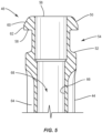
FIG. 5 is an enlarged, cross sectional side view of a portion of the component shown inFIG. 2 ; -
FIG. 6 is a side view of one embodiment of a component of the surgical system shown inFIG. 1 in accordance with the principles of the present disclosure; -
FIG. 7 is a side, cross sectional view of the component shown inFIG. 6 ; -
FIG. 8 is an enlarged side view of a portion of the component shown inFIG. 6 ; -
FIG. 9 is an enlarged side view of a portion of the components of the surgical system shown inFIG. 1 , with the components in an unassembled configuration; -
FIG. 10 an enlarged, cross sectional side view of a portion of components of the surgical system shown inFIG. 1 , with the components in an unassembled configuration; -
FIG. 11 is an enlarged, cross sectional side view of a portion of the surgical system shown inFIG. 1 , with the components in an unassembled configuration; -
FIG. 12 is an enlarged side view of a portion of components of the surgical system shown inFIG. 1 , with the components in an assembled configuration; -
FIG. 13 is an enlarged, cross sectional side view of a portion of components of the surgical system shown inFIG. 1 , with the components in an assembled configuration; -
FIG. 14 is a plan view of one embodiment of the surgical system shown inFIG. 1 in accordance with the principles of the present disclosure; -
FIG. 15 is a plan view of one embodiment of the surgical system shown inFIG. 1 in accordance with the principles of the present disclosure; -
FIG. 16 is a plan view of one embodiment of the surgical system shown inFIG. 1 in accordance with the principles of the present disclosure; -
FIG. 17 is a side view of components of one embodiment of a surgical system in accordance with the principles of the present disclosure; -
FIG. 18 is a side view of one embodiment of a component of the surgical system shown inFIG. 17 in accordance with the principles of the present disclosure; -
FIG. 19 is a side, cross sectional view of the component shown inFIG. 18 ; -
FIG. 20 is an enlarged side view of a portion of the component shown inFIG. 18 ; and -
FIG. 21 is an enlarged, cross sectional side view of a portion of the component shown inFIG. 18 . - The embodiments of the surgical system and related methods (not claimed) of use disclosed are discussed in terms of medical devices for the treatment of musculoskeletal disorders and more particularly, in terms of a delivery system and a method for treating a spine. In some embodiments, the systems and methods (not claimed) of the present disclosure comprise medical devices including surgical instruments and implants that are employed with a surgical treatment, as described herein, for example, with a cervical, thoracic, lumbar and/or sacral region of a spine.
- A cement delivery gun creates back pressure when used in connection with a predicate bone filler device. A current fenestrated screw system relies on an extra instrument to counteract the back pressure generated by the cement delivery system gun. On the other hand, in various embodiments, the delivery system of the present disclosure simplifies the procedure by removing unnecessary steps while still providing the function needed. In some embodiments, the present delivery system eliminates the need for a separate instrument to secure a bone filler device to its guide/driver and includes a handle having a specific shape developed to retain proper connection between the handle and the guide/driver during cement application. In some embodiments, the handle includes wings having a shape that allows both easy attachment to an undercut in the guide/driver. The handle also provides an ergonomic feature that allows simple release the bone filler device from the guide/driver. In some embodiments, a distal end of the handle having a conical shape that helps facilitate axilization of the bone filler device ensuring proper assembly of the handle with the guide/driver by aligning the handle with the guide/driver. In some embodiments, the handle and/or guide/drive will create clicking during assembly of the handle with the guide/driver to indicate that the handle has been properly assembled with the guide/driver.
- In some embodiments, the delivery system of the present disclosure may be employed to treat spinal disorders such as, for example, degenerative disc disease, disc herniation, osteoporosis, spondylolisthesis, stenosis, scoliosis, kyphosis, and other curvature abnormalities, tumor and fractures. In some embodiments, the delivery system of the present disclosure may be employed with other osteal and bone related applications, including those associated with diagnostics and therapeutics. In some embodiments, the disclosed delivery system may be alternatively employed in a surgical treatment with a patient in a prone or supine position, and/or employ various surgical approaches to the spine, including anterior, posterior, posterior mid-line, direct lateral, postero-lateral, and/or antero-lateral approaches, and in other body regions. The delivery system of the present disclosure may also be alternatively employed with procedures for treating the lumbar, cervical, thoracic, sacral and pelvic regions of a spinal column. The delivery system of the present disclosure may also be used on animals, bone models and other non-living substrates, such as, for example, in training, testing and demonstration.
- The following discussion includes a description of a delivery system and related components and methods (not claimed) of employing the delivery system in accordance with the principles of the present disclosure. Alternate embodiments are also disclosed. Reference is made in detail to the exemplary embodiments of the present disclosure, which are illustrated in the accompanying figures. Turning to
FIGS. 1-21 , there are illustrated components of a delivery system, such as, adelivery system 30. - The components of
delivery system 30 can be fabricated from biologically acceptable materials suitable for medical applications, including metals, synthetic polymers, ceramics and bone material and/or their composites. For example, the components of delivery system 30, individually or collectively, can be fabricated from materials such as stainless steel alloys, aluminum, commercially pure titanium, titanium alloys, Grade 5 titanium, super-elastic titanium alloys, cobalt-chrome alloys, superelastic metallic alloys (e.g., Nitinol, super elasto-plastic metals, such as GUM METAL®), ceramics and composites thereof such as calcium phosphate (e.g., SKELITE™), thermoplastics such as polyaryletherketone (PAEK) including polyetheretherketone (PEEK), polyetherketoneketone (PEKK) and polyetherketone (PEK), carbon-PEEK composites, PEEK-BaSO4 polymeric rubbers, polyethylene terephthalate (PET), fabric, silicone, polyurethane, silicone-polyurethane copolymers, polymeric rubbers, polyolefin rubbers, hydrogels, semi-rigid and rigid materials, elastomers, rubbers, thermoplastic elastomers, thermoset elastomers, elastomeric composites, rigid polymers including polyphenylene, polyamide, polyimide, polyetherimide, polyethylene, epoxy, bone material including autograft, allograft, xenograft or transgenic cortical and/or corticocancellous bone, and tissue growth or differentiation factors, partially resorbable materials, such as, for example, composites of metals and calcium-based ceramics, composites of PEEK and calcium based ceramics, composites of PEEK with resorbable polymers, totally resorbable materials, such as, for example, calcium based ceramics such as calcium phosphate, tri-calcium phosphate (TCP), hydroxyapatite (HA)-TCP, calcium sulfate, or other resorbable polymers such as polyaetide, polyglycolide, polytyrosine carbonate, polycaroplaetohe and their combinations. - Various components of
delivery system 30 may have material composites, including the above materials, to achieve various desired characteristics such as strength, rigidity, elasticity, compliance, biomechanical performance, durability and radiolucency or imaging preference. The components ofdelivery system 30, individually or collectively, may also be fabricated from a heterogeneous material such as a combination of two or more of the above-described materials. The components ofdelivery system 30 may be monolithically formed, integrally connected or include fastening elements and/or instruments, as described herein. -
Delivery system 30 is employed, for example, with a fully open surgical procedure, a minimally invasive procedure including percutaneous techniques, and mini-open surgical techniques to deliver and introduce instrumentation and/or a spinal implant, such as, for example, a bone fastener, at a surgical site of a patient, which includes, for example, a spine. In some embodiments, the spinal implant can include one or more components of one or more spinal constructs, such as, for example, interbody devices, interbody cages, bone fasteners, spinal rods, tethers, connectors, plates and/or bone graft, and can be employed with various surgical procedures including surgical treatment of a cervical, thoracic, lumbar and/or sacral region of a spine. -
Delivery system 30 includes a first instrument, such as, for example, adriver 32.Driver 32 includes a sleeve, such as, anouter sleeve 34 that extends along a longitudinal axis L1 between anend 36 and anopposite end 38.Sleeve 34 has aninner surface 40 defining apassageway 42, as best shown inFIG. 3 .Passageway 42 is coaxial with axis L1 and extends the entire length ofsleeve 34 such thatpassageway 42 extends through opposite end surfaces ofends passageway 42 has a circular diameter. In some embodiments,passageway 42 has a uniform diameter along the entire length ofpassageway 42. In some embodiments,passageway 42 may be disposed at alternate orientations, relative to axis L1, such as, for example, transverse, perpendicular and/or other angular orientations such as acute or obtuse, co-axial and/or may be offset or staggered. In some embodiments,passageway 42 may have various cross section configurations, such as, for example, oval, oblong, triangular, rectangular, square, polygonal, irregular, uniform, non-uniform, variable, tubular and/or tapered. -
Driver 32 includes a sleeve, such as, for example, aninner sleeve 44 rotatably disposed inpassageway 42 such thatsleeve 44 is coaxial with axis L1.Sleeve 44 extends between anend 46 and anopposite end 48 that is disposed inpassageway 42.End 46 includes a first mating element, such as, for example, aflange 50 that is spaced apart from aflange 52 by an undercut, such as, for example, arecess 54.Flange 50 includesopposite surfaces surfaces FIGS. 4 and5 .Surface 56 defines the end surface ofend 46.Surface 60 extends transverse to axis L1 andsurface 62 extends parallel to axis L1. -
Sleeve 44 includes abody 64 having aninner surface 66 that defines achannel 68, as best shown inFIG. 3 .Channel 68 is coaxial with axis L1 and extends the entire length ofsleeve 44 such thatchannel 68 extends throughsurface 56 and an opposite end surface ofend 48. In some embodiments,channel 68 has a circular diameter. In some embodiments,channel 68 has a uniform diameter along the entire length ofchannel 68. In some embodiments,channel 68 may be disposed at alternate orientations, relative to axis L1, such as, for example, transverse, perpendicular and/or other angular orientations such as acute or obtuse, co-axial and/or may be offset or staggered. In some embodiments,channel 68 may have various cross section configurations, such as, for example, oval, oblong, triangular, rectangular, square, polygonal, irregular, uniform, non-uniform, variable, tubular and/or tapered. -
End 48 includes atip 70 that is connected withbody 64, as best shown inFIG. 3 . In some embodiments,tip 70 is removably connected withbody 64 such thattip 70 is disposable. In such embodiments,tip 70 may be provisionally fixed withbody 64 such that rotation ofbody 64 also rotatestip 70. In some embodiments,tip 70 is variously connected withbody 64, such as, for example, frictional engagement, threaded engagement, mutual grooves, screws, adhesive, nails, barbs and/or raised element. In some embodiments,tip 70 is integrally and/or monolithically formed withbody 64 such thattip 70 cannot be removed frombody 64 without breakingbody 64 and/ortip 70.Tip 70 extends between anend 72 and anopposite end 74.Tip 70 includes aninner surface 76 defining abore 78 that is coaxial with axis L1 and extends the entire length oftip 70 such that bore 78 extends through opposite end surfaces ofends bore 78. In some embodiments, bore 78 may be disposed at alternate orientations, relative to axis L1, such as, for example, transverse, perpendicular and/or other angular orientations such as acute or obtuse, co-axial and/or may be offset or staggered. In some embodiments, bore 78 may have various cross section configurations, such as, for example, oval, oblong, triangular, rectangular, square, polygonal, irregular, uniform, non-uniform, variable, tubular and/or tapered.End 72 is positioned inchannel 68 such that bore 78 is in communication and coaxial withchannel 68.End 74 defines a drive portion configured for engagement with an implant, such as, for example, abone fastener 80, as discussed herein. In some embodiments, the drive portion may include a square, triangular, polygonal, star or hexalobe cross sectional configuration configured engage a correspondingly shaped portion offastener 80. In some embodiments,tip 70 includes a threaded outer surface that is configured to engage threads offastener 80 to couplesleeve 44 tofastener 80, as discussed herein. -
Fastener 80 includes a head, such as, for example, animplant receiver 84 and ascrew shaft 86 that is coupled toreceiver 84.Implant receiver 84 extends parallel to axis L1 whenfastener 80 is coupled tosleeve 44.Implant receiver 84 includes a pair of spaced apartarms implant cavity 92 therebetween configured for disposal of a spinal construct, such as, for example, a spinal rod.Arms fastener 80 is coupled tosleeve 44. In some embodiments,arm 88 and/orarm 90 may be disposed at alternate orientations, relative to axis L1, such as, for example, transverse, perpendicular and/or other angular orientations such as acute or obtuse, coaxial and/or may be offset or staggered.Arms arms tensioning bone fastener 80. -
Arm 88 includes a break awaytab 94 that is frangibly connected to arm 88 (FIG. 3 ) such that manipulation oftab 94 relative toarm 88 can fracture andseparate tab 94 fromarm 88 at a predetermined force and/or torque limit, as described herein. In some embodiments, as force and/or torque is applied totab 94 and resistance increases, for example, the predetermined torque and force limit is approached.Arm 90 includes a break awaytab 96 that is frangibly connected toarm 90 such that manipulation oftab 96 relative toarm 90 can fracture andseparate tab 96 fromarm 90 at a predetermined force and/or torque limit, as described herein. In some embodiments, as force and/or torque is applied totab 96 and resistance increases, for example, the predetermined torque and force limit is approached. - In some embodiments,
tabs tabs arms tabs arms -
Cavity 92 is substantially U-shaped. In some embodiments, all or only a portion ofcavity 92 may have alternate cross section configurations, such as, for example, closed, V-shaped, W-shaped, oval, oblong triangular, square, polygonal, irregular, uniform, non-uniform, offset, staggered, and/or tapered.Implant receiver 84 includes thread forms configured for engagement with a coupling member, such as, for example, a setscrew to retain a spinal rod withincavity 92. The thread forms ofimplant receiver 84 may also engage threadedouter surface 82 oftip 70 to couplesleeve 44 to implantreceiver 84, as discussed herein. In some embodiments, the inner surface ofimplant receiver 84 may be disposed with the coupling member and/ortip 70 in alternate fixation configurations, such as, for example, friction fit, pressure fit, locking protrusion/recess, locking keyway and/or adhesive. In some embodiments, all or only a portion of the inner surface ofimplant receiver 84 may have alternate surface configurations to enhance engagement with a spinal rod, a setscrew and/ortip 70, such as, for example, rough, arcuate, undulating, mesh, porous, semi-porous, dimpled and/or textured. In some embodiments,implant receiver 92 may include alternate configurations, such as, for example, closed, open and/or side access. In some embodiments,bone fastener 80 includes acrown 98 configured to facilitate positioning of a spinal rod. -
Implant receiver 84 defines acavity 100 configured for disposal of a head ofscrew shaft 86, as described herein.Screw shaft 86 includes a socket, such as, for example, atool engaging portion 102 configured to engage the drive portion ofend 74.Screw shaft 86 includes an outer surface having an external thread form. In some embodiments, the external thread form may include a single thread turn or a plurality of discrete threads.Screw shaft 86 includes aninner surface 104 defining abore 106 that extends the entire length ofscrew shaft 86. When the drive portion ofend 74 engagestool engaging portion 102, bore 78 is in communication and coaxial withbore 106. In some embodiments, screwshaft 86 includes one or a plurality of openings that each extend throughsurface 104 and an oppositeouter surface 108 ofscrew shaft 86 such that a material, such as, for example, bone cement disposed inbore 106 can exit bore 106 through one of the openings that extend throughsurfaces opening 110 in a distal end ofscrew shaft 86 that is coaxial with axis L1 whenfastener 80 is coupled tosleeve 44. - In some embodiments,
implant receiver 84 is manually engageable withscrew shaft 86 in a non-instrumented assembly, as described herein. In some embodiments, manual engagement and/or non-instrumented assembly ofimplant receiver 84 andscrew shaft 86 includes coupling without use of separate and/or independent instrumentation engaged with the components to effect assembly. In some embodiments, manual engagement and/or non-instrumented assembly includes a practitioner, surgeon and/or medical staff graspingimplant receiver 84 andscrew shaft 86 and forcibly assembling the components. In some embodiments, manual engagement and/or non-instrumented assembly includes a practitioner, surgeon and/or medical staff graspingimplant receiver 84 andscrew shaft 86 and forcibly snap fitting the components together, as described herein. In some embodiments, manual engagement and/or non-instrumented assembly includes a practitioner, surgeon and/or medical staff graspingimplant receiver 84 andscrew shaft 86 and forcibly pop fitting the components together and/or popfitting implant receiver 84 ontoscrew shaft 86, as described herein. In some embodiments, a force in a range of 2-50 N is required to manually engageimplant receiver 84 andscrew shaft 86 and forcibly assemble the components. In some embodiments, a force in a range of 5-10 N is required to manually engageimplant receiver 84 andscrew shaft 86 and forcibly assemble the components. - In some embodiments,
implant receiver 84 is connectable withscrew shaft 86 such thatscrew shaft 86 is pivotable and/or rotatable relative to implantreceiver 84 in a plurality of planes. In some embodiments,implant receiver 84 is connectable withscrew shaft 86 to include various configurations, such as, for example, a posted screw, a pedicle screw, a bolt, a bone screw for a lateral plate, an interbody screw, a uni-axial screw (UAS), a fixed angle screw (FAS), a multi-axial screw (MAS), a side loading screw, a sagittal adjusting screw (SAS), a transverse sagittal adjusting screw (TSAS), an awl tip (ATS), a dual rod multi-axial screw (DRMAS), midline lumbar fusion screw and/or a sacral bone screw. - To connect
driver 32 withfastener 80,tip 70 is inserted intoimplant cavity 92 andsleeve 44 is rotated relative tosleeve 34 such that the threads onouter surface 82 oftip 70 mate with the thread forms ofimplant receiver 84 to couplesleeve 44 withreceiver 84.Sleeve 44 is further rotated relative tosleeve 34 such that the drive portion ofend 74 is positioned intool engaging portion 102 to couplesleeve 44 withscrew 86. In some embodiments, the threads onouter surface 82 oftip 70 mate with the thread forms ofimplant receiver 84 at the same time that the drive portion ofend 74 is positioned intool engaging portion 86 to positionreceiver 84 relative to screw 86 such thatreceiver 84 and screw 86 extend parallel to axis L1 and maintain such positioning asfastener 80 is driven into bone or othertissue using driver 32, as discussed herein. That is, mating the threads onouter surface 82 oftip 70 with the thread forms ofimplant receiver 84 at the same time that the drive portion ofend 74 is positioned intool engaging portion 86 preventsreceiver 84 from pivoting relative to screw 86. -
Delivery system 30 includes a second instrument, such as, for example, abone filler device 112.Device 112 includes ashaft 114 and ahandle 116 that is coupled toshaft 114. In some embodiments, handle 116 is permanently fixed toshaft 114 such that handle 116 cannot be removed fromshaft 114 without breakinghandle 116 and/orshaft 114. In some embodiments, handle 116 is integrally and/or monolithically formed withshaft 114. In some embodiments, handle 116 is removably connected withshaft 114 such that handle 116 can be removed fromshaft 114 without breakinghandle 116 and/orshaft 114. -
Shaft 114 is configured for disposal inchannel 68 and extends along a longitudinal axis L2 between anend 118 and anopposite end 120. Handle 116 is connected withend 118. In some embodiments,shaft 114 is tapered fromend 118 to end 120 such thatend 118 has a minimum diameter that is greater than a minimum diameter ofend 120. In some embodiments,shaft 114 has a uniform diameter along the entire length ofshaft 114.Shaft 114 comprises aninner surface 122 that defines alumen 124, as best shown inFIG. 7 .Lumen 124 is coaxial with axis L2 and extends the entire length ofshaft 114 such thatlumen 124 extends through opposite end surfaces ofends lumen 124 has a circular diameter. In some embodiments,lumen 124 has a diameter that tapers along the length ofshaft 114. In some embodiments,lumen 124 may be disposed at alternate orientations, relative to axis L2, such as, for example, transverse, perpendicular and/or other angular orientations such as acute or obtuse, co-axial and/or may be offset or staggered. In some embodiments,lumen 124 may have various cross section configurations, such as, for example, oval, oblong, triangular, rectangular, square, polygonal, irregular, uniform, non-uniform, variable, tubular and/or tapered. - Handle 116 comprises a
body 126 including acylindrical portion 128 that is coaxial withshaft 114 and axis L2.Cylindrical portion 128 has a threadedouter surface 130 and an oppositeinner surface 132 defining anopening 134 that is in communication and coaxial withlumen 124, as best shown inFIG. 7 .Body 126 comprises aconical portion 136 oppositecylindrical portion 128.Conical portion 136 is configured for disposal inchannel 68 to connect handle 116 withsleeve 44, as discussed herein.Conical portion 136 helps facilitate axialization ofdevice 112 relative todriver 32 to ensure proper assembly. - Handle 116 comprises a second mating element that includes a
first wing 138 that extends from afirst side 140 ofbody 126 in a cantilevered configuration and asecond wing 142 that extends from an oppositesecond side 144 ofbody 126 in a cantilevered configuration.Wing 138 comprises anextension 146 that extends fromfirst side 140, a grippingportion 148 that extends fromextension 146 and atab 150 that extends fromextension 146.Wing 142 comprises anextension 152 that extends fromsecond side 144, a grippingportion 154 that extends fromextension 152 and atab 156 that extends fromextension 152. Extensions 146,152 each extend parallel to axis L2. Grippingportions Tabs Tab 150 includes asurface 150a that extends parallel to axis L2 andtab 156 includes asurface 156a that extends parallel to axis L2.Surface 150a facessurface 156a.Tab 150 includes asurface 150b that extends perpendicular to axis L2 andtab 156 includes asurface 156b that extends perpendicular to axis L2.Tabs flange 50 to secure thedevice 112 todriver 32 such thatdevice 112 is prevented from translating axially relative todriver 32 in the direction shown by arrow A inFIG. 12 .Surface 150a is spaced a first distance apart fromsurface 156a when no forces are applied towings Wings body 126. For example, a force may be applied to grippingportion 148 to move grippingportion 148 relative tobody 126 in the direction shown by arrow B inFIG. 8 and a force may be applied to grippingportion 154 to move grippingportion 154 relative tobody 126 in the direction shown by arrow C inFIG. 8 such thattabs surface 150a is spaced an increased second distance apart fromsurface 156a. In some embodiments,wings portions tabs surface 150a is spaced the first distance apart fromsurface 156a. - To connect
device 112 withsleeve 44,shaft 114 is inserted intochannel 68 such that axis L2 is coaxial with axis L1.Device 112 is then translated axially relative tosleeve 44 in the direction shown by arrow D inFIG. 9 untilconical portion 136 is positioned withinchannel 68. Asdevice 112 translates axially relative tosleeve 44 in the direction shown by arrow D inFIG. 9 ,surface 150a oftab 150 slides alongsurface 60 offlange 50, as shown inFIG. 11 andsurface 156a oftab 156 slides alongsurface 60. Assurfaces surface 60,wings body 126 such that the distance betweensurfaces Device 112 is further translated axially relative tosleeve 44 in the direction shown by arrow D inFIG. 9 whensurfaces surfaces surface 62 offlange 50.Device 112 is further translated axially relative tosleeve 44 in the direction shown by arrow D inFIG. 9 such thattabs recess 54. The inward bias ofwings tabs surface 150a is spaced the first distance apart fromsurface 156a and surfaces 150b, 156b engagesurface 58 offlange 50, as shown inFIGS. 12 and13 , to preventdevice 112 from translating axially relative tosleeve 44 in the direction shown by arrow A inFIG. 12 . In some embodiments,tabs tabs surface 58 offlange 50, which indicates thedevice 112 is properly assembled withsleeve 44. - To remove
device 112 fromsleeve 44, a force is applied to grippingportion 148 to move grippingportion 148 relative tobody 126 in the direction shown by arrow B inFIG. 8 and a force is applied to grippingportion 154 to move grippingportion 154 relative tobody 126 in the direction shown by arrow C inFIG. 8 such thatsurface 150a is spaced the second distance apart fromsurface 156a.Device 112 is translated axially relative tosleeve 44 in the direction shown by arrow A inFIG. 12 such thatsurfaces surface 62.Device 112 may be translated axially relative tosleeve 44 in the direction shown by arrow A inFIG. 12 untilshaft 114 is removed fromchannel 68. - In assembly, operation and use,
driver 32 is connected withfastener 80 as discussed herein. Access to the surgical site is obtained and the particular surgical procedure is performed. The components ofdelivery system 30 are employed to augment the surgical treatment. For example,fastener 80 may be inserted into bone or other tissue withdriver 32, for example via clockwise or counterclockwise rotation ofsleeve 44 relative tosleeve 34.Device 112 is connected withdriver 32 either before or afterfastener 80 is inserted into bone or other tissue. - In one embodiment, shown in
FIGS. 14 and15 , bone filler material, such as, for example, bone cement is inserted throughopening 134 and intolumen 124. The bone filler material may be inserted intolumen 124 before or afterdevice 112 is connected withdriver 32. Aplunger 158 is aligned withopening 134, as shown inFIG. 14 .Plunger 158 is then translated relative to handle 116 in the direction shown by arrow E inFIG. 15 such thatplunger 158 pushes the bone filler material throughlumen 124 and bores 78, 106 and the bone filler material exits screw 86 via one or more openings inscrew 86. As the bone filler material cures, it will bond screw 86 with bone or other tissue. Upon completion of a surgical procedure,plunger 158 may be removed fromdevice 112, anddriver 32 is removed from the surgical site. In some embodiments,device 112 is disengaged fromdriver 32 either before or afterdriver 32 is removed from the surgical site. In some embodiments, a spinal construct, such as, for example, a spinal rod is inserted intoimplant cavity 92 afterdriver 32 is removed from the surgical site and a setscrew is engaged withreceiver 84 such that threads on an outer surface of the setscrew engage the threads on the inner surfaces ofarms receiver 84 until the setscrew engages the rod to fix the rod relative toreceiver 84. - In one embodiment, shown in
FIG. 16 ,delivery system 30 includes acement delivery system 160 having acartridge 162 that is connected to handle 112 by a luer lock 164 and acement delivery gun 166 that is connected tocartridge 162. Threads of luer lock 164 are mated with threads ofsurface 130 to connectcartridge 162 to handle 112.Cartridge 162 is loaded with a bone filler material, such as, for example, bone cement either before or aftercartridge 162 is connected to handle 112. An actuator, such as, for example, a trigger handle ofcement delivery gun 166 is activated to move the bone filler material throughlumen 124 and bores 78, 106 such that the bone filler material exits screw 86 via one or more openings inscrew 86. Engagement ofsurfaces device 112 from translating axially relative tosleeve 44 in the direction shown by arrow A inFIG. 12 due to back pressure generated bycement delivery gun 166. As the bone filler material cures, it will bond screw 86 with bone or other tissue. Upon completion of a surgical procedure,cement delivery system 160 may be removed fromdevice 112, anddriver 32 is removed from the surgical site. In some embodiments,device 112 is disengaged and/or disconnected fromdriver 32 either before or afterdriver 32 is removed from the surgical site. In some embodiments, a spinal construct, such as, for example, a spinal rod is inserted intoimplant cavity 92 afterdriver 32 is removed from the surgical site and a setscrew is engaged withreceiver 84 such that threads on an outer surface of the setscrew engage the threads on the inner surfaces ofarms receiver 84 until the setscrew engages the rod to fix the rod relative toreceiver 84. -
Delivery system 30 can include one or a plurality of bone fasteners such as those described herein and/or fixation elements, which may be employed with a single vertebral level or a plurality of vertebral levels. In some embodiments, the bone fasteners may be engaged with vertebrae in various orientations, such as, for example, series, parallel, offset, staggered and/or alternate vertebral levels. In some embodiments, the bone fasteners and/or fixation elements may include one or a plurality of multi-axial screws, sagittal angulation screws, pedicle screws, mono-axial screws, uni-planar screws, fixed screws, tissue penetrating screws, conventional screws, expanding screws, wedges, anchors, buttons, clips, snaps, friction fittings, compressive fittings, expanding rivets, staples, nails, adhesives, posts, fixation plates and/or posts. In some embodiments,system 30 may comprise various instruments including the configuration of the present disclosure, such as, for example, inserters, extenders, reducers, spreaders, distractors, blades, retractors, clamps, forceps, elevators and drills, which may be alternately sized and dimensioned, and arranged as a kit, according to the requirements of a particular application. - In some embodiments,
delivery system 30 includes an agent, which may be disposed, packed, coated or layered within, on or about the components and/or surfaces ofdelivery system 30. In some embodiments, the agent may include bone growth promoting material, such as, for example, bone graft to enhance fixation of the fixation elements with vertebrae. The components ofdelivery system 30 can be made of radiolucent materials such as polymers. Radiomarkers may be included for identification under x-ray, fluoroscopy, CT or other imaging techniques. In some embodiments, the agent may include one or a plurality of therapeutic agents and/or pharmacological agents for release, including sustained release, to treat, for example, pain, inflammation and degeneration. - In one embodiment, shown in
FIGS. 17-21 ,delivery system 30 includes adriver 168 that is similar todriver 32.Driver 168 includes anouter sleeve 170 having alower portion 172 and anupper portion 174 that is connected withlower portion 172.Lower portion 172 extends along a longitudinal axis L3 between anend 176 and anopposite end 178.End 176 includes acircumferential cutout 180 configured for disposal of anend 182 ofupper portion 174 to connectupper portion 174 withlower portion 172. In some embodiments,upper portion 174 is connected withlower portion 172 to provisionally fixupper portion 174 relative tolower portion 172 such that rotation ofupper portion 174 about axis L3 also rotateslower portion 172 about axis L3. In some embodiments,upper portion 174 can be variously connected withlower portion 172, such as, for example, monolithic, integral connection, frictional engagement, threaded engagement, mutual grooves, screws, adhesive, nails, barbs and/or raised element.End 178 includes atip 184 defining a drive portion configured for engagement with an implant, such as, for example,bone fastener 80, as discussed herein. In some embodiments, the drive portion may include a square, triangular, polygonal, star or hexalobe cross sectional configuration configured engage a correspondingly shaped portiontool engaging portion 102 offastener 80. -
Upper portion 174 includes anend 186opposite end 182.End 186 includes a first mating element, such as, for example, aflange 188 that is similar toflange 50.Flange 188 is spaced apart from aflange 190 by an undercut, such as, for example, arecess 192.Flange 188 includesopposite surfaces surfaces FIGS. 20 and21 .Surface 194 defines an end surface ofend 186.Surface 198 extends transverse to axis L3 andsurface 200 extends parallel to axis L3. -
Lower portion 172 includes aninner surface 202 defining apassageway 204 andupper portion 174 includes aninner surface 206 defining achannel 208 that is in communication and coaxial withpassageway 204.Passageway 204 andchannel 208 are configured for disposal of aninner sleeve 210 such thatsleeve 210 is rotatable relative tosleeve 170 about axis L3.Sleeve 210 includes anend 212 and anopposite end 214 having a threadedouter surface 228. A distal portion ofend 212 is positioned inpassageway 204 and aproximal portion 216 ofend 212 is positioned inchannel 208.Proximal portion 216 includes aninner surface 218 defining asocket 220. In some embodiments,socket 220 may include a square, triangular, polygonal, star or hexalobe cross sectional configuration configured engage a correspondingly shaped portion of athumbwheel 222, as discussed herein. -
Upper portion 174 includes awindow 224 that is configured to allow visualization of a portion ofdevice 112 and awindow 226 that is configured to allow grasping ofthumbwheel 222.Thumbwheel 222 includes a bit (not shown) disposed insocket 220. The bit has a shape that corresponds to the shape ofsocket 220 such that rotation ofthumbwheel 222 relative tosleeve 170 about axis L3 also rotatessleeve 210 relative tosleeve 170 about axis L3. - To connect
driver 168 withfastener 80,thumbwheel 222 is rotated relative tosleeve 170 about axis L3 in a first rotational direction, such as, for example clockwise or counterclockwise. Rotation ofthumbwheel 222 relative tosleeve 170 about axis L3 in the first rotational direction causes rotation ofsleeve 210 relative tosleeve 170 about axis L3 in the first rotational direction. Assleeve 210 rotates relative tosleeve 170 about axis L3 in the first rotational direction, the threads onsurface 228 ofsleeve 210 mate with the threads on the inner surfaces ofarms fastener 80. Further rotation ofsleeve 210 relative tosleeve 170 about axis L3 in the first rotational direction causessleeve 210 to translate axially relative tosleeve 170 in the direction shown by arrow F inFIG. 19 . Assleeve 210 translates axially relative tosleeve 170 in the direction shown by arrow F inFIG. 19 ,tip 184 is inserted intotool engaging portion 102 ofscrew 86. Simultaneous engagement oftip 184 withtool engaging portion 102 and the threads onsurface 228 ofsleeve 210 with the threads on the inner surfaces ofarms fastener 80 preventsscrew 86 from pivoting relative toreceiver 84. - To remove
driver 168 fromfastener 80,thumbwheel 222 is rotated relative tosleeve 170 about axis L3 in an opposite second rotational direction, such as, for example clockwise or counterclockwise. Rotation ofthumbwheel 222 relative tosleeve 170 about axis L3 in the second rotational direction causes rotation ofsleeve 210 relative tosleeve 170 about axis L3 in the second rotational direction. Assleeve 210 rotates relative tosleeve 170 about axis L3 in the second rotational direction,sleeve 210 translates axially relative tosleeve 170 in the direction shown by arrow G inFIG. 19 . Assleeve 210 translates axially relative tosleeve 170 in the direction shown by arrow G inFIG. 19 ,tip 184 moves out oftool engaging portion 102 ofscrew 86 and the threads onsurface 228 ofsleeve 210 disengage the threads on the inner surfaces ofarms fastener 80, at whichpoint driver 168 can be fully removed fromfastener 80. - In assembly, operation and use,
driver 168 is connected withfastener 80 as discussed herein. Access to the surgical site is obtained and the particular surgical procedure is performed. The components ofdelivery system 30 are employed to augment the surgical treatment. For example,fastener 80 may be inserted into bone or other tissue withdriver 168, for example via clockwise or counterclockwise rotation ofsleeve 170. -
Device 112 is connected withdriver 168 either before or afterfastener 80 is inserted into bone or other tissue. To connectdevice 112 withdriver 168,shaft 114 is inserted intochannel 208 such that axis L3 is coaxial with axis L1.Device 112 is then translated axially relative tosleeve 170 in the direction shown by arrow F inFIG. 19 untilshaft 114 extends throughthumbwheel 222 andconical portion 136 is positioned withinchannel 208. Asdevice 112 translates axially relative tosleeve 170 in the direction shown by arrow F inFIG. 19 ,surface 150a oftab 150 slides alongsurface 198 offlange 188 andsurface 156a oftab 156 slides alongsurface 198. Assurfaces surface 198,wings body 126 such that the distance betweensurfaces Device 112 is further translated axially relative tosleeve 170 in the direction shown by arrow F inFIG. 19 whensurfaces surfaces surface 200 offlange 188.Device 112 is further translated axially relative tosleeve 170 in the direction shown by arrow F inFIG. 19 such thattabs recess 198. The inward bias ofwings tabs surface 150a is spaced the first distance apart fromsurface 156a and surfaces 150b, 156b engagesurface 196 offlange 188, as shown inFIG. 17 to preventdevice 112 from translating axially relative tosleeve 170 in the direction shown by arrow G inFIG. 19 . In some embodiments,tabs tabs surface 196 offlange 188, which indicates thedevice 112 is properly assembled withsleeve 170. - In one embodiment, bone filler material, such as, for example, bone cement is inserted through
opening 134 and intolumen 124. The bone filler material may be inserted intolumen 124 afterdevice 112 is connected withdriver 168.Plunger 158 is aligned withopening 134.Plunger 158 is then translated relative to handle 116 in the direction shown by arrow F inFIG. 19 such thatplunger 158 pushes the bone filler material throughlumen 124, anaperture 230 that extends throughtip 184 and bore 106 such that the bone filler material exits screw 86 via one or more openings inscrew 86. As the bone filler material cures, it will bond screw 86 with bone or other tissue. Upon completion of a surgical procedure,plunger 158 may be removed fromdevice 112, anddriver 168 is removed from the surgical site. In some embodiments,device 112 is disengaged fromdriver 168 either before or afterdriver 168 is removed from the surgical site. To removedevice 112 fromsleeve 170, a force is applied to grippingportion 148 to move grippingportion 148 relative tobody 126 in the direction shown by arrow B inFIG. 8 and a force is applied to grippingportion 154 to move grippingportion 154 relative tobody 126 in the direction shown by arrow C inFIG. 8 such thatsurface 150a is spaced the second distance apart fromsurface 156a.Device 112 is translated axially relative tosleeve 170 in the direction shown by arrow F inFIG. 19 such thatsurfaces surface 200.Device 112 may be translated axially relative tosleeve 170 in the direction shown by arrow F inFIG. 19 untilshaft 114 is removed fromchannel 208. In some embodiments, a spinal construct, such as, for example, a spinal rod is inserted intoimplant cavity 92 afterdriver 168 is removed from the surgical site and a setscrew is engaged withreceiver 84 such that threads on an outer surface of the setscrew engage the threads on the inner surfaces ofarms receiver 84 until the setscrew engages the rod such that the rod is fixed relative toreceiver 84. - In one embodiment, threads of luer lock 164 are mated with threads of
surface 130 to connectcartridge 162 to handle 112.Cartridge 162 is loaded with a bone filler material, such as, for example, bone cement either before or aftercartridge 162 is connected to handle 112. The trigger handle ofcement delivery gun 166 is activated to move the bone filler material throughlumen 124,aperture 230 and bore 106 such that the bone filler material exits screw 86 via one or more openings inscrew 86. As the bone filler material cures, it will bond screw 86 with bone or other tissue. Upon completion of a surgical procedure,cement delivery system 160 may be removed fromdevice 112, anddriver 168 is removed from the surgical site. In some embodiments,device 112 is disengaged fromdriver 168 either before or afterdriver 168 is removed from the surgical site. In some embodiments, a spinal construct, such as, for example, a spinal rod is inserted intoimplant cavity 92 afterdriver 168 is removed from the surgical site and a setscrew is engaged withreceiver 84 such that threads on an outer surface of the setscrew engage the threads on the inner surfaces ofarms receiver 84 until the setscrew engages the rod such that the rod is fixed relative toreceiver 84. - It will be understood that various modifications may be made to the embodiments disclosed herein. Therefore, the above description should not be construed as limiting, but merely as exemplification of the various embodiments.
Claims (8)
- A delivery system (30) for treating spine disorders comprising:a first instrument (32, 168) comprising an outer sleeve (34, 170) that extends along a longitudinal axis (L1, L3) defining a passageway (42, 204), and an inner sleeve (44, 210) coaxial with the axis (L1, L3) having a first end (48, 212) disposed in the passageway (42, 204) and a second end (46, 214) including a first mating element (50, 188), the inner sleeve (44) defining a channel (68) coaxial with the axis (L1) and extends the entire length of the inner sleeve (44); anda second instrument (112) comprising a hollow shaft (114) disposed in the channel (48) and extends along a longitudinal axis (L2) and a handle (116) coupled to the shaft (114), the handle (116) comprising a body (126) that is coaxial with the shaft (114) and the axis (L2), and a second mating element (138, 142) extending from the body (126), the second mating element (138, 142) being configured to engage the first mating element (50) to secure the second instrument (112) to the first instrument (32) such that the axis (L2) is coaxial with the axis (L1, L3),wherein the second mating element (138, 142) includes a first wing (138) that extends from a first side (140) of the body (126) in a cantilevered configuration, and a second wing (142) that extends from an opposite second side (144) of the body (126) in a cantilevered configuration;wherein the first wing (138) comprises a first extension (146) that extends parallel to the longitudinal axis (L2) from the first side (140), a first gripping portion (148) that extends transverse to the longitudinal axis (L2) from the first extension (146) and a first tab (150) that extends perpendicular to the longitudinal axis (L2) from the first extension (146); andwherein the second wing (142) comprises a second extension (152) that extends parallel to the longitudinal axis (L2) from the second side (144), a second gripping portion (154) that extends transverse to the longitudinal axis (L2) from the second extension (152) and a second tab (156) that extends perpendicular to the longitudinal axis (L2) from the second extension (152).
- The delivery system (30) as recited in claim 1, wherein engagement of the mating elements (50, 138, 142) prevents the second instrument (112) from translating proximally relative to the first instrument (32, 168).
- The delivery system (30) as recited in claim 1, wherein the first mating element (50, 188) is a flange (50, 188) extending outwardly from an outer surface (56, 194) of the inner sleeve (44, 210).
- The delivery system (30) as recited in claim 3, wherein the tabs (150, 156) engage the flange (50, 188) to secure the second instrument (112) to the first instrument (32, 168).
- The delivery system (30) as recited in claim 4, wherein the tabs (150, 156) face one another.
- The delivery system (30) as recited in claim 1, wherein the body (126) includes a cylindrical portion (128) coaxial with the shaft (114), the cylindrical portion (128) having a threaded outer surface (130) and an inner surface (132) defining an opening (134) in communication and coaxial with a lumen (124) of the shaft (114).
- The delivery system (30) as recited in claim 1, wherein the first end (48) comprises a body (64) and a tip (70) removably coupled to the body (64) of the first end (48), the tip (70) comprising a bore (78) in communication and coaxial with the channel (68).
- The delivery system (30) as recited in claim 1, wherein the first end (48) is rotatably disposed in the passageway (42) and comprises a threaded outer surface.
Applications Claiming Priority (2)
| Application Number | Priority Date | Filing Date | Title |
|---|---|---|---|
| US16/047,590 US10932841B2 (en) | 2018-07-27 | 2018-07-27 | Spinal implant system and method |
| PCT/US2019/042309 WO2020023271A1 (en) | 2018-07-27 | 2019-07-18 | Spinal implant system and method |
Publications (3)
| Publication Number | Publication Date |
|---|---|
| EP3829467A1 EP3829467A1 (en) | 2021-06-09 |
| EP3829467A4 EP3829467A4 (en) | 2022-05-11 |
| EP3829467B1 true EP3829467B1 (en) | 2025-04-16 |
Family
ID=69179716
Family Applications (1)
| Application Number | Title | Priority Date | Filing Date |
|---|---|---|---|
| EP19840349.5A Active EP3829467B1 (en) | 2018-07-27 | 2019-07-18 | Spinal implant system |
Country Status (6)
| Country | Link |
|---|---|
| US (2) | US10932841B2 (en) |
| EP (1) | EP3829467B1 (en) |
| JP (2) | JP2021531115A (en) |
| CN (1) | CN112533553B (en) |
| CA (1) | CA3107580A1 (en) |
| WO (1) | WO2020023271A1 (en) |
Families Citing this family (13)
| Publication number | Priority date | Publication date | Assignee | Title |
|---|---|---|---|---|
| USD963844S1 (en) * | 2018-07-27 | 2022-09-13 | Warsaw Orthopedic, Inc. | Bone filler device handle design |
| US11083501B2 (en) | 2019-04-24 | 2021-08-10 | Warsaw Orthopedic, Inc. | Surgical system and method |
| US20210113255A1 (en) | 2019-10-22 | 2021-04-22 | DePuy Synthes Products, Inc. | System and method for inserting a fastener into bone |
| US11730529B2 (en) | 2020-03-26 | 2023-08-22 | Warsaw Orthopedic, Inc. | Powered modular head locker |
| US12004782B2 (en) | 2020-03-26 | 2024-06-11 | Warsaw Orthopedic, Inc. | Instrument for locking orthopedic screws |
| EP4014904B1 (en) | 2020-12-17 | 2026-02-04 | Biedermann Technologies GmbH & Co. KG | Adapter device and system of an adapter device and a bone anchor |
| US11291477B1 (en) | 2021-05-04 | 2022-04-05 | Warsaw Orthopedic, Inc. | Dorsal adjusting implant and methods of use |
| US11432848B1 (en) | 2021-05-12 | 2022-09-06 | Warsaw Orthopedic, Inc. | Top loading quick lock construct |
| US11712270B2 (en) | 2021-05-17 | 2023-08-01 | Warsaw Orthopedic, Inc. | Quick lock clamp constructs and associated methods |
| US11957391B2 (en) | 2021-11-01 | 2024-04-16 | Warsaw Orthopedic, Inc. | Bone screw having an overmold of a shank |
| US12440255B2 (en) | 2021-11-08 | 2025-10-14 | Medos International Sárl | Bone screw inserters and methods |
| CN116650148B (en) * | 2023-04-14 | 2026-05-12 | 武汉联影智融医疗科技有限公司 | Bone marking piece and marking piece dismounting tool |
| WO2026009303A1 (en) * | 2024-07-02 | 2026-01-08 | 株式会社スパインクロニクルジャパン | Treatment instrument |
Family Cites Families (20)
| Publication number | Priority date | Publication date | Assignee | Title |
|---|---|---|---|---|
| US2625967A (en) * | 1949-12-19 | 1953-01-20 | Illinois Tool Works | Screw-holding and screw-driving tool |
| US3312127A (en) * | 1965-02-16 | 1967-04-04 | Semco Twist Drill And Tool Co | Twist drill |
| US3693381A (en) * | 1971-02-12 | 1972-09-26 | Hill Rockford Co | Torque responsive clutch |
| US4919153A (en) * | 1988-10-11 | 1990-04-24 | Origin Medsystems, Inc. | Method and apparatus for removing pre-placed prosthetic joints and preparing for their replacement |
| US7326211B2 (en) * | 2001-08-23 | 2008-02-05 | Interventional Spine, Inc. | Deployment tool for distal bone anchors with secondary compression |
| US20080154277A1 (en) * | 2004-10-26 | 2008-06-26 | Scott Machalk | Tool apparatus for locking a spinal rod in an anchoring device therefor |
| WO2007011755A2 (en) * | 2005-07-14 | 2007-01-25 | Globus Medical, Inc. | Vertebral marker devices and installation methods |
| US9220546B2 (en) * | 2008-01-11 | 2015-12-29 | Trimed, Inc. | Expansion and compression instrument for fracture fixation |
| US8236006B2 (en) * | 2008-01-17 | 2012-08-07 | Life Spine, Inc. | One step entry pedicular preparation device and disc access system |
| US20090275954A1 (en) * | 2008-04-30 | 2009-11-05 | Phan Christopher U | Apparatus and methods for inserting facet screws |
| US8246627B2 (en) * | 2008-08-07 | 2012-08-21 | Stryker Corporation | Cement delivery device for introducing cement into tissue, the device having a cavity creator |
| US20100114174A1 (en) * | 2008-10-30 | 2010-05-06 | Bryan Jones | Systems and Methods for Delivering Bone Cement to a Bone Anchor |
| EP2269526B1 (en) * | 2009-07-01 | 2012-12-19 | Biedermann Technologies GmbH & Co. KG | Instruments for use with a bone anchor with plug member |
| US8747411B2 (en) * | 2009-09-30 | 2014-06-10 | Michael David Mitchell | Fluid delivery and bone screw driver apparatus |
| US20120059385A1 (en) * | 2010-07-07 | 2012-03-08 | Orthohelix Surgical Designs, Inc. | Variable angle depth limited fastener driver and variable angle fixation system for use in orthopedic plates |
| US9724149B2 (en) * | 2013-03-07 | 2017-08-08 | Warsaw Orhtopedic, Inc. | Surgical implant system and method |
| US9433445B2 (en) * | 2013-03-14 | 2016-09-06 | DePuy Synthes Products, Inc. | Bone anchors and surgical instruments with integrated guide tips |
| US9855087B2 (en) * | 2014-08-04 | 2018-01-02 | DePuy Synthes Products, LLC | Methods and devices for spinal screw insertion |
| US10080583B2 (en) * | 2014-12-12 | 2018-09-25 | Depuy Mitel, Llc | Dilator for accessing a joint space |
| DE102017101348A1 (en) * | 2017-01-25 | 2018-07-26 | Aesculap Ag | Axis accurate screwdriver |
-
2018
- 2018-07-27 US US16/047,590 patent/US10932841B2/en active Active
-
2019
- 2019-07-18 EP EP19840349.5A patent/EP3829467B1/en active Active
- 2019-07-18 JP JP2021502994A patent/JP2021531115A/en active Pending
- 2019-07-18 WO PCT/US2019/042309 patent/WO2020023271A1/en not_active Ceased
- 2019-07-18 CN CN201980048910.8A patent/CN112533553B/en active Active
- 2019-07-18 CA CA3107580A patent/CA3107580A1/en not_active Abandoned
-
2021
- 2021-02-01 US US17/164,379 patent/US11826086B2/en active Active
-
2024
- 2024-01-24 JP JP2024008554A patent/JP7770435B2/en active Active
Also Published As
| Publication number | Publication date |
|---|---|
| US11826086B2 (en) | 2023-11-28 |
| CN112533553B (en) | 2024-02-27 |
| EP3829467A4 (en) | 2022-05-11 |
| US20200030015A1 (en) | 2020-01-30 |
| JP7770435B2 (en) | 2025-11-14 |
| CA3107580A1 (en) | 2020-01-30 |
| US20210177480A1 (en) | 2021-06-17 |
| WO2020023271A1 (en) | 2020-01-30 |
| US10932841B2 (en) | 2021-03-02 |
| EP3829467A1 (en) | 2021-06-09 |
| CN112533553A (en) | 2021-03-19 |
| JP2024038471A (en) | 2024-03-19 |
| JP2021531115A (en) | 2021-11-18 |
Similar Documents
| Publication | Publication Date | Title |
|---|---|---|
| US11826086B2 (en) | Spinal implant system and method | |
| EP3525700B1 (en) | Spinal implant system | |
| US20200323644A1 (en) | Spinal implant system and method | |
| US9572605B2 (en) | Surgical instrument and method | |
| EP3755251B1 (en) | Surgical instrument | |
| EP2884923B1 (en) | Spinal implant system | |
| US20160089188A1 (en) | Spinal implant system and method | |
| US20210106364A1 (en) | Spinal implant system and method | |
| US12035950B2 (en) | Surgical system and method | |
| EP3876850B1 (en) | Spinal implant system | |
| EP3958757B1 (en) | Surgical system | |
| US10441324B2 (en) | Spinal construct and method | |
| US11559338B1 (en) | Spinal implant system and method | |
| US11547454B1 (en) | Spinal implant system and method | |
| US11490934B1 (en) | Spinal implant system and method | |
| US11679003B2 (en) | Surgical implant system and method | |
| EP3836858B1 (en) | Spinal implant system | |
| US12171468B2 (en) | Spinal implant system and method | |
| EP3965673B1 (en) | Spinal implant system | |
| US20190105080A1 (en) | Spinal implant system and methods of use | |
| US9848928B2 (en) | Spinal implant system and methods of use |
Legal Events
| Date | Code | Title | Description |
|---|---|---|---|
| STAA | Information on the status of an ep patent application or granted ep patent |
Free format text: STATUS: THE INTERNATIONAL PUBLICATION HAS BEEN MADE |
|
| PUAI | Public reference made under article 153(3) epc to a published international application that has entered the european phase |
Free format text: ORIGINAL CODE: 0009012 |
|
| STAA | Information on the status of an ep patent application or granted ep patent |
Free format text: STATUS: REQUEST FOR EXAMINATION WAS MADE |
|
| 17P | Request for examination filed |
Effective date: 20210225 |
|
| AK | Designated contracting states |
Kind code of ref document: A1 Designated state(s): AL AT BE BG CH CY CZ DE DK EE ES FI FR GB GR HR HU IE IS IT LI LT LU LV MC MK MT NL NO PL PT RO RS SE SI SK SM TR |
|
| DAV | Request for validation of the european patent (deleted) | ||
| DAX | Request for extension of the european patent (deleted) | ||
| A4 | Supplementary search report drawn up and despatched |
Effective date: 20220411 |
|
| RIC1 | Information provided on ipc code assigned before grant |
Ipc: A61B 17/34 20060101ALI20220405BHEP Ipc: A61B 17/88 20060101ALI20220405BHEP Ipc: A61B 17/86 20060101ALI20220405BHEP Ipc: A61B 17/70 20060101AFI20220405BHEP |
|
| GRAP | Despatch of communication of intention to grant a patent |
Free format text: ORIGINAL CODE: EPIDOSNIGR1 |
|
| STAA | Information on the status of an ep patent application or granted ep patent |
Free format text: STATUS: GRANT OF PATENT IS INTENDED |
|
| INTG | Intention to grant announced |
Effective date: 20241107 |
|
| GRAS | Grant fee paid |
Free format text: ORIGINAL CODE: EPIDOSNIGR3 |
|
| GRAA | (expected) grant |
Free format text: ORIGINAL CODE: 0009210 |
|
| STAA | Information on the status of an ep patent application or granted ep patent |
Free format text: STATUS: THE PATENT HAS BEEN GRANTED |
|
| AK | Designated contracting states |
Kind code of ref document: B1 Designated state(s): AL AT BE BG CH CY CZ DE DK EE ES FI FR GB GR HR HU IE IS IT LI LT LU LV MC MK MT NL NO PL PT RO RS SE SI SK SM TR |
|
| REG | Reference to a national code |
Ref country code: GB Ref legal event code: FG4D |
|
| REG | Reference to a national code |
Ref country code: CH Ref legal event code: EP |
|
| REG | Reference to a national code |
Ref country code: IE Ref legal event code: FG4D |
|
| REG | Reference to a national code |
Ref country code: DE Ref legal event code: R096 Ref document number: 602019068792 Country of ref document: DE |
|
| PGFP | Annual fee paid to national office [announced via postgrant information from national office to epo] |
Ref country code: FR Payment date: 20250620 Year of fee payment: 7 |
|
| REG | Reference to a national code |
Ref country code: NL Ref legal event code: MP Effective date: 20250416 |
|
| PG25 | Lapsed in a contracting state [announced via postgrant information from national office to epo] |
Ref country code: NL Free format text: LAPSE BECAUSE OF FAILURE TO SUBMIT A TRANSLATION OF THE DESCRIPTION OR TO PAY THE FEE WITHIN THE PRESCRIBED TIME-LIMIT Effective date: 20250416 |
|
| REG | Reference to a national code |
Ref country code: AT Ref legal event code: MK05 Ref document number: 1785005 Country of ref document: AT Kind code of ref document: T Effective date: 20250416 |
|
| PG25 | Lapsed in a contracting state [announced via postgrant information from national office to epo] |
Ref country code: PT Free format text: LAPSE BECAUSE OF FAILURE TO SUBMIT A TRANSLATION OF THE DESCRIPTION OR TO PAY THE FEE WITHIN THE PRESCRIBED TIME-LIMIT Effective date: 20250818 Ref country code: ES Free format text: LAPSE BECAUSE OF FAILURE TO SUBMIT A TRANSLATION OF THE DESCRIPTION OR TO PAY THE FEE WITHIN THE PRESCRIBED TIME-LIMIT Effective date: 20250416 Ref country code: FI Free format text: LAPSE BECAUSE OF FAILURE TO SUBMIT A TRANSLATION OF THE DESCRIPTION OR TO PAY THE FEE WITHIN THE PRESCRIBED TIME-LIMIT Effective date: 20250416 |
|
| PGFP | Annual fee paid to national office [announced via postgrant information from national office to epo] |
Ref country code: DE Payment date: 20250620 Year of fee payment: 7 |
|
| REG | Reference to a national code |
Ref country code: LT Ref legal event code: MG9D |
|
| PG25 | Lapsed in a contracting state [announced via postgrant information from national office to epo] |
Ref country code: GR Free format text: LAPSE BECAUSE OF FAILURE TO SUBMIT A TRANSLATION OF THE DESCRIPTION OR TO PAY THE FEE WITHIN THE PRESCRIBED TIME-LIMIT Effective date: 20250717 Ref country code: NO Free format text: LAPSE BECAUSE OF FAILURE TO SUBMIT A TRANSLATION OF THE DESCRIPTION OR TO PAY THE FEE WITHIN THE PRESCRIBED TIME-LIMIT Effective date: 20250716 |
|
| PG25 | Lapsed in a contracting state [announced via postgrant information from national office to epo] |
Ref country code: PL Free format text: LAPSE BECAUSE OF FAILURE TO SUBMIT A TRANSLATION OF THE DESCRIPTION OR TO PAY THE FEE WITHIN THE PRESCRIBED TIME-LIMIT Effective date: 20250416 |
|
| PG25 | Lapsed in a contracting state [announced via postgrant information from national office to epo] |
Ref country code: BG Free format text: LAPSE BECAUSE OF FAILURE TO SUBMIT A TRANSLATION OF THE DESCRIPTION OR TO PAY THE FEE WITHIN THE PRESCRIBED TIME-LIMIT Effective date: 20250416 |
|
| PG25 | Lapsed in a contracting state [announced via postgrant information from national office to epo] |
Ref country code: HR Free format text: LAPSE BECAUSE OF FAILURE TO SUBMIT A TRANSLATION OF THE DESCRIPTION OR TO PAY THE FEE WITHIN THE PRESCRIBED TIME-LIMIT Effective date: 20250416 |
|
| PG25 | Lapsed in a contracting state [announced via postgrant information from national office to epo] |
Ref country code: AT Free format text: LAPSE BECAUSE OF FAILURE TO SUBMIT A TRANSLATION OF THE DESCRIPTION OR TO PAY THE FEE WITHIN THE PRESCRIBED TIME-LIMIT Effective date: 20250416 |
|
| PG25 | Lapsed in a contracting state [announced via postgrant information from national office to epo] |
Ref country code: RS Free format text: LAPSE BECAUSE OF FAILURE TO SUBMIT A TRANSLATION OF THE DESCRIPTION OR TO PAY THE FEE WITHIN THE PRESCRIBED TIME-LIMIT Effective date: 20250716 |
|
| PG25 | Lapsed in a contracting state [announced via postgrant information from national office to epo] |
Ref country code: IS Free format text: LAPSE BECAUSE OF FAILURE TO SUBMIT A TRANSLATION OF THE DESCRIPTION OR TO PAY THE FEE WITHIN THE PRESCRIBED TIME-LIMIT Effective date: 20250816 |
|
| PG25 | Lapsed in a contracting state [announced via postgrant information from national office to epo] |
Ref country code: LV Free format text: LAPSE BECAUSE OF FAILURE TO SUBMIT A TRANSLATION OF THE DESCRIPTION OR TO PAY THE FEE WITHIN THE PRESCRIBED TIME-LIMIT Effective date: 20250416 |
|
| PG25 | Lapsed in a contracting state [announced via postgrant information from national office to epo] |
Ref country code: SM Free format text: LAPSE BECAUSE OF FAILURE TO SUBMIT A TRANSLATION OF THE DESCRIPTION OR TO PAY THE FEE WITHIN THE PRESCRIBED TIME-LIMIT Effective date: 20250416 Ref country code: DK Free format text: LAPSE BECAUSE OF FAILURE TO SUBMIT A TRANSLATION OF THE DESCRIPTION OR TO PAY THE FEE WITHIN THE PRESCRIBED TIME-LIMIT Effective date: 20250416 |
|
| REG | Reference to a national code |
Ref country code: DE Ref legal event code: R097 Ref document number: 602019068792 Country of ref document: DE |
|
| PG25 | Lapsed in a contracting state [announced via postgrant information from national office to epo] |
Ref country code: CZ Free format text: LAPSE BECAUSE OF FAILURE TO SUBMIT A TRANSLATION OF THE DESCRIPTION OR TO PAY THE FEE WITHIN THE PRESCRIBED TIME-LIMIT Effective date: 20250416 |
|
| PG25 | Lapsed in a contracting state [announced via postgrant information from national office to epo] |
Ref country code: EE Free format text: LAPSE BECAUSE OF FAILURE TO SUBMIT A TRANSLATION OF THE DESCRIPTION OR TO PAY THE FEE WITHIN THE PRESCRIBED TIME-LIMIT Effective date: 20250416 |
|
| PG25 | Lapsed in a contracting state [announced via postgrant information from national office to epo] |
Ref country code: RO Free format text: LAPSE BECAUSE OF FAILURE TO SUBMIT A TRANSLATION OF THE DESCRIPTION OR TO PAY THE FEE WITHIN THE PRESCRIBED TIME-LIMIT Effective date: 20250416 Ref country code: SK Free format text: LAPSE BECAUSE OF FAILURE TO SUBMIT A TRANSLATION OF THE DESCRIPTION OR TO PAY THE FEE WITHIN THE PRESCRIBED TIME-LIMIT Effective date: 20250416 |
|
| PG25 | Lapsed in a contracting state [announced via postgrant information from national office to epo] |
Ref country code: IT Free format text: LAPSE BECAUSE OF FAILURE TO SUBMIT A TRANSLATION OF THE DESCRIPTION OR TO PAY THE FEE WITHIN THE PRESCRIBED TIME-LIMIT Effective date: 20250416 |
|
| PLBE | No opposition filed within time limit |
Free format text: ORIGINAL CODE: 0009261 |
|
| STAA | Information on the status of an ep patent application or granted ep patent |
Free format text: STATUS: NO OPPOSITION FILED WITHIN TIME LIMIT |
|
| REG | Reference to a national code |
Ref country code: CH Ref legal event code: H13 Free format text: ST27 STATUS EVENT CODE: U-0-0-H10-H13 (AS PROVIDED BY THE NATIONAL OFFICE) Effective date: 20260224 |
|
| REG | Reference to a national code |
Ref country code: CH Ref legal event code: L10 Free format text: ST27 STATUS EVENT CODE: U-0-0-L10-L00 (AS PROVIDED BY THE NATIONAL OFFICE) Effective date: 20260225 |
|
| PG25 | Lapsed in a contracting state [announced via postgrant information from national office to epo] |
Ref country code: LU Free format text: LAPSE BECAUSE OF NON-PAYMENT OF DUE FEES Effective date: 20250718 |
|
| 26N | No opposition filed |
Effective date: 20260119 |
|
| GBPC | Gb: european patent ceased through non-payment of renewal fee |
Effective date: 20250718 |
|
| REG | Reference to a national code |
Ref country code: BE Ref legal event code: MM Effective date: 20250731 |
|
| PG25 | Lapsed in a contracting state [announced via postgrant information from national office to epo] |
Ref country code: GB Free format text: LAPSE BECAUSE OF NON-PAYMENT OF DUE FEES Effective date: 20250718 |
|
| PG25 | Lapsed in a contracting state [announced via postgrant information from national office to epo] |
Ref country code: BE Free format text: LAPSE BECAUSE OF NON-PAYMENT OF DUE FEES Effective date: 20250731 |
|
| PG25 | Lapsed in a contracting state [announced via postgrant information from national office to epo] |
Ref country code: CH Free format text: LAPSE BECAUSE OF NON-PAYMENT OF DUE FEES Effective date: 20250731 |