EP3829014B1 - Gerät mit einer kippbaren gerätehalterung und einem verriegelungssystem, das mittels eines kippbaren betätigungsknopfes entriegelt werden kann - Google Patents
Gerät mit einer kippbaren gerätehalterung und einem verriegelungssystem, das mittels eines kippbaren betätigungsknopfes entriegelt werden kann Download PDFInfo
- Publication number
- EP3829014B1 EP3829014B1 EP20201667.1A EP20201667A EP3829014B1 EP 3829014 B1 EP3829014 B1 EP 3829014B1 EP 20201667 A EP20201667 A EP 20201667A EP 3829014 B1 EP3829014 B1 EP 3829014B1
- Authority
- EP
- European Patent Office
- Prior art keywords
- actuator
- façade plate
- accessory
- locking
- support
- Prior art date
- Legal status (The legal status is an assumption and is not a legal conclusion. Google has not performed a legal analysis and makes no representation as to the accuracy of the status listed.)
- Active
Links
Images


Classifications
-
- H—ELECTRICITY
- H01—ELECTRIC ELEMENTS
- H01R—ELECTRICALLY-CONDUCTIVE CONNECTIONS; STRUCTURAL ASSOCIATIONS OF A PLURALITY OF MUTUALLY-INSULATED ELECTRICAL CONNECTING ELEMENTS; COUPLING DEVICES; CURRENT COLLECTORS
- H01R13/00—Details of coupling devices of the kinds covered by groups H01R12/70 or H01R24/00 - H01R33/00
- H01R13/46—Bases; Cases
- H01R13/502—Bases; Cases composed of different pieces
-
- H—ELECTRICITY
- H02—GENERATION; CONVERSION OR DISTRIBUTION OF ELECTRIC POWER
- H02G—INSTALLATION OF ELECTRIC CABLES OR LINES, OR OF COMBINED OPTICAL AND ELECTRIC CABLES OR LINES
- H02G3/00—Installations of electric cables or lines or protective tubing therefor in or on buildings, equivalent structures or vehicles
- H02G3/02—Details
- H02G3/08—Distribution boxes; Connection or junction boxes
- H02G3/18—Distribution boxes; Connection or junction boxes providing line outlets
- H02G3/185—Floor outlets and access cups
-
- E—FIXED CONSTRUCTIONS
- E05—LOCKS; KEYS; WINDOW OR DOOR FITTINGS; SAFES
- E05F—DEVICES FOR MOVING WINGS INTO OPEN OR CLOSED POSITION; CHECKS FOR WINGS; WING FITTINGS NOT OTHERWISE PROVIDED FOR, CONCERNED WITH THE FUNCTIONING OF THE WING
- E05F3/00—Closers or openers with braking devices, e.g. checks; Construction of pneumatic or liquid braking devices
- E05F3/18—Closers or openers with braking devices, e.g. checks; Construction of pneumatic or liquid braking devices with counteracting springs
-
- H—ELECTRICITY
- H01—ELECTRIC ELEMENTS
- H01R—ELECTRICALLY-CONDUCTIVE CONNECTIONS; STRUCTURAL ASSOCIATIONS OF A PLURALITY OF MUTUALLY-INSULATED ELECTRICAL CONNECTING ELEMENTS; COUPLING DEVICES; CURRENT COLLECTORS
- H01R13/00—Details of coupling devices of the kinds covered by groups H01R12/70 or H01R24/00 - H01R33/00
- H01R13/46—Bases; Cases
- H01R13/514—Bases; Cases composed as a modular blocks or assembly, i.e. composed of co-operating parts provided with contact members or holding contact members between them
-
- H—ELECTRICITY
- H01—ELECTRIC ELEMENTS
- H01R—ELECTRICALLY-CONDUCTIVE CONNECTIONS; STRUCTURAL ASSOCIATIONS OF A PLURALITY OF MUTUALLY-INSULATED ELECTRICAL CONNECTING ELEMENTS; COUPLING DEVICES; CURRENT COLLECTORS
- H01R13/00—Details of coupling devices of the kinds covered by groups H01R12/70 or H01R24/00 - H01R33/00
- H01R13/73—Means for mounting coupling parts to apparatus or structures, e.g. to a wall
- H01R13/74—Means for mounting coupling parts in openings of a panel
-
- H—ELECTRICITY
- H02—GENERATION; CONVERSION OR DISTRIBUTION OF ELECTRIC POWER
- H02G—INSTALLATION OF ELECTRIC CABLES OR LINES, OR OF COMBINED OPTICAL AND ELECTRIC CABLES OR LINES
- H02G3/00—Installations of electric cables or lines or protective tubing therefor in or on buildings, equivalent structures or vehicles
- H02G3/02—Details
- H02G3/08—Distribution boxes; Connection or junction boxes
- H02G3/14—Fastening of cover or lid to box
-
- A—HUMAN NECESSITIES
- A47—FURNITURE; DOMESTIC ARTICLES OR APPLIANCES; COFFEE MILLS; SPICE MILLS; SUCTION CLEANERS IN GENERAL
- A47B—TABLES; DESKS; OFFICE FURNITURE; CABINETS; DRAWERS; GENERAL DETAILS OF FURNITURE
- A47B21/00—Tables or desks for office equipment, e.g. typewriters, keyboards
- A47B21/06—Tables or desks for office equipment, e.g. typewriters, keyboards characterised by means for holding, fastening or concealing cables
- A47B2021/066—Tables or desks for office equipment, e.g. typewriters, keyboards characterised by means for holding, fastening or concealing cables with power or communication connection interface
- A47B2021/068—Tables or desks for office equipment, e.g. typewriters, keyboards characterised by means for holding, fastening or concealing cables with power or communication connection interface with pop-up power outlet
-
- A—HUMAN NECESSITIES
- A47—FURNITURE; DOMESTIC ARTICLES OR APPLIANCES; COFFEE MILLS; SPICE MILLS; SUCTION CLEANERS IN GENERAL
- A47B—TABLES; DESKS; OFFICE FURNITURE; CABINETS; DRAWERS; GENERAL DETAILS OF FURNITURE
- A47B2200/00—General construction of tables or desks
- A47B2200/0084—Accessories for tables or desks
- A47B2200/0088—Appliance support having rotary joint or articulated connection
Definitions
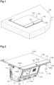
- the present invention relates, in general, to devices to be embedded in a wall, the mechanism of which is mounted on a tilting support to disappear under the wall or to be accessible by projecting from such a wall.
- the invention finds a particularly advantageous application in the production of a power outlet or a USB socket for the floor, desk or even a wall.
- the invention relates more particularly to an apparatus according to the preamble of claim 1.
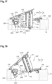
- the locking arm thus holds the equipment support in the retracted position against the thrust of the cylinder and the elastic return means acting on the locking arm itself.
- the equipment support By pressing on the equipment support, it is pushed into the opening of the frame, which causes the end of the locking arm to disengage from the gutter. This releases the locking support from its cooperation with the locking arm, which can then tilt towards its deployed position under the thrust of the cylinder.
- the locking arm also tilts towards its extended unlocking position under the action of the elastic return means.
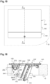
- One of the main side walls 111 of the equipment support 110 carries on its external face, near its rear edge opposite the functional front FA of the equipment 100; 100', a stop element 114 with an oblong outline, intended to engage in the stop groove 127 of the front plate 120 when the equipment support 110 tilts from its lowered position to its raised position.
- the abutment of this stop element 114 against the bottom of the stop groove 127 makes it possible to index the stable raised position of the equipment support 110 (see figure 13 ).
- This width is reduced by the width of the actuation button 140 of the locking system 300 which, here, covers the entire front longitudinal branch 121 of the frame of the front plate 120.
- the cover 130 when the equipment support 110 is in the lowered position, the cover 130 extends in the extension of the actuation key 140 placed in a waiting position, covering the entire part of the front plate 120 not covered by the actuation key 140.
- the cover 130 then has a longitudinal edge 130A which adjoins an internal longitudinal edge 140A of the actuation key 140 so that the front face 131A of the cover 130 and the front face 141A of the actuation key 140 aesthetically form a finishing front face of the equipment 100.
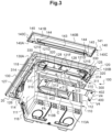
- the cover 130 is pivotally mounted on the frame of the front plate 120 about an axis X parallel to a longitudinal side of said front plate 120 (see Figure 4 ).
- the cover 130 carries on its rear face, along the longitudinal edge opposite the longitudinal edge 130A adjoining that of the control key 140, two projections, not visible in the figures, having a curved profile, engaged in two slots 129 provided along the corresponding longitudinal side of the frame of the front plate 120 (see Figure 4 ).
- the curved profile of said projections cooperates in a sliding manner with a complementary curved profile provided on the internal walls of said slots 129.
- the sliding cooperation of the projections of the cover 130 with the curved internal walls of the slots 129 of the front plate 120 allows the pivoting of the cover 130 relative to the front plate 120, around the axis X.
- the pivoting system 200; 200' comprises, inside a housing 210, here, a rotating drive shaft 220, two dampers 240 and two torsion springs 230 under stress linked to the drive shaft in rotation 220.
- the pivoting system 200; 200' further comprises two parallel connecting rods 265; 265', arranged so as to transmit the rotational movement of the rotating drive shaft 220 to said apparatus support 110.
- the pivoting system comprises a single torsion spring associated with a single shock absorber.
- the housing 210 has a generally cylindrical shape elongated along an axis Y. It has two circular openings at the ends. It is formed of two generally semi-cylindrical shells 211, positioned edge to edge and secured to each other along their longitudinal edges.
- the means for securing the two shells 211 comprise a snap-fastening system and a screwing system.
- the snap-fastening system comprises, along a longitudinal edge of one of the shells 211, two teeth 214 and, along the corresponding longitudinal edge of the other shell 211, two windows 215 into which the two teeth 214 snap.
- the screwing system comprises, along the other two corresponding longitudinal edges of the two shells 211, two threaded chimneys 212 into which two screws V1 are screwed (see Figure 12 ).
- Two cylindrical studs 251 connected to the toothed wheel 250 extend along the Y axis on either side of said toothed wheel 250.
- the toothed wheel 250 has the Y axis as its axis of rotation and the worm screw 270 extends along an axis perpendicular to the Y axis, it rotates around an axis perpendicular to the Y axis by cooperating with the teeth of the toothed wheel 250.
- Each cylindrical pad 251 is split with an axial slot 252 which opens at the free end of the pad 251.
- the toothed wheel 250 and the two cylindrical studs 251 belong to a single metal monobloc part.
- Two rotation drive systems are provided inside the housing 210, symmetrically on either side of the toothed wheel 250.
- Each rotational drive system comprises a half shaft 220, the two half shafts are aligned along the Y axis of said cylindrical studs 251 and form said Y axis rotational drive shaft 220.
- Each half shaft 220 is housed at one end of the housing 210.
- Each half shaft 220 has one end provided with a slot 221 and one end provided with a disc 222.
- the disc 222 of each half shaft 220 closes the corresponding end circular opening of the housing 210.
- Each rotary drive system comprises a damper 240 linked to the half shaft 220.
- the shock absorber 240 is completely conventional. It comprises an external cylinder 241 and an internal cylinder 244 concentric around the Y axis as well as a viscous material provided between the two cylinders.
- the external cylinder 241 carries on its external face a rib 242 extending along a generatrix of the external cylinder 241 (see Figure 4 ). This rib 242 is received in a groove 218 provided hollow in the internal face of one of the shells 211 of the housing 210 so that the external cylinder 241 of the shock absorber 240 is fixed in the housing 210.
- the internal cylinder 244 of the shock absorber 240 is capable of rotating in the external cylinder 241, rubbing on the viscous material.
- Each end of the internal cylinder 244 is equipped with an annular disc 243 which closes the internal cylindrical space provided between the external 241 and internal 244 cylinders, filled with the viscous material.
- the half shaft 220 is threaded through the internal cylinder 244 of the shock absorber 240 so that its split end 221 hooks the end 231 of a torsion spring 230.
- One of the annular discs 243 of the internal cylinder 244 of the shock absorber 240 carries studs 245 engaged in openings 224 provided correspondingly in the disc 222 provided at the end of the half shaft 220 threaded through the internal cylinder 244 of the shock absorber 240 so as to connect the half shaft 220 to said internal cylinder 244 of the shock absorber 240.
- Each rotational drive system comprises a torsion spring 230.
- One end 231 of the torsion spring 230 is connected to the split end 221 of the half shaft 220 and the other end 232 of the torsion spring 230 is engaged in the slot 252 of a cylindrical stud 251 connected to the toothed wheel 250 so as to be connected to this cylindrical stud 251 (see Figure 5 ).
- an installer simply has to screw or unscrew the worm screw 270 using a screwdriver whose tip is engaged in the slot of the operating head 272 of said worm screw 270, so as to turn the toothed wheel 250 in the appropriate direction.
- the toothed wheel 250 rotates the two studs 251 which then simultaneously cause the stress to be placed on or released from the stress of the two torsion springs 230.
- Adjusting the stress of the two torsion springs 230 makes it possible to adjust the pivoting torque of the two half-shafts 220 and therefore of the rotating drive shaft 220.
- This pivoting torque is damped by the two 240 shock absorbers.
- the closed housing 210 housing all of the elements described above, is housed in three recesses 122B provided on the rear face of the rear longitudinal branch 122 of the frame of the front plate 120, in front of said slots 129 for pivoting the cover 130.
- the housing 210 is secured to the front plate 120 by means of screws V2 engaged through two chimneys 122A provided on the rear face of the front plate 120 and opening onto the front face 120A of the rear longitudinal branch 122 of the frame of said front plate 120, these screws V2 being screwed into threaded conduits 213 provided in one of the shells 211 of the housing 210.
- the pivoting system 200; 200' very advantageously comprises a rigid one-piece transmission part 260; 260' placed outside the housing 210.
- This transmission part 260; 260' is in the form of a U with a longitudinal part 261 and two lateral parts 262.
- the longitudinal portion 261 of the transmission part 260; 260 extends, on the outside, along the housing 210, parallel to the Y axis of the rotational drive shaft 220 and said lateral portions 262 extend on either side of the ends of said housing 210 so that the transmission part 260; 260' frames the rotational drive shaft 220.
- the rotating drive shaft 220 is connected to this one-piece transmission part 260; 260', at the root of the two lateral parts 262 whose free ends form said connecting rods 265; 265' and cooperate in a sliding manner with said equipment support 110.
- each of said lateral parts 262 of the transmission part 260; 260' is a cheek 263 linked to said longitudinal part 261 and having a circular outline.
- said transmission part can be produced by molding a metallic material such as Zamak.
- the support wall 141 of the actuation key 140 is oriented lengthwise parallel to the parts of the internal 121C and external 120C peripheral edges of the front plate 120 forming the longitudinal edges of said front longitudinal branch 121 of the front plate 120.
Landscapes
- Engineering & Computer Science (AREA)
- Architecture (AREA)
- Civil Engineering (AREA)
- Structural Engineering (AREA)
- Casings For Electric Apparatus (AREA)
- Supports Or Holders For Household Use (AREA)
- Power-Operated Mechanisms For Wings (AREA)
- Pinball Game Machines (AREA)
- Patch Boards (AREA)
Claims (9)
- Gerät (100), das- eine Frontplatte (120), die einen zwischen einem äußeren umlaufenden Rand (120C) und einem inneren umlaufenden Rand (121C, 122C, 123C) begrenzten Rahmen, der eine Öffnung (124) begrenzt;- einen Geräteträger (110), der durch die Öffnung zwischen einer abgesenkten Stellung, in der er sich unter der Frontplatte erstreckt, und einer angehobenen Stellung, in der er sich zum größten Teil oberhalb der Frontplatte erstreckt, kippbar montiert ist;- ein Verriegelungssystem (300), das einerseits mindestens einen Verriegelungsarm (310) aufweist, der sich der Länge nach zwischen einem einen Blockierteil (311) bildenden Endteil und einem anderen, entgegengesetzt gerichteten Endteil erstreckt, der einen Betätigungsteil (312) bildet und der zwischen einer Verriegelungsposition, in der der Blockierteil (311) an einer Blockieroberfläche (118) des Geräteträgers (110) anliegt, und einer Freigabeposition, in der der Blockierteil (311) von der Blockieroberfläche (118) beabstandet ist, bewegbar ist, und andererseits eine vom Geräteträger (110) verschiedene Betätigungstaste (140) aufweist, die einerseits eine Druckwand (141) aufweist, die oberhalb eines Schenkels (121) des Rahmens, der zwischen einem Teil des äußeren umlaufenden Rands und des inneren umlaufenden Rands begrenzt ist und eine Vorderfront (141A) aufweist, die eine Druckfläche für einen Finger eines Benutzers bildet, angeordnet ist und andererseits mit dem Verriegelungsarm zum Steuern der Verlagerung dieses Verriegelungsarms (310) zusammenwirkt, wobei die Betätigungstaste um eine Kippachse (X1), die sich parallel zur Mittelebene (P) der Frontplatte (120) erstreckt, zwischen einer Warteposition, in der sich die Vorderfront (141A) der Druckwand (141) im Wesentlichen parallel zur Mittelebene (P) der Frontplatte (120) erstreckt, und einer nach außerhalb der Frontplatte (120) gekippten Betätigungsposition, in der die Druckwand (141) mit ihrer gegenüber der Mittelebene (P) der Frontplatte (120) geneigten Vorderfront (141A) näher zum äußeren umlaufenden Rand (120C) der Frontplatte (120) gebracht ist, kippbar ist, wobei der Verriegelungsarm (310) um eine in der Nähe seines Betätigungsteils (312) und senkrecht zur Schwenkachse (X1) der Betätigungstaste (140) gelegene Schwenkachse (Z) schwenkbar ist,wobei die Betätigungstaste (140) eine Betätigungsrippe (143) aufweist, die sich von der Rückseite der Druckwand aus in der Höhe nach hinten im Wesentlichen quer zur Druckwand erstreckt, wobei diese Betätigungsrippe in ständigem Kontakt mit dem Betätigungsteil (312) des Verriegelungsarms (310) ist, undwobei elastische, zwischen dem Verriegelungsarm (310) und der Betätigungsrippe (143) zusammengedrückte Rückstellmittel (320) vorgesehen sind, um den Verriegelungsarm (310) permanent in seine Verriegelungsstellung zu drücken und außerdem permanent auf die Betätigungstaste (140) einzuwirken, um sie in ihre Warteposition zurückzubringen.
- Gerät (100) gemäß Anspruch 1, bei dem zwei Verriegelungsarme (310) vorgesehen sind, die so positioniert sind, daß deren Betätigungsteile (312) nahe beieinander sind, in ständigem Kontakt mit der Betätigungsrippe (143) der Betätigungstaste (140), und daß deren Schwenkachsen (Z) in der Mittelebene (P) der Frontplatte (120) auf einer zu den umlaufenden inneren und äußeren Rändern der Frontplatte, die die Längsränder des Schenkels (121) der Frontplatte (120) bilden, parallelen Linie angeordnet sind.
- Gerät (100) gemäß einem der vorangehenden Ansprüche, bei dem die Druckwand der Betätigungstaste (140) eine rechteckige Kontur aufweist und sich die Betätigungsrippe der Länge nach parallel zu den Längsrändern der Druckwand (141) erstreckt.
- Gerät (100) gemäß dem vorangehenden Anspruch, bei dem die Druckwand (141) der Betätigungstaste (140) der Länge nach parallel zu den Schenkeln der umlaufenden inneren (121C) und äußeren (120C) Ränder der Frontplatte (120), die die Längsränder des Schenkels (121) der Frontplatte bilden, ausgerichtet ist.
- Gerät (100) gemäß dem vorangehenden Anspruch, bei dem die Druckwand (141) eine gestreckte Oberfläche und eine Länge aufweist, die etwas größer als die Länge des Schenkels (121) der Frontplatte (120) ist, so daß sie einen größten Teil der Vorderseite des Schenkels der Frontplatte und einen Teil des umlaufenden äußeren Rands (120C) der Frontplatte (120) bedeckt, die einerseits den ganzen äußeren Längsrand des Schenkels und andererseits einen Teil der Querränder dieses Schenkels (121) bildet.
- Gerät (100) gemäß einem der vorangehenden Ansprüche, bei dem die Druckwand der Betätigungstaste eine rechteckige Kontur aufweist und sich die Betätigungsrippe der Länge nach quer zu den Längsrändern der Druckwand erstreckt.
- Gerät (100) gemäß dem vorangehenden Anspruch, bei dem die Druckwand der Betätigungstaste der Länge nach quer zu den Teilen des inneren und des äußeren umlaufenden Rands des Schenkels der Frontplatte ausgerichtet ist.
- Gerät (100) gemäß einem der vorangehenden Ansprüche, bei dem die Frontplatte (120) einen von der Betätigungsrippe (143) der Betätigungstaste (140) durchquerten Schlitz (121A) aufweist, um den Verriegelungsarm (310) zu erreichen.
- Gerät (100) gemäß dem vorangehenden Anspruch, bei dem die Betätigungsrippe (143) der Betätigungstaste auf einer ihrer Seiten mindestens eine Verdickung (144) aufweist, die sich der Länge nach auf der Höhe der Betätigungsrippe erstreckt, wobei jede Verdickung dazu ausgelegt ist, mit einem inneren Teil der Frontplatte, der sich entlang eines Rands des Schlitzes (121A) erstreckt, in Kontakt zu kommen, um die Warteposition der Betätigungstaste (140) anzuzeigen.
Applications Claiming Priority (1)
| Application Number | Priority Date | Filing Date | Title |
|---|---|---|---|
| FR1913238A FR3103643B1 (fr) | 2019-11-26 | 2019-11-26 | Appareillage avec un support d’appareillage basculant et un système de verrouillage débrayable au moyen d’une touche d’actionnement basculante |
Publications (3)
| Publication Number | Publication Date |
|---|---|
| EP3829014A1 EP3829014A1 (de) | 2021-06-02 |
| EP3829014B1 true EP3829014B1 (de) | 2025-07-09 |
| EP3829014C0 EP3829014C0 (de) | 2025-07-09 |
Family
ID=69903332
Family Applications (1)
| Application Number | Title | Priority Date | Filing Date |
|---|---|---|---|
| EP20201667.1A Active EP3829014B1 (de) | 2019-11-26 | 2020-10-14 | Gerät mit einer kippbaren gerätehalterung und einem verriegelungssystem, das mittels eines kippbaren betätigungsknopfes entriegelt werden kann |
Country Status (6)
| Country | Link |
|---|---|
| US (1) | US12006756B2 (de) |
| EP (1) | EP3829014B1 (de) |
| CN (1) | CN112952445B (de) |
| ES (1) | ES3039864T3 (de) |
| FR (1) | FR3103643B1 (de) |
| PL (1) | PL3829014T3 (de) |
Citations (1)
| Publication number | Priority date | Publication date | Assignee | Title |
|---|---|---|---|---|
| EP2458700B1 (de) * | 2010-11-29 | 2015-02-18 | Legrand France | Elektrisches Gerät mit Stützvorrichtung für ein schwenkbares Gerät |
Family Cites Families (25)
| Publication number | Priority date | Publication date | Assignee | Title |
|---|---|---|---|---|
| DE2354858C3 (de) * | 1973-11-02 | 1979-02-22 | Karl M. Reich, Maschinenfabrik Gmbh, 7440 Nuertingen | Auflagevorrichtung an einer Plattenaufteilsäge mit aufrechtem Gestell |
| US5008491A (en) * | 1987-08-24 | 1991-04-16 | Butler Manufacturing Company | Floor box for access floors |
| US5775746A (en) * | 1994-06-21 | 1998-07-07 | Charlton; John | Retractable door stop security device/utility box |
| US6979209B2 (en) * | 2003-01-29 | 2005-12-27 | Krueger International, Inc. | Biased utility receptacle assembly |
| FR2914507B1 (fr) * | 2007-03-30 | 2009-07-03 | Legrand France | Prise de courant a couvercle mobile comportant des moyens de verrouillage/deverrouillage a loquet |
| CN201051576Y (zh) * | 2007-05-25 | 2008-04-23 | 赵谌 | 一种隐藏式翻弹插座盒 |
| WO2008154021A1 (en) * | 2007-06-11 | 2008-12-18 | Byrne Norman R | Latching power and data center |
| FR2967829B1 (fr) * | 2010-11-18 | 2012-11-02 | Legrand France | Prise electrique comportant des montants lateraux mobiles en translation |
| CN202159822U (zh) * | 2011-06-10 | 2012-03-07 | 董勇 | 安全启动地面插座 |
| CN103732985B (zh) * | 2011-07-29 | 2018-01-02 | 东芝照明技术株式会社 | 灯座、灯装置及照明器具 |
| KR101278472B1 (ko) * | 2012-11-20 | 2013-07-02 | 주식회사 리퓨터 | Usb 소켓을 구비한 컴퓨터 마우스 |
| CN204927664U (zh) * | 2015-09-12 | 2015-12-30 | 叶志荣 | 一种防水防尘安全型弹起式地面插座 |
| US20180034220A1 (en) * | 2015-11-17 | 2018-02-01 | Eric Forti | Retractable Recessed Electrical Outlet and Data Port Assembly |
| CN105576408B (zh) * | 2015-12-21 | 2017-11-28 | 公牛集团有限公司 | 具有按键选择功能的转换器 |
| CN205670595U (zh) * | 2016-06-08 | 2016-11-02 | 浙江佳龙电气有限公司 | 按键开关机构 |
| CN106602340B (zh) | 2017-01-06 | 2019-02-12 | 飞利富科技股份有限公司 | 一种面板插座 |
| CN206516829U (zh) | 2017-01-06 | 2017-09-22 | 飞利富科技股份有限公司 | 一种面板插座 |
| CN206412531U (zh) | 2017-01-06 | 2017-08-15 | 飞利富科技股份有限公司 | 一种用于面板插座的启闭结构 |
| CN206412522U (zh) | 2017-01-06 | 2017-08-15 | 飞利富科技股份有限公司 | 一种插座的阻尼结构 |
| CN106785639B (zh) | 2017-01-06 | 2023-12-15 | 飞利富科技股份有限公司 | 一种用于面板插座的启闭结构 |
| TWI651899B (zh) * | 2017-06-14 | 2019-02-21 | 黃沛霖 | 插座結構 |
| FR3074368B1 (fr) * | 2017-11-29 | 2021-08-06 | Soc Financiere Veron Sofive | Boitier electrique deployable avec moyens de verrouillage de la partie mobile en position escamotee |
| DE102018101670B3 (de) * | 2018-01-25 | 2019-04-04 | Lumberg Connect Gmbh | Steckverbinder mit primärverriegelnden Rastarmen |
| TWM569097U (zh) * | 2018-07-31 | 2018-10-21 | 台芝電氣股份有限公司 | Lifting floor socket |
| CN209266770U (zh) * | 2019-01-11 | 2019-08-16 | 宁波维能进出口有限公司 | 一种隐藏式电源板 |
-
2019
- 2019-11-26 FR FR1913238A patent/FR3103643B1/fr active Active
-
2020
- 2020-10-14 EP EP20201667.1A patent/EP3829014B1/de active Active
- 2020-10-14 PL PL20201667.1T patent/PL3829014T3/pl unknown
- 2020-10-14 ES ES20201667T patent/ES3039864T3/es active Active
- 2020-11-24 US US17/103,525 patent/US12006756B2/en active Active
- 2020-11-25 CN CN202011343602.9A patent/CN112952445B/zh active Active
Patent Citations (1)
| Publication number | Priority date | Publication date | Assignee | Title |
|---|---|---|---|---|
| EP2458700B1 (de) * | 2010-11-29 | 2015-02-18 | Legrand France | Elektrisches Gerät mit Stützvorrichtung für ein schwenkbares Gerät |
Also Published As
| Publication number | Publication date |
|---|---|
| PL3829014T3 (pl) | 2025-12-01 |
| ES3039864T3 (en) | 2025-10-27 |
| EP3829014A1 (de) | 2021-06-02 |
| FR3103643B1 (fr) | 2022-06-10 |
| US12006756B2 (en) | 2024-06-11 |
| CN112952445A (zh) | 2021-06-11 |
| US20210156185A1 (en) | 2021-05-27 |
| CN112952445B (zh) | 2023-04-25 |
| FR3103643A1 (fr) | 2021-05-28 |
| EP3829014C0 (de) | 2025-07-09 |
Similar Documents
| Publication | Publication Date | Title |
|---|---|---|
| EP0705727B1 (de) | Gelenkebeschlag für eine Fahrzeugsitzrückenlehne | |
| FR2822419A1 (fr) | Siege de vehicule equipe d'un mecanisme d'articulation | |
| FR2766139A1 (fr) | Dispositif d'articulation pour siege de vehicule, et siege de vehicule comportant un tel dispositif | |
| FR2934802A1 (fr) | Pistolet a attaches | |
| EP4026463B1 (de) | Abnehmbarer griff mit optimiertem zusammenbauverfahren | |
| EP2248717A1 (de) | Fahrradsattelrohr mit regulierbarer Länge | |
| EP3829015B1 (de) | Gerät mit halterung für schwenkbares gerät | |
| EP1026347B1 (de) | Türgriff für Kraftfahrzeuge mit verbesserten Mitteln zur Montage des Griffelements | |
| EP3829014B1 (de) | Gerät mit einer kippbaren gerätehalterung und einem verriegelungssystem, das mittels eines kippbaren betätigungsknopfes entriegelt werden kann | |
| EP3253615B1 (de) | Entkuppelbare gelenkanordnung für einen kraftfahrzeugsitz | |
| EP2163466A1 (de) | Intergriertes Scharnier für Klappfahrrad | |
| EP0951411B1 (de) | Scheibenwischer für ein kraftfahrzeug mit einer feder zur erzeugung eines wischdruckes | |
| FR2713064A1 (fr) | Siège dont le dossier articulé fait office de couverture de protection pour l'assise lorsqu'il est rabattu. | |
| CH675053A5 (de) | ||
| EP4053369B1 (de) | Schwenksystem für einen geräteträger und einbaugerät mit einem solchen schwenksystem | |
| EP2745887B1 (de) | Fixierung für Schuhwerk auf einem Sportgerät | |
| FR2907080A1 (fr) | Dispositif de fixation d'un bras d'essuie-glace de vehicule automobile | |
| WO2015011385A1 (fr) | Cycle pliable | |
| EP1770234B1 (de) | Treibstangenverschluss oder dergleichen | |
| FR2536666A1 (fr) | Fixation de securite pour ski | |
| FR2909048A1 (fr) | Dispositif de commande a double sens pour mecanisme d'articulation comprenant un tel dispositif et siege comprenant un tel ensemble d'articulation. | |
| FR2766858A1 (fr) | Dispositif de rappel a ressort pour poignees de portes ou de fenetres | |
| FR2912357A1 (fr) | Siege d'automobile comportant un carter de recouvrement d'un element d'armature articule. | |
| FR2825406A1 (fr) | Dispositif de montage a articulation d'un ouvrant sur un dormant et armoire electrique a deux sens d'ouverture comportant un tel dispositif | |
| EP1895078A1 (de) | Einklappbare Schlüsselvorrichtung und Montageverfahren |
Legal Events
| Date | Code | Title | Description |
|---|---|---|---|
| PUAI | Public reference made under article 153(3) epc to a published international application that has entered the european phase |
Free format text: ORIGINAL CODE: 0009012 |
|
| STAA | Information on the status of an ep patent application or granted ep patent |
Free format text: STATUS: THE APPLICATION HAS BEEN PUBLISHED |
|
| AK | Designated contracting states |
Kind code of ref document: A1 Designated state(s): AL AT BE BG CH CY CZ DE DK EE ES FI FR GB GR HR HU IE IS IT LI LT LU LV MC MK MT NL NO PL PT RO RS SE SI SK SM TR |
|
| STAA | Information on the status of an ep patent application or granted ep patent |
Free format text: STATUS: REQUEST FOR EXAMINATION WAS MADE |
|
| 17P | Request for examination filed |
Effective date: 20210806 |
|
| RBV | Designated contracting states (corrected) |
Designated state(s): AL AT BE BG CH CY CZ DE DK EE ES FI FR GB GR HR HU IE IS IT LI LT LU LV MC MK MT NL NO PL PT RO RS SE SI SK SM TR |
|
| STAA | Information on the status of an ep patent application or granted ep patent |
Free format text: STATUS: EXAMINATION IS IN PROGRESS |
|
| 17Q | First examination report despatched |
Effective date: 20230322 |
|
| GRAP | Despatch of communication of intention to grant a patent |
Free format text: ORIGINAL CODE: EPIDOSNIGR1 |
|
| STAA | Information on the status of an ep patent application or granted ep patent |
Free format text: STATUS: GRANT OF PATENT IS INTENDED |
|
| INTG | Intention to grant announced |
Effective date: 20250211 |
|
| RIC1 | Information provided on ipc code assigned before grant |
Ipc: A47B 21/06 20060101ALN20250131BHEP Ipc: H02G 3/18 20060101ALI20250131BHEP Ipc: H02G 3/14 20060101AFI20250131BHEP |
|
| GRAS | Grant fee paid |
Free format text: ORIGINAL CODE: EPIDOSNIGR3 |
|
| GRAA | (expected) grant |
Free format text: ORIGINAL CODE: 0009210 |
|
| STAA | Information on the status of an ep patent application or granted ep patent |
Free format text: STATUS: THE PATENT HAS BEEN GRANTED |
|
| AK | Designated contracting states |
Kind code of ref document: B1 Designated state(s): AL AT BE BG CH CY CZ DE DK EE ES FI FR GB GR HR HU IE IS IT LI LT LU LV MC MK MT NL NO PL PT RO RS SE SI SK SM TR |
|
| REG | Reference to a national code |
Ref country code: GB Ref legal event code: FG4D Free format text: NOT ENGLISH |
|
| REG | Reference to a national code |
Ref country code: CH Ref legal event code: EP |
|
| REG | Reference to a national code |
Ref country code: IE Ref legal event code: FG4D Free format text: LANGUAGE OF EP DOCUMENT: FRENCH |
|
| U01 | Request for unitary effect filed |
Effective date: 20250715 |
|
| U07 | Unitary effect registered |
Designated state(s): AT BE BG DE DK EE FI FR IT LT LU LV MT NL PT RO SE SI Effective date: 20250721 |
|
| U20 | Renewal fee for the european patent with unitary effect paid |
Year of fee payment: 6 Effective date: 20250829 |
|
| PGFP | Annual fee paid to national office [announced via postgrant information from national office to epo] |
Ref country code: TR Payment date: 20250826 Year of fee payment: 6 |
|
| REG | Reference to a national code |
Ref country code: SK Ref legal event code: T3 Ref document number: E 46958 Country of ref document: SK |
|
| PGFP | Annual fee paid to national office [announced via postgrant information from national office to epo] |
Ref country code: GB Payment date: 20250805 Year of fee payment: 6 |
|
| PGFP | Annual fee paid to national office [announced via postgrant information from national office to epo] |
Ref country code: CZ Payment date: 20250718 Year of fee payment: 6 |
|
| PGFP | Annual fee paid to national office [announced via postgrant information from national office to epo] |
Ref country code: SK Payment date: 20250718 Year of fee payment: 6 |
|
| REG | Reference to a national code |
Ref country code: ES Ref legal event code: FG2A Ref document number: 3039864 Country of ref document: ES Kind code of ref document: T3 Effective date: 20251027 |
|
| REG | Reference to a national code |
Ref country code: CH Ref legal event code: U11 Free format text: ST27 STATUS EVENT CODE: U-0-0-U10-U11 (AS PROVIDED BY THE NATIONAL OFFICE) Effective date: 20251101 |
|
| PG25 | Lapsed in a contracting state [announced via postgrant information from national office to epo] |
Ref country code: IS Free format text: LAPSE BECAUSE OF FAILURE TO SUBMIT A TRANSLATION OF THE DESCRIPTION OR TO PAY THE FEE WITHIN THE PRESCRIBED TIME-LIMIT Effective date: 20251109 |
|
| PG25 | Lapsed in a contracting state [announced via postgrant information from national office to epo] |
Ref country code: NO Free format text: LAPSE BECAUSE OF FAILURE TO SUBMIT A TRANSLATION OF THE DESCRIPTION OR TO PAY THE FEE WITHIN THE PRESCRIBED TIME-LIMIT Effective date: 20251009 |
|
| PG25 | Lapsed in a contracting state [announced via postgrant information from national office to epo] |
Ref country code: HR Free format text: LAPSE BECAUSE OF FAILURE TO SUBMIT A TRANSLATION OF THE DESCRIPTION OR TO PAY THE FEE WITHIN THE PRESCRIBED TIME-LIMIT Effective date: 20250709 |
|
| PG25 | Lapsed in a contracting state [announced via postgrant information from national office to epo] |
Ref country code: GR Free format text: LAPSE BECAUSE OF FAILURE TO SUBMIT A TRANSLATION OF THE DESCRIPTION OR TO PAY THE FEE WITHIN THE PRESCRIBED TIME-LIMIT Effective date: 20251010 |
|
| PGFP | Annual fee paid to national office [announced via postgrant information from national office to epo] |
Ref country code: CH Payment date: 20251101 Year of fee payment: 6 |
|
| PGFP | Annual fee paid to national office [announced via postgrant information from national office to epo] |
Ref country code: PL Payment date: 20250721 Year of fee payment: 6 |
|
| PG25 | Lapsed in a contracting state [announced via postgrant information from national office to epo] |
Ref country code: RS Free format text: LAPSE BECAUSE OF FAILURE TO SUBMIT A TRANSLATION OF THE DESCRIPTION OR TO PAY THE FEE WITHIN THE PRESCRIBED TIME-LIMIT Effective date: 20251009 |
|
| PGFP | Annual fee paid to national office [announced via postgrant information from national office to epo] |
Ref country code: ES Payment date: 20251103 Year of fee payment: 6 |