EP3828991A1 - Battery pack - Google Patents
Battery pack Download PDFInfo
- Publication number
- EP3828991A1 EP3828991A1 EP20210423.8A EP20210423A EP3828991A1 EP 3828991 A1 EP3828991 A1 EP 3828991A1 EP 20210423 A EP20210423 A EP 20210423A EP 3828991 A1 EP3828991 A1 EP 3828991A1
- Authority
- EP
- European Patent Office
- Prior art keywords
- battery cells
- battery
- battery cell
- end portion
- cell
- Prior art date
- Legal status (The legal status is an assumption and is not a legal conclusion. Google has not performed a legal analysis and makes no representation as to the accuracy of the status listed.)
- Pending
Links
Images








Classifications
-
- H—ELECTRICITY
- H01—ELECTRIC ELEMENTS
- H01M—PROCESSES OR MEANS, e.g. BATTERIES, FOR THE DIRECT CONVERSION OF CHEMICAL ENERGY INTO ELECTRICAL ENERGY
- H01M50/00—Constructional details or processes of manufacture of the non-active parts of electrochemical cells other than fuel cells, e.g. hybrid cells
- H01M50/20—Mountings; Secondary casings or frames; Racks, modules or packs; Suspension devices; Shock absorbers; Transport or carrying devices; Holders
-
- H—ELECTRICITY
- H01—ELECTRIC ELEMENTS
- H01M—PROCESSES OR MEANS, e.g. BATTERIES, FOR THE DIRECT CONVERSION OF CHEMICAL ENERGY INTO ELECTRICAL ENERGY
- H01M50/00—Constructional details or processes of manufacture of the non-active parts of electrochemical cells other than fuel cells, e.g. hybrid cells
- H01M50/50—Current conducting connections for cells or batteries
- H01M50/502—Interconnectors for connecting terminals of adjacent batteries; Interconnectors for connecting cells outside a battery casing
- H01M50/503—Interconnectors for connecting terminals of adjacent batteries; Interconnectors for connecting cells outside a battery casing characterised by the shape of the interconnectors
-
- H—ELECTRICITY
- H01—ELECTRIC ELEMENTS
- H01M—PROCESSES OR MEANS, e.g. BATTERIES, FOR THE DIRECT CONVERSION OF CHEMICAL ENERGY INTO ELECTRICAL ENERGY
- H01M10/00—Secondary cells; Manufacture thereof
- H01M10/42—Methods or arrangements for servicing or maintenance of secondary cells or secondary half-cells
- H01M10/4207—Methods or arrangements for servicing or maintenance of secondary cells or secondary half-cells for several batteries or cells simultaneously or sequentially
-
- H—ELECTRICITY
- H01—ELECTRIC ELEMENTS
- H01M—PROCESSES OR MEANS, e.g. BATTERIES, FOR THE DIRECT CONVERSION OF CHEMICAL ENERGY INTO ELECTRICAL ENERGY
- H01M50/00—Constructional details or processes of manufacture of the non-active parts of electrochemical cells other than fuel cells, e.g. hybrid cells
- H01M50/20—Mountings; Secondary casings or frames; Racks, modules or packs; Suspension devices; Shock absorbers; Transport or carrying devices; Holders
- H01M50/204—Racks, modules or packs for multiple batteries or multiple cells
-
- H—ELECTRICITY
- H01—ELECTRIC ELEMENTS
- H01M—PROCESSES OR MEANS, e.g. BATTERIES, FOR THE DIRECT CONVERSION OF CHEMICAL ENERGY INTO ELECTRICAL ENERGY
- H01M50/00—Constructional details or processes of manufacture of the non-active parts of electrochemical cells other than fuel cells, e.g. hybrid cells
- H01M50/20—Mountings; Secondary casings or frames; Racks, modules or packs; Suspension devices; Shock absorbers; Transport or carrying devices; Holders
- H01M50/204—Racks, modules or packs for multiple batteries or multiple cells
- H01M50/207—Racks, modules or packs for multiple batteries or multiple cells characterised by their shape
- H01M50/213—Racks, modules or packs for multiple batteries or multiple cells characterised by their shape adapted for cells having curved cross-section, e.g. round or elliptic
-
- H—ELECTRICITY
- H01—ELECTRIC ELEMENTS
- H01M—PROCESSES OR MEANS, e.g. BATTERIES, FOR THE DIRECT CONVERSION OF CHEMICAL ENERGY INTO ELECTRICAL ENERGY
- H01M50/00—Constructional details or processes of manufacture of the non-active parts of electrochemical cells other than fuel cells, e.g. hybrid cells
- H01M50/50—Current conducting connections for cells or batteries
- H01M50/502—Interconnectors for connecting terminals of adjacent batteries; Interconnectors for connecting cells outside a battery casing
-
- H—ELECTRICITY
- H01—ELECTRIC ELEMENTS
- H01M—PROCESSES OR MEANS, e.g. BATTERIES, FOR THE DIRECT CONVERSION OF CHEMICAL ENERGY INTO ELECTRICAL ENERGY
- H01M50/00—Constructional details or processes of manufacture of the non-active parts of electrochemical cells other than fuel cells, e.g. hybrid cells
- H01M50/50—Current conducting connections for cells or batteries
- H01M50/572—Means for preventing undesired use or discharge
-
- H—ELECTRICITY
- H01—ELECTRIC ELEMENTS
- H01M—PROCESSES OR MEANS, e.g. BATTERIES, FOR THE DIRECT CONVERSION OF CHEMICAL ENERGY INTO ELECTRICAL ENERGY
- H01M2200/00—Safety devices for primary or secondary batteries
- H01M2200/10—Temperature sensitive devices
- H01M2200/103—Fuse
-
- H—ELECTRICITY
- H01—ELECTRIC ELEMENTS
- H01M—PROCESSES OR MEANS, e.g. BATTERIES, FOR THE DIRECT CONVERSION OF CHEMICAL ENERGY INTO ELECTRICAL ENERGY
- H01M2220/00—Batteries for particular applications
- H01M2220/20—Batteries in motive systems, e.g. vehicle, ship, plane
-
- Y—GENERAL TAGGING OF NEW TECHNOLOGICAL DEVELOPMENTS; GENERAL TAGGING OF CROSS-SECTIONAL TECHNOLOGIES SPANNING OVER SEVERAL SECTIONS OF THE IPC; TECHNICAL SUBJECTS COVERED BY FORMER USPC CROSS-REFERENCE ART COLLECTIONS [XRACs] AND DIGESTS
- Y02—TECHNOLOGIES OR APPLICATIONS FOR MITIGATION OR ADAPTATION AGAINST CLIMATE CHANGE
- Y02E—REDUCTION OF GREENHOUSE GAS [GHG] EMISSIONS, RELATED TO ENERGY GENERATION, TRANSMISSION OR DISTRIBUTION
- Y02E60/00—Enabling technologies; Technologies with a potential or indirect contribution to GHG emissions mitigation
- Y02E60/10—Energy storage using batteries
Definitions
- Embodiments relate to a battery pack.
- a secondary battery may be charged and discharged, unlike a primary battery that may not be recharged.
- a secondary battery may be used as an energy source for mobile devices, electric vehicles, hybrid vehicles, electric bicycles, uninterruptible power supplies, and so on, and is used in the form of a single battery cell depending on types of external devices to be applied, or is used in the form of a battery pack in which multiple battery cells are connected to each other to be composed of one unit.
- Small mobile devices such as mobile phones may operate for a predetermined period of time with an output and capacity of a single battery, but when electric vehicles and hybrid vehicles that consume much power require long-time driving and high-power driving, a battery pack may be used due to an output and a capacity, and the battery pack may increase an output voltage or an output current according to the number of built-in battery cells.
- the embodiments may be realized by providing a battery pack including battery cells bounded by an imaginary rectangular envelope including a pair of long sides and a pair of short sides extending to linearly surround an outer periphery of the battery cells across an outer circumference of the battery cells; and bus bars that electrically connect at least some of the battery cells to each other, the bus bars being arranged to extend in a zig-zag shape along a short side direction of the imaginary rectangular envelope.
- Each of the battery cells may be a circular battery cell, and the battery cells may be arranged in an offset manner such that one battery cell is partially between adjacent battery cells.
- the battery cells may be arranged such that a straight line of battery cells extend along a long side direction of the imaginary rectangular envelope; and a zig-zag line of battery cells extend along the short side direction of the imaginary rectangular envelope.
- the bus bars may be arranged in the zig-zag shape while connecting adjacent battery cells along the short side direction of the imaginary rectangular envelope.
- the bus bars may be arranged such that some of the bus bars are arranged in the zig-zag shape along the short side direction of the imaginary rectangular envelope; and remaining ones of the bus bars are arranged to extend lengthwise in the long side direction of the imaginary rectangular envelope.
- a number of bus bars arranged in the zig-zag shape along the short side direction of the imaginary rectangular envelope may be greater than a number of bus bars arranged to extend lengthwise in the long side direction of the imaginary rectangular envelope.
- the battery cells may include a low-potential battery cell having a lowest potential and a high-potential battery cell having a highest potential, and first and second output terminals may be respectively connected to the low-potential battery cell and the high-potential battery cell.
- the first and second output terminals may be arranged along a long side direction of the imaginary rectangular envelope.
- the battery pack may further include first and second fuse terminals respectively connected to a pair of adjacent battery cells between the low-potential battery cell and the high-potential battery cell in an electrical connection direction in which the bus bars are arranged.
- the bus bars may include a low voltage portion extending from the first output terminal to the first fuse terminal; and a high voltage portion extending from the second output terminal to the second fuse terminal.
- the first and second fuse terminals may be respectively close to the first and second output terminals in the electrical connection direction in which the bus bars are arranged.
- the low voltage portion and the high voltage portion may be formed asymmetrically with respect to a virtual line that crosses between the first and second fuse terminals and is parallel to the short side direction of the imaginary rectangular envelope.
- a number of bus bars in the high voltage portion may be larger than a number of bus bars in the low voltage portion.
- the high voltage portion may include a high voltage deflection portion that crosses the virtual line toward the low voltage portion in the long side direction of the imaginary rectangular envelope.
- the low voltage portion may include a low voltage deflection portion close to a side opposite to the high voltage deflection portion in the short side direction of the imaginary rectangular envelope and spaced apart from the high voltage deflection portion.
- the low voltage deflection portion may be arranged at a position proximate to the first and second fuse terminals in the short side direction of the imaginary rectangular envelope, and the high voltage deflection portion may be arranged at a position distal to the first and second fuse terminals in the short side direction of the imaginary rectangular envelope.
- the high voltage deflection portion may extend longer in the long side direction of the imaginary rectangular envelope than in the short side direction of the imaginary rectangular envelope, and the low voltage deflection portion may extend relatively longer in the short side direction of the imaginary rectangular envelope than in the long side direction of the imaginary rectangular envelope.
- the bus bars may be alternately arranged over and below the battery cells in a height direction of the battery cells.
- the battery pack may further include a cell holder in which the battery cells are accommodated, wherein the bus bars are alternately arranged over and below the cell holder in the height direction of the battery cells.
- the battery pack may include arrays of the bus bars arranged to extend in the zig-zag shape along the short side direction of the imaginary rectangular envelope, the arrays being repeatedly arranged along a long side direction of the imaginary rectangular envelope.
- the terms “or” and “and/or” include any and all combinations of one or more of the associated listed items. Expressions such as “at least one of,” when preceding a list of elements, modify the entire list of elements and do not modify the individual elements of the list.
- FIG. 1 is an exploded perspective view of a battery pack according to an embodiment
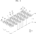
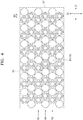
- FIGS. 2 and 3 illustrate perspective views of battery cells of FIG. 1
- FIG. 4 is a view of the battery cell of FIG. 3 and showing cooling flow paths
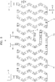
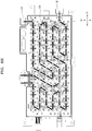
- FIG. 5 is a view of an arrangement of multiple bus bars or an electrical connection of battery cells in which multiple bus bars are arranged
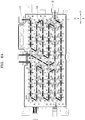
- FIGS. 6A to 6C are views schematically showing electrical connections according to a comparative example
- FIG. 7 is an exploded perspective view of a structure of a cell holder in which battery cells are assembled
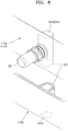
- FIG. 8 is an exploded perspective view of an exhaust hole and an exhaust pipe illustrated in FIG. 7
- FIG. 9 is a view of assembly of a bus bar and a cell holder
- FIG. 9 is a view of assembly of a bus bar and a cell holder
- FIG. 10 is a view of a structure of a circuit board of FIG. 1 ;
- FIG. 11 is a view of a potting resin and an adhesive resin respectively formed in a filling hole and a coupling opening region of FIG. 10 ;
- FIG. 12 is a cross-sectional view taken along line XII-XII of FIG. 10 ;
- FIG. 13 is a view of first and second opening regions of FIG. 10 ;
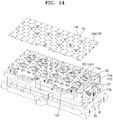
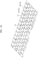
- FIGS. 14 and 15 illustrate a separation member of FIG. 1 showing opposite surfaces of upper and lower separation members, respectively;
- FIG. 16 is a view of a spatial separation of a cooling medium and an exhaust path of a cooling flow path, which is made by the separation member;
- FIG. 17 is a perspective view of an upper duct and a lower duct.
- a battery pack may include battery cells 10 of one group (e.g., a first group of battery cells 10) surrounded or bounded by an imaginary rectangular envelope S1 and S2 including a pair of long sides S1 and a pair of short sides S2 extending to linearly surround an outer periphery of the battery cells 10 of one group across an outer circumference of the battery cells 10 of one group forming the battery pack.
- a first group of battery cells e.g., a first group of battery cells
- an imaginary rectangular envelope S1 and S2 including a pair of long sides S1 and a pair of short sides S2 extending to linearly surround an outer periphery of the battery cells 10 of one group across an outer circumference of the battery cells 10 of one group forming the battery pack.
- Bus bars 120 of one group (e.g., a first group of bus bars 120) that electrically connect the battery cells 10 of one group to each other and may be arranged to electrically connect at least some of the battery cells 10 of one group and may be arranged in a transverse direction (e.g., approximately a short side direction Z2 that is different from a long side direction Z1 of the envelope S1 and S2), e.g., the bus bars may extend in a zig-zag shape.
- a transverse direction e.g., approximately a short side direction Z2 that is different from a long side direction Z1 of the envelope S1 and S2
- the batteries have a cylindrical body, such that they have a circular cross-section.
- additional structures such as connectors and electrodes may be attached on one or both ends of the cylinder.
- the batteries are arranged such that the respective axes of the cylindrical bodies are parallel to each other.
- the batteries may thus be described as "circular”, meaning that they have a circular cross section. When reference is made therefore to a circular battery in this specification, this refers to a battery with a circular cross section. When reference is made to a "height direction”, this means a direction parallel to the axis of the battery cell.
- the terms “upper” and “lower” refer to the configuration with the battery in normal operation.
- a battery pack wherein the battery cells are arranged in a plurality of rows R1, R2, R3, the rows extending in a first direction, Z1.
- the plurality of rows Z1 comprises a plurality of first rows R1, R3 and a plurality of second rows, R2, wherein the first rows alternate with the second rows.
- the respective battery cells of the plurality of first rows are aligned in a second direction, Z2, perpendicular to the first direction, and respective battery cells of the plurality of second rows are aligned in the second direction, offset from respective battery cells in the first rows.
- the number of battery cells in a row is greater than the number of rows.
- Bus bars electrically connect at least some of the battery cells to each other the bus bars being arranged to extend in a zig-zag shape in the second direction.
- a battery pack comprising: a plurality of battery cells, 10, arranged to be locatable in a cell holder, 110, the cell holder providing rectangular bound with a pair of long sides and a pair of short sides extending to linearly surround an outer periphery of the battery cells across an outer circumference of the battery cells, and bus bars that electrically connect at least some of the battery cells to each other, the bus bars being arranged to extend in a zig-zag shape along a short side direction of the cell holder.
- the battery cells 10 may each include an upper end portion 10a and a lower end portion 10b in a height direction and may be a circular battery cell 10 having an outer circumferential surface 10c of a cylindrical shape between the upper end portion 10a and the lower end portion 10b.
- First and second electrodes 11 and 12 having different polarities may be respectively on the upper end portion 10a and the lower end portion 10b of the battery cell 10.
- the first and second electrodes 11 and 12 of the battery cell 10 may respectively correspond to a first polarity (e.g., cathode) and a second polarity (e.g., anode) of the battery cell 10 which are opposite to each other.
- one of the upper end portion 10a and the lower end portion 10b of the battery cell 1 0, e.g., the lower end portion 10b, may form the first electrode 11 as a whole, and the other, e.g., the upper end portion 10a, may have a central portion that is the second electrode 12 and a rim portion that is the first electrode 11.
- the battery cell 10 illustrated in FIG. 1 in the battery cell 10 illustrated in FIG.
- the whole lower end portion 10b and the rim portion of the upper end portion 10a may be covered with a can N integrally extending so that the whole lower end portion 10b and the rim portion of the upper end portion 10a form the first electrode 11 to have the same polarity, and the central portion of the upper end portion 10a corresponding to a cap assembly E electrically insulated from the can N forming the first electrode 11 may form the second electrode 12 having a different polarity from the first electrode 11.
- a circuit board 130 extending across the multiple battery cells 10 may have a coupling hole CH (see FIG. 1 ) exposing rim portions of the upper end portions 10a of a pair of adjacent battery cells 10 therein, and the rim portions of the upper end portions 10a of the battery cells 10 exposed through the coupling hole CH may form the first electrodes 11 of the same polarity.
- the adjacent battery cells 10 exposed through the same coupling hole CH may be arranged in a vertically inverted pattern in a height direction of the battery cells 10, and the rim portions of the upper end portions 10a of the battery cells 10 may form the first electrodes 11 of the same polarity, regardless of the vertical arrangement of the battery cells 10. As can be seen in FIG.
- the can N forming the first electrode 11 may extend from the rim portion of the upper end portion 10a to the lower end portion 10b as a whole, and thereby, all of the rim portion of the upper end portion 10a of the battery cell 10 and the rim portion of the lower end portion 10b of the battery cell 10 have the first electrodes 11 of the same polarity regardless of a vertical arrangement of the battery cell 10.
- upper end portions 10a of the adjacent battery cells 10 may be electrically connected to each other by a bus bar 120, and lower end portions 10b of the adjacent battery cells 10 may be electrically connected to each other by another bus bar 120.
- the bus bar 120 may connect the central portions of the upper end portions 10a of the adjacent battery cells 10, and the bus bar 120 may connect the central portions of the lower end portions 10b of the adjacent battery cells 10.
- the central portion of the upper end portion 10a may be the cap assembly E forming the second electrode 12, and the central portion of the lower end portion 10b may be formed as the can N forming the first electrode 11, and the central portion of the upper end portion 10a of the battery cell 10 or the central portion of the lower end portion 10b of the battery cell 10 may form the first electrode 11 or the second electrode 12.
- that the upper end portion 10a and the lower end portion 10b of the battery cell 10 respectively have the first electrode 11 and the second electrode 12 or respectively form the second electrode 12 and the first electrode 11 may indicate that the central portions of the upper end portion 10a and the lower end portion 10b of the battery cell 10 respectively have the first electrode 11 and the second electrode 12 or respectively have the second electrode 12 and the first electrode 11.
- connecting the upper end portions 10a to the lower end portions 10b of the adjacent battery cells 10 through that the bus bars 120 may indicate connecting the central portions of the upper end portions 10a to each other through the bus bars 120 and connecting the central portions of the lower end portions 10b to each other through the bus bars 120.
- the upper end portion 10a and the lower end portion 10b of the battery cell 10 may be divided according to positions rather than the first and second electrodes 11 and 12 and may respectively indicate an end portion formed at an upper position and an end portion formed at a lower position in a height direction.
- the upper end portions 10a of the adjacent battery cells 10 may form the first electrode 11 or the second electrode 12 having the same polarity or may also form the first and second electrodes 11 and 12 having different polarities depending on the specific arrangement of the battery cells 10.
- the adjacent battery cells 10 may be arranged in an inverted pattern in a height direction, and accordingly, the upper end portions 10a of the adjacent battery cells 10 may form the first and second electrodes 11 and 12 having different polarities, and the lower end portions 10b of the adjacent battery cells 10 may also form the first and second electrodes 11 and 12 having different polarities.
- the battery cells 10 may be electrically connected to other adjacent battery cells 10, and the first and second electrodes 11 and 12 of the battery cells 10 may be connected in series to electrodes having different polarities while the battery cells 10 adjacent in an electrical connection direction are arranged in an inverted pattern in a height direction.
- each of a group of the battery cells 10 forming a battery pack may be connected in series with the adjacent battery cell 10, and a battery pack according to an embodiment may not include a parallel connection between the adjacent battery cells 10.
- the adjacent battery cells 10 in an electrical connection direction may be arranged in a vertically inverted pattern, and a series connection between the first and second electrodes 11 and 12 having different polarities may be formed by connecting the upper end portions 10a to each other or connecting the lower end portions 10b to each other.
- the battery cells 10 may alternate in an up or down direction, e.g., in which the first electrode 11 of one battery cell 10 faces upwardly and the first electrode of the next battery cell 10 faces downwardly.
- the electrical connection direction of the battery cells 10 indicates a direction in which the adjacent battery cells 10 are electrically connected to each other and may include different directions interconnected through an arrangement of multiple bus bars 120 rather than indicating a certain one direction (e.g., would not indicate a simple linear direction).
- the electrical connection direction of the battery cell 10 may be formed in a zig-zag shape.
- the battery cell 10 may a circular battery cell, and multiple battery cells 10 may be densely arranged by arranging the battery cells 10 at alternate positions so as to be between adjacent battery cells 10 (e.g., the battery cells 10 may be in an offset arrangement such that the battery cells may be tightly packed.
- the battery cells may be arranged in a staggered manner, such that each battery cells is at least partially between adjacent battery cells).
- the multiple battery cells 10 arranged at alternate positions may be electrically connected to each other by the multiple bus bars 120 arranged in a zig-zag shape, and the electrical connection direction of the zig-zag shape may be formed in a direction in which the multiple bus bars 120 are arranged.
- a group of the battery cells 10 forming a battery pack may be electrically connected to each other in the electrical connection direction in which the multiple bus bars 120 are arranged, and the battery cell 10 forming one end in the electrical connection direction and the battery cell 10 forming the other end may respectively correspond to a low-potential battery cell 10 (having the lowest potential) and a high-potential battery cell 10 (having the highest potential) among a group of battery cells 10.
- first and second output terminals 121 and 122 may be respectively connected to the low-potential battery cell 10 and the high-potential battery cell 10.
- the first and second output terminals 121 and 122 may mediate an electrical connection between a group of the battery cells 10 electrically connected to each other and an external device, and a group of the battery cells 10 may supply a discharge power to an external load through the first and second output terminals 121 and 122 or may receive a charging power from an external charger through the first and second output terminals 121 and 122.
- First and second fuse terminals 123 and 124 may be between the first and second output terminals 121 and 122 to be connected to a fuse box forming a charge/discharge path by being between the first and second output terminals 121 and 122.
- the fuse box may form a charge/discharge path between the first and second output terminals 121 and 122, and the charge/discharge path of a group of the battery cells 10 may pass through a fuse box (through the first and second fuse terminals 123 and 124 connected to the fuse box.
- a fuse for blocking an overcurrent may be installed in the fuse box and may block the charge/discharge path in response to the overcurrent.
- the first and second fuse terminals 123 and 124 may be connected to the battery cell 10 between the low-potential battery cell 10 at one end and the high-potential battery cell 10 at the other end in an electrical connection direction of the battery cells 10 in which the multiple bus bars 120 are arranged, and may be formed in pairs to be respectively connected to a pair of the battery cells 10 electrically connected to each other through a fuse box connected to the first and second fuse terminals 123 and 124.
- the first and second fuse terminals 123 and 124 may respectively correspond to fuse terminals close to the first and second output terminals 121 and 122 in an electrical connection direction of the battery cells 10 in which multiple bus bars 120 are arranged.
- Cooling flow paths F may be between the adjacent battery cells 10.
- a cooling medium flowing through the cooling flow paths F may be in contact with the battery cells 10 to cool the battery cells 10.
- the cooling flow path F may penetrate a space between the adjacent battery cells 10 in a height direction of the battery cell 10 and extend to the outside of the battery cell 10, and the cooling flow path F formed to penetrate almost the whole battery pack may be in fluid communication with the outside of the battery pack through an inlet and an outlet of the cooling flow path F. In this case, the cooling flow path F may extend across the battery pack to penetrate almost the whole battery pack in the height direction of the battery cell 10.
- the cooling flow path F will be described below in greater detail.
- a vent portion 13 may be formed at at least one end portion of the upper end portion 10a and the lower end portion 10b of the battery cell 10.
- the vent portion 13 may be formed along a rim of the one end portion of the battery cell 10.
- the vent portion 13 may be formed along a rim of the second electrode 12 formed at a central position of the one end portion of the battery cell 10, and may be formed along a rim of the one end portion of the battery cell 10.
- the vent portion 13 may include multiple vent portions 13 spaced apart from each other along a rim in one end portion of the battery cell 10.
- the vent portion 13 may be for relieving an internal pressure of the battery cell 1 0, e.g., the vent portion 13 may correspond to a portion formed with a relatively weak strength in one end portion of the battery cell 10.
- the vent portion 13 may be broken to relieve the internal pressure.
- exhaust gas emitted through the vent portion 13 according to the internal pressure of the battery cell 10 may be emitted to the outside of a battery pack along an exhaust path of which one side is closed by a block region 144 of the separation member 140.
- the block region 144 corresponding to the vent portion 13 of the battery cell 10 may be formed in the separation member 140, and the exhaust gas exhausted through the vent portion 13 may be emitted to the outside of a battery pack through an exhaust path formed between the block region 144 of the separation member 140 and the battery cell 10.
- the separation member 140 and the exhaust path will be described in greater detail below.
- the cooling flow path F may be between the adjacent battery cells 10.
- the battery cell 10 may be a circular battery cell, and the battery cells 10 may be arranged at alternate positions to be between the adjacent battery cells 10, and thereby, the multiple battery cells 10 may be densely arranged, and by densely arranging the battery cells 10 by using spaces between the adjacent battery cells 10, an invalid or unused space may be reduced and a battery pack having a high energy density per area may be provided.
- the battery cells 10 may be arranged in or along a column direction Z1 of the battery cells 10, and the battery cells 10 in adjacent rows may be arranged at alternate positions so that the battery cells 10 in adjacent rows are therebetween.
- the column direction Z1 of the battery cells 10 may indicate one direction in which the battery cells 10 are arranged when the battery cells 10 are arranged linearly in one direction.
- the column direction Z1 of the battery cells 10 may be different from a direction in which the multiple battery cells 10 are electrically connected to each other, e.g., an electrical connection direction of the battery cells 10, and the column direction Z1 of the battery cells 10 may indicate one direction in which the battery cells 10 are arranged without considering an electrical connection state of the battery cells 10.
- the battery cells 10 may be linearly arranged in the column direction Z1 and may be arranged in a zig-zag shape in a transverse direction (e.g., Z2) crossing the column direction Z1.
- an arrangement of the battery cells 10 of which outer circumferential surfaces are arranged adjacent may be formed linearly in the column direction Z1 and may be formed in a zig-zag shape in a transverse direction crossing the column direction Z1.
- the arrangement of the battery cells 10 of which outer circumferential surfaces are arranged adjacent may indicate an arrangement of the battery cells 10 of which outer circumferential surfaces are arranged close to each other and may indicate, e.g., an arrangement of the battery cells 10 of which outer circumferential surfaces are arranged close to each other so that an interval between the outer circumferential surfaces of the adjacent battery cells 10 becomes a smallest interval SG.
- the smallest interval SG may be set for the purpose of ensuring electrical insulation between the adjacent battery cells 10 and ensuring sufficient heat dissipation, e.g., the smallest interval SG may be set to approximately 1 mm.
- a group of battery cells 10 forming a battery pack may be surrounded or bounded by (e.g., contained entirely within) a rectangular envelope (e.g., imaginary rectangular envelope) S1 and S2 including a pair of long sides S1 and a pair of short sides S2 extending to linearly surround an outer periphery of the group of battery cells 10 across an outer circumference of the group of battery cells 10, the column direction Z1 in which the battery cells 10 are arranged linearly may correspond to a direction parallel to the long side S1 of the envelope S1 and S2, and a transverse direction in which the battery cells 10 are arranged in a zig-zag shape may correspond to a direction close to the short side S2 of the envelope S1 and S2.
- a rectangular envelope e.g., imaginary rectangular envelope
- S1 and S2 including a pair of long sides S1 and a pair of short sides S2 extending to linearly surround an outer periphery of the group of battery cells 10 across an outer circumference of the group of battery cells 10, the
- the battery cells 10 in first and second rows R1 and R2 may be densely arranged toward each other so that the battery cells 10 in the first row R1 are (e.g., at least partially) between the battery cells 10 in the second row R2, and similarly, the battery cells 10 in the second row R2 and a third row R3 may be densely arranged toward each other so that the battery cells 10 in the second row R2 are (e.g., at least partially) between the battery cells 10 in the third row R3.
- any one of the battery cells 10 may be between the adjacent battery cells 10 and the three battery cells 10 may be arranged so that outer circumferences thereof are adjacent, and in this case, the cooling flow path F may be between the three battery cells 10 of which circumferences are adjacent.
- the cooling flow path F may be in an extra region, which is not occupied by the battery cells 10, between the three battery cells 10 of which outer circumferences are adjacent, e.g., a valley region therebetween.
- the cooling flow path F may be between the battery cells 10 in the first and second rows R1 and R2 adjacent to each other, and one cooling flow path F may be between two battery cells 10 in the first row R1 and one battery cell 10 in the second row R2, and the one cooling flow path F may also be between two battery cells 10 in the second row R2 and one battery cell 10 in the first row R1.
- the cooling flow path F may be between the battery cells 10 in the second and third rows R2 and R3 adjacent to each other, and one cooling flow path F may be between two battery cells 10 in the second row R2 and one battery cell 10 in the third row R3, and the one cooling flow path F may also be between two battery cells 10 in the third row R3 and one battery cell 10 in the second row R2.
- six cooling flow paths F may be in the outer circumferential direction of one battery cell 10 included in the second row R2.
- one battery cell 10 in the second row R2 may form many valley regions between six battery cells 10 (battery cells 10 in the first to third columns R1, R2, and R3) in the outer circumferential direction, and a total of six valley regions may be formed by sequentially forming valley regions between two battery cells 10 in an outer circumferential direction, and a total of six cooling flow paths F may be formed by forming the cooling flow paths F for each valley region.
- FIG. 5 an upper bus bar 120u (see FIG. 1 ) and a lower bus bar 1201 (see FIG. 1 ) are illustrated together, and all electrical connections of the upper bus bar 120u and the lower bus bar 120l are illustrated, for the sake of easy understanding.
- the upper bus bar 120u and the lower bus bar 1201 will be collectively referred to as the bus bar 120 without distinction.
- an electrical connection illustrated in FIG. 5 may be implemented through the upper bus bar 120u and the lower bus bar 1201 alternately arranged above and below the cell holder 110. Meanwhile, numbers illustrated in FIG. 5 may indicate an order of the battery cells 10 counted in an electrical connection direction.
- the multiple bus bars 120 electrically connecting adjacent battery cells 10 to each other may be arranged in a zig-zag shape.
- the battery cells 10 may circular battery cells, and the battery cells 10 may be arranged at alternate positions so as to be between adjacent battery cells 10, and thus, the multiple battery cells 10 may be densely arranged.
- the group of battery cells 10 forming a battery pack may include an arrangement in the column direction Z1 linearly extending in parallel with a long side direction Z1 and an arrangement in a transverse direction extending in a zig-zag shape approximately in a short side direction Z2.
- the transverse direction extending of the zig-zag shape may correspond to a direction closer to the short side direction Z2 than to the long side direction Z1 of the group of battery cells 10 and may correspond to a direction close to the short side direction Z2 shorter than the long side S1.
- the multiple bus bars 120 electrically connecting the adjacent battery cells 10 may be arranged in a zig-zag shape while connecting the adjacent battery cells 10 along the arrangement of the battery cells 10 in the transverse direction extending in a zig-zag shape.
- the arrangement of the multiple bus bars 120 or the electrical connection direction of the battery cells 10 in which the multiple bus bars 120 are arranged may not formed in the column direction Z1 parallel to the long side direction Z1, but rather may be formed in a transverse direction closer in direction to the short side direction Z2 (shorter than the long side S1), and thus, a potential (voltage) difference between the battery cells 10 of one array electrically connected to each other in the transverse direction Z2 and the battery cells 10 of an adjacent array electrically connected to each other in the transverse direction may be reduced, e.g., by reducing a potential difference between the battery cells 10 of an adjacent array in the column direction Z1, a risk of an electrical short-circuit between the adjacent battery cells 10 may be reduced, and safety of a battery pack may be increased.
- the battery cells 10 of the one array and the adjacent array may be electrically connected through an arrangement of the bus bars 120 extending in a transverse direction in a zig-zag shape, and the battery cells 10 of the one array and the adjacent array may be arranged adjacent in the column direction Z1 crossing the transverse direction.
- a greatest potential difference (highest voltage) between the battery cells 10 arranged adjacent in the column direction Z1 e.g., a greatest potential difference (highest voltage) between the battery cell 10 (seventh battery cell) included in the one array and the battery cell 10 (18 th battery cell) included in an adjacent array may be calculated by multiplying the number of bus bars 120 electrically connecting the battery cells 10 (e.g., 11) and a full charging voltage (e.g., 4.2 V) of each of the battery cells 10. This may be because a difference may occur between the adjacent battery cells 10 connected by the bus bars 120 by a full charging voltage.
- the greatest potential difference (the highest voltage) between the adjacent battery cells 10 may be 46.2 V.
- a battery pack may be formed as a 72-cell structure including 72 battery cells 10, and include a high-voltage deflection unit HVe for compatibility with a 64-cell structure including 64 battery cells 10, and in this case, a greatest potential difference (highest voltage) between the adjacent battery cells 10, e.g., a 19 th battery cell 10 and a 40 th battery cell 10 may be 88.2 V. Even in this case, when compared to that the greatest potential difference (highest voltage) between the adjacent battery cells 10 exceeds 200 V or approaches 200 V in the comparative examples illustrated in FIGS. 6A to 6C , it may be determined that safety of a battery pack is increased.
- the person skilled in the art would readily appreciate that different numbers of battery cells may be used overall or provided respectively in the low and high voltage portions, different voltages used and different pairings of battery cells may provide the greatest and lowest potential differences. The invention is not limited to any specific arrangement of these factors.
- the multiple bus bars 120 were to be arranged in the column direction Z1 rather than a transverse direction Z2, a relatively large number of battery cells 10 may be arranged, and a relatively large number of bus bars 120 may be arranged for the number of relatively large number of battery cells 10.
- the highest voltage between the adjacent battery cells 10 may increase by that amount, and a risk of an electrical short-circuit between the adjacent battery cells 10 may be increased.
- a group of the bus bars 120 forming a battery pack may include the bus bars 120 extending in a zig-zag shape in the transverse direction, and the bus bar 120 in the column direction Z1, and an arrangement of the bus bars 120 or an electrical connection direction of the battery cells 10 in which the bus bars 120 are arranged may be considered as following or roughly extending along the transverse direction.
- whether the group of bus bars 120 forming the battery pack follows the transverse direction Z2 or the column direction Z1 may be determined through a relative comparison of the number of bus bars 120 in the transverse direction Z2 (e.g., a number of bus bars 120 having a long axis roughly aligned with the transverse direction Z2) and the number of bus bars 120 in the column direction Z1 (e.g., a number of bus bars 120 having a long axis roughly aligned with the column direction Z1).
- one bus bar 120 may be arranged in the column direction Z1 per five bus bars 120 approximately in the transverse direction Z2, and in this case, an arrangement of the bus bars 120 or an electrical connection direction of the battery cells 10 in which the bus bars 120 are arranged may be considered as following the transverse direction Z2, rather than the column direction Z1.
- the arrangement of the bus bars 120 or the electrical connection direction of the battery cells 10 in which the bus bars 120 are arranged may be formed in a transverse direction Z2 and extending in a zig-zag shape.
- the arrangement of the bus bars 120 extending in the transverse direction Z2 may be repeated in the column direction Z1 by using the arrangement of the bus bars 120 extending in the transverse direction Z2 as a unit.
- the first and second output terminals 121 and 122 may be arranged or spaced apart in the column direction Z1, e.g., in or along the long side direction Z1 of the envelope S1 and S2.
- the first and second output terminals 121 and 122 may be arranged in or along the long side direction Z1 of the envelope S1 and S2 surrounding the group of battery cells 10, and thereby, an electrical connection in a transverse direction Z2 (e.g., closer in direction to to the short side direction Z2 of the envelope S1 and S2) may be formed, and accordingly, the greatest potential difference (highest voltage) between the adjacent battery cells 10 may be reduced.
- a transverse direction Z2 e.g., closer in direction to to the short side direction Z2 of the envelope S1 and S2
- the first and second output terminals 121 and 122 may be arranged or spaced apart in or along the short side direction Z2 of the envelope S1 and S2 surrounding the group of battery cells 10, a voltage of the adjacent battery cells 10 may be relatively increased compared to the embodiment illustrated in FIG. 5 , and the greatest potential difference (highest voltage) may occur in the portions indicated by the dashed line oval 600 in FIGS. 6A to 6C , and a greatest potential difference (highest voltage) exceeding 200 V or approaching 200 V may occur.
- the greatest potential difference (highest voltage) may be 210 V, 180.6 V, and 273 V, respectively.
- the person skilled in the art would appreciate that different voltages may be used, and that the invention is not limited to any set of voltages.
- an arrangement of the multiple bus bars 120 or an electrical connection direction of the battery cells 10 in which the multiple bus bars 120 are arranged may be formed in the column direction Z1 (parallel to the long side direction Z1 of the envelope S1 and S2) rather than a transverse direction Z2 (closer in direction to the short side direction Z2 of the envelope S1 and S2).
- a potential difference between the adjacent battery cells 10 may increase, and a risk of an electric short-circuit between the adjacent battery cells 10 may be increased.
- FIG. 1 parallel to the long side direction Z1 of the envelope S1 and S2
- an electrical connection direction of the battery cells 10 may be formed in a transverse direction closer in direction to to the short side direction Z2 of the envelope S1 and S2, and an arrangement of the bus bars 120 arranged in the transverse direction may be repeated in the column direction Z1 parallel to the long side direction Z1 of the envelope S1 and S2 by using the arrangement of the bus bars 120 arranged in the transverse direction as one unit, and by repeating the arrangement of the bus bars 120 arranged in the transverse direction while reciprocating in the column direction Z1.
- the greatest potential difference (highest voltage) between the adjacent battery cells 10 in the portion indicated by the dashed line oval 600 may increase.
- an arrangement of the bus bars 120 arranged in the transverse direction may be repeated along the column direction Z1 parallel to the long side direction Z1 of the envelope S1 and S2, but the arrangement of the bus bars 120 arranged in the transverse direction may be repeated only in one direction from one short side S2 of the envelope S1 and S2 to the other short side S2 of the envelope S1 and S2 in the column direction Z1 and may not repeat while reciprocating between both short sides S2 in one direction and an opposite direction.
- the connection structure of the bus bars 120 may extend across an entire width of the battery pack in the transverse direction Z2 in the zig zag arrangement.
- arrays of battery cells 10 that are aligned along the transverse direction Z2 may be connected by arrays of bus bars 120 that extend in the zig zag arrangement generally along the transverse direction Z2.
- a battery cell at an end of an array of battery cells 10 may be connected to an adjacent battery cell 10 at an end of an adjacent array of battery cells 10 via a bus bar 120 that extends lengthwise in the column direction Z1 between the adjacent arrays of battery cells 10.
- a group of the bus bars 120 forming a battery pack or a group of the battery cells 10 forming a battery pack may include a low voltage portion LV from the first output terminal 121 connected to the low-potential battery cell 10 having the lowest potential to the first fuse terminal 123, and a high voltage portion HV from the second output terminal 122 connected to the high-potential battery cell 10 having the highest potential to the second fuse terminal 124.
- the first and second fuse terminals 123 and 124 may indicate the fuse terminals 123 and 124 relatively close to the first and second output terminals 121 and 122 in an electrical connection direction of the battery cells 10 among a pair of the fuse terminals 123 and 124 connected to a fuse box, respectively, and may indicate the fuse terminals 123 and 124 connected to the first and second output terminals 121 and 122 in the electrical connection direction without passing through a fuse box.
- the low voltage portion LV and the high voltage portion HV may cross between the first and second fuse terminals 123 and 124, and may be asymmetrically arranged with respect to a virtual line O parallel to the short side direction Z2 of the envelope S1 and S2 (e.g., passing through a center of the battery pack).
- the high voltage portion HV may include a high voltage deflection portion HVe biased toward the low voltage portion LV (e.g., crossing the virtual line O in the long side direction Z1 of the envelope S1 and S2), and the low voltage portion LV may include a low voltage deflection portion LVe biased toward an opposite side from the high voltage deflection portion HVe in the short side direction Z2 by avoiding the high voltage deflection portion HVe.
- the high voltage deflection portion HVe and the low voltage deflection portion LVe may be arranged opposite to each other in the short side direction Z2 of the envelope S 1 and S2.
- the low-voltage deflection portion LVe may be arranged at a position relatively close to (e.g., proximate to) the first and second fuse terminals 123 and 124 in the short side direction Z2 of the envelope S1 and S2.
- the high voltage deflection portion HVe may be arranged at a location relatively distant from (e.g., distal to) the first and second fuse terminals 123 and 124.
- the high voltage deflection portion HVe and the low voltage deflection portion LVe may extend relatively long in the long side direction Z1 and the short side direction Z2 of the envelope S1 and S2.
- the high voltage deflection portion HVe may extend relatively longer in the long side direction Z1 than the short side direction Z2 so as to be biased toward the low voltage portion LV.
- the low voltage deflection portion LVe may extend relatively longer in the short side direction Z2 than in the long side direction Z1 while avoiding the high voltage deflection portion HVe.
- the high voltage portion HV and the low voltage portion LV may have an asymmetric arrangement about the virtual line O, and thereby, compatibility that a battery management system (BMS) may be shared with each other may be provided in a structure (64-cell structure) in which a group of the battery cells 10 forming a battery pack is 64 and a structure (72-cell structure) in which a group of the battery cells 10 forming a battery pack is 72.
- BMS battery management system
- the BMS may include a pin-map corresponding to positions of the battery cells 10 and a fuse box, and in the 64-cell structure, a fuse box is between a 32nd pin (32nd battery cell in an electrical connection direction of the battery cell 10) and a 33rd pin (33rd battery cell in the electrical connection direction of the battery cell 1 0).
- a fuse box in the 64-cell structure, may be located at an intermediate position in the electrical connection direction of the battery cells 10, that is, between the 32nd battery cell 10 and the 33rd battery cell 10.
- the BMS may be used as a common component in the 64-cell structure and the 72-cell structure. That is, the BMS including the same pin-map may be commonly applied to the 64-cell structure and the 72-cell structure.
- the number of bus bars 120 (or the battery cells 10 of the high voltage portion HV) of the high voltage portion HV may be relatively greater than the number of bus bars 120 (or the battery cells 10 of the low voltage portion LV) of the low voltage portion LV in an electrical connection direction of the battery cells 10 by using a fuse box as a boundary, and the high voltage portion HV including a relatively large number of bus bars 120 may include the high voltage deflection portion HVe biased toward the low voltage portion LV, and the low voltage portion LV may include the low voltage deflection portion LVe so as to avoid the high voltage deflection portion HVe.
- BMS battery management system
- the battery cells 10 may be assembled to (e.g., accommodated in) the cell holder 110.
- the cell holder 110 may have one side on or in which the battery cells 10 are assembled, and have the other side on which a hollow protrusion portion 115 connected to the cooling flow path F between the adjacent battery cells 10 protrudes.
- the hollow protrusion portion 115 may extend through the circuit board 130 on the other side of the cell holder 110.
- the cell holder 110 will be described in greater detail.
- the cell holder 110 may include an upper holder 110a (to or in which the upper end portion 10a of the battery cell 10 is fitted), and a lower holder 110b (to or in which the lower end portion 10b of the battery cell 10 is fitted).
- a center position may be exposed between the upper holder 110a and the lower holder 110b in a height direction of the battery cell 10.
- the cooling flow path F may be between the adjacent battery cells 10, and the central position of the battery cell 10 exposed between the upper holder 110a and the lower holder 110b may be cooled by being directly exposed to a cooling medium flowing through the cooling flow path F.
- the cooling medium may be, e.g., low-temperature air introduced from the outside of the battery pack.
- the cooling medium may include a cooling medium in a gaseous state other than air, and may include, e.g., refrigerant gas.
- the upper holder 110a and the lower holder 110b may include an assembly rib 111 fitted or coupled to each of the upper end portion 10a and the lower end portion 10b of the battery cell 1 0, and the assembly rib 111 may regulate an assembly position of the battery cell 10 while surrounding the upper end portion 10a and the lower end portion 10b of the battery cell 1 0.
- the assembly rib 111 may protrude inwardly from a (e.g., plate-shaped) body of the cell holder 110 toward the battery cell 10 in a height direction of the battery cell 10, and may support the battery cell 10 while surrounding the upper end portion 10a and the lower end portion 10b of the battery cell 10.
- Terminal holes 112 exposing the first and second electrodes 11 and 12 of the battery cell 10 may be in the cell holder 110.
- the first and second electrodes 11 and 12 of the battery cell 10 exposed through the terminal hole 112 may be electrically connected to the other adjacent battery cells 10 through the bus bar 120.
- the terminal hole 112 may be within a region surrounded by the assembly rib 111 to which the upper end portion 10a or the lower end portion 10b of the battery cell 10 including the first and second electrodes 11 and 12 are assembled, in the cell holder 110.
- the vent portion 13 may be in at least one of the upper end portion 10a and the lower end portion 10b of the battery cell 10, and the vent the portion 13 may be along a rim of one end portion surrounding the second electrode 12 at one end portion of the battery cell 10.
- the terminal hole 112 may be formed to have a sufficient size (e.g., diameter) so as to expose the vent portion 13 (along the rim of the one end portion surrounding the second electrode 12 of the battery cell 10) together with the second electrode 12 of the battery cell 10.
- the adjacent battery cells 10 may be arranged in the inverted pattern in a height direction, and accordingly, the vent portion 13 of the battery cell 10 may be on the upper end portion 10a of the battery cell 10 or the lower end portion 10b of the battery cell 10, depending on positions of the specific battery cells 10, and in this case, the terminal holes 112 in the upper and lower holders 110a and 110b may have a sufficient size (e.g., diameter) to expose the vent portions 13 respectively formed in the upper end portion 10a and the lower end portion 10b of the battery cell 10.
- a sufficient size e.g., diameter
- exhaust gas emitted through the vent portion 13 of the battery cell 10 may flow through the exhaust path on the cell holder 110 through the terminal hole 112 of the cell holder 110 and may be emitted to the outside of the battery pack through an exhaust hole DH on one side of the cell holder 110.
- the exhaust hole DH may be on one side of the cell holder 110, and the exhaust hole DH may be in fluid connection with the vent portions 13 of the multiple battery cells 10 to collect the exhaust gas emitted from the vent portion 13 and emit the exhaust gas to the outside of the battery pack.
- the exhaust hole DH may be at a rim (e.g., outer edge or side) of the cell holder 110 and may be at the rim position in a long side direction of the cell holder 110.
- the long side direction of the cell holder 110 may correspond to the long side direction Z1 of the envelope S1 and S2 (see FIG. 4 ) surrounding a group of battery cells 10 forming a battery pack.
- the long side direction Z1 of the envelope S1 and S2 may correspond to a long side direction of the cell holder 110.
- the battery cells 10 may be arranged in a vertically inverted pattern in a height direction of the battery cells 10.
- the multiple battery cells 10 may include first and second groups of the battery cells 10 arranged in a pattern that is vertically inverted from each other.
- the first group of battery cells 10 may include the vent portions 13 at the upper end portions 10a
- the second group of battery cells 10 may include the vent portions 13 at the lower end portions 10b.
- the cell holder 110 may include an upper holder 110a to which the upper end portions 10a of the first group of battery cells 10 are assembled, and a lower holder 110b to which the lower end portions 10b of the second group of battery cells 10 are assembled.
- the upper holder 110a and the lower holder 110b may accommodate the first and second groups of battery cells therebetween and may be assembled to face each other, and may provide a space for accommodating the first and second groups of battery cells 10.
- an upper exhaust hole DHa for collecting exhaust gas emitted from the upper end portions 10a (e.g., the vent portions 13) of the first group of battery cells 10 may be in an upper surface of the upper holder 110a.
- a lower exhaust hole DHb for collecting exhaust gas emitted from the lower end portions 10b (e.g., the vent portions 13) of the second group of battery cells 10 may be in a lower surface of the lower holder 110b.
- an exhaust path connecting the upper end portions 10a (e.g., the vent portions 13) of the first group of battery cells 10 to the upper exhaust hole DHa may be formed.
- an exhaust path connecting the lower end portions 10b (e.g., the vent portions 13) of the second group of battery cells 10 to the lower exhaust hole DHb may be in the lower surface of the lower holder 110b. Referring to FIG.
- an upper separation member 140a and a lower separation member 140b forming respective exhaust paths may be arranged on the upper surface of the upper holder 110a and the lower surface of the lower holder 110b, and in this case, the exhaust paths may be respectively formed between the upper surface of the upper holder 110a and the upper separation member 140a, and between the lower surface of the lower holder 110b and the lower separation member 140b.
- the exhaust path may be between the upper surface of the upper holder 110a and a block region 144 of the upper separation member 140a, and between the lower surface of the lower holder 110b and a block region 144 of the lower separation member 140b. More detailed technical description of the upper separation member 140a, the lower separation member 140b, and the block regions 144 will be made below.
- the upper exhaust hole DHa and the lower exhaust hole DHb may be in edges corresponding to each other of the upper holder 110a and the lower holder 110b and may be formed at, e.g., one rim of the cell holder 110 in a long side direction thereof.
- an exhaust duct DD (continuously extending in a height direction) may be in edges of the upper holder 110a and the lower holder 110b in which the upper exhaust hole DHa and the lower exhaust hole DHb are formed respectively.
- the exhaust duct DD may be continuously formed through the upper holder 110a and the lower holder 110b in a height direction, and when the upper holder 110a and the lower holder 110b are assembled together, some of the exhaust duct DD in the upper holder may be connected to the remaining portion of the exhaust duct DD in the lower holder 110b to form a complete exhaust duct DD having a single tubular shape.
- the exhaust duct DD may include a portion in the upper holder 110a and the remaining portion in the lower holder 110b, and the exhaust duct DD may be divided to be formed in the upper holder 110a and the lower holder 110b.
- the height direction may indicate a height direction of the battery cell 10 and may indicate a lengthwise (e.g., long axis) direction of the battery cell 10 as a largest dimension of the battery cell 10.
- the exhaust duct DD may form a space separated from an accommodation space of the battery cells 10 formed by assembling the upper holder 110a and the lower holder 110b, and may be formed in a sealed structure except for a location in which the upper exhaust hole DHa that exhaust gas is introduced is connected to the lower exhaust hole DHb, and a location connected to the exhaust pipe DP from which the exhaust gas is emitted to the outside of the cell holder 110.
- the upper exhaust hole DHa and the lower exhaust hole DHb may be connected at both ends of the exhaust duct DD in a height direction.
- the exhaust pipe DP may be connected to a location or position between both ends of the exhaust duct DD in a height direction.
- the exhaust duct DD may continuously extend through the upper holder 110a and the lower holder 110b in a height direction to be connected to the upper exhaust hole DHa and the lower exhaust hole DHb at both ends thereof, and may be connected, at a height or position between both ends, to the exhaust pipe DP, for collecting the entire exhaust gas introduced from the upper exhaust hole DHa and the lower exhaust hole DHb to emit the gas to the outside of the cell holder 110.
- the exhaust pipe DP may be connected to the exhaust duct DD at a height between upper and lower surfaces of the cell holder 110 in a height direction and may protrude from the cell holder 110 toward the outside at a height between the upper and lower surfaces of the cell holder 110.
- the exhaust pipe DP may protrude from an outer surface of the cell holder 110 to the outside in a long side direction of the cell holder 110.
- the exhaust pipe DP may be at a height between the upper surface of the upper holder 110a and the lower surface of the lower holder 110b and may be in one of the upper holder 110a and the lower holder 110b and may be formed between the upper surface of the upper holder (110a) and the lower surface of the lower holder (110b) at a height close to either the upper surface of the upper holder 110a or the lower surface of the lower holder 110b.
- the exhaust pipe DP may protrude outwardly from the upper holder 110a and may be at a height or position relatively close to (e.g., proximate to) the upper surface of the upper holder 110a, at a height between the upper surface of the upper holder 110a and the lower surface of the lower holder 110b. As illustrated in FIG.
- the circuit board 130 may be on the upper holder 110a, and the circuit board 130 may be between the upper surface of the upper holder 110a formed with the exhaust path and the upper separation member 140a to form of flow resistance on the exhaust path, and the exhaust pipe DP may be at a height biased or proximate to the upper surface of the upper holder 110a (among the upper surface of the upper holder 110a and the lower surface of the lower holder 110b) to form a balanced flow resistance between the exhaust path in the upper holder 110a and the exhaust path in the lower holder 110b. As illustrated in FIG.
- the upper exhaust hole DHa on the upper surface of the upper holder 110a may be at a position out of the circuit board 130 so that a flow of exhaust gas introduced into the upper exhaust hole DHa may not be disturbed by the circuit board 130.
- the circuit board 130 may be on the upper holder 110a and may be formed locally over a partial area of the upper holder 110a without being formed over the entire area of the upper holder 110a, and thereby, the upper exhaust hole DHa may be prevented from being blocked by the circuit board 130 by forming the upper exhaust hole DHa on the upper holder 110a exposed from the circuit board 130.
- the exhaust pipe DP may form an end of the exhaust path through which exhaust gas emitted from the first and second groups of battery cells 10 accommodated in the cell holder 110 is emitted to the outside of the cell holder 110.
- the upper exhaust hole DHa, the lower exhaust hole DHb, and the exhaust duct DD may have different configurations, and this is for the sake of easy understanding, and both ends of the exhaust duct DD continuously extending through the upper holder 110a and the lower holder 110b in a height direction may form the upper exhaust hole DHa and the lower exhaust hole DHb, and the upper exhaust hole DHa, the lower exhaust hole DHb, and the exhaust duct DD may be formed together as one tubular shape continuously extending in the height direction.
- the hollow protrusion portion 115 for forming the cooling flow path F may be formed in the cell holder 110.
- the hollow protrusion portion 115 may include a central hollow portion forming the cooling flow path F, and a wall body 115a surrounding the central hollow portion (e.g., may be a hollow cylinder).
- the hollow protrusion portion 115 may include a circular wall body 115a surrounding the central hollow portion.
- the circular wall body 115a of the hollow protrusion portion 115 may indicate a shape of an outer surface forming an outer circumference of the hollow protrusion portion 115, and a shape of an inner surface of the hollow protrusion portion 115 may be formed in a shape different from a circular shape.
- the circular wall body 115a of the hollow protrusion portion 115 may have a circular outer surface and a triangular inner surface having rounded corners.
- the hollow protrusion portions 115 may have the wall body 115a of one of various shapes including an oval shape or a polygonal shape, e.g., hexagonal shape, surrounding the central hollow portion and may have the inner shape of one of various shapes such as a circular shape, an elliptical shape, a polygonal shape, and a combination thereof together with the outer surface of an oval shape or one of various polygonal shapes.
- the hollow protrusion portion 115 may protrude from the plate-shaped body of the cell holder 110 in a height direction opposite to or away from the battery cell 10.
- the hollow protrusion portion 115 may extend the cooling flow path F formed between the adjacent battery cells 10 to the outside of the battery cell 10 in a height direction of the battery cell 10, and may form the cooling flow path F surrounded by the wall body 115a (e.g., the hollow protrusion portion 115 may be vertically aligned with spaces between battery cells 10).
- a position at which the hollow protrusion portion 115 is formed along the body of the cell holder 110 may correspond to a position of the cooling flow path F between the battery cells 10, and the position at which the hollow protrusion portion 115 is formed may correspond to the position of the cooling flow path F described with reference to FIG. 4 , and the position of the cooling flow path F in FIG. 4 may indicate the hollow protrusion portion 115.
- the hollow protrusion portion 115 may sequentially penetrate through the circuit board 130 and the separation member 140 on the cell holder 110 in the height direction of the battery cell 10, and in this case, the hollow protrusion portion 115 may form the cooling flow path F extending across a battery pack so as to penetrate almost the entire battery pack in the height direction of the battery cell 1 0.
- the hollow protrusion portion 115 of the upper holder 110a may sequentially penetrate the circuit board 130 and the upper separation member 140a on the upper holder 110a in the height direction of the battery cell 10, and the hollow protrusion portion 115 of the lower holder 110b may penetrate the lower separation member 140b arranged on the lower holder 110b in the height direction of the battery cell 10.
- Opening regions 135 and 145 may be in the circuit board 130 and in the separation member 140.
- the opening regions 135 and 145 of the circuit board 130 and the separation member 140 may be formed in a shape in which a position corresponding to the hollow protrusion portion 115 is opened along the circuit board 130 and the separation member 140.
- the opening regions 135 and 145 of the circuit board 130 and the separation member 140 will be described below in greater detail.
- the bus bar 120 may be on the cell holder 110.
- the upper bus bar 120u and the lower bus bar 1201 may be respectively arranged on the upper holder 110a and the lower holder 110b, and the bus bars 120 may be alternately arranged at alternate positions on the upper holder 110a and the lower holder 110b and may connect the adjacent battery cells 10 in an electrical connection direction.
- each of the bus bars 120 may electrically connect a pair of the battery cells 10 in the electrical connection direction, and the multiple bus bars 120 may be arranged in the electrical connection direction of the battery cells 10 to electrically connect a group of the battery cells 10.
- the bus bar 120 may include coupling pieces 120a at both ends, a central protrusion connection piece 120c coupling the coupling pieces 120a to each other, and bent portions 120b coupling the coupling pieces 120a at both ends to the central protrusion connection piece 120c in a bent shape.
- the coupling pieces 120a at both ends of the bus bar 120 may be connected to the upper end portion 10a of the adjacent battery cell 1 0 or the lower end portion 10b of the adjacent battery cell 10, and may be connected to the upper end portion 10a or the lower end portion 10b of the adjacent battery cell 10 exposed through the terminal hole 112 of the cell holder 110 to connect the first and second electrodes 11 and 12 of the adjacent battery cell 10 to each other in series or in parallel.
- the coupling pieces 120a at both ends of the bus bar 120 and the adjacent battery cells 10 may be welded together.
- the bent portions 120b connect the coupling pieces 120a at both ends to the central protrusion connection piece 120c in a bent shape, and by supporting the protrusion connection piece 120c at a level spaced apart from the battery cell 10 from the connection pieces 120a at both ends in the height direction of the battery cell 10, electrical interference between the protrusion connection piece 120c and the battery cell 10 may be blocked, and the connection pieces 120a at both ends may be pressed toward the upper end portion 10a or the lower end portion 10b of the battery cell 10 while being elastically deformed according to the protrusion connection piece 120c pressed toward the battery cell 10 by the cell holder 110 (e.g., the hollow protrusion portion 115). This will be described below in greater detail.
- the protrusion connection piece 120c may correspond to a flat plate-shaped member spaced farthest from the battery cell 10 among the bus bars 120 in the height direction of the battery cell 10, and may be arranged on a virtual plane located farthest from the battery cell 10 among the bus bars 120. As illustrated in FIG. 10 , the protrusion connection piece 120c may be exposed from the circuit board 130 arranged on the cell holder 110, and the whole of the protrusion connection piece 120c may be exposed from the circuit board 130 (a solid portion of the circuit board 130) through an escape hole 132a of the circuit board 130.
- the bus bar 120 may extend across a space between the hollow protrusion portions 115 of the cell holder 110.
- the bus bar 120 may extend across a space between a pair of the hollow protrusion portions 115, and the protrusion connection piece 120c of the bus bar 120 may be placed between the pair of hollow protrusion portions 115.
- An extension direction of the bus bar 120 and a direction in which the pair of hollow protrusion portions 115 face each other may cross each other, for example, may cross vertically.
- the bus bar 120 may electrically connect a pair of adjacent battery cells 10 while extending across the pair of battery cells 10 of which outer circumferences are adjacent, and in this case, the cooling flow path F or the hollow protrusion portion 115 may be between the pair of battery cells 10 connected by the bus bar 120 and the other pair of battery cells 10 facing each other in a direction crossing the bus bar 120. Accordingly, the bus bar 120 may extend across a pair of the hollow protrusion portions 115 facing each other in a direction crossing the bus bar 120.
- a pair of hollow protrusion portions 115 facing each other and having the bus bar 120 therebetween, e.g., a pair of locking protrusions 115p for fitting and assembling the bus bar 120 thereto may be in the wall bodies 115a, which face each other, of the pair of hollow protrusions 115.
- the locking protrusion 115p may be on the wall body 115a of the hollow protrusion portion 115, and the bus bar 120, e.g., the protrusion connection piece 120c of the bus bar 120 may be fitted and assembled to the locking protrusion 115p of a wedge shape.
- the bus bar 120 fitted and assembled to the locking protrusion 115p may be effectively prevented from being separated from the battery cell 10 in a distant direction.
- a pair of the locking protrusions 115p may be on the pair of hollow protrusion portions 115 facing each other with the bus bar 120 therebetween, and the pair of locking protrusions 115p may extend from the wall body 115a of the hollow protrusion portion 115 onto the protrusion connection piece 120c of the bus bar 120 to press the protrusion connection piece 120c toward the battery cell 10, and the coupling pieces 120a at both ends of the bus bar 120 may be pressed toward the upper end portion 10a or the lower end portion 10b of the battery cell 10 due to elastic deformation of the bent portion 120b connected to the protrusion coupling piece 120c, and thus, the bus bar 120 may be firmly bonded to the battery cells 10.
- a mold hole 110' may be in the cell holder 110 corresponding to the pair of locking protrusions 115p.
- the hollow protrusion portion 115 having the locking protrusion 115p protrudes from a main body of the cell holder 110 formed in a plate shape, and the mold hole 110' may be formed in the main body of the cell holder 110 corresponding to the locking protrusion 115p to penetrate the main body of the cell holder 110.
- the mold hole 110' may be formed at a coupling position between an upper mold and a lower mold when the cell holder 110 having the locking protrusion 115p is formed, and a portion that is not filled with a molten resin by a coupling hole between the upper mold and the lower mold may remain in the form of the mold hole 110'.
- the cell holder 110 having the locking protrusion 115p therein may be easily demolded from a mold through a mold having a shape in which the upper mold is combined with the lower mold, and it is possible to prevent a shape of the locking protrusion 115p of the cell holder 110 from being damaged in while being demolded.
- a position alignment hole 120g for aligning a position of the cell holder 110 may be in the protrusion connection piece 120c of the bus bar 120.
- a position alignment pin 110g for being fitted to the position alignment hole 120g of the protrusion connection piece 120c may be between a pair of the hollow protrusion portions 115 having the protrusion connection piece 120c including the position alignment hole 120g therebetween, e.g., on a main body of the cell holder 110 in which the pair of hollow protrusion portions 115 are formed.
- the bus bar 120 may be assembled to a correct position on the cell holder.
- the position alignment pin 110g may include a pair of position alignment pins 110g arranged in an extension direction of the bus bar 120.
- the extension direction of the bus bar 120 in which the paired position alignment pins 110g are arranged may cross a direction in which the pair of hollow protrusion portions 115 having the bus bar 120 therebetween face each other, e.g., may cross vertically.
- the position alignment hole 120g and the position alignment pin 110g may be respectively on the bus bar 120 and the cell holder 110 to which the bus bars 120 are assembled, and in another embodiment, the position alignment hole 120g and the position alignment pin 110g may also be respectively on the cell holder 110 and the bus bar 120, and may be selectively on any one side and the other side of the cell holder 110 and the bus bar 120 in a range in which the position alignment hole 120g and the position alignment pin 110g are formed at corresponding positions.
- the coupling pieces 120a at both ends of the bus bar 120 may be exposed from the circuit board 130 arranged on the bus bar 120, and more specifically, may be exposed from the circuit board 130 (a solid portion of the circuit board 130) through a filling hole FH of the circuit board 130.
- the filling hole FH may expose at least some of the coupling piece 120a of the bus bar 120.
- a potting resin PR filling the filling hole FH may cover and protect a coupling portion between the upper end portion 10a of the battery cell 10 and the coupling piece 120a of the bus bar 120.
- the potting resin PR may protect the coupling portion between the battery cell 10 and the coupling piece 120a of the bus bar 120 from harmful components such as oxygen or moisture and may protect, e.g., a coupling portion between heterogeneous materials formed by welding from galvanic corrosion.
- the filling hole FH may be at a central position of the upper end portion 10a of each of the battery cells 10 to expose the bus bar 120 (e.g., the coupling pieces 120a at both ends of the bus bar 120) connected to a central position of the upper end portion 10a of each battery cell 10.
- the circuit board 130 may be arranged on the bus bar 120.
- the escape hole 132a for exposing some of the bus bar 120 may be formed in the circuit board 130. More specifically, the escape hole 132a may expose the entire protrusion connection piece 120c at the center of the bus bar 120. Here, that the escape hole 132a exposes the entire protrusion connection piece 120c may indicate that all of the protrusion connection piece 120c is completely exposed from the circuit board 130 through the escape hole 132a.
- the protrusion connection piece 120c may not overlap the circuit board 130 (a solid portion of the circuit board 130), and even some thereof may not overlap the circuit board 130 (a solid portion of the circuit board 130).
- the escape hole 132a may accommodate the protrusion connection piece 120c, and the protrusion connection piece 120c may be at a height between the lower surface 130a and the upper surface 130b of the circuit board 130 in a height direction.
- the lower surface 130a and the upper surface 130b of the circuit board 130 may indicate respectively a surface facing the battery cell 10 and a surface opposite to the battery cell 10 among both surfaces of the circuit board 130.
- the coupling pieces 120a at both ends of the bus bar 120 may overlap the lower surface 130a of the circuit board 130 (a solid portion of the circuit board 130), but the protrusion connection piece 120c connected through the bent portion 120b from the coupling pieces 120a does not overlap the lower surface 130a of the circuit board 130 (a solid portion of the circuit board 130) and is accommodated in the escape hole 132a at a height between the upper surface 130b and the upper surface 130b of the circuit board 130 in a height direction so as not to for an additional thickness for the thickness of the circuit board 130 in the height direction.
- the protrusion connection piece 120c of the bus bar 120 and the circuit board 130 may be arranged so as not to overlap each other through the escape hole 132a, and thereby, the circuit board 130 may be arranged at a position close to the battery cell 10, e.g., a low height close to the battery cell 10, and by reducing an interval q between the circuit board 130 and the battery cell 10 in the height direction, a length of a coupling member 125 forming a voltage measurement line between the circuit board 130 and the battery cell 10 may be reduced, and for example, when coupling one end portion and the other end portion of the coupling member 125 to each of the circuit board 130 and the battery cell 10, wire bonding or ribbon bonding is performed by using ultrasonic welding for solid bonding, and it is possible to prevent the ultrasonic welding from failing due to relative shaking between the circuit board 130 and the battery cell 10 during the ultrasonic welding.
- the circuit board 130 may be arranged at a low height close to the battery cell 10, and by reducing a height of the entire battery pack, a battery pack advantageous for slimming may be provided.
- the bus bar 120 may extend across a pair of hollow protrusion portions 115, and the protrusion connection piece 120c of the bus bar 120 may be arranged between the pair of hollow protrusion portions 115.
- the escape hole 132a may be formed at a position corresponding to the protrusion connection piece 120c on the circuit board 130, that is, a position between the pair of hollow protrusion portions 115.
- the escape hole 132a may be formed as some of a bus opening region 132b that exposes a pair of hollow protrusion portions 115 formed at positions facing each other with the bus bar 120 therebetween or the cooling flow path F together with the protrusion connection piece 120c of the bus bar 120.
- the circuit board 130 may have the bus opening region 132b exposing the hollow protrusion portion 115 together with the protrusion connection piece 120c of the bus bar 120 and may be formed in a single hole form by being connected to the escape hole 132a for exposing the protrusion connection piece 120c of the bus bar 120.
- the bus opening region 132b may be in a single hole form formed in the circuit board 130 to expose some of the bus bar 120, e.g., the protrusion connection piece 120c of the bus bar 120 together with a pair of hollow protrusion portions 115 (or a pair of cooling flow paths F) facing each other with the bus bar 120 therebetween.
- the escape hole 132a that entirely exposes the protrusion connection piece 120c of the bus bar 120 may indicate a region excluding a region through which the hollow protrusion portion 115 passes in the bus opening region 132b formed in a single hole form.
- the protrusion connection piece 120c of the bus bar 120 and a pair of adjacent cooling flow paths F may be exposed together through the bus opening region 132b formed in a single hole form, and thereby, a structure of the circuit board 130 may be simplified and a possibility of breakage due to insufficient rigidity of the circuit board 130 may be reduced.
- the bus opening region 132b may expose a pair of cooling flow paths F (or the hollow protrusion portions 115) facing each other with the bus bar 120 therebetween.
- the bus opening region 132b may be in a single hole form together with a coupling opening region 132c that exposes a pair of cooling flow paths F (or the hollow protrusion portions 115) facing each other with the coupling member 125 therebetween, and the bus opening region 132b and the coupling opening region 132c may form a second opening region 132 formed in a single hole form.
- the cooling flow paths F exposed through the second opening region 132 may include a pair of cooling flow paths F (or first and second hollow protrusion portions 1151 and 1152) facing each other with the bus bar 120 therebetween and a pair of cooling flow paths F (or first and third hollow protrusions 1151 and 1153) facing each other with the coupling member 125 therebetween, and share the cooling flow paths F (or the first hollow protrusion portion 1151) between the bus bar 120 and the coupling member 125, and include three different cooling flow paths F as a whole.
- the hollow protrusion portion 115 exposed through the second opening region 132 may include the first hollow protrusion portion 1151 between the bus bar 120 and the coupling member 125, the second hollow protrusion portion 1152 facing the first hollow protrusion portion 1151 with the bus bar 120 therebetween, and the third hollow protrusion portion 1151 facing the first hollow protrusion with the coupling member 125 therebetween, e.g., may include three hollow protrusion portions 115 as a whole.
- the escape hole 132a exposing the protrusion connection piece 120c of the bus bar 120 may be formed as some of the second opening region 132, and the protrusion connection piece 120c of the bus bar 120 may be exposed through the second opening region 132, and the entire protrusion connection piece 120c may be completely exposed from the circuit board 130 (a solid portion of the circuit board 130) through the second opening region 132.
- an opening region 135 opened in a hole form may be formed in the circuit board 130 to allow the cooling flow path F (or the hollow protrusion portion 115) to pass therethrough.
- the cooling flow path F may penetrate the opening region 135 of the circuit board 130 and extend across the circuit board 130, and for example, the cooling flow path F may penetrate the opening region 135 of the circuit board 130 while the hollow protrusion portion 115 of the cell holder 110 is fitted to the opening region 135 of the circuit board 130.
- the opening region 135 of the circuit board 130 may be at a position corresponding to the hollow protrusion portion 115 of the cell holder 110, and may be formed in a form corresponding to the hollow protrusion portion 115 of the cell holder 110.
- the opening region 135 (e.g., the first opening region 131) of the circuit board 130 may be formed in a circular shape corresponding to the hollow protrusion portion 115 including the circular wall body 115a.
- the opening region 135 (e.g., the first opening region 131) of the circuit board 130 may be formed in various shapes corresponding to the hollow protrusion portions 115, e.g., various shapes including ovals or polygonal shapes, e.g., hexagons.
- the first opening region 131 may surround an outer circumference of the hollow protrusion portion 115
- the second opening region 132 may surround at least some of the outer circumference of the hollow protrusion portion 115.
- the second opening region 132 may expose two or more different adjacent hollow protrusion portions 115, and the second opening region 132 may surround at least some of outer circumferences of the different hollow protrusion portions 115 so that two or more different hollow protrusion portions 115 are surrounded together.
- the opening region 135 of the circuit board 130 may include first opening regions 131 individually formed for the respective cooling flow paths F (or the hollow protrusion portion 115), and second opening regions 132 formed in common for two or more adjacent cooling flow paths F.
- each of the second opening regions 132 may include a coupling opening region 132c and a bus opening region 132b.
- the coupling opening region 132c may be formed in common for a pair of cooling flow paths F facing each other with the coupling member 125 therebetween. Detailed technical matters relating to the coupling member 125 will be described below.
- the bus opening region 132b may be formed in common for a pair of cooling flow paths F facing each other with the bus bar 120 therebetween.
- the coupling opening region 132c and the bus opening region 132b may not be formed in the form of independent holes separated from each other, but may be connected to each other to form the second opening region 132 in the form of a single hole.
- a pair of cooling flow paths F exposed through the coupling opening region 132c and a pair of cooling flow paths F exposed through the bus opening region 132b may not include four different cooling flow paths F as a whole and may include three different cooling flow paths F as a whole by sharing one cooling flow path F.
- the cooling flow path F at a position where the coupling opening region 132c and the bus opening region 132b meet each other e.g., the cooling flow path F (or the first hollow protrusion portion 115) between the coupling member 125 and the bus bar 120 may be shared in a pair of cooling flow paths F (or the first and second hollow protrusion portions 1151 and 1152) exposed through the bus opening region 132b, and a pair of cooling flow paths F (or the first and third hollow protrusion portions 1151 and 1153) exposed through a coupling opening region 132c.
- the cooling flow path F or the hollow protrusion portion 115 exposed through the second opening region 132 may include the first hollow protrusion portion 1151 between the bus bar 120 and the coupling member 125, the second hollow protrusion portion 1152 facing the first hollow protrusion portion 1151 with the bus bar 120 therebetween, and the third hollow protrusion portion 1153 facing the first hollow protrusion portion 1151 with the coupling member 125 therebetween, e.g., may include three hollow protrusion portions 115 as a whole.
- the first opening region 131 may be formed individually for each cooling flow path F, and may be provided in the form of a hole individually formed for each cooling flow path F to expose each cooling flow path F from the circuit board 130.
- the second opening region 132 may be provided in the form of a single hole formed in common for two or more adjacent cooling flow paths F to expose two or more adjacent cooling flow paths F together, and may expose two or more adjacent cooling flow paths F together from the circuit board 130.
- the coupling opening region 132c may expose some of the upper end portion 10a of the battery cell 10 together with a pair of adjacent cooling flow paths F (a pair of cooling flow paths F facing each other with the coupling member 125 therebetween), and in this case, the coupling member 125 may be connected to the upper end portion 10a of the battery cell 10 exposed through the coupling opening region 132c.
- the coupling opening region 132c may expose some of the upper end portion 10a of the battery cell 10 together with a pair of adjacent cooling flow paths F.
- one end portion of the coupling member 125 may be connected to the upper end portion 10a of the battery cell 10 exposed from the circuit board 130 through the coupling opening region 132c, and as the other end portion of the coupling member 125 is connected to the circuit board 130, a voltage measurement line may be formed between the battery cell 10 and the circuit board 130, and the coupling opening region 132c may provide the coupling hole CH for allowing coupling of the coupling member 125 through the circuit board 130.
- the technical matters relating to the coupling hole CH will be described below in greater detail.
- the coupling opening region 132c exposes some of the upper end portion 10a of the battery cell 10 together with a pair of adjacent cooling flow paths F (a pair of cooling flow paths F facing each other with the coupling member 125 interposed therebetween), thereby, functioning as the coupling hole CH, and thus, in one embodiment, the coupling opening region 132c and coupling hole CH may indicate substantially the same configuration, e.g., the same hole formed in the circuit board 130.
- separate reference numerals are assigned to the coupling opening region 132c and the coupling hole CH for the sake of easy understanding.
- the coupling member 125 may include a conductive wire or a conductive ribbon including one end portion connected to the upper end portion 10a of the battery cell 10 and the other end portion connected to the circuit board 130, and one end portion and the other end portion of the conductive wire may be bonded respectively to the upper end portion 10a of the battery cell 10 and the circuit board 130 by wire bonding, or one end portion and the other end portion of the conductive ribbon may be bonded respectively to the upper end portion 10a of the battery cell 10 and the circuit board 130 by ribbon bonding.
- a conductive wire or a conductive ribbon may be bonded to the upper end portion 10a of the battery cell 10 and the circuit board 130 by ultrasonic welding.
- a conductive wire as the coupling member 125 may include a pair of conductive wires extending in parallel to connect the battery cell 10 to the circuit board 130, and each of the battery cells 10 and the circuit board 130 may be firmly connected through a pair of conductive wires in a case in which the conductive wire is disconnected due to an insufficient mechanical strength.
- the conductive ribbon has a higher mechanical strength than the conductive wire, and thus, it is not necessary to provide a pair for disconnection, and the battery cell 10 and the circuit board 130 may electrically connected to each other by a single conductive ribbon.
- the coupling member 125 exemplarily illustrated in FIG. 10 may correspond to a conductive ribbon.
- the coupling hole CH may be in a region of the circuit board 130 overlapping a pair of adjacent battery cells 10 to expose the upper end portions 10a of the pair of adjacent battery cells 10 together.
- the coupling hole CH may be in a region of the circuit board 130 overlapping some of the pair of adjacent battery cells 10, e.g., in a region overlapping a rim of the pair of battery cells 10.
- different coupling members 125 may be connected to each of the rims of the adjacent battery cells 10 exposed through the coupling hole CH.
- the rims of the upper end portions 10a of the pair of battery cells 10 exposed through the coupling hole CH may form the first electrodes 11 having the same polarity.
- the adjacent battery cells 10 exposed through the same coupling hole CH may be arranged in a vertically inverted pattern in the height direction of the battery cells 10, and rims of the upper end portions 10a of the battery cells 10 may form the first electrodes 11 having the same polarity, regardless of a vertical arrangement of the battery cells 10. As can be seen in FIG.
- the can N forming the first electrode 11 extends from the rim of the upper end portion 10a to the entire lower end portion 10b, and thereby, the rim of the upper end portion 10a of the battery cell 10 or the rim of the lower end portion 10b of the battery cell 10 may form the first electrode 11 having the same polarity.
- the coupling member 125 may be connected to the rim of the upper end portion 10a of the battery cell 10 exposed through the coupling hole CH and may be connected to the first electrode 11 of the battery cell 10. Referring to FIG. 2 , most of the multiple coupling members 125 may be connected to the first electrodes 11 of the battery cells 10 exposed through the coupling holes CH, and some of the coupling members 125 may be connected to the first and second output terminals 121 and 122 or the battery cells 10 connected to the first and second output terminals 121 and 122 and may be connected to the second electrodes 12 of the battery cells 10.
- the first and second output terminals 121 and 122 may be connected respectively to the low-potential battery cell 10 having the lowest potential and the high-potential battery cell 10 having the highest potential among a group of battery cells 10 electrically connected to each other.
- one coupling member 125a may be connected to the first electrode 11 formed on the upper end portion 10a of the low-potential battery cell 10
- the other coupling member 125b may be connected to the second electrode 12 formed on the upper end portion 10a of the high-potential battery cell 10.
- one coupling member 125a may be connected to the first electrode 11 of the low-potential battery cell 10 connected to the first output terminal 121, and the other coupling member 125b may be connected to the second electrode 12 of the high-potential battery cell 10 connected to the second output terminal 122, and the coupling member 125 may be connected to the first electrode 11 in a rim of the upper end portion 10a of the battery cell 10 having an intermediate potential other than the high-potential battery cell 10 and the low-potential battery cell 10.
- the coupling member 125 may be connected to the second electrode 12 of only the high-potential battery cell 10 connected to the second output terminal 122, and may be connected to the first electrode 11 of the other battery cells 10.
- the coupling opening region 132c (or the coupling hole CH) may be formed with a sufficient area to expose a pair of the adjacent cooling flow paths F (a pair of the cooling flow paths F facing each other with the coupling member 125 therebetween) together with rims of the pair of adjacent battery cells 10.
- a direction in which a pair of battery cells 10 exposed through the coupling opening region 132c face each other may cross a direction in which a pair of the cooling flow paths F (a pair of the cooling flow paths F facing each other with the coupling member 125 therebetween) exposed through the coupling opening region 132c, and for example, may cross vertically.
- one coupling hole CH for exposing a rim of a pair of the adjacent battery cells 10 and two opening regions 135 for exposing the adjacent cooling flow paths F were to be formed separately from each other with a narrow gap, e.g., if the three holes were to be individually formed with a narrow gap, there is a possibility of damage to the circuit board 130.
- a pair of the cooling flow paths F adjacent to a rim of a pair of the adjacent battery cells 10 through the coupling hole CH formed in a single hole form or the coupling opening region 132c are exposed together, and thereby, a structure of the circuit board 130 may be simplified and a possibility of damage due to insufficient rigidity of the circuit board 130 may be reduced.
- the coupling member 125 for electrically connecting the upper end portion 10a of the battery cell 10 to the circuit board 130 may be between the upper end portion 10a of the battery cell 10 exposed through the coupling opening region 132c or the coupling hole CH and the circuit board 130, and the coupling member 125 may transmit voltage information of the battery cell 10 to the circuit board 130.
- the coupling members 125 may electrically connect the upper end portions 10a of the battery cells 10 to connection pads 133 of the circuit board 130.
- the connection pads 133 of the circuit board 130 may be formed around the coupling holes CH, and for example, a pair of connection pads 133 electrically connected to a pair of adjacent battery cells may be formed at positions facing each other around the coupling hole CH.
- the coupling opening region 132c, a second opening region 132 may be formed together with the bus opening region 132b that exposes together a pair of the cooling flow paths F facing each other with the bus bar 120 interposed therebetween.
- the second opening region 132 may be formed in a single hole form and may extend in an outer circumferential direction surrounding the filling hole FH.
- the second opening region 132 may expose three different cooling flow paths F which include one cooling flow path F (or first hollow protrusion portion 1151) interposed between the bus bar 120 and the coupling member 125, another cooling flow path F (or the second hollow protrusion portion 1152) with the cooling flow path F (or the first hollow protrusion portion 1151) and the bus bar 120 interposed therebetween, and another cooling flow path F (or the third hollow protrusion portion 1153) with the cooling flow path F (or the first hollow protrusion portion 1151) and the coupling member 125 interposed therebetween, and which are successively arranged in an outer circumferential direction surrounding the filling hole FH as a whole.
- six cooling flow paths F may be formed in an outer circumferential direction of one battery cell 10, and among the six cooling flow paths F, three adjacent cooling flow paths F may be exposed together through the second opening region 132.
- the second opening region 132 may expose three different hollow protrusion portions 115 which include the first hollow protrusion portion 1151 interposed between the bus bar 120 and the coupling member 125, the second hollow protrusion portion 1152 facing the first hollow protrusion portion 1151 with the bus bar 120 interposed therebetween, and the third hollow protrusion portion 1153 facing the first hollow protrusion portion 1151 with the coupling member 125 interposed therebetween, and which are consecutively arranged in an outer circumferential direction surrounding the filling hole FH as a whole.
- a thermistor TH for measuring a temperature of the battery cell 10 may be arranged at the upper end portion 10a of the battery cell 10.
- the thermistor TH may be arranged on a rim of the battery cell 10. More specifically, the thermistor TH may be arranged in a different place of a rim of the battery cell 10 spaced apart from a location of a rim of the battery cell 10 to which the coupling member 125 is connected, in an outer circumferential direction of the battery cell 10. That is, the coupling member 125 and the thermistor TH may be arranged at locations spaced apart from each other along the rim of the battery cell 10 to avoid interference with each other.
- the thermistor TH may be provided as a chip-type thermistor TH that may be directly bonded to the rim of the battery cell 10.
- the thermistor TH may be bonded to the rim of the battery cell 10 by solder mounting.
- a long hole extending in an outer circumferential direction of the battery cell 1 0 may be formed in the cell holder 110 to which the battery cell 10 is assembled to expose a rim of the battery cell 10, and the rim of the battery cell 10 may be exposed long through the long hole formed in the cell holder 110, and the coupling member 125 and the thermistor TH may be arranged at locations spaced apart from each other.
- an adhesive resin AR may be formed on the coupling member 125 bonded to the rim of the battery cell 10, and the adhesive resin AR may not extend to the thermistor TH, and the adhesive resin AR may not be formed on the thermistor TH.
- the coupling hole CH may be formed in an alternating pattern in a column direction (for example, L1 and L2) of the battery cell 10 or the filling hole FH to expose a pair of the adjacent battery cells 10 in the column direction (for example, L1 and L2) of the battery cell 10 or the filling hole FH.
- the first and second opening regions 131 and 132 for exposing the cooling flow paths F may be formed in the circuit board 130, and the coupling opening region 132c (or the second opening region 132) that functions as the coupling hole CH and the first opening region 131 that does not function as the coupling hole CH may be arranged in an alternating pattern in the column direction (for example, L1 and L2) of the battery cell 10 (or the filling hole FH).
- the coupling opening region 132c (or the second opening region 132) functioning as the coupling hole CH may be formed one by one between the two battery cells 10 (or filling hole FH) forming a pair in the column direction (for example, L1 and L2) of the battery cell 10 (or the filling hole FH, and the coupling opening region 132c (or the second opening region 132) functioning as the coupling hole CH may not be formed between the adjacent battery cells 10 (or the filling hole FH) that do not form a pair.
- the coupling opening region 132c may not be formed between the adjacent battery cells 10 in the column direction (for example, L1 and L2) of the battery cell 10 (or the filling hole FH), and may be formed at alternating positions in the column direction (for example, L1 and L2) of the battery cells 10 (or the filling holes FH) among the adjacent battery cells 10 (or the filling holes FH).
- the first opening region 131 for exposing the cooling flow path F penetrating a space between the adjacent battery cells 10 may be formed at a position P where the coupling opening region 132 (or the second opening region 132) is not formed, or at a position adjacent thereto among a space between the adjacent battery cells 10 or a space between the adjacent filling holes FH.
- the filling hole FH may be formed at a central position of the upper end portion 10a of the battery cell 10, and accordingly, arranging the first and second opening regions 131 and 132 between the adjacent battery cells 10 in an alternating pattern in the column direction Z1 of the cell 10 may include arranging the first and second opening regions 131 and 132 between the adjacent filling holes FH in an alternating pattern in the column direction (for example, L1 and L2) of the filling hole FH, and arranging the first and second opening regions 131 and 132 at a position P between the adjacent filling holes FH in an alternating pattern and at a position adjacent to the position P.
- the first opening region 131 may be formed at a position adjacent to the position P between the adjacent filling holes FH rather than a position between the adjacent filling holes FH in the column direction (for example, L1 and L2) of the filling hole FH, and in this case, the first opening region 131 may still be arranged between the adjacent battery cells 10. This is because the filling hole FH is formed at a central position of the adjacent battery cells 10.
- cooling flow paths F may be formed in an outer circumferential direction of or surround one battery cell 10.
- four cooling flow paths F may be formed on both sides of one battery cell 10 in the column direction Z1 of the battery cell 10, and among the four cooling flow paths, at least one of the two adjacent cooling flow paths F formed on one side of the battery cell 10 may be exposed by the first opening region 131 individually formed for each of the cooling flow paths F, and the two adjacent cooling flow paths F formed on the other side of the battery cell 10 may be exposed by the coupling opening region 132c (or the second opening region 132) formed commonly for the two cooling flow paths F.
- the first opening region 131 may be formed at one position of a certain battery cell, and the coupling opening region 132c (or the second opening region 132) may be formed at the other position of the battery cell, and the first and second opening regions 131 and 132 may be arranged in an alternating pattern in a column direction (for example, L1 and L2) of the battery cell 10 (or the filling hole FH).
- the coupling opening region 132c (or the second opening region 132) that functions as the coupling hole CH in the column direction (for example, L1 and L2) of the battery cell 10 (or the filling hole FH), and the first opening region 131 that does not function as the coupling hole CH may be arranged to alternate with each other.
- the second opening region 132 extending in the outer circumferential direction of the filling holes FH in adjacent rows may be formed in different shapes, and for example, the second opening region 132 extending in the outer circumferential direction of the filling hole FH in the first row L1 may extend in a downward direction toward the filling hole FH of the second row L2 from the coupling member 125 in the outer circumferential direction of the filling hole FH.
- the second opening region 132 extending in the outer circumferential direction of the filling hole FH in the second row L2 may extend in an upward direction toward the filling hole FH of the first row L1 from the coupling member 125 in the outer circumferential direction of the filling hole FH.
- the extending directions of the second opening regions 132 extending in the outer circumferential direction of the filling hole FH may be formed differently from each other in the filling holes FH of the first and second rows L1 and L2 adjacent to each other, and thus, it is possible to reduce interference with each other and to densely arrange the second opening regions 132 in different extension directions at a narrow space between the filling holes FH in the first and second rows L1 and L2.
- the second opening region 132 extends in the outer circumferential direction of the filling hole FH, and in another embodiment, the filling hole FH may be omitted, and in this case, it may be understood that the second opening region 132 extends in an outer circumferential direction of a central position of the upper end portion 10a of the battery cell 10.
- the filling hole FH may be formed at a central position of the upper end portion 10a of each battery cell 10 to expose the bus bar 120 connected to the central position of the upper end portion 10a of each battery cell 10.
- the circuit board 130 may be arranged on the upper holder 110a and may not be arranged on the lower holder 110b. In an embodiment, the circuit board 130 may be selectively arranged on any one of the upper holder 110a and the lower holder 110b, e.g., the circuit board 130 may be arranged on the upper holder 110a and may collect voltage information of the multiple battery cells 10 through the upper end portion 10a of the battery cell 1 0.
- the circuit board 130 may collect the voltage information of the multiple battery cells 10 through any one of the upper end portion 10a and the lower end portion 10b of each of the multiple battery cells 10, e.g., the circuit board 130 may collect voltage information of the multiple battery cells 10 through the upper end portions 10a of the multiple battery cells 10.
- the battery cell 10 may include different first and second electrodes 11 and 12 formed on the upper end portion 10a and the lower end portion 10b, and according to one embodiment, the voltage information of the multiple battery cells 10 may be acquired through any one of the upper end portion 10 and the lower end portion 10b of the battery cell 10, e.g., the upper end portion 10a of the battery cell 10 without connecting the circuit board 130 to both the upper end portion 10a and the lower end portion 10b of the battery cell 10 to acquire the voltage information of the battery cells 10, and the entire voltage information of the battery cells 10 may be collected through the circuit board 130 selectively arranged on the upper end portion 10a of the battery cell 10, and thus, a structure of the entire battery pack may be simplified.
- an electrical connection of the battery cell 10 may be made through both the upper end portion 10a and the lower end portion 10b of the battery cell 10, and a voltage of the battery cell 10 may be measured selectively through the upper end portion 10a of the battery cell 10 among the upper end portion 10a and the lower end portion 10b of the battery cell 10.
- the circuit board 130 needs to be arranged on both sides of the upper end portion 10a and the lower end portion 10b of the battery cell 10, and thus, a structure of the entire battery pack may be complicated, and a separate wiring structure for connecting the circuit boards 130 on both sides may be required to collect voltage information measured from the circuit boards 130 on both sides.
- the potting resin PR may be formed at a position corresponding to a central portion of the upper end portion 10a or the lower end portion 10b of the battery cell 10 in a height direction of the battery cell 10
- the adhesive resin AR may be formed at a location corresponding to a rim surrounding a central portion of the upper end portion 10a or the lower end portion 10b of the battery cell 10 in a height direction of the battery cell 10.
- the potting resin PR and the adhesive resin AR may contain different components.
- the bus bar 120 electrically connecting different battery cells 10 to each other may connect central portions of the upper end portions 10a of the adjacent battery cells 10 to each other.
- the potting resin PR may be formed on a central portion of the upper end portion 10a of the battery cell 10 and a coupling portion between the coupling pieces 120a at both ends of the bus bar 120, and in one embodiment, the potting resin PR may be injected onto the coupling pieces 120a at both ends of the bus bar 120 through the filling hole FH of the circuit board 130.
- the potting resin PR may protect a coupling portion between the battery cell 10 and the coupling piece 120a of the bus bar 120 from harmful components such as oxygen and moisture by covering the coupling portion, and may protect heterogeneous materials bonded by welding, e.g., a coupling portion between the heterogeneous materials formed between the upper end portion 10a of the battery cell 10 and the coupling piece 120a of the bus bar 120 from galvanic corrosion.
- the potting resin PR may be filled in the filling holes FH of the circuit board 130 which are arranged on the bus bars 120, and the filling holes FH of the circuit board 130 may expose the coupling pieces 120a at both ends of the bus bars 120 connected to the battery cells 10.
- the filling hole FH may be formed for each battery cell 10, and two bus bar 120, each connecting two adjacent battery cells 10, may be formed for each bus bar 120, that is, one filling hole FH may be formed for each coupling piece 120a at both ends of the bus bar 120, and the potting resin PR may be filled in each filling hole FH, and thereby, the potting resin PR filled in the filling hole FH may cover a coupling portion between the battery cell 10 and the bus bar 120 (each coupling piece 120a formed at both ends of the bus bar 120).
- the potting resin PR filled in the filling hole FH of the circuit board 130 may be injected onto the coupling piece 120a of the bus bar 120 interposed between the circuit board 130 and the battery cell 10.
- the bus bar 120 may include the coupling pieces 120a at both ends, the central protrusion connection piece 120c connecting the coupling pieces 120a at both ends to each other, and the bent portions 120b that connect the coupling pieces 120a at both ends to the central protrusion connection piece 120c in a bent shape and supports the protrusion connection piece 120c at a level spaced apart from the battery cell 10 from the coupling pieces 120a at both ends in a height direction of the battery cell 10.
- the escape hole 132a for completely exposing the entire protrusion connection pieces 120c may be formed in the circuit board 130 arranged on the bus bar 120. As illustrated in FIG.
- the protrusion connection piece 120c of the bus bar 120 and the circuit board 130 may be arranged so as not to overlap each other in a height direction through the escape hole 132a formed in the circuit board 130, and thereby, the circuit board 130 may be arranged at a position close to the coupling pieces 120a of the bus bar 120, and by reducing the interval q between the circuit board 130 and the coupling pieces 120a of the bus bar 120 in a height direction, the amount of potting resin PR injected onto the coupling pieces 120a of the bus bar 120 through the filling hole FH of the circuit board 130 may be reduced, and contamination of the surroundings due to a flow of excess potting resin PR or uncontrolled potting resin PR may be prevented.
- the potting resin PR may be injected onto the coupling pieces 120a at both ends of the bus bar 120 through appropriate fluidity in an uncured state and may be injected, e.g., through the filling hole FH of the circuit board 130, and may protect a coupling portion between the bus bar 120 and the battery cell 10 from external harmful components such as oxygen or moisture by performing irradiation of UV light, heating, or curing according to time after injection.
- the potting resin PR may insulate the upper end portion 10a of the battery cell 10 exposed through the filling hole FH of the circuit board 130 from the bus bar 120.
- the potting resin PR may include a urethane resin such as polyurethane.
- FIG. 11 illustrates that the potting resin PR may be formed on the coupling portion between the upper end portion 10a of the battery cell 10 and the bus bar 120, and the potting resin PR may also be formed on a coupling portion between the lower end portion 10b of the battery cell 10 and the bus bar 120.
- the circuit board 130 may be formed selectively only on the upper end portion 10a of the battery cell 10 from among the upper end portion 10a and the lower end portion 10b of the battery cell 10 (the circuit board 130 may be arranged selectively only on the upper holder 110a from among the upper holder 110a and the lower holder 110b), and in this case, the potting resin PR may be formed on the coupling portion between the lower end portion 10b of the battery cell 10 and the bus bar 120 without passing through the filling hole FH of the circuit board 130.
- forming the potting resin PR at a position corresponding to a central portion of the upper end portion 10a or the lower end portion 10b of the battery cell 10 in a height direction of the battery cell 10 may indicate that the potting resin PR is formed on the coupling portion between the battery cell 10 and the bus bar 120 to cover the coupling portion, and may indicate a configuration in which the potting resin PR is filled in the filling hole Fh of the circuit board 130 formed on the bus bar 120.
- the potting resin PR may be formed at the central portion of the upper end portion 10a or the lower end portion 10b of the battery cell 10 to which the coupling pieces 120a at both ends of the bus bar 120 are connected.
- the central portion of the upper end portion 10a or the lower end portion 10b of the battery cell 10 indicates a position where the coupling pieces 120a at both ends of the bus bar 120 are connected in the upper end portion 10a or the lower end portion 10b of the battery cell 10.
- the invention is not limited to a particular central position of the upper end portion 10a or the lower end portion 10b of the battery cell 10..
- the central portion of the upper end portion 10a or the lower end portion 10b of the battery cell 10 may broadly indicate an inner region excluding the rim of the upper end portion 10a or the lower end portion 10b of the battery cell 10, that is, an inner region surrounded by the rim, and may be used to distinguish between a position where one of the first and second electrodes 11 and 12 is formed and a position where another electrode is formed, according to the upper end portion 10a or the lower end portion 10b of the battery cell 10, and the central portion of the upper end portion 10a or the lower end 10b of the battery cell 10 may broadly indicate an inner region of the upper end portion 10a or the lower end portion 10b of the battery cell 10, with respect to a boundary that separates one electrode of the battery cell 10 from the other electrode.
- the second electrode 12 of the battery cell 10 may be formed at the central portion of the upper end portion 10a of the battery cell 10, and the first electrode 11 may be formed in the rim of the upper end portion 10a.
- the central portion of the upper end portion 10a of the battery cell 10 in relation to the position where the coupling pieces 120a at both ends of the bus bar 120 are connected may indicate the second electrode 12 formed in the central portion of the upper end portion 10a of the battery cell 10.
- the upper end portion 10a of the battery cell 10 may be exposed through the terminal hole 112 of the upper holder 110a to which the battery cell 10 is assembled, and the upper end portion 10a of the battery cell 10 exposed through the terminal hole 112 of the upper holder 110a may be connected to the bus bar 120 arranged on the upper holder 110a.
- the terminal hole 112 of the upper holder 110a and the filling hole FH of the circuit board 130 may be formed at positions corresponding to each other in the height direction of the battery cell 10.
- the terminal hole 112 of the upper holder 110a is for exposing the upper end portion 10a of the battery cell 10
- the filling hole FH of the circuit board 130 is for exposing the coupling pieces 120a of the bus bar 120 connected onto the upper end portion 10a of the battery cell 10, and thus, the terminal hole 112 of the upper holder 110a and the filling hole FH of the circuit board 130 may be aligned at positions corresponding to each other in the height direction of the battery cell 10.
- the terminal hole 112 of the lower holder 110b and the filling hole FH of the circuit board 130 may be aligned at positions corresponding to each other.
- the coupling member 125 for forming a voltage measurement line between the battery cell 10 and the circuit board 130 may be connected to the rim of the upper end portion 10a of the battery cell 10.
- the rim of the upper end portion 10a of the battery cell 10 may indicate a portion surrounding the central portion of the upper end portion 10a.
- the coupling member 125 may electrically connect the battery cell 10 to the circuit board 130 through the coupling hole CH of the circuit board 130, and one end portion of the coupling member 125 may form a bonding portion with the rim of the battery cell 10, and the other end portion of the coupling member 125 may form a bonding portion with the circuit board 130.
- the adhesive resin AR may cover the bonding portions of one end portion and the other end portion of the coupling member 125, e.g., the adhesive resin AR may continuously cover the bonding portions of the one end portion and the other end portion of the coupling member 125. In this case, the adhesive resin AR may cover the entire coupling member 125. As the adhesive resin AR covers the bonding portions of the coupling member 125 formed on the rim of the upper end portion 10a of the battery cell 10 and on the circuit board 130, the bonding portions may be protected from external impact, and as the adhesive resin AR covers the entire coupling member 125, the coupling member 125 formed of a conductive wire or a conductive ribbon may be prevented from being disconnected due to an insufficient mechanical strength.
- the adhesive resin AR may cover different coupling members 125 respectively bonded to the rims of the adjacent battery cells 10 exposed through the coupling hole CH.
- the adhesive resin AR may cover together the bonding portions of one end portion and the other end portion of each of the different coupling members 125 respectively bonded to the different battery cells 10 exposed through the coupling holes CH, and may continuously cover together the bonding portions of one end portion and the other end portion of each of the different coupling members 125.
- the adhesive resin AR may entirely cover the different coupling members 125 respectively bonded to the different battery cells 10 exposed through the coupling holes CH.
- the adhesive resin AR may continuously cover the upper end portions 10a of the battery cells 10 exposed through the coupling holes CH while covering all of the different coupling members 125 and may electrically insulate the upper end portions 10a of the battery cells 10 exposed through the coupling holes CH.
- the adhesive resin AR may cover the upper end portion 10a of the battery cell 10 exposed through the coupling hole CH together with the coupling member 125, thereby, electrically insulating the coupling member 125 from the upper end portion 10a of the battery cell 10.
- the coupling member 125 is supported in a suspended state between one end portion bonded to the rim of the upper end portion 10a of the battery cell 10 and the other end portion connected to the circuit board 130, and the adhesive resin AR is formed continuously to cover the entire coupling member 125 together with the bonding portions formed in one end portion and the other end portion of the coupling member 125, and thereby, the coupling member 125 may be stably supported, and the coupling member 125 supported in a suspended state according to external impact may be stably supported without fluctuation.
- the adhesive resin AR may include a two-liquid type curable resin containing components different from each other.
- the adhesive resin AR may include an epoxy adhesive and may include a two-liquid type curable resin containing epoxy as a main material and amine as a curable agent.
- the adhesive resin AR may be cured by performing heating or curing according to time after being applied onto the coupling member 125, and in another embodiment, the adhesive resin AR may be cured by irradiation of UV light. As such, the cured adhesive resin AR may firmly support the entire coupling member 125 including one end portion and the other end portion of the coupling member 125.
- the adhesive resin AR may be applied onto the coupling member 125 through appropriate fluidity in an uncured state, and may be injected, for example, through the coupling hole CH, and may firmly support the coupling member 125 by performing irradiation of UV light, heating, or curing according to time after coating.
- the adhesive resin AR may cover the rims of the upper end portions 10a of the adjacent battery cells 10 exposed through the coupling holes CH.
- the coupling hole CH may expose the hollow protrusion portion 115 connected to the cooling flow path F formed around the battery cell 10 covered by the adhesive resin AR.
- the coupling hole CH may expose a pair of the hollow protrusion portions 115 facing each other with the coupling member 125 interposed therebetween, and in this case, the pair of hollow protrusion portions 115 may be formed between a pair of the battery cells 10 exposed through the coupling holes CH.
- forming the adhesive resin AR at a position corresponding to the rim of the upper end portion 10a or the lower end portion 10b of the battery cell 10 in the height direction of the battery cell 10 may indicate that the adhesion resin AR covers the bonding portions of the coupling member 125 formed on the rim of the battery cell 10 to, and may indicate a configuration in which the adhesive resin AR is filled in the coupling hole CH of the circuit board formed on an upper portion of the battery cell 10.
- the adhesive resin AR may be formed on the rim of the upper end portion 10a of the battery cell 10 to which the coupling member 125 is connected.
- the rim of the upper end portion 10a of the battery cell 10 may indicate a position where the coupling member 125 is connected among the upper end portion 10a of the battery cell 10. The invention is not limited to any particular position of the rim of the upper end portion 10a of the battery cell 1 0.
- the rim of the upper end portion 10a of the battery cell 10 may broadly indicate an outer region other than the central portion in the upper end portion 10a of the battery cell 10, that is, an outer region surrounding the central portion, and is for distinguishing between a position where one electrode of the first and second electrodes 11 and 12 of the battery cell 10 is formed and a position where the other electrode is formed, along the upper end portion 10a of the battery cell 10, and in relation to a position where the adhesive resin AR is formed, the rim of the upper end portion 10a of the battery cell 10 may broadly indicate the outer region of the upper end portion 10a of the battery cell 10 with respect to a boundary that separates one electrode of the battery cell 10 from the other electrode.
- the second electrode 12 of the first and second electrodes 11 and 12 of the battery cell 10 may be formed in a central portion of the upper end portion 10a of the battery cell 10, and the first electrode 11 may be formed at a rim in the upper end portion 10a and the lower end portion 10b.
- the rim of the upper end portion 10a of the battery cell 10 may indicate the first electrode 11 formed at the rim of the upper end portion 10a of the battery cell 10.
- FIG. 11 illustrates the adhesive resin AR formed on the coupling member 125 coupling the upper end portion 10a of the battery cell 10 to the circuit board 130.
- the circuit board 130 may be formed selectively on the upper end portion 10a of the battery cell 10 among the upper end portion 10a and the lower end portion 10b of the battery cell 10 ((the circuit board 130 is arranged selectively only on the upper holder 110a among the upper holder 110a and the lower holder 110b), and in another embodiment, the circuit board 130 may also be formed on the lower end portion 10b of the battery cell 10, and in this case, the adhesive resin AR may be formed on the coupling member 125 coupling the lower end portion 10b of the battery cell 10 to the circuit board 130.
- the potting resin PR and the adhesive resin AR may contribute to other purposes, and thus, different components having different material properties may be contained therein.
- the potting resin PR has a function of protecting a coupling portion of the bus bar 120 from harmful components such as oxygen or moisture, and accordingly, the potting resin PR may have airtightness to block penetration of the harmful components.
- the adhesive resin AR may have adhesiveness for firm attachment of the coupling member 125 to protect the coupling member 125 such as a conductive wire or a conductive ribbon from external impact.
- a separation member 140 may be arranged on the cell holder 110.
- the separation member 140 may spatially separate the cooling flow path F of a cooling medium CM for cooling the battery cell 10 from an exhaust path of exhaust gas DG emitted from the vent portion 13 of the battery cell 10.
- the separation member 140 may spatially separate the cooling flow path F and the exhaust path from each other, and thus, it is possible to reduce a risk of explosion or ignition caused by mixing of a cooling medium CM (such as air) flowing through the cooling path F with the exhaust gas DG of a high temperature and a high pressure flowing through the exhaust path.
- exhaust gas DG may be blocked from flowing into the inside of a vehicle along an uncontrolled path.
- the separation member 140 may include the upper separation member 140a on the upper holder 110a and the lower separation member 140b on the lower holder 110b.
- the upper separation member 140a may be on the circuit board 130 on the upper holder 110a.
- the circuit board 130 may not be on the lower holder 110b, and thus, the lower separation member 140b may be directly on the lower holder 110b.
- the lower separation member 140b may be on the lower bus bar 120b on the lower holder 110b.
- an opening region 145 may be formed in the separation member 140 such that the cooling flow path F may penetrate therethrough.
- the cooling flow path F may be formed across the separation member 140 by penetrating the opening region 145 of the separation member 140 and, e.g., the cooling flow path F may penetrate the opening region 145 of the separation member 140, e.g., the hollow protrusion portion 115 of the cell holder 110 may be fitted to the opening region 145 of the separation member 140.
- the opening region 145 of the separation member 140 may be formed at a position corresponding to (e.g., overlying or vertically aligned with) the hollow protrusion portion 115 and may be formed in a shape corresponding to the arrangement of the hollow protrusion portion 115.
- the opening region 145 may have a circular shape corresponding to the hollow protrusion portion 115 including the circular wall body 115a surrounding a central hollow portion.
- the opening region 145 may have various shapes corresponding to the hollow protrusion portion 115 and may be formed in various shapes including, e.g., ovals or hexagons.
- the opening region 145 may include a wall body 145a extending toward or in parallel with the hollow protrusion portion 115, e.g., the wall body 115a of the hollow protrusion portion 115 may be fitted to the wall body 145a of the opening region 145.
- the wall body 145a of the opening region 145 and the wall body 115a of the hollow protrusion portion 115 may have a circular shape corresponding to each other, may be at positions corresponding to each other, and may extend toward or alongside each other and assembled by force fitting.
- an outer circumference of the wall body 115a of the hollow protrusion portion 115 may be fitted to an inner circumference of the wall body 145a of the opening region 145, and the wall body 115a of the hollow protrusion portion 115 may be fitted to the wall body 145a of the opening region 145 by force fitting.
- the wall body 145a of the opening region 145 may have an inner circumference of a size that gradually decreases toward the hollow protrusion portion 115, or the wall body 115a of the hollow protrusion portion 115 may have an outer circumference of a size that gradually expands toward the opening region 145, and as the wall body 145a of the opening region 145 and the wall body 115a of the hollow protrusion portion 115 may have gradients to protrude toward each other, the wall body 145a of the opening region 145 and the wall body 115a of the hollow protrusion portion 115 may be forcibly assembled be fitted to each other.
- a spacer 141 may be formed in the separation member 140 (e.g., on a bottom side of the separation member 140) to protrude toward the cell holder 110 and maintain an appropriate interval between the separation member 140 and the cell holder 110.
- an interval, which is maintained by the spacer 141, between the separation member 140 and the cell holder 110 may provide an exhaust path for exhaust gas emitted from the battery cell 10.
- a space between the block region 144 of the separation member 140 and the cell holder 110 may form an exhaust path for emitting exhaust gas emitted from the upper end portion 10a of the battery cell 1 0 or the lower end portion 10b of the battery cell 10 (e.g., the vent portion 13 in the upper end portion 10a of the battery cell 10 or the lower end portion 10b of the battery cell 10), and in this case, the spacer 141 of the separation member 140 may help maintain an appropriate interval between the separation member 140 and the cell holder 110.
- the spacer 141 on the upper separation member 140a may provide an exhaust path for exhaust gas emitted from the upper end portion 10a of the battery cell 10 while maintaining an interval between an upper surface of the upper holder 110a and the block region 144 of the upper separation member 140a
- the spacer 141 formed on the lower separation member 140b may provide an exhaust path for exhaust gas emitted from the lower end portion 10b of the battery cell 10 while maintaining an interval between a lower surface of the lower holder 110b and the block region 144 of the lower separation member 140b.
- the opening regions 145 of the upper and lower separation members 140a and 140b may be formed at positions corresponding to each other to form the cooling flow paths F that penetrate at least some of the battery pack.
- the opening regions 145 of the upper and lower separation members 140a and 140b may form the cooling flow paths F that penetrate almost the entire configuration of a battery pack together with the hollow protrusion portion 115 of the cell holder 110 between the upper and lower separation members 140a and 140b, and the opening region 135 of the circuit board 130 between the upper and lower separation members 140a and 140b in addition to the cell holder 110.
- the cooling flow path F may penetrate the circuit board 130, the upper and lower holders 110a and 110b, and battery cell 10 fitted to the upper and lower holders 110a and 110b from the upper separation member 140a to be connected to the lower separation member 140b and may penetrate almost the entire configuration of the battery pack in the height direction.
- the opening regions 145 of the upper and lower separation members 140a and 140b and the opening regions 135 of the circuit board 130 may be formed at positions corresponding to or aligned with each other and may be formed at position corresponding to the hollow protrusion portions 115 to be fitted to the hollow protrusion portion 115 of the cell holder 110.
- the separation member 140 may include the block region 144 formed at a position corresponding to the vent portion 13 of the battery cell 10.
- the block region 144 of the upper separation member 140a will be mainly described.
- the technical matters relating to the upper separation member 140a which will described below may be applied to the lower separation member 140b in substantially the same manner.
- the block region 144 may be formed in the form of closing an upper portion of the vent portion 13 so that exhaust gas DG emitted from the vent portion 13 (or the terminal hole 112 exposing the vent portion 13) of the battery cell 10 does not passes through the separation member 140.
- the block region 144 may have a closed shape, and some of the separation member 140 may be opened like the opening region 145 so that upper and lower portions of the separation member 140 are in fluid communication with each other, and the upper and lower portions of the separation member 140 are separated from each other without being in fluid communication with each other through the block region 144, and as the block region 144 is formed in a closed form, the lower portion of the block region 144 in which the vent portion 13 (or the terminal hole 112 exposing the vent portion 13) is arranged is not in fluid communication with the upper portion of the block region 144 with respect to the block region 144.
- the exhaust gas DG emitted from the vent portion 13 may be blocked by the block region 144, thereby, flowing along the exhaust path between the block region 144 and the battery cell 10) and may be emitted to the outside of the battery pack along the exhaust path.
- a group of the battery cells 10 forming a battery pack may be arranged in a vertically inverted pattern in a height direction, and may include a first group of the battery cells 10 in which the vent portion 13 is formed in the upper end portion 10a, and a second group of the battery cells 10 in which the vent portion 13 is formed in the lower end portion 10b.
- a first group of the battery cells 10 in which the vent portion 13 is formed in the upper end portion 10a and a second group of the battery cells 10 in which the vent portion 13 is formed in the lower end portion 10b.
- the block region 144 of the upper separation member 140a arranged on an upper surface of the upper holder 110a may be formed in a closed shape so that one side of the upper separation member 140a in which the upper end portions 10a (or the vent portions 13) of the first group of battery cells 10 are arranged, and the other side of the upper separation member 140a opposite to the upper end portions 10a (or the vent portions 13) of the first group of battery cells 10 may not be fluidly connected to each other.
- the block region 144 of the lower separation member 140b arranged on a lower surface of the lower holder 110b may be formed in a closed shape so that one side of the lower separation member 140b in which the lower end portions 10b (or the vent portions 13) of the second group of battery cells 10 are arranged, and the other side of the lower separation member 140b opposite to the lower end portions 10b (or the vent portions 13) of the second group of battery cells 10 may not be fluidly connected to (e.g., may not be in fluid communication with) each other.
- the block region 144 may be formed over the entire region of the separation member 140 excluding the opening region 145 without being limited to a position corresponding to the vent portion 13 (or the terminal hole 112 exposing the vent portion 13) of the battery cell 10.
- the block region 144 may extend to cover the entire region of the separation member 140 across a space between the opening regions 145 except for the opening region 145 for penetrating the cooling flow path F, and may form an exhaust path continuously connected to the exhaust hole DH from a position corresponding to the vent portion 13 (or the terminal hole 112 exposing the vent portion 13).
- the exhaust gas DG emitted from the vent portions 13 (or the terminal holes 112 exposing the vent portions 13) at different positions may be collected or directed into the exhaust hole DH along an exhaust path continuously formed or open between the block region 144 of the separation member 140 and the battery cell 10.
- the exhaust path may be formed between the block region 144 of the separation member 140 and the battery cell 10 or between the block region 144 of the separation member 140 and the cell holder 110 (or the circuit board 130), and may be continuously formed or open from the vent portion 13 (or the terminal hole 112 exposing the vent portion 13) of the each battery cell 10 to the exhaust hole DH on one side of the cell holder 110.
- the exhaust path may be formed in a form in which spaces between the hollow protrusion portions 115 fitted to the opening regions 145 of the separation member 140 are continuously connected (e.g., in fluid communication), and the exhaust gas DG collected into the exhaust hole DH through the exhaust path may be emitted to the outside of the battery pack.
- an exhaust path for exhaust gas emitted from the upper end portion 10a or the lower end portion 10b (or the vent portions 13 formed in the upper end portion 10a and the lower end portion 10b) of the battery cell 10 may be formed between an upper surface of the upper holder 110a and the separation member 140a and between a lower surface of the lower holder 110b and the lower separation member 140b, and may be formed in a form in which spaces between the hollow protrusion portions 115 fitted to the opening regions 145 of the upper separation member 140a and the lower separation member 140b are continuously connected.
- the exhaust path of which one side is closed by the block region 144 formed in a closed form so that upper and lower portions of the separation member 140 are not connected to each other may be spatially separated from the cooling flow paths F penetrating upper and lower portions of the separation member 140 through the opening region 145 of the separation member 140.
- the separation member 140 may be formed generally in a plate shape, e.g., may have a closed plate shape except for the opening region 145 opened so that the hollow protrusion portion 115 is fitted.
- the cooling flow path F may be spatially separated from an exhaust path formed between the separation member 140 (the block region 144) and the battery cell 10 while penetrating the separation member 140 through the opening region 145 in a state of being surrounded by the hollow protrusion portion 115.
- a risk of accidents causing explosion or fire when the cooling medium CM flowing along the cooling flow path F and the exhaust gas DG of a high temperature and a high pressure flowing along the exhaust path are mixed with each other, may be reduced by the structure in which the cooling flow path F and the exhaust path are spatially separated from each other, and the battery pack mounted on an electric vehicle may block the exhaust gas DG that penetrates the separation member 140 to enter the inside of the vehicle, and thus, an occupant may be safely protected from toxic gas.
- an upper duct 150a and a lower duct 150b may be arranged on the upper separation member 140a and the lower separation member 140b.
- An opening OP for introducing a cooling medium may be in the upper duct 150a, and the cooling medium introduced into a battery pack through the opening OP may cool the battery cell 10 while passing through the cooling flow path F formed from the upper separation member 140a up to the lower separation member.
- the cooling flow path F may be between the adjacent battery cells 10 to cool the battery cells 10 while flowing up and down in a height direction of the battery cells 10.
- a fluid device for generating a pressure difference between the inside and outside of a battery pack may be connected to the lower duct 150b to force a flow of a cooling medium passing through the battery pack.
- a coupling portion M of a fluid device may be on one side of the lower duct 150b.
- the fluid device may be a suction type pump for forming a negative pressure inside a battery pack with respect to an external atmosphere of the battery pack.
- the fluid device (or the coupling portion M of the fluid device) connected to the lower duct 150b may form an outlet of the cooling medium introduced through the opening OP of the upper duct 150a.
- the opening OP of the upper duct 150a may form an inlet of the cooling medium, and the fluid device (or the coupling portion M of the fluid device) connected to the lower duct 150b may form an outlet of the cooling medium.
- the fluid device may be provided as a blower type pump, and in this case, the fluid device (or the coupling portion M of the fluid device) connected to the lower duct 150b may form an inlet of a cooling medium, and the opening OP of the upper duct 150a may form an outlet of the cooling medium.
- a cooling medium may flow into the inside of a battery pack through the opening OP of the upper duct 150a according to a pressure difference between the inside and outside of the battery pack while a negative pressure is formed inside the battery pack according to an operation of a fluid device, and the cooling medium introduced into the battery pack may cool the battery cell 10 while passing through the cooling flow path F and may be emitted to the outside of the battery pack through a fluid device connected to the coupling portion M of the lower duct 150b.
- the opening OP in the upper duct 150a and a fluid device (or the coupling portion M of a fluid device formed in the lower duct 150b) connected to the lower duct 150b may each form an inlet and an outlet of a cooling medium, and accordingly, a position of the opening OP formed in the upper duct 150a and a position (or a position of the coupling portion M formed in the lower duct 150b) of the fluid device connected to the lower duct 150b may be formed at a diagonal position diagonally crossing a battery pack.
- a diagonal direction of a battery pack may indicate a direction that simultaneously follows a height direction of the battery cell 10 and the long side direction Z1 of the envelope S1 and S2 (see FIG. 4 ) surrounding the battery cells 10.
- a group of the battery cells 10 forming a battery pack is surrounded by a rectangular envelope S1 and S2 (see FIG.
- the diagonal direction of the battery pack may indicate a direction that simultaneously follows a height direction of the battery cell 10 and the long side direction Z1 of the envelope S1 and S2.
- the long side direction Z1 and the short side direction Z2 of the envelope S1 and S2 may correspond to a long side direction and a short side direction of the cell holder 110, and may correspond to a long side direction and a short side direction of a battery pack.
- a position of the opening OP in the upper duct 150a and a position of a fluid device (or the coupling portion M formed in the lower duct 150b) connected to the lower duct 150b may be formed at positions spaced apart (e.g., laterally) from each other in the long side direction Z1 of the envelope S1 and S2 or the long side direction Z1 of a battery pack.
- a position of the opening OP formed in the upper duct 150a e.g., a position of at least some of the openings OP formed in the upper duct 150a is formed at one edge in the long side direction of the battery pack
- a position (or a position of the coupling portion M formed in the lower duct 150b) of a fluid device connected to the lower duct 150b may be formed at the other edge in the long side direction of the battery pack.
- the opening OP in the upper duct 150a and a fluid device (or the coupling portion M formed in the lower duct 150b) connected to the lower duct 150b may be formed at one edge and the other edge of the battery pack in the long side direction, and thereby, a cooling medium coupling the opening OP of the upper duct 150a to a fluid device (or the coupling portion M formed in the lower duct 150b) of the lower duct 150b may be formed to flow across the entire inside of a battery pack (e.g., to be exposed to each battery cell).
- the coupling portion M of the fluid device may be at one edge in the long side direction of the battery pack, and a fixed portion FX of the fluid device may be at the one edge of the battery pack in which the coupling portion M of the fluid device is formed, together with the coupling portion M of the fluid device.
- a position of the fluid device may be fixed through the fixed portion FX of the fluid device while a suction hole or an air outlet of the fluid device is connected to the coupling portion M of the fluid device depending on types of the fluid device.
- the exhaust pipe DP may be at the one edge or side of the battery pack in which the coupling portion M of the fluid device is formed.
- the exhaust pipe DP may protrude in an installation space toward the outside of the battery pack, and the exhaust pipe DP may be at one edge of the battery pack to which the fluid device is connected, and by intensively forming the coupling portion M of the fluid device described above, the fixed portion FX of the fluid device, and the exhaust pipe DP, the other edge of the battery pack may provide a (e.g., relatively flatter) position alignment surface of the battery pack, e.g., a reference surface may be provided for position alignment with an electric vehicle in which the battery pack is mounted.
- a (e.g., relatively flatter) position alignment surface of the battery pack e.g., a reference surface may be provided for position alignment with an electric vehicle in which the battery pack is mounted.
- a greatest potential difference (highest voltage) between adjacent battery cells may be reduced, and thus, the battery pack may reduce a risk of an electrical short-circuit between the adjacent battery cells and may help improve safety.
Landscapes
- Chemical & Material Sciences (AREA)
- Chemical Kinetics & Catalysis (AREA)
- Electrochemistry (AREA)
- General Chemical & Material Sciences (AREA)
- Engineering & Computer Science (AREA)
- Manufacturing & Machinery (AREA)
- Connection Of Batteries Or Terminals (AREA)
- Battery Mounting, Suspending (AREA)
Abstract
A battery pack including battery cells bounded by an imaginary rectangular envelope including a pair of long sides and a pair of short sides extending to linearly surround an outer periphery of the battery cells across an outer circumference of the battery cells; and bus bars that electrically connect at least some of the battery cells to each other, the bus bars being arranged to extend in a zig-zag shape along a short side direction of the imaginary rectangular envelope.
Description
- Embodiments relate to a battery pack.
- A secondary battery may be charged and discharged, unlike a primary battery that may not be recharged. A secondary battery may be used as an energy source for mobile devices, electric vehicles, hybrid vehicles, electric bicycles, uninterruptible power supplies, and so on, and is used in the form of a single battery cell depending on types of external devices to be applied, or is used in the form of a battery pack in which multiple battery cells are connected to each other to be composed of one unit.
- Small mobile devices such as mobile phones may operate for a predetermined period of time with an output and capacity of a single battery, but when electric vehicles and hybrid vehicles that consume much power require long-time driving and high-power driving, a battery pack may be used due to an output and a capacity, and the battery pack may increase an output voltage or an output current according to the number of built-in battery cells.
- The embodiments may be realized by providing a battery pack including battery cells bounded by an imaginary rectangular envelope including a pair of long sides and a pair of short sides extending to linearly surround an outer periphery of the battery cells across an outer circumference of the battery cells; and bus bars that electrically connect at least some of the battery cells to each other, the bus bars being arranged to extend in a zig-zag shape along a short side direction of the imaginary rectangular envelope.
- Each of the battery cells may be a circular battery cell, and the battery cells may be arranged in an offset manner such that one battery cell is partially between adjacent battery cells.
- The battery cells may be arranged such that a straight line of battery cells extend along a long side direction of the imaginary rectangular envelope; and a zig-zag line of battery cells extend along the short side direction of the imaginary rectangular envelope.
- The bus bars may be arranged in the zig-zag shape while connecting adjacent battery cells along the short side direction of the imaginary rectangular envelope.
- The bus bars may be arranged such that some of the bus bars are arranged in the zig-zag shape along the short side direction of the imaginary rectangular envelope; and remaining ones of the bus bars are arranged to extend lengthwise in the long side direction of the imaginary rectangular envelope.
- A number of bus bars arranged in the zig-zag shape along the short side direction of the imaginary rectangular envelope may be greater than a number of bus bars arranged to extend lengthwise in the long side direction of the imaginary rectangular envelope.
- The battery cells may include a low-potential battery cell having a lowest potential and a high-potential battery cell having a highest potential, and first and second output terminals may be respectively connected to the low-potential battery cell and the high-potential battery cell.
- The first and second output terminals may be arranged along a long side direction of the imaginary rectangular envelope.
- The battery pack may further include first and second fuse terminals respectively connected to a pair of adjacent battery cells between the low-potential battery cell and the high-potential battery cell in an electrical connection direction in which the bus bars are arranged.
- The bus bars may include a low voltage portion extending from the first output terminal to the first fuse terminal; and a high voltage portion extending from the second output terminal to the second fuse terminal.
- The first and second fuse terminals may be respectively close to the first and second output terminals in the electrical connection direction in which the bus bars are arranged.
- The low voltage portion and the high voltage portion may be formed asymmetrically with respect to a virtual line that crosses between the first and second fuse terminals and is parallel to the short side direction of the imaginary rectangular envelope.
- A number of bus bars in the high voltage portion may be larger than a number of bus bars in the low voltage portion.
- The high voltage portion may include a high voltage deflection portion that crosses the virtual line toward the low voltage portion in the long side direction of the imaginary rectangular envelope.
- The low voltage portion may include a low voltage deflection portion close to a side opposite to the high voltage deflection portion in the short side direction of the imaginary rectangular envelope and spaced apart from the high voltage deflection portion.
- The low voltage deflection portion may be arranged at a position proximate to the first and second fuse terminals in the short side direction of the imaginary rectangular envelope, and the high voltage deflection portion may be arranged at a position distal to the first and second fuse terminals in the short side direction of the imaginary rectangular envelope.
- The high voltage deflection portion may extend longer in the long side direction of the imaginary rectangular envelope than in the short side direction of the imaginary rectangular envelope, and the low voltage deflection portion may extend relatively longer in the short side direction of the imaginary rectangular envelope than in the long side direction of the imaginary rectangular envelope.
- The bus bars may be alternately arranged over and below the battery cells in a height direction of the battery cells.
- The battery pack may further include a cell holder in which the battery cells are accommodated, wherein the bus bars are alternately arranged over and below the cell holder in the height direction of the battery cells.
- The battery pack may include arrays of the bus bars arranged to extend in the zig-zag shape along the short side direction of the imaginary rectangular envelope, the arrays being repeatedly arranged along a long side direction of the imaginary rectangular envelope.
- At least some of the above features that accord with the invention and other features according to the invention are set out in the claims.
- Features will be apparent to those of skill in the art by describing in detail embodiments with reference to the attached drawings in which:
-
FIG. 1 is an exploded perspective view of a battery pack according to an embodiment; -
FIGS. 2 and3 illustrate perspective views of battery cells ofFIG. 1 ; -
FIG. 4 is a view of the battery cell ofFIG. 3 and showing cooling flow paths; -
FIG. 5 is a view of an arrangement of multiple bus bars or an electrical connection of battery cells in which multiple bus bars are arranged; -
FIGS. 6A to 6C are views of electrical connections according to a comparative example; -
FIG. 7 is an exploded perspective view of a structure of a cell holder in which battery cells are assembled; -
FIG. 8 is an exploded perspective view of an exhaust hole and an exhaust pipe ofFIG. 7 ; -
FIG. 9 is a view of assembly of a bus bar and a cell holder; -
FIG. 10 is a view of a structure of a circuit board illustrated inFIG. 1 ; -
FIG. 11 is a view of a potting resin and an adhesive resin respectively formed in a filling hole and a coupling opening region ofFIG. 10 ; -
FIG. 12 is a cross-sectional view taken along line XII-XII ofFIG. 10 ; -
FIG. 13 is a view of first and second opening regions ofFIG. 10 ; -
FIGS. 14 and15 illustrate a separation member ofFIG. 1 showing opposite surfaces of upper and lower separation members, respectively; -
FIG. 16 is a view of a spatial separation of a cooling medium and an exhaust path of a cooling flow path, which is made by the separation member; and -
FIG. 17 is a perspective view of an upper duct and a lower duct. - Example embodiments will now be described hereinafter with reference to the accompanying drawings; however, they may be embodied in different forms and should not be construed as limited to the embodiments set forth herein. Rather, the invention is defined by the claims.
- In the drawing figures, the dimensions of layers and regions may be exaggerated for clarity of illustration. It will also be understood that when a layer or element is referred to as being "on" another layer or element, it can be directly on the other layer or element, or intervening layers may also be present. In addition, it will also be understood that when a layer is referred to as being "between" two layers, it can be the only layer between the two layers, or one or more intervening layers may also be present. Like reference numerals refer to like elements throughout.
- As used herein, the terms "or" and "and/or" include any and all combinations of one or more of the associated listed items. Expressions such as "at least one of," when preceding a list of elements, modify the entire list of elements and do not modify the individual elements of the list.
- Hereinafter, a battery pack according to an embodiment will be described with reference to the accompanying drawings.
-
FIG. 1 is an exploded perspective view of a battery pack according to an embodiment;FIGS. 2 and3 illustrate perspective views of battery cells ofFIG. 1 ;FIG. 4 is a view of the battery cell ofFIG. 3 and showing cooling flow paths;FIG. 5 is a view of an arrangement of multiple bus bars or an electrical connection of battery cells in which multiple bus bars are arranged;FIGS. 6A to 6C are views schematically showing electrical connections according to a comparative example;FIG. 7 is an exploded perspective view of a structure of a cell holder in which battery cells are assembled;FIG. 8 is an exploded perspective view of an exhaust hole and an exhaust pipe illustrated inFIG. 7 ;FIG. 9 is a view of assembly of a bus bar and a cell holder;FIG. 10 is a view of a structure of a circuit board ofFIG. 1 ;FIG. 11 is a view of a potting resin and an adhesive resin respectively formed in a filling hole and a coupling opening region ofFIG. 10 ;FIG. 12 is a cross-sectional view taken along line XII-XII ofFIG. 10 ;FIG. 13 is a view of first and second opening regions ofFIG. 10 ;FIGS. 14 and15 illustrate a separation member ofFIG. 1 showing opposite surfaces of upper and lower separation members, respectively;FIG. 16 is a view of a spatial separation of a cooling medium and an exhaust path of a cooling flow path, which is made by the separation member; andFIG. 17 is a perspective view of an upper duct and a lower duct. - Referring to
FIGS. 4 and5 , a battery pack according to an embodiment may includebattery cells 10 of one group (e.g., a first group of battery cells 10) surrounded or bounded by an imaginary rectangular envelope S1 and S2 including a pair of long sides S1 and a pair of short sides S2 extending to linearly surround an outer periphery of thebattery cells 10 of one group across an outer circumference of thebattery cells 10 of one group forming the battery pack.Bus bars 120 of one group (e.g., a first group of bus bars 120) that electrically connect thebattery cells 10 of one group to each other and may be arranged to electrically connect at least some of thebattery cells 10 of one group and may be arranged in a transverse direction (e.g., approximately a short side direction Z2 that is different from a long side direction Z1 of the envelope S1 and S2), e.g., the bus bars may extend in a zig-zag shape. - In embodiments, the batteries have a cylindrical body, such that they have a circular cross-section. In embodiments, additional structures such as connectors and electrodes may be attached on one or both ends of the cylinder. In embodiments, the batteries are arranged such that the respective axes of the cylindrical bodies are parallel to each other. The batteries may thus be described as "circular", meaning that they have a circular cross section. When reference is made therefore to a circular battery in this specification, this refers to a battery with a circular cross section. When reference is made to a "height direction", this means a direction parallel to the axis of the battery cell. The terms "upper" and "lower" refer to the configuration with the battery in normal operation.
- In embodiments, there is provided a battery pack, wherein the battery cells are arranged in a plurality of rows R1, R2, R3, the rows extending in a first direction, Z1. The plurality of rows Z1 comprises a plurality of first rows R1, R3 and a plurality of second rows, R2, wherein the first rows alternate with the second rows. The respective battery cells of the plurality of first rows are aligned in a second direction, Z2, perpendicular to the first direction, and respective battery cells of the plurality of second rows are aligned in the second direction, offset from respective battery cells in the first rows. The number of battery cells in a row is greater than the number of rows. Bus bars electrically connect at least some of the battery cells to each other the bus bars being arranged to extend in a zig-zag shape in the second direction.
- In embodiments, there is provided a battery pack, comprising:
a plurality of battery cells, 10, arranged to be locatable in a cell holder, 110, the cell holder providing rectangular bound with a pair of long sides and a pair of short sides extending to linearly surround an outer periphery of the battery cells across an outer circumference of the battery cells, and bus bars that electrically connect at least some of the battery cells to each other, the bus bars being arranged to extend in a zig-zag shape along a short side direction of the cell holder. - Hereinafter, a battery pack according to an embodiment will be described more specifically.
- Referring to
FIGS. 2 to 5 , thebattery cells 10 may each include anupper end portion 10a and alower end portion 10b in a height direction and may be acircular battery cell 10 having an outercircumferential surface 10c of a cylindrical shape between theupper end portion 10a and thelower end portion 10b. First andsecond electrodes upper end portion 10a and thelower end portion 10b of thebattery cell 10. In an embodiment, the first andsecond electrodes battery cell 10 may respectively correspond to a first polarity (e.g., cathode) and a second polarity (e.g., anode) of thebattery cell 10 which are opposite to each other. In an implementation, one of theupper end portion 10a and thelower end portion 10b of thebattery cell 1 0, e.g., thelower end portion 10b, may form thefirst electrode 11 as a whole, and the other, e.g., theupper end portion 10a, may have a central portion that is thesecond electrode 12 and a rim portion that is thefirst electrode 11. In an embodiment, in thebattery cell 10 illustrated inFIG. 3 , the wholelower end portion 10b and the rim portion of theupper end portion 10a may be covered with a can N integrally extending so that the wholelower end portion 10b and the rim portion of theupper end portion 10a form thefirst electrode 11 to have the same polarity, and the central portion of theupper end portion 10a corresponding to a cap assembly E electrically insulated from the can N forming thefirst electrode 11 may form thesecond electrode 12 having a different polarity from thefirst electrode 11. - In an embodiment, a
circuit board 130 extending across themultiple battery cells 10 may have a coupling hole CH (seeFIG. 1 ) exposing rim portions of theupper end portions 10a of a pair ofadjacent battery cells 10 therein, and the rim portions of theupper end portions 10a of thebattery cells 10 exposed through the coupling hole CH may form thefirst electrodes 11 of the same polarity. In an embodiment, theadjacent battery cells 10 exposed through the same coupling hole CH may be arranged in a vertically inverted pattern in a height direction of thebattery cells 10, and the rim portions of theupper end portions 10a of thebattery cells 10 may form thefirst electrodes 11 of the same polarity, regardless of the vertical arrangement of thebattery cells 10. As can be seen inFIG. 3 , the can N forming thefirst electrode 11 may extend from the rim portion of theupper end portion 10a to thelower end portion 10b as a whole, and thereby, all of the rim portion of theupper end portion 10a of thebattery cell 10 and the rim portion of thelower end portion 10b of thebattery cell 10 have thefirst electrodes 11 of the same polarity regardless of a vertical arrangement of thebattery cell 10. - As will be described in greater detail below,
upper end portions 10a of theadjacent battery cells 10 may be electrically connected to each other by abus bar 120, andlower end portions 10b of theadjacent battery cells 10 may be electrically connected to each other by anotherbus bar 120. In an embodiment, thebus bar 120 may connect the central portions of theupper end portions 10a of theadjacent battery cells 10, and thebus bar 120 may connect the central portions of thelower end portions 10b of theadjacent battery cells 10. As illustrated inFIG. 3 , the central portion of theupper end portion 10a may be the cap assembly E forming thesecond electrode 12, and the central portion of thelower end portion 10b may be formed as the can N forming thefirst electrode 11, and the central portion of theupper end portion 10a of thebattery cell 10 or the central portion of thelower end portion 10b of thebattery cell 10 may form thefirst electrode 11 or thesecond electrode 12. Throughout the present specification, that theupper end portion 10a and thelower end portion 10b of thebattery cell 10 respectively have thefirst electrode 11 and thesecond electrode 12 or respectively form thesecond electrode 12 and thefirst electrode 11 may indicate that the central portions of theupper end portion 10a and thelower end portion 10b of thebattery cell 10 respectively have thefirst electrode 11 and thesecond electrode 12 or respectively have thesecond electrode 12 and thefirst electrode 11. In addition, throughout the present specification, connecting theupper end portions 10a to thelower end portions 10b of theadjacent battery cells 10 through that the bus bars 120 may indicate connecting the central portions of theupper end portions 10a to each other through the bus bars 120 and connecting the central portions of thelower end portions 10b to each other through the bus bars 120. - Throughout the present specification, the
upper end portion 10a and thelower end portion 10b of thebattery cell 10 may be divided according to positions rather than the first andsecond electrodes upper end portions 10a of theadjacent battery cells 10 may form thefirst electrode 11 or thesecond electrode 12 having the same polarity or may also form the first andsecond electrodes battery cells 10. - Referring to
FIG. 2 , in one embodiment, theadjacent battery cells 10 may be arranged in an inverted pattern in a height direction, and accordingly, theupper end portions 10a of theadjacent battery cells 10 may form the first andsecond electrodes lower end portions 10b of theadjacent battery cells 10 may also form the first andsecond electrodes - The
battery cells 10 may be electrically connected to otheradjacent battery cells 10, and the first andsecond electrodes battery cells 10 may be connected in series to electrodes having different polarities while thebattery cells 10 adjacent in an electrical connection direction are arranged in an inverted pattern in a height direction. In an embodiment, each of a group of thebattery cells 10 forming a battery pack may be connected in series with theadjacent battery cell 10, and a battery pack according to an embodiment may not include a parallel connection between theadjacent battery cells 10. Accordingly, in one embodiment, theadjacent battery cells 10 in an electrical connection direction may be arranged in a vertically inverted pattern, and a series connection between the first andsecond electrodes upper end portions 10a to each other or connecting thelower end portions 10b to each other. In an embodiment, along the electrical connection direction, thebattery cells 10 may alternate in an up or down direction, e.g., in which thefirst electrode 11 of onebattery cell 10 faces upwardly and the first electrode of thenext battery cell 10 faces downwardly. - Throughout this specification, the electrical connection direction of the
battery cells 10 indicates a direction in which theadjacent battery cells 10 are electrically connected to each other and may include different directions interconnected through an arrangement ofmultiple bus bars 120 rather than indicating a certain one direction (e.g., would not indicate a simple linear direction). - In an embodiment, the electrical connection direction of the
battery cell 10 may be formed in a zig-zag shape. As will be described in greater detail below, thebattery cell 10 may a circular battery cell, andmultiple battery cells 10 may be densely arranged by arranging thebattery cells 10 at alternate positions so as to be between adjacent battery cells 10 (e.g., thebattery cells 10 may be in an offset arrangement such that the battery cells may be tightly packed. In other words, in an embodiment, the battery cells may be arranged in a staggered manner, such that each battery cells is at least partially between adjacent battery cells). As such, themultiple battery cells 10 arranged at alternate positions may be electrically connected to each other by themultiple bus bars 120 arranged in a zig-zag shape, and the electrical connection direction of the zig-zag shape may be formed in a direction in which themultiple bus bars 120 are arranged. - Referring to
FIG. 2 , a group of thebattery cells 10 forming a battery pack may be electrically connected to each other in the electrical connection direction in which themultiple bus bars 120 are arranged, and thebattery cell 10 forming one end in the electrical connection direction and thebattery cell 10 forming the other end may respectively correspond to a low-potential battery cell 10 (having the lowest potential) and a high-potential battery cell 10 (having the highest potential) among a group ofbattery cells 10. In an embodiment, first andsecond output terminals potential battery cell 10 and the high-potential battery cell 10. - The first and
second output terminals battery cells 10 electrically connected to each other and an external device, and a group of thebattery cells 10 may supply a discharge power to an external load through the first andsecond output terminals second output terminals - First and
second fuse terminals second output terminals second output terminals second output terminals battery cells 10 may pass through a fuse box (through the first andsecond fuse terminals - In an embodiment, the first and
second fuse terminals battery cell 10 between the low-potential battery cell 10 at one end and the high-potential battery cell 10 at the other end in an electrical connection direction of thebattery cells 10 in which themultiple bus bars 120 are arranged, and may be formed in pairs to be respectively connected to a pair of thebattery cells 10 electrically connected to each other through a fuse box connected to the first andsecond fuse terminals second fuse terminals second output terminals battery cells 10 in whichmultiple bus bars 120 are arranged. - Cooling flow paths F may be between the
adjacent battery cells 10. A cooling medium flowing through the cooling flow paths F may be in contact with thebattery cells 10 to cool thebattery cells 10. The cooling flow path F may penetrate a space between theadjacent battery cells 10 in a height direction of thebattery cell 10 and extend to the outside of thebattery cell 10, and the cooling flow path F formed to penetrate almost the whole battery pack may be in fluid communication with the outside of the battery pack through an inlet and an outlet of the cooling flow path F. In this case, the cooling flow path F may extend across the battery pack to penetrate almost the whole battery pack in the height direction of thebattery cell 10. The cooling flow path F will be described below in greater detail. - Referring to
FIG. 3 , avent portion 13 may be formed at at least one end portion of theupper end portion 10a and thelower end portion 10b of thebattery cell 10. When the end portion of thebattery cell 10 in which thevent portion 13 is formed among theupper end portion 10a and thelower end portion 10b of thebattery cell 10 is referred to as one end portion of thebattery cell 10, thevent portion 13 may be formed along a rim of the one end portion of thebattery cell 10. In an embodiment, thevent portion 13 may be formed along a rim of thesecond electrode 12 formed at a central position of the one end portion of thebattery cell 10, and may be formed along a rim of the one end portion of thebattery cell 10. - In an embodiment, the
vent portion 13 may includemultiple vent portions 13 spaced apart from each other along a rim in one end portion of thebattery cell 10. Thevent portion 13 may be for relieving an internal pressure of thebattery cell 1 0, e.g., thevent portion 13 may correspond to a portion formed with a relatively weak strength in one end portion of thebattery cell 10. When the internal pressure of thebattery cell 10 increases above a preset critical pressure (corresponding to a breakage pressure of the vent portion 13), thevent portion 13 may be broken to relieve the internal pressure. - Referring to
FIG. 1 , exhaust gas emitted through thevent portion 13 according to the internal pressure of thebattery cell 10 may be emitted to the outside of a battery pack along an exhaust path of which one side is closed by ablock region 144 of theseparation member 140. In an embodiment, theblock region 144 corresponding to thevent portion 13 of thebattery cell 10 may be formed in theseparation member 140, and the exhaust gas exhausted through thevent portion 13 may be emitted to the outside of a battery pack through an exhaust path formed between theblock region 144 of theseparation member 140 and thebattery cell 10. Theseparation member 140 and the exhaust path will be described in greater detail below. - Hereinafter, an arrangement of the
battery cells 10 and a position of the cooling flow path F between thebattery cells 10 according to an embodiment will be described with reference toFIG. 4 . - The cooling flow path F may be between the
adjacent battery cells 10. In an embodiment, thebattery cell 10 may be a circular battery cell, and thebattery cells 10 may be arranged at alternate positions to be between theadjacent battery cells 10, and thereby, themultiple battery cells 10 may be densely arranged, and by densely arranging thebattery cells 10 by using spaces between theadjacent battery cells 10, an invalid or unused space may be reduced and a battery pack having a high energy density per area may be provided. - In an embodiment, the
battery cells 10 may be arranged in or along a column direction Z1 of thebattery cells 10, and thebattery cells 10 in adjacent rows may be arranged at alternate positions so that thebattery cells 10 in adjacent rows are therebetween. In an embodiment, the column direction Z1 of thebattery cells 10 may indicate one direction in which thebattery cells 10 are arranged when thebattery cells 10 are arranged linearly in one direction. The column direction Z1 of thebattery cells 10 may be different from a direction in which themultiple battery cells 10 are electrically connected to each other, e.g., an electrical connection direction of thebattery cells 10, and the column direction Z1 of thebattery cells 10 may indicate one direction in which thebattery cells 10 are arranged without considering an electrical connection state of thebattery cells 10. - In an embodiment, the
battery cells 10 may be linearly arranged in the column direction Z1 and may be arranged in a zig-zag shape in a transverse direction (e.g., Z2) crossing the column direction Z1. In an embodiment, an arrangement of thebattery cells 10 of which outer circumferential surfaces are arranged adjacent may be formed linearly in the column direction Z1 and may be formed in a zig-zag shape in a transverse direction crossing the column direction Z1. In this case, the arrangement of thebattery cells 10 of which outer circumferential surfaces are arranged adjacent may indicate an arrangement of thebattery cells 10 of which outer circumferential surfaces are arranged close to each other and may indicate, e.g., an arrangement of thebattery cells 10 of which outer circumferential surfaces are arranged close to each other so that an interval between the outer circumferential surfaces of theadjacent battery cells 10 becomes a smallest interval SG. In an embodiment, the smallest interval SG may be set for the purpose of ensuring electrical insulation between theadjacent battery cells 10 and ensuring sufficient heat dissipation, e.g., the smallest interval SG may be set to approximately 1 mm. - In an embodiment, a group of
battery cells 10 forming a battery pack may be surrounded or bounded by (e.g., contained entirely within) a rectangular envelope (e.g., imaginary rectangular envelope) S1 and S2 including a pair of long sides S1 and a pair of short sides S2 extending to linearly surround an outer periphery of the group ofbattery cells 10 across an outer circumference of the group ofbattery cells 10, the column direction Z1 in which thebattery cells 10 are arranged linearly may correspond to a direction parallel to the long side S1 of the envelope S1 and S2, and a transverse direction in which thebattery cells 10 are arranged in a zig-zag shape may correspond to a direction close to the short side S2 of the envelope S1 and S2. - Referring to
FIG. 4 , thebattery cells 10 in first and second rows R1 and R2 may be densely arranged toward each other so that thebattery cells 10 in the first row R1 are (e.g., at least partially) between thebattery cells 10 in the second row R2, and similarly, thebattery cells 10 in the second row R2 and a third row R3 may be densely arranged toward each other so that thebattery cells 10 in the second row R2 are (e.g., at least partially) between thebattery cells 10 in the third row R3. - Any one of the
battery cells 10 may be between theadjacent battery cells 10 and the threebattery cells 10 may be arranged so that outer circumferences thereof are adjacent, and in this case, the cooling flow path F may be between the threebattery cells 10 of which circumferences are adjacent. The cooling flow path F may be in an extra region, which is not occupied by thebattery cells 10, between the threebattery cells 10 of which outer circumferences are adjacent, e.g., a valley region therebetween. - In an embodiment, the cooling flow path F may be between the
battery cells 10 in the first and second rows R1 and R2 adjacent to each other, and one cooling flow path F may be between twobattery cells 10 in the first row R1 and onebattery cell 10 in the second row R2, and the one cooling flow path F may also be between twobattery cells 10 in the second row R2 and onebattery cell 10 in the first row R1. Similarly, the cooling flow path F may be between thebattery cells 10 in the second and third rows R2 and R3 adjacent to each other, and one cooling flow path F may be between twobattery cells 10 in the second row R2 and onebattery cell 10 in the third row R3, and the one cooling flow path F may also be between twobattery cells 10 in the third row R3 and onebattery cell 10 in the second row R2. - Referring to
FIG. 4 , six cooling flow paths F may be in the outer circumferential direction of onebattery cell 10 included in the second row R2. In an embodiment, onebattery cell 10 in the second row R2 may form many valley regions between six battery cells 10 (battery cells 10 in the first to third columns R1, R2, and R3) in the outer circumferential direction, and a total of six valley regions may be formed by sequentially forming valley regions between twobattery cells 10 in an outer circumferential direction, and a total of six cooling flow paths F may be formed by forming the cooling flow paths F for each valley region. - Hereinafter, an arrangement of the
multiple bus bars 120 or an electrical connection of thebattery cells 10 in which themultiple bus bars 120 are arranged will be described with reference toFIGS. 4 and5 . Referring toFIG. 5 , anupper bus bar 120u (seeFIG. 1 ) and a lower bus bar 1201 (seeFIG. 1 ) are illustrated together, and all electrical connections of theupper bus bar 120u and the lower bus bar 120l are illustrated, for the sake of easy understanding. Hereinafter, theupper bus bar 120u and thelower bus bar 1201 will be collectively referred to as thebus bar 120 without distinction. However, in one embodiment, an electrical connection illustrated inFIG. 5 may be implemented through theupper bus bar 120u and thelower bus bar 1201 alternately arranged above and below thecell holder 110. Meanwhile, numbers illustrated inFIG. 5 may indicate an order of thebattery cells 10 counted in an electrical connection direction. - Referring to
FIGS. 4 and5 , themultiple bus bars 120 electrically connectingadjacent battery cells 10 to each other may be arranged in a zig-zag shape. In an embodiment, thebattery cells 10 may circular battery cells, and thebattery cells 10 may be arranged at alternate positions so as to be betweenadjacent battery cells 10, and thus, themultiple battery cells 10 may be densely arranged. - In an embodiment, assuming that a group of
battery cells 10 forming a battery pack is surrounded by the imaginary rectangular envelope S1 and S2 including a pair of long sides S1 and a pair of short sides S2 extending to linearly surround an outer periphery of the group ofbattery cells 10 across an outer circumference of the group ofbattery cells 10, the group ofbattery cells 10 forming a battery pack may include an arrangement in the column direction Z1 linearly extending in parallel with a long side direction Z1 and an arrangement in a transverse direction extending in a zig-zag shape approximately in a short side direction Z2. In an embodiment, the transverse direction extending of the zig-zag shape may correspond to a direction closer to the short side direction Z2 than to the long side direction Z1 of the group ofbattery cells 10 and may correspond to a direction close to the short side direction Z2 shorter than the long side S1. In this case, themultiple bus bars 120 electrically connecting theadjacent battery cells 10 may be arranged in a zig-zag shape while connecting theadjacent battery cells 10 along the arrangement of thebattery cells 10 in the transverse direction extending in a zig-zag shape. - In an embodiment, the arrangement of the
multiple bus bars 120 or the electrical connection direction of thebattery cells 10 in which themultiple bus bars 120 are arranged may not formed in the column direction Z1 parallel to the long side direction Z1, but rather may be formed in a transverse direction closer in direction to the short side direction Z2 (shorter than the long side S1), and thus, a potential (voltage) difference between thebattery cells 10 of one array electrically connected to each other in the transverse direction Z2 and thebattery cells 10 of an adjacent array electrically connected to each other in the transverse direction may be reduced, e.g., by reducing a potential difference between thebattery cells 10 of an adjacent array in the column direction Z1, a risk of an electrical short-circuit between theadjacent battery cells 10 may be reduced, and safety of a battery pack may be increased. In an embodiment, thebattery cells 10 of the one array and the adjacent array may be electrically connected through an arrangement of the bus bars 120 extending in a transverse direction in a zig-zag shape, and thebattery cells 10 of the one array and the adjacent array may be arranged adjacent in the column direction Z1 crossing the transverse direction. In this case, a greatest potential difference (highest voltage) between thebattery cells 10 arranged adjacent in the column direction Z1, e.g., a greatest potential difference (highest voltage) between the battery cell 10 (seventh battery cell) included in the one array and the battery cell 10 (18th battery cell) included in an adjacent array may be calculated by multiplying the number ofbus bars 120 electrically connecting the battery cells 10 (e.g., 11) and a full charging voltage (e.g., 4.2 V) of each of thebattery cells 10. This may be because a difference may occur between theadjacent battery cells 10 connected by the bus bars 120 by a full charging voltage. In an embodiment, the greatest potential difference (the highest voltage) between theadjacent battery cells 10 may be 46.2 V. As will be described below, a battery pack according to an embodiment may be formed as a 72-cell structure including 72battery cells 10, and include a high-voltage deflection unit HVe for compatibility with a 64-cell structure including 64battery cells 10, and in this case, a greatest potential difference (highest voltage) between theadjacent battery cells 10, e.g., a 19thbattery cell 10 and a 40thbattery cell 10 may be 88.2 V. Even in this case, when compared to that the greatest potential difference (highest voltage) between theadjacent battery cells 10 exceeds 200 V or approaches 200 V in the comparative examples illustrated inFIGS. 6A to 6C , it may be determined that safety of a battery pack is increased. The person skilled in the art would readily appreciate that different numbers of battery cells may be used overall or provided respectively in the low and high voltage portions, different voltages used and different pairings of battery cells may provide the greatest and lowest potential differences. The invention is not limited to any specific arrangement of these factors. - If the
multiple bus bars 120 were to be arranged in the column direction Z1 rather than a transverse direction Z2, a relatively large number ofbattery cells 10 may be arranged, and a relatively large number ofbus bars 120 may be arranged for the number of relatively large number ofbattery cells 10. Thus, the highest voltage between theadjacent battery cells 10 may increase by that amount, and a risk of an electrical short-circuit between theadjacent battery cells 10 may be increased. - Referring to
FIG. 5 , in one embodiment, a group of the bus bars 120 forming a battery pack may include the bus bars 120 extending in a zig-zag shape in the transverse direction, and thebus bar 120 in the column direction Z1, and an arrangement of the bus bars 120 or an electrical connection direction of thebattery cells 10 in which the bus bars 120 are arranged may be considered as following or roughly extending along the transverse direction. In an embodiment, whether the group ofbus bars 120 forming the battery pack follows the transverse direction Z2 or the column direction Z1 may be determined through a relative comparison of the number ofbus bars 120 in the transverse direction Z2 (e.g., a number ofbus bars 120 having a long axis roughly aligned with the transverse direction Z2) and the number ofbus bars 120 in the column direction Z1 (e.g., a number ofbus bars 120 having a long axis roughly aligned with the column direction Z1). In an embodiment, onebus bar 120 may be arranged in the column direction Z1 per fivebus bars 120 approximately in the transverse direction Z2, and in this case, an arrangement of the bus bars 120 or an electrical connection direction of thebattery cells 10 in which the bus bars 120 are arranged may be considered as following the transverse direction Z2, rather than the column direction Z1. - In an embodiment, the arrangement of the bus bars 120 or the electrical connection direction of the
battery cells 10 in which the bus bars 120 are arranged may be formed in a transverse direction Z2 and extending in a zig-zag shape. The arrangement of the bus bars 120 extending in the transverse direction Z2 may be repeated in the column direction Z1 by using the arrangement of the bus bars 120 extending in the transverse direction Z2 as a unit. In an embodiment, the first andsecond output terminals second output terminals battery cells 10, and thereby, an electrical connection in a transverse direction Z2 (e.g., closer in direction to to the short side direction Z2 of the envelope S1 and S2) may be formed, and accordingly, the greatest potential difference (highest voltage) between theadjacent battery cells 10 may be reduced. - As in the comparative example illustrated in
FIGS. 6A to 6C , the first andsecond output terminals battery cells 10, a voltage of theadjacent battery cells 10 may be relatively increased compared to the embodiment illustrated inFIG. 5 , and the greatest potential difference (highest voltage) may occur in the portions indicated by the dashed line oval 600 inFIGS. 6A to 6C , and a greatest potential difference (highest voltage) exceeding 200 V or approaching 200 V may occur. In the comparative examples illustrated inFIGS. 6A to 6C , the greatest potential difference (highest voltage) may be 210 V, 180.6 V, and 273 V, respectively. The person skilled in the art would appreciate that different voltages may be used, and that the invention is not limited to any set of voltages. - In the comparative examples illustrated in
FIGS. 6A to 6C , an arrangement of themultiple bus bars 120 or an electrical connection direction of thebattery cells 10 in which themultiple bus bars 120 are arranged may be formed in the column direction Z1 (parallel to the long side direction Z1 of the envelope S1 and S2) rather than a transverse direction Z2 (closer in direction to the short side direction Z2 of the envelope S1 and S2). Thus, a potential difference between theadjacent battery cells 10 may increase, and a risk of an electric short-circuit between theadjacent battery cells 10 may be increased. In the comparative example ofFIG. 6C , an electrical connection direction of thebattery cells 10 may be formed in a transverse direction closer in direction to to the short side direction Z2 of the envelope S1 and S2, and an arrangement of the bus bars 120 arranged in the transverse direction may be repeated in the column direction Z1 parallel to the long side direction Z1 of the envelope S1 and S2 by using the arrangement of the bus bars 120 arranged in the transverse direction as one unit, and by repeating the arrangement of the bus bars 120 arranged in the transverse direction while reciprocating in the column direction Z1. The greatest potential difference (highest voltage) between theadjacent battery cells 10 in the portion indicated by the dashed line oval 600 may increase. In an embodiment, as illustrated inFIG. 5 , an arrangement of the bus bars 120 arranged in the transverse direction may be repeated along the column direction Z1 parallel to the long side direction Z1 of the envelope S1 and S2, but the arrangement of the bus bars 120 arranged in the transverse direction may be repeated only in one direction from one short side S2 of the envelope S1 and S2 to the other short side S2 of the envelope S1 and S2 in the column direction Z1 and may not repeat while reciprocating between both short sides S2 in one direction and an opposite direction. In an embodiment, as illustrated inFIG. 5 , the connection structure of the bus bars 120 may extend across an entire width of the battery pack in the transverse direction Z2 in the zig zag arrangement. In an embodiment, arrays ofbattery cells 10 that are aligned along the transverse direction Z2 may be connected by arrays ofbus bars 120 that extend in the zig zag arrangement generally along the transverse direction Z2. A battery cell at an end of an array ofbattery cells 10 may be connected to anadjacent battery cell 10 at an end of an adjacent array ofbattery cells 10 via abus bar 120 that extends lengthwise in the column direction Z1 between the adjacent arrays ofbattery cells 10. - Referring to
FIG. 5 , in one embodiment, a group of the bus bars 120 forming a battery pack or a group of thebattery cells 10 forming a battery pack may include a low voltage portion LV from thefirst output terminal 121 connected to the low-potential battery cell 10 having the lowest potential to thefirst fuse terminal 123, and a high voltage portion HV from thesecond output terminal 122 connected to the high-potential battery cell 10 having the highest potential to thesecond fuse terminal 124. In this case, the first andsecond fuse terminals fuse terminals second output terminals battery cells 10 among a pair of thefuse terminals fuse terminals second output terminals - In an embodiment, the low voltage portion LV and the high voltage portion HV may cross between the first and
second fuse terminals envelope S 1 and S2. The low-voltage deflection portion LVe may be arranged at a position relatively close to (e.g., proximate to) the first andsecond fuse terminals second fuse terminals - In an embodiment, the high voltage portion HV and the low voltage portion LV may have an asymmetric arrangement about the virtual line O, and thereby, compatibility that a battery management system (BMS) may be shared with each other may be provided in a structure (64-cell structure) in which a group of the
battery cells 10 forming a battery pack is 64 and a structure (72-cell structure) in which a group of thebattery cells 10 forming a battery pack is 72. In an embodiment, the BMS may include a pin-map corresponding to positions of thebattery cells 10 and a fuse box, and in the 64-cell structure, a fuse box is between a 32nd pin (32nd battery cell in an electrical connection direction of the battery cell 10) and a 33rd pin (33rd battery cell in the electrical connection direction of thebattery cell 1 0). In an embodiment, in the 64-cell structure, a fuse box may be located at an intermediate position in the electrical connection direction of thebattery cells 10, that is, between the32nd battery cell 10 and the33rd battery cell 10. - In an embodiment, even in the 72-cell structure illustrated in
FIG. 5 , a structure in which the fuse box is between the 32nd pin (32nd battery cell 10 in the electrical connection direction of the battery cell 10) and 33rd pin (33rd battery cell 10 in the electrical connection direction of the battery cell 10) is implemented as in the 64-cell structure, and thereby, the BMS may be used as a common component in the 64-cell structure and the 72-cell structure. That is, the BMS including the same pin-map may be commonly applied to the 64-cell structure and the 72-cell structure. - In an embodiment, in the 72-cell structure designed to have compatibility of the BMS with the 64-cell structure, a battery management system (BMS), the number of bus bars 120 (or the
battery cells 10 of the high voltage portion HV) of the high voltage portion HV may be relatively greater than the number of bus bars 120 (or thebattery cells 10 of the low voltage portion LV) of the low voltage portion LV in an electrical connection direction of thebattery cells 10 by using a fuse box as a boundary, and the high voltage portion HV including a relatively large number ofbus bars 120 may include the high voltage deflection portion HVe biased toward the low voltage portion LV, and the low voltage portion LV may include the low voltage deflection portion LVe so as to avoid the high voltage deflection portion HVe. - Referring to
FIG. 7 , thebattery cells 10 may be assembled to (e.g., accommodated in) thecell holder 110. In an embodiment, thecell holder 110 may have one side on or in which thebattery cells 10 are assembled, and have the other side on which ahollow protrusion portion 115 connected to the cooling flow path F between theadjacent battery cells 10 protrudes. As will be described below, thehollow protrusion portion 115 may extend through thecircuit board 130 on the other side of thecell holder 110. Hereinafter, thecell holder 110 will be described in greater detail. - The
cell holder 110 may include anupper holder 110a (to or in which theupper end portion 10a of thebattery cell 10 is fitted), and alower holder 110b (to or in which thelower end portion 10b of thebattery cell 10 is fitted). In addition, except for theupper end portion 10a and thelower end portion 10b of thebattery cell 10 fitted to theupper holder 110a and thelower holder 110b, a center position may be exposed between theupper holder 110a and thelower holder 110b in a height direction of thebattery cell 10. In this case, the cooling flow path F may be between theadjacent battery cells 10, and the central position of thebattery cell 10 exposed between theupper holder 110a and thelower holder 110b may be cooled by being directly exposed to a cooling medium flowing through the cooling flow path F. In an embodiment, the cooling medium may be, e.g., low-temperature air introduced from the outside of the battery pack. In an embodiment, the cooling medium may include a cooling medium in a gaseous state other than air, and may include, e.g., refrigerant gas. - The
upper holder 110a and thelower holder 110b may include anassembly rib 111 fitted or coupled to each of theupper end portion 10a and thelower end portion 10b of thebattery cell 1 0, and theassembly rib 111 may regulate an assembly position of thebattery cell 10 while surrounding theupper end portion 10a and thelower end portion 10b of thebattery cell 1 0. Theassembly rib 111 may protrude inwardly from a (e.g., plate-shaped) body of thecell holder 110 toward thebattery cell 10 in a height direction of thebattery cell 10, and may support thebattery cell 10 while surrounding theupper end portion 10a and thelower end portion 10b of thebattery cell 10. -
Terminal holes 112 exposing the first andsecond electrodes battery cell 10 may be in thecell holder 110. The first andsecond electrodes battery cell 10 exposed through theterminal hole 112 may be electrically connected to the otheradjacent battery cells 10 through thebus bar 120. In an embodiment, theterminal hole 112 may be within a region surrounded by theassembly rib 111 to which theupper end portion 10a or thelower end portion 10b of thebattery cell 10 including the first andsecond electrodes cell holder 110. - As illustrated in
FIG. 3 , in one embodiment, thevent portion 13 may be in at least one of theupper end portion 10a and thelower end portion 10b of thebattery cell 10, and the vent theportion 13 may be along a rim of one end portion surrounding thesecond electrode 12 at one end portion of thebattery cell 10. In this case, referring toFIG. 7 , theterminal hole 112 may be formed to have a sufficient size (e.g., diameter) so as to expose the vent portion 13 (along the rim of the one end portion surrounding thesecond electrode 12 of the battery cell 10) together with thesecond electrode 12 of thebattery cell 10. In an embodiment, theadjacent battery cells 10 may be arranged in the inverted pattern in a height direction, and accordingly, thevent portion 13 of thebattery cell 10 may be on theupper end portion 10a of thebattery cell 10 or thelower end portion 10b of thebattery cell 10, depending on positions of thespecific battery cells 10, and in this case, the terminal holes 112 in the upper andlower holders vent portions 13 respectively formed in theupper end portion 10a and thelower end portion 10b of thebattery cell 10. - Referring to
FIG. 7 , exhaust gas emitted through thevent portion 13 of thebattery cell 10 may flow through the exhaust path on thecell holder 110 through theterminal hole 112 of thecell holder 110 and may be emitted to the outside of the battery pack through an exhaust hole DH on one side of thecell holder 110. In an embodiment, the exhaust hole DH may be on one side of thecell holder 110, and the exhaust hole DH may be in fluid connection with thevent portions 13 of themultiple battery cells 10 to collect the exhaust gas emitted from thevent portion 13 and emit the exhaust gas to the outside of the battery pack. In an embodiment, the exhaust hole DH may be at a rim (e.g., outer edge or side) of thecell holder 110 and may be at the rim position in a long side direction of thecell holder 110. - Throughout the present specification, the long side direction of the
cell holder 110 may correspond to the long side direction Z1 of the envelope S1 and S2 (seeFIG. 4 ) surrounding a group ofbattery cells 10 forming a battery pack. In an embodiment, assuming that a group ofbattery cells 10 forming a battery pack is surrounded by a rectangular envelope S1 and S2 (seeFIG. 4 ) including a pair of long sides S1 and a pair of short sides S2 extending to linearly surround an outer periphery of the group ofbattery cells 10 across an outer circumference of the group ofbattery cells 10, the long side direction Z1 of the envelope S1 and S2 may correspond to a long side direction of thecell holder 110. - Referring to
FIG. 7 , in one embodiment, thebattery cells 10 may be arranged in a vertically inverted pattern in a height direction of thebattery cells 10. In an embodiment, themultiple battery cells 10 may include first and second groups of thebattery cells 10 arranged in a pattern that is vertically inverted from each other. In an embodiment, the first group ofbattery cells 10 may include thevent portions 13 at theupper end portions 10a, and the second group ofbattery cells 10 may include thevent portions 13 at thelower end portions 10b. - Referring to
FIGS. 7 and8 , thecell holder 110 may include anupper holder 110a to which theupper end portions 10a of the first group ofbattery cells 10 are assembled, and alower holder 110b to which thelower end portions 10b of the second group ofbattery cells 10 are assembled. In an embodiment, theupper holder 110a and thelower holder 110b may accommodate the first and second groups of battery cells therebetween and may be assembled to face each other, and may provide a space for accommodating the first and second groups ofbattery cells 10. In this case, an upper exhaust hole DHa for collecting exhaust gas emitted from theupper end portions 10a (e.g., the vent portions 13) of the first group ofbattery cells 10 may be in an upper surface of theupper holder 110a. A lower exhaust hole DHb for collecting exhaust gas emitted from thelower end portions 10b (e.g., the vent portions 13) of the second group ofbattery cells 10 may be in a lower surface of thelower holder 110b. In this case, an exhaust path connecting theupper end portions 10a (e.g., the vent portions 13) of the first group ofbattery cells 10 to the upper exhaust hole DHa may be formed. In the lower surface of thelower holder 110b, and an exhaust path connecting thelower end portions 10b (e.g., the vent portions 13) of the second group ofbattery cells 10 to the lower exhaust hole DHb may be in the lower surface of thelower holder 110b. Referring toFIG. 1 , anupper separation member 140a and alower separation member 140b forming respective exhaust paths may be arranged on the upper surface of theupper holder 110a and the lower surface of thelower holder 110b, and in this case, the exhaust paths may be respectively formed between the upper surface of theupper holder 110a and theupper separation member 140a, and between the lower surface of thelower holder 110b and thelower separation member 140b. In an embodiment, the exhaust path may be between the upper surface of theupper holder 110a and ablock region 144 of theupper separation member 140a, and between the lower surface of thelower holder 110b and ablock region 144 of thelower separation member 140b. More detailed technical description of theupper separation member 140a, thelower separation member 140b, and theblock regions 144 will be made below. - Referring to
FIGS. 7 and8 , the upper exhaust hole DHa and the lower exhaust hole DHb may be in edges corresponding to each other of theupper holder 110a and thelower holder 110b and may be formed at, e.g., one rim of thecell holder 110 in a long side direction thereof. In an embodiment, an exhaust duct DD (continuously extending in a height direction) may be in edges of theupper holder 110a and thelower holder 110b in which the upper exhaust hole DHa and the lower exhaust hole DHb are formed respectively. The exhaust duct DD may be continuously formed through theupper holder 110a and thelower holder 110b in a height direction, and when theupper holder 110a and thelower holder 110b are assembled together, some of the exhaust duct DD in the upper holder may be connected to the remaining portion of the exhaust duct DD in thelower holder 110b to form a complete exhaust duct DD having a single tubular shape. In an embodiment, the exhaust duct DD may include a portion in theupper holder 110a and the remaining portion in thelower holder 110b, and the exhaust duct DD may be divided to be formed in theupper holder 110a and thelower holder 110b. For reference, throughout the present specification, the height direction may indicate a height direction of thebattery cell 10 and may indicate a lengthwise (e.g., long axis) direction of thebattery cell 10 as a largest dimension of thebattery cell 10. - The exhaust duct DD may form a space separated from an accommodation space of the
battery cells 10 formed by assembling theupper holder 110a and thelower holder 110b, and may be formed in a sealed structure except for a location in which the upper exhaust hole DHa that exhaust gas is introduced is connected to the lower exhaust hole DHb, and a location connected to the exhaust pipe DP from which the exhaust gas is emitted to the outside of thecell holder 110. - The upper exhaust hole DHa and the lower exhaust hole DHb may be connected at both ends of the exhaust duct DD in a height direction. In an embodiment, the exhaust pipe DP may be connected to a location or position between both ends of the exhaust duct DD in a height direction. In an embodiment, the exhaust duct DD may continuously extend through the
upper holder 110a and thelower holder 110b in a height direction to be connected to the upper exhaust hole DHa and the lower exhaust hole DHb at both ends thereof, and may be connected, at a height or position between both ends, to the exhaust pipe DP, for collecting the entire exhaust gas introduced from the upper exhaust hole DHa and the lower exhaust hole DHb to emit the gas to the outside of thecell holder 110. In this case, the exhaust pipe DP may be connected to the exhaust duct DD at a height between upper and lower surfaces of thecell holder 110 in a height direction and may protrude from thecell holder 110 toward the outside at a height between the upper and lower surfaces of thecell holder 110. In an embodiment, the exhaust pipe DP may protrude from an outer surface of thecell holder 110 to the outside in a long side direction of thecell holder 110. In an embodiment, the exhaust pipe DP may be at a height between the upper surface of theupper holder 110a and the lower surface of thelower holder 110b and may be in one of theupper holder 110a and thelower holder 110b and may be formed between the upper surface of the upper holder (110a) and the lower surface of the lower holder (110b) at a height close to either the upper surface of theupper holder 110a or the lower surface of thelower holder 110b. In an embodiment, the exhaust pipe DP may protrude outwardly from theupper holder 110a and may be at a height or position relatively close to (e.g., proximate to) the upper surface of theupper holder 110a, at a height between the upper surface of theupper holder 110a and the lower surface of thelower holder 110b. As illustrated inFIG. 1 , in one embodiment, thecircuit board 130 may be on theupper holder 110a, and thecircuit board 130 may be between the upper surface of theupper holder 110a formed with the exhaust path and theupper separation member 140a to form of flow resistance on the exhaust path, and the exhaust pipe DP may be at a height biased or proximate to the upper surface of theupper holder 110a (among the upper surface of theupper holder 110a and the lower surface of thelower holder 110b) to form a balanced flow resistance between the exhaust path in theupper holder 110a and the exhaust path in thelower holder 110b. As illustrated inFIG. 1 , with respect to thecircuit board 130 on theupper holder 110a, the upper exhaust hole DHa on the upper surface of theupper holder 110a may be at a position out of thecircuit board 130 so that a flow of exhaust gas introduced into the upper exhaust hole DHa may not be disturbed by thecircuit board 130. Thecircuit board 130 may be on theupper holder 110a and may be formed locally over a partial area of theupper holder 110a without being formed over the entire area of theupper holder 110a, and thereby, the upper exhaust hole DHa may be prevented from being blocked by thecircuit board 130 by forming the upper exhaust hole DHa on theupper holder 110a exposed from thecircuit board 130. - Referring to
FIG. 8 , the exhaust pipe DP may form an end of the exhaust path through which exhaust gas emitted from the first and second groups ofbattery cells 10 accommodated in thecell holder 110 is emitted to the outside of thecell holder 110. In an embodiment, the upper exhaust hole DHa, the lower exhaust hole DHb, and the exhaust duct DD may have different configurations, and this is for the sake of easy understanding, and both ends of the exhaust duct DD continuously extending through theupper holder 110a and thelower holder 110b in a height direction may form the upper exhaust hole DHa and the lower exhaust hole DHb, and the upper exhaust hole DHa, the lower exhaust hole DHb, and the exhaust duct DD may be formed together as one tubular shape continuously extending in the height direction. - Referring to
FIG. 7 , thehollow protrusion portion 115 for forming the cooling flow path F may be formed in thecell holder 110. Thehollow protrusion portion 115 may include a central hollow portion forming the cooling flow path F, and awall body 115a surrounding the central hollow portion (e.g., may be a hollow cylinder). In an embodiment, thehollow protrusion portion 115 may include acircular wall body 115a surrounding the central hollow portion. In an embodiment, thecircular wall body 115a of thehollow protrusion portion 115 may indicate a shape of an outer surface forming an outer circumference of thehollow protrusion portion 115, and a shape of an inner surface of thehollow protrusion portion 115 may be formed in a shape different from a circular shape. In an embodiment, thecircular wall body 115a of thehollow protrusion portion 115 may have a circular outer surface and a triangular inner surface having rounded corners. In an embodiment, thehollow protrusion portions 115 may have thewall body 115a of one of various shapes including an oval shape or a polygonal shape, e.g., hexagonal shape, surrounding the central hollow portion and may have the inner shape of one of various shapes such as a circular shape, an elliptical shape, a polygonal shape, and a combination thereof together with the outer surface of an oval shape or one of various polygonal shapes. - The
hollow protrusion portion 115 may protrude from the plate-shaped body of thecell holder 110 in a height direction opposite to or away from thebattery cell 10. In an embodiment, thehollow protrusion portion 115 may extend the cooling flow path F formed between theadjacent battery cells 10 to the outside of thebattery cell 10 in a height direction of thebattery cell 10, and may form the cooling flow path F surrounded by thewall body 115a (e.g., thehollow protrusion portion 115 may be vertically aligned with spaces between battery cells 10). In an embodiment, a position at which thehollow protrusion portion 115 is formed along the body of thecell holder 110 may correspond to a position of the cooling flow path F between thebattery cells 10, and the position at which thehollow protrusion portion 115 is formed may correspond to the position of the cooling flow path F described with reference toFIG. 4 , and the position of the cooling flow path F inFIG. 4 may indicate thehollow protrusion portion 115. - Referring to
FIG. 1 , thehollow protrusion portion 115 may sequentially penetrate through thecircuit board 130 and theseparation member 140 on thecell holder 110 in the height direction of thebattery cell 10, and in this case, thehollow protrusion portion 115 may form the cooling flow path F extending across a battery pack so as to penetrate almost the entire battery pack in the height direction of thebattery cell 1 0. In an embodiment, thehollow protrusion portion 115 of theupper holder 110a may sequentially penetrate thecircuit board 130 and theupper separation member 140a on theupper holder 110a in the height direction of thebattery cell 10, and thehollow protrusion portion 115 of thelower holder 110b may penetrate thelower separation member 140b arranged on thelower holder 110b in the height direction of thebattery cell 10.Opening regions 135 and 145 (to allow thehollow protrusion portion 115 to be fitted thereto) may be in thecircuit board 130 and in theseparation member 140. The openingregions circuit board 130 and theseparation member 140 may be formed in a shape in which a position corresponding to thehollow protrusion portion 115 is opened along thecircuit board 130 and theseparation member 140. The openingregions circuit board 130 and theseparation member 140 will be described below in greater detail. - Referring to
FIGS. 1 and2 , thebus bar 120 may be on thecell holder 110. In an embodiment, theupper bus bar 120u and thelower bus bar 1201 may be respectively arranged on theupper holder 110a and thelower holder 110b, and the bus bars 120 may be alternately arranged at alternate positions on theupper holder 110a and thelower holder 110b and may connect theadjacent battery cells 10 in an electrical connection direction. As described above, each of the bus bars 120 may electrically connect a pair of thebattery cells 10 in the electrical connection direction, and themultiple bus bars 120 may be arranged in the electrical connection direction of thebattery cells 10 to electrically connect a group of thebattery cells 10. - Referring to
FIG. 9 , thebus bar 120 may includecoupling pieces 120a at both ends, a centralprotrusion connection piece 120c coupling thecoupling pieces 120a to each other, andbent portions 120b coupling thecoupling pieces 120a at both ends to the centralprotrusion connection piece 120c in a bent shape. Thecoupling pieces 120a at both ends of thebus bar 120 may be connected to theupper end portion 10a of theadjacent battery cell 1 0 or thelower end portion 10b of theadjacent battery cell 10, and may be connected to theupper end portion 10a or thelower end portion 10b of theadjacent battery cell 10 exposed through theterminal hole 112 of thecell holder 110 to connect the first andsecond electrodes adjacent battery cell 10 to each other in series or in parallel. In an embodiment, thecoupling pieces 120a at both ends of thebus bar 120 and theadjacent battery cells 10 may be welded together. - The
bent portions 120b connect thecoupling pieces 120a at both ends to the centralprotrusion connection piece 120c in a bent shape, and by supporting theprotrusion connection piece 120c at a level spaced apart from thebattery cell 10 from theconnection pieces 120a at both ends in the height direction of thebattery cell 10, electrical interference between theprotrusion connection piece 120c and thebattery cell 10 may be blocked, and theconnection pieces 120a at both ends may be pressed toward theupper end portion 10a or thelower end portion 10b of thebattery cell 10 while being elastically deformed according to theprotrusion connection piece 120c pressed toward thebattery cell 10 by the cell holder 110 (e.g., the hollow protrusion portion 115). This will be described below in greater detail. - The
protrusion connection piece 120c may correspond to a flat plate-shaped member spaced farthest from thebattery cell 10 among the bus bars 120 in the height direction of thebattery cell 10, and may be arranged on a virtual plane located farthest from thebattery cell 10 among the bus bars 120. As illustrated inFIG. 10 , theprotrusion connection piece 120c may be exposed from thecircuit board 130 arranged on thecell holder 110, and the whole of theprotrusion connection piece 120c may be exposed from the circuit board 130 (a solid portion of the circuit board 130) through anescape hole 132a of thecircuit board 130. - Referring to
FIG. 9 , thebus bar 120 may extend across a space between thehollow protrusion portions 115 of thecell holder 110. In an embodiment, thebus bar 120 may extend across a space between a pair of thehollow protrusion portions 115, and theprotrusion connection piece 120c of thebus bar 120 may be placed between the pair ofhollow protrusion portions 115. An extension direction of thebus bar 120 and a direction in which the pair ofhollow protrusion portions 115 face each other may cross each other, for example, may cross vertically. - In an embodiment, the
bus bar 120 may electrically connect a pair ofadjacent battery cells 10 while extending across the pair ofbattery cells 10 of which outer circumferences are adjacent, and in this case, the cooling flow path F or thehollow protrusion portion 115 may be between the pair ofbattery cells 10 connected by thebus bar 120 and the other pair ofbattery cells 10 facing each other in a direction crossing thebus bar 120. Accordingly, thebus bar 120 may extend across a pair of thehollow protrusion portions 115 facing each other in a direction crossing thebus bar 120. - A pair of
hollow protrusion portions 115 facing each other and having thebus bar 120 therebetween, e.g., a pair of lockingprotrusions 115p for fitting and assembling thebus bar 120 thereto may be in thewall bodies 115a, which face each other, of the pair ofhollow protrusions 115. In an embodiment, the lockingprotrusion 115p may be on thewall body 115a of thehollow protrusion portion 115, and thebus bar 120, e.g., theprotrusion connection piece 120c of thebus bar 120 may be fitted and assembled to the lockingprotrusion 115p of a wedge shape. Thebus bar 120 fitted and assembled to the lockingprotrusion 115p may be effectively prevented from being separated from thebattery cell 10 in a distant direction. A pair of the lockingprotrusions 115p may be on the pair ofhollow protrusion portions 115 facing each other with thebus bar 120 therebetween, and the pair of lockingprotrusions 115p may extend from thewall body 115a of thehollow protrusion portion 115 onto theprotrusion connection piece 120c of thebus bar 120 to press theprotrusion connection piece 120c toward thebattery cell 10, and thecoupling pieces 120a at both ends of thebus bar 120 may be pressed toward theupper end portion 10a or thelower end portion 10b of thebattery cell 10 due to elastic deformation of thebent portion 120b connected to theprotrusion coupling piece 120c, and thus, thebus bar 120 may be firmly bonded to thebattery cells 10. - Referring to
FIG. 9 , a mold hole 110' may be in thecell holder 110 corresponding to the pair of lockingprotrusions 115p. In an embodiment, thehollow protrusion portion 115 having the lockingprotrusion 115p protrudes from a main body of thecell holder 110 formed in a plate shape, and the mold hole 110' may be formed in the main body of thecell holder 110 corresponding to the lockingprotrusion 115p to penetrate the main body of thecell holder 110. The mold hole 110' may be formed at a coupling position between an upper mold and a lower mold when thecell holder 110 having the lockingprotrusion 115p is formed, and a portion that is not filled with a molten resin by a coupling hole between the upper mold and the lower mold may remain in the form of the mold hole 110'. In an embodiment, thecell holder 110 having the lockingprotrusion 115p therein may be easily demolded from a mold through a mold having a shape in which the upper mold is combined with the lower mold, and it is possible to prevent a shape of the lockingprotrusion 115p of thecell holder 110 from being damaged in while being demolded. - Referring to
FIG. 9 , aposition alignment hole 120g for aligning a position of thecell holder 110 may be in theprotrusion connection piece 120c of thebus bar 120. Aposition alignment pin 110g for being fitted to theposition alignment hole 120g of theprotrusion connection piece 120c may be between a pair of thehollow protrusion portions 115 having theprotrusion connection piece 120c including theposition alignment hole 120g therebetween, e.g., on a main body of thecell holder 110 in which the pair ofhollow protrusion portions 115 are formed. In this case, while theposition alignment hole 120g of theprotrusion connection piece 120c is fitted to theposition alignment pin 110g of thecell holder 110, thebus bar 120 may be assembled to a correct position on the cell holder. Theposition alignment pin 110g may include a pair of position alignment pins 110g arranged in an extension direction of thebus bar 120. In this case, the extension direction of thebus bar 120 in which the paired position alignment pins 110g are arranged may cross a direction in which the pair ofhollow protrusion portions 115 having thebus bar 120 therebetween face each other, e.g., may cross vertically. In an embodiment, theposition alignment hole 120g and theposition alignment pin 110g may be respectively on thebus bar 120 and thecell holder 110 to which the bus bars 120 are assembled, and in another embodiment, theposition alignment hole 120g and theposition alignment pin 110g may also be respectively on thecell holder 110 and thebus bar 120, and may be selectively on any one side and the other side of thecell holder 110 and thebus bar 120 in a range in which theposition alignment hole 120g and theposition alignment pin 110g are formed at corresponding positions. - Referring to
FIGS. 10 and11 , thecoupling pieces 120a at both ends of thebus bar 120 may be exposed from thecircuit board 130 arranged on thebus bar 120, and more specifically, may be exposed from the circuit board 130 (a solid portion of the circuit board 130) through a filling hole FH of thecircuit board 130. In an embodiment, the filling hole FH may expose at least some of thecoupling piece 120a of thebus bar 120. In addition, as thecoupling piece 120a of thebus bar 120 connected to theupper end portion 10a of thebattery cell 10 is exposed through the filling hole FH of thecircuit board 130, a potting resin PR filling the filling hole FH may cover and protect a coupling portion between theupper end portion 10a of thebattery cell 10 and thecoupling piece 120a of thebus bar 120. In an embodiment, the potting resin PR may protect the coupling portion between thebattery cell 10 and thecoupling piece 120a of thebus bar 120 from harmful components such as oxygen or moisture and may protect, e.g., a coupling portion between heterogeneous materials formed by welding from galvanic corrosion. In an embodiment, the filling hole FH may be at a central position of theupper end portion 10a of each of thebattery cells 10 to expose the bus bar 120 (e.g., thecoupling pieces 120a at both ends of the bus bar 120) connected to a central position of theupper end portion 10a of eachbattery cell 10. - Referring to
FIGS. 10 and12 , thecircuit board 130 may be arranged on thebus bar 120. Theescape hole 132a for exposing some of thebus bar 120 may be formed in thecircuit board 130. More specifically, theescape hole 132a may expose the entireprotrusion connection piece 120c at the center of thebus bar 120. Here, that theescape hole 132a exposes the entireprotrusion connection piece 120c may indicate that all of theprotrusion connection piece 120c is completely exposed from thecircuit board 130 through theescape hole 132a. In an embodiment, theprotrusion connection piece 120c may not overlap the circuit board 130 (a solid portion of the circuit board 130), and even some thereof may not overlap the circuit board 130 (a solid portion of the circuit board 130). - Referring to
FIG. 12 , theescape hole 132a may accommodate theprotrusion connection piece 120c, and theprotrusion connection piece 120c may be at a height between thelower surface 130a and theupper surface 130b of thecircuit board 130 in a height direction. Here, thelower surface 130a and theupper surface 130b of thecircuit board 130 may indicate respectively a surface facing thebattery cell 10 and a surface opposite to thebattery cell 10 among both surfaces of thecircuit board 130. In an embodiment, thecoupling pieces 120a at both ends of thebus bar 120 may overlap thelower surface 130a of the circuit board 130 (a solid portion of the circuit board 130), but theprotrusion connection piece 120c connected through thebent portion 120b from thecoupling pieces 120a does not overlap thelower surface 130a of the circuit board 130 (a solid portion of the circuit board 130) and is accommodated in theescape hole 132a at a height between theupper surface 130b and theupper surface 130b of thecircuit board 130 in a height direction so as not to for an additional thickness for the thickness of thecircuit board 130 in the height direction. - The
protrusion connection piece 120c of thebus bar 120 and the circuit board 130 (a solid portion of the circuit board 130) may be arranged so as not to overlap each other through theescape hole 132a, and thereby, thecircuit board 130 may be arranged at a position close to thebattery cell 10, e.g., a low height close to thebattery cell 10, and by reducing an interval q between thecircuit board 130 and thebattery cell 10 in the height direction, a length of acoupling member 125 forming a voltage measurement line between thecircuit board 130 and thebattery cell 10 may be reduced, and for example, when coupling one end portion and the other end portion of thecoupling member 125 to each of thecircuit board 130 and thebattery cell 10, wire bonding or ribbon bonding is performed by using ultrasonic welding for solid bonding, and it is possible to prevent the ultrasonic welding from failing due to relative shaking between thecircuit board 130 and thebattery cell 10 during the ultrasonic welding. - In addition, by arranging the
protrusion connection piece 120c of thebus bar 120 and the circuit board 130 (a solid portion of the circuit board 130) in a height direction through theescape hole 132a so as not to overlap each other, thecircuit board 130 may be arranged at a low height close to thebattery cell 10, and by reducing a height of the entire battery pack, a battery pack advantageous for slimming may be provided. - Referring to
FIG. 10 , thebus bar 120 may extend across a pair ofhollow protrusion portions 115, and theprotrusion connection piece 120c of thebus bar 120 may be arranged between the pair ofhollow protrusion portions 115. In this case, theescape hole 132a may be formed at a position corresponding to theprotrusion connection piece 120c on thecircuit board 130, that is, a position between the pair ofhollow protrusion portions 115. Theescape hole 132a may be formed as some of abus opening region 132b that exposes a pair ofhollow protrusion portions 115 formed at positions facing each other with thebus bar 120 therebetween or the cooling flow path F together with theprotrusion connection piece 120c of thebus bar 120. In an embodiment, thecircuit board 130 may have thebus opening region 132b exposing thehollow protrusion portion 115 together with theprotrusion connection piece 120c of thebus bar 120 and may be formed in a single hole form by being connected to theescape hole 132a for exposing theprotrusion connection piece 120c of thebus bar 120. - The
bus opening region 132b may be in a single hole form formed in thecircuit board 130 to expose some of thebus bar 120, e.g., theprotrusion connection piece 120c of thebus bar 120 together with a pair of hollow protrusion portions 115 (or a pair of cooling flow paths F) facing each other with thebus bar 120 therebetween. In this case, theescape hole 132a that entirely exposes theprotrusion connection piece 120c of thebus bar 120 may indicate a region excluding a region through which thehollow protrusion portion 115 passes in thebus opening region 132b formed in a single hole form. - If one hole for exposing the
protrusion connection piece 120c of thebus bar 120 and two holes for exposing respectively the adjacent cooling flow paths F were to be separately formed with a narrow interval therebetween, e.g., if three holes were to be individually formed with narrow intervals therebetween, there is a possibility of damage to thecircuit board 130. In an embodiment, theprotrusion connection piece 120c of thebus bar 120 and a pair of adjacent cooling flow paths F may be exposed together through thebus opening region 132b formed in a single hole form, and thereby, a structure of thecircuit board 130 may be simplified and a possibility of breakage due to insufficient rigidity of thecircuit board 130 may be reduced. - The
bus opening region 132b may expose a pair of cooling flow paths F (or the hollow protrusion portions 115) facing each other with thebus bar 120 therebetween. As will be described below, thebus opening region 132b may be in a single hole form together with acoupling opening region 132c that exposes a pair of cooling flow paths F (or the hollow protrusion portions 115) facing each other with thecoupling member 125 therebetween, and thebus opening region 132b and thecoupling opening region 132c may form asecond opening region 132 formed in a single hole form. In an embodiment, the cooling flow paths F exposed through the second opening region 132 (or the hollow protrusion portion 115) may include a pair of cooling flow paths F (or first and secondhollow protrusion portions 1151 and 1152) facing each other with thebus bar 120 therebetween and a pair of cooling flow paths F (or first and thirdhollow protrusions 1151 and 1153) facing each other with thecoupling member 125 therebetween, and share the cooling flow paths F (or the first hollow protrusion portion 1151) between thebus bar 120 and thecoupling member 125, and include three different cooling flow paths F as a whole. In an embodiment, thehollow protrusion portion 115 exposed through thesecond opening region 132 may include the firsthollow protrusion portion 1151 between thebus bar 120 and thecoupling member 125, the secondhollow protrusion portion 1152 facing the firsthollow protrusion portion 1151 with thebus bar 120 therebetween, and the thirdhollow protrusion portion 1151 facing the first hollow protrusion with thecoupling member 125 therebetween, e.g., may include threehollow protrusion portions 115 as a whole. - In an embodiment, the
escape hole 132a exposing theprotrusion connection piece 120c of thebus bar 120 may be formed as some of thesecond opening region 132, and theprotrusion connection piece 120c of thebus bar 120 may be exposed through thesecond opening region 132, and the entireprotrusion connection piece 120c may be completely exposed from the circuit board 130 (a solid portion of the circuit board 130) through thesecond opening region 132. - Referring to
FIG. 10 , anopening region 135 opened in a hole form may be formed in thecircuit board 130 to allow the cooling flow path F (or the hollow protrusion portion 115) to pass therethrough. The cooling flow path F may penetrate theopening region 135 of thecircuit board 130 and extend across thecircuit board 130, and for example, the cooling flow path F may penetrate theopening region 135 of thecircuit board 130 while thehollow protrusion portion 115 of thecell holder 110 is fitted to theopening region 135 of thecircuit board 130. To this end, theopening region 135 of thecircuit board 130 may be at a position corresponding to thehollow protrusion portion 115 of thecell holder 110, and may be formed in a form corresponding to thehollow protrusion portion 115 of thecell holder 110. In an embodiment, the opening region 135 (e.g., the first opening region 131) of thecircuit board 130 may be formed in a circular shape corresponding to thehollow protrusion portion 115 including thecircular wall body 115a. In an embodiment, the opening region 135 (e.g., the first opening region 131) of thecircuit board 130 may be formed in various shapes corresponding to thehollow protrusion portions 115, e.g., various shapes including ovals or polygonal shapes, e.g., hexagons. - As will be described below, among the opening
regions 135, thefirst opening region 131 may surround an outer circumference of thehollow protrusion portion 115, and thesecond opening region 132 may surround at least some of the outer circumference of thehollow protrusion portion 115. In an embodiment, thesecond opening region 132 may expose two or more different adjacenthollow protrusion portions 115, and thesecond opening region 132 may surround at least some of outer circumferences of the differenthollow protrusion portions 115 so that two or more differenthollow protrusion portions 115 are surrounded together. - The
opening region 135 of thecircuit board 130 may include first openingregions 131 individually formed for the respective cooling flow paths F (or the hollow protrusion portion 115), andsecond opening regions 132 formed in common for two or more adjacent cooling flow paths F. In an embodiment, each of thesecond opening regions 132 may include acoupling opening region 132c and abus opening region 132b. Thecoupling opening region 132c may be formed in common for a pair of cooling flow paths F facing each other with thecoupling member 125 therebetween. Detailed technical matters relating to thecoupling member 125 will be described below. Thebus opening region 132b may be formed in common for a pair of cooling flow paths F facing each other with thebus bar 120 therebetween. In an embodiment, thecoupling opening region 132c and thebus opening region 132b may not be formed in the form of independent holes separated from each other, but may be connected to each other to form thesecond opening region 132 in the form of a single hole. A pair of cooling flow paths F exposed through thecoupling opening region 132c and a pair of cooling flow paths F exposed through thebus opening region 132b may not include four different cooling flow paths F as a whole and may include three different cooling flow paths F as a whole by sharing one cooling flow path F. In an embodiment, the cooling flow path F at a position where thecoupling opening region 132c and thebus opening region 132b meet each other, e.g., the cooling flow path F (or the first hollow protrusion portion 115) between thecoupling member 125 and thebus bar 120 may be shared in a pair of cooling flow paths F (or the first and secondhollow protrusion portions 1151 and 1152) exposed through thebus opening region 132b, and a pair of cooling flow paths F (or the first and thirdhollow protrusion portions 1151 and 1153) exposed through acoupling opening region 132c. In other words, the cooling flow path F or thehollow protrusion portion 115 exposed through thesecond opening region 132 may include the firsthollow protrusion portion 1151 between thebus bar 120 and thecoupling member 125, the secondhollow protrusion portion 1152 facing the firsthollow protrusion portion 1151 with thebus bar 120 therebetween, and the thirdhollow protrusion portion 1153 facing the firsthollow protrusion portion 1151 with thecoupling member 125 therebetween, e.g., may include threehollow protrusion portions 115 as a whole. - The
first opening region 131 may be formed individually for each cooling flow path F, and may be provided in the form of a hole individually formed for each cooling flow path F to expose each cooling flow path F from thecircuit board 130. Unlike thefirst opening region 131, thesecond opening region 132 may be provided in the form of a single hole formed in common for two or more adjacent cooling flow paths F to expose two or more adjacent cooling flow paths F together, and may expose two or more adjacent cooling flow paths F together from thecircuit board 130. - In the
second opening region 132, thecoupling opening region 132c may expose some of theupper end portion 10a of thebattery cell 10 together with a pair of adjacent cooling flow paths F (a pair of cooling flow paths F facing each other with thecoupling member 125 therebetween), and in this case, thecoupling member 125 may be connected to theupper end portion 10a of thebattery cell 10 exposed through thecoupling opening region 132c. In an embodiment, thecoupling opening region 132c may expose some of theupper end portion 10a of thebattery cell 10 together with a pair of adjacent cooling flow paths F. As thecoupling opening region 132c exposes some of theupper end portion 10a of thebattery cell 10, one end portion of thecoupling member 125 may be connected to theupper end portion 10a of thebattery cell 10 exposed from thecircuit board 130 through thecoupling opening region 132c, and as the other end portion of thecoupling member 125 is connected to thecircuit board 130, a voltage measurement line may be formed between thebattery cell 10 and thecircuit board 130, and thecoupling opening region 132c may provide the coupling hole CH for allowing coupling of thecoupling member 125 through thecircuit board 130. The technical matters relating to the coupling hole CH will be described below in greater detail. - Referring to
FIG. 10 , in one embodiment, thecoupling opening region 132c exposes some of theupper end portion 10a of thebattery cell 10 together with a pair of adjacent cooling flow paths F (a pair of cooling flow paths F facing each other with thecoupling member 125 interposed therebetween), thereby, functioning as the coupling hole CH, and thus, in one embodiment, thecoupling opening region 132c and coupling hole CH may indicate substantially the same configuration, e.g., the same hole formed in thecircuit board 130. However, in the present specification, separate reference numerals are assigned to thecoupling opening region 132c and the coupling hole CH for the sake of easy understanding. - Some of the
upper end portion 10a of thebattery cell 10 may be exposed through the coupling hole CH (or thecoupling opening region 132c), and thecoupling member 125 may be coupled to theupper end portion 10a of thebattery cell 10 exposed from thecircuit board 130. For example, thecoupling member 125 may include a conductive wire or a conductive ribbon including one end portion connected to theupper end portion 10a of thebattery cell 10 and the other end portion connected to thecircuit board 130, and one end portion and the other end portion of the conductive wire may be bonded respectively to theupper end portion 10a of thebattery cell 10 and thecircuit board 130 by wire bonding, or one end portion and the other end portion of the conductive ribbon may be bonded respectively to theupper end portion 10a of thebattery cell 10 and thecircuit board 130 by ribbon bonding. In this case, a conductive wire or a conductive ribbon may be bonded to theupper end portion 10a of thebattery cell 10 and thecircuit board 130 by ultrasonic welding. - In an embodiment, a conductive wire as the
coupling member 125 may include a pair of conductive wires extending in parallel to connect thebattery cell 10 to thecircuit board 130, and each of thebattery cells 10 and thecircuit board 130 may be firmly connected through a pair of conductive wires in a case in which the conductive wire is disconnected due to an insufficient mechanical strength. The conductive ribbon has a higher mechanical strength than the conductive wire, and thus, it is not necessary to provide a pair for disconnection, and thebattery cell 10 and thecircuit board 130 may electrically connected to each other by a single conductive ribbon. For reference, thecoupling member 125 exemplarily illustrated inFIG. 10 may correspond to a conductive ribbon. - The coupling hole CH may be in a region of the
circuit board 130 overlapping a pair ofadjacent battery cells 10 to expose theupper end portions 10a of the pair ofadjacent battery cells 10 together. In an embodiment, the coupling hole CH may be in a region of thecircuit board 130 overlapping some of the pair ofadjacent battery cells 10, e.g., in a region overlapping a rim of the pair ofbattery cells 10. In addition,different coupling members 125 may be connected to each of the rims of theadjacent battery cells 10 exposed through the coupling hole CH. - The rims of the
upper end portions 10a of the pair ofbattery cells 10 exposed through the coupling hole CH may form thefirst electrodes 11 having the same polarity. In an embodiment, theadjacent battery cells 10 exposed through the same coupling hole CH may be arranged in a vertically inverted pattern in the height direction of thebattery cells 10, and rims of theupper end portions 10a of thebattery cells 10 may form thefirst electrodes 11 having the same polarity, regardless of a vertical arrangement of thebattery cells 10. As can be seen inFIG. 3 , the can N forming thefirst electrode 11 extends from the rim of theupper end portion 10a to the entirelower end portion 10b, and thereby, the rim of theupper end portion 10a of thebattery cell 10 or the rim of thelower end portion 10b of thebattery cell 10 may form thefirst electrode 11 having the same polarity. - As such, the
coupling member 125 may be connected to the rim of theupper end portion 10a of thebattery cell 10 exposed through the coupling hole CH and may be connected to thefirst electrode 11 of thebattery cell 10. Referring toFIG. 2 , most of themultiple coupling members 125 may be connected to thefirst electrodes 11 of thebattery cells 10 exposed through the coupling holes CH, and some of thecoupling members 125 may be connected to the first andsecond output terminals battery cells 10 connected to the first andsecond output terminals second electrodes 12 of thebattery cells 10. In an embodiment, the first andsecond output terminals potential battery cell 10 having the lowest potential and the high-potential battery cell 10 having the highest potential among a group ofbattery cells 10 electrically connected to each other. In this case, onecoupling member 125a may be connected to thefirst electrode 11 formed on theupper end portion 10a of the low-potential battery cell 10, and theother coupling member 125b may be connected to thesecond electrode 12 formed on theupper end portion 10a of the high-potential battery cell 10. In an embodiment, in a group ofcoupling members 125 forming a battery pack, onecoupling member 125a may be connected to thefirst electrode 11 of the low-potential battery cell 10 connected to thefirst output terminal 121, and theother coupling member 125b may be connected to thesecond electrode 12 of the high-potential battery cell 10 connected to thesecond output terminal 122, and thecoupling member 125 may be connected to thefirst electrode 11 in a rim of theupper end portion 10a of thebattery cell 10 having an intermediate potential other than the high-potential battery cell 10 and the low-potential battery cell 10. In an embodiment, thecoupling member 125 may be connected to thesecond electrode 12 of only the high-potential battery cell 10 connected to thesecond output terminal 122, and may be connected to thefirst electrode 11 of theother battery cells 10. - Referring to
FIG. 10 , thecoupling opening region 132c (or the coupling hole CH) may be formed with a sufficient area to expose a pair of the adjacent cooling flow paths F (a pair of the cooling flow paths F facing each other with thecoupling member 125 therebetween) together with rims of the pair ofadjacent battery cells 10. In an embodiment, a direction in which a pair ofbattery cells 10 exposed through thecoupling opening region 132c face each other may cross a direction in which a pair of the cooling flow paths F (a pair of the cooling flow paths F facing each other with thecoupling member 125 therebetween) exposed through thecoupling opening region 132c, and for example, may cross vertically. - If one coupling hole CH for exposing a rim of a pair of the
adjacent battery cells 10 and two openingregions 135 for exposing the adjacent cooling flow paths F were to be formed separately from each other with a narrow gap, e.g., if the three holes were to be individually formed with a narrow gap, there is a possibility of damage to thecircuit board 130. In an embodiment, a pair of the cooling flow paths F adjacent to a rim of a pair of theadjacent battery cells 10 through the coupling hole CH formed in a single hole form or thecoupling opening region 132c are exposed together, and thereby, a structure of thecircuit board 130 may be simplified and a possibility of damage due to insufficient rigidity of thecircuit board 130 may be reduced. - The
coupling member 125 for electrically connecting theupper end portion 10a of thebattery cell 10 to thecircuit board 130 may be between theupper end portion 10a of thebattery cell 10 exposed through thecoupling opening region 132c or the coupling hole CH and thecircuit board 130, and thecoupling member 125 may transmit voltage information of thebattery cell 10 to thecircuit board 130. In an embodiment, thecoupling members 125 may electrically connect theupper end portions 10a of thebattery cells 10 toconnection pads 133 of thecircuit board 130. Theconnection pads 133 of thecircuit board 130 may be formed around the coupling holes CH, and for example, a pair ofconnection pads 133 electrically connected to a pair of adjacent battery cells may be formed at positions facing each other around the coupling hole CH. - In an embodiment, the
coupling opening region 132c, asecond opening region 132 may be formed together with thebus opening region 132b that exposes together a pair of the cooling flow paths F facing each other with thebus bar 120 interposed therebetween. In this case, thesecond opening region 132 may be formed in a single hole form and may extend in an outer circumferential direction surrounding the filling hole FH. Thesecond opening region 132 may expose three different cooling flow paths F which include one cooling flow path F (or first hollow protrusion portion 1151) interposed between thebus bar 120 and thecoupling member 125, another cooling flow path F (or the second hollow protrusion portion 1152) with the cooling flow path F (or the first hollow protrusion portion 1151) and thebus bar 120 interposed therebetween, and another cooling flow path F (or the third hollow protrusion portion 1153) with the cooling flow path F (or the first hollow protrusion portion 1151) and thecoupling member 125 interposed therebetween, and which are successively arranged in an outer circumferential direction surrounding the filling hole FH as a whole. For example, as illustrated inFIG. 4 , six cooling flow paths F may be formed in an outer circumferential direction of onebattery cell 10, and among the six cooling flow paths F, three adjacent cooling flow paths F may be exposed together through thesecond opening region 132. - Referring to
FIG. 10 , thesecond opening region 132 may expose three differenthollow protrusion portions 115 which include the firsthollow protrusion portion 1151 interposed between thebus bar 120 and thecoupling member 125, the secondhollow protrusion portion 1152 facing the firsthollow protrusion portion 1151 with thebus bar 120 interposed therebetween, and the thirdhollow protrusion portion 1153 facing the firsthollow protrusion portion 1151 with thecoupling member 125 interposed therebetween, and which are consecutively arranged in an outer circumferential direction surrounding the filling hole FH as a whole. - Referring to
FIG. 10 , a thermistor TH for measuring a temperature of thebattery cell 10 may be arranged at theupper end portion 10a of thebattery cell 10. For example, the thermistor TH may be arranged on a rim of thebattery cell 10. More specifically, the thermistor TH may be arranged in a different place of a rim of thebattery cell 10 spaced apart from a location of a rim of thebattery cell 10 to which thecoupling member 125 is connected, in an outer circumferential direction of thebattery cell 10. That is, thecoupling member 125 and the thermistor TH may be arranged at locations spaced apart from each other along the rim of thebattery cell 10 to avoid interference with each other. For example, the thermistor TH may be provided as a chip-type thermistor TH that may be directly bonded to the rim of thebattery cell 10. In addition, the thermistor TH may be bonded to the rim of thebattery cell 10 by solder mounting. - A long hole extending in an outer circumferential direction of the
battery cell 1 0 may be formed in thecell holder 110 to which thebattery cell 10 is assembled to expose a rim of thebattery cell 10, and the rim of thebattery cell 10 may be exposed long through the long hole formed in thecell holder 110, and thecoupling member 125 and the thermistor TH may be arranged at locations spaced apart from each other. As illustrated inFIG. 11 , an adhesive resin AR may be formed on thecoupling member 125 bonded to the rim of thebattery cell 10, and the adhesive resin AR may not extend to the thermistor TH, and the adhesive resin AR may not be formed on the thermistor TH. - Referring to
FIG. 13 , the coupling hole CH may be formed in an alternating pattern in a column direction (for example, L1 and L2) of thebattery cell 10 or the filling hole FH to expose a pair of theadjacent battery cells 10 in the column direction (for example, L1 and L2) of thebattery cell 10 or the filling hole FH. In an embodiment, the first andsecond opening regions circuit board 130, and thecoupling opening region 132c (or the second opening region 132) that functions as the coupling hole CH and thefirst opening region 131 that does not function as the coupling hole CH may be arranged in an alternating pattern in the column direction (for example, L1 and L2) of the battery cell 10 (or the filling hole FH). In an embodiment, thecoupling opening region 132c (or the second opening region 132) functioning as the coupling hole CH may be formed one by one between the two battery cells 10 (or filling hole FH) forming a pair in the column direction (for example, L1 and L2) of the battery cell 10 (or the filling hole FH, and thecoupling opening region 132c (or the second opening region 132) functioning as the coupling hole CH may not be formed between the adjacent battery cells 10 (or the filling hole FH) that do not form a pair. In an embodiment, thecoupling opening region 132c (or the second opening region 132) may not be formed between theadjacent battery cells 10 in the column direction (for example, L1 and L2) of the battery cell 10 (or the filling hole FH), and may be formed at alternating positions in the column direction (for example, L1 and L2) of the battery cells 10 (or the filling holes FH) among the adjacent battery cells 10 (or the filling holes FH). In this case, thefirst opening region 131 for exposing the cooling flow path F penetrating a space between theadjacent battery cells 10 may be formed at a position P where the coupling opening region 132 (or the second opening region 132) is not formed, or at a position adjacent thereto among a space between theadjacent battery cells 10 or a space between the adjacent filling holes FH. - As will be described below, the filling hole FH may be formed at a central position of the
upper end portion 10a of thebattery cell 10, and accordingly, arranging the first andsecond opening regions adjacent battery cells 10 in an alternating pattern in the column direction Z1 of thecell 10 may include arranging the first andsecond opening regions second opening regions first opening region 131 may be formed at a position adjacent to the position P between the adjacent filling holes FH rather than a position between the adjacent filling holes FH in the column direction (for example, L1 and L2) of the filling hole FH, and in this case, thefirst opening region 131 may still be arranged between theadjacent battery cells 10. This is because the filling hole FH is formed at a central position of theadjacent battery cells 10. - As described with reference to
FIG. 4 , six cooling flow paths F may be formed in an outer circumferential direction of or surround onebattery cell 10. In this case, four cooling flow paths F may be formed on both sides of onebattery cell 10 in the column direction Z1 of thebattery cell 10, and among the four cooling flow paths, at least one of the two adjacent cooling flow paths F formed on one side of thebattery cell 10 may be exposed by thefirst opening region 131 individually formed for each of the cooling flow paths F, and the two adjacent cooling flow paths F formed on the other side of thebattery cell 10 may be exposed by thecoupling opening region 132c (or the second opening region 132) formed commonly for the two cooling flow paths F. As such, thefirst opening region 131 may be formed at one position of a certain battery cell, and thecoupling opening region 132c (or the second opening region 132) may be formed at the other position of the battery cell, and the first andsecond opening regions coupling opening region 132c (or the second opening region 132) that functions as the coupling hole CH in the column direction (for example, L1 and L2) of the battery cell 10 (or the filling hole FH), and thefirst opening region 131 that does not function as the coupling hole CH may be arranged to alternate with each other. - Referring to
FIG. 13 , thesecond opening region 132 extending in the outer circumferential direction of the filling holes FH in adjacent rows (for example, L1 and L2) may be formed in different shapes, and for example, thesecond opening region 132 extending in the outer circumferential direction of the filling hole FH in the first row L1 may extend in a downward direction toward the filling hole FH of the second row L2 from thecoupling member 125 in the outer circumferential direction of the filling hole FH. In contrast to this, thesecond opening region 132 extending in the outer circumferential direction of the filling hole FH in the second row L2 may extend in an upward direction toward the filling hole FH of the first row L1 from thecoupling member 125 in the outer circumferential direction of the filling hole FH. As such, the extending directions of thesecond opening regions 132 extending in the outer circumferential direction of the filling hole FH may be formed differently from each other in the filling holes FH of the first and second rows L1 and L2 adjacent to each other, and thus, it is possible to reduce interference with each other and to densely arrange thesecond opening regions 132 in different extension directions at a narrow space between the filling holes FH in the first and second rows L1 and L2. As such, it is described that thesecond opening region 132 extends in the outer circumferential direction of the filling hole FH, and in another embodiment, the filling hole FH may be omitted, and in this case, it may be understood that thesecond opening region 132 extends in an outer circumferential direction of a central position of theupper end portion 10a of thebattery cell 10. The filling hole FH may be formed at a central position of theupper end portion 10a of eachbattery cell 10 to expose thebus bar 120 connected to the central position of theupper end portion 10a of eachbattery cell 10. - In an embodiment, referring to
FIG. 1 , thecircuit board 130 may be arranged on theupper holder 110a and may not be arranged on thelower holder 110b. In an embodiment, thecircuit board 130 may be selectively arranged on any one of theupper holder 110a and thelower holder 110b, e.g., thecircuit board 130 may be arranged on theupper holder 110a and may collect voltage information of themultiple battery cells 10 through theupper end portion 10a of thebattery cell 1 0. In an embodiment, thecircuit board 130 may collect the voltage information of themultiple battery cells 10 through any one of theupper end portion 10a and thelower end portion 10b of each of themultiple battery cells 10, e.g., thecircuit board 130 may collect voltage information of themultiple battery cells 10 through theupper end portions 10a of themultiple battery cells 10. Thebattery cell 10 may include different first andsecond electrodes upper end portion 10a and thelower end portion 10b, and according to one embodiment, the voltage information of themultiple battery cells 10 may be acquired through any one of theupper end portion 10 and thelower end portion 10b of thebattery cell 10, e.g., theupper end portion 10a of thebattery cell 10 without connecting thecircuit board 130 to both theupper end portion 10a and thelower end portion 10b of thebattery cell 10 to acquire the voltage information of thebattery cells 10, and the entire voltage information of thebattery cells 10 may be collected through thecircuit board 130 selectively arranged on theupper end portion 10a of thebattery cell 10, and thus, a structure of the entire battery pack may be simplified. In an embodiment, an electrical connection of thebattery cell 10 may be made through both theupper end portion 10a and thelower end portion 10b of thebattery cell 10, and a voltage of thebattery cell 10 may be measured selectively through theupper end portion 10a of thebattery cell 10 among theupper end portion 10a and thelower end portion 10b of thebattery cell 10. - If voltages of both sides of the
upper end portion 10a and thelower end portion 10b of thebattery cell 10 were to be measured, thecircuit board 130 needs to be arranged on both sides of theupper end portion 10a and thelower end portion 10b of thebattery cell 10, and thus, a structure of the entire battery pack may be complicated, and a separate wiring structure for connecting thecircuit boards 130 on both sides may be required to collect voltage information measured from thecircuit boards 130 on both sides. - Referring to
FIGS. 9 and11 , in one embodiment, the potting resin PR may be formed at a position corresponding to a central portion of theupper end portion 10a or thelower end portion 10b of thebattery cell 10 in a height direction of thebattery cell 10, and the adhesive resin AR may be formed at a location corresponding to a rim surrounding a central portion of theupper end portion 10a or thelower end portion 10b of thebattery cell 10 in a height direction of thebattery cell 10. In this case, the potting resin PR and the adhesive resin AR may contain different components. - In an embodiment, the
bus bar 120 electrically connectingdifferent battery cells 10 to each other may connect central portions of theupper end portions 10a of theadjacent battery cells 10 to each other. In this case, the potting resin PR may be formed on a central portion of theupper end portion 10a of thebattery cell 10 and a coupling portion between thecoupling pieces 120a at both ends of thebus bar 120, and in one embodiment, the potting resin PR may be injected onto thecoupling pieces 120a at both ends of thebus bar 120 through the filling hole FH of thecircuit board 130. - The potting resin PR may protect a coupling portion between the
battery cell 10 and thecoupling piece 120a of thebus bar 120 from harmful components such as oxygen and moisture by covering the coupling portion, and may protect heterogeneous materials bonded by welding, e.g., a coupling portion between the heterogeneous materials formed between theupper end portion 10a of thebattery cell 10 and thecoupling piece 120a of thebus bar 120 from galvanic corrosion. - The potting resin PR may be filled in the filling holes FH of the
circuit board 130 which are arranged on the bus bars 120, and the filling holes FH of thecircuit board 130 may expose thecoupling pieces 120a at both ends of the bus bars 120 connected to thebattery cells 10. For example, the filling hole FH may be formed for eachbattery cell 10, and twobus bar 120, each connecting twoadjacent battery cells 10, may be formed for eachbus bar 120, that is, one filling hole FH may be formed for eachcoupling piece 120a at both ends of thebus bar 120, and the potting resin PR may be filled in each filling hole FH, and thereby, the potting resin PR filled in the filling hole FH may cover a coupling portion between thebattery cell 10 and the bus bar 120 (eachcoupling piece 120a formed at both ends of the bus bar 120). For example, the potting resin PR filled in the filling hole FH of thecircuit board 130 may be injected onto thecoupling piece 120a of thebus bar 120 interposed between thecircuit board 130 and thebattery cell 10. - In an embodiment, the
bus bar 120 may include thecoupling pieces 120a at both ends, the centralprotrusion connection piece 120c connecting thecoupling pieces 120a at both ends to each other, and thebent portions 120b that connect thecoupling pieces 120a at both ends to the centralprotrusion connection piece 120c in a bent shape and supports theprotrusion connection piece 120c at a level spaced apart from thebattery cell 10 from thecoupling pieces 120a at both ends in a height direction of thebattery cell 10. In this case, theescape hole 132a for completely exposing the entireprotrusion connection pieces 120c may be formed in thecircuit board 130 arranged on thebus bar 120. As illustrated inFIG. 12 , theprotrusion connection piece 120c of thebus bar 120 and the circuit board 130 (a solid portion of the circuit board 130) may be arranged so as not to overlap each other in a height direction through theescape hole 132a formed in thecircuit board 130, and thereby, thecircuit board 130 may be arranged at a position close to thecoupling pieces 120a of thebus bar 120, and by reducing the interval q between thecircuit board 130 and thecoupling pieces 120a of thebus bar 120 in a height direction, the amount of potting resin PR injected onto thecoupling pieces 120a of thebus bar 120 through the filling hole FH of thecircuit board 130 may be reduced, and contamination of the surroundings due to a flow of excess potting resin PR or uncontrolled potting resin PR may be prevented. - The potting resin PR may be injected onto the
coupling pieces 120a at both ends of thebus bar 120 through appropriate fluidity in an uncured state and may be injected, e.g., through the filling hole FH of thecircuit board 130, and may protect a coupling portion between thebus bar 120 and thebattery cell 10 from external harmful components such as oxygen or moisture by performing irradiation of UV light, heating, or curing according to time after injection. In addition, the potting resin PR may insulate theupper end portion 10a of thebattery cell 10 exposed through the filling hole FH of thecircuit board 130 from thebus bar 120. In an embodiment, the potting resin PR may include a urethane resin such as polyurethane. -
FIG. 11 illustrates that the potting resin PR may be formed on the coupling portion between theupper end portion 10a of thebattery cell 10 and thebus bar 120, and the potting resin PR may also be formed on a coupling portion between thelower end portion 10b of thebattery cell 10 and thebus bar 120. In an embodiment, thecircuit board 130 may be formed selectively only on theupper end portion 10a of thebattery cell 10 from among theupper end portion 10a and thelower end portion 10b of the battery cell 10 (thecircuit board 130 may be arranged selectively only on theupper holder 110a from among theupper holder 110a and thelower holder 110b), and in this case, the potting resin PR may be formed on the coupling portion between thelower end portion 10b of thebattery cell 10 and thebus bar 120 without passing through the filling hole FH of thecircuit board 130. - Throughout the present specification, forming the potting resin PR at a position corresponding to a central portion of the
upper end portion 10a or thelower end portion 10b of thebattery cell 10 in a height direction of thebattery cell 10 may indicate that the potting resin PR is formed on the coupling portion between thebattery cell 10 and thebus bar 120 to cover the coupling portion, and may indicate a configuration in which the potting resin PR is filled in the filling hole Fh of thecircuit board 130 formed on thebus bar 120. - In an embodiment, in relation to the central portion of the
upper end portion 10a or thelower end portion 10b of thebattery cell 10 in which the potting resin PR is formed, the potting resin PR may be formed at the central portion of theupper end portion 10a or thelower end portion 10b of thebattery cell 10 to which thecoupling pieces 120a at both ends of thebus bar 120 are connected. In this case, the central portion of theupper end portion 10a or thelower end portion 10b of thebattery cell 10 indicates a position where thecoupling pieces 120a at both ends of thebus bar 120 are connected in theupper end portion 10a or thelower end portion 10b of thebattery cell 10. The invention is not limited to a particular central position of theupper end portion 10a or thelower end portion 10b of thebattery cell 10.. In an embodiment, in relation to the position where the potting resin PR is formed, the central portion of theupper end portion 10a or thelower end portion 10b of thebattery cell 10 may broadly indicate an inner region excluding the rim of theupper end portion 10a or thelower end portion 10b of thebattery cell 10, that is, an inner region surrounded by the rim, and may be used to distinguish between a position where one of the first andsecond electrodes upper end portion 10a or thelower end portion 10b of thebattery cell 10, and the central portion of theupper end portion 10a or thelower end 10b of thebattery cell 10 may broadly indicate an inner region of theupper end portion 10a or thelower end portion 10b of thebattery cell 10, with respect to a boundary that separates one electrode of thebattery cell 10 from the other electrode. As described with reference toFIG. 3 , thesecond electrode 12 of thebattery cell 10 may be formed at the central portion of theupper end portion 10a of thebattery cell 10, and thefirst electrode 11 may be formed in the rim of theupper end portion 10a. In this case, the central portion of theupper end portion 10a of thebattery cell 10 in relation to the position where thecoupling pieces 120a at both ends of thebus bar 120 are connected may indicate thesecond electrode 12 formed in the central portion of theupper end portion 10a of thebattery cell 10. - Referring to
FIGS. 9 and10 , theupper end portion 10a of thebattery cell 10 may be exposed through theterminal hole 112 of theupper holder 110a to which thebattery cell 10 is assembled, and theupper end portion 10a of thebattery cell 10 exposed through theterminal hole 112 of theupper holder 110a may be connected to thebus bar 120 arranged on theupper holder 110a. In this case, theterminal hole 112 of theupper holder 110a and the filling hole FH of thecircuit board 130 may be formed at positions corresponding to each other in the height direction of thebattery cell 10. Theterminal hole 112 of theupper holder 110a is for exposing theupper end portion 10a of thebattery cell 10, and the filling hole FH of thecircuit board 130 is for exposing thecoupling pieces 120a of thebus bar 120 connected onto theupper end portion 10a of thebattery cell 10, and thus, theterminal hole 112 of theupper holder 110a and the filling hole FH of thecircuit board 130 may be aligned at positions corresponding to each other in the height direction of thebattery cell 10. In an embodiment, when thecircuit board 130 is arranged on thelower holder 110b, theterminal hole 112 of thelower holder 110b and the filling hole FH of thecircuit board 130 may be aligned at positions corresponding to each other. - Referring to
FIGS. 10 and11 , in one embodiment, thecoupling member 125 for forming a voltage measurement line between thebattery cell 10 and thecircuit board 130 may be connected to the rim of theupper end portion 10a of thebattery cell 10. Here, the rim of theupper end portion 10a of thebattery cell 10 may indicate a portion surrounding the central portion of theupper end portion 10a. Thecoupling member 125 may electrically connect thebattery cell 10 to thecircuit board 130 through the coupling hole CH of thecircuit board 130, and one end portion of thecoupling member 125 may form a bonding portion with the rim of thebattery cell 10, and the other end portion of thecoupling member 125 may form a bonding portion with thecircuit board 130. In this case, the adhesive resin AR may cover the bonding portions of one end portion and the other end portion of thecoupling member 125, e.g., the adhesive resin AR may continuously cover the bonding portions of the one end portion and the other end portion of thecoupling member 125. In this case, the adhesive resin AR may cover theentire coupling member 125. As the adhesive resin AR covers the bonding portions of thecoupling member 125 formed on the rim of theupper end portion 10a of thebattery cell 10 and on thecircuit board 130, the bonding portions may be protected from external impact, and as the adhesive resin AR covers theentire coupling member 125, thecoupling member 125 formed of a conductive wire or a conductive ribbon may be prevented from being disconnected due to an insufficient mechanical strength. - The adhesive resin AR may cover
different coupling members 125 respectively bonded to the rims of theadjacent battery cells 10 exposed through the coupling hole CH. In an embodiment, the adhesive resin AR may cover together the bonding portions of one end portion and the other end portion of each of thedifferent coupling members 125 respectively bonded to thedifferent battery cells 10 exposed through the coupling holes CH, and may continuously cover together the bonding portions of one end portion and the other end portion of each of thedifferent coupling members 125. In this case, the adhesive resin AR may entirely cover thedifferent coupling members 125 respectively bonded to thedifferent battery cells 10 exposed through the coupling holes CH. And, the adhesive resin AR may continuously cover theupper end portions 10a of thebattery cells 10 exposed through the coupling holes CH while covering all of thedifferent coupling members 125 and may electrically insulate theupper end portions 10a of thebattery cells 10 exposed through the coupling holes CH. For example, the adhesive resin AR may cover theupper end portion 10a of thebattery cell 10 exposed through the coupling hole CH together with thecoupling member 125, thereby, electrically insulating thecoupling member 125 from theupper end portion 10a of thebattery cell 10. - The
coupling member 125 is supported in a suspended state between one end portion bonded to the rim of theupper end portion 10a of thebattery cell 10 and the other end portion connected to thecircuit board 130, and the adhesive resin AR is formed continuously to cover theentire coupling member 125 together with the bonding portions formed in one end portion and the other end portion of thecoupling member 125, and thereby, thecoupling member 125 may be stably supported, and thecoupling member 125 supported in a suspended state according to external impact may be stably supported without fluctuation. - The adhesive resin AR may include a two-liquid type curable resin containing components different from each other. In an embodiment, the adhesive resin AR may include an epoxy adhesive and may include a two-liquid type curable resin containing epoxy as a main material and amine as a curable agent. For example, the adhesive resin AR may be cured by performing heating or curing according to time after being applied onto the
coupling member 125, and in another embodiment, the adhesive resin AR may be cured by irradiation of UV light. As such, the cured adhesive resin AR may firmly support theentire coupling member 125 including one end portion and the other end portion of thecoupling member 125. The adhesive resin AR may be applied onto thecoupling member 125 through appropriate fluidity in an uncured state, and may be injected, for example, through the coupling hole CH, and may firmly support thecoupling member 125 by performing irradiation of UV light, heating, or curing according to time after coating. - Referring to
FIGS. 10 and11 , the adhesive resin AR may cover the rims of theupper end portions 10a of theadjacent battery cells 10 exposed through the coupling holes CH. In this case, the coupling hole CH may expose thehollow protrusion portion 115 connected to the cooling flow path F formed around thebattery cell 10 covered by the adhesive resin AR. For example, the coupling hole CH may expose a pair of thehollow protrusion portions 115 facing each other with thecoupling member 125 interposed therebetween, and in this case, the pair ofhollow protrusion portions 115 may be formed between a pair of thebattery cells 10 exposed through the coupling holes CH. - Throughout the present specification, forming the adhesive resin AR at a position corresponding to the rim of the
upper end portion 10a or thelower end portion 10b of thebattery cell 10 in the height direction of thebattery cell 10 may indicate that the adhesion resin AR covers the bonding portions of thecoupling member 125 formed on the rim of thebattery cell 10 to, and may indicate a configuration in which the adhesive resin AR is filled in the coupling hole CH of the circuit board formed on an upper portion of thebattery cell 10. - In an embodiment, in relation to the rim of the
upper end portion 10a of thebattery cell 10 in which the adhesive resin AR is formed, the adhesive resin AR may be formed on the rim of theupper end portion 10a of thebattery cell 10 to which thecoupling member 125 is connected. In this case, the rim of theupper end portion 10a of thebattery cell 10 may indicate a position where thecoupling member 125 is connected among theupper end portion 10a of thebattery cell 10. The invention is not limited to any particular position of the rim of theupper end portion 10a of thebattery cell 1 0. In an embodiment, in relation to the position where the adhesive resin AR is formed, the rim of theupper end portion 10a of thebattery cell 10 may broadly indicate an outer region other than the central portion in theupper end portion 10a of thebattery cell 10, that is, an outer region surrounding the central portion, and is for distinguishing between a position where one electrode of the first andsecond electrodes battery cell 10 is formed and a position where the other electrode is formed, along theupper end portion 10a of thebattery cell 10, and in relation to a position where the adhesive resin AR is formed, the rim of theupper end portion 10a of thebattery cell 10 may broadly indicate the outer region of theupper end portion 10a of thebattery cell 10 with respect to a boundary that separates one electrode of thebattery cell 10 from the other electrode. - As described with reference to
FIG. 3 , thesecond electrode 12 of the first andsecond electrodes battery cell 10 may be formed in a central portion of theupper end portion 10a of thebattery cell 10, and thefirst electrode 11 may be formed at a rim in theupper end portion 10a and thelower end portion 10b. In this case, in relation to a position where thecoupling member 125 is connected, the rim of theupper end portion 10a of thebattery cell 10 may indicate thefirst electrode 11 formed at the rim of theupper end portion 10a of thebattery cell 10. -
FIG. 11 illustrates the adhesive resin AR formed on thecoupling member 125 coupling theupper end portion 10a of thebattery cell 10 to thecircuit board 130. In an embodiment, thecircuit board 130 may be formed selectively on theupper end portion 10a of thebattery cell 10 among theupper end portion 10a and thelower end portion 10b of the battery cell 10 ((thecircuit board 130 is arranged selectively only on theupper holder 110a among theupper holder 110a and thelower holder 110b), and in another embodiment, thecircuit board 130 may also be formed on thelower end portion 10b of thebattery cell 10, and in this case, the adhesive resin AR may be formed on thecoupling member 125 coupling thelower end portion 10b of thebattery cell 10 to thecircuit board 130. - The potting resin PR and the adhesive resin AR may contribute to other purposes, and thus, different components having different material properties may be contained therein. For example, the potting resin PR has a function of protecting a coupling portion of the
bus bar 120 from harmful components such as oxygen or moisture, and accordingly, the potting resin PR may have airtightness to block penetration of the harmful components. On the other hand, the adhesive resin AR may have adhesiveness for firm attachment of thecoupling member 125 to protect thecoupling member 125 such as a conductive wire or a conductive ribbon from external impact. - Referring to
FIGS. 14 to 16 , aseparation member 140 may be arranged on thecell holder 110. Theseparation member 140 may spatially separate the cooling flow path F of a cooling medium CM for cooling thebattery cell 10 from an exhaust path of exhaust gas DG emitted from thevent portion 13 of thebattery cell 10. In an embodiment, theseparation member 140 may spatially separate the cooling flow path F and the exhaust path from each other, and thus, it is possible to reduce a risk of explosion or ignition caused by mixing of a cooling medium CM (such as air) flowing through the cooling path F with the exhaust gas DG of a high temperature and a high pressure flowing through the exhaust path. In an embodiment, in a battery pack mounted on an electric vehicle, exhaust gas DG may be blocked from flowing into the inside of a vehicle along an uncontrolled path. - Referring to
FIG. 1 , theseparation member 140 may include theupper separation member 140a on theupper holder 110a and thelower separation member 140b on thelower holder 110b. In an embodiment, theupper separation member 140a may be on thecircuit board 130 on theupper holder 110a. In an embodiment, thecircuit board 130 may not be on thelower holder 110b, and thus, thelower separation member 140b may be directly on thelower holder 110b. In an embodiment, thelower separation member 140b may be on thelower bus bar 120b on thelower holder 110b. - Referring to
FIG. 14 , anopening region 145 may be formed in theseparation member 140 such that the cooling flow path F may penetrate therethrough. The cooling flow path F may be formed across theseparation member 140 by penetrating theopening region 145 of theseparation member 140 and, e.g., the cooling flow path F may penetrate theopening region 145 of theseparation member 140, e.g., thehollow protrusion portion 115 of thecell holder 110 may be fitted to theopening region 145 of theseparation member 140. To this end, theopening region 145 of theseparation member 140 may be formed at a position corresponding to (e.g., overlying or vertically aligned with) thehollow protrusion portion 115 and may be formed in a shape corresponding to the arrangement of thehollow protrusion portion 115. In an embodiment, theopening region 145 may have a circular shape corresponding to thehollow protrusion portion 115 including thecircular wall body 115a surrounding a central hollow portion. In an embodiment, theopening region 145 may have various shapes corresponding to thehollow protrusion portion 115 and may be formed in various shapes including, e.g., ovals or hexagons. - Referring to
FIG. 15 , in one embodiment, theopening region 145 may include awall body 145a extending toward or in parallel with thehollow protrusion portion 115, e.g., thewall body 115a of thehollow protrusion portion 115 may be fitted to thewall body 145a of theopening region 145. In this case, thewall body 145a of theopening region 145 and thewall body 115a of thehollow protrusion portion 115 may have a circular shape corresponding to each other, may be at positions corresponding to each other, and may extend toward or alongside each other and assembled by force fitting. In an embodiment, an outer circumference of thewall body 115a of thehollow protrusion portion 115 may be fitted to an inner circumference of thewall body 145a of theopening region 145, and thewall body 115a of thehollow protrusion portion 115 may be fitted to thewall body 145a of theopening region 145 by force fitting. In an embodiment, thewall body 145a of theopening region 145 may have an inner circumference of a size that gradually decreases toward thehollow protrusion portion 115, or thewall body 115a of thehollow protrusion portion 115 may have an outer circumference of a size that gradually expands toward theopening region 145, and as thewall body 145a of theopening region 145 and thewall body 115a of thehollow protrusion portion 115 may have gradients to protrude toward each other, thewall body 145a of theopening region 145 and thewall body 115a of thehollow protrusion portion 115 may be forcibly assembled be fitted to each other. - A
spacer 141 may be formed in the separation member 140 (e.g., on a bottom side of the separation member 140) to protrude toward thecell holder 110 and maintain an appropriate interval between theseparation member 140 and thecell holder 110. In an embodiment, an interval, which is maintained by thespacer 141, between theseparation member 140 and thecell holder 110 may provide an exhaust path for exhaust gas emitted from thebattery cell 10. As will be described below, a space between theblock region 144 of theseparation member 140 and thecell holder 110 may form an exhaust path for emitting exhaust gas emitted from theupper end portion 10a of thebattery cell 1 0 or thelower end portion 10b of the battery cell 10 (e.g., thevent portion 13 in theupper end portion 10a of thebattery cell 10 or thelower end portion 10b of the battery cell 10), and in this case, thespacer 141 of theseparation member 140 may help maintain an appropriate interval between theseparation member 140 and thecell holder 110. In an embodiment, thespacer 141 on theupper separation member 140a may provide an exhaust path for exhaust gas emitted from theupper end portion 10a of thebattery cell 10 while maintaining an interval between an upper surface of theupper holder 110a and theblock region 144 of theupper separation member 140a, and thespacer 141 formed on thelower separation member 140b may provide an exhaust path for exhaust gas emitted from thelower end portion 10b of thebattery cell 10 while maintaining an interval between a lower surface of thelower holder 110b and theblock region 144 of thelower separation member 140b. - Referring to
FIGS. 14 and15 , the openingregions 145 of the upper andlower separation members regions 145 of the upper andlower separation members hollow protrusion portion 115 of thecell holder 110 between the upper andlower separation members opening region 135 of thecircuit board 130 between the upper andlower separation members cell holder 110. In an embodiment, the cooling flow path F may penetrate thecircuit board 130, the upper andlower holders battery cell 10 fitted to the upper andlower holders upper separation member 140a to be connected to thelower separation member 140b and may penetrate almost the entire configuration of the battery pack in the height direction. In an embodiment, the openingregions 145 of the upper andlower separation members regions 135 of thecircuit board 130 may be formed at positions corresponding to or aligned with each other and may be formed at position corresponding to thehollow protrusion portions 115 to be fitted to thehollow protrusion portion 115 of thecell holder 110. - The
separation member 140 may include theblock region 144 formed at a position corresponding to thevent portion 13 of thebattery cell 10. Hereinafter, theblock region 144 of theupper separation member 140a will be mainly described. However, the technical matters relating to theupper separation member 140a which will described below may be applied to thelower separation member 140b in substantially the same manner. - Referring to
FIG. 16 , theblock region 144 may be formed in the form of closing an upper portion of thevent portion 13 so that exhaust gas DG emitted from the vent portion 13 (or theterminal hole 112 exposing the vent portion 13) of thebattery cell 10 does not passes through theseparation member 140. In an embodiment, theblock region 144 may have a closed shape, and some of theseparation member 140 may be opened like theopening region 145 so that upper and lower portions of theseparation member 140 are in fluid communication with each other, and the upper and lower portions of theseparation member 140 are separated from each other without being in fluid communication with each other through theblock region 144, and as theblock region 144 is formed in a closed form, the lower portion of theblock region 144 in which the vent portion 13 (or theterminal hole 112 exposing the vent portion 13) is arranged is not in fluid communication with the upper portion of theblock region 144 with respect to theblock region 144. - In an embodiment, the lower portion of the
block region 144 in which the vent portion 13 (or theterminal hole 112 exposing the vent portion 13) and the upper portion of theblock region 144 are separated from each other without being in fluid communication with each other with respect to theblock region 144, and thus, exhaust gas DG emitted from the vent portion 13 (or theterminal hole 112 exposing the vent portion 13) may not flow out to the upper portion of theblock region 144 through theblock region 144. In an embodiment, the exhaust gas DG emitted from the vent portion 13 (or theterminal hole 112 exposing the vent portion 13) may be blocked by theblock region 144, thereby, flowing along the exhaust path between theblock region 144 and the battery cell 10) and may be emitted to the outside of the battery pack along the exhaust path. - Referring to
FIG. 7 , in one embodiment, a group of thebattery cells 10 forming a battery pack may be arranged in a vertically inverted pattern in a height direction, and may include a first group of thebattery cells 10 in which thevent portion 13 is formed in theupper end portion 10a, and a second group of thebattery cells 10 in which thevent portion 13 is formed in thelower end portion 10b. In this case, as illustrated inFIG. 16 , theblock region 144 of theupper separation member 140a arranged on an upper surface of theupper holder 110a may be formed in a closed shape so that one side of theupper separation member 140a in which theupper end portions 10a (or the vent portions 13) of the first group ofbattery cells 10 are arranged, and the other side of theupper separation member 140a opposite to theupper end portions 10a (or the vent portions 13) of the first group ofbattery cells 10 may not be fluidly connected to each other. Similarly, theblock region 144 of thelower separation member 140b arranged on a lower surface of thelower holder 110b may be formed in a closed shape so that one side of thelower separation member 140b in which thelower end portions 10b (or the vent portions 13) of the second group ofbattery cells 10 are arranged, and the other side of thelower separation member 140b opposite to thelower end portions 10b (or the vent portions 13) of the second group ofbattery cells 10 may not be fluidly connected to (e.g., may not be in fluid communication with) each other. - Referring to
FIG. 16 , theblock region 144 may be formed over the entire region of theseparation member 140 excluding theopening region 145 without being limited to a position corresponding to the vent portion 13 (or theterminal hole 112 exposing the vent portion 13) of thebattery cell 10. In an embodiment, theblock region 144 may extend to cover the entire region of theseparation member 140 across a space between the openingregions 145 except for theopening region 145 for penetrating the cooling flow path F, and may form an exhaust path continuously connected to the exhaust hole DH from a position corresponding to the vent portion 13 (or theterminal hole 112 exposing the vent portion 13). In an embodiment, the exhaust gas DG emitted from the vent portions 13 (or theterminal holes 112 exposing the vent portions 13) at different positions may be collected or directed into the exhaust hole DH along an exhaust path continuously formed or open between theblock region 144 of theseparation member 140 and thebattery cell 10. In an embodiment, the exhaust path may be formed between theblock region 144 of theseparation member 140 and thebattery cell 10 or between theblock region 144 of theseparation member 140 and the cell holder 110 (or the circuit board 130), and may be continuously formed or open from the vent portion 13 (or theterminal hole 112 exposing the vent portion 13) of the eachbattery cell 10 to the exhaust hole DH on one side of thecell holder 110. In an embodiment, the exhaust path may be formed in a form in which spaces between thehollow protrusion portions 115 fitted to the openingregions 145 of theseparation member 140 are continuously connected (e.g., in fluid communication), and the exhaust gas DG collected into the exhaust hole DH through the exhaust path may be emitted to the outside of the battery pack. In an embodiment, an exhaust path for exhaust gas emitted from theupper end portion 10a or thelower end portion 10b (or thevent portions 13 formed in theupper end portion 10a and thelower end portion 10b) of thebattery cell 10 may be formed between an upper surface of theupper holder 110a and theseparation member 140a and between a lower surface of thelower holder 110b and thelower separation member 140b, and may be formed in a form in which spaces between thehollow protrusion portions 115 fitted to the openingregions 145 of theupper separation member 140a and thelower separation member 140b are continuously connected. - The exhaust path of which one side is closed by the
block region 144 formed in a closed form so that upper and lower portions of theseparation member 140 are not connected to each other may be spatially separated from the cooling flow paths F penetrating upper and lower portions of theseparation member 140 through theopening region 145 of theseparation member 140. In an embodiment, theseparation member 140 may be formed generally in a plate shape, e.g., may have a closed plate shape except for theopening region 145 opened so that thehollow protrusion portion 115 is fitted. In this case, the cooling flow path F may be spatially separated from an exhaust path formed between the separation member 140 (the block region 144) and thebattery cell 10 while penetrating theseparation member 140 through theopening region 145 in a state of being surrounded by thehollow protrusion portion 115. A risk of accidents causing explosion or fire when the cooling medium CM flowing along the cooling flow path F and the exhaust gas DG of a high temperature and a high pressure flowing along the exhaust path are mixed with each other, may be reduced by the structure in which the cooling flow path F and the exhaust path are spatially separated from each other, and the battery pack mounted on an electric vehicle may block the exhaust gas DG that penetrates theseparation member 140 to enter the inside of the vehicle, and thus, an occupant may be safely protected from toxic gas. - Referring to
FIGS. 1 and17 , anupper duct 150a and alower duct 150b may be arranged on theupper separation member 140a and thelower separation member 140b. An opening OP for introducing a cooling medium may be in theupper duct 150a, and the cooling medium introduced into a battery pack through the opening OP may cool thebattery cell 10 while passing through the cooling flow path F formed from theupper separation member 140a up to the lower separation member. The cooling flow path F may be between theadjacent battery cells 10 to cool thebattery cells 10 while flowing up and down in a height direction of thebattery cells 10. - A fluid device for generating a pressure difference between the inside and outside of a battery pack may be connected to the
lower duct 150b to force a flow of a cooling medium passing through the battery pack. In an embodiment, a coupling portion M of a fluid device may be on one side of thelower duct 150b. In an embodiment, the fluid device may be a suction type pump for forming a negative pressure inside a battery pack with respect to an external atmosphere of the battery pack. The fluid device (or the coupling portion M of the fluid device) connected to thelower duct 150b may form an outlet of the cooling medium introduced through the opening OP of theupper duct 150a. In an embodiment, the opening OP of theupper duct 150a may form an inlet of the cooling medium, and the fluid device (or the coupling portion M of the fluid device) connected to thelower duct 150b may form an outlet of the cooling medium. In an embodiment, the fluid device may be provided as a blower type pump, and in this case, the fluid device (or the coupling portion M of the fluid device) connected to thelower duct 150b may form an inlet of a cooling medium, and the opening OP of theupper duct 150a may form an outlet of the cooling medium. - A cooling medium may flow into the inside of a battery pack through the opening OP of the
upper duct 150a according to a pressure difference between the inside and outside of the battery pack while a negative pressure is formed inside the battery pack according to an operation of a fluid device, and the cooling medium introduced into the battery pack may cool thebattery cell 10 while passing through the cooling flow path F and may be emitted to the outside of the battery pack through a fluid device connected to the coupling portion M of thelower duct 150b. - In an embodiment, the opening OP in the
upper duct 150a and a fluid device (or the coupling portion M of a fluid device formed in thelower duct 150b) connected to thelower duct 150b may each form an inlet and an outlet of a cooling medium, and accordingly, a position of the opening OP formed in theupper duct 150a and a position (or a position of the coupling portion M formed in thelower duct 150b) of the fluid device connected to thelower duct 150b may be formed at a diagonal position diagonally crossing a battery pack. - Throughout the present specification, in relation to an inlet position and an outlet position of a cooling medium, a diagonal direction of a battery pack may indicate a direction that simultaneously follows a height direction of the
battery cell 10 and the long side direction Z1 of the envelope S1 and S2 (seeFIG. 4 ) surrounding thebattery cells 10. In an embodiment, when a group of thebattery cells 10 forming a battery pack is surrounded by a rectangular envelope S1 and S2 (seeFIG. 4 ) including a pair of short side S2 and a pair of long side S1 extending to linearly surround an outer periphery of a group of thebattery cells 10 across an outer circumference of a group of thebattery cells 10, the diagonal direction of the battery pack may indicate a direction that simultaneously follows a height direction of thebattery cell 10 and the long side direction Z1 of the envelope S1 and S2. For reference, the long side direction Z1 and the short side direction Z2 of the envelope S1 and S2 may correspond to a long side direction and a short side direction of thecell holder 110, and may correspond to a long side direction and a short side direction of a battery pack. - In an embodiment, it is possible to induce a flow of a cooling medium passing through the entire inside of a battery pack through the opening OP of the
upper duct 150a formed at a diagonal position crossing the battery pack in a diagonal direction and a fluid device (or the coupling portion M formed in thelower duct 150b) of thelower duct 150b. In an embodiment, a position of the opening OP in theupper duct 150a and a position of a fluid device (or the coupling portion M formed in thelower duct 150b) connected to thelower duct 150b may be formed at positions spaced apart (e.g., laterally) from each other in the long side direction Z1 of the envelope S1 and S2 or the long side direction Z1 of a battery pack. In an embodiment, when the position of the opening OP formed in theupper duct 150a, e.g., a position of at least some of the openings OP formed in theupper duct 150a is formed at one edge in the long side direction of the battery pack, a position (or a position of the coupling portion M formed in thelower duct 150b) of a fluid device connected to thelower duct 150b may be formed at the other edge in the long side direction of the battery pack. As such, the opening OP in theupper duct 150a and a fluid device (or the coupling portion M formed in thelower duct 150b) connected to thelower duct 150b may be formed at one edge and the other edge of the battery pack in the long side direction, and thereby, a cooling medium coupling the opening OP of theupper duct 150a to a fluid device (or the coupling portion M formed in thelower duct 150b) of thelower duct 150b may be formed to flow across the entire inside of a battery pack (e.g., to be exposed to each battery cell). - As described above, the coupling portion M of the fluid device may be at one edge in the long side direction of the battery pack, and a fixed portion FX of the fluid device may be at the one edge of the battery pack in which the coupling portion M of the fluid device is formed, together with the coupling portion M of the fluid device. In an embodiment, in the fluid device, a position of the fluid device may be fixed through the fixed portion FX of the fluid device while a suction hole or an air outlet of the fluid device is connected to the coupling portion M of the fluid device depending on types of the fluid device. In an embodiment, the exhaust pipe DP may be at the one edge or side of the battery pack in which the coupling portion M of the fluid device is formed. The exhaust pipe DP may protrude in an installation space toward the outside of the battery pack, and the exhaust pipe DP may be at one edge of the battery pack to which the fluid device is connected, and by intensively forming the coupling portion M of the fluid device described above, the fixed portion FX of the fluid device, and the exhaust pipe DP, the other edge of the battery pack may provide a (e.g., relatively flatter) position alignment surface of the battery pack, e.g., a reference surface may be provided for position alignment with an electric vehicle in which the battery pack is mounted.
- According to an embodiment, in a battery pack including electrical connections of multiple battery cells, a greatest potential difference (highest voltage) between adjacent battery cells may be reduced, and thus, the battery pack may reduce a risk of an electrical short-circuit between the adjacent battery cells and may help improve safety.
- Example embodiments have been disclosed herein, and although specific terms are employed, they are used and are to be interpreted in a generic and descriptive sense only and not for purpose of limitation. In some instances, as would be apparent to one of ordinary skill in the art as of the filing of the present application, features, characteristics, and/or elements described in connection with a particular embodiment may be used singly or in combination with features, characteristics, and/or elements described in connection with other embodiments unless otherwise specifically indicated. Accordingly, it will be understood by those of skill in the art that various changes in form and details may be made without departing from the scope of the claims.
Claims (15)
- A battery pack, comprising:battery cells bounded by an imaginary rectangular envelope including a pair of long sides and a pair of short sides extending to linearly surround an outer periphery of the battery cells across an outer circumference of the battery cells; andbus bars that electrically connect at least some of the battery cells to each other, the bus bars being arranged to extend in a zig-zag shape along a short side direction of the imaginary rectangular envelope.
- The battery pack as claimed in claim 1, wherein:each of the battery cells has a circular cross section, andthe battery cells are arranged in an offset manner such that one battery cell is partially between adjacent battery cells.
- The battery pack as claimed in claim 1 or claim 2, wherein the battery cells are arranged such that:a straight line of battery cells extend along a long side direction of the imaginary rectangular envelope; anda zig-zag line of battery cells extend along the short side direction of the imaginary rectangular envelope.
- The battery pack as claimed in any preceding claim, wherein the bus bars are arranged in the zig-zag shape while connecting adjacent battery cells along the short side direction of the imaginary rectangular envelope.
- The battery pack as claimed in any preceding claim, wherein the bus bars are arranged such that:some of the bus bars are arranged in the zig-zag shape along the short side direction of the imaginary rectangular envelope; andremaining ones of the bus bars are arranged to extend lengthwise in the long side direction of the imaginary rectangular envelope.
- The battery pack as claimed in claim 5, wherein a number of bus bars arranged in the zig-zag shape along the short side direction of the imaginary rectangular envelope is greater than a number of bus bars arranged to extend lengthwise in the long side direction of the imaginary rectangular envelope.
- The battery pack as claimed in any preceding claim, wherein:the battery cells include a low-potential battery cell having a lowest potential and a high-potential battery cell having a highest potential, andfirst and second output terminals are respectively connected to the low-potential battery cell and the high-potential battery cell.
- The battery pack as claimed in claim 7, further comprising first and second fuse terminals respectively connected to a pair of adjacent battery cells between the low-potential battery cell and the high-potential battery cell in an electrical connection direction in which the bus bars are arranged.
- The battery pack as claimed in claim 8, wherein the bus bars include:a low voltage portion extending from the first output terminal to the first fuse terminal; anda high voltage portion extending from the second output terminal to the second fuse terminal.
- The battery pack as claimed in claim 9, wherein the low voltage portion and the high voltage portion are formed asymmetrically with respect to a virtual line that crosses between the first and second fuse terminals and is parallel to the short side direction of the imaginary rectangular envelope, wherein, optionally, a number of bus bars in the high voltage portion is larger than a number of bus bars in the low voltage portion.
- The battery pack as claimed in claim 10, wherein the high voltage portion includes a high voltage deflection portion that crosses the virtual line toward the low voltage portion in the long side direction of the imaginary rectangular envelope.
- The battery pack as claimed in claim 11, wherein the low voltage portion includes a low voltage deflection portion close to a side opposite to the high voltage deflection portion in the short side direction of the imaginary rectangular envelope and spaced apart from the high voltage deflection portion, wherein, optionally:the low voltage deflection portion is arranged at a position proximate to the first and second fuse terminals in the short side direction of the imaginary rectangular envelope, andthe high voltage deflection portion is arranged at a position distal to the first and second fuse terminals in the short side direction of the imaginary rectangular envelope.
- The battery pack as claimed in claim 12, wherein:the high voltage deflection portion extends longer in the long side direction of the imaginary rectangular envelope than in the short side direction of the imaginary rectangular envelope, andthe low voltage deflection portion extends relatively longer in the short side direction of the imaginary rectangular envelope than in the long side direction of the imaginary rectangular envelope,, wherein, optionally, the bus bars are alternately arranged over and below the battery cells in a height direction of the battery cells.
- The battery pack as claimed in claim 13, further comprising a cell holder in which the battery cells are accommodated,
wherein the bus bars are alternately arranged over and below the cell holder in the height direction of the battery cells. - The battery pack as claimed in any preceding claim, wherein the battery pack includes arrays of the bus bars arranged to extend in the zig-zag shape along the short side direction of the imaginary rectangular envelope, the arrays being repeatedly arranged along a long side direction of the imaginary rectangular envelope.
Applications Claiming Priority (1)
| Application Number | Priority Date | Filing Date | Title |
|---|---|---|---|
| KR1020190157487A KR20210067647A (en) | 2019-11-29 | 2019-11-29 | Battery pack |
Publications (1)
| Publication Number | Publication Date |
|---|---|
| EP3828991A1 true EP3828991A1 (en) | 2021-06-02 |
Family
ID=73642730
Family Applications (1)
| Application Number | Title | Priority Date | Filing Date |
|---|---|---|---|
| EP20210423.8A Pending EP3828991A1 (en) | 2019-11-29 | 2020-11-27 | Battery pack |
Country Status (3)
| Country | Link |
|---|---|
| US (1) | US11837738B2 (en) |
| EP (1) | EP3828991A1 (en) |
| KR (1) | KR20210067647A (en) |
Cited By (2)
| Publication number | Priority date | Publication date | Assignee | Title |
|---|---|---|---|---|
| CN114069162A (en) * | 2021-11-15 | 2022-02-18 | 安徽金欣源工业材料有限公司 | Spliced spot-welding type battery nickel sheet and spot welding process thereof |
| CN118763363A (en) * | 2024-09-04 | 2024-10-11 | 中创新航科技集团股份有限公司 | Battery pack |
Families Citing this family (1)
| Publication number | Priority date | Publication date | Assignee | Title |
|---|---|---|---|---|
| US20230080258A1 (en) * | 2021-09-10 | 2023-03-16 | Kitty Hawk Corporation | Battery system with cylindrical battery cells and ribbon bonding |
Citations (3)
| Publication number | Priority date | Publication date | Assignee | Title |
|---|---|---|---|---|
| US20100062329A1 (en) * | 2007-08-02 | 2010-03-11 | Johnson Controls-Saft Advanced Power Solutions Llc | Interconnection washer assembly for a battery assembly |
| WO2015066078A1 (en) * | 2013-10-28 | 2015-05-07 | Johnson Controls Advanced Power Solutions LLC | System for arranging and coupling battery cells in a battery module |
| JP2018005984A (en) * | 2016-06-27 | 2018-01-11 | 日立オートモティブシステムズ株式会社 | Power storage module |
Family Cites Families (63)
| Publication number | Priority date | Publication date | Assignee | Title |
|---|---|---|---|---|
| JP4193328B2 (en) | 2000-05-19 | 2008-12-10 | 新神戸電機株式会社 | Battery assembly, battery assembly and battery module |
| US6972544B2 (en) | 2003-10-14 | 2005-12-06 | Black & Decker Inc. | Apparatus for interconnecting battery cells in a battery pack and method thereof |
| JP4606139B2 (en) | 2004-11-30 | 2011-01-05 | 三洋電機株式会社 | Pack battery |
| EP2022110B1 (en) * | 2006-05-11 | 2011-10-12 | Johnson Controls Saft Advanced Power Solutions LLC | Modular battery system |
| KR100886571B1 (en) | 2006-08-07 | 2009-03-05 | 주식회사 엘지화학 | Battery pack case |
| US8568915B2 (en) * | 2006-08-11 | 2013-10-29 | Johnson Controls—SAFT Power Solutions LLC | Battery with integrally formed terminal |
| US20100047682A1 (en) | 2007-03-01 | 2010-02-25 | Johnson Controls - SAFT Advanced Power Solutions, LLC | Battery system and thermal management system therefor |
| JP5294575B2 (en) | 2007-05-26 | 2013-09-18 | 三洋電機株式会社 | Pack battery and manufacturing method thereof |
| US7683575B2 (en) | 2007-07-18 | 2010-03-23 | Tesla Motors, Inc. | Method and apparatus for identifying and disconnecting short-circuited battery cells within a battery pack |
| US9077056B2 (en) | 2007-12-11 | 2015-07-07 | Battery Patent Trust | Device for housing electrochemical cells |
| JP2009187734A (en) * | 2008-02-05 | 2009-08-20 | Sanoh Industrial Co Ltd | Battery assembly and method of arranging the same |
| JP5284053B2 (en) | 2008-11-17 | 2013-09-11 | 株式会社東芝 | Secondary battery pack |
| US8241772B2 (en) | 2009-06-12 | 2012-08-14 | Tesla Motors, Inc. | Integrated battery pressure relief and terminal isolation system |
| KR101065963B1 (en) | 2009-07-28 | 2011-09-19 | 삼성에스디아이 주식회사 | Battery pack and manufacturing method |
| JP5204797B2 (en) | 2010-02-25 | 2013-06-05 | 株式会社日立製作所 | Secondary battery module and secondary battery module device |
| US8057630B2 (en) | 2010-03-02 | 2011-11-15 | Tesla Motors, Inc. | Selective cure of adhesive in modular assemblies |
| WO2011151981A1 (en) * | 2010-06-02 | 2011-12-08 | パナソニック株式会社 | Battery module |
| WO2012014418A1 (en) | 2010-07-30 | 2012-02-02 | パナソニック株式会社 | Battery module |
| JP5298093B2 (en) | 2010-09-03 | 2013-09-25 | 日立ビークルエナジー株式会社 | Power storage device |
| JP5710375B2 (en) | 2011-05-13 | 2015-04-30 | 日立オートモティブシステムズ株式会社 | Power storage device |
| US9472797B2 (en) | 2011-05-25 | 2016-10-18 | Samsung Sdi Co., Ltd. | Battery pack |
| JP2014197452A (en) | 2011-08-03 | 2014-10-16 | パナソニック株式会社 | Battery module |
| CN105122499B (en) | 2013-02-18 | 2017-05-17 | 日立汽车系统株式会社 | Battery block and secondary battery module |
| WO2014125642A1 (en) | 2013-02-18 | 2014-08-21 | 日立ビークルエナジー株式会社 | Battery block and secondary battery module |
| US9966584B2 (en) | 2013-03-11 | 2018-05-08 | Atieva, Inc. | Bus bar for battery packs |
| JP5998084B2 (en) | 2013-03-15 | 2016-09-28 | 日立オートモティブシステムズ株式会社 | Power storage module |
| DE102013207357A1 (en) | 2013-04-23 | 2014-10-23 | Elringklinger Ag | Cell contacting system for an electrochemical device |
| DE102013213524A1 (en) | 2013-07-10 | 2015-01-15 | Robert Bosch Gmbh | Electrical connector for a battery module |
| TWI628831B (en) | 2013-08-30 | 2018-07-01 | 睿能創意公司 | Portable electrical energy storage device with thermal runaway mitigation |
| CN203481285U (en) | 2013-09-27 | 2014-03-12 | 浙江超威创元实业有限公司 | Cylindrical battery pack |
| KR20150048501A (en) | 2013-10-28 | 2015-05-07 | 삼성에스디아이 주식회사 | Battery Pack |
| JP6400295B2 (en) | 2014-01-24 | 2018-10-03 | ダイキョーニシカワ株式会社 | Battery module |
| JP6353070B2 (en) | 2014-04-01 | 2018-07-04 | 深▲せん▼市智輪電動車駆動技術有限公司 | Power battery and battery cell state collection device |
| KR102248596B1 (en) | 2014-04-11 | 2021-05-06 | 삼성에스디아이 주식회사 | Battery module |
| KR20160020645A (en) | 2014-08-13 | 2016-02-24 | 주식회사 이랜텍 | Battery pack module comprising multicell holder |
| KR102472041B1 (en) | 2015-08-18 | 2022-11-30 | 삼성에스디아이 주식회사 | Battery module |
| WO2017047258A1 (en) | 2015-09-14 | 2017-03-23 | 日立オートモティブシステムズ株式会社 | Battery pack |
| DE102015013377A1 (en) | 2015-10-18 | 2017-04-20 | Kreisel Electric GmbH | Temperature control device for a battery system |
| KR102501081B1 (en) | 2016-01-26 | 2023-02-17 | 삼성에스디아이 주식회사 | Battery assembly |
| WO2017175487A1 (en) | 2016-04-05 | 2017-10-12 | ソニー株式会社 | Battery pack and electronic device having same |
| DE102016206463A1 (en) | 2016-04-18 | 2017-10-19 | Bayerische Motoren Werke Aktiengesellschaft | SUPPORT FOR BATTERY CELLS, BATTERY MODULE, STORAGE BATTERY AND VEHICLE |
| CA3021577A1 (en) | 2016-04-20 | 2017-10-26 | Corvus Energy Inc. | Method and apparatus for managing thermal runaway gases in a battery system |
| JP2018116775A (en) | 2017-01-16 | 2018-07-26 | トヨタ自動車株式会社 | Battery module |
| KR102357835B1 (en) | 2017-01-26 | 2022-02-04 | 삼성에스디아이 주식회사 | Battery pack |
| CN206639851U (en) | 2017-03-15 | 2017-11-14 | 深圳市沃特玛电池有限公司 | A kind of battery modules |
| US11063323B2 (en) | 2019-01-23 | 2021-07-13 | H55 Sa | Battery module for electrically-driven aircraft |
| DE102017207188A1 (en) | 2017-04-28 | 2018-10-31 | Robert Bosch Gmbh | Battery with a plurality of battery cells |
| CN206976514U (en) | 2017-05-16 | 2018-02-06 | 深圳市沃特玛电池有限公司 | A kind of battery pack structure |
| KR102316488B1 (en) | 2017-05-25 | 2021-10-22 | 주식회사 엘지화학 | Cylindrical cell connection separated bus bar and battery module using the same and manufacturing method |
| CN110710026A (en) | 2017-05-29 | 2020-01-17 | 三洋电机株式会社 | Battery |
| GB2563272B (en) | 2017-06-09 | 2020-01-01 | Ge Aviat Systems Ltd | Battery pack |
| US10950912B2 (en) | 2017-06-14 | 2021-03-16 | Milwaukee Electric Tool Corporation | Arrangements for inhibiting intrusion into battery pack electrical components |
| AU2018307012B2 (en) | 2017-07-26 | 2024-02-22 | Panasonic Energy Co., Ltd. | Battery module |
| KR102410972B1 (en) | 2017-09-22 | 2022-06-20 | 삼성에스디아이 주식회사 | Battery pack |
| KR102415121B1 (en) | 2017-09-22 | 2022-06-30 | 삼성에스디아이 주식회사 | Battery pack |
| KR102248229B1 (en) | 2018-01-15 | 2021-05-03 | 주식회사 엘지화학 | Battery Module Having Gas Discharge Structure |
| KR102263763B1 (en) | 2018-01-17 | 2021-06-09 | 주식회사 엘지에너지솔루션 | Mfultilayer cylindrical battery module with heat dissipation and chain ignition prevention structure and Battery Pack including the same |
| WO2019182117A1 (en) | 2018-03-23 | 2019-09-26 | 藤森工業株式会社 | Busbar, battery pack, and electrical device |
| CN108598311B (en) | 2018-04-24 | 2021-05-28 | 北京新能源汽车股份有限公司 | Circuit board assembly for battery pack and vehicle |
| GB2577258B (en) | 2018-09-18 | 2022-09-21 | Mclaren Automotive Ltd | Battery cell tray |
| KR102617730B1 (en) | 2018-10-08 | 2023-12-26 | 삼성에스디아이 주식회사 | Battery pack |
| WO2020102448A1 (en) | 2018-11-13 | 2020-05-22 | Justin Rodenburg | Bus bar to sensor wire attachment using a blind rivet |
| CN111952490B (en) | 2019-05-17 | 2022-12-02 | 莫仕连接器(成都)有限公司 | Battery connection module and battery device |
-
2019
- 2019-11-29 KR KR1020190157487A patent/KR20210067647A/en active Pending
-
2020
- 2020-11-27 EP EP20210423.8A patent/EP3828991A1/en active Pending
- 2020-11-30 US US17/106,290 patent/US11837738B2/en active Active
Patent Citations (3)
| Publication number | Priority date | Publication date | Assignee | Title |
|---|---|---|---|---|
| US20100062329A1 (en) * | 2007-08-02 | 2010-03-11 | Johnson Controls-Saft Advanced Power Solutions Llc | Interconnection washer assembly for a battery assembly |
| WO2015066078A1 (en) * | 2013-10-28 | 2015-05-07 | Johnson Controls Advanced Power Solutions LLC | System for arranging and coupling battery cells in a battery module |
| JP2018005984A (en) * | 2016-06-27 | 2018-01-11 | 日立オートモティブシステムズ株式会社 | Power storage module |
Cited By (3)
| Publication number | Priority date | Publication date | Assignee | Title |
|---|---|---|---|---|
| CN114069162A (en) * | 2021-11-15 | 2022-02-18 | 安徽金欣源工业材料有限公司 | Spliced spot-welding type battery nickel sheet and spot welding process thereof |
| CN114069162B (en) * | 2021-11-15 | 2023-09-08 | 安徽金欣源工业材料有限公司 | Spliced spot welding type battery nickel plate and spot welding process thereof |
| CN118763363A (en) * | 2024-09-04 | 2024-10-11 | 中创新航科技集团股份有限公司 | Battery pack |
Also Published As
| Publication number | Publication date |
|---|---|
| KR20210067647A (en) | 2021-06-08 |
| US20210167345A1 (en) | 2021-06-03 |
| US11837738B2 (en) | 2023-12-05 |
Similar Documents
| Publication | Publication Date | Title |
|---|---|---|
| US11616266B2 (en) | Battery pack including exhaust pipe | |
| EP3828984B1 (en) | Battery pack | |
| EP3828985B1 (en) | Battery pack | |
| US12119507B2 (en) | Battery pack | |
| US11721864B2 (en) | Battery pack with separated cooling channels and discharge path | |
| EP3664187B1 (en) | Cylindrical battery cell assembly with improved space utilization and safety, and battery module comprising same | |
| EP3790074B1 (en) | Battery pack | |
| EP3249716B1 (en) | In-vehicle battery module | |
| US20210203028A1 (en) | Battery pack | |
| US11837738B2 (en) | Battery pack | |
| CN114696025B (en) | Battery Pack | |
| KR20230170218A (en) | Battery module |
Legal Events
| Date | Code | Title | Description |
|---|---|---|---|
| PUAI | Public reference made under article 153(3) epc to a published international application that has entered the european phase |
Free format text: ORIGINAL CODE: 0009012 |
|
| STAA | Information on the status of an ep patent application or granted ep patent |
Free format text: STATUS: REQUEST FOR EXAMINATION WAS MADE |
|
| 17P | Request for examination filed |
Effective date: 20201127 |
|
| AK | Designated contracting states |
Kind code of ref document: A1 Designated state(s): AL AT BE BG CH CY CZ DE DK EE ES FI FR GB GR HR HU IE IS IT LI LT LU LV MC MK MT NL NO PL PT RO RS SE SI SK SM TR |
|
| STAA | Information on the status of an ep patent application or granted ep patent |
Free format text: STATUS: EXAMINATION IS IN PROGRESS |
|
| 17Q | First examination report despatched |
Effective date: 20251203 |