EP3828846A1 - Camera device - Google Patents
Camera device Download PDFInfo
- Publication number
- EP3828846A1 EP3828846A1 EP19211503.8A EP19211503A EP3828846A1 EP 3828846 A1 EP3828846 A1 EP 3828846A1 EP 19211503 A EP19211503 A EP 19211503A EP 3828846 A1 EP3828846 A1 EP 3828846A1
- Authority
- EP
- European Patent Office
- Prior art keywords
- cover
- camera unit
- pivot
- camera
- lug
- Prior art date
- Legal status (The legal status is an assumption and is not a legal conclusion. Google has not performed a legal analysis and makes no representation as to the accuracy of the status listed.)
- Granted
Links
Images


Classifications
-
- H—ELECTRICITY
- H04—ELECTRIC COMMUNICATION TECHNIQUE
- H04N—PICTORIAL COMMUNICATION, e.g. TELEVISION
- H04N23/00—Cameras or camera modules comprising electronic image sensors; Control thereof
- H04N23/58—Means for changing the camera field of view without moving the camera body, e.g. nutating or panning of optics or image sensors
-
- G—PHYSICS
- G08—SIGNALLING
- G08B—SIGNALLING SYSTEMS, e.g. PERSONAL CALLING SYSTEMS; ORDER TELEGRAPHS; ALARM SYSTEMS
- G08B13/00—Burglar, theft or intruder alarms
- G08B13/18—Actuation by interference with heat, light, or radiation of shorter wavelength; Actuation by intruding sources of heat, light, or radiation of shorter wavelength
- G08B13/189—Actuation by interference with heat, light, or radiation of shorter wavelength; Actuation by intruding sources of heat, light, or radiation of shorter wavelength using passive radiation detection systems
- G08B13/194—Actuation by interference with heat, light, or radiation of shorter wavelength; Actuation by intruding sources of heat, light, or radiation of shorter wavelength using passive radiation detection systems using image scanning and comparing systems
- G08B13/196—Actuation by interference with heat, light, or radiation of shorter wavelength; Actuation by intruding sources of heat, light, or radiation of shorter wavelength using passive radiation detection systems using image scanning and comparing systems using television cameras
- G08B13/19617—Surveillance camera constructional details
- G08B13/19619—Details of casing
-
- F—MECHANICAL ENGINEERING; LIGHTING; HEATING; WEAPONS; BLASTING
- F16—ENGINEERING ELEMENTS AND UNITS; GENERAL MEASURES FOR PRODUCING AND MAINTAINING EFFECTIVE FUNCTIONING OF MACHINES OR INSTALLATIONS; THERMAL INSULATION IN GENERAL
- F16M—FRAMES, CASINGS OR BEDS OF ENGINES, MACHINES OR APPARATUS, NOT SPECIFIC TO ENGINES, MACHINES OR APPARATUS PROVIDED FOR ELSEWHERE; STANDS; SUPPORTS
- F16M13/00—Other supports for positioning apparatus or articles; Means for steadying hand-held apparatus or articles
- F16M13/02—Other supports for positioning apparatus or articles; Means for steadying hand-held apparatus or articles for supporting on, or attaching to, an object, e.g. tree, gate, window-frame, cycle
-
- G—PHYSICS
- G03—PHOTOGRAPHY; CINEMATOGRAPHY; ANALOGOUS TECHNIQUES USING WAVES OTHER THAN OPTICAL WAVES; ELECTROGRAPHY; HOLOGRAPHY
- G03B—APPARATUS OR ARRANGEMENTS FOR TAKING PHOTOGRAPHS OR FOR PROJECTING OR VIEWING THEM; APPARATUS OR ARRANGEMENTS EMPLOYING ANALOGOUS TECHNIQUES USING WAVES OTHER THAN OPTICAL WAVES; ACCESSORIES THEREFOR
- G03B17/00—Details of cameras or camera bodies; Accessories therefor
- G03B17/02—Bodies
-
- G—PHYSICS
- G03—PHOTOGRAPHY; CINEMATOGRAPHY; ANALOGOUS TECHNIQUES USING WAVES OTHER THAN OPTICAL WAVES; ELECTROGRAPHY; HOLOGRAPHY
- G03B—APPARATUS OR ARRANGEMENTS FOR TAKING PHOTOGRAPHS OR FOR PROJECTING OR VIEWING THEM; APPARATUS OR ARRANGEMENTS EMPLOYING ANALOGOUS TECHNIQUES USING WAVES OTHER THAN OPTICAL WAVES; ACCESSORIES THEREFOR
- G03B17/00—Details of cameras or camera bodies; Accessories therefor
- G03B17/56—Accessories
- G03B17/561—Support related camera accessories
-
- G—PHYSICS
- G08—SIGNALLING
- G08B—SIGNALLING SYSTEMS, e.g. PERSONAL CALLING SYSTEMS; ORDER TELEGRAPHS; ALARM SYSTEMS
- G08B13/00—Burglar, theft or intruder alarms
- G08B13/18—Actuation by interference with heat, light, or radiation of shorter wavelength; Actuation by intruding sources of heat, light, or radiation of shorter wavelength
- G08B13/189—Actuation by interference with heat, light, or radiation of shorter wavelength; Actuation by intruding sources of heat, light, or radiation of shorter wavelength using passive radiation detection systems
- G08B13/194—Actuation by interference with heat, light, or radiation of shorter wavelength; Actuation by intruding sources of heat, light, or radiation of shorter wavelength using passive radiation detection systems using image scanning and comparing systems
- G08B13/196—Actuation by interference with heat, light, or radiation of shorter wavelength; Actuation by intruding sources of heat, light, or radiation of shorter wavelength using passive radiation detection systems using image scanning and comparing systems using television cameras
- G08B13/19617—Surveillance camera constructional details
- G08B13/1963—Arrangements allowing camera rotation to change view, e.g. pivoting camera, pan-tilt and zoom [PTZ]
-
- H—ELECTRICITY
- H04—ELECTRIC COMMUNICATION TECHNIQUE
- H04N—PICTORIAL COMMUNICATION, e.g. TELEVISION
- H04N23/00—Cameras or camera modules comprising electronic image sensors; Control thereof
- H04N23/50—Constructional details
-
- H—ELECTRICITY
- H04—ELECTRIC COMMUNICATION TECHNIQUE
- H04N—PICTORIAL COMMUNICATION, e.g. TELEVISION
- H04N23/00—Cameras or camera modules comprising electronic image sensors; Control thereof
- H04N23/50—Constructional details
- H04N23/51—Housings
-
- H—ELECTRICITY
- H04—ELECTRIC COMMUNICATION TECHNIQUE
- H04N—PICTORIAL COMMUNICATION, e.g. TELEVISION
- H04N23/00—Cameras or camera modules comprising electronic image sensors; Control thereof
- H04N23/50—Constructional details
- H04N23/54—Mounting of pick-up tubes, electronic image sensors, deviation or focusing coils
-
- H—ELECTRICITY
- H04—ELECTRIC COMMUNICATION TECHNIQUE
- H04N—PICTORIAL COMMUNICATION, e.g. TELEVISION
- H04N23/00—Cameras or camera modules comprising electronic image sensors; Control thereof
- H04N23/50—Constructional details
- H04N23/55—Optical parts specially adapted for electronic image sensors; Mounting thereof
-
- H—ELECTRICITY
- H04—ELECTRIC COMMUNICATION TECHNIQUE
- H04N—PICTORIAL COMMUNICATION, e.g. TELEVISION
- H04N23/00—Cameras or camera modules comprising electronic image sensors; Control thereof
- H04N23/60—Control of cameras or camera modules
- H04N23/695—Control of camera direction for changing a field of view, e.g. pan, tilt or based on tracking of objects
-
- H—ELECTRICITY
- H04—ELECTRIC COMMUNICATION TECHNIQUE
- H04N—PICTORIAL COMMUNICATION, e.g. TELEVISION
- H04N7/00—Television systems
- H04N7/18—Closed-circuit television [CCTV] systems, i.e. systems in which the video signal is not broadcast
Definitions
- the present invention relates to a camera device.
- Camera devices such as network cameras may be used in many different situations, both indoors and outdoors. Such camera devices may be monitoring or surveillance cameras.
- the camera device should also be able to sustain impacts to a certain degree, such as if an object makes sudden contact with the camera device.
- a camera device In an outdoor environment, a camera device should be able to withstand different weather conditions such as rain or wind.
- Some camera devices may be subjected to vibrations, such as if the camera device is placed on a vehicle. In such cases it is desirous for the camera device to withstand vibrations and maintain set orientation, such that the intended field of view is maintained.
- a camera device might be hit by a hammer or other hard object with an intention of vandalism.
- Some camera devices are manufactured with a hard or ruggedized casing such as to prevent the camera device from serious damage when being hit by a force.
- an object of the present invention is to provide an improved camera device that may sustain vibrations and external forces. It is further an object to provide a camera device that prevents serious damage of the camera device when being exposed to impacts.
- a camera device is provided according to the present invention. Preferred embodiments of the camera device will be evident from the description.
- a camera device comprising:
- the camera unit is arranged between the seating and the cover such that the pivot is received by the equatorial groove and such that the cover and the seating of the base member is pressed against the outer shell of the camera unit from opposing sides thereof.
- the pivot has a conical or frustoconical shape, and the equatorial groove has a corresponding cross section.
- the pivot is arranged on a lug adjoining the cover via a lug transition and defined by a slit such that the lug is laterally displaceable in a direction parallel with the tilting axis in response to the pivot being subjected to a force having a component in said direction.
- the pivot is formed integral with the lug and a pivot transition between the pivot and the lug is formed with a radius.
- a camera device which may sustain impact without serious damage.
- the camera device may also maintain set orientation when exposed to vibrations.
- the camera unit is arranged between the seating and the cover and is also pressed therebetween. By giving the seating and the cover a suitable shape, tilting and rotation of the camera unit may be enabled.
- the provision of a pivot received by the equatorial groove may enable tilting of the camera unit about a well-defined tilting axis and may also enable controlled rotation of the camera unit about a well-defined rotations axis.
- a camera unit having an equatorial groove with a start and end which equatorial groove receives the pivot of the cover, ensures that rotation of the camera unit is limited between defined end positions.
- the equatorial groove having a limited extension restricting the rotatability of the camera unit detrimental twisting of a cable connected to the camera unit may be avoided.
- the arrangement of the camera unit being pressed between the seating and the cover may enable provision of a camera device that can withstand vibrations.
- By adjusting the pressing forces between the cover and the seating it may be ensured that the camera unit is maintained in set orientation when exposed to vibrations while adjustment of the camera orientation may be enabled by overcoming the frictional forces formed between the camera unit and the seating, respectively between the camera unit and the cover.
- a force applied to the camera unit may be transferred to the lug such that the lug is laterally displaced.
- a force applied onto the camera unit can be absorbed with the sole consequence that the pivot is detached from the equatorial groove and, thus the risk of serious damage to any component of the camera device may be reduced.
- the risk of the pivot breaking may be reduced. Thereby, control of the orientation of the camera unit may be retained.
- the pivot transition is formed with a radius, the risk of fractures may be reduced.
- the radius removes the presence of sharp corners and thus prevents formation of an indication of fracture, and thereby, the risk of damages in connection with lateral displacement of the lug may be reduced.
- a camera device that can withstand vibrations without being misdirected and having improved durability against external impacts.
- the cover may be provided with an inner projection arrangement.
- the camera unit may be arranged between the seating and the cover such that the inner projection arrangement of the cover and the seating of the base member is pressed against the outer shell of the camera unit from opposing sides thereof.
- the projection arrangement may aid the camera device in holding the camera unit in the desired place. By the projection arrangement engaging the camera unit, an even and properly adjusted pressing force may be achieved for holding the camera unit in the desired place.
- the camera unit may be tiltable about the tilting axis.
- the aperture of the cover may have an extension as to provide a free line of sight for the camera unit within a tilting range of at least 90 degrees.
- a broader area of the environment may be monitored. Due to the facts that the pivot has a conical or frustoconical shape, and that the equatorial groove has a corresponding cross section, it may be ensured that the camera unit is tiltable about a well-defined tilting axis.
- the camera unit may be rotatable about a rotation axis.
- the conical or frustoconical shape of the pivot and the corresponding cross section of the equatorial groove may guide the rotatability of the camera unit about the rotation axis.
- the rotation axis may coincide with an optical axis of the camera unit.
- the pivot and the equatorial groove in cooperation may be configured to restrict a rotating range of the camera unit to less than 360 degrees.
- Typical camera devices comprise a rectangular image sensor, and it is preferable for the horizon to appear horizontal in the image. Thus, by allowing the camera unit to be rotatable about the rotation axis, the horizon may be positioned as desired in the image.
- the conical or frustoconical conical shape of the pivot may have a circular base.
- the inner projection arrangement may comprise an elongated ridge extending along an inner surface of the cover.
- the projection arrangement may have a latitudinal extension along an inner surface of the cover.
- the ridge may extend around the whole inner surface of the cover.
- the camera device may comprise a dome window.
- the dome window may partly enclose the cover and the camera unit.
- the dome window may, in response to being subjected to an external force, be configured to be displaced and to engage a protruding section of the camera unit. More specifically, when the external force is above a predefined threshold, the dome window may be displaced or deformed. In such cases, the dome window will engage the protruding section of the camera unit, thereby transferring the external force to the pivot and therefrom to the lug which will be displaced laterally thereby detaching the pivot from the equatorial groove.
- the camera device may comprise a housing supporting the dome window and accommodating the base member, the camera unit and the cover.
- the housing may prevent any dirt or water from reaching the camera unit.
- the dome window may comprise a base positioned between the cover and the housing such as to hold the dome window in a desired place as well as to prevent dirt from reaching the camera unit.
- the lug may comprise a weakened portion with a first thickness and the cover may have a wall thickness.
- the first thickness may be less than the wall thickness. The difference between the first thickness and the wall thickness may facilitate the lateral displacement of the lug when a force is subjected to the pivot. Thus, the durability and lifespan of the camera unit may be prolonged.
- the lug may be integrally formed with the cover such that the weakened portion adjoins the cover via the lug transition which is formed with a radius.
- the camera device may comprise a biasing arrangement comprising a spring member, wherein the biasing arrangement is configured to press the cover towards the base member against the action of the spring member.
- the camera device comprising the biasing arrangement, the camera unit may be held in a desirous position with a lowered risk of harming the camera unit.
- the camera unit may comprise a varifocal lens.
- a camera device 100 will in the following be described with reference to the figures.
- Fig. 1 illustrates an embodiment of the camera device 100.
- the disclosed embodiment comprises a base member 130, a housing 110 and a dome window 120 enclosing a camera unit 200 (shown in Fig. 2 ).
- Fig. 2 discloses a cross sectional view of the camera device 100 disclosed in Fig. 1 .
- the housing 110 accommodates the base member 130, the camera unit 200 and a cover 400.
- the housing 110 further supports the dome window 120.
- the camera unit 200 is also shown in Fig. 3 and comprises an outer shell 210.
- the outer shell 210 has a spherical shape and is provided with an equatorial groove 270.
- the outer shell 210 may be formed such that it comprises a front shell 211 and a rear shell 212.
- the front shell 211 may be made of resin.
- the rear shell 212 may be made of resin.
- the front shell 211 and the rear shell 212 are separated by the equatorial groove 270.
- the equatorial groove 270 has a start and an end, that is, the groove 270 has a limited extension.
- the section separating the end and the start of the groove forms a stop 271.
- the stop 271 may be formed by an integral part connecting the front shell 211 with the rear shell 212.
- the camera unit 200 also comprises an optical unit 220 aligned with an optical axis OA.
- the camera unit further comprises an image printed circuit board, PCB, 240 and an image sensor 250.
- the image sensor 250 is typically of a rectangular shape.
- the camera unit 200 is attached to a cable 260.
- the cable connects the camera unit 220 to a main unit (not shown).
- the cable 260 may be arranged to connect the image printed circuit board 240 to control printed circuit board 310.
- the base member 130 comprises a seating 131 arranged for reception of the camera unit 200.
- the seating 131 has a semi spherical shape corresponding to the spherical shape of the camera unit 200.
- the base member 130 may be made of resin. Alternatively, the base member 130 may be made of metal.
- the cover 400 which is also shown in Figs. 4a, b , is provided with a lug 420 supporting a pivot 410.
- the cover 400 has a semi spherical shape corresponding to the spherical shape of the camera unit 200.
- the cover 400 further comprises an aperture 450 for providing a free line of sight for the camera unit 200.
- the cover 400 may be made of resin.
- the camera unit 200 is arranged between the seating 130 and the cover 400. In an assembled state, the pivot 410 is received by the equatorial groove 270.
- the camera unit 200 is arranged such that the cover 400 and the seating 131 of the base member 130 is pressed against the outer shell 210 of the camera unit 200 from opposing sides thereof. By pressing the camera unit 200 from opposing sides thereof, frictional forces are generated maintaining camera unit 200 in a desired orientation.
- the frictional forces formed between the camera unit 200 and the cover 400 as well as between the camera unit 200 and the seating 131 prevent the camera unit 200 from becoming accidentally redirected when subjected to small external forces, such as vibrations.
- the front shell 211 may be made of metal.
- the parts that cause friction between each other, are both made of metal, the friction force formed therebetween will be large, and in such a case it may be difficult for a user to rotate or tilt the camera unit 200.
- the pivot 410 has a conical or frustoconical shape.
- the equatorial groove 270 of the camera unit 200 has a corresponding cross-section. Hence, the equatorial groove 270 is arranged to receive the pivot 410 of the cover 400.
- the conical or truncated conical shape of the pivot 410 may have a circular base.
- the conical or frustoconical shape of the pivot 410 in combination with the corresponding cross-section of the groove 270 enables the pivot 410 to be relative rotatable inside the groove 270 when received thereby.
- the pivot 410 enables tilting of the camera unit 200 about a well-defined tilting axis TA when the pivot 410 is received by the equatorial groove 270.
- the pivot 410 in connection with the equatorial groove 270 may be arranged to provide a tilting range of at least 90 degrees.
- the aperture 450 of the cover 400 may have an extension as to provide a free line of sight for the camera unit 200 within a tilting range of at least 90 degrees.
- the pivot 410 and the equatorial groove 270 may be configured to cooperate such that the camera unit 200 is rotatable about a rotation axis RA.
- the rotation axis RA may coincide with the optical axis OA of the camera unit 200.
- the equatorial groove 270 may be configured to restrict a rotating range of the camera unit 200 to less than 360 degrees. More specifically, the equatorial groove extends between a start and an end with a stop 271 separating the end of the groove from the start of the groove. Thus, when the camera unit is rotated in either direction, the stop 271 will ultimately be brought into engagement with the pivot 410 thereby preventing further rotation. By preventing the camera unit 200 from unlimited rotation the life span of the camera device may be prolonged.
- the cable 260 connecting the camera unit 200 to the main unit may thus be kept in line with the camera unit 200 thereby prevented twisting and breaking as a result of an overly rotated camera unit 200.
- Image sensors of typical camera devices often have a rectangular shape.
- the rotatability of the camera unit 200 about the rotation axis RA ensures that the horizon or a corresponding horizonal line of an image captured by the camera device may be adjusted to the rectangular shape of the image sensor.
- the camera device may comprise a biasing arrangement configured to press the cover 400 towards the base member 130.
- the biasing arrangement comprises an annular cap 600 and a spring member 500.
- the annular cap 600 surrounds the cover 400 and is attached to the base member 130 for instance by means of a thread joint.
- the annular cap 600 comprises an upper annular flange 610 which is positioned above a lower annular flange 440 of the cover 400 with the spring member 500 arranged there between.
- the spring member 500 may comprise a compression spring or any other type of elastically compressible element.
- the camera unit 200 itself is not fixed to the seating 131 and can thus be rotated inside the cover 400. Due to the biasing effect caused by the spring member 500, the cover 400 and seating 131 will be pressed against the outer shell 210 of the camera unit 200 ensuring that a chosen orientation of the camera unit 200 may be maintained over time. A user may still set the camera unit 200 in a new orientation by application of a force, for instance for tilting, sufficient for overcoming the frictional forces caused by the biasing effect of the spring member 500.
- the cover 400 may be provided with an inner projection arrangement 401.
- the projection arrangement 401 may comprise an elongated ridge extending along an inner surface of the cover 400.
- the projection arrangement 401 may have a latitudinal extension along the inner surface of the cover 400.
- the projection arrangement 401 may be formed as several projection dots distributed along a path on the inside of the cover 401.
- the provision of the inner projection arrangement 401 on the inner surface of the cover 400 may ensure a well-defined area of contact between the cover 400 and the outer shell 210 of the camera unit 200 facilitating proper balancing of the pressure force holding the camera unit in place.
- Fig. 5 illustrates another schematic cross-sectional view of the camera device disclosed in Fig. 1 .
- the camera device is subjected to an external force illustrated by arrow F.
- the external force F may be in the form of a sudden impact.
- the external force F is applied to the camera device 100 via the dome window 120.
- the dome window is configured to be displaced or be deformed such that it engages the camera unit 200.
- the dome window 120 is configured to engage a protruding section 122 of the camera unit 200. It is to be noted that the figure only discloses an embodiment, and that the protruding section 122 may be a different portion of the camera unit 200.
- the force may thus be transferred to the camera unit 200 when the dome window 120 engages the front shell 211 of the camera unit 200.
- the force is transferred to from the front shell 211 to the rear shell 212.
- the rear shell 212 will be deformed, causing an upper groove surface 273 of the equatorial groove 270 to be pressed against the pivot 410 which will cause the lug 420 of the cover 400 to be laterally displaced thereby disengaging the pivot 410 from the equatorial groove 270.
- damage of camera components, such as the pivot 410 may be prevented.
- the pivot 410 is arranged on the lug 420 adjoining the cover 400 via a lug transition and defined by a slit 430 (more clearly illustrated in Fig. 4b ).
- the lug 420 is laterally displaced in a direction D being parallel with the tilting axis TA.
- the lug 420 becomes laterally displaced in response to the pivot 410 being subjected to a force having a component in said direction D.
- Fig. 6a shows the position of the lug 420 before a force is subjected to the pivot 410.
- a gap is formed between a bottom surface 272 of the equatorial groove 270 and a tip surface 411 of the pivot 410.
- the force needed for tilting or rotating is only the friction force of the between the outer shell 210 and the seating131 and between the outer shell 210 and the cover 400.
- the lug 420 may comprise a weakened portion with a first thickness T1.
- the cover 400 may have a wall thickness WT.
- the first thickness T1 of the weakened portion may be less than the wall thickness WT of the cover 400.
- the lug may be integrally formed with the cover 400 such that the weakened portion adjoins the cover 400 via the lug transition 421 which is formed with a radius such as to form a smooth and gradual transition from the lug 420 to the cover 400.
- the absence of sharp corners in the lug transition 421 reduces the risk of fracture during the lateral displacement of the lug 420.
- the pivot 410 is formed integral with the lug 420 and a pivot transition 422 between the pivot 410 and the lug 420 is formed with a radius such as to form a smooth and gradual transition from the lug 420 to the pivot 410.
- the absence of sharp corners in the pivot transition 422 reduces the risk of fracture during the lateral displacement of the lug 420.
- the force applied to the pivot 410 and having a component in the direction D may as explained above originate from an impact force F being applied to the camera device 100.
- the upper groove surface 273 of the equatorial groove 270 will be pressed downwards and thereby engage the pivot 412.
- the pivot 410 has, as mentioned above, a conical or frustoconical cross-section and the groove 270 has a corresponding shape, so as to be able to receive the pivot 410.
- the downward pressing of the upper groove surface 273 will result in a force acting on the pivot having a component in the direction D.
- the lug 420 and thereby the pivot 410 is displaceable in the direction D, being in a lateral direction away from the camera unit, in response to being subjected to a force having a component in the direction D.
- the camera unit 200 is thus disengaged from the cover and the pivot 410 supported thereby when an external force of sufficient magnitude is applied to the camera device via the dome window 120.
- the risk of fracture or damaging of camera components, such as the lug 420 or the pivot 410 is eliminated or at least substantially reduced.
- An external force of sufficient magnitude applied to the camera device 100 may correspond to the camera device being subjected to a kick or a punch.
- the lug 420 may be elastically laterally displaceable.
- the housing 110 may support the dome window 120, and accommodate the base member 130, and the camera unit 200 and the cover 400.
- camera unit 200 may comprise a varifocal lens.
Landscapes
- Engineering & Computer Science (AREA)
- Multimedia (AREA)
- Signal Processing (AREA)
- Physics & Mathematics (AREA)
- General Physics & Mathematics (AREA)
- General Engineering & Computer Science (AREA)
- Mechanical Engineering (AREA)
- Studio Devices (AREA)
- Accessories Of Cameras (AREA)
- Pivots And Pivotal Connections (AREA)
Abstract
Description
- The present invention relates to a camera device.
- Camera devices such as network cameras may be used in many different situations, both indoors and outdoors. Such camera devices may be monitoring or surveillance cameras.
- The camera device should also be able to sustain impacts to a certain degree, such as if an object makes sudden contact with the camera device.
- In an outdoor environment, a camera device should be able to withstand different weather conditions such as rain or wind.
- Some camera devices may be subjected to vibrations, such as if the camera device is placed on a vehicle. In such cases it is desirous for the camera device to withstand vibrations and maintain set orientation, such that the intended field of view is maintained.
- In other scenarios, a camera device might be hit by a hammer or other hard object with an intention of vandalism. Some camera devices are manufactured with a hard or ruggedized casing such as to prevent the camera device from serious damage when being hit by a force.
- In view of that stated above, an object of the present invention is to provide an improved camera device that may sustain vibrations and external forces. It is further an object to provide a camera device that prevents serious damage of the camera device when being exposed to impacts.
- To achieve at least one of the above objects and also other objects that will be evident from the following description, a camera device is provided according to the present invention. Preferred embodiments of the camera device will be evident from the description.
- According to a first aspect of the inventive concept, there is provided a camera device comprising:
- a camera unit comprising an outer shell having a spherical shape and being provided with an equatorial groove having a start and an end,
- a base member provided with a seating,
- a cover provided with a pivot defining a tilting axis and an aperture for providing a free line of sight for the camera unit.
- The camera unit is arranged between the seating and the cover such that the pivot is received by the equatorial groove and such that the cover and the seating of the base member is pressed against the outer shell of the camera unit from opposing sides thereof.
- The pivot has a conical or frustoconical shape, and the equatorial groove has a corresponding cross section.
- The pivot is arranged on a lug adjoining the cover via a lug transition and defined by a slit such that the lug is laterally displaceable in a direction parallel with the tilting axis in response to the pivot being subjected to a force having a component in said direction.
- The pivot is formed integral with the lug and a pivot transition between the pivot and the lug is formed with a radius.
- Hereby, a camera device is provided which may sustain impact without serious damage. The camera device may also maintain set orientation when exposed to vibrations.
- The camera unit is arranged between the seating and the cover and is also pressed therebetween. By giving the seating and the cover a suitable shape, tilting and rotation of the camera unit may be enabled.
- The provision of a pivot received by the equatorial groove may enable tilting of the camera unit about a well-defined tilting axis and may also enable controlled rotation of the camera unit about a well-defined rotations axis.
- The provision of a camera unit having an equatorial groove with a start and end, which equatorial groove receives the pivot of the cover, ensures that rotation of the camera unit is limited between defined end positions. By the equatorial groove having a limited extension restricting the rotatability of the camera unit, detrimental twisting of a cable connected to the camera unit may be avoided.
- The arrangement of the camera unit being pressed between the seating and the cover may enable provision of a camera device that can withstand vibrations. By adjusting the pressing forces between the cover and the seating, it may be ensured that the camera unit is maintained in set orientation when exposed to vibrations while adjustment of the camera orientation may be enabled by overcoming the frictional forces formed between the camera unit and the seating, respectively between the camera unit and the cover.
- By the pivot being comprised in the lug as well as the conical or frustoconical shape thereof in connection with the correspondingly shaped cross section of the equatorial groove, a force applied to the camera unit may be transferred to the lug such that the lug is laterally displaced. Thereby, a force applied onto the camera unit can be absorbed with the sole consequence that the pivot is detached from the equatorial groove and, thus the risk of serious damage to any component of the camera device may be reduced. In particular, the risk of the pivot breaking may be reduced. Thereby, control of the orientation of the camera unit may be retained.
- Since the pivot transition is formed with a radius, the risk of fractures may be reduced. The radius removes the presence of sharp corners and thus prevents formation of an indication of fracture, and thereby, the risk of damages in connection with lateral displacement of the lug may be reduced.
- Hence, a camera device is provided that can withstand vibrations without being misdirected and having improved durability against external impacts.
- The cover may be provided with an inner projection arrangement. The camera unit may be arranged between the seating and the cover such that the inner projection arrangement of the cover and the seating of the base member is pressed against the outer shell of the camera unit from opposing sides thereof. The projection arrangement may aid the camera device in holding the camera unit in the desired place. By the projection arrangement engaging the camera unit, an even and properly adjusted pressing force may be achieved for holding the camera unit in the desired place.
- The camera unit may be tiltable about the tilting axis. The aperture of the cover may have an extension as to provide a free line of sight for the camera unit within a tilting range of at least 90 degrees. By the camera being tiltable and the aperture providing a free line of sight within the tilting range, a broader area of the environment may be monitored. Due to the facts that the pivot has a conical or frustoconical shape, and that the equatorial groove has a corresponding cross section, it may be ensured that the camera unit is tiltable about a well-defined tilting axis.
- The camera unit may be rotatable about a rotation axis. The conical or frustoconical shape of the pivot and the corresponding cross section of the equatorial groove may guide the rotatability of the camera unit about the rotation axis. The rotation axis may coincide with an optical axis of the camera unit. The pivot and the equatorial groove in cooperation may be configured to restrict a rotating range of the camera unit to less than 360 degrees. Typical camera devices comprise a rectangular image sensor, and it is preferable for the horizon to appear horizontal in the image. Thus, by allowing the camera unit to be rotatable about the rotation axis, the horizon may be positioned as desired in the image.
- The conical or frustoconical conical shape of the pivot may have a circular base. By the pivot having a circular base, relative rotation of the pivot when received by the equatorial groove is enabled, thereby allowing tilting of the camera unit.
- The inner projection arrangement may comprise an elongated ridge extending along an inner surface of the cover. The projection arrangement may have a latitudinal extension along an inner surface of the cover. The ridge may extend around the whole inner surface of the cover. By the provision of such an elongated ridge, the evenness and the adjustability of the pressing force subjected onto the camera unit may be facilitated.
- The camera device may comprise a dome window. The dome window may partly enclose the cover and the camera unit. The dome window may, in response to being subjected to an external force, be configured to be displaced and to engage a protruding section of the camera unit. More specifically, when the external force is above a predefined threshold, the dome window may be displaced or deformed. In such cases, the dome window will engage the protruding section of the camera unit, thereby transferring the external force to the pivot and therefrom to the lug which will be displaced laterally thereby detaching the pivot from the equatorial groove.
- The camera device may comprise a housing supporting the dome window and accommodating the base member, the camera unit and the cover. The housing may prevent any dirt or water from reaching the camera unit. The dome window may comprise a base positioned between the cover and the housing such as to hold the dome window in a desired place as well as to prevent dirt from reaching the camera unit.
- The lug may comprise a weakened portion with a first thickness and the cover may have a wall thickness. The first thickness may be less than the wall thickness. The difference between the first thickness and the wall thickness may facilitate the lateral displacement of the lug when a force is subjected to the pivot. Thus, the durability and lifespan of the camera unit may be prolonged.
- The lug may be integrally formed with the cover such that the weakened portion adjoins the cover via the lug transition which is formed with a radius.
- The camera device may comprise a biasing arrangement comprising a spring member, wherein the biasing arrangement is configured to press the cover towards the base member against the action of the spring member. By the camera device comprising the biasing arrangement, the camera unit may be held in a desirous position with a lowered risk of harming the camera unit.
- The camera unit may comprise a varifocal lens.
- Generally, all terms used in the claims are to be interpreted according to their ordinary meaning in the technical field, unless explicitly defined otherwise herein. All references to "a/an/the [element, device, component, means, step, etc]" are to be interpreted openly as referring to at least one instance of said element, device, component, means, step, etc., unless explicitly stated otherwise. The steps of any method disclosed herein do not have to be performed in the exact order disclosed, unless explicitly stated.
- The above, as well as additional objects, features and advantages of the present invention, will be better understood through the following illustrative and non-limiting detailed description of preferred embodiments of the present invention, with reference to the appended drawings, where the same reference numerals will be used for similar elements, wherein:
-
Fig. 1 is a perspective view of a camera device. -
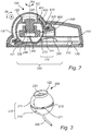
Fig. 2 is a schematic cross-sectional view taken along line A-A of the camera device illustrated inFig.1 . -
Fig. 3 is a perspective view of a camera unit. -
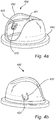
Fig. 4a is a perspective view of a cover. -
Fig. 4b is a perspective view of the cover ofFig. 4a from a different direction. -
Fig. 5 is a schematic cross-sectional view taken along line B-B of the camera device illustrated inFig. 1 . -
Fig. 6a is a schematic cross-sectional detail view illustrating a section of the camera device illustrated inFig. 5 . -
Fig. 6b is a schematic cross-sectional view illustrating the detail ofFig. 6a in a state after the camera device having been subjected to an external force. - The present invention will now be described more fully hereinafter with reference to the accompanying drawings, in which currently preferred embodiments of the invention are shown. This invention may, however, be embodied in many different forms and should not be construed as limited to the embodiments set forth herein; rather, these embodiments are provided for thoroughness and completeness, and to fully convey the scope of the invention to the skilled person.
- A
camera device 100 will in the following be described with reference to the figures. -
Fig. 1 illustrates an embodiment of thecamera device 100. The disclosed embodiment comprises abase member 130, ahousing 110 and adome window 120 enclosing a camera unit 200 (shown inFig. 2 ). -
Fig. 2 discloses a cross sectional view of thecamera device 100 disclosed inFig. 1 . Thehousing 110 accommodates thebase member 130, thecamera unit 200 and acover 400. Thehousing 110 further supports thedome window 120. - The
camera unit 200 is also shown inFig. 3 and comprises anouter shell 210. Theouter shell 210 has a spherical shape and is provided with anequatorial groove 270. Theouter shell 210 may be formed such that it comprises afront shell 211 and arear shell 212. Thefront shell 211 may be made of resin. Therear shell 212 may be made of resin. - The
front shell 211 and therear shell 212 are separated by theequatorial groove 270. Theequatorial groove 270 has a start and an end, that is, thegroove 270 has a limited extension. The section separating the end and the start of the groove forms astop 271. Thestop 271 may be formed by an integral part connecting thefront shell 211 with therear shell 212. - The
camera unit 200 also comprises anoptical unit 220 aligned with an optical axis OA. - In the shown embodiment, the camera unit further comprises an image printed circuit board, PCB, 240 and an
image sensor 250. Theimage sensor 250 is typically of a rectangular shape. As is evident from the figure, thecamera unit 200 is attached to acable 260. The cable connects thecamera unit 220 to a main unit (not shown). Thecable 260 may be arranged to connect the image printedcircuit board 240 to control printedcircuit board 310. - The
base member 130 comprises aseating 131 arranged for reception of thecamera unit 200. Theseating 131 has a semi spherical shape corresponding to the spherical shape of thecamera unit 200. Thebase member 130 may be made of resin. Alternatively, thebase member 130 may be made of metal. - The
cover 400, which is also shown inFigs. 4a, b , is provided with alug 420 supporting apivot 410. Thecover 400 has a semi spherical shape corresponding to the spherical shape of thecamera unit 200. Thecover 400 further comprises anaperture 450 for providing a free line of sight for thecamera unit 200. Thecover 400 may be made of resin. - The
camera unit 200 is arranged between theseating 130 and thecover 400. In an assembled state, thepivot 410 is received by theequatorial groove 270. Thecamera unit 200 is arranged such that thecover 400 and theseating 131 of thebase member 130 is pressed against theouter shell 210 of thecamera unit 200 from opposing sides thereof. By pressing thecamera unit 200 from opposing sides thereof, frictional forces are generated maintainingcamera unit 200 in a desired orientation. The frictional forces formed between thecamera unit 200 and thecover 400 as well as between thecamera unit 200 and theseating 131 prevent thecamera unit 200 from becoming accidentally redirected when subjected to small external forces, such as vibrations. - By properly balancing the frictional forces, it may be ensured that a user may manually rotate or tilt the
camera unit 200 for orientation thereof. - When the
base member 130 is made of resin, thefront shell 211 may be made of metal. Generally, if the parts that cause friction between each other, are both made of metal, the friction force formed therebetween will be large, and in such a case it may be difficult for a user to rotate or tilt thecamera unit 200. - The
pivot 410 has a conical or frustoconical shape. Theequatorial groove 270 of thecamera unit 200 has a corresponding cross-section. Hence, theequatorial groove 270 is arranged to receive thepivot 410 of thecover 400. The conical or truncated conical shape of thepivot 410 may have a circular base. - The conical or frustoconical shape of the
pivot 410 in combination with the corresponding cross-section of thegroove 270 enables thepivot 410 to be relative rotatable inside thegroove 270 when received thereby. Thus, thepivot 410 enables tilting of thecamera unit 200 about a well-defined tilting axis TA when thepivot 410 is received by theequatorial groove 270. By the provision of atiltable camera unit 200, thecamera device 100 can capture images in a wide range. Thepivot 410 in connection with theequatorial groove 270 may be arranged to provide a tilting range of at least 90 degrees. - The
aperture 450 of thecover 400 may have an extension as to provide a free line of sight for thecamera unit 200 within a tilting range of at least 90 degrees. - The
pivot 410 and theequatorial groove 270 may be configured to cooperate such that thecamera unit 200 is rotatable about a rotation axis RA. The rotation axis RA may coincide with the optical axis OA of thecamera unit 200. Theequatorial groove 270 may be configured to restrict a rotating range of thecamera unit 200 to less than 360 degrees. More specifically, the equatorial groove extends between a start and an end with astop 271 separating the end of the groove from the start of the groove. Thus, when the camera unit is rotated in either direction, thestop 271 will ultimately be brought into engagement with thepivot 410 thereby preventing further rotation. By preventing thecamera unit 200 from unlimited rotation the life span of the camera device may be prolonged. Thecable 260 connecting thecamera unit 200 to the main unit may thus be kept in line with thecamera unit 200 thereby prevented twisting and breaking as a result of an overly rotatedcamera unit 200. - Image sensors of typical camera devices often have a rectangular shape. The rotatability of the
camera unit 200 about the rotation axis RA ensures that the horizon or a corresponding horizonal line of an image captured by the camera device may be adjusted to the rectangular shape of the image sensor. - As can be seen in
Fig. 1 , the camera device may comprise a biasing arrangement configured to press thecover 400 towards thebase member 130. The biasing arrangement comprises anannular cap 600 and aspring member 500. Theannular cap 600 surrounds thecover 400 and is attached to thebase member 130 for instance by means of a thread joint. Theannular cap 600 comprises an upperannular flange 610 which is positioned above a lowerannular flange 440 of thecover 400 with thespring member 500 arranged there between. Thus, by adjustment of the distance between the upperannular flange 610 and the lowerannular flange 440, the biasing effect of the spring member may be controlled. Thespring member 500 may comprise a compression spring or any other type of elastically compressible element. By this configuration, thecamera unit 200 itself is not fixed to theseating 131 and can thus be rotated inside thecover 400. Due to the biasing effect caused by thespring member 500, thecover 400 andseating 131 will be pressed against theouter shell 210 of thecamera unit 200 ensuring that a chosen orientation of thecamera unit 200 may be maintained over time. A user may still set thecamera unit 200 in a new orientation by application of a force, for instance for tilting, sufficient for overcoming the frictional forces caused by the biasing effect of thespring member 500. - As is evident from
Figs. 4a-4b thecover 400 may be provided with aninner projection arrangement 401. Theprojection arrangement 401 may comprise an elongated ridge extending along an inner surface of thecover 400. Theprojection arrangement 401 may have a latitudinal extension along the inner surface of thecover 400. In some embodiments theprojection arrangement 401 may be formed as several projection dots distributed along a path on the inside of thecover 401. - The provision of the
inner projection arrangement 401 on the inner surface of thecover 400 may ensure a well-defined area of contact between thecover 400 and theouter shell 210 of thecamera unit 200 facilitating proper balancing of the pressure force holding the camera unit in place. -
Fig. 5 illustrates another schematic cross-sectional view of the camera device disclosed inFig. 1 . The camera device is subjected to an external force illustrated by arrow F. The external force F may be in the form of a sudden impact. In the shown embodiment, the external force F is applied to thecamera device 100 via thedome window 120. If external force F is of sufficient magnitude, the dome window is configured to be displaced or be deformed such that it engages thecamera unit 200. In the shown embodiment, thedome window 120 is configured to engage a protrudingsection 122 of thecamera unit 200. It is to be noted that the figure only discloses an embodiment, and that the protrudingsection 122 may be a different portion of thecamera unit 200. - When the external force F of sufficient magnitude is applied to the
camera device 100, the force may thus be transferred to thecamera unit 200 when thedome window 120 engages thefront shell 211 of thecamera unit 200. The force is transferred to from thefront shell 211 to therear shell 212. As a consequence, therear shell 212 will be deformed, causing anupper groove surface 273 of theequatorial groove 270 to be pressed against thepivot 410 which will cause thelug 420 of thecover 400 to be laterally displaced thereby disengaging thepivot 410 from theequatorial groove 270. By causing controlled disengagement of thepivot 410 from thegroove 270 in the event of the camera device being subject to an external force of sufficient magnitude, damage of camera components, such as thepivot 410, may be prevented. - The mechanism of the
lug 420 and how it is laterally displaceable will now be described more in detail with reference toFigs. 6a-6b . - The
pivot 410 is arranged on thelug 420 adjoining thecover 400 via a lug transition and defined by a slit 430 (more clearly illustrated inFig. 4b ). Thus, thelug 420 is laterally displaced in a direction D being parallel with the tilting axis TA. Thelug 420 becomes laterally displaced in response to thepivot 410 being subjected to a force having a component in said direction D. -
Fig. 6a shows the position of thelug 420 before a force is subjected to thepivot 410. As is evident from the figure a gap is formed between abottom surface 272 of theequatorial groove 270 and atip surface 411 of thepivot 410. Thus, there is no frictional force occurring between thebottom surface 272 and thetip surface 411 when rotating or tilting. Accordingly, the force needed for tilting or rotating is only the friction force of the between theouter shell 210 and the seating131 and between theouter shell 210 and thecover 400. - The
lug 420 may comprise a weakened portion with a first thickness T1. Thecover 400 may have a wall thickness WT. The first thickness T1 of the weakened portion may be less than the wall thickness WT of thecover 400. - The lug may be integrally formed with the
cover 400 such that the weakened portion adjoins thecover 400 via thelug transition 421 which is formed with a radius such as to form a smooth and gradual transition from thelug 420 to thecover 400. The absence of sharp corners in thelug transition 421 reduces the risk of fracture during the lateral displacement of thelug 420. - The
pivot 410 is formed integral with thelug 420 and apivot transition 422 between thepivot 410 and thelug 420 is formed with a radius such as to form a smooth and gradual transition from thelug 420 to thepivot 410. The absence of sharp corners in thepivot transition 422 reduces the risk of fracture during the lateral displacement of thelug 420. - The force applied to the
pivot 410 and having a component in the direction D may as explained above originate from an impact force F being applied to thecamera device 100. - More specifically, when the
rear shell 212 of thecamera unit 200 is displaced or deformed as a consequence of thedome window 120 engaging thecamera unit 200, theupper groove surface 273 of theequatorial groove 270 will be pressed downwards and thereby engage thepivot 412. Thepivot 410 has, as mentioned above, a conical or frustoconical cross-section and thegroove 270 has a corresponding shape, so as to be able to receive thepivot 410. Thus, the downward pressing of theupper groove surface 273 will result in a force acting on the pivot having a component in the direction D. - As is evident from
Fig. 6b , thelug 420 and thereby thepivot 410 is displaceable in the direction D, being in a lateral direction away from the camera unit, in response to being subjected to a force having a component in the direction D. - By such a displaceability of the
lug 420, thecamera unit 200 is thus disengaged from the cover and thepivot 410 supported thereby when an external force of sufficient magnitude is applied to the camera device via thedome window 120. Hereby, the risk of fracture or damaging of camera components, such as thelug 420 or thepivot 410, is eliminated or at least substantially reduced. - An external force of sufficient magnitude applied to the
camera device 100 may correspond to the camera device being subjected to a kick or a punch. - In some embodiments when the
cover 400 is made of a resin material thelug 420 may be elastically laterally displaceable. - In some embodiments, the
housing 110 may support thedome window 120, and accommodate thebase member 130, and thecamera unit 200 and thecover 400. In some embodiments,camera unit 200 may comprise a varifocal lens. - The person skilled in the art realizes that the present invention by no means is limited to the preferred embodiments described above. On the contrary, many modifications and variations are possible within the scope of the appended claims.
- Additionally, variations to the disclosed embodiments can be understood and effected by the skilled person in practicing the claimed invention, from a study of the drawings, the disclosure, and the appended claims. In the claims, the word "comprising" does not exclude other elements or steps, and the indefinite article "a" or "an" does not exclude a plurality. The mere fact that certain measures are recited in mutually different dependent claims does not indicate that a combination of these measured cannot be used to advantage.
Claims (13)
- A camera device (100) comprising,
a camera unit (200) comprising an outer shell (210) having a spherical shape and being provided with an equatorial groove (270) having a start and an end,
a base member provided (130) with a seating (131),
a cover (400) provided with a pivot (410) defining a tilting axis (TA) and an aperture (450) for providing a free line of sight for the camera unit (200),
wherein the camera unit (200) is arranged between the seating (131) and the cover (400) such that the pivot (410) is received by the equatorial groove (270) and such that the cover (400) and the seating (131) of the base member (130) are pressed against the outer shell (210) of the camera unit (200) from opposing sides thereof,
wherein the pivot (410) has a conical or frustoconical shape, and the equatorial groove (270) has a corresponding cross section,
wherein the pivot (410) is arranged on a lug (420) adjoining the cover (400) via a lug transition and defined by a slit (430) such that the lug is laterally displaceable in a direction (D) parallel with the tilting axis (TA) in response to the pivot (410) being subjected to a force having a component in said direction (D),
wherein the pivot (410) is formed integral with the lug (420) and wherein a pivot transition (412) between the pivot (410) and the lug (420) is formed with a radius. - The camera device (100) according to claim 1, wherein the cover (400) is provided with an inner projection arrangement (401) and wherein the camera unit (200) is arranged between the seating (131) and the cover (400) such that the inner projection arrangement (401) of the cover (400) and the seating (131) of the base member (130) is pressed against the outer shell (210) of the camera unit (200) from opposing sides thereof.
- The camera device (100) according to claim 1 or 2, wherein the camera unit (200) is tiltable about the tilting axis (TA) and wherein the aperture (450) of the cover (400) has an extension as to provide a free line of sight for the camera unit (200) within a tilting range of at least 90 degrees.
- The camera device (100) according to any one of the previous claims, wherein the camera unit (200) is rotatable about a rotation axis (RA) coinciding with an optical axis (OA) of the camera unit (200), wherein the pivot (410) and the equatorial groove (270) in cooperation are configured to restrict a rotating range of the camera unit (200) to less than 360 degrees.
- The camera device (100) according to any one of the previous claims, wherein the conical or frustoconical conical shape of the pivot (410) has a circular base.
- The camera device (100) according to any one of the previous claims, wherein the inner projection arrangement (401) comprises an elongated ridge extending along an inner surface of the cover (400).
- The camera device (100) according to any one of the previous claims, wherein the projection arrangement (401) has a latitudinal extension along an inner surface of the cover (400).
- The camera device (100) according to any one of the previous claims, further comprising a dome window (120) which partly encloses the cover (400) and the camera unit (200), wherein the dome window (120), in response to being subjected to an external force (F), is configured to be displaced and to engage a protruding section (122) of the camera unit (200).
- The camera device (100) according to claim 8, further comprising a housing (110) supporting the dome window (120) and accommodating the base member (130), the camera unit (200) and the cover (400).
- The camera device (100) according to any one of the previous claims, in which the lug (420) comprises a weakened portion with a first thickness (T1) and the cover has a wall thickness (WT), wherein the first thickness (T1) is less than the wall thickness (WT).
- The camera device (100) according to claim 10, wherein the lug (420) is integrally formed with the cover (400) such that the weakened portion adjoins the cover (400) via the lug transition (421) which is formed with a radius.
- The camera device (100) according to any one of the previous claims, further comprising a biasing arrangement (600) comprising a spring member (500), wherein the biasing arrangement (600) is configured to press the cover towards the base member (131) against the action of the spring member (500).
- The camera device (100) according to any one of the previous claims, wherein the camera unit (200) comprises a varifocal lens.
Priority Applications (6)
| Application Number | Priority Date | Filing Date | Title |
|---|---|---|---|
| EP19211503.8A EP3828846B1 (en) | 2019-11-26 | 2019-11-26 | Camera device |
| KR1020200125161A KR102394989B1 (en) | 2019-11-26 | 2020-09-25 | Camera device |
| US17/037,835 US11128784B2 (en) | 2019-11-26 | 2020-09-30 | Camera device |
| TW109135441A TWI794657B (en) | 2019-11-26 | 2020-10-14 | Camera device |
| JP2020192457A JP7069278B2 (en) | 2019-11-26 | 2020-11-19 | Camera device |
| CN202011308206.2A CN112954148B (en) | 2019-11-26 | 2020-11-20 | Camera apparatus |
Applications Claiming Priority (1)
| Application Number | Priority Date | Filing Date | Title |
|---|---|---|---|
| EP19211503.8A EP3828846B1 (en) | 2019-11-26 | 2019-11-26 | Camera device |
Publications (2)
| Publication Number | Publication Date |
|---|---|
| EP3828846A1 true EP3828846A1 (en) | 2021-06-02 |
| EP3828846B1 EP3828846B1 (en) | 2022-07-13 |
Family
ID=68696343
Family Applications (1)
| Application Number | Title | Priority Date | Filing Date |
|---|---|---|---|
| EP19211503.8A Active EP3828846B1 (en) | 2019-11-26 | 2019-11-26 | Camera device |
Country Status (6)
| Country | Link |
|---|---|
| US (1) | US11128784B2 (en) |
| EP (1) | EP3828846B1 (en) |
| JP (1) | JP7069278B2 (en) |
| KR (1) | KR102394989B1 (en) |
| CN (1) | CN112954148B (en) |
| TW (1) | TWI794657B (en) |
Citations (5)
| Publication number | Priority date | Publication date | Assignee | Title |
|---|---|---|---|---|
| US20070217782A1 (en) * | 2006-03-17 | 2007-09-20 | Mccutchen David | Spinning camera enclosure for environmental protection |
| US20110310293A1 (en) * | 2009-02-27 | 2011-12-22 | Panasonic Corporation | Dome-shaped camera |
| US20120188441A1 (en) * | 2010-07-07 | 2012-07-26 | Panasonic Corporation | Camera drive device |
| WO2018158608A1 (en) * | 2017-02-28 | 2018-09-07 | Doma Automation S.R.L. | Device for photographing objects |
| WO2018223230A1 (en) * | 2017-06-05 | 2018-12-13 | Avigilon Corporation | Spherical camera |
Family Cites Families (23)
| Publication number | Priority date | Publication date | Assignee | Title |
|---|---|---|---|---|
| US6357936B1 (en) | 1999-12-27 | 2002-03-19 | Elbex Video Ltd. | Holder for a ball-shaped television camera or a TV camera case |
| JP2001318423A (en) | 2000-05-12 | 2001-11-16 | Nippon Sheet Glass Co Ltd | Protective cover for camera |
| JP3954313B2 (en) * | 2001-01-23 | 2007-08-08 | 矢崎総業株式会社 | Connector damage prevention structure |
| JP4181448B2 (en) | 2003-05-26 | 2008-11-12 | ティーオーエー株式会社 | Dome-type camera cover, dome-type camera and method of assembling the same |
| JP4771827B2 (en) * | 2006-02-21 | 2011-09-14 | 三洋電機株式会社 | Surveillance camera |
| US7614804B2 (en) * | 2006-08-29 | 2009-11-10 | Nuvico, Inc. | Security camera |
| JP2009135723A (en) | 2007-11-30 | 2009-06-18 | Victor Co Of Japan Ltd | Monitoring camera device |
| JP2010081545A (en) * | 2008-09-29 | 2010-04-08 | Canon Inc | Wall-mounted monitoring camera system, and monitoring camera housing case |
| US9237317B2 (en) * | 2009-05-02 | 2016-01-12 | Steven J. Hollinger | Throwable camera and network for operating the same |
| US20110064403A1 (en) * | 2009-09-16 | 2011-03-17 | Victor Company Of Japan, Ltd. | Domed-shaped camera |
| JP5347901B2 (en) * | 2009-10-21 | 2013-11-20 | ソニー株式会社 | Monitoring device |
| JP5587105B2 (en) * | 2010-09-09 | 2014-09-10 | キヤノン株式会社 | Imaging device |
| KR20130016672A (en) * | 2011-08-08 | 2013-02-18 | 삼성테크윈 주식회사 | Monitoring camera |
| EP2657762B1 (en) * | 2012-04-25 | 2014-03-26 | Axis AB | Top cover assembly for a monitoring camera |
| WO2014076959A1 (en) * | 2012-11-16 | 2014-05-22 | パナソニック株式会社 | Camera drive device |
| TWM464697U (en) * | 2013-05-22 | 2013-11-01 | Hunt Electronic Co Ltd | Camera adjustment assembly |
| JP2014236318A (en) | 2013-05-31 | 2014-12-15 | キヤノン株式会社 | Imaging device |
| JP6094511B2 (en) * | 2014-02-25 | 2017-03-15 | ソニー株式会社 | Imaging device and imaging apparatus |
| KR102059697B1 (en) * | 2014-08-14 | 2019-12-26 | 한화테크윈 주식회사 | Dome camera device |
| JP6494243B2 (en) * | 2014-10-28 | 2019-04-03 | キヤノン株式会社 | Imaging device |
| EP3378704B1 (en) * | 2017-03-20 | 2019-10-16 | Veoneer Sweden AB | An imaging system for a motor vehicle |
| CN107094226B (en) | 2017-06-05 | 2019-05-17 | 广州市邻里智能化工程有限公司 | A kind of ball-type security monitoring camera |
| JP6861595B2 (en) * | 2017-08-03 | 2021-04-21 | 三菱電機株式会社 | Surveillance camera |
-
2019
- 2019-11-26 EP EP19211503.8A patent/EP3828846B1/en active Active
-
2020
- 2020-09-25 KR KR1020200125161A patent/KR102394989B1/en active Active
- 2020-09-30 US US17/037,835 patent/US11128784B2/en active Active
- 2020-10-14 TW TW109135441A patent/TWI794657B/en active
- 2020-11-19 JP JP2020192457A patent/JP7069278B2/en active Active
- 2020-11-20 CN CN202011308206.2A patent/CN112954148B/en active Active
Patent Citations (5)
| Publication number | Priority date | Publication date | Assignee | Title |
|---|---|---|---|---|
| US20070217782A1 (en) * | 2006-03-17 | 2007-09-20 | Mccutchen David | Spinning camera enclosure for environmental protection |
| US20110310293A1 (en) * | 2009-02-27 | 2011-12-22 | Panasonic Corporation | Dome-shaped camera |
| US20120188441A1 (en) * | 2010-07-07 | 2012-07-26 | Panasonic Corporation | Camera drive device |
| WO2018158608A1 (en) * | 2017-02-28 | 2018-09-07 | Doma Automation S.R.L. | Device for photographing objects |
| WO2018223230A1 (en) * | 2017-06-05 | 2018-12-13 | Avigilon Corporation | Spherical camera |
Also Published As
| Publication number | Publication date |
|---|---|
| TW202132887A (en) | 2021-09-01 |
| EP3828846B1 (en) | 2022-07-13 |
| KR102394989B1 (en) | 2022-05-04 |
| CN112954148A (en) | 2021-06-11 |
| TWI794657B (en) | 2023-03-01 |
| US20210160404A1 (en) | 2021-05-27 |
| KR20210065029A (en) | 2021-06-03 |
| US11128784B2 (en) | 2021-09-21 |
| JP7069278B2 (en) | 2022-05-17 |
| JP2021099159A (en) | 2021-07-01 |
| CN112954148B (en) | 2022-11-18 |
Similar Documents
| Publication | Publication Date | Title |
|---|---|---|
| US8891005B2 (en) | Imaging apparatus | |
| EP2657762B1 (en) | Top cover assembly for a monitoring camera | |
| US8189045B2 (en) | Surveillance camera | |
| US7170560B2 (en) | Surveillance camera with impact absorbing structure | |
| US8164686B2 (en) | Surveillance television camera | |
| US11553122B2 (en) | Image capturing apparatus wherein impact applied to a dome is absorbed based on gap distancing | |
| US11128784B2 (en) | Camera device | |
| US20210229605A1 (en) | Vehicle Image-taking Device and Vehicle | |
| CN113315889A (en) | Image pickup apparatus | |
| CN213213629U (en) | Camera blocking devices, cameras and vehicles | |
| JP6531291B2 (en) | Mounting aid and imaging device unit | |
| KR100775203B1 (en) | Dome camera | |
| KR100492121B1 (en) | Dome shaped closed circuit television camera assembly | |
| JP2012094970A (en) | Television camera device | |
| CN112283510B (en) | Camera device and installation component and base thereof | |
| KR100913392B1 (en) | Camera tilting device | |
| JP2009216792A (en) | Lens device for monitoring and camera for monitoring | |
| JP3894451B2 (en) | Surveillance camera device | |
| AU2020210270A1 (en) | Camera device and photographing system including the same | |
| KR102707072B1 (en) | Dome type camera for easily adjusting view field direction | |
| CN213177413U (en) | Camera base | |
| CN213934503U (en) | Outdoor camera plastic case | |
| RU2321070C1 (en) | Television camera in the box of smoke-based fire alarm | |
| JP2025062671A (en) | Wearable Camera | |
| KR20060010150A (en) | Surveillance Camera Case |
Legal Events
| Date | Code | Title | Description |
|---|---|---|---|
| PUAI | Public reference made under article 153(3) epc to a published international application that has entered the european phase |
Free format text: ORIGINAL CODE: 0009012 |
|
| STAA | Information on the status of an ep patent application or granted ep patent |
Free format text: STATUS: REQUEST FOR EXAMINATION WAS MADE |
|
| 17P | Request for examination filed |
Effective date: 20200930 |
|
| AK | Designated contracting states |
Kind code of ref document: A1 Designated state(s): AL AT BE BG CH CY CZ DE DK EE ES FI FR GB GR HR HU IE IS IT LI LT LU LV MC MK MT NL NO PL PT RO RS SE SI SK SM TR |
|
| GRAP | Despatch of communication of intention to grant a patent |
Free format text: ORIGINAL CODE: EPIDOSNIGR1 |
|
| STAA | Information on the status of an ep patent application or granted ep patent |
Free format text: STATUS: GRANT OF PATENT IS INTENDED |
|
| RIC1 | Information provided on ipc code assigned before grant |
Ipc: G03B 17/56 20210101ALI20220228BHEP Ipc: H04N 5/225 20060101ALI20220228BHEP Ipc: G03B 17/02 20210101ALI20220228BHEP Ipc: G08B 13/196 20060101AFI20220228BHEP |
|
| INTG | Intention to grant announced |
Effective date: 20220405 |
|
| GRAS | Grant fee paid |
Free format text: ORIGINAL CODE: EPIDOSNIGR3 |
|
| GRAA | (expected) grant |
Free format text: ORIGINAL CODE: 0009210 |
|
| STAA | Information on the status of an ep patent application or granted ep patent |
Free format text: STATUS: THE PATENT HAS BEEN GRANTED |
|
| AK | Designated contracting states |
Kind code of ref document: B1 Designated state(s): AL AT BE BG CH CY CZ DE DK EE ES FI FR GB GR HR HU IE IS IT LI LT LU LV MC MK MT NL NO PL PT RO RS SE SI SK SM TR |
|
| REG | Reference to a national code |
Ref country code: CH Ref legal event code: EP |
|
| REG | Reference to a national code |
Ref country code: DE Ref legal event code: R096 Ref document number: 602019016941 Country of ref document: DE |
|
| REG | Reference to a national code |
Ref country code: AT Ref legal event code: REF Ref document number: 1504675 Country of ref document: AT Kind code of ref document: T Effective date: 20220815 |
|
| REG | Reference to a national code |
Ref country code: IE Ref legal event code: FG4D |
|
| REG | Reference to a national code |
Ref country code: SE Ref legal event code: TRGR |
|
| REG | Reference to a national code |
Ref country code: LT Ref legal event code: MG9D |
|
| REG | Reference to a national code |
Ref country code: NL Ref legal event code: MP Effective date: 20220713 |
|
| PG25 | Lapsed in a contracting state [announced via postgrant information from national office to epo] |
Ref country code: RS Free format text: LAPSE BECAUSE OF FAILURE TO SUBMIT A TRANSLATION OF THE DESCRIPTION OR TO PAY THE FEE WITHIN THE PRESCRIBED TIME-LIMIT Effective date: 20220713 Ref country code: PT Free format text: LAPSE BECAUSE OF FAILURE TO SUBMIT A TRANSLATION OF THE DESCRIPTION OR TO PAY THE FEE WITHIN THE PRESCRIBED TIME-LIMIT Effective date: 20221114 Ref country code: NO Free format text: LAPSE BECAUSE OF FAILURE TO SUBMIT A TRANSLATION OF THE DESCRIPTION OR TO PAY THE FEE WITHIN THE PRESCRIBED TIME-LIMIT Effective date: 20221013 Ref country code: NL Free format text: LAPSE BECAUSE OF FAILURE TO SUBMIT A TRANSLATION OF THE DESCRIPTION OR TO PAY THE FEE WITHIN THE PRESCRIBED TIME-LIMIT Effective date: 20220713 Ref country code: LV Free format text: LAPSE BECAUSE OF FAILURE TO SUBMIT A TRANSLATION OF THE DESCRIPTION OR TO PAY THE FEE WITHIN THE PRESCRIBED TIME-LIMIT Effective date: 20220713 Ref country code: LT Free format text: LAPSE BECAUSE OF FAILURE TO SUBMIT A TRANSLATION OF THE DESCRIPTION OR TO PAY THE FEE WITHIN THE PRESCRIBED TIME-LIMIT Effective date: 20220713 Ref country code: FI Free format text: LAPSE BECAUSE OF FAILURE TO SUBMIT A TRANSLATION OF THE DESCRIPTION OR TO PAY THE FEE WITHIN THE PRESCRIBED TIME-LIMIT Effective date: 20220713 Ref country code: ES Free format text: LAPSE BECAUSE OF FAILURE TO SUBMIT A TRANSLATION OF THE DESCRIPTION OR TO PAY THE FEE WITHIN THE PRESCRIBED TIME-LIMIT Effective date: 20220713 |
|
| REG | Reference to a national code |
Ref country code: AT Ref legal event code: MK05 Ref document number: 1504675 Country of ref document: AT Kind code of ref document: T Effective date: 20220713 |
|
| PG25 | Lapsed in a contracting state [announced via postgrant information from national office to epo] |
Ref country code: PL Free format text: LAPSE BECAUSE OF FAILURE TO SUBMIT A TRANSLATION OF THE DESCRIPTION OR TO PAY THE FEE WITHIN THE PRESCRIBED TIME-LIMIT Effective date: 20220713 Ref country code: IS Free format text: LAPSE BECAUSE OF FAILURE TO SUBMIT A TRANSLATION OF THE DESCRIPTION OR TO PAY THE FEE WITHIN THE PRESCRIBED TIME-LIMIT Effective date: 20221113 Ref country code: HR Free format text: LAPSE BECAUSE OF FAILURE TO SUBMIT A TRANSLATION OF THE DESCRIPTION OR TO PAY THE FEE WITHIN THE PRESCRIBED TIME-LIMIT Effective date: 20220713 Ref country code: GR Free format text: LAPSE BECAUSE OF FAILURE TO SUBMIT A TRANSLATION OF THE DESCRIPTION OR TO PAY THE FEE WITHIN THE PRESCRIBED TIME-LIMIT Effective date: 20221014 |
|
| REG | Reference to a national code |
Ref country code: DE Ref legal event code: R097 Ref document number: 602019016941 Country of ref document: DE |
|
| PG25 | Lapsed in a contracting state [announced via postgrant information from national office to epo] |
Ref country code: SM Free format text: LAPSE BECAUSE OF FAILURE TO SUBMIT A TRANSLATION OF THE DESCRIPTION OR TO PAY THE FEE WITHIN THE PRESCRIBED TIME-LIMIT Effective date: 20220713 Ref country code: RO Free format text: LAPSE BECAUSE OF FAILURE TO SUBMIT A TRANSLATION OF THE DESCRIPTION OR TO PAY THE FEE WITHIN THE PRESCRIBED TIME-LIMIT Effective date: 20220713 Ref country code: DK Free format text: LAPSE BECAUSE OF FAILURE TO SUBMIT A TRANSLATION OF THE DESCRIPTION OR TO PAY THE FEE WITHIN THE PRESCRIBED TIME-LIMIT Effective date: 20220713 Ref country code: CZ Free format text: LAPSE BECAUSE OF FAILURE TO SUBMIT A TRANSLATION OF THE DESCRIPTION OR TO PAY THE FEE WITHIN THE PRESCRIBED TIME-LIMIT Effective date: 20220713 Ref country code: AT Free format text: LAPSE BECAUSE OF FAILURE TO SUBMIT A TRANSLATION OF THE DESCRIPTION OR TO PAY THE FEE WITHIN THE PRESCRIBED TIME-LIMIT Effective date: 20220713 |
|
| PLBE | No opposition filed within time limit |
Free format text: ORIGINAL CODE: 0009261 |
|
| STAA | Information on the status of an ep patent application or granted ep patent |
Free format text: STATUS: NO OPPOSITION FILED WITHIN TIME LIMIT |
|
| PG25 | Lapsed in a contracting state [announced via postgrant information from national office to epo] |
Ref country code: SK Free format text: LAPSE BECAUSE OF FAILURE TO SUBMIT A TRANSLATION OF THE DESCRIPTION OR TO PAY THE FEE WITHIN THE PRESCRIBED TIME-LIMIT Effective date: 20220713 Ref country code: EE Free format text: LAPSE BECAUSE OF FAILURE TO SUBMIT A TRANSLATION OF THE DESCRIPTION OR TO PAY THE FEE WITHIN THE PRESCRIBED TIME-LIMIT Effective date: 20220713 |
|
| P01 | Opt-out of the competence of the unified patent court (upc) registered |
Effective date: 20230505 |
|
| 26N | No opposition filed |
Effective date: 20230414 |
|
| PG25 | Lapsed in a contracting state [announced via postgrant information from national office to epo] |
Ref country code: MC Free format text: LAPSE BECAUSE OF FAILURE TO SUBMIT A TRANSLATION OF THE DESCRIPTION OR TO PAY THE FEE WITHIN THE PRESCRIBED TIME-LIMIT Effective date: 20220713 Ref country code: AL Free format text: LAPSE BECAUSE OF FAILURE TO SUBMIT A TRANSLATION OF THE DESCRIPTION OR TO PAY THE FEE WITHIN THE PRESCRIBED TIME-LIMIT Effective date: 20220713 |
|
| REG | Reference to a national code |
Ref country code: CH Ref legal event code: PL |
|
| REG | Reference to a national code |
Ref country code: BE Ref legal event code: MM Effective date: 20221130 |
|
| PG25 | Lapsed in a contracting state [announced via postgrant information from national office to epo] |
Ref country code: LI Free format text: LAPSE BECAUSE OF NON-PAYMENT OF DUE FEES Effective date: 20221130 Ref country code: CH Free format text: LAPSE BECAUSE OF NON-PAYMENT OF DUE FEES Effective date: 20221130 |
|
| PG25 | Lapsed in a contracting state [announced via postgrant information from national office to epo] |
Ref country code: SI Free format text: LAPSE BECAUSE OF FAILURE TO SUBMIT A TRANSLATION OF THE DESCRIPTION OR TO PAY THE FEE WITHIN THE PRESCRIBED TIME-LIMIT Effective date: 20220713 Ref country code: LU Free format text: LAPSE BECAUSE OF NON-PAYMENT OF DUE FEES Effective date: 20221126 |
|
| PG25 | Lapsed in a contracting state [announced via postgrant information from national office to epo] |
Ref country code: IE Free format text: LAPSE BECAUSE OF NON-PAYMENT OF DUE FEES Effective date: 20221126 |
|
| PG25 | Lapsed in a contracting state [announced via postgrant information from national office to epo] |
Ref country code: BE Free format text: LAPSE BECAUSE OF NON-PAYMENT OF DUE FEES Effective date: 20221130 |
|
| PG25 | Lapsed in a contracting state [announced via postgrant information from national office to epo] |
Ref country code: IT Free format text: LAPSE BECAUSE OF FAILURE TO SUBMIT A TRANSLATION OF THE DESCRIPTION OR TO PAY THE FEE WITHIN THE PRESCRIBED TIME-LIMIT Effective date: 20220713 |
|
| PG25 | Lapsed in a contracting state [announced via postgrant information from national office to epo] |
Ref country code: CY Free format text: LAPSE BECAUSE OF FAILURE TO SUBMIT A TRANSLATION OF THE DESCRIPTION OR TO PAY THE FEE WITHIN THE PRESCRIBED TIME-LIMIT Effective date: 20220713 |
|
| PG25 | Lapsed in a contracting state [announced via postgrant information from national office to epo] |
Ref country code: MK Free format text: LAPSE BECAUSE OF FAILURE TO SUBMIT A TRANSLATION OF THE DESCRIPTION OR TO PAY THE FEE WITHIN THE PRESCRIBED TIME-LIMIT Effective date: 20220713 Ref country code: HU Free format text: LAPSE BECAUSE OF FAILURE TO SUBMIT A TRANSLATION OF THE DESCRIPTION OR TO PAY THE FEE WITHIN THE PRESCRIBED TIME-LIMIT; INVALID AB INITIO Effective date: 20191126 |
|
| PG25 | Lapsed in a contracting state [announced via postgrant information from national office to epo] |
Ref country code: TR Free format text: LAPSE BECAUSE OF FAILURE TO SUBMIT A TRANSLATION OF THE DESCRIPTION OR TO PAY THE FEE WITHIN THE PRESCRIBED TIME-LIMIT Effective date: 20220713 |
|
| PG25 | Lapsed in a contracting state [announced via postgrant information from national office to epo] |
Ref country code: BG Free format text: LAPSE BECAUSE OF FAILURE TO SUBMIT A TRANSLATION OF THE DESCRIPTION OR TO PAY THE FEE WITHIN THE PRESCRIBED TIME-LIMIT Effective date: 20220713 |
|
| PG25 | Lapsed in a contracting state [announced via postgrant information from national office to epo] |
Ref country code: MT Free format text: LAPSE BECAUSE OF FAILURE TO SUBMIT A TRANSLATION OF THE DESCRIPTION OR TO PAY THE FEE WITHIN THE PRESCRIBED TIME-LIMIT Effective date: 20220713 |
|
| PGFP | Annual fee paid to national office [announced via postgrant information from national office to epo] |
Ref country code: DE Payment date: 20251022 Year of fee payment: 7 |
|
| PGFP | Annual fee paid to national office [announced via postgrant information from national office to epo] |
Ref country code: GB Payment date: 20251023 Year of fee payment: 7 |
|
| PGFP | Annual fee paid to national office [announced via postgrant information from national office to epo] |
Ref country code: FR Payment date: 20251023 Year of fee payment: 7 |
|
| PGFP | Annual fee paid to national office [announced via postgrant information from national office to epo] |
Ref country code: SE Payment date: 20251022 Year of fee payment: 7 |