EP3828487A1 - Process and apparatus for the production of liquid nitrogen - Google Patents
Process and apparatus for the production of liquid nitrogen Download PDFInfo
- Publication number
- EP3828487A1 EP3828487A1 EP20210161.4A EP20210161A EP3828487A1 EP 3828487 A1 EP3828487 A1 EP 3828487A1 EP 20210161 A EP20210161 A EP 20210161A EP 3828487 A1 EP3828487 A1 EP 3828487A1
- Authority
- EP
- European Patent Office
- Prior art keywords
- stream
- gas stream
- residual gas
- nitrogen
- liquid nitrogen
- Prior art date
- Legal status (The legal status is an assumption and is not a legal conclusion. Google has not performed a legal analysis and makes no representation as to the accuracy of the status listed.)
- Granted
Links
Images

Classifications
-
- F—MECHANICAL ENGINEERING; LIGHTING; HEATING; WEAPONS; BLASTING
- F25—REFRIGERATION OR COOLING; COMBINED HEATING AND REFRIGERATION SYSTEMS; HEAT PUMP SYSTEMS; MANUFACTURE OR STORAGE OF ICE; LIQUEFACTION SOLIDIFICATION OF GASES
- F25J—LIQUEFACTION, SOLIDIFICATION OR SEPARATION OF GASES OR GASEOUS OR LIQUEFIED GASEOUS MIXTURES BY PRESSURE AND COLD TREATMENT OR BY BRINGING THEM INTO THE SUPERCRITICAL STATE
- F25J3/00—Processes or apparatus for separating the constituents of gaseous or liquefied gaseous mixtures involving the use of liquefaction or solidification
- F25J3/02—Processes or apparatus for separating the constituents of gaseous or liquefied gaseous mixtures involving the use of liquefaction or solidification by rectification, i.e. by continuous interchange of heat and material between a vapour stream and a liquid stream
- F25J3/04—Processes or apparatus for separating the constituents of gaseous or liquefied gaseous mixtures involving the use of liquefaction or solidification by rectification, i.e. by continuous interchange of heat and material between a vapour stream and a liquid stream for air
- F25J3/04006—Providing pressurised feed air or process streams within or from the air fractionation unit
- F25J3/04048—Providing pressurised feed air or process streams within or from the air fractionation unit by compression of cold gaseous streams, e.g. intermediate or oxygen enriched (waste) streams
- F25J3/0406—Providing pressurised feed air or process streams within or from the air fractionation unit by compression of cold gaseous streams, e.g. intermediate or oxygen enriched (waste) streams of nitrogen
-
- F—MECHANICAL ENGINEERING; LIGHTING; HEATING; WEAPONS; BLASTING
- F25—REFRIGERATION OR COOLING; COMBINED HEATING AND REFRIGERATION SYSTEMS; HEAT PUMP SYSTEMS; MANUFACTURE OR STORAGE OF ICE; LIQUEFACTION SOLIDIFICATION OF GASES
- F25J—LIQUEFACTION, SOLIDIFICATION OR SEPARATION OF GASES OR GASEOUS OR LIQUEFIED GASEOUS MIXTURES BY PRESSURE AND COLD TREATMENT OR BY BRINGING THEM INTO THE SUPERCRITICAL STATE
- F25J3/00—Processes or apparatus for separating the constituents of gaseous or liquefied gaseous mixtures involving the use of liquefaction or solidification
- F25J3/02—Processes or apparatus for separating the constituents of gaseous or liquefied gaseous mixtures involving the use of liquefaction or solidification by rectification, i.e. by continuous interchange of heat and material between a vapour stream and a liquid stream
- F25J3/0228—Processes or apparatus for separating the constituents of gaseous or liquefied gaseous mixtures involving the use of liquefaction or solidification by rectification, i.e. by continuous interchange of heat and material between a vapour stream and a liquid stream characterised by the separated product stream
- F25J3/0257—Processes or apparatus for separating the constituents of gaseous or liquefied gaseous mixtures involving the use of liquefaction or solidification by rectification, i.e. by continuous interchange of heat and material between a vapour stream and a liquid stream characterised by the separated product stream separation of nitrogen
-
- F—MECHANICAL ENGINEERING; LIGHTING; HEATING; WEAPONS; BLASTING
- F25—REFRIGERATION OR COOLING; COMBINED HEATING AND REFRIGERATION SYSTEMS; HEAT PUMP SYSTEMS; MANUFACTURE OR STORAGE OF ICE; LIQUEFACTION SOLIDIFICATION OF GASES
- F25J—LIQUEFACTION, SOLIDIFICATION OR SEPARATION OF GASES OR GASEOUS OR LIQUEFIED GASEOUS MIXTURES BY PRESSURE AND COLD TREATMENT OR BY BRINGING THEM INTO THE SUPERCRITICAL STATE
- F25J1/00—Processes or apparatus for liquefying or solidifying gases or gaseous mixtures
- F25J1/0002—Processes or apparatus for liquefying or solidifying gases or gaseous mixtures characterised by the fluid to be liquefied
- F25J1/0012—Primary atmospheric gases, e.g. air
- F25J1/0015—Nitrogen
-
- F—MECHANICAL ENGINEERING; LIGHTING; HEATING; WEAPONS; BLASTING
- F25—REFRIGERATION OR COOLING; COMBINED HEATING AND REFRIGERATION SYSTEMS; HEAT PUMP SYSTEMS; MANUFACTURE OR STORAGE OF ICE; LIQUEFACTION SOLIDIFICATION OF GASES
- F25J—LIQUEFACTION, SOLIDIFICATION OR SEPARATION OF GASES OR GASEOUS OR LIQUEFIED GASEOUS MIXTURES BY PRESSURE AND COLD TREATMENT OR BY BRINGING THEM INTO THE SUPERCRITICAL STATE
- F25J1/00—Processes or apparatus for liquefying or solidifying gases or gaseous mixtures
- F25J1/0002—Processes or apparatus for liquefying or solidifying gases or gaseous mixtures characterised by the fluid to be liquefied
- F25J1/0027—Oxides of carbon, e.g. CO2
-
- F—MECHANICAL ENGINEERING; LIGHTING; HEATING; WEAPONS; BLASTING
- F25—REFRIGERATION OR COOLING; COMBINED HEATING AND REFRIGERATION SYSTEMS; HEAT PUMP SYSTEMS; MANUFACTURE OR STORAGE OF ICE; LIQUEFACTION SOLIDIFICATION OF GASES
- F25J—LIQUEFACTION, SOLIDIFICATION OR SEPARATION OF GASES OR GASEOUS OR LIQUEFIED GASEOUS MIXTURES BY PRESSURE AND COLD TREATMENT OR BY BRINGING THEM INTO THE SUPERCRITICAL STATE
- F25J1/00—Processes or apparatus for liquefying or solidifying gases or gaseous mixtures
- F25J1/02—Processes or apparatus for liquefying or solidifying gases or gaseous mixtures requiring the use of refrigeration, e.g. of helium or hydrogen ; Details and kind of the refrigeration system used; Integration with other units or processes; Controlling aspects of the process
- F25J1/0221—Processes or apparatus for liquefying or solidifying gases or gaseous mixtures requiring the use of refrigeration, e.g. of helium or hydrogen ; Details and kind of the refrigeration system used; Integration with other units or processes; Controlling aspects of the process using the cold stored in an external cryogenic component in an open refrigeration loop
- F25J1/0222—Processes or apparatus for liquefying or solidifying gases or gaseous mixtures requiring the use of refrigeration, e.g. of helium or hydrogen ; Details and kind of the refrigeration system used; Integration with other units or processes; Controlling aspects of the process using the cold stored in an external cryogenic component in an open refrigeration loop in combination with an intermediate heat exchange fluid between the cryogenic component and the fluid to be liquefied
-
- F—MECHANICAL ENGINEERING; LIGHTING; HEATING; WEAPONS; BLASTING
- F25—REFRIGERATION OR COOLING; COMBINED HEATING AND REFRIGERATION SYSTEMS; HEAT PUMP SYSTEMS; MANUFACTURE OR STORAGE OF ICE; LIQUEFACTION SOLIDIFICATION OF GASES
- F25J—LIQUEFACTION, SOLIDIFICATION OR SEPARATION OF GASES OR GASEOUS OR LIQUEFIED GASEOUS MIXTURES BY PRESSURE AND COLD TREATMENT OR BY BRINGING THEM INTO THE SUPERCRITICAL STATE
- F25J3/00—Processes or apparatus for separating the constituents of gaseous or liquefied gaseous mixtures involving the use of liquefaction or solidification
- F25J3/02—Processes or apparatus for separating the constituents of gaseous or liquefied gaseous mixtures involving the use of liquefaction or solidification by rectification, i.e. by continuous interchange of heat and material between a vapour stream and a liquid stream
- F25J3/0228—Processes or apparatus for separating the constituents of gaseous or liquefied gaseous mixtures involving the use of liquefaction or solidification by rectification, i.e. by continuous interchange of heat and material between a vapour stream and a liquid stream characterised by the separated product stream
- F25J3/0266—Processes or apparatus for separating the constituents of gaseous or liquefied gaseous mixtures involving the use of liquefaction or solidification by rectification, i.e. by continuous interchange of heat and material between a vapour stream and a liquid stream characterised by the separated product stream separation of carbon dioxide
-
- F—MECHANICAL ENGINEERING; LIGHTING; HEATING; WEAPONS; BLASTING
- F25—REFRIGERATION OR COOLING; COMBINED HEATING AND REFRIGERATION SYSTEMS; HEAT PUMP SYSTEMS; MANUFACTURE OR STORAGE OF ICE; LIQUEFACTION SOLIDIFICATION OF GASES
- F25J—LIQUEFACTION, SOLIDIFICATION OR SEPARATION OF GASES OR GASEOUS OR LIQUEFIED GASEOUS MIXTURES BY PRESSURE AND COLD TREATMENT OR BY BRINGING THEM INTO THE SUPERCRITICAL STATE
- F25J3/00—Processes or apparatus for separating the constituents of gaseous or liquefied gaseous mixtures involving the use of liquefaction or solidification
- F25J3/02—Processes or apparatus for separating the constituents of gaseous or liquefied gaseous mixtures involving the use of liquefaction or solidification by rectification, i.e. by continuous interchange of heat and material between a vapour stream and a liquid stream
- F25J3/04—Processes or apparatus for separating the constituents of gaseous or liquefied gaseous mixtures involving the use of liquefaction or solidification by rectification, i.e. by continuous interchange of heat and material between a vapour stream and a liquid stream for air
- F25J3/04248—Generation of cold for compensating heat leaks or liquid production, e.g. by Joule-Thompson expansion
-
- F—MECHANICAL ENGINEERING; LIGHTING; HEATING; WEAPONS; BLASTING
- F25—REFRIGERATION OR COOLING; COMBINED HEATING AND REFRIGERATION SYSTEMS; HEAT PUMP SYSTEMS; MANUFACTURE OR STORAGE OF ICE; LIQUEFACTION SOLIDIFICATION OF GASES
- F25J—LIQUEFACTION, SOLIDIFICATION OR SEPARATION OF GASES OR GASEOUS OR LIQUEFIED GASEOUS MIXTURES BY PRESSURE AND COLD TREATMENT OR BY BRINGING THEM INTO THE SUPERCRITICAL STATE
- F25J3/00—Processes or apparatus for separating the constituents of gaseous or liquefied gaseous mixtures involving the use of liquefaction or solidification
- F25J3/02—Processes or apparatus for separating the constituents of gaseous or liquefied gaseous mixtures involving the use of liquefaction or solidification by rectification, i.e. by continuous interchange of heat and material between a vapour stream and a liquid stream
- F25J3/04—Processes or apparatus for separating the constituents of gaseous or liquefied gaseous mixtures involving the use of liquefaction or solidification by rectification, i.e. by continuous interchange of heat and material between a vapour stream and a liquid stream for air
- F25J3/04248—Generation of cold for compensating heat leaks or liquid production, e.g. by Joule-Thompson expansion
- F25J3/04375—Details relating to the work expansion, e.g. process parameter etc.
- F25J3/04393—Details relating to the work expansion, e.g. process parameter etc. using multiple or multistage gas work expansion
-
- F—MECHANICAL ENGINEERING; LIGHTING; HEATING; WEAPONS; BLASTING
- F25—REFRIGERATION OR COOLING; COMBINED HEATING AND REFRIGERATION SYSTEMS; HEAT PUMP SYSTEMS; MANUFACTURE OR STORAGE OF ICE; LIQUEFACTION SOLIDIFICATION OF GASES
- F25J—LIQUEFACTION, SOLIDIFICATION OR SEPARATION OF GASES OR GASEOUS OR LIQUEFIED GASEOUS MIXTURES BY PRESSURE AND COLD TREATMENT OR BY BRINGING THEM INTO THE SUPERCRITICAL STATE
- F25J2200/00—Processes or apparatus using separation by rectification
- F25J2200/02—Processes or apparatus using separation by rectification in a single pressure main column system
-
- F—MECHANICAL ENGINEERING; LIGHTING; HEATING; WEAPONS; BLASTING
- F25—REFRIGERATION OR COOLING; COMBINED HEATING AND REFRIGERATION SYSTEMS; HEAT PUMP SYSTEMS; MANUFACTURE OR STORAGE OF ICE; LIQUEFACTION SOLIDIFICATION OF GASES
- F25J—LIQUEFACTION, SOLIDIFICATION OR SEPARATION OF GASES OR GASEOUS OR LIQUEFIED GASEOUS MIXTURES BY PRESSURE AND COLD TREATMENT OR BY BRINGING THEM INTO THE SUPERCRITICAL STATE
- F25J2200/00—Processes or apparatus using separation by rectification
- F25J2200/72—Refluxing the column with at least a part of the totally condensed overhead gas
-
- F—MECHANICAL ENGINEERING; LIGHTING; HEATING; WEAPONS; BLASTING
- F25—REFRIGERATION OR COOLING; COMBINED HEATING AND REFRIGERATION SYSTEMS; HEAT PUMP SYSTEMS; MANUFACTURE OR STORAGE OF ICE; LIQUEFACTION SOLIDIFICATION OF GASES
- F25J—LIQUEFACTION, SOLIDIFICATION OR SEPARATION OF GASES OR GASEOUS OR LIQUEFIED GASEOUS MIXTURES BY PRESSURE AND COLD TREATMENT OR BY BRINGING THEM INTO THE SUPERCRITICAL STATE
- F25J2205/00—Processes or apparatus using other separation and/or other processing means
- F25J2205/02—Processes or apparatus using other separation and/or other processing means using simple phase separation in a vessel or drum
- F25J2205/04—Processes or apparatus using other separation and/or other processing means using simple phase separation in a vessel or drum in the feed line, i.e. upstream of the fractionation step
-
- F—MECHANICAL ENGINEERING; LIGHTING; HEATING; WEAPONS; BLASTING
- F25—REFRIGERATION OR COOLING; COMBINED HEATING AND REFRIGERATION SYSTEMS; HEAT PUMP SYSTEMS; MANUFACTURE OR STORAGE OF ICE; LIQUEFACTION SOLIDIFICATION OF GASES
- F25J—LIQUEFACTION, SOLIDIFICATION OR SEPARATION OF GASES OR GASEOUS OR LIQUEFIED GASEOUS MIXTURES BY PRESSURE AND COLD TREATMENT OR BY BRINGING THEM INTO THE SUPERCRITICAL STATE
- F25J2205/00—Processes or apparatus using other separation and/or other processing means
- F25J2205/40—Processes or apparatus using other separation and/or other processing means using hybrid system, i.e. combining cryogenic and non-cryogenic separation techniques
-
- F—MECHANICAL ENGINEERING; LIGHTING; HEATING; WEAPONS; BLASTING
- F25—REFRIGERATION OR COOLING; COMBINED HEATING AND REFRIGERATION SYSTEMS; HEAT PUMP SYSTEMS; MANUFACTURE OR STORAGE OF ICE; LIQUEFACTION SOLIDIFICATION OF GASES
- F25J—LIQUEFACTION, SOLIDIFICATION OR SEPARATION OF GASES OR GASEOUS OR LIQUEFIED GASEOUS MIXTURES BY PRESSURE AND COLD TREATMENT OR BY BRINGING THEM INTO THE SUPERCRITICAL STATE
- F25J2205/00—Processes or apparatus using other separation and/or other processing means
- F25J2205/80—Processes or apparatus using other separation and/or other processing means using membrane, i.e. including a permeation step
-
- F—MECHANICAL ENGINEERING; LIGHTING; HEATING; WEAPONS; BLASTING
- F25—REFRIGERATION OR COOLING; COMBINED HEATING AND REFRIGERATION SYSTEMS; HEAT PUMP SYSTEMS; MANUFACTURE OR STORAGE OF ICE; LIQUEFACTION SOLIDIFICATION OF GASES
- F25J—LIQUEFACTION, SOLIDIFICATION OR SEPARATION OF GASES OR GASEOUS OR LIQUEFIED GASEOUS MIXTURES BY PRESSURE AND COLD TREATMENT OR BY BRINGING THEM INTO THE SUPERCRITICAL STATE
- F25J2210/00—Processes characterised by the type or other details of the feed stream
- F25J2210/04—Mixing or blending of fluids with the feed stream
-
- F—MECHANICAL ENGINEERING; LIGHTING; HEATING; WEAPONS; BLASTING
- F25—REFRIGERATION OR COOLING; COMBINED HEATING AND REFRIGERATION SYSTEMS; HEAT PUMP SYSTEMS; MANUFACTURE OR STORAGE OF ICE; LIQUEFACTION SOLIDIFICATION OF GASES
- F25J—LIQUEFACTION, SOLIDIFICATION OR SEPARATION OF GASES OR GASEOUS OR LIQUEFIED GASEOUS MIXTURES BY PRESSURE AND COLD TREATMENT OR BY BRINGING THEM INTO THE SUPERCRITICAL STATE
- F25J2210/00—Processes characterised by the type or other details of the feed stream
- F25J2210/50—Oxygen
-
- F—MECHANICAL ENGINEERING; LIGHTING; HEATING; WEAPONS; BLASTING
- F25—REFRIGERATION OR COOLING; COMBINED HEATING AND REFRIGERATION SYSTEMS; HEAT PUMP SYSTEMS; MANUFACTURE OR STORAGE OF ICE; LIQUEFACTION SOLIDIFICATION OF GASES
- F25J—LIQUEFACTION, SOLIDIFICATION OR SEPARATION OF GASES OR GASEOUS OR LIQUEFIED GASEOUS MIXTURES BY PRESSURE AND COLD TREATMENT OR BY BRINGING THEM INTO THE SUPERCRITICAL STATE
- F25J2210/00—Processes characterised by the type or other details of the feed stream
- F25J2210/58—Argon
-
- F—MECHANICAL ENGINEERING; LIGHTING; HEATING; WEAPONS; BLASTING
- F25—REFRIGERATION OR COOLING; COMBINED HEATING AND REFRIGERATION SYSTEMS; HEAT PUMP SYSTEMS; MANUFACTURE OR STORAGE OF ICE; LIQUEFACTION SOLIDIFICATION OF GASES
- F25J—LIQUEFACTION, SOLIDIFICATION OR SEPARATION OF GASES OR GASEOUS OR LIQUEFIED GASEOUS MIXTURES BY PRESSURE AND COLD TREATMENT OR BY BRINGING THEM INTO THE SUPERCRITICAL STATE
- F25J2210/00—Processes characterised by the type or other details of the feed stream
- F25J2210/70—Flue or combustion exhaust gas
-
- F—MECHANICAL ENGINEERING; LIGHTING; HEATING; WEAPONS; BLASTING
- F25—REFRIGERATION OR COOLING; COMBINED HEATING AND REFRIGERATION SYSTEMS; HEAT PUMP SYSTEMS; MANUFACTURE OR STORAGE OF ICE; LIQUEFACTION SOLIDIFICATION OF GASES
- F25J—LIQUEFACTION, SOLIDIFICATION OR SEPARATION OF GASES OR GASEOUS OR LIQUEFIED GASEOUS MIXTURES BY PRESSURE AND COLD TREATMENT OR BY BRINGING THEM INTO THE SUPERCRITICAL STATE
- F25J2215/00—Processes characterised by the type or other details of the product stream
- F25J2215/04—Recovery of liquid products
-
- F—MECHANICAL ENGINEERING; LIGHTING; HEATING; WEAPONS; BLASTING
- F25—REFRIGERATION OR COOLING; COMBINED HEATING AND REFRIGERATION SYSTEMS; HEAT PUMP SYSTEMS; MANUFACTURE OR STORAGE OF ICE; LIQUEFACTION SOLIDIFICATION OF GASES
- F25J—LIQUEFACTION, SOLIDIFICATION OR SEPARATION OF GASES OR GASEOUS OR LIQUEFIED GASEOUS MIXTURES BY PRESSURE AND COLD TREATMENT OR BY BRINGING THEM INTO THE SUPERCRITICAL STATE
- F25J2220/00—Processes or apparatus involving steps for the removal of impurities
- F25J2220/44—Separating high boiling, i.e. less volatile components from nitrogen, e.g. CO, Ar, O2, hydrocarbons
-
- F—MECHANICAL ENGINEERING; LIGHTING; HEATING; WEAPONS; BLASTING
- F25—REFRIGERATION OR COOLING; COMBINED HEATING AND REFRIGERATION SYSTEMS; HEAT PUMP SYSTEMS; MANUFACTURE OR STORAGE OF ICE; LIQUEFACTION SOLIDIFICATION OF GASES
- F25J—LIQUEFACTION, SOLIDIFICATION OR SEPARATION OF GASES OR GASEOUS OR LIQUEFIED GASEOUS MIXTURES BY PRESSURE AND COLD TREATMENT OR BY BRINGING THEM INTO THE SUPERCRITICAL STATE
- F25J2220/00—Processes or apparatus involving steps for the removal of impurities
- F25J2220/80—Separating impurities from carbon dioxide, e.g. H2O or water-soluble contaminants
- F25J2220/82—Separating low boiling, i.e. more volatile components, e.g. He, H2, CO, Air gases, CH4
-
- F—MECHANICAL ENGINEERING; LIGHTING; HEATING; WEAPONS; BLASTING
- F25—REFRIGERATION OR COOLING; COMBINED HEATING AND REFRIGERATION SYSTEMS; HEAT PUMP SYSTEMS; MANUFACTURE OR STORAGE OF ICE; LIQUEFACTION SOLIDIFICATION OF GASES
- F25J—LIQUEFACTION, SOLIDIFICATION OR SEPARATION OF GASES OR GASEOUS OR LIQUEFIED GASEOUS MIXTURES BY PRESSURE AND COLD TREATMENT OR BY BRINGING THEM INTO THE SUPERCRITICAL STATE
- F25J2230/00—Processes or apparatus involving steps for increasing the pressure of gaseous process streams
- F25J2230/08—Cold compressor, i.e. suction of the gas at cryogenic temperature and generally without afterstage-cooler
-
- F—MECHANICAL ENGINEERING; LIGHTING; HEATING; WEAPONS; BLASTING
- F25—REFRIGERATION OR COOLING; COMBINED HEATING AND REFRIGERATION SYSTEMS; HEAT PUMP SYSTEMS; MANUFACTURE OR STORAGE OF ICE; LIQUEFACTION SOLIDIFICATION OF GASES
- F25J—LIQUEFACTION, SOLIDIFICATION OR SEPARATION OF GASES OR GASEOUS OR LIQUEFIED GASEOUS MIXTURES BY PRESSURE AND COLD TREATMENT OR BY BRINGING THEM INTO THE SUPERCRITICAL STATE
- F25J2230/00—Processes or apparatus involving steps for increasing the pressure of gaseous process streams
- F25J2230/30—Compression of the feed stream
-
- F—MECHANICAL ENGINEERING; LIGHTING; HEATING; WEAPONS; BLASTING
- F25—REFRIGERATION OR COOLING; COMBINED HEATING AND REFRIGERATION SYSTEMS; HEAT PUMP SYSTEMS; MANUFACTURE OR STORAGE OF ICE; LIQUEFACTION SOLIDIFICATION OF GASES
- F25J—LIQUEFACTION, SOLIDIFICATION OR SEPARATION OF GASES OR GASEOUS OR LIQUEFIED GASEOUS MIXTURES BY PRESSURE AND COLD TREATMENT OR BY BRINGING THEM INTO THE SUPERCRITICAL STATE
- F25J2230/00—Processes or apparatus involving steps for increasing the pressure of gaseous process streams
- F25J2230/42—Processes or apparatus involving steps for increasing the pressure of gaseous process streams the fluid being nitrogen
-
- F—MECHANICAL ENGINEERING; LIGHTING; HEATING; WEAPONS; BLASTING
- F25—REFRIGERATION OR COOLING; COMBINED HEATING AND REFRIGERATION SYSTEMS; HEAT PUMP SYSTEMS; MANUFACTURE OR STORAGE OF ICE; LIQUEFACTION SOLIDIFICATION OF GASES
- F25J—LIQUEFACTION, SOLIDIFICATION OR SEPARATION OF GASES OR GASEOUS OR LIQUEFIED GASEOUS MIXTURES BY PRESSURE AND COLD TREATMENT OR BY BRINGING THEM INTO THE SUPERCRITICAL STATE
- F25J2235/00—Processes or apparatus involving steps for increasing the pressure or for conveying of liquid process streams
- F25J2235/80—Processes or apparatus involving steps for increasing the pressure or for conveying of liquid process streams the fluid being carbon dioxide
-
- F—MECHANICAL ENGINEERING; LIGHTING; HEATING; WEAPONS; BLASTING
- F25—REFRIGERATION OR COOLING; COMBINED HEATING AND REFRIGERATION SYSTEMS; HEAT PUMP SYSTEMS; MANUFACTURE OR STORAGE OF ICE; LIQUEFACTION SOLIDIFICATION OF GASES
- F25J—LIQUEFACTION, SOLIDIFICATION OR SEPARATION OF GASES OR GASEOUS OR LIQUEFIED GASEOUS MIXTURES BY PRESSURE AND COLD TREATMENT OR BY BRINGING THEM INTO THE SUPERCRITICAL STATE
- F25J2240/00—Processes or apparatus involving steps for expanding of process streams
- F25J2240/90—Hot gas waste turbine of an indirect heated gas for power generation
-
- F—MECHANICAL ENGINEERING; LIGHTING; HEATING; WEAPONS; BLASTING
- F25—REFRIGERATION OR COOLING; COMBINED HEATING AND REFRIGERATION SYSTEMS; HEAT PUMP SYSTEMS; MANUFACTURE OR STORAGE OF ICE; LIQUEFACTION SOLIDIFICATION OF GASES
- F25J—LIQUEFACTION, SOLIDIFICATION OR SEPARATION OF GASES OR GASEOUS OR LIQUEFIED GASEOUS MIXTURES BY PRESSURE AND COLD TREATMENT OR BY BRINGING THEM INTO THE SUPERCRITICAL STATE
- F25J2245/00—Processes or apparatus involving steps for recycling of process streams
- F25J2245/02—Recycle of a stream in general, e.g. a by-pass stream
-
- F—MECHANICAL ENGINEERING; LIGHTING; HEATING; WEAPONS; BLASTING
- F25—REFRIGERATION OR COOLING; COMBINED HEATING AND REFRIGERATION SYSTEMS; HEAT PUMP SYSTEMS; MANUFACTURE OR STORAGE OF ICE; LIQUEFACTION SOLIDIFICATION OF GASES
- F25J—LIQUEFACTION, SOLIDIFICATION OR SEPARATION OF GASES OR GASEOUS OR LIQUEFIED GASEOUS MIXTURES BY PRESSURE AND COLD TREATMENT OR BY BRINGING THEM INTO THE SUPERCRITICAL STATE
- F25J2270/00—Refrigeration techniques used
- F25J2270/02—Internal refrigeration with liquid vaporising loop
-
- F—MECHANICAL ENGINEERING; LIGHTING; HEATING; WEAPONS; BLASTING
- F25—REFRIGERATION OR COOLING; COMBINED HEATING AND REFRIGERATION SYSTEMS; HEAT PUMP SYSTEMS; MANUFACTURE OR STORAGE OF ICE; LIQUEFACTION SOLIDIFICATION OF GASES
- F25J—LIQUEFACTION, SOLIDIFICATION OR SEPARATION OF GASES OR GASEOUS OR LIQUEFIED GASEOUS MIXTURES BY PRESSURE AND COLD TREATMENT OR BY BRINGING THEM INTO THE SUPERCRITICAL STATE
- F25J2270/00—Refrigeration techniques used
- F25J2270/04—Internal refrigeration with work-producing gas expansion loop
- F25J2270/06—Internal refrigeration with work-producing gas expansion loop with multiple gas expansion loops
-
- Y—GENERAL TAGGING OF NEW TECHNOLOGICAL DEVELOPMENTS; GENERAL TAGGING OF CROSS-SECTIONAL TECHNOLOGIES SPANNING OVER SEVERAL SECTIONS OF THE IPC; TECHNICAL SUBJECTS COVERED BY FORMER USPC CROSS-REFERENCE ART COLLECTIONS [XRACs] AND DIGESTS
- Y02—TECHNOLOGIES OR APPLICATIONS FOR MITIGATION OR ADAPTATION AGAINST CLIMATE CHANGE
- Y02C—CAPTURE, STORAGE, SEQUESTRATION OR DISPOSAL OF GREENHOUSE GASES [GHG]
- Y02C20/00—Capture or disposal of greenhouse gases
- Y02C20/40—Capture or disposal of greenhouse gases of CO2
Definitions
- the present invention generally relates to a process and an apparatus for producing liquid nitrogen.
- the process is particularly useful for producing large amounts of liquid nitrogen without consuming additional energy.
- Power plants based on steam production typically produce a flue gas having large amounts of carbon dioxide. For environmental reasons, the carbon dioxide within the flue gas is captured.
- One such current carbon dioxide capture process includes the use of a low-temperature membrane system in which the carbon dioxide is collected on the permeate side as a low pressure stream, while the remaining retentate stream, which can contain more than 90% nitrogen, is at a pressure similar to the feed pressure (e.g., 15 bara).
- a portion of this high-pressure retentate stream can be expanded in a turbine in order to generate refrigeration for the carbon dioxide capture.
- the remaining portion of the high-pressure retentate stream is available to be utilized for other purposes, such as let down in a combined cycle turbine to generate power, with the stream ultimately being vented to the atmosphere.
- FIG. 1 provides a schematic of a system as described above.
- flue gas 2 is withdrawn from a power plant and sent to a pretreatment unit.
- the treated gas stream is compressed in a compressor, with the heat of compression being removed using boiler feed water (BFW).
- BFW boiler feed water
- the compressed stream 4 is then dried in dryer before being cooled in heat exchanger. After cooling the stream is separated in a cold membrane, wherein the majority of the carbon dioxide permeates through the membrane and is then compressed, liquefied, and then heated again before being collected as CO 2 product stream 6.
- the retentate 8 which contains more than 90% nitrogen and more than 1% argon, remains at high pressure (about 15 bara), wherein a portion of it is used to provide refrigeration for the heat exchanger by expanding in cold expansion.
- the remaining portion 10 can be used for other purposes, for example, expanding in a turbine to provide additional power.
- the present invention is directed to a device and a process that satisfies at least one of these needs.
- the objective of the current invention is to utilize a remaining portion of the high-pressure retentate stream in order to provide large amounts of liquid nitrogen, preferably without the use of any externally-powered compressors (e.g., compressors powered by a motor).
- an apparatus for producing liquid nitrogen comprising:
- the apparatus may also comprise:
- the high-pressure retentate stream is purified of freezable components (e.g., any components that would freeze at nitrogen liquefaction temperatures such as carbon dioxide) in a front-end purification system.
- This purified stream can then be split into a first portion and a second portion, wherein the first portion is cooled and sent to a distillation column, wherein oxygen and argon are separated, thereby leaving an essentially pure gaseous nitrogen stream.
- the gaseous nitrogen stream can then be liquefied using refrigeration provided by expanding the second portion of the purified stream.
- the second portion is expanded in two turbines, and the gaseous nitrogen is compressed in a nitrogen booster, which is powered by one of the two turbines.
- at least part of the expanded second portion of the purified stream can be used to regenerate the front-end purification unit.
- a process for producing liquid nitrogen comprises the steps of: providing a residual gas stream, wherein the residual gas stream is sourced from a retentate stream of a cold membrane used to separate carbon dioxide from a flue gas stream sourced from a combustion zone of a power plant, wherein the residual gas stream comprises nitrogen, argon, oxygen, and carbon dioxide; purifying the residual gas stream in a front-end purification unit to remove carbon dioxide, thereby forming a purified residual gas stream; compressing the purified residual gas stream in a first compressor to form a pressurized residual gas stream; cooling a first portion of the purified residual gas stream in a main heat exchanger and then expanding the first portion in a Joule-Thomson valve before introducing the first portion to a distillation column configured to produce a nitrogen enriched fluid and a waste stream; cooling a second portion of the purified residual gas stream in the main heat exchanger and then expanding the second portion in a first turbine and a second turbine to form an expanded
- pressurized residue stream 10 which contains nitrogen, oxygen, argon, and carbon dioxide and is preferably at a pressure of at least 15 bara, is sent to front-end purification unit 30 to remove components such as carbon dioxide that would freeze at cryogenic temperatures (e.g., below -40°C).
- Purified stream 32 is then compressed in first compressor 40 to a pressure of about 20 bara in this example to form pressurized stream 42 before being cooled in main heat exchanger 50.
- a cold box contains main heat exchanger 50 and column 70.
- Pressurized stream 42 is split into first portion 52 and second portion 54.
- the split occurs within main heat exchanger 50; however, the split can also occur upstream heat exchanger 50.
- First portion 52 is further cooled and expanded across a Joule-Thomson valve before being introduced into distillation column system 70, which in the embodiment shown comprises a nitrogen column (e.g., a single column with top condenser-reboiler).
- a nitrogen column e.g., a single column with top condenser-reboiler.
- distillation column system 70 is preferably configured to produce waste gas 72 and nitrogen enriched stream 74. Bottom liquid from the column is vaporised in the top condenser to produce waste gas and the waste gas 72 is sent to main heat exchanger 50 for warming.
- nitrogen enriched stream 74 is preferably further compressed in second compressor 90 before the compressed nitrogen stream is liquefied in main heat exchanger 50 and then subcooled in subcooler 100.
- the liquid nitrogen 102 is preferably split into first portion 102a and second portion 102b, with first portion 102a being introduced into storage tank 110 as product, and second portion 102b being expanded in order to provide refrigeration for subcooler 100 and main heat exchanger 50.
- Power for the first and second compressors is provided for by expanding second portion 54 of the pressurized stream 42 in the first and second turbines 60, 80.
- the second portion 54 is removed from the heat exchanger 50 at a first intermediate temperature. After expansion, the second portion 54 is at a second intermediate temperature of the heat echanger.
- the second portion 54 is expanded in second turbine 80 to form expanded second portion 82 which is sent to the heat exchanger at a third intermediaite temperature colder than the first and second intermediate temperatures.
- the expanded second portion 82 is warmed in the main heat exchanger 50. In the embodiment shown, the expanded second portion 82, the second portion 102b, and the waste gas 72 are combined within main heat exchanger to form combined waste stream 51; however, this is not required.
- a first portion 55 of combined waste stream 51 is warmed in heater 84 and then used to regenerate front-end purification system 30, with the regeneration gas 34, which now contains the desorbed carbon dioxide, being sent back, along with second portion of combined waste stream 53, to the flue gas vent stack.
- preferred embodiments of the current invention allow a user to utilize the pressurized residue stream of a cold membrane separator to produce large amounts of liquid nitrogen with essentially zero compression energy costs.
Landscapes
- Engineering & Computer Science (AREA)
- Mechanical Engineering (AREA)
- General Engineering & Computer Science (AREA)
- Physics & Mathematics (AREA)
- Thermal Sciences (AREA)
- Chemical & Material Sciences (AREA)
- Chemical Kinetics & Catalysis (AREA)
- Separation By Low-Temperature Treatments (AREA)
- Separation Using Semi-Permeable Membranes (AREA)
- Combustion & Propulsion (AREA)
Abstract
Description
- The present invention generally relates to a process and an apparatus for producing liquid nitrogen. The process is particularly useful for producing large amounts of liquid nitrogen without consuming additional energy.
- Power plants based on steam production typically produce a flue gas having large amounts of carbon dioxide. For environmental reasons, the carbon dioxide within the flue gas is captured. One such current carbon dioxide capture process includes the use of a low-temperature membrane system in which the carbon dioxide is collected on the permeate side as a low pressure stream, while the remaining retentate stream, which can contain more than 90% nitrogen, is at a pressure similar to the feed pressure (e.g., 15 bara). A portion of this high-pressure retentate stream can be expanded in a turbine in order to generate refrigeration for the carbon dioxide capture. The remaining portion of the high-pressure retentate stream is available to be utilized for other purposes, such as let down in a combined cycle turbine to generate power, with the stream ultimately being vented to the atmosphere.
-
FIG. 1 provides a schematic of a system as described above. As shown inFIG. 1 ,flue gas 2 is withdrawn from a power plant and sent to a pretreatment unit. From there, the treated gas stream is compressed in a compressor, with the heat of compression being removed using boiler feed water (BFW). Thecompressed stream 4 is then dried in dryer before being cooled in heat exchanger. After cooling the stream is separated in a cold membrane, wherein the majority of the carbon dioxide permeates through the membrane and is then compressed, liquefied, and then heated again before being collected as CO2 product stream 6. - The
retentate 8, which contains more than 90% nitrogen and more than 1% argon, remains at high pressure (about 15 bara), wherein a portion of it is used to provide refrigeration for the heat exchanger by expanding in cold expansion. Theremaining portion 10 can be used for other purposes, for example, expanding in a turbine to provide additional power. - Therefore, there exists a need for a process of more efficiently utilizing at least one of the available streams.
- The present invention is directed to a device and a process that satisfies at least one of these needs. The objective of the current invention is to utilize a remaining portion of the high-pressure retentate stream in order to provide large amounts of liquid nitrogen, preferably without the use of any externally-powered compressors (e.g., compressors powered by a motor).
- According to one object of the invention, there is provided a process for producing liquid nitrogen, the process comprising the steps of:
- providing a residual gas stream, wherein the residual gas stream is sourced from a retentate stream of a cold membrane, wherein the residual gas stream comprises nitrogen, argon, oxygen, and carbon dioxide;
- purifying the residual gas stream in a front-end purification unit to remove carbon dioxide, thereby forming a purified residual gas stream;
- compressing the purified residual gas stream in a first compressor to form a pressurized residual gas stream;
- introducing the pressurized residual gas stream to a cold box, wherein a first portion of the pressurized residual gas stream is cooled in a main heat exchanger, expanded within the cold box, and then fed to a distillation column system for separation therein, thereby forming a nitrogen stream and a waste stream;
- withdrawing the waste stream from the distillation column system and warming said waste stream; and
- withdrawing the nitrogen enriched stream from the distillation column and compressing the nitrogen stream in a second compressor before liquefying the nitrogen stream within the cold box to produce a liquid nitrogen stream,
- According to optional features of the invention:
- the residual gas stream is derived from a flue gas stream from a power plant.
- the first and second turbines operate in series and at different temperatures.
- the first turbine has a warmer inlet temperature than the second turbine, wherein the first turbine is configured to drive the first compressor, wherein the second turbine is configured to drive the second compressor.
- the second compressor is a compressor operating with an inlet temperature less than -100°C, possibly less than-130°C.
- the first and second turbines power the first compressor and the second compressor, such that the purified residual gas stream and the nitrogen enriched stream are compressed without the use of any externally-powered compressors.
- the first portion of the pressurized residual gas stream is expanded across a Joule-Thomson valve prior to being fed to the distillation column system.
- the liquid nitrogen stream is subcooled in a subcooler before at least part of the liquid nitrogen is stored in a liquid nitrogen tank.
- a first portion of the subcooled nitrogen is stored in a liquid nitrogen tank and a second portion of the subcooled nitrogen is expanded across a second Joule-Thomson valve and heated in the subcooler and the main heat exchanger.
- the process comprises the step of warming the second portion of the pressurized residual gas stream, after expansion in the first and second turbines, in the main heat exchanger.
- the process comprises regenerating the front-end purification unit using a stream selected from the group consisting of the expanded second portion of the pressurized residual gas stream, the waste stream, the second portion of the subcooled nitrogen, and combinations thereof.
- the residual gas stream is at a pressure above 13 bara.
- the liquid nitrogen is produced with only refrigeration provided by the expansion of streams derived from the residual gas stream. Refrigeration from Joule-Thomson expansion is considered to be negligible.
- According to another object of the invention, there is provided a process for producing liquid nitrogen, the process comprising the steps of:
- providing a residual gas stream, wherein the residual gas stream is sourced from a retentate stream of a cold membrane used to separate carbon dioxide from a flue gas stream sourced from a combustion zone of a power plant, wherein the residual gas stream comprises nitrogen, argon, oxygen, and carbon dioxide;
- purifying the residual gas stream in a front-end purification unit to remove carbon dioxide, thereby forming a purified residual gas stream;
- compressing the purified residual gas stream in a first compressor to form a pressurized residual gas stream;
- cooling a first portion of the purified residual gas stream in a main heat exchanger and then expanding the first portion in a Joule-Thomson valve before introducing the first portion to a distillation column configured to produce a nitrogen enriched fluid and a waste stream;
- cooling a second portion of the purified residual gas stream in the main heat exchanger and then expanding the second portion in a first turbine and a second turbine to form an expanded second portion;
- warming the expanded second portion in the main heat exchanger against the first portion and the second portion;
- compressing the nitrogen enriched fluid in a second compressor and then cooling the nitrogen enriched fluid to form liquid nitrogen;
- storing a first portion of the liquid nitrogen in a storage tank; and
- expanding a second portion of the liquid nitrogen across a second Joule-Thompson valve and warming the expanded second portion of the liquid nitrogen in the main heat exchanger.
- According to optional features:
- the process further comprises regenerating the front-end purification unit using a warm stream that has been warmed in the main heat exchanger and that is selected from the group consisting of the expanded second portion of the pressurized residual gas stream, the waste stream, the second portion of the liquid nitrogen, and combinations thereof.
- the process comprises an absence of providing external refrigeration such that the liquid nitrogen is produced with only cooling provided by the expansion of streams derived from the residual gas stream.
- the first and second turbines power the first and second compressors, such that the purified residual gas stream and the nitrogen enriched stream are compressed without the use of any externally-powered compressors.
- According to a further objet of the invention, there is provided an apparatus for producing liquid nitrogen, the apparatus comprising:
- means for providing a residual gas stream, wherein the residual gas stream is sourced from a retentate stream of a cold membrane used to separate carbon dioxide from a flue gas stream sourced from a combustion zone of a power plant, wherein the residual gas stream comprises nitrogen, argon, oxygen, and carbon dioxide;
- a front-end purification unit for purifying the residual gas stream to remove carbon dioxide, thereby forming a purified residual gas stream;
- a first compressor for compressing the purified residual gas stream to form a pressurized residual gas stream;
- a distillation column system
- a main heat exchanger for cooling a first portion of the purified residual gas stream and a Joule-Thomson valve for expanding the first portion before introducing the first portion to a distillation column of the distillation column system configured to produce a nitrogen enriched fluid and a waste stream;
- means for sending a second portion of the purified residual gas stream to be cooled in the main heat exchanger and a first turbine and a second turbine in both of which the second portion is expanded to form an expanded second portion;
- means for sending the expanded second portion to be warmed in the main heat exchanger against the first portion and the second portion;
- a second compressor for compressing the nitrogen enriched fluid and means for cooling the nitrogen enriched fluid to form liquid nitrogen;
- a storage tank for storing a first portion of the liquid nitrogen ; and
- a second Joule-Thomson valve for expanding a second portion of the liquid nitrogen and means for sending the expanded second portion of the liquid nitrogen to be warmed in the main heat exchanger.
- The apparatus may also comprise:
- means for sending a regeneration gas to the front-end purification unit which is a warm stream that has been warmed in the main heat exchanger and that is selected from the group consisting of the expanded second portion of the pressurized residual gas stream, the waste stream, the second portion of the liquid nitrogen, and combinations thereof.
- the first and second turbines are coupled to the first and second compressors respectively.
- In one embodiment, the high-pressure retentate stream is purified of freezable components (e.g., any components that would freeze at nitrogen liquefaction temperatures such as carbon dioxide) in a front-end purification system. This purified stream can then be split into a first portion and a second portion, wherein the first portion is cooled and sent to a distillation column, wherein oxygen and argon are separated, thereby leaving an essentially pure gaseous nitrogen stream. The gaseous nitrogen stream can then be liquefied using refrigeration provided by expanding the second portion of the purified stream. In a preferred embodiment, the second portion is expanded in two turbines, and the gaseous nitrogen is compressed in a nitrogen booster, which is powered by one of the two turbines. In an additional embodiment, after warming, at least part of the expanded second portion of the purified stream can be used to regenerate the front-end purification unit.
- In optional embodiments of the process for producing liquid nitrogen:
- the residual gas stream is derived from a flue gas stream from a power plant;
- the plurality of cold turbines comprises a first turbine and a second turbine, wherein the first and second turbines operate in series and at different temperatures;
- the first turbine has a warmer inlet temperature as compared to the second turbine, wherein the first turbine is configured to drive the first compressor, wherein the second turbine is configured to drive the second compressor;
- the second compressor is a cold compressor operating with an inlet temperature less than -100°C.
- the second compressor is a cold compressor operating with an inlet temperature less than -130°C;
- the plurality of cold turbines power the first compressor and the second compressor, such that the purified residual gas stream and the nitrogen enriched stream are compressed without the use of any externally-powered compressors;
- the first portion of the pressurized residual gas stream is expanded across a Joule-Thomson valve prior to being fed to the distillation column system;
- the liquid nitrogen stream is subcooled in a subcooler before being stored in a liquid nitrogen tank;
- the process further comprises the step of warming the second portion of the pressurized residual gas stream, after expansion in the plurality of cold turbines, in the main heat exchanger;
- the liquid nitrogen stream is subcooled in a subcooler, and then a first portion of the subcooled nitrogen is stored in a liquid nitrogen tank and a second portion of the subcooled nitrogen is expanded across a second Joule-Thomson valve and heated in the subcooler and the main heat exchanger;
- the process further comprises regenerating the front-end purification unit using a stream selected from the group consisting of the expanded second portion of the pressurized residual gas stream, the waste stream, the second portion of the subcooled nitrogen, and combinations thereof;
- the residual gas stream is at a pressure above 13 bara
- the process comprises an absence of providing external refrigeration such that the liquid nitrogen is produced with only cooling provided by the expansion of streams derived from the residual gas stream.
- In another embodiment, a process for producing liquid nitrogen is provided. In this embodiment, the process comprises the steps of: providing a residual gas stream, wherein the residual gas stream is sourced from a retentate stream of a cold membrane used to separate carbon dioxide from a flue gas stream sourced from a combustion zone of a power plant, wherein the residual gas stream comprises nitrogen, argon, oxygen, and carbon dioxide; purifying the residual gas stream in a front-end purification unit to remove carbon dioxide, thereby forming a purified residual gas stream; compressing the purified residual gas stream in a first compressor to form a pressurized residual gas stream; cooling a first portion of the purified residual gas stream in a main heat exchanger and then expanding the first portion in a Joule-Thomson valve before introducing the first portion to a distillation column configured to produce a nitrogen enriched fluid and a waste stream; cooling a second portion of the purified residual gas stream in the main heat exchanger and then expanding the second portion in a first turbine and a second turbine to form an expanded second portion; warming the expanded second portion in the main heat exchanger against the first portion and the second portion; compressing the nitrogen enriched fluid in a second compressor and then cooling the nitrogen enriched fluid to form liquid nitrogen; storing a first portion of the liquid nitrogen in a storage tank; and expanding a second portion of the liquid nitrogen across a second Joule-Thompson valve and warming the expanded second portion of the liquid nitrogen in the main heat exchanger
- In optional embodiments of the process for producing liquid nitrogen:
- the process further comprises regenerating the front-end purification unit using a warm stream that has been warmed in the main heat exchanger and that is selected from the group consisting of the expanded second portion of the pressurized residual gas stream, the waste stream, the second portion of the liquid nitrogen, and combinations thereof;
- the process comprises an absence of providing external refrigeration such that the liquid nitrogen is produced with only cooling provided by the expansion of streams derived from the residual gas stream; and/or
- the first and second turbines power the first and second compressors, such that the purified residual gas stream and the nitrogen enriched stream are compressed without the use of any externally-powered compressors
- The foregoing has outlined rather broadly the features and technical advantages of the present invention in order that the detailed description of the invention that follows may be better understood. Additional features and advantages of the invention will be described hereinafter which form the subject of the claims of the invention.
- For a more complete understanding of the present invention, reference is now made to the following descriptions taken in conjunction with the accompanying drawings, in which:
-
FIG. 1 is a process flow diagram of an existing power plant and carbon dioxide cold capture; and -
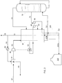
FIG. 2 is a process flow diagram of an embodiment of the present invention. - Referring to
FIG. 2 ,pressurized residue stream 10, which contains nitrogen, oxygen, argon, and carbon dioxide and is preferably at a pressure of at least 15 bara, is sent to front-end purification unit 30 to remove components such as carbon dioxide that would freeze at cryogenic temperatures (e.g., below -40°C).Purified stream 32 is then compressed infirst compressor 40 to a pressure of about 20 bara in this example to formpressurized stream 42 before being cooled inmain heat exchanger 50. - A cold box contains
main heat exchanger 50 andcolumn 70. -
Pressurized stream 42 is split intofirst portion 52 andsecond portion 54. In the embodiment shown, the split occurs withinmain heat exchanger 50; however, the split can also occurupstream heat exchanger 50.First portion 52 is further cooled and expanded across a Joule-Thomson valve before being introduced intodistillation column system 70, which in the embodiment shown comprises a nitrogen column (e.g., a single column with top condenser-reboiler). Those of ordinary skill in the art will readily understand that any system that is suitable for separating nitrogen from oxygen and argon can be used, for example, double or triple columns or column setups conducive for producing argon. - In the embodiment shown,
distillation column system 70 is preferably configured to producewaste gas 72 and nitrogen enrichedstream 74. Bottom liquid from the column is vaporised in the top condenser to produce waste gas and thewaste gas 72 is sent tomain heat exchanger 50 for warming. - In the embodiment shown, nitrogen enriched
stream 74 is preferably further compressed insecond compressor 90 before the compressed nitrogen stream is liquefied inmain heat exchanger 50 and then subcooled insubcooler 100. After subcooling, theliquid nitrogen 102 is preferably split intofirst portion 102a andsecond portion 102b, withfirst portion 102a being introduced intostorage tank 110 as product, andsecond portion 102b being expanded in order to provide refrigeration forsubcooler 100 andmain heat exchanger 50. - Power for the first and second compressors is provided for by expanding
second portion 54 of thepressurized stream 42 in the first andsecond turbines second portion 54 is removed from theheat exchanger 50 at a first intermediate temperature. After expansion, thesecond portion 54 is at a second intermediate temperature of the heat echanger. Thesecond portion 54 is expanded insecond turbine 80 to form expandedsecond portion 82 which is sent to the heat exchanger at a third intermediaite temperature colder than the first and second intermediate temperatures. The expandedsecond portion 82 is warmed in themain heat exchanger 50. In the embodiment shown, the expandedsecond portion 82, thesecond portion 102b, and thewaste gas 72 are combined within main heat exchanger to form combinedwaste stream 51; however, this is not required. - In a preferred embodiment, a
first portion 55 of combinedwaste stream 51 is warmed inheater 84 and then used to regenerate front-end purification system 30, with theregeneration gas 34, which now contains the desorbed carbon dioxide, being sent back, along with second portion of combinedwaste stream 53, to the flue gas vent stack. - A simulation was run using the embodiment shown in
FIG. 2 . 456 metric tonnes/h ofpressurized residue stream 10 containing 93.7% nitrogen, 3.3% oxygen, 1.1% argon, and 1.9% CO2 and at 15 bara was compressed to 20 bara infirst compressor 40. Approximately 246 metric tonnes/h (approximately 54% of stream 10) of flow were sent to thedistillation column system 70, with the remainder being expanded in the plurality ofturbines - Consequently, preferred embodiments of the current invention allow a user to utilize the pressurized residue stream of a cold membrane separator to produce large amounts of liquid nitrogen with essentially zero compression energy costs.
Claims (16)
- A process for producing liquid nitrogen, the process comprising the steps of:• providing a residual gas stream (10), wherein the residual gas stream is sourced from a retentate stream of a cold membrane, wherein the residual gas stream comprises nitrogen, argon, oxygen, and carbon dioxide;• purifying the residual gas stream in a front-end purification unit (30) to remove carbon dioxide, thereby forming a purified residual gas stream;• compressing the purified residual gas stream in a first compressor (40) to form a pressurized residual gas stream;• introducing the pressurized residual gas stream to a cold box, wherein a first portion (52) of the pressurized residual gas stream is cooled in a main heat exchanger (50), expanded within the cold box, and then fed to a distillation column system (70) for separation therein, thereby forming a nitrogen stream (74) and a waste stream (72);• withdrawing the waste stream from the distillation column system and warming said waste stream; and• withdrawing the nitrogen enriched stream from the distillation column and compressing the nitrogen stream in a second compressor (90) before liquefying the nitrogen stream within the cold box to produce a liquid nitrogen stream (102), wherein a second portion (54) of the pressurized residual gas stream is partially cooled in the main heat exchanger and then expanded in first and second turbines (60,80), having each an inlet temperature which is an intermediate temperature of the main heat exchanger, the turbines being configured to provide sufficient cooling energy to liquefy the nitrogen stream.
- The process of claim 1, wherein the residual gas stream (10) is derived from a flue gas stream from a power plant.
- The process of claim 1, wherein the first and second turbines (60,80) operate in series and at different temperatures.
- The process of claim 3, wherein the first turbine (60) has a warmer inlet temperature as compared to the second turbine (80), wherein the first turbine is configured to drive the first compressor (40), wherein the second turbine is configured to drive the second compressor (90).
- The process of claim 4, wherein the purified residual gas stream and the nitrogen enriched stream are compressed without the use of any externally-powered compressors.
- The process of claim 1, wherein the second compressor (90) is a compressor operating with an inlet temperature less than -100°C, possibly less than-130°C.
- The process of claim 1, wherein the first portion (52) of the pressurized residual gas stream is expanded across a Joule-Thomson valve prior to being fed to the distillation column system (70).
- The process of claim 1, wherein the liquid nitrogen stream (102) is subcooled in a subcooler (100) before at least part of the liquid nitrogen is stored in a liquid nitrogen tank.
- The process of claim 7, wherein a first portion (102a) of the subcooled nitrogen is stored in a liquid nitrogen tank (110) and a second portion (102b) of the subcooled nitrogen is expanded across a second Joule-Thomson valve and heated in the subcooler (100) and the main heat exchanger (50).
- The process of claim 1, further comprising the step of warming the second portion (82) of the pressurized residual gas stream, after expansion in the first and second turbines (60, 80), in the main heat exchanger (50).
- The process of claim 1, further comprising regenerating the front-end purification unit (30) using a stream selected from the group consisting of the expanded second portion of the pressurized residual gas stream (82), the waste stream (72), the second portion of the subcooled nitrogen (102b), and combinations thereof.
- The process of claim 1, wherein the residual gas stream (10) is at a pressure above 13 bara.
- The process of claim 1, wherein the liquid nitrogen (102) is produced with only refrigeration provided by the expansion of streams derived from the residual gas stream (10).
- An apparatus for producing liquid nitrogen, the apparatus comprising:• means for providing a residual gas stream (10), wherein the residual gas stream is sourced from a retentate stream of a cold membrane used to separate carbon dioxide from a flue gas stream sourced from a combustion zone of a power plant, wherein the residual gas stream comprises nitrogen, argon, oxygen, and carbon dioxide;• a front-end purification unit (30) for purifying the residual gas stream to remove carbon dioxide, thereby forming a purified residual gas stream (32);• a first compressor (40) for compressing the purified residual gas stream to form a pressurized residual gas stream (42);• a distillation column system (70)• a main heat exchanger (50) for cooling a first portion (52) of the purified residual gas stream and a Joule-Thomson valve for expanding the first portion before introducing the first portion to a distillation column of the distillation column system configured to produce a nitrogen enriched fluid (74) and a waste stream (72);• means for sending a second portion (54) of the purified residual gas stream to be cooled in the main heat exchanger and• a first turbine (60) and a second turbine (80) in both of which the second portion is expanded to form an expanded second portion;• means for sending the expanded second portion (82) to be warmed in the main heat exchanger against the first portion and the second portion;• a second compressor (90) for compressing the nitrogen enriched fluid and means for cooling the nitrogen enriched fluid to form liquid nitrogen (102);• a storage tank (110) for storing a first portion (102a) of the liquid nitrogen ; and• a second Joule-Thomson valve for expanding a second portion (102b) of the liquid nitrogen and means for sending the expanded second portion of the liquid nitrogen to be warmed in the main heat exchanger.
- The apparatus of claim 14, further comprising means for sending a regeneration gas to the front-end purification unit (30) which is a warm stream that has been warmed in the main heat exchanger and that is selected from the group consisting of the expanded second portion (82) of the pressurized residual gas stream, the waste stream (72), the second portion of the liquid nitrogen (102b), and combinations thereof.
- The apparatus of claim 14, wherein the first and second turbines (60, 80) are coupled to the first and second compressors (40, 90) respectively.
Applications Claiming Priority (1)
| Application Number | Priority Date | Filing Date | Title |
|---|---|---|---|
| US16/697,593 US11566841B2 (en) | 2019-11-27 | 2019-11-27 | Cryogenic liquefier by integration with power plant |
Publications (2)
| Publication Number | Publication Date |
|---|---|
| EP3828487A1 true EP3828487A1 (en) | 2021-06-02 |
| EP3828487B1 EP3828487B1 (en) | 2025-07-23 |
Family
ID=73642569
Family Applications (1)
| Application Number | Title | Priority Date | Filing Date |
|---|---|---|---|
| EP20210161.4A Active EP3828487B1 (en) | 2019-11-27 | 2020-11-27 | Process and apparatus for the production of liquid nitrogen |
Country Status (2)
| Country | Link |
|---|---|
| US (1) | US11566841B2 (en) |
| EP (1) | EP3828487B1 (en) |
Families Citing this family (1)
| Publication number | Priority date | Publication date | Assignee | Title |
|---|---|---|---|---|
| FR3122918B1 (en) * | 2021-05-12 | 2023-06-09 | Air Liquide | Method and apparatus for liquefying a gas rich in carbon dioxide |
Citations (7)
| Publication number | Priority date | Publication date | Assignee | Title |
|---|---|---|---|---|
| GB1331458A (en) * | 1970-12-22 | 1973-09-26 | Petrocarbon Dev Ltd | Single column liquid nitrogen plant |
| US4705548A (en) * | 1986-04-25 | 1987-11-10 | Air Products And Chemicals, Inc. | Liquid products using an air and a nitrogen recycle liquefier |
| DE102006036750A1 (en) * | 2006-08-05 | 2008-02-07 | Messer Group Gmbh | Process and apparatus for the pretreatment of fuels |
| US20080176174A1 (en) * | 2007-01-23 | 2008-07-24 | Vincent White | Purification of carbon dioxide |
| DE102008062497A1 (en) * | 2008-12-16 | 2010-06-17 | Linde-Kca-Dresden Gmbh | Process and apparatus for treating a carbon dioxide-containing gas stream from a large combustion plant |
| DE102013019504A1 (en) * | 2013-11-21 | 2015-05-21 | Linde Aktiengesellschaft | Process for recovering a liquid nitrogen product by cryogenic separation of air and air separation plant |
| US20180347900A1 (en) * | 2017-06-02 | 2018-12-06 | Linde Aktiengesellschaft | Process for obtaining one or more air products and air separation plant |
Family Cites Families (14)
| Publication number | Priority date | Publication date | Assignee | Title |
|---|---|---|---|---|
| DE19529681C2 (en) * | 1995-08-11 | 1997-05-28 | Linde Ag | Method and device for air separation by low-temperature rectification |
| US5724805A (en) | 1995-08-21 | 1998-03-10 | University Of Massachusetts-Lowell | Power plant with carbon dioxide capture and zero pollutant emissions |
| US5704229A (en) * | 1996-12-18 | 1998-01-06 | The Boc Group, Inc. | Process and apparatus for producing nitrogen |
| US20100018218A1 (en) | 2008-07-25 | 2010-01-28 | Riley Horace E | Power plant with emissions recovery |
| US8501125B2 (en) | 2008-10-08 | 2013-08-06 | Expansion Energy, Llc | System and method of carbon capture and sequestration, environmental remediation, and metals recovery |
| FR2955926B1 (en) * | 2010-02-04 | 2012-03-02 | Air Liquide | METHOD AND APPARATUS FOR AIR SEPARATION BY CRYOGENIC DISTILLATION |
| FR2990500A1 (en) * | 2012-05-11 | 2013-11-15 | Air Liquide | METHOD AND APPARATUS FOR AIR SEPARATION BY CRYOGENIC DISTILLATION |
| JP6087196B2 (en) * | 2012-12-28 | 2017-03-01 | レール・リキード−ソシエテ・アノニム・プール・レテュード・エ・レクスプロワタシオン・デ・プロセデ・ジョルジュ・クロード | Low temperature compressed gas or liquefied gas manufacturing apparatus and manufacturing method |
| US20150168058A1 (en) * | 2013-12-17 | 2015-06-18 | L'air Liquide, Societe Anonyme Pour I'etude Et I'exploitation Des Procedes Georges Claude | Apparatus for producing liquid nitrogen |
| US20170038135A1 (en) * | 2015-08-06 | 2017-02-09 | L'air Liquide, Societe Anonyme Pour L'etude Et L'exploitation Des Procedes Georges Claude | Method for the production of liquefied natural gas and liquid nitrogen |
| US20180313603A1 (en) * | 2015-10-28 | 2018-11-01 | L'Air Liquide, Société Anonyme pour I'Etude et I'Exploitation des Procédés Georges Claude | Apparatus and method for producing liquefied gas |
| US20170176098A1 (en) * | 2015-12-22 | 2017-06-22 | L'air Liquide, Societe Anonyme Pour L'etude Et L'exploitation Des Procedes Georges Claude | Systems and methods for automated startup of an air separation plant |
| US11117092B2 (en) * | 2018-03-14 | 2021-09-14 | Gas Technology Institute | Energy efficient membrane-based process for CO2 capture |
| JP6351895B1 (en) * | 2018-03-20 | 2018-07-04 | レール・リキード−ソシエテ・アノニム・プール・レテュード・エ・レクスプロワタシオン・デ・プロセデ・ジョルジュ・クロード | Nitrogen production method and nitrogen production apparatus |
-
2019
- 2019-11-27 US US16/697,593 patent/US11566841B2/en active Active
-
2020
- 2020-11-27 EP EP20210161.4A patent/EP3828487B1/en active Active
Patent Citations (7)
| Publication number | Priority date | Publication date | Assignee | Title |
|---|---|---|---|---|
| GB1331458A (en) * | 1970-12-22 | 1973-09-26 | Petrocarbon Dev Ltd | Single column liquid nitrogen plant |
| US4705548A (en) * | 1986-04-25 | 1987-11-10 | Air Products And Chemicals, Inc. | Liquid products using an air and a nitrogen recycle liquefier |
| DE102006036750A1 (en) * | 2006-08-05 | 2008-02-07 | Messer Group Gmbh | Process and apparatus for the pretreatment of fuels |
| US20080176174A1 (en) * | 2007-01-23 | 2008-07-24 | Vincent White | Purification of carbon dioxide |
| DE102008062497A1 (en) * | 2008-12-16 | 2010-06-17 | Linde-Kca-Dresden Gmbh | Process and apparatus for treating a carbon dioxide-containing gas stream from a large combustion plant |
| DE102013019504A1 (en) * | 2013-11-21 | 2015-05-21 | Linde Aktiengesellschaft | Process for recovering a liquid nitrogen product by cryogenic separation of air and air separation plant |
| US20180347900A1 (en) * | 2017-06-02 | 2018-12-06 | Linde Aktiengesellschaft | Process for obtaining one or more air products and air separation plant |
Also Published As
| Publication number | Publication date |
|---|---|
| US20210156303A1 (en) | 2021-05-27 |
| EP3828487B1 (en) | 2025-07-23 |
| US11566841B2 (en) | 2023-01-31 |
Similar Documents
| Publication | Publication Date | Title |
|---|---|---|
| CN109690215B (en) | Integration of industrial gas sites with liquid hydrogen production | |
| US9810103B2 (en) | Method and device for generating electrical energy | |
| US10288346B2 (en) | Method for liquefaction of industrial gas by integration of methanol plant and air separation unit | |
| DK3129613T3 (en) | Process and plant for energy storage and recovery | |
| JP4728219B2 (en) | Method and system for producing pressurized air gas by cryogenic distillation of air | |
| CA2550947A1 (en) | Cryogenic air separation process and apparatus | |
| US7228714B2 (en) | Natural gas liquefaction system | |
| KR102488158B1 (en) | Lng production with nitrogen removal | |
| EP2634517B1 (en) | Process and apparatus for the separation of air by cryogenic distillation | |
| US10281203B2 (en) | Method for liquefaction of industrial gas by integration of methanol plant and air separation unit | |
| JP4276520B2 (en) | Operation method of air separation device | |
| JP5932127B2 (en) | Carbon dioxide liquefaction equipment | |
| EP3828487B1 (en) | Process and apparatus for the production of liquid nitrogen | |
| US10612842B2 (en) | LNG integration with cryogenic unit | |
| US11913718B2 (en) | Argon and power production by integration with power plant | |
| EP1726900A1 (en) | Process and apparatus for the separation of air by cryogenic distillation | |
| EP3271671B1 (en) | Plant for the liquefaction of nitrogen using the recovery of cold energy deriving from the evaporation of liquefied natural gas | |
| US20250198695A1 (en) | Method for liquefying a methane-rich feed gas, and corresponding facility | |
| TW201615255A (en) | Method and apparatus for obtaining a compressed gas product by cryogenic separation of air | |
| US20240353174A1 (en) | Dual temperature liquid oxygen subcooling in an air separation unit | |
| JPS6338632B2 (en) | ||
| JP2631809B2 (en) | Carbon dioxide recovery and liquefaction equipment from industrial exhaust gas | |
| JP2005090915A (en) | Air separator and air separating method | |
| Brennan et al. | Liquefaction and Separation of Gases | |
| EA037510B1 (en) | Method for producing liquid helium |
Legal Events
| Date | Code | Title | Description |
|---|---|---|---|
| PUAI | Public reference made under article 153(3) epc to a published international application that has entered the european phase |
Free format text: ORIGINAL CODE: 0009012 |
|
| STAA | Information on the status of an ep patent application or granted ep patent |
Free format text: STATUS: THE APPLICATION HAS BEEN PUBLISHED |
|
| AK | Designated contracting states |
Kind code of ref document: A1 Designated state(s): AL AT BE BG CH CY CZ DE DK EE ES FI FR GB GR HR HU IE IS IT LI LT LU LV MC MK MT NL NO PL PT RO RS SE SI SK SM TR |
|
| STAA | Information on the status of an ep patent application or granted ep patent |
Free format text: STATUS: REQUEST FOR EXAMINATION WAS MADE |
|
| 17P | Request for examination filed |
Effective date: 20211202 |
|
| RBV | Designated contracting states (corrected) |
Designated state(s): AL AT BE BG CH CY CZ DE DK EE ES FI FR GB GR HR HU IE IS IT LI LT LU LV MC MK MT NL NO PL PT RO RS SE SI SK SM TR |
|
| RAP3 | Party data changed (applicant data changed or rights of an application transferred) |
Owner name: L'AIR LIQUIDE, SOCIETE ANONYME POUR L'ETUDE ET L'EXPLOITATION DES PROCEDES GEORGES CLAUDE |
|
| GRAP | Despatch of communication of intention to grant a patent |
Free format text: ORIGINAL CODE: EPIDOSNIGR1 |
|
| STAA | Information on the status of an ep patent application or granted ep patent |
Free format text: STATUS: GRANT OF PATENT IS INTENDED |
|
| INTG | Intention to grant announced |
Effective date: 20250513 |
|
| GRAS | Grant fee paid |
Free format text: ORIGINAL CODE: EPIDOSNIGR3 |
|
| GRAA | (expected) grant |
Free format text: ORIGINAL CODE: 0009210 |
|
| STAA | Information on the status of an ep patent application or granted ep patent |
Free format text: STATUS: THE PATENT HAS BEEN GRANTED |
|
| AK | Designated contracting states |
Kind code of ref document: B1 Designated state(s): AL AT BE BG CH CY CZ DE DK EE ES FI FR GB GR HR HU IE IS IT LI LT LU LV MC MK MT NL NO PL PT RO RS SE SI SK SM TR |
|
| REG | Reference to a national code |
Ref country code: GB Ref legal event code: FG4D |
|
| REG | Reference to a national code |
Ref country code: CH Ref legal event code: EP |
|
| REG | Reference to a national code |
Ref country code: IE Ref legal event code: FG4D |
|
| REG | Reference to a national code |
Ref country code: DE Ref legal event code: R096 Ref document number: 602020054932 Country of ref document: DE |
|
| REG | Reference to a national code |
Ref country code: NL Ref legal event code: MP Effective date: 20250723 |
|
| PG25 | Lapsed in a contracting state [announced via postgrant information from national office to epo] |
Ref country code: PT Free format text: LAPSE BECAUSE OF FAILURE TO SUBMIT A TRANSLATION OF THE DESCRIPTION OR TO PAY THE FEE WITHIN THE PRESCRIBED TIME-LIMIT Effective date: 20251124 |
|
| PG25 | Lapsed in a contracting state [announced via postgrant information from national office to epo] |
Ref country code: NL Free format text: LAPSE BECAUSE OF FAILURE TO SUBMIT A TRANSLATION OF THE DESCRIPTION OR TO PAY THE FEE WITHIN THE PRESCRIBED TIME-LIMIT Effective date: 20250723 |
|
| REG | Reference to a national code |
Ref country code: AT Ref legal event code: MK05 Ref document number: 1816794 Country of ref document: AT Kind code of ref document: T Effective date: 20250723 |
|
| PG25 | Lapsed in a contracting state [announced via postgrant information from national office to epo] |
Ref country code: IS Free format text: LAPSE BECAUSE OF FAILURE TO SUBMIT A TRANSLATION OF THE DESCRIPTION OR TO PAY THE FEE WITHIN THE PRESCRIBED TIME-LIMIT Effective date: 20251123 |
|
| PGFP | Annual fee paid to national office [announced via postgrant information from national office to epo] |
Ref country code: DE Payment date: 20251119 Year of fee payment: 6 |
|
| PG25 | Lapsed in a contracting state [announced via postgrant information from national office to epo] |
Ref country code: NO Free format text: LAPSE BECAUSE OF FAILURE TO SUBMIT A TRANSLATION OF THE DESCRIPTION OR TO PAY THE FEE WITHIN THE PRESCRIBED TIME-LIMIT Effective date: 20251023 |
|
| REG | Reference to a national code |
Ref country code: LT Ref legal event code: MG9D |
|
| PG25 | Lapsed in a contracting state [announced via postgrant information from national office to epo] |
Ref country code: AT Free format text: LAPSE BECAUSE OF FAILURE TO SUBMIT A TRANSLATION OF THE DESCRIPTION OR TO PAY THE FEE WITHIN THE PRESCRIBED TIME-LIMIT Effective date: 20250723 |
|
| PG25 | Lapsed in a contracting state [announced via postgrant information from national office to epo] |
Ref country code: FI Free format text: LAPSE BECAUSE OF FAILURE TO SUBMIT A TRANSLATION OF THE DESCRIPTION OR TO PAY THE FEE WITHIN THE PRESCRIBED TIME-LIMIT Effective date: 20250723 |
|
| PG25 | Lapsed in a contracting state [announced via postgrant information from national office to epo] |
Ref country code: HR Free format text: LAPSE BECAUSE OF FAILURE TO SUBMIT A TRANSLATION OF THE DESCRIPTION OR TO PAY THE FEE WITHIN THE PRESCRIBED TIME-LIMIT Effective date: 20250723 |
|
| PGFP | Annual fee paid to national office [announced via postgrant information from national office to epo] |
Ref country code: FR Payment date: 20251126 Year of fee payment: 6 |
|
| PG25 | Lapsed in a contracting state [announced via postgrant information from national office to epo] |
Ref country code: GR Free format text: LAPSE BECAUSE OF FAILURE TO SUBMIT A TRANSLATION OF THE DESCRIPTION OR TO PAY THE FEE WITHIN THE PRESCRIBED TIME-LIMIT Effective date: 20251024 |
|
| PG25 | Lapsed in a contracting state [announced via postgrant information from national office to epo] |
Ref country code: SE Free format text: LAPSE BECAUSE OF FAILURE TO SUBMIT A TRANSLATION OF THE DESCRIPTION OR TO PAY THE FEE WITHIN THE PRESCRIBED TIME-LIMIT Effective date: 20250723 |
|
| PG25 | Lapsed in a contracting state [announced via postgrant information from national office to epo] |
Ref country code: LV Free format text: LAPSE BECAUSE OF FAILURE TO SUBMIT A TRANSLATION OF THE DESCRIPTION OR TO PAY THE FEE WITHIN THE PRESCRIBED TIME-LIMIT Effective date: 20250723 |
|
| PG25 | Lapsed in a contracting state [announced via postgrant information from national office to epo] |
Ref country code: BG Free format text: LAPSE BECAUSE OF FAILURE TO SUBMIT A TRANSLATION OF THE DESCRIPTION OR TO PAY THE FEE WITHIN THE PRESCRIBED TIME-LIMIT Effective date: 20250723 Ref country code: PL Free format text: LAPSE BECAUSE OF FAILURE TO SUBMIT A TRANSLATION OF THE DESCRIPTION OR TO PAY THE FEE WITHIN THE PRESCRIBED TIME-LIMIT Effective date: 20250723 |
|
| PG25 | Lapsed in a contracting state [announced via postgrant information from national office to epo] |
Ref country code: RS Free format text: LAPSE BECAUSE OF FAILURE TO SUBMIT A TRANSLATION OF THE DESCRIPTION OR TO PAY THE FEE WITHIN THE PRESCRIBED TIME-LIMIT Effective date: 20251023 |
|
| PG25 | Lapsed in a contracting state [announced via postgrant information from national office to epo] |
Ref country code: ES Free format text: LAPSE BECAUSE OF FAILURE TO SUBMIT A TRANSLATION OF THE DESCRIPTION OR TO PAY THE FEE WITHIN THE PRESCRIBED TIME-LIMIT Effective date: 20250723 |
|
| PG25 | Lapsed in a contracting state [announced via postgrant information from national office to epo] |
Ref country code: RO Free format text: LAPSE BECAUSE OF FAILURE TO SUBMIT A TRANSLATION OF THE DESCRIPTION OR TO PAY THE FEE WITHIN THE PRESCRIBED TIME-LIMIT Effective date: 20250723 |
|
| PG25 | Lapsed in a contracting state [announced via postgrant information from national office to epo] |
Ref country code: SM Free format text: LAPSE BECAUSE OF FAILURE TO SUBMIT A TRANSLATION OF THE DESCRIPTION OR TO PAY THE FEE WITHIN THE PRESCRIBED TIME-LIMIT Effective date: 20250723 |
|
| PG25 | Lapsed in a contracting state [announced via postgrant information from national office to epo] |
Ref country code: DK Free format text: LAPSE BECAUSE OF FAILURE TO SUBMIT A TRANSLATION OF THE DESCRIPTION OR TO PAY THE FEE WITHIN THE PRESCRIBED TIME-LIMIT Effective date: 20250723 |
|
| PG25 | Lapsed in a contracting state [announced via postgrant information from national office to epo] |
Ref country code: IT Free format text: LAPSE BECAUSE OF FAILURE TO SUBMIT A TRANSLATION OF THE DESCRIPTION OR TO PAY THE FEE WITHIN THE PRESCRIBED TIME-LIMIT Effective date: 20250723 |
|
| PG25 | Lapsed in a contracting state [announced via postgrant information from national office to epo] |
Ref country code: CZ Free format text: LAPSE BECAUSE OF FAILURE TO SUBMIT A TRANSLATION OF THE DESCRIPTION OR TO PAY THE FEE WITHIN THE PRESCRIBED TIME-LIMIT Effective date: 20250723 |
|
| PG25 | Lapsed in a contracting state [announced via postgrant information from national office to epo] |
Ref country code: SK Free format text: LAPSE BECAUSE OF FAILURE TO SUBMIT A TRANSLATION OF THE DESCRIPTION OR TO PAY THE FEE WITHIN THE PRESCRIBED TIME-LIMIT Effective date: 20250723 Ref country code: EE Free format text: LAPSE BECAUSE OF FAILURE TO SUBMIT A TRANSLATION OF THE DESCRIPTION OR TO PAY THE FEE WITHIN THE PRESCRIBED TIME-LIMIT Effective date: 20250723 |