EP3828120A1 - Kran und steuersystem für einen kran - Google Patents
Kran und steuersystem für einen kran Download PDFInfo
- Publication number
- EP3828120A1 EP3828120A1 EP19839926.3A EP19839926A EP3828120A1 EP 3828120 A1 EP3828120 A1 EP 3828120A1 EP 19839926 A EP19839926 A EP 19839926A EP 3828120 A1 EP3828120 A1 EP 3828120A1
- Authority
- EP
- European Patent Office
- Prior art keywords
- load
- crane
- target
- boom
- signal
- Prior art date
- Legal status (The legal status is an assumption and is not a legal conclusion. Google has not performed a legal analysis and makes no representation as to the accuracy of the status listed.)
- Granted
Links
- 230000010354 integration Effects 0.000 claims abstract description 6
- 238000001514 detection method Methods 0.000 claims description 21
- 230000001133 acceleration Effects 0.000 claims description 10
- 230000004069 differentiation Effects 0.000 claims description 5
- 230000006870 function Effects 0.000 abstract description 32
- 238000000034 method Methods 0.000 description 21
- 230000008569 process Effects 0.000 description 18
- 230000007274 generation of a signal involved in cell-cell signaling Effects 0.000 description 11
- 238000010586 diagram Methods 0.000 description 5
- 238000004804 winding Methods 0.000 description 4
- 230000008859 change Effects 0.000 description 2
- 238000000354 decomposition reaction Methods 0.000 description 2
- 230000000694 effects Effects 0.000 description 2
- 238000013178 mathematical model Methods 0.000 description 2
- 238000012544 monitoring process Methods 0.000 description 2
- 230000001144 postural effect Effects 0.000 description 2
- 238000013528 artificial neural network Methods 0.000 description 1
- 239000004973 liquid crystal related substance Substances 0.000 description 1
- 238000012986 modification Methods 0.000 description 1
- 230000004048 modification Effects 0.000 description 1
- 239000002356 single layer Substances 0.000 description 1
- 238000011144 upstream manufacturing Methods 0.000 description 1
Images


Classifications
-
- B—PERFORMING OPERATIONS; TRANSPORTING
- B66—HOISTING; LIFTING; HAULING
- B66C—CRANES; LOAD-ENGAGING ELEMENTS OR DEVICES FOR CRANES, CAPSTANS, WINCHES, OR TACKLES
- B66C23/00—Cranes comprising essentially a beam, boom, or triangular structure acting as a cantilever and mounted for translatory of swinging movements in vertical or horizontal planes or a combination of such movements, e.g. jib-cranes, derricks, tower cranes
- B66C23/18—Cranes comprising essentially a beam, boom, or triangular structure acting as a cantilever and mounted for translatory of swinging movements in vertical or horizontal planes or a combination of such movements, e.g. jib-cranes, derricks, tower cranes specially adapted for use in particular purposes
- B66C23/36—Cranes comprising essentially a beam, boom, or triangular structure acting as a cantilever and mounted for translatory of swinging movements in vertical or horizontal planes or a combination of such movements, e.g. jib-cranes, derricks, tower cranes specially adapted for use in particular purposes mounted on road or rail vehicles; Manually-movable jib-cranes for use in workshops; Floating cranes
- B66C23/42—Cranes comprising essentially a beam, boom, or triangular structure acting as a cantilever and mounted for translatory of swinging movements in vertical or horizontal planes or a combination of such movements, e.g. jib-cranes, derricks, tower cranes specially adapted for use in particular purposes mounted on road or rail vehicles; Manually-movable jib-cranes for use in workshops; Floating cranes with jibs of adjustable configuration, e.g. foldable
-
- B—PERFORMING OPERATIONS; TRANSPORTING
- B66—HOISTING; LIFTING; HAULING
- B66C—CRANES; LOAD-ENGAGING ELEMENTS OR DEVICES FOR CRANES, CAPSTANS, WINCHES, OR TACKLES
- B66C13/00—Other constructional features or details
- B66C13/18—Control systems or devices
- B66C13/22—Control systems or devices for electric drives
-
- B—PERFORMING OPERATIONS; TRANSPORTING
- B66—HOISTING; LIFTING; HAULING
- B66C—CRANES; LOAD-ENGAGING ELEMENTS OR DEVICES FOR CRANES, CAPSTANS, WINCHES, OR TACKLES
- B66C13/00—Other constructional features or details
- B66C13/04—Auxiliary devices for controlling movements of suspended loads, or preventing cable slack
- B66C13/06—Auxiliary devices for controlling movements of suspended loads, or preventing cable slack for minimising or preventing longitudinal or transverse swinging of loads
- B66C13/063—Auxiliary devices for controlling movements of suspended loads, or preventing cable slack for minimising or preventing longitudinal or transverse swinging of loads electrical
-
- B—PERFORMING OPERATIONS; TRANSPORTING
- B66—HOISTING; LIFTING; HAULING
- B66C—CRANES; LOAD-ENGAGING ELEMENTS OR DEVICES FOR CRANES, CAPSTANS, WINCHES, OR TACKLES
- B66C13/00—Other constructional features or details
- B66C13/18—Control systems or devices
- B66C13/46—Position indicators for suspended loads or for crane elements
-
- B—PERFORMING OPERATIONS; TRANSPORTING
- B66—HOISTING; LIFTING; HAULING
- B66C—CRANES; LOAD-ENGAGING ELEMENTS OR DEVICES FOR CRANES, CAPSTANS, WINCHES, OR TACKLES
- B66C13/00—Other constructional features or details
- B66C13/18—Control systems or devices
- B66C13/48—Automatic control of crane drives for producing a single or repeated working cycle; Programme control
-
- B—PERFORMING OPERATIONS; TRANSPORTING
- B66—HOISTING; LIFTING; HAULING
- B66C—CRANES; LOAD-ENGAGING ELEMENTS OR DEVICES FOR CRANES, CAPSTANS, WINCHES, OR TACKLES
- B66C23/00—Cranes comprising essentially a beam, boom, or triangular structure acting as a cantilever and mounted for translatory of swinging movements in vertical or horizontal planes or a combination of such movements, e.g. jib-cranes, derricks, tower cranes
- B66C23/88—Safety gear
-
- B—PERFORMING OPERATIONS; TRANSPORTING
- B66—HOISTING; LIFTING; HAULING
- B66C—CRANES; LOAD-ENGAGING ELEMENTS OR DEVICES FOR CRANES, CAPSTANS, WINCHES, OR TACKLES
- B66C2700/00—Cranes
- B66C2700/03—Cranes with arms or jibs; Multiple cranes
- B66C2700/0321—Travelling cranes
- B66C2700/0357—Cranes on road or off-road vehicles, on trailers or towed vehicles; Cranes on wheels or crane-trucks
- B66C2700/0364—Cranes on road or off-road vehicles, on trailers or towed vehicles; Cranes on wheels or crane-trucks with a slewing arm
-
- B—PERFORMING OPERATIONS; TRANSPORTING
- B66—HOISTING; LIFTING; HAULING
- B66C—CRANES; LOAD-ENGAGING ELEMENTS OR DEVICES FOR CRANES, CAPSTANS, WINCHES, OR TACKLES
- B66C2700/00—Cranes
- B66C2700/08—Electrical assemblies or electrical control devices for cranes, winches, capstans or electrical hoists
Definitions
- the present invention relates to a crane and a control system for the crane.
- a speed signal relating to a manipulation speed of a manipulation tool and a direction signal relating to a manipulation direction of the manipulation tool are transmitted from the manipulation terminal to the crane. Therefore, in the crane, at a start or stop of movement at which a speed signal from the manipulation terminal is input in the form of a step function, discontinuous acceleration sometimes occurs, causing swinging of the load.
- the crane described in PTL 2 is controlled based on a mathematical model determined in advance such that swinging of a load is minimized by enhancement in positioning accuracy of the crane. Therefore, if the mathematical model has a large error, an error in future predictive value also becomes large, which causes the disadvantages of a decrease in positioning accuracy of the crane and an increase of swinging of the load.
- An object of the present invention is to provide a crane and a control system for the crane that enable, when an actuator is controlled with reference to a load, moving the load in a manner intended by an operator while curbing swinging of the load, by learning a dynamic characteristic of the crane.
- the present invention provides a crane in which an actuator is controlled based on a target speed signal relating to a moving direction and a speed of a load suspended from a boom by a wire rope, the crane including: a manipulation tool with which an acceleration time, the speed and the moving direction of the load for the target speed signal are input; a swivel angle detection section for the boom; a luffing angle detection section for the boom; an extension/retraction length detection section for the boom; a load position detection section that detects a current position of the load relative to a reference position; and a control apparatus including a feedback control section that computes a target course signal for the load from the target speed signal by integration and corrects the target course signal based on a difference of the current position of the load from the target course signal, and a feedforward control section that adjusts a weight coefficient of a transfer function representing a characteristic of the crane based on the corrected target course signal, in which the control apparatus preferably obtains the current position of the load relative to the reference position from the load position
- the control apparatus includes a plurality of the feedforward control sections; and the transfer function is decomposed into one or more first-order models, the weight coefficient is provided for each of the one or more models, and the weight coefficient that is adjusted is assigned for each of the feedforward control sections.
- the present invention provides a control system for a crane in which an actuator is controlled based on a target speed signal relating to a moving direction and a speed of a load
- the control system including: a feedback control section that computes a target course signal for the load from the target speed signal by integration, corrects the target course signal based on a difference of a current position of the load from the target course signal for the load, and computes a target position of the load from the corrected target course signal; and a feedforward control section that adjusts a weight coefficient of a transfer function representing a characteristic of the crane based on the corrected target course signal and corrects the corrected target course signal using the transfer function with the weight coefficient adjusted, in which each time the target course signal is corrected by the feedback control section, the weight coefficient of the transfer function is adjusted by the feedforward control section.
- control system for a crane according to the present invention: the control system includes a plurality of the feedforward control sections; and the transfer function is decomposed into one or more first-order models, the weight coefficient is provided for each of the one or more models, and the weight coefficient that is adjusted is assigned for each of the feedforward control sections.
- a high-order transfer function is adjusted for each first-order model, and thus, flexibly responds to a change in dynamic characteristic. Consequently, it is possible to, when the actuator is controlled with reference to a load, move the load in a manner intended by an operator while curbing swinging of the load, by learning a dynamic characteristic of the crane from movement of the load.
- the crane and the control system for the crane according to the present invention enable determining the coefficient of the low-pass filter according to a dynamic characteristic of the crane. Consequently, it is possible to, when the actuator is controlled with reference to a load, move the load in a manner intended by an operator while curbing swinging of the load, by learning a dynamic characteristic of the crane from movement of the load.
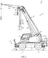
- crane 1 which is a mobile crane (rough terrain crane)
- FIGS. 1 and 2 the working vehicle may also be an all-terrain crane, a truck crane, a truck loader crane, an aerial work vehicle, or the like.
- crane 1 is a mobile crane capable of moving to an unspecified place.
- Crane 1 includes vehicle 2 and crane apparatus 6, which is a working apparatus, and manipulation terminal 32 with which crane apparatus 6 can be manipulated (see FIG. 2 ).
- Vehicle 2 is a travelling body that carries crane apparatus 6.
- Vehicle 2 includes a plurality of wheels 3 and travels using engine 4 as a power source.
- Vehicle 2 is provided with outriggers 5.
- Outriggers 5 are composed of projecting beams hydraulically extendable on opposite sides in a width direction of vehicle 2 and hydraulic jack cylinders extendable in a direction perpendicular to the ground.
- Vehicle 2 can expand a workable region of crane 1 by extending outriggers 5 in the width direction of vehicle 2 and bringing the jack cylinders into contact with the ground.
- Crane apparatus 6 is a working apparatus that hoists up load W with a wire rope.
- Crane apparatus 6 includes, for example, swivel base 7, boom 9, jib 9a, main hook block 10, sub hook block 11, hydraulic luffing cylinder 12, main winch 13, main wire rope 14, sub winch 15, sub wire rope 16 and cabin 17.
- Swivel base 7 is a drive apparatus configured to enable crane apparatus 6 to swivel.
- Swivel base 7 is disposed on a frame of vehicle 2 via an annular bearing.
- Swivel base 7 is configured to be rotatable with a center of the annular bearing as a rotational center.
- Swivel base 7 is provided with hydraulic swivel motor 8, which is an actuator.
- Swivel base 7 is configured to be capable of swiveling in one and other directions via hydraulic swivel motor 8.
- Each of swivel-base cameras 7b which form a load position detection section, is a monitoring apparatus that takes an image of, for example, obstacles and people around swivel base 7.
- Swivel-base cameras 7b are provided on opposite, left and right, sides of the front of swivel base 7 and opposite, left and right, sides of the rear of swivel base 7.
- the swivel-base cameras 7b take images of respective areas around places at which swivel-base cameras 7b are installed, to cover an entire area surrounding swivel base 7 as a monitoring area.
- swivel-base cameras 7b disposed on the opposite, left and right, sides of the front of swivel base 7 are configured to be usable as a stereo camera set.
- swivel-base cameras 7b at the front of swivel base 7 can be configured as a load position detection section that detects positional information of suspended load W, by being used as a stereo camera set.
- the load position detection section may be composed of later-described boom camera 9b.
- the load position detection section only needs to be one that is capable of detecting positional information of load W such as a millimeter-wave radar, an acceleration sensor, a GNSS apparatus, or the like.
- Hydraulic swivel motor 8 is an actuator that is manipulated to rotate via swivel valve 23 (see FIG. 2 ), which is an electromagnetic proportional switching valve. Swivel valve 23 can control a flow rate of an operating oil supplied to hydraulic swivel motor 8 to any flow rate.
- swivel base 7 is configured to be controllable to have any swivel speed via hydraulic swivel motor 8 manipulated to rotate via swivel valve 23.
- Swivel base 7 is provided with swivel sensor 27 (see FIG. 2 ) that detects swivel angle ⁇ z (angle) and swivel speed of swivel base 7.
- Boom 9 is a movable boom that supports a wire rope such that load W can be hoisted.
- Boom 9 is composed of a plurality of boom members.
- a base end of a base boom member is swingably provided at a substantial center of swivel base 7.
- Boom 9 is configured to be capable of being axially extended/retracted by moving the respective boom members with a non-illustrated hydraulic extension/retraction cylinder, which is an actuator.
- boom 9 is provided with jib 9a.
- the non-illustrated hydraulic extension/retraction cylinder is an actuator to be manipulated to extend and retract via extension/retraction valve 24 (see FIG. 2 ), which is electromagnetic proportional switching valve.
- Extension/retraction valve 24 can control a flow rate of an operating oil supplied to the hydraulic extension/retraction cylinder to any flow rate.
- Boom 9 is provided with extension/retraction sensor 28 that detects a length of boom 9 and azimuth sensor 29 that detects an azimuth with a tip of boom 9 as a center.
- Boom camera 9b (see FIG. 2 ) is a sensing apparatus that takes an image of load W and features around load W. Boom camera 9b is provided at a tip portion of boom 9. Boom camera 9b is configured to be capable of taking an image of load W, and features and geographical features around crane 1 from vertically above load W.
- Main hook block 10 and sub hook block 11 are suspending tools for suspending load W.
- Main hook block 10 is provided with a plurality of hook sheaves around which main wire rope 14 is wound and main hook 10a for suspending load W.
- Sub hook block 11 is provided with sub hook 11a for suspending load W.
- Hydraulic luffing cylinder 12 is an actuator that luffs up and down boom 9 and holds a posture of boom 9.
- Hydraulic luffing cylinder 12 is manipulated to extend or retract via luffing valve 25 (see FIG. 2 ), which is an electromagnetic proportional switching valve.
- Luffing valve 25 can control a flow rate of an operating oil supplied to hydraulic luffing cylinder 12 to any flow rate.
- Boom 9 is provided with luffing sensor 30 (see FIG. 2 ) that detects luffing angle ⁇ x.
- Main winch 13 and sub winch 15 are winding apparatuses that pull in (wind) or let out (unwind) main wire rope 14 and sub wire rope 16.
- Main winch 13 is configured such that a main drum around which main wire rope 14 is wound is rotated by a non-illustrated main hydraulic motor, which is an actuator
- sub winch 15 is configured such that a sub drum around which sub wire rope 16 is wound is rotated by a non-illustrated sub hydraulic motor, which is an actuator.
- Main hydraulic motor is manipulated to rotate via main valve 26m (see FIG. 2 ), which is an electromagnetic proportional switching valve.
- Main winch 13 is configured to be capable of being manipulated so as to have any pulling-in and letting-out speeds, by controlling the main hydraulic motor via main valve 26m.
- sub winch 15 is configured to be capable of being manipulated so as to have any pulling-in and letting-out speeds, by controlling the sub hydraulic motor via sub valve 26s (see FIG. 2 ), which is an electromagnetic proportional switching valve.
- Main winch 13 and sub winch 15 are provided with winding sensors 43 (see FIG. 2 ) that detect let-out amounts I of main wire rope 14 and sub wire rope 16, respectively.
- Cabin 17 is an operator compartment covered by a housing. Cabin 17 is mounted on swivel base 7. Cabin 17 is provided with a non-illustrated operator compartment. The operator compartment is provided with manipulation tools for manipulating vehicle 2 to travel, and swivel manipulation tool 18, luffing manipulation tool 19, extension/retraction manipulation tool 20, main drum manipulation tool 21m, sub drum manipulation tool 21s and the like for manipulating crane apparatus 6 (see FIG. 2 ). Hydraulic swivel motor 8 is manipulatable with swivel manipulation tool 18. Hydraulic luffing cylinder 12 is manipulatable with luffing manipulation tool 19. The hydraulic extension/retraction cylinder is manipulatable with extension/retraction manipulation tool 20. The main hydraulic motor is manipulatable with main drum manipulation tool 21m. The sub hydraulic motor is manipulatable with sub drum manipulation tool 21s.
- control apparatus 31 is control apparatus that controls the actuators of crane apparatus 6 via the respective manipulation valves.
- Control apparatus 31 is disposed inside cabin 17.
- control apparatus 31 may have a configuration in which a CPU, a ROM, a RAM, an HDD and/or the like are connected to one another via a bus or may be composed of a one-chip LSI or the like.
- Control apparatus 31 stores various programs and/or data in order to control operation of the actuators, the switching valves, the sensors and/or the like.
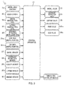
- Control apparatus 31 is connected to swivel-base cameras 7b, boom camera 9b, swivel manipulation tool 18, luffing manipulation tool 19, extension/retraction manipulation tool 20, main drum manipulation tool 21m and sub drum manipulation tool 21s, and is capable of obtaining image i1 from swivel-base cameras 7b and image i2 from boom camera 9b and is also capable of obtaining respective manipulation amounts of swivel manipulation tool 18, luffing manipulation tool 19, main drum manipulation tool 21m and sub drum manipulation tool 21s.
- Control apparatus 31 is connected to terminal-side control apparatus 41 of manipulation terminal 32 and is capable of obtaining a control signal from manipulation terminal 32.
- Control apparatus 31 is connected to swivel valve 23, extension/retraction valve 24, luffing valve 25, main valve 26m and sub valve 26s, and is capable of transmitting operation signals Md to swivel valve 23, luffing valve 25, main valve 26m and sub valve 26s.
- Control apparatus 31 is connected to swivel sensor 27, extension/retraction sensor 28, azimuth sensor 29, luffing sensor 30 and winding sensor 43, and is capable of obtaining swivel angle ⁇ z of swivel base 7, extension/retraction length Lb, luffing angle ⁇ x, let-out amount 1(n) and an azimuth of main wire rope 14 or sub wire rope 16 (hereinafter simply referred to as "wire rope").
- Control apparatus 31 generates operation signals Md for swivel manipulation tool 18, luffing manipulation tool 19, main drum manipulation tool 21m and sub drum manipulation tool 21s based on manipulation amounts of the respective manipulation tools.
- Crane 1 configured as described above is capable of moving crane apparatus 6 to any position by causing vehicle 2 to travel. Crane 1 is also capable of increasing a lifting height and/or an operating radius of crane apparatus 6, for example, by luffing up boom 9 to any luffing angle ⁇ x with hydraulic luffing cylinder 12 by means of manipulation of luffing manipulation tool 19 and/or extending boom 9 to any length of boom 9 by means of manipulation of extension/retraction manipulation tool 20. Crane 1 is also capable of carrying load W by hoisting up load W with sub drum manipulation tool 21s and/or the like and causing swivel base 7 to swivel by means of manipulation of swivel manipulation tool 18.
- manipulation terminal 32 is a terminal with which target speed signal Vd relating to a direction and a speed of movement of load W is input.
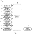
- Manipulation terminal 32 includes: for example, housing 33; suspended-load movement manipulation tool 35, terminal-side swivel manipulation tool 36, terminal-side extension/retraction manipulation tool 37, terminal-side main drum manipulation tool 38m, terminal-side sub drum manipulation tool 38s, terminal-side luffing manipulation tool 39 and terminal-side display apparatus 40 disposed on a manipulation surface of housing 33; and terminal-side control apparatus 41 (see FIGS. 3 and 5 ).
- Manipulation terminal 32 transmits target speed signal Vd of load W that is generated by manipulation of suspended-load movement manipulation tool 35 or any of the manipulation tools to control apparatus 31 of crane 1 (crane apparatus 6).
- Suspended-load movement manipulation tool 35 is a manipulation tool with which an instruction on a direction and a speed of movement of load W in a horizontal plane is input.
- Suspended-load movement manipulation tool 35 is composed of a manipulation stick erected substantially perpendicularly from the manipulation surface of housing 33 and a non-illustrated sensor that detects a tilt direction and a tilt amount of the manipulation stick.
- Suspended-load movement manipulation tool 35 is configured such that the manipulation stick can be manipulated to be tilted in any direction.
- Suspended-load movement manipulation tool 35 is configured to transmit a manipulation signal on the tilt direction and the tilt amount of the manipulation stick detected by the non-illustrated sensor with an upward direction in plan view of the manipulation surface (hereinafter simply referred to as "upward direction") as a direction of extension of boom 9, to terminal-side control apparatus 41 (see FIG. 2 ).
- Terminal-side swivel manipulation tool 36 is a manipulation tool with which an instruction on a swivel direction and a speed of crane apparatus 6 is input.
- Terminal-side extension/retraction manipulation tool 37 is a manipulation tool with which an instruction on extension/retraction and a speed of boom 9 is input.
- Terminal-side main drum manipulation tool 38m (terminal-side sub drum manipulation tool 38s) is a manipulation tool with which an instruction on a rotation direction and a speed of main winch 13 is input.
- Terminal-side luffing manipulation tool 39 is a manipulation tool with which an instruction on luffing and a speed of boom 9 is input.
- Each manipulation tool is composed of a manipulation stick substantially perpendicularly erected from the manipulation surface of housing 33 and a non-illustrated sensor that detects a tilt direction and a tilt amount of the manipulation stick.
- Each manipulation tool is configured to be tiltable to one side and the other side.
- Terminal-side display apparatus 40 displays various kinds of information such as postural information of crane 1, information on load W and/or the like.
- Terminal-side display apparatus 40 is configured by an image display apparatus such as a liquid-crystal screen or the like.
- Terminal-side display apparatus 40 is provided on the manipulation surface of housing 33.
- Terminal-side display apparatus 40 displays an azimuth with the direction of extension of boom 9 as the upward direction in plan view of terminal-side display apparatus 40.
- terminal-side control apparatus 41 which is a control section, controls manipulation terminal 32.
- Terminal-side control apparatus 41 is disposed inside housing 33 of manipulation terminal 32.
- terminal-side control apparatus 41 may have a configuration in which a CPU, a ROM, a RAM, an HDD and/or the like are connected to one another via a bus or may be composed of a one-chip LSI or the like.
- Terminal-side control apparatus 41 stores various programs and/or data in order to control operation of suspended-load movement manipulation tool 35, terminal-side swivel manipulation tool 36, terminal-side extension/retraction manipulation tool 37, terminal-side main drum manipulation tool 38m, terminal-side sub drum manipulation tool 38s, terminal-side luffing manipulation tool 39, terminal-side display apparatus 40 and/or the like.
- Terminal-side control apparatus 41 is connected to suspended-load movement manipulation tool 35, terminal-side swivel manipulation tool 36, terminal-side extension/retraction manipulation tool 37, terminal-side main drum manipulation tool 38m, terminal-side sub drum manipulation tool 38s and terminal-side luffing manipulation tool 39, and is capable of obtaining manipulation signals each including a tilt direction and a tilt amount of the manipulation stick of the relevant manipulation tool.
- Terminal-side control apparatus 41 is capable of generating target speed signal Vd of load W from manipulation signals of the respective sticks, the manipulation signals being obtained from the respective sensors of terminal-side swivel manipulation tool 36, terminal-side extension/retraction manipulation tool 37, terminal-side main drum manipulation tool 38m, terminal-side sub drum manipulation tool 38s and terminal-side luffing manipulation tool 39. Also, terminal-side control apparatus 41 is connected to control apparatus 31 of crane apparatus 6 wirelessly or via a wire, and is capable of transmitting generated target speed signal Vd of load W to control apparatus 31 of crane apparatus 6.
- terminal-side control apparatus 41 obtains a manipulation signal on a tilt direction and a tilt amount of a tilt to northwest, which is the direction in which tilt angle ⁇ 2 is 45°, from north, which is an extension direction of boom 9, from the non-illustrated sensor of suspended-load movement manipulation tool 35. Furthermore, terminal-side control apparatus 41 computes target speed signal Vd for moving load W to northwest at a speed according to the tilt amount from the obtained manipulation signal, every unit time t. Manipulation terminal 32 transmits computed target speed signal Vd to control apparatus 31 of crane apparatus 6 every unit time t (see FIG. 4 ).
- control apparatus 31 Upon receiving target speed signal Vd from manipulation terminal 32 every unit time t, control apparatus 31 computes target course signal Pd of load W based on an azimuth of the tip of boom 9, the azimuth being obtained from azimuth sensor 29. Furthermore, control apparatus 31 computes target position coordinate p(n+1) of load W, which is a target position of load W, from target course signal Pd. Control apparatus 31 generate respective operation signals Md for swivel valve 23, extension/retraction valve 24, luffing valve 25, main valve 26m and sub valve 26s to move load W to target position coordinate p(n+1) (see FIG. 7 ). Crane 1 moves load W toward northwest, which is the tilt direction of suspended-load movement manipulation tool 35, at a speed according to the tilt amount. In this case, crane 1 controls hydraulic swivel motor 8, a hydraulic extension/retraction cylinder, hydraulic luffing cylinder 12, the main hydraulic motor and/or the like based on the operation signals Md.
- Crane 1 configured as described above obtains target speed signal Vd on a moving direction and a speed based on a direction of manipulation of suspended-load movement manipulation tool 35 with reference to the extension direction of boom 9, from manipulation terminal 32 every unit time and determines target position coordinate p(n+1) of load W, and prevents the operator from lose recognition of a direction of operation of crane apparatus 6 relative to a direction of manipulation of suspended-load movement manipulation tool 35.
- a direction of manipulation of suspended-load movement manipulation tool 35 and a direction of movement of load W are computed based on the extension direction of boom 9, which is a common reference. Consequently, it is possible to easily and simply manipulate crane apparatus 6.
- manipulation terminal 32 is provided inside cabin 17, but may be configured as a remote manipulation terminal that can remotely be manipulated from the outside of cabin 17, by providing a terminal-side radio device.
- Control apparatus 31 includes target course computation section 31a, boom position computation section 31b and operation signal generation section 31c. Also, control apparatus 31 is configured to be capable of obtaining current positional information of load W using the set of swivel-base cameras 7b on the opposite, left and right, sides of the front of swivel base 7 as a stereo camera, which is a load position detection section (see FIG. 2 ).
- target course computation section 31a is a part of control apparatus 31 and converts target speed signal Vd for load W into target course signal Pd ⁇ for load W.
- Target course computation section 31a can obtain target speed signal Vd for load W, which is composed of a moving direction and a speed of load W, from manipulation terminal 32 every unit time t.
- target course computation section 31a can compute target course signals Pd ⁇ for an x-axis direction, a y-axis direction and a z-axis direction of load W for each unit time t, by integrating obtained target speed signal Vd.
- the suffix " ⁇ " is a sign representing any of the x-axis direction, the y-axis direction and the z-axis direction.
- Boom position computation section 31b is a part of control apparatus 31 and computes a position coordinate of the tip of boom 9 from postural information of boom 9 and target course signal Pd ⁇ for load W. Boom position computation section 31b can obtain target course signal Pd ⁇ from target course computation section 31a.
- Boom position computation section 31b can obtain swivel angle ⁇ z(n) of swivel base 7 from swivel sensor 27, obtain extension/retraction length lb(n) from extension/retraction sensor 28, obtain luffing angle ⁇ x(n) from luffing sensor 30, obtain let-out amount 1(n) of main wire rope 14 or sub wire rope 16 (hereinafter simply referred to as "wire rope") from winding sensor 43 and obtain current positional information of load W from an image of load W taken by the set of swivel-base cameras 7b disposed on the opposite, left and right, sides of the front of swivel base 7 (see FIG. 2 ).
- Boom position computation section 31b can compute current position coordinate p(n) of load W from the obtained current positional information of load W and compute current position coordinate q(n) of the tip (position from which the wire rope is let out) of boom 9 (hereinafter simply referred to as "current position coordinate q(n) of boom 9"), which is a current position of the tip of boom 9, from obtained swivel angle ⁇ z(n), obtained extension/retraction length lb(n) and obtained luffing angle ⁇ x(n). Also, boom position computation section 31b can compute let-out amount 1(n) of the wire rope from current position coordinate p(n) of load W and current position coordinate q(n) of boom 9.
- boom position computation section 31b can compute target position coordinate p(n+1) of load W, which is a position of load W after a lapse of unit time t, from target course signal Pd. Furthermore, boom position computation section 31b can compute direction vector e(n+1) of the wire rope from which load W is suspended, from current position coordinate p(n) of load W and target position coordinate p(n+1) of load W, which is a position of load W. Boom position computation section 31b is configured to compute target position coordinate q(n+1) of boom 9, which is a position of the tip of boom 9 after the lapse of unit time t, from target position coordinate p(n+1) of load W and direction vector e(n+1) of the wire rope, using inverse dynamics.
- Operation signal generation section 31c is a part of control apparatus 31 and generates operation signals Md for the actuators from target position coordinate q(n+1) of boom 9 after the lapse of unit time t. Operation signal generation section 31c can obtain target position coordinate q(n+1) of boom 9 after the lapse of unit time t from boom position computation section 31b. Operation signal generation section 31c is configured to generate operation signals Md for swivel valve 23, extension/retraction valve 24, luffing valve 25, and main valve 26m or sub valve 26s.
- control apparatus 31 determines an inverse dynamics model for crane 1 in order to compute target position coordinate q(n+1) of the tip of boom 9.
- the inverse dynamics model is defined on a XYZ coordinate system and reference position O is a center of swivel of crane 1.
- Control apparatus 31 defines q, p, 1b, ⁇ x, ⁇ z, 1, f and e, respectively, in the inverse dynamics model.
- the sign q denotes, for example, current position coordinate q(n) of the tip of boom 9 and p denotes, for example, current position coordinate p(n) of load W.
- the sign 1b denotes, for example, extension/retraction length lb(n) of boom 9 and ⁇ x denotes, for example, luffing angle ⁇ x(n), and ⁇ z denotes, for example, swivel angle ⁇ z(n).
- the sign 1 denotes, for example, let-out amount 1(n) of the wire rope, f denotes tension f of the wire rope, and e denotes, for example, direction vector e(n) of the wire rope.
- Direction vector e(n) of the wire rope is computed according to Expression 5 below.
- Direction vector e(n) of the wire rope is a vector of tension f (see Expression 2) of the wire rope for a unit length.
- Tension f of the wire rope is computed by subtracting the gravitational acceleration from an acceleration of load W, the acceleration being computed from current position coordinate p(n) of load W and target position coordinate p(n+1) of load W after the lapse of unit time t.
- Target position coordinate q(n+1) of boom 9, which is a target position of the tip of boom 9 after the lapse of unit time t, is computed from Expression 6 representing Expression 2 as a function of n.
- ⁇ denotes swivel angle ⁇ z(n) of boom 9.
- Target position coordinate q(n+1) of boom 9 is computed from let-out amount 1(n) of the wire rope, target position coordinate p(n+1) of load W and direction vector e(n+1) using inverse dynamics.
- Low-pass filter Lp attenuates frequencies that are equal to or lower than a predetermined frequency.
- Low-pass filter Lp curbs occurrence of a singular point (abrupt positional change) caused by a differential operation, by applying low-pass filter Lp to target speed signal Vd for load W.
- Low-pass filter Lp is formed by transfer function G(s) in Expression 1.
- Transfer function G(s) is expressed in the form of a partial fraction decomposition where each of A, B and C is a coefficient, each of w ⁇ 1, w ⁇ 2, w ⁇ 3 and w ⁇ 4 is a weight coefficient and s is a differentiation element.
- the suffix " ⁇ " is a sign representing any of the x-axis, the y-axis and the z-axis.
- transfer function G(s) in Expression 1 is set for each of the x-axis, the y-axis and the z-axis. In this way, each transfer function G(s) can be expressed as one resulting from superimposition of first-order lag transfer functions.
- Target speed signal Vd for load W is converted into later-described target course signals Pd2 ⁇ by being multiplied by respective transfer functions G(s) of low-pass filter Lp.
- Target position coordinate p(n+1) of load W is computed from target course signals Pd2 ⁇ .
- G s w ⁇ 1 s + w ⁇ 2 As + 1 + w ⁇ 3 Bs + 1 + w ⁇ 4 Cs + 1 ... (Expression 1)
- feedback control section 42a performs control based on a difference between a current position and a target position of a load.
- Feedback control section 42a includes target course computation section 31a, boom position computation section 31b and operation signal generation section 31c that are connected in series (see connection sign D) and is configured to feed current position coordinate p(n) of load W back to target course signals Pd ⁇ for load W.
- feedback control section 42a Upon obtainment of target speed signal Vd for load W, feedback control section 42a computes target course signals Pd ⁇ for the x-axis direction, the y-axis direction and the z-axis direction of load W in target course computation section 31a. Next, feedback control section 42a computes current position coordinate p(n) of load W from current position information of load W, the current position information being obtained from swivel-base cameras 7b, and (negatively) feeds current position coordinate p(n) back to the target course signals Pd ⁇ . Feedback control section 42a corrects target course signals Pd ⁇ based on a difference of current position coordinate p(n) of load W from target course signals Pd ⁇ to compute target course signals Pd1 ⁇ .
- feedback control section 42a computes target position coordinate q(n+1) of boom 9 after a lapse of unit time t from later-described target course signals Pd2 ⁇ corrected on the upstream side, information pieces (swivel angle ⁇ z(n), extension/retraction length lb(n), luffing angle ⁇ x(n) and let-out amount 1(n)) of a posture of crane 1 obtained from the respective sensors and current position information of load W obtained from swivel-base cameras 7b, using inverse dynamics in boom position computation section 31b.
- feedback control section 42a generates operation signals Md for the respective actuators from target position coordinate q(n+1) of boom 9 calculated by boom position computation section 31b, in operation signal generation section 31c.
- Feedback control section 42a makes the actuators of crane 1 operate according to operation signals Md to move load W.
- Feedforward control section 42b performs control to apply low-pass filter Lp to target speed signal Vd of load W.
- each transfer function G(s) of fourth-order low-pass filter Lp is formed as a transfer function formed of four first-order models, first model G1(s), second model G2(s), third model G3(s) and fourth model G4(s), and the respective first-order models, each of which serves as a sub system, are combined in series.
- Feedforward control section 42b computes target course signals Pd2 ⁇ with predetermined frequency components curbed, by applying low-pass filter Lp to target course signals Pd1 ⁇ for load W corrected by feedback control section 42a.
- first model G1 (s), second model G2(s), third model G3(s) and fourth model G4(s), which are first-order lag transfer functions resulting from partial fraction decomposition of transfer function G(s) of fourth-order low-pass filter Lp, are superimposed on one another.
- weight coefficient w ⁇ 1 is assigned to first model G1(s)
- weight coefficient w ⁇ 2 is assigned to second model G2(s)
- weight coefficient w ⁇ 3 is assigned to third model G3(s)
- weight coefficient w ⁇ 4 is assigned to fourth model G4(s).
- Feedforward control section 42b adjusts weight coefficients w ⁇ 1, w ⁇ 2, w ⁇ 3 and w ⁇ 4 of the respective models based on relevant target course signal Pd1 ⁇ for load W corrected by feedback control section 42a.
- feedforward control section 42b Upon obtainment of target speed signal Vd for load W, feedforward control section 42b applies first model G1(s) having weight coefficient w ⁇ 1 to target speed signal Vd. Since in the present embodiment, first model G1(s) is an integration element, relevant target course signal Pd ⁇ for load W is computed from target speed signal Vd for load W. Next, feedforward control section 42b applies second model G2(s) having weight coefficient w ⁇ 2 to an output from first model G1(s). Next, feedforward control section 42b applies third model G3(s) having weight coefficient w ⁇ 3 to an output from second model G2(s). Next, feedforward control section 42b applies fourth model G4(s) having weight coefficient w ⁇ 4 to an output from third model G3(s).
- feedforward control section 42b computes target course signal Pd2 ⁇ by adding up the outputs of the respective first-order models and further correcting target course signal Pd1 ⁇ for load W corrected by feedback control section 42a.
- control system 42 of crane 1 further corrects target course signal Pd1 ⁇ of load W corrected by feedback control section 42a, via feedforward control section 42b.
- control system 42 of crane 1 computes target position coordinate q(n+1) of boom 9 from target course signals Pd2 ⁇ .
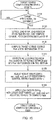
- step S100 control system 42 starts target-course computation process A and makes the control proceed to step S110 (see FIG. 10 ). Then, upon completion of target-course computation process A, the control proceeds to step S200 (see FIG. 9 ).
- step S200 control system 42 starts boom-position computation process B and makes the control proceed to step S210 (see FIG. 11 ). Then, upon completion of boom-position computation process B, the control proceeds to step S300 (see FIG. 9 ).
- step S300 control system 42 starts operation-signal generation process C and makes the control proceed to step S310 (see FIG. 12 ). Then, upon completion of operation-signal generation process C, the control proceeds to step S100 (see FIG. 9 ).
- control system 42 determines whether or not target speed signal Vd for load W is obtained by target course computation section 31a of control apparatus 31.
- control system 42 makes the control proceed to S120.
- control system 42 makes the control proceed to S110.
- control system 42 causes an image of load W to be taken using the set of swivel-base cameras 7b and computes current position coordinate p(n) of load W with arbitrarily-determined reference position O (for example, a center of swiveling of boom 9) as an origin, and makes the control proceed to step S130.
- arbitrarily-determined reference position O for example, a center of swiveling of boom 9)
- control system 42 computes target course signals Pd ⁇ for load W by integrating target speed signal Vd for load W, target speed signal Vd being obtained by target course computation section 31a, and makes the control proceed to step S140.
- control system 42 corrects target course signals Pd ⁇ based on a difference between current position coordinate p(n) of load W and target course signals Pd ⁇ via feedback control section 42a to compute target course signals Pd1 ⁇ , and makes the control proceed to step S150.
- control system 42 adjusts weight coefficients w ⁇ 1, w ⁇ 2, w ⁇ 3 and w ⁇ 4 of the respective first-order models (see FIG. 8 ) of each transfer function G(s) of low-pass filter Lp based on relevant target course signal Pd1 ⁇ via feedforward control section 42b, and makes the control proceed to step S160.
- control system 42 applies low-pass filter Lp with weight coefficients w ⁇ 1, w ⁇ 2, w ⁇ 3 and w ⁇ 4 of the respective models adjusted to target course signals Pd1 ⁇ to compute target course signals Pd2 ⁇ , and ends target-course computation process A and makes the control proceed to step S200 (see FIG. 9 ).
- control system 42 computes current position coordinate q(n) of the tip of boom 9 from obtained swivel angle ⁇ z(n) of swivel base 7, obtained extension/retraction length lb(n) and obtained luffing angle ⁇ x(n) of boom 9 via boom position computation section 31b, and makes the control proceed to step S220.
- control system 42 computes let-out amount 1(n) of the wire rope from current position coordinate p(n) of load W and current position coordinate q(n) of boom 9 using Expression 4 above via boom position computation section 31b, and makes the control proceed to step S230.
- control system 42 computes target position coordinate p(n+1) of load W, which is a target position of load W after a lapse of unit time t, from target course signals Pd2 ⁇ with reference to current position coordinate p(n) of load W via boom position computation section 31b, and makes the control proceed to step S240.
- control system 42 computes an acceleration of load W from current position coordinate p(n) of load W and target position coordinate p(n+1) of load W and computes direction vector e(n+1) of the wire rope according to Expression 5 above using the gravitational acceleration via boom position computation section 31b, and makes the control proceed to step S250.
- control system 42 computes target position coordinate q(n+1) of boom 9 from computed let-out amount 1(n) of the wire rope and computed direction vector e(n+1) of the wire rope using Expression 6 via boom position computation section 3 1b, and ends boom position computation process B and makes the control proceed to step S300 (see FIG. 9 ).
- control system 42 computes swivel angle ⁇ z(n+1) of swivel base 7, extension/retraction length Lb(n+1), luffing angle ⁇ x(n+1) and let-out amount 1(n+1) of the wire rope after the lapse of unit time t from target position coordinate q(n+1) of boom 9 via operation signal generation section 31c, and makes the control proceed to step S320.
- control system 42 In step S320, control system 42 generates respective operation signals Md for swivel valve 23, extension/retraction valve 24, luffing valve 25 and main valve 26m or sub valve 26s from computed swivel angle ⁇ z(n+1) of swivel base 7, computed extension/retraction length Lb(n+1), computed luffing angle ⁇ x(n+1) and computed let-out amount 1(n+1) of the wire rope via operation signal generation section 31c, and ends operation signal generation process C and makes the control proceed to step S100 (see FIG. 9 ).
- Control system 42 of crane 1 computes target position coordinate q(n+1) of boom 9, and after a lapse of unit time t, computes direction vector e(n+2) of the wire rope from let-out amount 1(n+1) of the wire rope, current position coordinate p(n+1) of load W and target position coordinate p(n+2) of load W, and further computes target position coordinate q(n+2) of boom 9 after the lapse of unit time t, by repeating target course computation process A, boom position computation process B and operation signal generation process C.
- control system 42 computes direction vector e(n) of the wire rope and sequentially computes target position coordinate q(n+1) of boom 9 unit time t after from current position coordinate p(n+1) of load W, target position coordinate p(n+1) of load W and direction vector e(n) of the wire rope, using inverse dynamics.
- Control system 42 generates operation signals Md based on target position coordinate q(n+1) of boom 9 to control the actuators.
- crane 1 and control system 42 of crane 1 can be regarded as forming a single-layer neural network by using models each having a clear physical characteristic as a plurality of sub systems and multiplying each of outputs of the plurality of sub systems by a relevant weight coefficient.
- Control system 42 of crane 1 controls the actuators based on a difference between current position coordinate p(n) of load W and target course signals Pd ⁇ via feedback control section 42a, and individually adjusts the respective weight coefficients based on the difference between current position coordinate p(n) of load W and target course signals Pd1 ⁇ , using the respective first-order models forming low-pass filter Lp as sub systems, via feedforward control section 42b.
- control system 42 of crane 1 determines the coefficient of low-pass filter Lp while flexibly responding to changes in dynamic characteristic of crane 1.
- a high-order transfer function is adjusted for each first-order model. Consequently, it is possible to, when the actuators are controlled with reference to a load, move the load in a manner intended by an operator while curbing swinging of the load, by learning a dynamic characteristic of crane 1 from movement of the load.
- each of the first-order models of low-pass filter Lp is used as a sub system, but other models each having a clear physical characteristic may be used.
- the present invention is applicable to a crane and a control system for the crane.
Landscapes
- Engineering & Computer Science (AREA)
- Mechanical Engineering (AREA)
- Automation & Control Theory (AREA)
- Control And Safety Of Cranes (AREA)
- Jib Cranes (AREA)
Priority Applications (1)
| Application Number | Priority Date | Filing Date | Title |
|---|---|---|---|
| EP23166434.3A EP4219383A1 (de) | 2018-07-25 | 2019-07-18 | Steuerungssystem für einen kran |
Applications Claiming Priority (2)
| Application Number | Priority Date | Filing Date | Title |
|---|---|---|---|
| JP2018139849A JP7172243B2 (ja) | 2018-07-25 | 2018-07-25 | クレーンおよびクレーンの制御システム |
| PCT/JP2019/028259 WO2020022181A1 (ja) | 2018-07-25 | 2019-07-18 | クレーンおよびクレーンの制御システム |
Related Child Applications (2)
| Application Number | Title | Priority Date | Filing Date |
|---|---|---|---|
| EP23166434.3A Division EP4219383A1 (de) | 2018-07-25 | 2019-07-18 | Steuerungssystem für einen kran |
| EP23166434.3A Division-Into EP4219383A1 (de) | 2018-07-25 | 2019-07-18 | Steuerungssystem für einen kran |
Publications (3)
| Publication Number | Publication Date |
|---|---|
| EP3828120A1 true EP3828120A1 (de) | 2021-06-02 |
| EP3828120A4 EP3828120A4 (de) | 2022-10-12 |
| EP3828120B1 EP3828120B1 (de) | 2023-11-29 |
Family
ID=69181545
Family Applications (2)
| Application Number | Title | Priority Date | Filing Date |
|---|---|---|---|
| EP23166434.3A Pending EP4219383A1 (de) | 2018-07-25 | 2019-07-18 | Steuerungssystem für einen kran |
| EP19839926.3A Active EP3828120B1 (de) | 2018-07-25 | 2019-07-18 | Kran und steuersystem für einen kran |
Family Applications Before (1)
| Application Number | Title | Priority Date | Filing Date |
|---|---|---|---|
| EP23166434.3A Pending EP4219383A1 (de) | 2018-07-25 | 2019-07-18 | Steuerungssystem für einen kran |
Country Status (5)
| Country | Link |
|---|---|
| US (1) | US11858784B2 (de) |
| EP (2) | EP4219383A1 (de) |
| JP (1) | JP7172243B2 (de) |
| CN (1) | CN112424110B (de) |
| WO (1) | WO2020022181A1 (de) |
Cited By (1)
| Publication number | Priority date | Publication date | Assignee | Title |
|---|---|---|---|---|
| AT17996U1 (de) * | 2022-05-13 | 2023-10-15 | Palfinger Ag | Verfahren zum Bewegen einer Hebevorrichtung |
Families Citing this family (3)
| Publication number | Priority date | Publication date | Assignee | Title |
|---|---|---|---|---|
| EP3907171B1 (de) * | 2020-05-06 | 2022-07-06 | Hiab AB | Kran, fahrzeug und verfahren für den kran |
| JP2022068037A (ja) * | 2020-10-21 | 2022-05-09 | 株式会社タダノ | クレーン、クレーンの特性変化判定装置、及びクレーンの特性変化判定システム |
| CN113800415B (zh) * | 2021-09-24 | 2023-03-24 | 徐工集团工程机械股份有限公司建设机械分公司 | 一种起重机卷扬起升系统的自适应控制方法 |
Family Cites Families (15)
| Publication number | Priority date | Publication date | Assignee | Title |
|---|---|---|---|---|
| JPS5414389B2 (de) * | 1973-04-02 | 1979-06-06 | ||
| JPH07115838B2 (ja) * | 1989-02-13 | 1995-12-13 | 株式会社彦間製作所 | クレーンの旋回規制機構 |
| JPH0781876A (ja) | 1993-09-20 | 1995-03-28 | Nippon Steel Corp | 懸垂式クレーンの振止め・位置制御方法 |
| JP3277802B2 (ja) * | 1996-03-28 | 2002-04-22 | 日本鋼管株式会社 | クレーン |
| US5785191A (en) * | 1996-05-15 | 1998-07-28 | Sandia Corporation | Operator control systems and methods for swing-free gantry-style cranes |
| US7426423B2 (en) | 2003-05-30 | 2008-09-16 | Liebherr-Werk Nenzing—GmbH | Crane or excavator for handling a cable-suspended load provided with optimised motion guidance |
| CN100425520C (zh) * | 2003-08-05 | 2008-10-15 | 新东工业株式会社 | 起重机及其控制器 |
| DE102007039408A1 (de) * | 2007-05-16 | 2008-11-20 | Liebherr-Werk Nenzing Gmbh | Kransteuerung, Kran und Verfahren |
| JP5215725B2 (ja) * | 2008-05-13 | 2013-06-19 | 株式会社キトー | 走行クレーンの操作制御装置、操作制御方法 |
| JP5342298B2 (ja) | 2009-03-30 | 2013-11-13 | 株式会社タダノ | 作業機の遠隔操作装置及び遠隔操作方法 |
| DE102011102025A1 (de) * | 2011-05-19 | 2012-11-22 | Liebherr-Werk Nenzing Gmbh | Kransteuerung |
| DE102012004803A1 (de) | 2012-03-09 | 2013-09-12 | Liebherr-Werk Nenzing Gmbh | Kransteuerung mit Antriebsbeschränkung |
| DE102012004914A1 (de) * | 2012-03-09 | 2013-09-12 | Liebherr-Werk Nenzing Gmbh | Kransteuerung mit Seilkraftmodus |
| US9718650B2 (en) * | 2014-07-16 | 2017-08-01 | Institute of Nuclear Energy Research, Atomic Energy Council, Executive Yuan, R.O.C. | Control device using image tracking technology for controlling overhead crane system |
| JP6700679B2 (ja) | 2015-06-04 | 2020-05-27 | キヤノン株式会社 | 制御方法、物品の製造方法、ロボット装置、制御プログラム及び記録媒体 |
-
2018
- 2018-07-25 JP JP2018139849A patent/JP7172243B2/ja active Active
-
2019
- 2019-07-18 EP EP23166434.3A patent/EP4219383A1/de active Pending
- 2019-07-18 EP EP19839926.3A patent/EP3828120B1/de active Active
- 2019-07-18 US US17/257,635 patent/US11858784B2/en active Active
- 2019-07-18 WO PCT/JP2019/028259 patent/WO2020022181A1/ja active Application Filing
- 2019-07-18 CN CN201980047796.7A patent/CN112424110B/zh active Active
Cited By (1)
| Publication number | Priority date | Publication date | Assignee | Title |
|---|---|---|---|---|
| AT17996U1 (de) * | 2022-05-13 | 2023-10-15 | Palfinger Ag | Verfahren zum Bewegen einer Hebevorrichtung |
Also Published As
| Publication number | Publication date |
|---|---|
| US11858784B2 (en) | 2024-01-02 |
| JP2020015589A (ja) | 2020-01-30 |
| JP7172243B2 (ja) | 2022-11-16 |
| CN112424110B (zh) | 2023-05-05 |
| EP4219383A1 (de) | 2023-08-02 |
| WO2020022181A1 (ja) | 2020-01-30 |
| EP3828120B1 (de) | 2023-11-29 |
| CN112424110A (zh) | 2021-02-26 |
| US20210284507A1 (en) | 2021-09-16 |
| EP3828120A4 (de) | 2022-10-12 |
Similar Documents
| Publication | Publication Date | Title |
|---|---|---|
| EP3828120B1 (de) | Kran und steuersystem für einen kran | |
| US11718510B2 (en) | Crane and crane control method | |
| EP3822219A1 (de) | Kran | |
| EP3831765A1 (de) | Kran | |
| EP4043967A1 (de) | Steuersystem und kran | |
| EP4082957A1 (de) | Steuersystem für eine arbeitsmaschine und kran | |
| EP3868699B1 (de) | Kranvorrichtung | |
| EP3822221B1 (de) | Kran und kransteuerungsverfahren | |
| EP4234472A1 (de) | Kran, vorrichtung zur bestimmung der kraneigenschaftsänderung und system zur bestimmung der kraneigenschaftsänderung | |
| WO2022186382A1 (ja) | 故障予兆検出システムおよび作業車 |
Legal Events
| Date | Code | Title | Description |
|---|---|---|---|
| STAA | Information on the status of an ep patent application or granted ep patent |
Free format text: STATUS: THE INTERNATIONAL PUBLICATION HAS BEEN MADE |
|
| STAA | Information on the status of an ep patent application or granted ep patent |
Free format text: STATUS: THE INTERNATIONAL PUBLICATION HAS BEEN MADE |
|
| PUAI | Public reference made under article 153(3) epc to a published international application that has entered the european phase |
Free format text: ORIGINAL CODE: 0009012 |
|
| STAA | Information on the status of an ep patent application or granted ep patent |
Free format text: STATUS: REQUEST FOR EXAMINATION WAS MADE |
|
| 17P | Request for examination filed |
Effective date: 20210215 |
|
| AK | Designated contracting states |
Kind code of ref document: A1 Designated state(s): AL AT BE BG CH CY CZ DE DK EE ES FI FR GB GR HR HU IE IS IT LI LT LU LV MC MK MT NL NO PL PT RO RS SE SI SK SM TR |
|
| DAV | Request for validation of the european patent (deleted) | ||
| DAX | Request for extension of the european patent (deleted) | ||
| A4 | Supplementary search report drawn up and despatched |
Effective date: 20220914 |
|
| RIC1 | Information provided on ipc code assigned before grant |
Ipc: B66C 23/42 20060101ALI20220908BHEP Ipc: B66C 13/48 20060101ALI20220908BHEP Ipc: B66C 13/46 20060101ALI20220908BHEP Ipc: B66C 23/88 20060101ALI20220908BHEP Ipc: B66C 13/06 20060101ALI20220908BHEP Ipc: B66C 13/22 20060101AFI20220908BHEP |
|
| GRAP | Despatch of communication of intention to grant a patent |
Free format text: ORIGINAL CODE: EPIDOSNIGR1 |
|
| STAA | Information on the status of an ep patent application or granted ep patent |
Free format text: STATUS: GRANT OF PATENT IS INTENDED |
|
| INTG | Intention to grant announced |
Effective date: 20230630 |
|
| GRAS | Grant fee paid |
Free format text: ORIGINAL CODE: EPIDOSNIGR3 |
|
| GRAA | (expected) grant |
Free format text: ORIGINAL CODE: 0009210 |
|
| STAA | Information on the status of an ep patent application or granted ep patent |
Free format text: STATUS: THE PATENT HAS BEEN GRANTED |
|
| AK | Designated contracting states |
Kind code of ref document: B1 Designated state(s): AL AT BE BG CH CY CZ DE DK EE ES FI FR GB GR HR HU IE IS IT LI LT LU LV MC MK MT NL NO PL PT RO RS SE SI SK SM TR |
|
| REG | Reference to a national code |
Ref country code: GB Ref legal event code: FG4D |
|
| REG | Reference to a national code |
Ref country code: CH Ref legal event code: EP |
|
| REG | Reference to a national code |
Ref country code: DE Ref legal event code: R096 Ref document number: 602019042539 Country of ref document: DE |
|
| REG | Reference to a national code |
Ref country code: IE Ref legal event code: FG4D |
|
| REG | Reference to a national code |
Ref country code: LT Ref legal event code: MG9D |
|
| REG | Reference to a national code |
Ref country code: NL Ref legal event code: MP Effective date: 20231129 |
|
| PG25 | Lapsed in a contracting state [announced via postgrant information from national office to epo] |
Ref country code: GR Free format text: LAPSE BECAUSE OF FAILURE TO SUBMIT A TRANSLATION OF THE DESCRIPTION OR TO PAY THE FEE WITHIN THE PRESCRIBED TIME-LIMIT Effective date: 20240301 |
|
| PG25 | Lapsed in a contracting state [announced via postgrant information from national office to epo] |
Ref country code: IS Free format text: LAPSE BECAUSE OF FAILURE TO SUBMIT A TRANSLATION OF THE DESCRIPTION OR TO PAY THE FEE WITHIN THE PRESCRIBED TIME-LIMIT Effective date: 20240329 |
|
| PG25 | Lapsed in a contracting state [announced via postgrant information from national office to epo] |
Ref country code: LT Free format text: LAPSE BECAUSE OF FAILURE TO SUBMIT A TRANSLATION OF THE DESCRIPTION OR TO PAY THE FEE WITHIN THE PRESCRIBED TIME-LIMIT Effective date: 20231129 |
|
| PG25 | Lapsed in a contracting state [announced via postgrant information from national office to epo] |
Ref country code: ES Free format text: LAPSE BECAUSE OF FAILURE TO SUBMIT A TRANSLATION OF THE DESCRIPTION OR TO PAY THE FEE WITHIN THE PRESCRIBED TIME-LIMIT Effective date: 20231129 |
|
| PG25 | Lapsed in a contracting state [announced via postgrant information from national office to epo] |
Ref country code: LT Free format text: LAPSE BECAUSE OF FAILURE TO SUBMIT A TRANSLATION OF THE DESCRIPTION OR TO PAY THE FEE WITHIN THE PRESCRIBED TIME-LIMIT Effective date: 20231129 Ref country code: IS Free format text: LAPSE BECAUSE OF FAILURE TO SUBMIT A TRANSLATION OF THE DESCRIPTION OR TO PAY THE FEE WITHIN THE PRESCRIBED TIME-LIMIT Effective date: 20240329 Ref country code: GR Free format text: LAPSE BECAUSE OF FAILURE TO SUBMIT A TRANSLATION OF THE DESCRIPTION OR TO PAY THE FEE WITHIN THE PRESCRIBED TIME-LIMIT Effective date: 20240301 Ref country code: ES Free format text: LAPSE BECAUSE OF FAILURE TO SUBMIT A TRANSLATION OF THE DESCRIPTION OR TO PAY THE FEE WITHIN THE PRESCRIBED TIME-LIMIT Effective date: 20231129 Ref country code: BG Free format text: LAPSE BECAUSE OF FAILURE TO SUBMIT A TRANSLATION OF THE DESCRIPTION OR TO PAY THE FEE WITHIN THE PRESCRIBED TIME-LIMIT Effective date: 20240229 |
|
| REG | Reference to a national code |
Ref country code: AT Ref legal event code: MK05 Ref document number: 1635940 Country of ref document: AT Kind code of ref document: T Effective date: 20231129 |
|
| PG25 | Lapsed in a contracting state [announced via postgrant information from national office to epo] |
Ref country code: NL Free format text: LAPSE BECAUSE OF FAILURE TO SUBMIT A TRANSLATION OF THE DESCRIPTION OR TO PAY THE FEE WITHIN THE PRESCRIBED TIME-LIMIT Effective date: 20231129 |