EP3828118A1 - Elevator guiding device and elevator system comprising the same - Google Patents
Elevator guiding device and elevator system comprising the same Download PDFInfo
- Publication number
- EP3828118A1 EP3828118A1 EP20210512.8A EP20210512A EP3828118A1 EP 3828118 A1 EP3828118 A1 EP 3828118A1 EP 20210512 A EP20210512 A EP 20210512A EP 3828118 A1 EP3828118 A1 EP 3828118A1
- Authority
- EP
- European Patent Office
- Prior art keywords
- elevator
- biased
- guiding device
- elevator car
- guiding
- Prior art date
- Legal status (The legal status is an assumption and is not a legal conclusion. Google has not performed a legal analysis and makes no representation as to the accuracy of the status listed.)
- Withdrawn
Links
Images
Classifications
-
- B—PERFORMING OPERATIONS; TRANSPORTING
- B66—HOISTING; LIFTING; HAULING
- B66B—ELEVATORS; ESCALATORS OR MOVING WALKWAYS
- B66B7/00—Other common features of elevators
- B66B7/02—Guideways; Guides
- B66B7/04—Riding means, e.g. Shoes, Rollers, between car and guiding means, e.g. rails, ropes
- B66B7/041—Riding means, e.g. Shoes, Rollers, between car and guiding means, e.g. rails, ropes including active attenuation system for shocks, vibrations
- B66B7/042—Riding means, e.g. Shoes, Rollers, between car and guiding means, e.g. rails, ropes including active attenuation system for shocks, vibrations with rollers, shoes
-
- B—PERFORMING OPERATIONS; TRANSPORTING
- B66—HOISTING; LIFTING; HAULING
- B66B—ELEVATORS; ESCALATORS OR MOVING WALKWAYS
- B66B11/00—Main component parts of lifts in, or associated with, buildings or other structures
- B66B11/02—Cages, i.e. cars
- B66B11/026—Attenuation system for shocks, vibrations, imbalance, e.g. passengers on the same side
- B66B11/0266—Passive systems
- B66B11/0273—Passive systems acting between car and supporting frame
-
- B—PERFORMING OPERATIONS; TRANSPORTING
- B66—HOISTING; LIFTING; HAULING
- B66B—ELEVATORS; ESCALATORS OR MOVING WALKWAYS
- B66B7/00—Other common features of elevators
- B66B7/02—Guideways; Guides
- B66B7/04—Riding means, e.g. Shoes, Rollers, between car and guiding means, e.g. rails, ropes
- B66B7/046—Rollers
Definitions
- the present disclosure relates to the technical field of elevators, and particularly to an elevator guiding device and an elevator system comprising the elevator guiding device.
- Elevators have received wide application in modern society and can bring great convenience to people's work and daily life. Although various types of elevator devices, apparatuses or systems have already been provided in the prior art to meet people's various different application needs, these existing elevator products still have some drawbacks and shortcomings in aspects such as structural configuration, installation and use, work performance, manufacturing cost, safety and reliability. For example, for existing elevator guiding devices that provide guidance for elevator cars, further structural improvements and optimizations can be made.
- the present disclosure provides an elevator guiding device and an elevator system including the elevator guiding device, so as to resolve or at least alleviate one or more of the problems described above as well as problems of other aspects existing in the prior art.
- an elevator guiding device configured to be installed on an elevator car and includes:
- the elastic member and the stop member are a spring and an annular sleeve sleeved over the connection member respectively, and the end of the annular sleeve facing the biasing part is spaced apart from the biased member by a preset distance.
- the spring is a coil spring, and an outer diameter of the annular sleeve is smaller than an inner diameter of the coil spring.
- the stop member is a protrusion provided along a circumferential direction on at least a part of an outer surface of the connection member, and the protrusion is configured not to interfere with the elastic member and the end of the protrusion facing the biased member is spaced apart from the biased member by a preset distance.
- connection member is a bolt with a nut installed at an end, and the respective ends of the elastic member and the stop member facing the nut both abut against the nut.
- the biased member is installed on the top, side and/or bottom of the elevator car.
- the elevator guiding device further includes a bracket installed on the top, side and/or bottom of the elevator car, and the biased member is installed on the bracket.
- connection member and the elastic member are made of a metal material
- the stop member is made of an elastic material
- the biased member has a first end, and a second end fixed relative to the elevator car
- the guiding and contacting member is a roller rotatably installed on the biased member and located between the first end and the second end
- the biased member is arranged to be pivotable around a fixed point of the second end on the elevator car after the roller contacts the elevator guiding rail
- the connection member is installed at the first end of the biased member.
- an elevator system which includes:
- the elevator guiding device has a compact structure and is easy to install, manufacture and maintain.
- the use of the present disclosure can effectively reduce the number of components in the elevator guiding device, optimize spatial layout of the system, and reduce product costs, while providing good work performance and providing sufficient guarantee for the safe and reliable operation of the elevator.
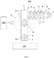
- FIG. 1 schematically shows the general composition of an embodiment of an elevator guiding device according to the present disclosure.
- the elevator guiding device is configured to be installed on an elevator car so as to guide the elevator car when the elevator car is running in an unbalanced loaded state along an elevator guiding rail, thereby preventing or reducing the occurrence of elevator car swaying, turning over and the like.
- the elevator guiding device 100 may include a biased member 1, a guiding and contacting member 2 and a connection member 3, which are realized in structural forms of a pivoting arm, a roller and a bolt respectively.
- the elevator guiding device 100 is also generally called a "roll guide" in the industry, and the present disclosure will be described in detail below by means of this example.
- the biased member 1 is arranged to have a first end 11 and a second end 12.
- the second end 12 may be fixed to an elevator car 200 by any feasible connection means 7 such as a connection member 7 (such as bolts, screws, pins, etc.), welding and the like.
- the second end 12 may be fixed to a suitable position such as a crosshead on the top of the elevator car 200, so that the second end 12 of the biased member 1 can be fixed relative to the elevator car 200.
- the guiding and contacting member 2 in the form of a roller may be installed between the first end 11 and the second end 12 of the biased member 1.
- the guiding and contacting member 2 may be installed to the biased member 1 by connection means such as a connection member 8 (such as bolts, screws, pins, etc.), welding and the like.
- FIG. 1 in which the elevator car and the elevator guiding rail are represented merely schematically by using blocks 200 and 300 respectively.
- the elevator car 200 When the elevator car 200 is running along the elevator guiding rail 300, whether it is empty or currently loaded, it is possible that the total center of mass of the elevator car will deviate from the straight line where an elevator lifting rope is located, so the elevator car will be running in an unbalanced loaded state, which will result in a torque that causes the elevator car to deviate from the normal running trajectory.
- the guiding and contacting member 2 installed on the elevator car 200 and in the form of a roller will contact the elevator guiding rail 300, thereby pressing against the elevator guiding rail 300 to prevent the elevator car 200 from turning over, swaying and the like unexpectedly.
- the elevator guiding rail 300 will apply a force F to the guiding and contacting member 2, which will drive the biased member 1 to pivot around the fixed point of the second end 12 thereof on the elevator car 200 (that is, swing toward the right side in the figure around the position A shown in FIG. 1 ), so that an elastic member 4 in the connection member 3 installed on the biased member 1 is compressed accordingly, thereby providing a resistance force F' in the opposite direction to the above-mentioned force F.
- the unbalanced load adjustment process during the running of the elevator car 200 can be smoother and more stable, and the elevator car 200 can be prevented from swaying violently or even turning over.
- a stop member 5 is also provided on the connection member 3.
- the stop member 5 can realize a more sufficient and reliable safety protection effect, etc.
- the elastic member function and the stop member function are integrated into the connection member 3 at the same time.
- This compact solution can not only provide reliable working performance, but also can make the elevator guiding device better adapt to the limited space in the elevator system (for example, as compared with the prior art, components such as the biased member 1 with a smaller size can be used).
- the number of components that need to be manufactured and assembled in the elevator guiding device can be effectively reduced, thereby helping reduce cost and improve product competitiveness.
- the biased member 1 can be stopped once it reaches a preset position, thereby restricting the further movement of the biased member 1, and therefore effectively realizing safety protection and other functions.
- the above-mentioned preset position may be flexibly set and adjusted according to various different requirements in practical applications, and more descriptions will be given below in conjunction with specific structural examples.
- the above-mentioned elastic member 4 may be easily realized in many types of spring forms such as coil springs and disc springs.
- a coil spring that meets actual application requirements can be directly sleeved over the connection member 3 so as to be used as the elastic member 4.
- the elastic member 4 After the elastic member 4 has been assembled to the connection member 3, it can provide a pre-tightening force between the biased member 1 and the connection member 3.
- the elastic member 4 may be made of any suitable metal material, such as steel, stainless steel, metal alloy and the like, so as to provide working performances that meet specific application requirements, such as sufficient strength, rigidity and/or corrosion resistance.
- connection member 3 having the elastic member 4 is allowed to be installed at any suitable position on the biased member 1 in the present disclosure, it would be advantageous if the connection member 3 is arranged at the first end 11 or arranged at the position B of the guiding and contacting member 2 on the biased member 1.
- stop member 5 it can optionally be in the form of an annular sleeve, which is sleeved over the connection member 3. As shown in FIG. 1 , by arranging the annular sleeve such that a preset distance S is maintained between one end of the annular sleeve and the biased member 1, the purpose of enabling the biased member 1 to be stopped at the preset position discussed above can be achieved.
- an outer diameter of the stop member 5 in the form of an annular sleeve may be set to be smaller than an inner diameter of the elastic member 4 in the form of a coil spring.
- the stop member 5 can be made of elastic materials such as rubber, polyurethane, etc., which can realize good effects such as mitigating the impact of vibration and reducing weight.
- the stop member 5 is also allowed to be directly arranged on the outer surface of the connection member 3 for example by means of casting, machining, welding and the like in the present disclosure.
- a protrusion may be formed on at least a part of the outer surface of the connection member 3 along the circumferential direction thereof, and the function of the stop member 5 described above is realized by such a protrusion.
- the above-mentioned protrusion on the connection member 3 will be configured not to interfere with the elastic member 4, and its end facing the biased member 1 may also be arranged to be at a preset distance S from the biased member 1.
- the stop member 5 can be made of a metal material, and the metal material may be the same as or different from the metal material used in the connection member 3.
- connection member 3 can be designed and manufactured separately according to the needs.
- a bolt may also be used directly, and one or more nuts 6 may be installed at the end of the bolt to install the elastic member 4 and the stop member 5 on the connection member 3.
- the respective ends of the elastic member 4 and the stop member 5 may both abut against the nuts 6, which is exemplarily shown in FIG. 1 .
- the elevator guiding device may be installed on the top, side and/or bottom of the elevator car.
- the biased member 1 in the elevator guiding device 100 may be directly installed on the top (for example, it is installed to the crosshead or other parts at the top), side (for example, it is installed to a side frame, etc.) and/or bottom (for example, it is installed to a bottom frame, etc.) of the elevator car 200; alternatively, the elevator guiding device 100 may also be provided with a bracket for installation on the top, side and/or bottom of the elevator car 200, and the biased member 1 is installed to the bracket.
- the present disclosure was described exemplarily only through the embodiment of the elevator guiding device in FIG. 1 , in which the contact and force between the guiding and contacting member 2 and the elevator guiding rail 300 are realized through a combination of the roller and the pivoting arm, and the biased member 1 is pivoted to be biased away from its original position.
- the present disclosure is not limited to the specific examples described herein, and it can take other more structural forms.
- the biased member 1 and the guiding and contacting member 2 may respectively take various feasible forms such as a slider and a friction plate fixed to the slider.
- the elevator guiding device according to the present disclosure has the above-mentioned technical advantages which are obviously superior to the prior art, it is very suitable to be applied to an elevator system so as to overcome the drawbacks and shortcomings existing in the prior art including those described above.
- an elevator system in which one or more elevator guiding devices designed and provided according to the present disclosure may be equipped.
- they can be arranged at any suitable position such as the top, side and/or bottom of the elevator car in the elevator system, so that when the elevator car is running in an unbalanced loaded state along the elevator guiding rail, the elevator guiding device can be used to timely and reliably take corresponding measures to prevent the elevator car from swaying, turning over, etc., so as to effectively improve the comfort and safety of taking the elevator.
Landscapes
- Physics & Mathematics (AREA)
- Fluid Mechanics (AREA)
- Engineering & Computer Science (AREA)
- Civil Engineering (AREA)
- Mechanical Engineering (AREA)
- Structural Engineering (AREA)
- Lift-Guide Devices, And Elevator Ropes And Cables (AREA)
Abstract
An elevator guiding device (100) is configured to be installed on an elevator car (200) and includes a biased member (1) and a guiding and contacting member (2). The guiding and contacting member (2) is connected to the biased member (1) and is arranged to contact an elevator guiding rail (300) when the elevator car (200) is running in an unbalanced loaded state along the elevator guiding rail (300) and cause the biased member (1) to be biased, for guiding a running trajectory of the elevator car (200). The elevator guiding device (100) further includes a connection member (3) connected to the biased member (1) and having an elastic member (4) and a stop member (5), the elastic member (4) is arranged to provide a pre-tightening force between the biased member (1) and the connection member (3) and provide a resistance force when the biased member (1) is biased, and the stop member (5) is arranged to stop the biased member (1) when the biased member (1) is biased to a preset position.
Description
- The present disclosure relates to the technical field of elevators, and particularly to an elevator guiding device and an elevator system comprising the elevator guiding device.
- Elevators have received wide application in modern society and can bring great convenience to people's work and daily life. Although various types of elevator devices, apparatuses or systems have already been provided in the prior art to meet people's various different application needs, these existing elevator products still have some drawbacks and shortcomings in aspects such as structural configuration, installation and use, work performance, manufacturing cost, safety and reliability. For example, for existing elevator guiding devices that provide guidance for elevator cars, further structural improvements and optimizations can be made.
- In view of the foregoing, the present disclosure provides an elevator guiding device and an elevator system including the elevator guiding device, so as to resolve or at least alleviate one or more of the problems described above as well as problems of other aspects existing in the prior art.
- Firstly, according to a first aspect of the present disclosure, an elevator guiding device is provided, which is configured to be installed on an elevator car and includes:
- a biased member; and
- a guiding and contacting member connected to the biased member and arranged to contact an elevator guiding rail when the elevator car is running in an unbalanced loaded state along the elevator guiding rail and cause the biased member to be biased, for guiding a running trajectory of the elevator car;
- wherein the elevator guiding device further comprises a connection member connected to the biased member and having an elastic member and a stop member, the elastic member is arranged to provide a pre-tightening force between the biased member and the connection member and provide a resistance force when the biased member is biased, and the stop member is arranged to stop the biased member when the biased member is biased to a preset position.
- In the elevator guiding device according to the present disclosure, optionally, the elastic member and the stop member are a spring and an annular sleeve sleeved over the connection member respectively, and the end of the annular sleeve facing the biasing part is spaced apart from the biased member by a preset distance.
- In the elevator guiding device according to the present disclosure, optionally, the spring is a coil spring, and an outer diameter of the annular sleeve is smaller than an inner diameter of the coil spring.
- In the elevator guiding device according to the present disclosure, optionally, the stop member is a protrusion provided along a circumferential direction on at least a part of an outer surface of the connection member, and the protrusion is configured not to interfere with the elastic member and the end of the protrusion facing the biased member is spaced apart from the biased member by a preset distance.
- In the elevator guiding device according to the present disclosure, optionally, the connection member is a bolt with a nut installed at an end, and the respective ends of the elastic member and the stop member facing the nut both abut against the nut.
- In the elevator guiding device according to the present disclosure, optionally, the biased member is installed on the top, side and/or bottom of the elevator car.
- In the elevator guiding device according to the present disclosure, optionally, the elevator guiding device further includes a bracket installed on the top, side and/or bottom of the elevator car, and the biased member is installed on the bracket.
- In the elevator guiding device according to the present disclosure, optionally, the connection member and the elastic member are made of a metal material, and the stop member is made of an elastic material.
- In the elevator guiding device according to the present disclosure, optionally, the biased member has a first end, and a second end fixed relative to the elevator car, the guiding and contacting member is a roller rotatably installed on the biased member and located between the first end and the second end, the biased member is arranged to be pivotable around a fixed point of the second end on the elevator car after the roller contacts the elevator guiding rail, and the connection member is installed at the first end of the biased member.
- In addition, according to a second aspect of the present disclosure, an elevator system is also provided, which includes:
- an elevator guiding rail;
- an elevator car running along the elevator guiding rail; and
- one or more elevator guiding devices as described in any one of the above, which are installed on the elevator car.
- From the following detailed description combined with the accompanying drawings, the principles, features, characteristics and advantages of various technical solutions according to the present disclosure will be clearly understood. For example, the elevator guiding device according to the present disclosure has a compact structure and is easy to install, manufacture and maintain. The use of the present disclosure can effectively reduce the number of components in the elevator guiding device, optimize spatial layout of the system, and reduce product costs, while providing good work performance and providing sufficient guarantee for the safe and reliable operation of the elevator.
- The technical solutions of the present disclosure will be described in further detail below with reference to the accompanying drawings and embodiments. However, it should be understood that these drawings are designed merely for the purpose of explanation and only intended to conceptually illustrate the structural configurations described herein, and are not required to be drawn to scale.
-
FIG. 1 is a schematic structural view showing components of an embodiment of an elevator guiding device according to the present disclosure. -
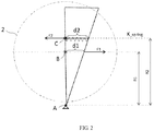
FIG. 2 is a schematic view showing a working model of an elastic member in the embodiment of the elevator guiding device shown inFIG. 1 . - First, it should be noted that the structural components, arrangements, characteristics, advantages and the like of the elevator guiding device and the elevator system comprising the elevator guiding device according to the present disclosure will be described below by way of example. However, all the descriptions should not be understood as limiting the present disclosure in any way. Herein, the technical term "connect (or connected, etc.)" covers situations where a component is directly connected to another component and/or indirectly connected to another component.
- In addition, for any single technical feature described or implied in the embodiments mentioned herein or any single technical feature shown or implied in individual drawings, the present disclosure still allows for any combination or deletion of these technical features (or equivalents thereof) without any technical obstacle. Therefore, it should be considered that these more embodiments according to the present disclosure are also within the scope of the description of this document. In addition, for the sake of brevity, general items already known to those skilled in the art will not be repeated herein.
-
FIG. 1 schematically shows the general composition of an embodiment of an elevator guiding device according to the present disclosure. The elevator guiding device is configured to be installed on an elevator car so as to guide the elevator car when the elevator car is running in an unbalanced loaded state along an elevator guiding rail, thereby preventing or reducing the occurrence of elevator car swaying, turning over and the like. In the embodiment shown inFIG. 1 , theelevator guiding device 100 may include abiased member 1, a guiding and contactingmember 2 and aconnection member 3, which are realized in structural forms of a pivoting arm, a roller and a bolt respectively. The elevator guidingdevice 100 is also generally called a "roll guide" in the industry, and the present disclosure will be described in detail below by means of this example. - Specifically, the
biased member 1 is arranged to have afirst end 11 and asecond end 12. For example, thesecond end 12 may be fixed to anelevator car 200 by any feasible connection means 7 such as a connection member 7 (such as bolts, screws, pins, etc.), welding and the like. For example, thesecond end 12 may be fixed to a suitable position such as a crosshead on the top of theelevator car 200, so that thesecond end 12 of thebiased member 1 can be fixed relative to theelevator car 200. In addition, the guiding and contactingmember 2 in the form of a roller may be installed between thefirst end 11 and thesecond end 12 of thebiased member 1. For example, the guiding and contactingmember 2 may be installed to thebiased member 1 by connection means such as a connection member 8 (such as bolts, screws, pins, etc.), welding and the like. - Reference is made to
FIG. 1 , in which the elevator car and the elevator guiding rail are represented merely schematically by usingblocks elevator car 200 is running along theelevator guiding rail 300, whether it is empty or currently loaded, it is possible that the total center of mass of the elevator car will deviate from the straight line where an elevator lifting rope is located, so the elevator car will be running in an unbalanced loaded state, which will result in a torque that causes the elevator car to deviate from the normal running trajectory. In this case, the guiding and contactingmember 2 installed on theelevator car 200 and in the form of a roller will contact theelevator guiding rail 300, thereby pressing against theelevator guiding rail 300 to prevent theelevator car 200 from turning over, swaying and the like unexpectedly. - As shown in
FIG. 1 , when the guiding and contactingmember 2 presses against theelevator guiding rail 300, theelevator guiding rail 300 will apply a force F to the guiding and contactingmember 2, which will drive thebiased member 1 to pivot around the fixed point of thesecond end 12 thereof on the elevator car 200 (that is, swing toward the right side in the figure around the position A shown inFIG. 1 ), so that anelastic member 4 in theconnection member 3 installed on thebiased member 1 is compressed accordingly, thereby providing a resistance force F' in the opposite direction to the above-mentioned force F. Through the synergy between the above two forces F and F', the unbalanced load adjustment process during the running of theelevator car 200 can be smoother and more stable, and theelevator car 200 can be prevented from swaying violently or even turning over. - With continued reference to
FIG. 1 , in addition to the above-mentionedelastic member 4, astop member 5 is also provided on theconnection member 3. Thestop member 5 can realize a more sufficient and reliable safety protection effect, etc. As compared with the prior art, the elastic member function and the stop member function are integrated into theconnection member 3 at the same time. This compact solution can not only provide reliable working performance, but also can make the elevator guiding device better adapt to the limited space in the elevator system (for example, as compared with the prior art, components such as thebiased member 1 with a smaller size can be used). Moreover, the number of components that need to be manufactured and assembled in the elevator guiding device can be effectively reduced, thereby helping reduce cost and improve product competitiveness. - As far as the
stop member 5 is concerned, as an example, when theelevator car 200 has a relatively serious unbalanced load condition when for example running along theelevator guiding rail 300, a relatively large force F will be generated between the guiding and contactingmember 2 of theelevator guiding device 100 and theelevator guiding rail 300 at this point, which will cause thebiased member 1 to produce a larger pivoting angle when biased. Once the above-mentioned pivoting angle is too large, it is very easy to cause obvious swaying of theelevator car 200, or even turning over, which will bring very unfavorable safety risks to personal safety, equipment, and property. In this case, through thestop member 5 provided on theconnection member 3, thebiased member 1 can be stopped once it reaches a preset position, thereby restricting the further movement of thebiased member 1, and therefore effectively realizing safety protection and other functions. It can be understood that the above-mentioned preset position may be flexibly set and adjusted according to various different requirements in practical applications, and more descriptions will be given below in conjunction with specific structural examples. - As an example, in an optional situation, the above-mentioned
elastic member 4 may be easily realized in many types of spring forms such as coil springs and disc springs. For example, a coil spring that meets actual application requirements can be directly sleeved over theconnection member 3 so as to be used as theelastic member 4. After theelastic member 4 has been assembled to theconnection member 3, it can provide a pre-tightening force between thebiased member 1 and theconnection member 3. Generally, theelastic member 4 may be made of any suitable metal material, such as steel, stainless steel, metal alloy and the like, so as to provide working performances that meet specific application requirements, such as sufficient strength, rigidity and/or corrosion resistance. - With combined reference to
FIGS. 1 and2 , although theconnection member 3 having theelastic member 4 is allowed to be installed at any suitable position on thebiased member 1 in the present disclosure, it would be advantageous if theconnection member 3 is arranged at thefirst end 11 or arranged at the position B of the guiding and contactingmember 2 on thebiased member 1. Specifically, if theelastic member 4 having an own initial stiffness K_spring is arranged at any position C on the biased member 1 (which is at a radius distance R2 from the pivot point A), after thebiased member 1 is pivoted by an angle under the action of force, the movement distance of theelastic member 4 at the position point C is d2, and the corresponding force is F2, that is, K spring = F2/d2; at the same time, the position point B is at a radius distance R1 from the pivot point A, the movement distance of theelastic member 4 at this position B is d1, and the corresponding force is F1; then when theelastic member 4 is arranged at the above position C, the achieved equivalent stiffness K_eq = F1/d1. In this way, the following relation (3) can be obtained from the following relations (1) and (2):


- From the above, it can be known that when R2≥R1, the actual equivalent stiffness K_eq of the
elastic member 4 will be a multiple of its own initial stiffness K spring, which means that when theconnection member 3 with theelastic member 4 is arranged in the above manner, the stiffness of theelastic member 4 can be effectively amplified, thereby providing a more optimized solution. For example, an elastic member with a relatively small stiffness can be selected under the premise of meeting application requirements, which is more advantageous for promoting the formation of a highly compact spatial layout. Regarding the above very advantageous optional arrangement of theconnection member 3 with theelastic member 4, it has been adopted in the embodiment shown inFIG. 1 . - In addition, for the above-mentioned
stop member 5, it can optionally be in the form of an annular sleeve, which is sleeved over theconnection member 3. As shown inFIG. 1 , by arranging the annular sleeve such that a preset distance S is maintained between one end of the annular sleeve and thebiased member 1, the purpose of enabling thebiased member 1 to be stopped at the preset position discussed above can be achieved. In addition, since theelastic member 4 is provided on theconnection member 3 together with thestop member 5, in order to avoid interference between them, an outer diameter of thestop member 5 in the form of an annular sleeve may be set to be smaller than an inner diameter of theelastic member 4 in the form of a coil spring. Such a structural design is not only simple and practical, but also enables a very easy installation, manufacturing and maintenance, and can effectively save the overall space occupied. As an optional situation, thestop member 5 can be made of elastic materials such as rubber, polyurethane, etc., which can realize good effects such as mitigating the impact of vibration and reducing weight. - As another example, the
stop member 5 is also allowed to be directly arranged on the outer surface of theconnection member 3 for example by means of casting, machining, welding and the like in the present disclosure. For example, a protrusion may be formed on at least a part of the outer surface of theconnection member 3 along the circumferential direction thereof, and the function of thestop member 5 described above is realized by such a protrusion. Similarly, the above-mentioned protrusion on theconnection member 3 will be configured not to interfere with theelastic member 4, and its end facing thebiased member 1 may also be arranged to be at a preset distance S from thebiased member 1. In the above optional situations, thestop member 5 can be made of a metal material, and the metal material may be the same as or different from the metal material used in theconnection member 3. - In practical applications, the
connection member 3 can be designed and manufactured separately according to the needs. Of course, a bolt may also be used directly, and one ormore nuts 6 may be installed at the end of the bolt to install theelastic member 4 and thestop member 5 on theconnection member 3. The respective ends of theelastic member 4 and thestop member 5 may both abut against thenuts 6, which is exemplarily shown inFIG. 1 . - It should be noted that in different applications, the elevator guiding device according to the present disclosure may be installed on the top, side and/or bottom of the elevator car. For example, the
biased member 1 in theelevator guiding device 100 may be directly installed on the top (for example, it is installed to the crosshead or other parts at the top), side (for example, it is installed to a side frame, etc.) and/or bottom (for example, it is installed to a bottom frame, etc.) of theelevator car 200; alternatively, theelevator guiding device 100 may also be provided with a bracket for installation on the top, side and/or bottom of theelevator car 200, and thebiased member 1 is installed to the bracket. - It should be noted that the present disclosure was described exemplarily only through the embodiment of the elevator guiding device in
FIG. 1 , in which the contact and force between the guiding and contactingmember 2 and theelevator guiding rail 300 are realized through a combination of the roller and the pivoting arm, and thebiased member 1 is pivoted to be biased away from its original position. However, it should be understood that the present disclosure is not limited to the specific examples described herein, and it can take other more structural forms. For example, thebiased member 1 and the guiding and contactingmember 2 may respectively take various feasible forms such as a slider and a friction plate fixed to the slider. - In view of the fact that the elevator guiding device according to the present disclosure has the above-mentioned technical advantages which are obviously superior to the prior art, it is very suitable to be applied to an elevator system so as to overcome the drawbacks and shortcomings existing in the prior art including those described above.
- In another technical solution according to the present disclosure, an elevator system is provided, in which one or more elevator guiding devices designed and provided according to the present disclosure may be equipped. For example, they can be arranged at any suitable position such as the top, side and/or bottom of the elevator car in the elevator system, so that when the elevator car is running in an unbalanced loaded state along the elevator guiding rail, the elevator guiding device can be used to timely and reliably take corresponding measures to prevent the elevator car from swaying, turning over, etc., so as to effectively improve the comfort and safety of taking the elevator.
- The elevator guiding device and the elevator system comprising the elevator guiding device according to the present disclosure have been elaborated above in detail by way of example only. These examples are merely used to illustrate the principles and embodiments of the present disclosure, rather than limiting the present disclosure. Various modifications and improvements can be made by those skilled in the art without departing from the spirit and scope of the present disclosure. Therefore, all equivalent technical solutions should fall within the scope of the present disclosure and be defined by the claims of the present disclosure.
Claims (10)
- An elevator guiding device, configured to be installed on an elevator car and comprising:a biased member; anda guiding and contacting member connected to the biased member and arranged to contact an elevator guiding rail when the elevator car is running in an unbalanced loaded state along the elevator guiding rail and cause the biased member to be biased, for guiding a running trajectory of the elevator car;wherein the elevator guiding device further comprises a connection member connected to the biased member and having an elastic member and a stop member, the elastic member is arranged to provide a pre-tightening force between the biased member and the connection member and provide a resistance force when the biased member is biased, and the stop member is arranged to stop the biased member when the biased member is biased to a preset position.
- The elevator guiding device according to claim 1, wherein the elastic member and the stop member are a spring and an annular sleeve sleeved over the connection member respectively, and the end of the annular sleeve facing the biasing part is spaced apart from the biased member by a preset distance.
- The elevator guiding device according to claim 2, wherein the spring is a coil spring, and an outer diameter of the annular sleeve is smaller than an inner diameter of the coil spring.
- The elevator guiding device according to claim 1, wherein the stop member is a protrusion provided along a circumferential direction on at least a part of an outer surface of the connection member, and the protrusion is configured not to interfere with the elastic member and the end of the protrusion facing the biased member is spaced apart from the biased member by a preset distance.
- The elevator guiding device according to any preceding claim, wherein the connection member is a bolt with a nut installed at an end, and the respective ends of the elastic member and the stop member facing the nut both abut against the nut.
- The elevator guiding device according to any preceding claim, wherein the biased member is installed on the top, side and/or bottom of the elevator car.
- The elevator guiding device according to any preceding claim, further comprising a bracket installed on the top, side and/or bottom of the elevator car, and wherein the biased member is installed on the bracket.
- The elevator guiding device according to any preceding claim, wherein the connection member and the elastic member are made of a metal material, and the stop member is made of an elastic material.
- The elevator guiding device according to any preceding claim, wherein the biased member has a first end, and a second end fixed relative to the elevator car, the guiding and contacting member is a roller rotatably installed on the biased member and located between the first end and the second end, the biased member is arranged to be pivotable around a fixed point of the second end on the elevator car after the roller contacts the elevator guiding rail, and the connection member is installed at the first end of the biased member.
- An elevator system, comprising:an elevator guiding rail;an elevator car running along the elevator guiding rail; andone or more elevator guiding devices according to any one of claims 1 to 9, which are installed on the elevator car.
Applications Claiming Priority (1)
| Application Number | Priority Date | Filing Date | Title |
|---|---|---|---|
| CN201922103765.9U CN211769621U (en) | 2019-11-29 | 2019-11-29 | Elevator guide and elevator system including the same |
Publications (1)
| Publication Number | Publication Date |
|---|---|
| EP3828118A1 true EP3828118A1 (en) | 2021-06-02 |
Family
ID=72961076
Family Applications (1)
| Application Number | Title | Priority Date | Filing Date |
|---|---|---|---|
| EP20210512.8A Withdrawn EP3828118A1 (en) | 2019-11-29 | 2020-11-30 | Elevator guiding device and elevator system comprising the same |
Country Status (3)
| Country | Link |
|---|---|
| US (1) | US20210163264A1 (en) |
| EP (1) | EP3828118A1 (en) |
| CN (1) | CN211769621U (en) |
Citations (3)
| Publication number | Priority date | Publication date | Assignee | Title |
|---|---|---|---|---|
| US3087583A (en) * | 1959-10-07 | 1963-04-30 | Otis Elevator Co | Extended roller guide for elevators |
| JPS5789560U (en) * | 1980-11-25 | 1982-06-02 | ||
| US5950771A (en) * | 1997-12-11 | 1999-09-14 | Otis Elevator Company | Roller guide friction damper |
-
2019
- 2019-11-29 CN CN201922103765.9U patent/CN211769621U/en not_active Expired - Fee Related
-
2020
- 2020-11-24 US US17/103,148 patent/US20210163264A1/en not_active Abandoned
- 2020-11-30 EP EP20210512.8A patent/EP3828118A1/en not_active Withdrawn
Patent Citations (3)
| Publication number | Priority date | Publication date | Assignee | Title |
|---|---|---|---|---|
| US3087583A (en) * | 1959-10-07 | 1963-04-30 | Otis Elevator Co | Extended roller guide for elevators |
| JPS5789560U (en) * | 1980-11-25 | 1982-06-02 | ||
| US5950771A (en) * | 1997-12-11 | 1999-09-14 | Otis Elevator Company | Roller guide friction damper |
Also Published As
| Publication number | Publication date |
|---|---|
| CN211769621U (en) | 2020-10-27 |
| US20210163264A1 (en) | 2021-06-03 |
Similar Documents
| Publication | Publication Date | Title |
|---|---|---|
| CN101112955B (en) | Elevator emergency braking device and elevator | |
| US5524548A (en) | Festoon brake system | |
| CN104583113A (en) | Elevator counterweight device | |
| US20220185627A1 (en) | Running system for elevator, and multi-car elevator running system | |
| EP3284710A1 (en) | Tie-down tensioning device for compensation sheave, compensation sheave and elevator | |
| JP4400956B2 (en) | Elevator safety device | |
| WO2018076781A1 (en) | Railway vehicle bogie and shaft end power generation assembly thereof | |
| US20150232301A1 (en) | Roller guide and manufacturing method for same | |
| US20210163264A1 (en) | Elevator guiding device and elevator system comprising the same | |
| AU2020367745B2 (en) | Safety assembly for off-highway truck | |
| JP2001002342A (en) | Emergency stop device for elevator | |
| CN111059140A (en) | An anti-jamming hinge structure | |
| CN214775893U (en) | a rail vehicle | |
| CN117962708A (en) | A bidirectional sliding energy-absorbing slide rail for car seats | |
| US11453571B2 (en) | Governor assembly for elevator system, elevator safety system and elevator system | |
| CN210133119U (en) | Rigidity-adjustable transverse elastic stop on anti-rolling torsion bar | |
| CN113800175A (en) | Guiding mechanism and stacker | |
| CN115107822B (en) | Sickle-shaped upper pull rod device | |
| WO2023050973A1 (en) | Leaf spring structure and suspension structure | |
| CN209921322U (en) | Bogies and trains having the same | |
| CN224014796U (en) | Crashproof pole and tray transfer chain | |
| WO2005068337A1 (en) | Elevator safety device | |
| CN223282437U (en) | Main and auxiliary plate spring without rolling lugs | |
| CN224076899U (en) | Elevator counterweight housing | |
| CN223906321U (en) | A mechanical blocking device for use in a floor-changing elevator |
Legal Events
| Date | Code | Title | Description |
|---|---|---|---|
| PUAI | Public reference made under article 153(3) epc to a published international application that has entered the european phase |
Free format text: ORIGINAL CODE: 0009012 |
|
| STAA | Information on the status of an ep patent application or granted ep patent |
Free format text: STATUS: THE APPLICATION HAS BEEN PUBLISHED |
|
| AK | Designated contracting states |
Kind code of ref document: A1 Designated state(s): AL AT BE BG CH CY CZ DE DK EE ES FI FR GB GR HR HU IE IS IT LI LT LU LV MC MK MT NL NO PL PT RO RS SE SI SK SM TR |
|
| STAA | Information on the status of an ep patent application or granted ep patent |
Free format text: STATUS: THE APPLICATION IS DEEMED TO BE WITHDRAWN |
|
| 18D | Application deemed to be withdrawn |
Effective date: 20211203 |