EP3828101A1 - A packaging device and method - Google Patents
A packaging device and method Download PDFInfo
- Publication number
- EP3828101A1 EP3828101A1 EP19212494.9A EP19212494A EP3828101A1 EP 3828101 A1 EP3828101 A1 EP 3828101A1 EP 19212494 A EP19212494 A EP 19212494A EP 3828101 A1 EP3828101 A1 EP 3828101A1
- Authority
- EP
- European Patent Office
- Prior art keywords
- support
- retainer
- packaging
- engagement surface
- product
- Prior art date
- Legal status (The legal status is an assumption and is not a legal conclusion. Google has not performed a legal analysis and makes no representation as to the accuracy of the status listed.)
- Withdrawn
Links
Images



Classifications
-
- B—PERFORMING OPERATIONS; TRANSPORTING
- B65—CONVEYING; PACKING; STORING; HANDLING THIN OR FILAMENTARY MATERIAL
- B65D—CONTAINERS FOR STORAGE OR TRANSPORT OF ARTICLES OR MATERIALS, e.g. BAGS, BARRELS, BOTTLES, BOXES, CANS, CARTONS, CRATES, DRUMS, JARS, TANKS, HOPPERS, FORWARDING CONTAINERS; ACCESSORIES, CLOSURES, OR FITTINGS THEREFOR; PACKAGING ELEMENTS; PACKAGES
- B65D73/00—Packages comprising articles attached to cards, sheets or webs
- B65D73/0064—Packages comprising articles attached to cards, sheets or webs the articles being supported by or suspended from a tag-like element
- B65D73/0071—Packages comprising articles attached to cards, sheets or webs the articles being supported by or suspended from a tag-like element the tag-like element being doubled-over to engage the upper part of the article
-
- B—PERFORMING OPERATIONS; TRANSPORTING
- B65—CONVEYING; PACKING; STORING; HANDLING THIN OR FILAMENTARY MATERIAL
- B65D—CONTAINERS FOR STORAGE OR TRANSPORT OF ARTICLES OR MATERIALS, e.g. BAGS, BARRELS, BOTTLES, BOXES, CANS, CARTONS, CRATES, DRUMS, JARS, TANKS, HOPPERS, FORWARDING CONTAINERS; ACCESSORIES, CLOSURES, OR FITTINGS THEREFOR; PACKAGING ELEMENTS; PACKAGES
- B65D73/00—Packages comprising articles attached to cards, sheets or webs
- B65D73/0064—Packages comprising articles attached to cards, sheets or webs the articles being supported by or suspended from a tag-like element
-
- B—PERFORMING OPERATIONS; TRANSPORTING
- B65—CONVEYING; PACKING; STORING; HANDLING THIN OR FILAMENTARY MATERIAL
- B65D—CONTAINERS FOR STORAGE OR TRANSPORT OF ARTICLES OR MATERIALS, e.g. BAGS, BARRELS, BOTTLES, BOXES, CANS, CARTONS, CRATES, DRUMS, JARS, TANKS, HOPPERS, FORWARDING CONTAINERS; ACCESSORIES, CLOSURES, OR FITTINGS THEREFOR; PACKAGING ELEMENTS; PACKAGES
- B65D73/00—Packages comprising articles attached to cards, sheets or webs
- B65D73/0078—Packages comprising articles attached to cards, sheets or webs the articles being retained or enclosed in a folded-over or doubled card
- B65D73/0085—Packages comprising articles attached to cards, sheets or webs the articles being retained or enclosed in a folded-over or doubled card within a window, hole or cut-out portion
-
- B—PERFORMING OPERATIONS; TRANSPORTING
- B65—CONVEYING; PACKING; STORING; HANDLING THIN OR FILAMENTARY MATERIAL
- B65D—CONTAINERS FOR STORAGE OR TRANSPORT OF ARTICLES OR MATERIALS, e.g. BAGS, BARRELS, BOTTLES, BOXES, CANS, CARTONS, CRATES, DRUMS, JARS, TANKS, HOPPERS, FORWARDING CONTAINERS; ACCESSORIES, CLOSURES, OR FITTINGS THEREFOR; PACKAGING ELEMENTS; PACKAGES
- B65D75/00—Packages comprising articles or materials partially or wholly enclosed in strips, sheets, blanks, tubes or webs of flexible sheet material, e.g. in folded wrappers
- B65D75/04—Articles or materials wholly enclosed in single sheets or wrapper blanks
- B65D75/20—Articles or materials wholly enclosed in single sheets or wrapper blanks in sheets or blanks doubled around contents and having their opposed free margins united, e.g. by pressure-sensitive adhesive, crimping, heat-sealing, or welding
- B65D75/22—Articles or materials wholly enclosed in single sheets or wrapper blanks in sheets or blanks doubled around contents and having their opposed free margins united, e.g. by pressure-sensitive adhesive, crimping, heat-sealing, or welding the sheet or blank being recessed to accommodate contents
-
- B—PERFORMING OPERATIONS; TRANSPORTING
- B65—CONVEYING; PACKING; STORING; HANDLING THIN OR FILAMENTARY MATERIAL
- B65D—CONTAINERS FOR STORAGE OR TRANSPORT OF ARTICLES OR MATERIALS, e.g. BAGS, BARRELS, BOTTLES, BOXES, CANS, CARTONS, CRATES, DRUMS, JARS, TANKS, HOPPERS, FORWARDING CONTAINERS; ACCESSORIES, CLOSURES, OR FITTINGS THEREFOR; PACKAGING ELEMENTS; PACKAGES
- B65D2575/00—Packages comprising articles or materials partially or wholly enclosed in strips, sheets, blanks, tubes or webs of flexible sheet material, e.g. in folded wrappers
- B65D2575/52—Details
- B65D2575/54—Cards, coupons, or other inserts or accessories
- B65D2575/56—Handles or other suspension means
- B65D2575/565—Handles or other suspension means means explicitly used for suspending
Definitions
- the present disclosure relates generally to the field of packaging, and in particular to a packaging device for a product to be marketed, promoted, and sold. More specifically, the present disclosure relates to a display packaging device for a handheld shaving device.
- the packaging for the product should clearly convey to potential consumers what the product is and where the product can be found.
- many products are displayed in single-use plastic packaging meant for specific, short-term usage before being recycled or disposed of and/or in packaging which uses excess materials.
- the usage of plastic and/or excess materials to display a product is both harmful to the environment and causes consumer frustration-as it is common for consumers to be conscious of the environment, unable to easily open the packaging, and unsure of where to find the product based upon the information presented on the packaging.
- the retainer may comprise an elastomer.
- the retainer may be connected to the support.
- the support may include a proximal end and a distal end and a securing member positioned on the first side of the support between the proximal and distal ends.
- the securing member may extend from the first edge to the second edge.
- a first indent may be defined at the first edge and a second indent may be defined at the second edge.
- the packaging may comprise a mounting segment positioned on and/or above the support.
- the support may include a bulge at or above the one or more indents.
- the engagement surface in the first position of the retainer the engagement surface cooperates with the second side of the support and in the second position of the retainer the engagement surface no longer cooperates with the second side of the support.
- the retainer may include a base affixed to the support and a band extending from the base.
- a method of making a packaging for a product comprises a step of providing a support having a first side and a second side and a first edge and a second edge, a step of defining one or more indents on the support, and a step of extending a retainer having an engagement surface from the support, the retainer having a first position wherein the engagement surface cooperates with the one or more indents to define a cavity between the retainer and the first side of the support and a second position wherein the engagement surface is withdrawn from the one or more indents, and the retainer is configured to engage the product within the cavity in the first position and disengage the product within the cavity in the second position.
- the method step of extending a retainer may include the retainer connecting to the support.
- the method may further comprise a step of including a securing member on the first side of the support.
- the method step of extending a retainer may include the engagement surface cooperating with the second side of the support in the first position and the engagement surface withdrawing from the second side of the support in the second position.
- the method step of extending a retainer may include the retainer comprising an elastomer.
- a method of engaging a product within a packaging comprises a step of providing a support having a first side and a second side and a first edge and a second edge, the support defining one or more indents, a step of extending a retainer having an engagement surface from the support, the retainer having a first position wherein the engagement surface cooperates with the one or more indents to define a cavity between the retainer and the first side of the support and a second position wherein the engagement surface no longer cooperates with the one or more indents, a step of positioning the product between the first side of the support and the retainer, and a step of transitioning the retainer from the second position to the first position, the retainer configured to hold the product within the cavity in the first position.
- the method step of extending the retainer may include the retainer connecting to the support.
- the method may further comprise a step of including a securing member on the first side of the support.
- the method step of extending a retainer may include the engagement surface cooperating with the second side of the support in the first position and the engagement surface no longer cooperating with the second side of the support in the second position.
- the method step of extending a retainer may include the retainer comprising an elastomer.
- the packaging may be configured to display the product while addressing one or more needs such as reducing the usage of harmful materials and/or excess materials, reducing difficulty in opening the packaging, and improving presentation of information on the packaging.
- first the terms “first,” “second,” etc. may be used herein to describe various elements, components, regions, layers, sections, and/or parameters, these elements, components, regions, layers, sections, and/or parameters should not be limited by these terms. These terms are only used to distinguish one element, component, region, layer, or section from another region, layer, or section. Thus, a first element, component, region, layer, or section discussed herein could be termed a second element, component, region, layer, or section without departing from the teachings of the present inventive subject matter.
- the packaging 10 is contemplated for use with a product (hereafter, "the product") 100, such as a handheld shaving device.
- the packaging 10 may include a support (wall) 20, a retainer 60, a securing member 80, and a mounting segment 90.
- the support 20 may be constructed from and/or as one sheet of die-cut material.
- the securing member 80 may also be constructed from and/or as one sheet of die-cut material.
- the mounting segment 90 may be constructed from and/or as one sheet of die-cut material.
- two or all three of the support 20, the securing member 80, and the mounting segment 90 may be constructed from and/or as one sheet of die-cut material to reduce the usage of harmful and/or excess materials.
- the material may be recycled paper, however, a person having ordinary skill in the art would understand that other materials, such as non-recycled paper, fiber, foil, cloth, corrugated cardboard, corrugated fiberboard, chipboard, paperboard, plastic, rubber, foam, and metal may be compatible with the packaging 10.
- the support 20 may include a first side 22 and a second side 24 extending laterally between a first edge 26a and an opposing second edge 26b and longitudinally between a proximal end 28 and a distal end 30. At the proximal end 30, the support 20 may define a first indent 32a and an opposing second indent 32b configured to cooperate with the retainer 60.
- the term "cooperate” as referred to herein should be understood to generally encompass interactions such as coupling, fastening, mating, affixing, engaging, and/or contacting to further a mechanical effect.
- Each of the first and second indent 32a, 32b may include a depth sufficient to hold the retainer 60 in a fixed position about the support 20.
- the first indent 32a may be defined at the first edge 26a and the second indent 32b may be defined at the second edge 26b.
- the first indent 32a may extend inwardly from the first edge 26a to a first shoulder 34a and the second indent 32b may extend inwardly from the second edge 26b to a second shoulder 34b.
- Each shoulder 34a, 34b is configured to impede the retainer 60 from withdrawing from each indent 32a, 32b.
- each shoulder 34a, 34b may transition further inwardly to a first indent engagement surface 36a and a second indent engagement surface 36b configured to engage the retainer 60.
- the second side 24 of the support 20 may also include a support engagement surface 38 configured to engage the retainer 60. It is contemplated that each shoulder 34a, 34b may also be considered to be part of the first and second indent engagement surfaces 36a, 36b and configured to engage the retainer 60.
- the first and second indents 32a, 32b may include an arcuate contour, however, a person having ordinary skill in the art would appreciate that other contours such as an angled contour may be used for the first and second indents 32a, 32b.
- the second side 24 of the support 20 may define a third indent 33 at the proximal end 28 configured to cooperate with the retainer 60 and have a structure and functionality similar to the first and second indents 32a, 32b.
- the third indent 33 may be included by the packaging 10 as an alternative to the first and/or second indents 32a, 32b or in combination with the first and/or second indents 32a, 32b.
- the first side 22 of the support 20 may include the securing member 80 between the proximal and distal ends 28, 30.
- the securing member 80 may extend from and connect to the first and second edges 26a, 26b.
- the securing member 80 is configured to surround and fix the product 100 in position against the first side 22 of the support 20.
- the securing member 80 may be constructed from the same material as the support 20. Further, the securing member 80 and the support 20 may be constructed from and/or as one sheet of die-cut material or from and/or as two sheets of die-cut material.
- the securing member 80 may also function as a banner and include noticeable informational text and/or graphics relating to the product 100 to improve the presentation of information related to the product 100.
- the securing member 80 may be polygonal, but a person having ordinary skill in the art would appreciate that other shapes such as an oval, wavy, circular or any other shape such that the securing member 80 may be compatible with the packaging 10.
- the retainer 60 may include a base 62 extending to a band 64.
- the base 62 may be configured to connect the band 64 to the support 20 and be shaped as and/or function as a cradle or support to hold the product 100 against the support 20.
- the band may have a substantially rectangular cross-sectional shape which may reduce curling of the band within itself.
- the base 62 and the band 64 may be configured to be elastically deformed so as to be passed from the first side 22 of the support 20 to the second side 24 of the support 20, thereby reducing any difficulty experienced by a user in opening the packaging 10 (see Figure 5 ).
- the base 62 and the band 64 may be constructed of an elastomeric material such as caoutchouc (natural) rubber, however, a person having ordinary skill in the art would understand that other flexible and/or polymeric materials such as synthetic rubber, nitrile rubber, silicone rubber, vinyl rubber, and/or neoprene may be compatible with the packaging 10.
- the band 64 may include a retainer engagement surface 66 (see Figures 2B and 3 ) configured to engage the first and second indent engagement surfaces 36a, 36b and the support engagement surface 38.
- the retainer 60 may be configured to transition between a first position and a second position. In the first position, the band 64 may be within the first and second indents 32a, 32b and/or on the second side 24 of the support 20, while the base 62 may remain positioned about the first side 22 of the support 20. In the first position, the retainer engagement surface 66 may cooperate with and/or engage the first and second indent engagement surfaces 36a, 36b and/or the support engagement surface 38.
- the band 64 may no longer cooperate with and/or withdraw from within the first and second indents 32a, 32b and/or from the second side 24 of the support 20.
- the retainer engagement surface 66 may no longer cooperate with and/or be withdrawn from the first and second indent engagement surfaces 36a, 36b and/or the support engagement surface 66.
- a cavity 68 (see Figure 3 ) may be defined between the first side 22 of the support 20, the base 62, and the band 64.
- the base 62 and the band 64 may engage and/or suspend the product 100 within the cavity 68.
- the base 62 and the band 64 may apply a retention force on the product 100 and press the product 100 against the first side 22 of the support 20 within the cavity 68.
- the support 20 may include a bulge 40 at the proximal end 28 to accommodate the product 100 within the cavity 68.
- the base 62 and the band 64 may no longer engage and/or suspend the product 100 within the cavity 68 and may allow the product 100 to be released and removed from the cavity 68 and thus the packaging 10.
- the securing member 80 may be torn away from the support 20 (see Figure 2B ) to further enable removal of the product 100 from the packaging 10.
- a user may grasp the band 64 of the retainer 60 between their fingers and proceed to pull the band 64 outwardly and away from the second side 24 of the support 20 (see Figure 5 ). Pulling the band 64 outwardly and away from the second side 24 of the support 20 may disengage the retainer engagement surface 66 from the support engagement surface 38. The user may then rotate the band 64 toward and over the proximal end 28 of the support 20, from the second side 24 of the support 20 to the first side 22 of the support 20 (see Figure 4 , wherein it should be understood that the product is not shown in cross-section).
- Rotating the band 64 and the retainer engagement surface 66 from the second side 24 of the support 20 to the first side 22 of the support 20 may withdraw retainer engagement surface 66 from the first and second indent engagement surfaces 36a, 36b and the band 64 from the first and second indents 32a, 32b.
- the retainer 60 may be in the second position and allow for the product 100 to be released and removed from the cavity 68 and the packaging 10. Reversing this process may transition the retainer 60 from the second position to the first position.
- the packaging may include the mounting segment 90 at the proximal end 28 of the packaging 10.
- the mounting segment 90 may function to hang and display the packaging 10 and the product 100 on a display structure (not shown).
- the mounting segment 90 may be substantially flat and define an aperture 92 for receiving the display structure.
- the aperture 92 may include one or more notches 94 at an upper portion for positioning the mounting segment 90 upon the display structure.
- the mounting segment 90 may be constructed from the same material as the support 20. Further, the mounting segment 90 and the support 20 may be constructed from and/or as one sheet of die-cut material or be constructed from and/or as two sheets of die-cut material and affixed to each other.
- the material may be folded at an intersection 96 (see Figures 3 and 4 ) between the mounting segment 90 and the proximal end 28 of the support 20.
- the base 62 of the retainer 60 may bond to the mounting segment 90 and the support 20 at the intersection 96 between the mounting segment 90 and the support 20.
- the retainer 60 may be thermoglued to the mounting segment 90 and the support 20, however, a person having ordinary skill in the art would appreciate that other methods and materials may be used to bonding and/or affixing the retainer 60 to the mounting segment 90 and the support 20.
- the packaging 10 may include a near-field communication (NFC) chip (not shown) embedded in or attached to the securing member 80 or the support 20 to enable communication with an electronic device exterior to the packaging 10 and improve the presentation of information related to the product 100.
- NFC near-field communication
Landscapes
- Engineering & Computer Science (AREA)
- Mechanical Engineering (AREA)
- Packages (AREA)
- Buffer Packaging (AREA)
- Basic Packing Technique (AREA)
Abstract
Description
- The present disclosure relates generally to the field of packaging, and in particular to a packaging device for a product to be marketed, promoted, and sold. More specifically, the present disclosure relates to a display packaging device for a handheld shaving device.
- When marketing, promoting, and selling a product, the packaging for the product should clearly convey to potential consumers what the product is and where the product can be found. Currently, many products are displayed in single-use plastic packaging meant for specific, short-term usage before being recycled or disposed of and/or in packaging which uses excess materials. The usage of plastic and/or excess materials to display a product is both harmful to the environment and causes consumer frustration-as it is common for consumers to be conscious of the environment, unable to easily open the packaging, and unsure of where to find the product based upon the information presented on the packaging.
- It is desirable to provide an improved packaging in a manner that fulfills one or more of the needs described above.
- According to aspects of the present disclosure, a packaging (hereafter, "the packaging") for a product comprises a support and a retainer, the support has a first side and a second side and a first edge and a second edge, the support defines one or more indents, the retainer extends from the support and includes an engagement surface, the retainer configured to adopt a first position wherein the engagement surface cooperates with the one or more indents to define a cavity between the retainer and the first side of the support and a second position wherein the engagement surface no longer cooperates with the one or more indents, and the retainer is configured to hold the product within the cavity in the first position and release the product within the cavity in the second position.
- According to aspects of the present disclosure, the retainer may comprise an elastomer.
- According to aspects of the present disclosure, the retainer may be connected to the support.
- According to aspects of the present disclosure, the support may include a proximal end and a distal end and a securing member positioned on the first side of the support between the proximal and distal ends.
- According to aspects of the present disclosure, the securing member may extend from the first edge to the second edge.
- According to aspects of the present disclosure, a first indent may be defined at the first edge and a second indent may be defined at the second edge.
- According to aspects of the present disclosure, the packaging may comprise a mounting segment positioned on and/or above the support.
- According to aspects of the present disclosure, the support may include a bulge at or above the one or more indents.
- According to aspects of the present disclosure, in the first position of the retainer the engagement surface cooperates with the second side of the support and in the second position of the retainer the engagement surface no longer cooperates with the second side of the support.
- According to aspects of the present disclosure, the retainer may include a base affixed to the support and a band extending from the base.
- According to aspects of the present disclosure, a method of making a packaging for a product is provided. The method comprises a step of providing a support having a first side and a second side and a first edge and a second edge, a step of defining one or more indents on the support, and a step of extending a retainer having an engagement surface from the support, the retainer having a first position wherein the engagement surface cooperates with the one or more indents to define a cavity between the retainer and the first side of the support and a second position wherein the engagement surface is withdrawn from the one or more indents, and the retainer is configured to engage the product within the cavity in the first position and disengage the product within the cavity in the second position.
- According to aspects of the present disclosure, the method step of extending a retainer may include the retainer connecting to the support.
- According to aspects of the present disclosure, the method may further comprise a step of including a securing member on the first side of the support.
- According to aspects of the present disclosure, the method step of extending a retainer may include the engagement surface cooperating with the second side of the support in the first position and the engagement surface withdrawing from the second side of the support in the second position.
- According to aspects of the present disclosure, the method step of extending a retainer may include the retainer comprising an elastomer.
- According to aspects of the disclosure, a method of engaging a product within a packaging is provided. The method comprises a step of providing a support having a first side and a second side and a first edge and a second edge, the support defining one or more indents, a step of extending a retainer having an engagement surface from the support, the retainer having a first position wherein the engagement surface cooperates with the one or more indents to define a cavity between the retainer and the first side of the support and a second position wherein the engagement surface no longer cooperates with the one or more indents, a step of positioning the product between the first side of the support and the retainer, and a step of transitioning the retainer from the second position to the first position, the retainer configured to hold the product within the cavity in the first position.
- According to aspects of the present disclosure, the method step of extending the retainer may include the retainer connecting to the support.
- According to aspects of the present disclosure, the method may further comprise a step of including a securing member on the first side of the support.
- According to aspects of the present disclosure, the method step of extending a retainer may include the engagement surface cooperating with the second side of the support in the first position and the engagement surface no longer cooperating with the second side of the support in the second position.
- According to aspects of the present disclosure, the method step of extending a retainer may include the retainer comprising an elastomer.
- In the manner described and according to aspects illustrated herein, the packaging may be configured to display the product while addressing one or more needs such as reducing the usage of harmful materials and/or excess materials, reducing difficulty in opening the packaging, and improving presentation of information on the packaging.
- Aspects of an embodiment will be described in reference to the drawings, where like numerals reflect like elements:
-
Figure 1A is a front perspective view of the packaging according to aspects of the disclosure; -
Figure 1B is a rear perspective view of the packaging ofFigure 1A ; -
Figure 2A is a front perspective view of the packaging ofFigure 1A , illustrating a retainer of the packaging in a second position; -
Figure 2B is a front perspective view of the packaging ofFigure 1A , illustrating a securing member of the packaging being torn away from the packaging; -
Figure 3 is a side view of the packaging ofFigure 1A ; -
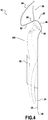
Figure 4 is a side cross-sectional view of the packaging ofFigure 1A , taken along line IV shown inFigure 2A ; and -
Figure 5 is a rear perspective view of the packaging ofFigure 1A , illustrating the retainer of the packaging transitioning between a first position and the second position. - An embodiment of the packaging according to aspects of the disclosure will now be described with reference to
Figures 1A-5 , wherein like numerals represent like parts, and will generally be referred to by thereference numeral 10. Although thepackaging 10 is described with reference to specific examples, it should be understood that modifications and changes may be made to these examples without going beyond the general scope as defined by the claims. In particular, individual characteristics of the various embodiments shown and/or mentioned herein may be combined in additional embodiments. Consequently, the description and the drawings should be considered in a sense that is illustrative rather than restrictive. The Figures, which are not necessarily to scale, depict illustrative aspects and are not intended to limit the scope of the disclosure. The illustrative aspects depicted are intended only as exemplary. - The term "exemplary" is used in the sense of "example," rather than "ideal." While aspects of the disclosure are amenable to various modifications and alternative forms, specifics thereof have been shown by way of example in the drawings and will be described in detail. It should be understood, however, that the intention is not to limit aspects of the disclosure to the particular embodiment(s) described. On the contrary, the intention of this disclosure is to cover all modifications, equivalents, and alternatives falling within the scope of the disclosure.
- Various materials, methods of construction and methods of fastening will be discussed in the context of the disclosed embodiment(s). Those skilled in the art will recognize known substitutes for the materials, construction methods, and fastening methods, all of which are contemplated as compatible with the disclosed embodiment(s) and are intended to be encompassed by the appended claims.
- As used in this disclosure and the appended claims, the singular forms "a," "an," and "the" include plural referents unless the content clearly dictates otherwise. As used in this disclosure and the appended claims, the term "or" is generally employed in its sense including "and/or" unless the content clearly dictates otherwise.
- Throughout the description, including the claims, the terms "comprising a," "including a," and "having a" should be understood as being synonymous with "comprising one or more," "including one or more," and "having one or more" unless otherwise stated. In addition, any range set forth in the description, including the claims should be understood as including its end value(s) unless otherwise stated. Specific values for described elements should be understood to be within accepted manufacturing or industry tolerances known to one of skill in the art, and any use of the terms "substantially," "approximately," and "generally" should be understood to mean falling within such accepted tolerances.
- When an element or feature is referred to herein as being "on," "engaged to," "connected to," or "coupled to" another element or feature, it may be directly on, engaged, connected, or coupled to the other element or feature, or intervening elements or features may be present. In contrast, when an element or feature is referred to as being "directly on," "directly engaged to," "directly connected to," or "directly coupled to" another element or feature, there may be no intervening elements or features present. Other words used to describe the relationship between elements or features should be interpreted in a like fashion (e.g., "between" versus "directly between," "adjacent" versus "directly adjacent," etc.).
- Spatially relative terms, such as "top," "bottom," "middle," "inner," "outer," "beneath," "below," "lower," "above," "upper," and the like, may be used herein for ease of description to describe one element or feature's relationship to another element(s) or feature(s) as illustrated in the drawings. Spatially relative terms may be intended to encompass different orientations of a device in use or operation in addition to the orientation depicted in the drawings. For example, if the device in the drawings is turned over, elements described as "below" or "beneath" other elements or features would then be oriented "above" the other elements or features. Thus, the example term "below" can encompass both an orientation of above and below. The device may be otherwise oriented (rotated 90 degrees or at other orientations) and the spatially relative descriptors used herein interpreted accordingly.
- Although the terms "first," "second," etc. may be used herein to describe various elements, components, regions, layers, sections, and/or parameters, these elements, components, regions, layers, sections, and/or parameters should not be limited by these terms. These terms are only used to distinguish one element, component, region, layer, or section from another region, layer, or section. Thus, a first element, component, region, layer, or section discussed herein could be termed a second element, component, region, layer, or section without departing from the teachings of the present inventive subject matter.
- The
packaging 10 is contemplated for use with a product (hereafter, "the product") 100, such as a handheld shaving device. As shown inFigures 1A and 1B , thepackaging 10 may include a support (wall) 20, aretainer 60, a securingmember 80, and a mountingsegment 90. Thesupport 20 may be constructed from and/or as one sheet of die-cut material. The securingmember 80 may also be constructed from and/or as one sheet of die-cut material. Additionally, the mountingsegment 90 may be constructed from and/or as one sheet of die-cut material. However, it is contemplated that two or all three of thesupport 20, the securingmember 80, and the mountingsegment 90 may be constructed from and/or as one sheet of die-cut material to reduce the usage of harmful and/or excess materials. In the disclosed embodiment, the material may be recycled paper, however, a person having ordinary skill in the art would understand that other materials, such as non-recycled paper, fiber, foil, cloth, corrugated cardboard, corrugated fiberboard, chipboard, paperboard, plastic, rubber, foam, and metal may be compatible with thepackaging 10. - As illustrated by
Figures 1A-2B , thesupport 20 may include afirst side 22 and asecond side 24 extending laterally between afirst edge 26a and an opposingsecond edge 26b and longitudinally between aproximal end 28 and adistal end 30. At theproximal end 30, thesupport 20 may define afirst indent 32a and an opposingsecond indent 32b configured to cooperate with theretainer 60. The term "cooperate" as referred to herein should be understood to generally encompass interactions such as coupling, fastening, mating, affixing, engaging, and/or contacting to further a mechanical effect. Each of the first andsecond indent retainer 60 in a fixed position about thesupport 20. Thefirst indent 32a may be defined at thefirst edge 26a and thesecond indent 32b may be defined at thesecond edge 26b. Thefirst indent 32a may extend inwardly from thefirst edge 26a to afirst shoulder 34a and thesecond indent 32b may extend inwardly from thesecond edge 26b to asecond shoulder 34b. Eachshoulder retainer 60 from withdrawing from eachindent shoulder indent engagement surface 36a and a secondindent engagement surface 36b configured to engage theretainer 60. Thesecond side 24 of thesupport 20 may also include asupport engagement surface 38 configured to engage theretainer 60. It is contemplated that eachshoulder indent engagement surfaces retainer 60. In the disclosed embodiment, the first andsecond indents second indents second side 24 of thesupport 20 may define athird indent 33 at theproximal end 28 configured to cooperate with theretainer 60 and have a structure and functionality similar to the first andsecond indents third indent 33 may be included by thepackaging 10 as an alternative to the first and/orsecond indents second indents - Referring to
Figures 1A-2B , thefirst side 22 of thesupport 20 may include the securingmember 80 between the proximal and distal ends 28, 30. The securingmember 80 may extend from and connect to the first andsecond edges member 80 is configured to surround and fix theproduct 100 in position against thefirst side 22 of thesupport 20. The securingmember 80 may be constructed from the same material as thesupport 20. Further, the securingmember 80 and thesupport 20 may be constructed from and/or as one sheet of die-cut material or from and/or as two sheets of die-cut material. The securingmember 80 may also function as a banner and include noticeable informational text and/or graphics relating to theproduct 100 to improve the presentation of information related to theproduct 100. In the disclosed embodiment, the securingmember 80 may be polygonal, but a person having ordinary skill in the art would appreciate that other shapes such as an oval, wavy, circular or any other shape such that the securingmember 80 may be compatible with thepackaging 10. - As shown in
Figures 1A-4 , theretainer 60 may include a base 62 extending to aband 64. The base 62 may be configured to connect theband 64 to thesupport 20 and be shaped as and/or function as a cradle or support to hold theproduct 100 against thesupport 20. In circumstances, the band may have a substantially rectangular cross-sectional shape which may reduce curling of the band within itself. Thebase 62 and theband 64 may be configured to be elastically deformed so as to be passed from thefirst side 22 of thesupport 20 to thesecond side 24 of thesupport 20, thereby reducing any difficulty experienced by a user in opening the packaging 10 (seeFigure 5 ). In the disclosed embodiment, thebase 62 and theband 64 may be constructed of an elastomeric material such as caoutchouc (natural) rubber, however, a person having ordinary skill in the art would understand that other flexible and/or polymeric materials such as synthetic rubber, nitrile rubber, silicone rubber, vinyl rubber, and/or neoprene may be compatible with thepackaging 10. - The
band 64 may include a retainer engagement surface 66 (seeFigures 2B and3 ) configured to engage the first and secondindent engagement surfaces support engagement surface 38. Theretainer 60 may be configured to transition between a first position and a second position. In the first position, theband 64 may be within the first andsecond indents second side 24 of thesupport 20, while thebase 62 may remain positioned about thefirst side 22 of thesupport 20. In the first position, theretainer engagement surface 66 may cooperate with and/or engage the first and secondindent engagement surfaces support engagement surface 38. In the second position, theband 64 may no longer cooperate with and/or withdraw from within the first andsecond indents second side 24 of thesupport 20. In the second position, theretainer engagement surface 66 may no longer cooperate with and/or be withdrawn from the first and secondindent engagement surfaces support engagement surface 66. In the first position, a cavity 68 (seeFigure 3 ) may be defined between thefirst side 22 of thesupport 20, thebase 62, and theband 64. In the first position, thebase 62 and theband 64 may engage and/or suspend theproduct 100 within thecavity 68. In the first position, thebase 62 and theband 64 may apply a retention force on theproduct 100 and press theproduct 100 against thefirst side 22 of thesupport 20 within thecavity 68. To this effect, thesupport 20 may include abulge 40 at theproximal end 28 to accommodate theproduct 100 within thecavity 68. In the second position, thebase 62 and theband 64 may no longer engage and/or suspend theproduct 100 within thecavity 68 and may allow theproduct 100 to be released and removed from thecavity 68 and thus thepackaging 10. The securingmember 80 may be torn away from the support 20 (seeFigure 2B ) to further enable removal of theproduct 100 from thepackaging 10. - As illustrated by
Figures 1-2B and4-5 , to transition theretainer 60 from the first position to the second position, a user may grasp theband 64 of theretainer 60 between their fingers and proceed to pull theband 64 outwardly and away from thesecond side 24 of the support 20 (seeFigure 5 ). Pulling theband 64 outwardly and away from thesecond side 24 of thesupport 20 may disengage theretainer engagement surface 66 from thesupport engagement surface 38. The user may then rotate theband 64 toward and over theproximal end 28 of thesupport 20, from thesecond side 24 of thesupport 20 to thefirst side 22 of the support 20 (seeFigure 4 , wherein it should be understood that the product is not shown in cross-section). Rotating theband 64 and theretainer engagement surface 66 from thesecond side 24 of thesupport 20 to thefirst side 22 of thesupport 20 may withdrawretainer engagement surface 66 from the first and secondindent engagement surfaces band 64 from the first andsecond indents retainer engagement surface 66 and theband 64 have been withdrawn from the first and secondindent engagement surfaces second indents retainer 60 may be in the second position and allow for theproduct 100 to be released and removed from thecavity 68 and thepackaging 10. Reversing this process may transition theretainer 60 from the second position to the first position. - Referring to
Figure 1 , the packaging may include the mountingsegment 90 at theproximal end 28 of thepackaging 10. The mountingsegment 90 may function to hang and display thepackaging 10 and theproduct 100 on a display structure (not shown). In the disclosed embodiment, the mountingsegment 90 may be substantially flat and define anaperture 92 for receiving the display structure. Theaperture 92 may include one ormore notches 94 at an upper portion for positioning the mountingsegment 90 upon the display structure. The mountingsegment 90 may be constructed from the same material as thesupport 20. Further, the mountingsegment 90 and thesupport 20 may be constructed from and/or as one sheet of die-cut material or be constructed from and/or as two sheets of die-cut material and affixed to each other. In an embodiment where the mountingsegment 90 and thesupport 20 are constructed from and/or as one sheet of die-cut material, the material may be folded at an intersection 96 (seeFigures 3 and4 ) between the mountingsegment 90 and theproximal end 28 of thesupport 20. Thebase 62 of theretainer 60 may bond to the mountingsegment 90 and thesupport 20 at theintersection 96 between the mountingsegment 90 and thesupport 20. In the disclosed embodiment, theretainer 60 may be thermoglued to the mountingsegment 90 and thesupport 20, however, a person having ordinary skill in the art would appreciate that other methods and materials may be used to bonding and/or affixing theretainer 60 to the mountingsegment 90 and thesupport 20. - The
packaging 10 may include a near-field communication (NFC) chip (not shown) embedded in or attached to the securingmember 80 or thesupport 20 to enable communication with an electronic device exterior to thepackaging 10 and improve the presentation of information related to theproduct 100. - Although the present disclosure herein has been described with reference to particular embodiments, it is to be understood that these embodiments are merely illustrative of the principles and applications of the present disclosure.
- It is intended that the specification and examples be considered as exemplary only, with a true scope of the disclosure being indicated by the following claims.
- Additionally, all of the disclosed features of an apparatus may be transposed, alone or in combination, to a method and vice versa.
Claims (15)
- A packaging (10) for a product (100) comprising:a support (20) having a first side (22) and a second side (24) and a first edge (26a) and a second edge (26b), said support (20) defining one or more indents (32a, 32b, 33);a retainer (60) extending from the support (20) and including an engagement surface (66), said retainer (60) configured to adopt a first position wherein the engagement surface (66) cooperates with the one or more indents (32a, 32b, 33) to define a cavity (68) between the retainer (60) and the first side (22) of the support (20) and a second position wherein the engagement surface (66) no longer cooperates with the one or more indents (32a, 32b, 33), said retainer (60) configured to hold the product (100) within the cavity (68) in the first position and release the product (100) from the cavity (68) in the second position.
- The packaging (10) of claim 1, wherein the retainer (60) comprises an elastomer.
- The packaging (10) of any one of claims 1-2, wherein the retainer (60) is connected to the support (20).
- The packaging (10) of any of claims 1-3, wherein the support (20) includes a proximal end (28) and a distal end (30) and a securing member (80) positioned on the first side (22) of the support (20) between the proximal and distal ends (28, 30).
- The packaging (10) of claim 4, wherein the securing member (80) extends from the first edge (26a) to the second edge (26b).
- The packaging (10) of any of claims 1-5, wherein a first indent (32a) is defined at the first edge (26a) and a second indent (32b) is defined at the second edge (26b).
- The packaging (10) of any of claims 1-6, wherein the packaging (10) comprises a mounting segment (90) positioned on and/or above the support (20).
- The packaging (10) of any of claims 1-7, wherein the support (20) includes a bulge (40) at or above the one or more indents (32a, 32b, 33).
- The packaging (10) of any of claims 1-8, wherein in the first position of the retainer (60) the engagement surface (66) cooperates with the second side (24) of the support (20) and in the second position of the retainer (60) the engagement surface (66) no longer cooperates with the second side (24) of the support (20).
- The packaging (10) of any of claims 1-9, wherein the retainer (60) includes a base (62) affixed to the support (20) and a band (64) extending from the base (62).
- A method of engaging a product (100) within a packaging (10) comprising:providing a support (20) having a first side (22) and a second side (24) and a first edge (26a) and a second edge (26b), said support defining one or more indents (32a, 32b, 33);extending a retainer (60) having an engagement surface (66) from the support (20), said retainer (60) having a first position wherein the engagement surface (66) cooperates with the one or more indents (32a, 32b, 33) to define a cavity (68) between the retainer (60) and the first side (22) of the support (20) and a second position wherein the engagement surface (66) no longer cooperates with the one or more indents (32a, 32b, 33);positioning the product (100) between the first side (22) of the support (20) and the retainer (60);
transitioning the retainer (60) from the second position to the first position, said retainer (60) configured to hold the product (100) within the cavity (68) in the first position. - The method of claim 11, wherein the step of extending the retainer (60) includes the retainer (60) connecting to the support (20).
- The method of any of claims 11-12, further comprising a step of including a securing member (80) on the first side (22) of the support (20).
- The method of any of claims 11-13, wherein the step of extending a retainer (60) includes the engagement surface (66) cooperating with the second side (24) of the support (20) in the first position and the engagement surface (66) no longer cooperating with the second side (24) of the support (20) in the second position.
- The method of any of claims 11-14, wherein the step of extending a retainer (60) includes the retainer (60) comprising an elastomer.
Priority Applications (5)
| Application Number | Priority Date | Filing Date | Title |
|---|---|---|---|
| EP19212494.9A EP3828101A1 (en) | 2019-11-29 | 2019-11-29 | A packaging device and method |
| MX2022006296A MX2022006296A (en) | 2019-11-29 | 2020-11-27 | A packaging device and method. |
| PCT/EP2020/083730 WO2021105426A1 (en) | 2019-11-29 | 2020-11-27 | A packaging device and method |
| US17/755,129 US11912485B2 (en) | 2019-11-29 | 2020-11-27 | Packaging device and method |
| BR112022010151A BR112022010151A2 (en) | 2019-11-29 | 2020-11-27 | DEVICE AND PACKAGING METHOD |
Applications Claiming Priority (1)
| Application Number | Priority Date | Filing Date | Title |
|---|---|---|---|
| EP19212494.9A EP3828101A1 (en) | 2019-11-29 | 2019-11-29 | A packaging device and method |
Publications (1)
| Publication Number | Publication Date |
|---|---|
| EP3828101A1 true EP3828101A1 (en) | 2021-06-02 |
Family
ID=68732900
Family Applications (1)
| Application Number | Title | Priority Date | Filing Date |
|---|---|---|---|
| EP19212494.9A Withdrawn EP3828101A1 (en) | 2019-11-29 | 2019-11-29 | A packaging device and method |
Country Status (5)
| Country | Link |
|---|---|
| US (1) | US11912485B2 (en) |
| EP (1) | EP3828101A1 (en) |
| BR (1) | BR112022010151A2 (en) |
| MX (1) | MX2022006296A (en) |
| WO (1) | WO2021105426A1 (en) |
Citations (7)
| Publication number | Priority date | Publication date | Assignee | Title |
|---|---|---|---|---|
| GB2218368A (en) * | 1988-05-11 | 1989-11-15 | Henry Thomas Mill | A razor holder |
| DE9205046U1 (en) * | 1992-04-10 | 1992-06-17 | Pemas Auto- und Zweiradzubehör GmbH, 8000 München | Packaging for an article comprising an elongated rod-shaped section |
| US20010047948A1 (en) * | 2000-06-05 | 2001-12-06 | Cummings Eric G. | Paintbrush protector |
| US20040226842A1 (en) * | 2003-05-14 | 2004-11-18 | O'toole Lawrence | Rack packaging for hairbrushes |
| DE102007014895A1 (en) * | 2006-03-27 | 2007-10-18 | Herm. Friedr. Künne Gmbh & Co. | Packing material for a profiled rail has a suspension device linked to a stay to hold the profiled rail with a pin plugged in the suspension device |
| US20160016712A1 (en) * | 2014-07-21 | 2016-01-21 | Hong Ann Tool Industries Co., Ltd. | Tool Holder Capable of Preventing From Being Dismantled |
| US9371153B1 (en) * | 2015-03-04 | 2016-06-21 | Modern Twist, Inc. | Shaped elastomeric container with integrated leak resistant seal |
Family Cites Families (12)
| Publication number | Priority date | Publication date | Assignee | Title |
|---|---|---|---|---|
| US4140244A (en) | 1978-02-03 | 1979-02-20 | Clabby Merlyn L | Disposable razor dispenser |
| US4888868A (en) | 1988-01-21 | 1989-12-26 | Pritchard Kevin M | Disposable razor assembly with detachable packet containing shaving-associated material |
| US5090570A (en) * | 1990-07-09 | 1992-02-25 | Todd Alvin E | Package for a small fragile item |
| FR2722173B1 (en) * | 1994-07-06 | 1996-10-04 | Dubost Colas Pradel Ets | PRESENTATION CARD FOR SHOP ITEMS, ESPECIALLY COVERED |
| DE19501395A1 (en) | 1995-01-18 | 1996-08-01 | Henkel Kgaa | Product card |
| US6520328B2 (en) | 2001-02-28 | 2003-02-18 | Warner-Lambert Company | Retail razor display package with razor stand |
| US6857521B2 (en) | 2002-07-13 | 2005-02-22 | Plasticos Y Alambres, S.A. | Container and retaining device for packaging and unwinding coiled welding wire |
| JP4068450B2 (en) * | 2002-12-27 | 2008-03-26 | 松下電器産業株式会社 | Product package |
| JP2007161344A (en) | 2005-12-14 | 2007-06-28 | Lupo:Kk | Rubber band fixing type packing box |
| US20120103362A1 (en) | 2010-10-14 | 2012-05-03 | David Nowacek | Shaving product dispenser container with mirror |
| DE202011000751U1 (en) * | 2011-03-31 | 2011-05-26 | wolfcraft GmbH, 56746 | Housing, in particular packaging housing for a tool |
| US10583954B2 (en) | 2018-03-16 | 2020-03-10 | Bic Violex S.A. | Packaging for a shaver and related methods of use |
-
2019
- 2019-11-29 EP EP19212494.9A patent/EP3828101A1/en not_active Withdrawn
-
2020
- 2020-11-27 BR BR112022010151A patent/BR112022010151A2/en active Search and Examination
- 2020-11-27 WO PCT/EP2020/083730 patent/WO2021105426A1/en not_active Ceased
- 2020-11-27 US US17/755,129 patent/US11912485B2/en active Active
- 2020-11-27 MX MX2022006296A patent/MX2022006296A/en unknown
Patent Citations (8)
| Publication number | Priority date | Publication date | Assignee | Title |
|---|---|---|---|---|
| GB2218368A (en) * | 1988-05-11 | 1989-11-15 | Henry Thomas Mill | A razor holder |
| DE9205046U1 (en) * | 1992-04-10 | 1992-06-17 | Pemas Auto- und Zweiradzubehör GmbH, 8000 München | Packaging for an article comprising an elongated rod-shaped section |
| US20010047948A1 (en) * | 2000-06-05 | 2001-12-06 | Cummings Eric G. | Paintbrush protector |
| US20040226842A1 (en) * | 2003-05-14 | 2004-11-18 | O'toole Lawrence | Rack packaging for hairbrushes |
| DE102007014895A1 (en) * | 2006-03-27 | 2007-10-18 | Herm. Friedr. Künne Gmbh & Co. | Packing material for a profiled rail has a suspension device linked to a stay to hold the profiled rail with a pin plugged in the suspension device |
| DE102007014895B4 (en) * | 2006-03-27 | 2015-02-26 | Küberit Profile Systems GmbH & Co. KG | Packaging for a profile rail |
| US20160016712A1 (en) * | 2014-07-21 | 2016-01-21 | Hong Ann Tool Industries Co., Ltd. | Tool Holder Capable of Preventing From Being Dismantled |
| US9371153B1 (en) * | 2015-03-04 | 2016-06-21 | Modern Twist, Inc. | Shaped elastomeric container with integrated leak resistant seal |
Also Published As
| Publication number | Publication date |
|---|---|
| WO2021105426A1 (en) | 2021-06-03 |
| MX2022006296A (en) | 2022-06-08 |
| BR112022010151A2 (en) | 2022-08-09 |
| US20220380103A1 (en) | 2022-12-01 |
| US11912485B2 (en) | 2024-02-27 |
Similar Documents
| Publication | Publication Date | Title |
|---|---|---|
| KR101229070B1 (en) | Three dimensional face mask and method of manufacture thereof | |
| CA2726372A1 (en) | Thermal protector sleeve for hot drink cup | |
| KR20200033906A (en) | Retention packaging assembly | |
| US9355578B2 (en) | Container label and related methods | |
| US10752401B2 (en) | Lifting handle | |
| US11912485B2 (en) | Packaging device and method | |
| JP2008239251A (en) | Wrap film device with flap | |
| US7484652B2 (en) | Disposable lid and handle combination for container | |
| JP5453588B2 (en) | Container with neck label | |
| JP2015030480A (en) | Product holder | |
| CA2657814A1 (en) | Product packaging with tear strip | |
| EP2557046A1 (en) | Packing case | |
| JP6636811B2 (en) | Film roll storage device | |
| CN216003598U (en) | Packing box | |
| CN110921046B (en) | Packaging box for digital products and using method | |
| JP3140986U (en) | Sheet-shaped pull-top opening device and container | |
| JP4413081B2 (en) | Hand seal | |
| JP3126654U (en) | Cardboard box carrying handle | |
| JP6010351B2 (en) | Method for manufacturing wrap film storage box and wrap film storage box | |
| EP3006361A1 (en) | Container | |
| KR200464901Y1 (en) | Packaging case used pet bottles | |
| CN211618388U (en) | Corrugated packaging carton easy to close and open | |
| JP5797801B2 (en) | Packaging film | |
| JP6385022B1 (en) | Telescopic band | |
| CN110921045B (en) | Digital product packaging box and using method |
Legal Events
| Date | Code | Title | Description |
|---|---|---|---|
| PUAI | Public reference made under article 153(3) epc to a published international application that has entered the european phase |
Free format text: ORIGINAL CODE: 0009012 |
|
| STAA | Information on the status of an ep patent application or granted ep patent |
Free format text: STATUS: THE APPLICATION HAS BEEN PUBLISHED |
|
| AK | Designated contracting states |
Kind code of ref document: A1 Designated state(s): AL AT BE BG CH CY CZ DE DK EE ES FI FR GB GR HR HU IE IS IT LI LT LU LV MC MK MT NL NO PL PT RO RS SE SI SK SM TR |
|
| STAA | Information on the status of an ep patent application or granted ep patent |
Free format text: STATUS: REQUEST FOR EXAMINATION WAS MADE |
|
| 17P | Request for examination filed |
Effective date: 20211202 |
|
| RBV | Designated contracting states (corrected) |
Designated state(s): AL AT BE BG CH CY CZ DE DK EE ES FI FR GB GR HR HU IE IS IT LI LT LU LV MC MK MT NL NO PL PT RO RS SE SI SK SM TR |
|
| RAP3 | Party data changed (applicant data changed or rights of an application transferred) |
Owner name: BIC VIOLEX SINGLE MEMBER S.A. |
|
| STAA | Information on the status of an ep patent application or granted ep patent |
Free format text: STATUS: EXAMINATION IS IN PROGRESS |
|
| 17Q | First examination report despatched |
Effective date: 20230330 |
|
| GRAP | Despatch of communication of intention to grant a patent |
Free format text: ORIGINAL CODE: EPIDOSNIGR1 |
|
| STAA | Information on the status of an ep patent application or granted ep patent |
Free format text: STATUS: GRANT OF PATENT IS INTENDED |
|
| INTG | Intention to grant announced |
Effective date: 20240912 |
|
| STAA | Information on the status of an ep patent application or granted ep patent |
Free format text: STATUS: THE APPLICATION IS DEEMED TO BE WITHDRAWN |
|
| 18D | Application deemed to be withdrawn |
Effective date: 20250114 |