EP3828071A1 - Interface for electric assist bicycle - Google Patents
Interface for electric assist bicycle Download PDFInfo
- Publication number
- EP3828071A1 EP3828071A1 EP20210032.7A EP20210032A EP3828071A1 EP 3828071 A1 EP3828071 A1 EP 3828071A1 EP 20210032 A EP20210032 A EP 20210032A EP 3828071 A1 EP3828071 A1 EP 3828071A1
- Authority
- EP
- European Patent Office
- Prior art keywords
- interface
- bicycle
- component
- bike
- processor
- Prior art date
- Legal status (The legal status is an assumption and is not a legal conclusion. Google has not performed a legal analysis and makes no representation as to the accuracy of the status listed.)
- Pending
Links
Images





Classifications
-
- B—PERFORMING OPERATIONS; TRANSPORTING
- B62—LAND VEHICLES FOR TRAVELLING OTHERWISE THAN ON RAILS
- B62M—RIDER PROPULSION OF WHEELED VEHICLES OR SLEDGES; POWERED PROPULSION OF SLEDGES OR SINGLE-TRACK CYCLES; TRANSMISSIONS SPECIALLY ADAPTED FOR SUCH VEHICLES
- B62M6/00—Rider propulsion of wheeled vehicles with additional source of power, e.g. combustion engine or electric motor
- B62M6/40—Rider propelled cycles with auxiliary electric motor
- B62M6/45—Control or actuating devices therefor
- B62M6/50—Control or actuating devices therefor characterised by detectors or sensors, or arrangement thereof
-
- B—PERFORMING OPERATIONS; TRANSPORTING
- B62—LAND VEHICLES FOR TRAVELLING OTHERWISE THAN ON RAILS
- B62M—RIDER PROPULSION OF WHEELED VEHICLES OR SLEDGES; POWERED PROPULSION OF SLEDGES OR SINGLE-TRACK CYCLES; TRANSMISSIONS SPECIALLY ADAPTED FOR SUCH VEHICLES
- B62M6/00—Rider propulsion of wheeled vehicles with additional source of power, e.g. combustion engine or electric motor
- B62M6/10—Rider propelled cycles with auxiliary combustion engine
- B62M6/15—Control or actuating devices therefor
-
- B—PERFORMING OPERATIONS; TRANSPORTING
- B62—LAND VEHICLES FOR TRAVELLING OTHERWISE THAN ON RAILS
- B62J—CYCLE SADDLES OR SEATS; AUXILIARY DEVICES OR ACCESSORIES SPECIALLY ADAPTED TO CYCLES AND NOT OTHERWISE PROVIDED FOR, e.g. ARTICLE CARRIERS OR CYCLE PROTECTORS
- B62J99/00—Subject matter not provided for in other groups of this subclass
-
- B—PERFORMING OPERATIONS; TRANSPORTING
- B60—VEHICLES IN GENERAL
- B60L—PROPULSION OF ELECTRICALLY-PROPELLED VEHICLES; SUPPLYING ELECTRIC POWER FOR AUXILIARY EQUIPMENT OF ELECTRICALLY-PROPELLED VEHICLES; ELECTRODYNAMIC BRAKE SYSTEMS FOR VEHICLES IN GENERAL; MAGNETIC SUSPENSION OR LEVITATION FOR VEHICLES; MONITORING OPERATING VARIABLES OF ELECTRICALLY-PROPELLED VEHICLES; ELECTRIC SAFETY DEVICES FOR ELECTRICALLY-PROPELLED VEHICLES
- B60L15/00—Methods, circuits, or devices for controlling the traction-motor speed of electrically-propelled vehicles
- B60L15/20—Methods, circuits, or devices for controlling the traction-motor speed of electrically-propelled vehicles for control of the vehicle or its driving motor to achieve a desired performance, e.g. speed, torque, programmed variation of speed
-
- B—PERFORMING OPERATIONS; TRANSPORTING
- B62—LAND VEHICLES FOR TRAVELLING OTHERWISE THAN ON RAILS
- B62J—CYCLE SADDLES OR SEATS; AUXILIARY DEVICES OR ACCESSORIES SPECIALLY ADAPTED TO CYCLES AND NOT OTHERWISE PROVIDED FOR, e.g. ARTICLE CARRIERS OR CYCLE PROTECTORS
- B62J1/00—Saddles or other seats for cycles; Arrangement thereof; Component parts
- B62J1/08—Frames for saddles; Connections between saddle frames and seat pillars; Seat pillars
-
- B—PERFORMING OPERATIONS; TRANSPORTING
- B62—LAND VEHICLES FOR TRAVELLING OTHERWISE THAN ON RAILS
- B62J—CYCLE SADDLES OR SEATS; AUXILIARY DEVICES OR ACCESSORIES SPECIALLY ADAPTED TO CYCLES AND NOT OTHERWISE PROVIDED FOR, e.g. ARTICLE CARRIERS OR CYCLE PROTECTORS
- B62J43/00—Arrangements of batteries
- B62J43/10—Arrangements of batteries for propulsion
- B62J43/13—Arrangements of batteries for propulsion on rider-propelled cycles with additional electric propulsion
-
- B—PERFORMING OPERATIONS; TRANSPORTING
- B62—LAND VEHICLES FOR TRAVELLING OTHERWISE THAN ON RAILS
- B62J—CYCLE SADDLES OR SEATS; AUXILIARY DEVICES OR ACCESSORIES SPECIALLY ADAPTED TO CYCLES AND NOT OTHERWISE PROVIDED FOR, e.g. ARTICLE CARRIERS OR CYCLE PROTECTORS
- B62J43/00—Arrangements of batteries
- B62J43/30—Arrangements of batteries for providing power to equipment other than for propulsion
-
- B—PERFORMING OPERATIONS; TRANSPORTING
- B62—LAND VEHICLES FOR TRAVELLING OTHERWISE THAN ON RAILS
- B62J—CYCLE SADDLES OR SEATS; AUXILIARY DEVICES OR ACCESSORIES SPECIALLY ADAPTED TO CYCLES AND NOT OTHERWISE PROVIDED FOR, e.g. ARTICLE CARRIERS OR CYCLE PROTECTORS
- B62J45/00—Electrical equipment arrangements specially adapted for use as accessories on cycles, not otherwise provided for
- B62J45/20—Cycle computers as cycle accessories
-
- B—PERFORMING OPERATIONS; TRANSPORTING
- B62—LAND VEHICLES FOR TRAVELLING OTHERWISE THAN ON RAILS
- B62J—CYCLE SADDLES OR SEATS; AUXILIARY DEVICES OR ACCESSORIES SPECIALLY ADAPTED TO CYCLES AND NOT OTHERWISE PROVIDED FOR, e.g. ARTICLE CARRIERS OR CYCLE PROTECTORS
- B62J45/00—Electrical equipment arrangements specially adapted for use as accessories on cycles, not otherwise provided for
- B62J45/40—Sensor arrangements; Mounting thereof
- B62J45/41—Sensor arrangements; Mounting thereof characterised by the type of sensor
- B62J45/412—Speed sensors
-
- B—PERFORMING OPERATIONS; TRANSPORTING
- B62—LAND VEHICLES FOR TRAVELLING OTHERWISE THAN ON RAILS
- B62J—CYCLE SADDLES OR SEATS; AUXILIARY DEVICES OR ACCESSORIES SPECIALLY ADAPTED TO CYCLES AND NOT OTHERWISE PROVIDED FOR, e.g. ARTICLE CARRIERS OR CYCLE PROTECTORS
- B62J50/00—Arrangements specially adapted for use on cycles not provided for in main groups B62J1/00 - B62J45/00
- B62J50/20—Information-providing devices
- B62J50/21—Information-providing devices intended to provide information to rider or passenger
- B62J50/22—Information-providing devices intended to provide information to rider or passenger electronic, e.g. displays
-
- B—PERFORMING OPERATIONS; TRANSPORTING
- B62—LAND VEHICLES FOR TRAVELLING OTHERWISE THAN ON RAILS
- B62J—CYCLE SADDLES OR SEATS; AUXILIARY DEVICES OR ACCESSORIES SPECIALLY ADAPTED TO CYCLES AND NOT OTHERWISE PROVIDED FOR, e.g. ARTICLE CARRIERS OR CYCLE PROTECTORS
- B62J50/00—Arrangements specially adapted for use on cycles not provided for in main groups B62J1/00 - B62J45/00
- B62J50/20—Information-providing devices
- B62J50/21—Information-providing devices intended to provide information to rider or passenger
- B62J50/225—Mounting arrangements therefor
-
- B—PERFORMING OPERATIONS; TRANSPORTING
- B62—LAND VEHICLES FOR TRAVELLING OTHERWISE THAN ON RAILS
- B62K—CYCLES; CYCLE FRAMES; CYCLE STEERING DEVICES; RIDER-OPERATED TERMINAL CONTROLS SPECIALLY ADAPTED FOR CYCLES; CYCLE AXLE SUSPENSIONS; CYCLE SIDECARS, FORECARS, OR THE LIKE
- B62K11/00—Motorcycles, engine-assisted cycles or motor scooters with one or two wheels
- B62K11/14—Handlebar constructions, or arrangements of controls thereon, specially adapted thereto
-
- B—PERFORMING OPERATIONS; TRANSPORTING
- B62—LAND VEHICLES FOR TRAVELLING OTHERWISE THAN ON RAILS
- B62K—CYCLES; CYCLE FRAMES; CYCLE STEERING DEVICES; RIDER-OPERATED TERMINAL CONTROLS SPECIALLY ADAPTED FOR CYCLES; CYCLE AXLE SUSPENSIONS; CYCLE SIDECARS, FORECARS, OR THE LIKE
- B62K19/00—Cycle frames
- B62K19/30—Frame parts shaped to receive other cycle parts or accessories
-
- B—PERFORMING OPERATIONS; TRANSPORTING
- B62—LAND VEHICLES FOR TRAVELLING OTHERWISE THAN ON RAILS
- B62K—CYCLES; CYCLE FRAMES; CYCLE STEERING DEVICES; RIDER-OPERATED TERMINAL CONTROLS SPECIALLY ADAPTED FOR CYCLES; CYCLE AXLE SUSPENSIONS; CYCLE SIDECARS, FORECARS, OR THE LIKE
- B62K25/00—Axle suspensions
- B62K25/04—Axle suspensions for mounting axles resiliently on cycle frame or fork
-
- B—PERFORMING OPERATIONS; TRANSPORTING
- B62—LAND VEHICLES FOR TRAVELLING OTHERWISE THAN ON RAILS
- B62M—RIDER PROPULSION OF WHEELED VEHICLES OR SLEDGES; POWERED PROPULSION OF SLEDGES OR SINGLE-TRACK CYCLES; TRANSMISSIONS SPECIALLY ADAPTED FOR SUCH VEHICLES
- B62M25/00—Actuators for gearing speed-change mechanisms specially adapted for cycles
-
- B—PERFORMING OPERATIONS; TRANSPORTING
- B62—LAND VEHICLES FOR TRAVELLING OTHERWISE THAN ON RAILS
- B62M—RIDER PROPULSION OF WHEELED VEHICLES OR SLEDGES; POWERED PROPULSION OF SLEDGES OR SINGLE-TRACK CYCLES; TRANSMISSIONS SPECIALLY ADAPTED FOR SUCH VEHICLES
- B62M9/00—Transmissions characterised by use of an endless chain, belt, or the like
- B62M9/04—Transmissions characterised by use of an endless chain, belt, or the like of changeable ratio
-
- G—PHYSICS
- G06—COMPUTING OR CALCULATING; COUNTING
- G06F—ELECTRIC DIGITAL DATA PROCESSING
- G06F3/00—Input arrangements for transferring data to be processed into a form capable of being handled by the computer; Output arrangements for transferring data from processing unit to output unit, e.g. interface arrangements
- G06F3/01—Input arrangements or combined input and output arrangements for interaction between user and computer
- G06F3/02—Input arrangements using manually operated switches, e.g. using keyboards or dials
-
- G—PHYSICS
- G08—SIGNALLING
- G08C—TRANSMISSION SYSTEMS FOR MEASURED VALUES, CONTROL OR SIMILAR SIGNALS
- G08C17/00—Arrangements for transmitting signals characterised by the use of a wireless electrical link
- G08C17/02—Arrangements for transmitting signals characterised by the use of a wireless electrical link using a radio link
-
- G—PHYSICS
- G09—EDUCATION; CRYPTOGRAPHY; DISPLAY; ADVERTISING; SEALS
- G09G—ARRANGEMENTS OR CIRCUITS FOR CONTROL OF INDICATING DEVICES USING STATIC MEANS TO PRESENT VARIABLE INFORMATION
- G09G5/00—Control arrangements or circuits for visual indicators common to cathode-ray tube indicators and other visual indicators
- G09G5/10—Intensity circuits
-
- G—PHYSICS
- G09—EDUCATION; CRYPTOGRAPHY; DISPLAY; ADVERTISING; SEALS
- G09G—ARRANGEMENTS OR CIRCUITS FOR CONTROL OF INDICATING DEVICES USING STATIC MEANS TO PRESENT VARIABLE INFORMATION
- G09G5/00—Control arrangements or circuits for visual indicators common to cathode-ray tube indicators and other visual indicators
- G09G5/36—Control arrangements or circuits for visual indicators common to cathode-ray tube indicators and other visual indicators characterised by the display of a graphic pattern, e.g. using an all-points-addressable [APA] memory
- G09G5/37—Details of the operation on graphic patterns
-
- B—PERFORMING OPERATIONS; TRANSPORTING
- B60—VEHICLES IN GENERAL
- B60L—PROPULSION OF ELECTRICALLY-PROPELLED VEHICLES; SUPPLYING ELECTRIC POWER FOR AUXILIARY EQUIPMENT OF ELECTRICALLY-PROPELLED VEHICLES; ELECTRODYNAMIC BRAKE SYSTEMS FOR VEHICLES IN GENERAL; MAGNETIC SUSPENSION OR LEVITATION FOR VEHICLES; MONITORING OPERATING VARIABLES OF ELECTRICALLY-PROPELLED VEHICLES; ELECTRIC SAFETY DEVICES FOR ELECTRICALLY-PROPELLED VEHICLES
- B60L2200/00—Type of vehicles
- B60L2200/46—Vehicles with auxiliary ad-on propulsions, e.g. add-on electric motor kits for bicycles
-
- G—PHYSICS
- G09—EDUCATION; CRYPTOGRAPHY; DISPLAY; ADVERTISING; SEALS
- G09G—ARRANGEMENTS OR CIRCUITS FOR CONTROL OF INDICATING DEVICES USING STATIC MEANS TO PRESENT VARIABLE INFORMATION
- G09G2320/00—Control of display operating conditions
- G09G2320/06—Adjustment of display parameters
- G09G2320/0626—Adjustment of display parameters for control of overall brightness
-
- G—PHYSICS
- G09—EDUCATION; CRYPTOGRAPHY; DISPLAY; ADVERTISING; SEALS
- G09G—ARRANGEMENTS OR CIRCUITS FOR CONTROL OF INDICATING DEVICES USING STATIC MEANS TO PRESENT VARIABLE INFORMATION
- G09G2354/00—Aspects of interface with display user
-
- G—PHYSICS
- G09—EDUCATION; CRYPTOGRAPHY; DISPLAY; ADVERTISING; SEALS
- G09G—ARRANGEMENTS OR CIRCUITS FOR CONTROL OF INDICATING DEVICES USING STATIC MEANS TO PRESENT VARIABLE INFORMATION
- G09G2360/00—Aspects of the architecture of display systems
- G09G2360/14—Detecting light within display terminals, e.g. using a single or a plurality of photosensors
- G09G2360/144—Detecting light within display terminals, e.g. using a single or a plurality of photosensors the light being ambient light
-
- Y—GENERAL TAGGING OF NEW TECHNOLOGICAL DEVELOPMENTS; GENERAL TAGGING OF CROSS-SECTIONAL TECHNOLOGIES SPANNING OVER SEVERAL SECTIONS OF THE IPC; TECHNICAL SUBJECTS COVERED BY FORMER USPC CROSS-REFERENCE ART COLLECTIONS [XRACs] AND DIGESTS
- Y02—TECHNOLOGIES OR APPLICATIONS FOR MITIGATION OR ADAPTATION AGAINST CLIMATE CHANGE
- Y02T—CLIMATE CHANGE MITIGATION TECHNOLOGIES RELATED TO TRANSPORTATION
- Y02T10/00—Road transport of goods or passengers
- Y02T10/60—Other road transportation technologies with climate change mitigation effect
- Y02T10/72—Electric energy management in electromobility
Definitions
- the present disclosure is generally directed to a human machine interface (HMI) and, more particularly, to an HMI for an e-bike.
- HMI human machine interface
- Electric drive systems are used to assist a rider of a bicycle to ride longer and/or faster.
- An assist motor and a battery are added to the bicycle to accomplish this as an electric bike (e.g., an e-bike).
- One type of e-bike requires pedaling to start the assist motor.
- a pedal force or pedal rotation is measured, and a controller of the e-bike controls the assist motor based on the measured pedal force or the measured pedal rotation.
- the assist motor may be positioned on a frame of the e-bike, and the assist motor may provide motor assist at cranks of the e-bike.
- the motor assist may be provided based on the measured pedal force or the measured pedal rotation, such that a combined power of a power generated by the assist motor and a drive power input generated by the rider goes through a geared drivetrain of the e-bike.
- an interface in one example, includes a housing attachable to a first frame part of a bicycle, and a processor supported by the housing.
- the interface also includes a first communication interface and a second communication interface in communication with the processor.
- the first communication interface is a wired communication interface
- the second communication interface is a wireless communication interface.
- the interface includes an input in communication with the processor and supported by the housing. The input is configured to generate a first control signal based on a first user input.
- the processor is configured to receive a second control signal via the second communication interface.
- the second control signal is generated by a control device attached to a second frame part of the bicycle based on a second user input.
- the processor is also configured to control a component of the bicycle via the first communication interface based on the first control signal and the received second control signal.
- the first frame part is a top tube of the bicycle
- the second frame part is a handlebar of the bicycle.
- the input is a physical user interface.
- the processor is further configured to receive data representing characteristics related to the component of the bicycle from the component of the bicycle via the first communication interface.
- the interface further includes an output in communication with the processor.
- the output is configured to output a representation of at least one of the characteristics related to the component of the bicycle.
- the output is a display supported by the housing.
- the display is configured to display the representation of the at least one characteristic related to the component of the bicycle.
- the interface further includes an ambient light sensor configured to determine an amount of ambient light in an environment in which the interface is disposed.
- the processor is configured to change a brightness of the display based on the determined amount of ambient light in the environment.
- the component of the bicycle is an e-bike motor system.
- the e-bike motor system includes a drive motor and a battery.
- the characteristics related to the e-bike motor system includes battery power, a time to complete a charge, a charge rate, a percent state of charge, power level, speed, cadence, a system warning or error message, or any combination thereof.
- the component of the bicycle is an e-bike motor system.
- the e-bike motor system includes a drive motor and a battery.
- the processor is configured to be powered by the battery of the e-bike motor system via the first communication interface.
- the e-bike motor system further includes a drive motor.
- the processor is configured to control the drive motor of the e-bike motor system via the first communication interface based on the first control signal or the received second control signal.
- control of the drive motor of the e-bike motor system based on the first control signal or the received second control signal comprises the processor being configured to turn the drive motor on or off, or change a power level of the drive motor.
- control device attached to the second frame part of the bicycle is a wireless handlebar mounted e-bike control interface, a wireless handlebar mounted shifter or seat post control interface, a wireless handlebar mounted e-bike assist level control interface, or a wireless handlebar mounted automatic shifting control interface.
- the component is a first component.
- the processor is further configured to receive data from a second component of the bicycle, transmit data to the second component of the bicycle, or receive and transmit data to the second component of the bicycle.
- the interface further includes a third communication interface in communication with the processor.
- the third communication interface is a wireless communication interface.
- the processor is configured to receive the second control signal via the second communication interface using a first wireless communication protocol.
- the processor is configured to receive data from the second component of the bicycle, transmit data to the second component of the bicycle, or receive and transmit data to the second component of the bicycle via the third communication interface using a second wireless communication protocol.
- the second wireless communication protocol is different than the first wireless communication protocol.
- the second component of the bicycle is a wirelessly controlled derailleur, a wirelessly controlled front suspension fork, or a rear suspension shock.
- the component is a first component
- the first component receives a timed digital pulse from a speed sensor
- the speed sensor communicates to the processor via the first communication interface.
- the processor is configured to communicate with a device outside of the bicycle via the second communication interface or a third communication interface.
- the third communication interface is different than the second communication interface and is a wireless communication interface.
- the processor is further configured to determine whether a signal from the device outside of the bicycle is received and allow operation of the component of the bicycle when the signal is received from the device outside of the bicycle.
- the device outside of the bicycle is a passive wireless electronic device or a mobile device.
- a bicycle communication apparatus for an e-bike includes a housing attachable to a top tube of a frame of a bicycle, a processor supported by the housing, and a wired communication interface in communication with the processor.
- the wired communication interface is wiredly connectable to an e-bike motor system.
- the e-bike motor system includes a drive motor.
- the bicycle communication apparatus further includes a wireless communication interface in communication with the processor.
- the wireless communication interface is wirelessly connectable to a control device attached to a handlebar of the bicycle.
- the bicycle communication apparatus includes an input supported by the housing and in communication with the processor. The input is configured to generate a first control signal based on a first user input.
- the processor is configured to receive a second control signal from the control device attached to the handlebar of the bicycle via the wireless communication interface.
- the second control signal is for the e-bike motor system and is generated by the control device based on a second user input.
- the processor is further configured to control the drive motor of the e-bike motor system via the wired communication interface based on the first control signal or the received second control signal.
- the wireless communication interface is a first wireless communication interface.
- the bicycle communication apparatus further includes a second wireless communication interface.
- the second wireless communication interface is in communication with the processor and is wirelessly connected to a movable component of the bicycle.
- the movable component of the bicycle is movable relative to the bicycle communication apparatus.
- the processor is in communication with the control device attached to the handlebar of the bicycle and the movable component of the bicycle using different wireless protocols, respectively.
- an e-bike system for a bicycle includes an e-bike motor system including a drive motor and a battery.
- the e-bike system also includes a bicycle communication apparatus.
- the bicycle communication apparatus includes a housing attachable to a frame of the bicycle, a processor supported by the housing, and a wired communication interface in communication with the processor.
- the wired communication interface is wiredly connected to the e-bike motor system.
- the bicycle communication apparatus also includes a wireless communication interface in communication with the processor.
- the wireless communication interface is wirelessly connectable to a control device attached to a handlebar of the bicycle.
- the bicycle communication apparatus includes an input supported by the housing and in communication with the processor. The input is configured to generate a first control signal based on a first user input.
- the processor of the bicycle communication apparatus is configured to receive a second control signal from the control device attached to the handlebar of the bicycle via the wireless communication interface.
- the second control signal is generated by the control device based on a second user input.
- the processor of the bicycle communication apparatus is further configured to control the drive motor of the e-bike motor system via the wired communication interface based on the first control signal or the received second control signal.
- a number of peripheral inputs are provided for control of an assist motor of an e-bike.
- Inputs such as, for example, power on/off, a power assist level, a battery level, and/or other inputs may be provided.
- characteristics of the assist motor and the battery of the e-bike are to be displayed while the rider rides the e-bike. Characteristics such as, for example, battery level, a power setting, a gear indication, a speed, a cadence, a power, and/or other characteristics may be displayed to the rider.
- the rider is to be able to control the peripheral inputs and view the displayed characteristics while riding the e-bike (e.g., via a display).
- the peripheral inputs and the display may be located on the handlebar and may be a wired connection to a control system of the e-bike.
- the peripheral inputs and the display also compete for space if installed on the handlebar, as a full-featured mapping computer may also be installed on the handlebar.
- bicycle components are to be integrated into operation of the e-bike (e.g., the assist motor).
- the other bicycle components include, for example, electrically controlled deraille, gear hubs, suspension devices, height adjust seat posts, lights, audible devices, power meters, computing devices, other sensors such as cadence sensors, wheel speed sensors, inclination sensors, wind speed sensors, direction sensors, altitude sensors, seat pressure sensors, post height sensors, pedal force sensors, and/or other components.
- These bicycle components may be controlled wirelessly, as wires are a major source of failure on bicycle components (e.g., off-road mountain bicycles).
- the wireless bicycle components may be controlled by corresponding wireless controls located on the handlebar.
- the e-bike interface (e.g., a bicycle communication apparatus (BCA)) of the present embodiments is a hybrid wired/wireless e-bike control system that integrates wireless bicycle components into operation of an e-bike.
- the e-bike interface provides a frame-mounted control and display that is wired to, for example, the assist motor and the battery, and provides a wireless communication bridge between wireless bicycle components and corresponding wireless controls located on the handlebar.
- the e-bike interface may be configured to turn part of an e-bike system (e.g., the assist motor) on and off.
- the e-bike interface is further configured to display characteristics of the e-bike system such as, for example, battery power, gear indication, power level, speed, cadence, system warnings or error messages, and/or other information.
- a rider is able to change the power level for the e-bike system (e.g., the power level for the assist motor) via the e-bike interface.
- the e-bike interface acts as a communication bridge between a controller area network bus (CANBUS) of the wired e-bike system and a number of wireless components integrated into the function of the e-bike system.
- CANBUS controller area network bus
- wireless components include wireless handlebar-mounted walk to boost buttons, a wirelessly controlled rear derailleur, wireless handlebar-mounted shifter and seat post control units, a wirelessly controlled front suspension fork and/or a wirelessly controlled rear suspension shock, a wireless handlebar-mounted assist level button, and/or a wireless handlebar-mounted automatic shifting setting button.
- FIG. 1 generally illustrates one example of a bicycle 100 on which the disclosed interface may be implemented.
- the bicycle 100 may be a mountain bicycle.
- the bicycle 100 may be an e-bike.
- the bicycle 100 has a frame 102, a handlebar 104 near a front end of the frame 102, and a seat or saddle 106 for supporting a rider over a top of the frame 102.
- the bicycle 100 also has a first or front wheel 108 carried by a front fork 110 of the frame 102 and supporting the front end of the frame 102.
- the bicycle 100 also has a second or rear wheel 112 supporting a rear end of the frame 102.
- the rear end of the frame 102 may be connected to a rear suspension component 114.
- the bicycle 100 also has a drive train 116 with a crank assembly 118 that is operatively coupled via a chain 120 and a rear derailleur 122 to a rear cassette 124 near a rotation axis of the rear wheel 112.
- the crank assembly 118 includes two cranks 123 and two pedals 125 connected to the two cranks 123, respectively, on opposite sides of the frame 102 of the bicycle 100.
- the rear derailleur 122 includes a power source (e.g., a battery) and a motor, and receives instructions (e.g., wirelessly) from a controller 126 (e.g., a shifter or a central controller) mounted, for example, to the handlebar 104 or an interface of the present embodiments to shift gears on the rear cassette 124.
- the rear derailleur 112 receives instructions from an e-bike control system 128 (e.g., including one or more processors, control circuitry, and/or a power source 130) to shift gears on the rear cassette 124.
- the rear derailleur 122 shift gears using the power source and the motor of the rear derailleur 122, based on the received instructions.
- the rear derailleur 122 is powered by a power source outside of the rear derailleur 122.
- the rear derailleur 122 is powered by the power source 130 (e.g., a battery) of the e-bike control system 128.
- the rear derailleur 122 is connected to an input on the handlebar 104 (e.g., a shifter), for example, via a shifter cable and shifts gears on the rear cassette 122 based on movement of the shifter (e.g., by the rider), and thus the shifter cable.
- An interface 132 (e.g., a human machine interface (HMI)) may be mounted to the frame 102 of the bicycle 100.
- the interface 132 may be mounted to a top tube 134 of the frame 102.
- the interface 132 may be coupled with the power source 130 (e.g., a battery) of the e-bike control system 128 via a wire 136 (e.g., a bus).
- a wire 136 e.g., a bus
- the battery 130 of the e-bike control system 128 is also supported by the frame 102 of the bicycle 100.
- the battery 130 of the e-bike control system 128 is supported by a bottom tube 137 of the frame 102 of the bicycle 100.
- the wire 136 extends, for example, through part of the bottom tube 137 of the frame 102 and part of the top tube 134 of the frame to electrically connect the e-bike control system 128 (e.g., the battery 130) and the interface 132.
- Other components e.g., the controller 126) may be coupled with the power source 130 of the e-bike control system 128 via other wires, respectively.
- the wire 136 may be sealed where the wire 136 exits the frame 102 of the bicycle 100.
- epoxy or another sealing material may be disposed around the wire 136 where the wire 136 exits the frame 102.
- the material may form a potting seal around the wire 136.
- the sealing prevents ingress of water into the frame 102 of the bicycle 100 from outside of the frame 102. Additionally or alternatively, the sealing may reduce strain on the wire 136.
- the power source 130 powers the interface 132 via the wire 136.
- the interface 132 may also receive data (e.g., instructions) from and/or send data to other components of the e-bike control system 128 (e.g., the one or more processors and/or the control circuitry) via the wire 136.
- the power source 130 also powers a drive unit 138 (e.g., including an e-bike motor) that is operatively coupled to the crank assembly 118.
- a drive unit 138 e.g., including an e-bike motor
- the interface 132 may also be powered by a separate battery to provide access to e-bike controls when the battery 130 of the e-bike control system 128 is not attached to the bicycle 100.
- the interface 132 may also be in communication with multiple external wireless devices with or without the battery 130 of the e-bike control system 128 being attached.
- the interface 132 may be implemented on other types of bicycles.
- the disclosed interface 132 may be used on road bicycles, as well as bicycles with mechanical (e.g., cable, hydraulic, pneumatic, etc.) and non-mechanical (e.g., wired, wireless) drive systems.
- the disclosed interface 132 may also be implemented on other types of two-, three-, and four-wheeled human powered vehicles as well.
- the drive unit 138 is mounted to the frame 102 of the bicycle 100.
- the drive unit 138 is mounted to the frame 102 of the bicycle 100 with one or more bolts and threaded openings within the frame 102 of the bicycle 100.
- the drive unit 138 may be attached to the frame 102 in other ways.
- a crank axle runs through an opening 140 through the drive unit 138 and connects the two cranks 123 of the crank assembly 118.
- the crank assembly 118 may include sensors configured to measure axle rotation and forces on the axle. At least some of the sensors may, for example, be disposed on and/or within the crank axle.
- the crank axle drives an output ring 142 of the drive unit 138 in a forward drive direction but not in a back pedaling direction through the use of, for example, a one-way clutch 144 between the crank axle and the output ring 142.
- the measured axle rotation and the measured forces on the axle may be used to control an electric drive motor 146 (e.g., an assist motor) of the drive unit 138.
- the assist motor 146 may directly or through the use of gears also drive rotation of output ring 142.
- the output ring 142 thus provides an output power to the drive train 116 that is a combination of rider input power and an output power of the assist motor 146.
- the drive unit 138 may include internal electronics to control operation of the assist motor 146, measure axle inputs, measure an inclination of the bicycle 100, measure an acceleration of the bicycle 100, measure a temperature of the bicycle 100, and/or reduce a voltage of the battery 130 of the e-bike control system 128 to accommodate and power external devices if lower voltages are required. Additional, fewer, and/or different internal electronics may be provided within the drive unit 138.
- a housing 148 of the drive unit 138 also acts as a heat sink to remove heat generated by the assist motor 146.
- the housing 148 of the drive unit 138 may be made of any number of different thermally conductive materials including, for example, aluminum. Aluminum is light and a good heat dissipater. Aluminum, however, is not good at passing wireless signals.
- a controller of the drive unit 138 may thus be disposed on the housing 148 of the drive unit 138 and wired to the internal electronics of the drive unit 138.
- the controller of the drive unit 138 may be made of a material through which wireless control signals may pass.
- the housing 148 is made of a different thermally conductive material (e.g., a thermally conductive plastic) that is more transmissive to wireless signals than aluminum.
- the controller of the drive unit 138 is wired to the e-bike control system 128.
- FIG. 3 is a representation of one embodiment of the interface 132.
- the interface 132 may be wired to the e-bike control system 128 (e.g., the battery 130 of the e-bike control system 128).
- the interface 132 may be wired to the drive unit 138.
- the interface 132 may be powered directly from the battery 130 of the e-bike control system 128.
- the interface 132 may operate at a voltage lower than the battery 130 of the e-bike control system 128, and the e-bike control system 128, the interface 132, or another component of the bicycle 100 may include a voltage reducer and/or a voltage regulator configured to reduce the battery voltage and/or maintain the reduced voltage.
- the interface 132 includes a controller 150 (e.g., an electronic control device), a memory 152, a wired interface 154 for communication with one or more wired devices, wireless interfaces 156 for communication with one or more wireless devices, inputs 158, and outputs 160.
- the controller 150, the memory 152, the wired interface 154, the wireless interfaces 156, the inputs 158, and the outputs 160 are supported by one or more housings of the interface 132.
- the interface 132 may include more, fewer, and/or different components.
- the controller 150, the memory 152, the wired interface 154, the wireless interfaces 156, the inputs 158, and the outputs 160 may be in communication with each other via one or more printed circuit boards (PCBs), wires, tracks, pads, and/or other components within the interface 132.
- PCBs printed circuit boards
- the controller 150 operates the interface 132 (e.g., determines what to display on the interface 132, generates instructions based on rider interaction with the inputs 158).
- the controller 150 may include any number of different types of controllers including, for example, a general processor, a central processing unit, a control processor, a graphics processor, a digital signal processor, an application-specific integrated circuit, a field-programmable gate array, a digital circuit, an analog circuit, combinations thereof, or other now known or later developed processing devices.
- the controller 150 is a single device or multiple devices operating in serial, parallel, or separately.
- the controller 150 is configured by instructions, design, hardware, and/or software to perform the acts discussed herein.
- the memory 152 is configured to store data regarding e-bike settings, usage, or use, or identification of external paired devices.
- the memory 152 may also be configured to store data received from components of the bicycle 100 outside of the interface 132 (e.g., the rear derailleur 122, the e-bike control system 128, and the shifters on the handlebar 104).
- the memory 152 is a computer readable storage medium.
- the memory 152 may include various types of volatile and non-volatile storage media, including but not limited to random access memory, read-only memory, programmable read-only memory, electrically programmable read-only memory, electrically erasable read-only memory, flash memory, magnetic tape or disk, optical media, and the like.
- the memory 152 may be a single device or a combination of devices.
- the memory 152 may be adjacent to, part of, networked with, and/or remote from the processor 150.
- the wired interface 154 may be any number of different wired interfaces that are configured to receive/transmit power and may be for any number of different wired communications on the bicycle 100.
- the wired interface 154 may be a coaxial cable interface. More and/or different wired interfaces may be provided.
- the interface 132 may use multiple wireless protocols with either a single transmitter or multiple different transmitters in addition to the wired communication protocol used within the e-bike motor/battery system.
- the interface 132 may communicate with the rear derailleur 122 with a derailleur protocol, a handheld device with Bluetooth or BTLE, and a wireless fitness device with a low power protocol such as ANT or ANT+. More, fewer, and/or different wireless protocols may be used.
- the interface 132 includes three wireless interfaces 156a, 156b, 156c.
- a first wireless interface 156a may be for communication with the rear derailleur 122 and/or the shifters on the handlebar 104
- a second wireless interface 156b e.g., a Bluetooth interface
- a third wireless interface 156c e.g., an ANT+ interface
- the interface 132 includes a single wireless interface configured to operate with the different wireless protocols.
- the interface 132 may include more, fewer, and/or different wireless interfaces.
- the interface 132 includes an input (e.g., a button or other input) to pair the interface 132 with wireless components outside of the interface 132 on the bicycle 100 (e.g., the rear derailleur 122 and/or the shifters on the handlebar 104).
- an input e.g., a button or other input
- the controller 150 of the interface 132 acts as a bridge between the e-bike control system 128 and a user input (e.g., via the inputs 158 at the interface 132) and/or wireless devices (e.g., handlebar-mounted wireless control devices).
- the interface 132 via the controller 150 and the wireless interfaces 156, may communicate in multiple wireless protocols depending on the device the interface 132 is communicating with.
- the interface 132 transforms signals to and from the e-bike control system 128, into a protocol that may be understood by the component receiving the signal (e.g., the e-bike control system 128, the rear derailleur 122, or a handlebar-mounted control device).
- the interface 132 includes inputs 158 in the form of, for example, buttons, though other inputs 158 such as, for example, touch screen control or some other form of motion sensing through the use of sensors or cameras may be provided.
- the buttons 158 of the interface 132 may be dynamically backlit to be easier to find in dark conditions.
- FIG. 3 shows three input buttons 158, though more or fewer may be provided.
- the input buttons 158 may directly control components of the bicycle 100.
- one or more of the input buttons 158 may directly control the drive unit 138 of the bicycle 100.
- the input buttons 158 include a first input button 158a that turns the drive unit 138 on or off, and a second input button 158b that changes an output power mode of the drive unit 138 (e.g., low, medium, high, Turbo).
- the rider may, for example, press the second input button 158b a number of times until the output power mode of the drive unit 138 to be selected (e.g., high) is displayed at the interface 132.
- the interface 132 includes outputs 160 in the form of displays, though other types of outputs 160 including, for example, audio outputs (e.g., speakers and/or a vibration circuit to indicate to the rider that particular configurations of the bicycle 100 have been reached, predetermined conditions have been met, and/or other occurrences) may be provided.
- the interface 132 may include one or more separate displays 160 (e.g., corresponding to different types of information to be displayed).
- the example of FIG. 3 illustrates six different displayed outputs 160. More, fewer, and/or different displayed outputs and/or one or more audio outputs may be provided.
- the example of FIG. 3 illustrates a first displayed output 160a that indicates whether the drive unit 138 is on or off.
- a second displayed output 160b indicates a battery level of a battery of the bicycle 100.
- the second displayed output 160b indicates a battery level of the battery 130 of the e-bike control system 128.
- a third displayed output 160c indicates an output power mode of the drive unit 138 (e.g., low, medium, high, Turbo).
- a fourth displayed output 160d indicates whether the interface 132 is paired with one or more components of the bicycle 100 (e.g., shifters on the handlebar 104 and/or the controller of the drive unit 138).
- a fifth displayed output 160e indicates different modes of the bicycle 100 (e.g., Auto v. Moto).
- a sixth displayed output 160f indicates a gear in which the bicycle 100 is currently being ridden.
- another output is displayed when the battery 130 of the e-bike 100 is charging.
- the interface 132 may display information about a battery charge cycle such as a remaining time to complete charge, a charge rate, and/or a percent state of charge.
- the displayed outputs 160 may be provided within a single display (e.g., a single LCD screen). Alternatively, the displayed outputs 160 may be broken into at least two groups displayed on at least two separate displays (e.g., two separate LCD screens).
- Data based on which the displayed outputs 160 are generated may be transmitted to the interface 132 in any number of ways.
- the data may be transmitted via the wire 136 and/or wirelessly from the corresponding components of the bicycle 100.
- the e-bike control system 128 may identify and transmit the battery level of the battery 130, whether the drive unit 138 is on or off, and a power mode of the drive unit 138 via the wire 136; the shifters on the handlebar 104 or the rear derailleur 122, for example, may identify and transmit a gear indication to the interface 132 wirelessly.
- the data may be identified and transmitted at a predetermined time interval (e.g., every 0.1 second) and/or in response to a change (e.g., the drive unit 138 being turned on or off).
- the input buttons 158 for example, and the displayed outputs 160 of the interface 132 may be located at a position on the bicycle 100 where the rider may use the input buttons 158 and see the displayed outputs 160, respectively, during riding.
- the interface 132 may be disposed on and/or in the top tube 134 of the frame 102 at a position along the top tube 134 of the frame 102 that is closer to the handlebar 104 than the saddle 106. Other positioning of the interface 132 along the top tube 134 or elsewhere on the frame 102 may be provided.
- the interface 132 may be attached to the frame 102 of the bicycle 100 in any number of ways.
- the top tube 134 of the frame 102 may include an opening sized and shaped to match at least a portion of the interface 132, and the interface 132 may be positioned within the opening.
- the top tube 134 may also include holes via which the interface 132 may be connected to the frame 102 with connectors 162 (e.g., screws).
- the interface 132 may be attached to the frame 102 of the bicycle 100 in other ways.
- the interface 132 includes two inputs 158 (e.g., the first input button 158a and the second input button 158b) and a single display 164 (e.g., to display one or more of the outputs 160).
- the first input button 158a for example, is a main switch that turns the assist motor 146 on and off, and the second input button 158b, with a short press, switches an assist level of the assist motor 146 (e.g., OFF, ECO, EMTB, Custom).
- the display 164 displays the second output 160b, battery level, the third output 160c, and the power mode.
- the display 164 illustrates a battery level, via the second output 160b, of over 50% with a partially filled graphic of a battery, and illustrates the power mode, via the third output 160c, with a highlighted mode (e.g., MTB).
- the display 164 also displays other information that may be useful to the rider. Data for such displayed information may be received by the interface 132 wirelessly or via wired connection from any number of components of the bicycle 100.
- the inputs 158 of the interface 132 may, however, serve dual purposes depending on the method of actuation.
- the same button e.g., the second button 158b
- each of the inputs 158 may be changed through the use of a setup tool such as a phone app, a computer program, or a series of operations on the bicycle 100 that change the interface 132 into a setup mode where button functions are defined and changed.
- a setup tool such as a phone app, a computer program, or a series of operations on the bicycle 100 that change the interface 132 into a setup mode where button functions are defined and changed.
- display options may be programmed in the same way. The user may change display settings to modify content, graphic design, intensity, and duration of the information shown on the display 164, for example.
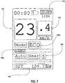
- the outputs 160 may also be wirelessly transmitted to and displayed on a separate display mounted to the handlebar 104 or another wireless device (e.g., a mobile device such as a cellular phone) not attached to the bicycle 100.
- the outputs 160 may be displayed on the separate display instead of or in addition to being displayed at the interface 132.
- a separate display 170 displays the battery level 160b, the power mode 160c, and the gear 160f with other information such as, for example, a speed 172, a distance traveled 174, and a battery level 176 for the separate display 170.
- the interface 132 includes an ambient light sensor configured to automatically adjust a brightness of one of the displays (e.g., a single OLED display that displays all of the outputs 160), such that the displayed outputs 160 may be visible in bright ambient conditions and not distracting or blinding in low ambient light conditions.
- an LED on the interface 132 may be used to sense the ambient light level.
- the ambient light sensor may be used to automatically turn on the bike headlights/taillights below a certain ambient light threshold.
- the interface 132 may wirelessly communicate with, for example, a passive wireless electronic device (e.g., a wireless key fob) carried by an owner of the bicycle 100 as a security measure. If the interface 132 detects that the wireless key fob is in sufficient proximity to the bicycle 100, all e-bike functions may be enabled. If the interface 132 does not detect the key fob, the e-bike functions may be disabled to prevent theft.
- a cell phone associated with the owner may be used interchangeably with a key fob as an unlocking device
- the controls and display on the interface 132 may serve as the primary and only controls to the e-bike control system 128.
- redundant controls may be provided on the handlebar 104 through the use of wireless input devices.
- a control such as control of the power output of the assist motor may be controlled at the interface 132 or the wireless remote at the handlebar 104.
- the interface 132 acts as a bridge; a signal generated by the remote button is transmitted wirelessly to the interface 132, and the interface 132 then communicates the generated signal to the e-bike control system 128. In this way, the interface 132 may control the same characteristic of the e-bike 100 through multiple inputs.
- FIG. 8 is a schematic showing a simplified representation of an e-bike system 180 including an embodiment of the interface 132.
- the interface 132 is connected by wire 136 to a first component 182 (e.g., the e-bike control system 128 including the battery 130 (not shown), and the assist motor 146 of the drive unit 138).
- the interface 132 is connected wirelessly to a second component 184 (e.g., a walk or boost button mounted to the handlebar 104).
- a second component 184 e.g., a walk or boost button mounted to the handlebar 104.
- the second component 184 which is located at the handlebar 104, may only transmit a wireless signal momentarily when actuated and may therefore be configured with a very small power supply and therefore be a very small device. This may allow the second component 184 to easily integrate into other handlebar-mounted devices such as shifters, brake levers, seat post controls, or even the handlebar 104 itself.
- the e-bike system 180 may include more, fewer, and/or different components.
- FIG. 9 is a more complicated schematic of an e-bike system 190 adding a third component 192 and a fourth component 194 to be controlled by the interface 132.
- the third component 192 and the fourth component 194 may be wired or wirelessly powered.
- the third component 192 and the fourth component 194 may be wired or wirelessly controlled.
- the third component 192 and the fourth component 194 may include electronic derailleur (e.g., the rear derailleur 122), height adjust seat posts, suspension devices such as suspension seat posts, front shocks, rear shocks or suspension frame elements. Additional devices may be accessories such as lights, speakers, air pressure control systems, cameras, or any other security related devices such as locks.
- the e-bike system 190 may include more, fewer, and/or different components.
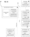
- FIG. 10 is a schematic of another e-bike system 200, adding the third component 192, the battery 130 (e.g., a system battery), and a sensor 202 compared to the example shown in FIG. 8 .
- the first component 182 is the drive unit 138.
- the system battery 130 may include a controller 204 (e.g., a microprocessor) and a wired communicator 206 (e.g., a wired interface).
- the communicator 206 may be a wireless communicator.
- the microprocessor 204 may track any number of parameters including, for example, battery voltage, battery temperature, current from battery, battery state of charge, individual cell voltage, charge cycles, on time, and/or any number of other parameters.
- the microprocessor 204 may control an output of the battery 130 (e.g., on/off, max current, voltage, etc.) to the rest of the e-bike system 200 based on these or other measured parameters.
- the wired communicator 206 of the battery 130 may be, for example, a CAN bus type.
- the wired communicator 206 may send, for example, status information to the rest of the e-bike system 200 and/or a charging system about a state of the battery (e.g., voltage, temperature, state of charge, individual cell voltage, serial number, etc.).
- the microprocessor 204 and the wired communicator 206 are used to authenticate the battery 130 to the rest of the e-bike system 200 to prevent third party batteries from being used in the e-bike system 200.
- the wired communicator 206 may be used to provide a firmware update to the microprocessor 204 to change the behavior of the battery 130.
- the wired communicator 206 of the battery 130 may communicate with all other devices on the wired CAN bus (e.g., the HMI 132, the drive unit 138, the sensor 202, etc.).
- e-bike speed sensors may communicate with the drive unit 138 with a timed digital pulse.
- This pulse may be referred to as a reed signal.
- This pulse may correspond with a single revolution of a wheel (e.g., the front wheel 108 or the rear wheel 112).
- the time between pulses may be used by the drive unit 138 to calculate wheel speed.
- Wheel speed data is used by the drive unit 138 to prevent providing motor assist to the rider above a legal speed threshold.
- Various system certification and safety designs may make it difficult to deviate from this legacy digital timing pulse. In the case of automatic shifting, it is desirable to have a wheel speed update rate that is higher than one pulse per revolution of the wheel.
- the sensor 202 is, for example, a speed sensor that is capable of updating at a higher rate than once per revolution of the wheel.
- the speed sensor 202 reports the speed data asynchronously to consumers of the speed data (e.g., the HMI 132) without having to change an interface to the drive unit 138.
- the asynchronous data may be transmitted on the CAN bus.
- the e-bike system 200 may employ any combination of CAN bus speed data broadcast to all devices on the CAN bus and/or a digital timed pulse interface between the speed sensor 202 and the drive unit 138 directly.
- all subsystems communicate wirelessly, as indicated by the dotted line.
- the subsystems communicating wirelessly may include, but are not limited to, the bicycle communication apparatus (HMI) 132, the speed sensor 202, the first component (drive unit) 182, the system battery 130, the second component 184, and the third component 192.
- HMI bicycle communication apparatus
- the subsystems communicating wirelessly may include, but are not limited to, the bicycle communication apparatus (HMI) 132, the speed sensor 202, the first component (drive unit) 182, the system battery 130, the second component 184, and the third component 192.
- the system battery 130 may provide power to the bicycle communication apparatus (HMI) 132, the speed sensor 202, the first component (drive unit) 182.
- HMI bicycle communication apparatus
- Other subsystems or devices may be connected to the system wirelessly and may include a separate power source or receive power from a separate power source than the system battery 130.
- the speed sensor 202 is optional in the embodiments of FIGS. 10 and 11 .
- the speed sensor 202 may optionally have a wired digital interface to the motor 146 in the first component 182, providing a digital signal 306.
- the battery 130 may report state of charge, temperature, or other telemetry to a battery charger wirelessly during charging process.
- inventions of the disclosure may be referred to herein, individually and/or collectively, by the term "invention" merely for convenience and without intending to voluntarily limit the scope of this application to any particular invention or inventive concept.
- inventions may be referred to herein, individually and/or collectively, by the term "invention" merely for convenience and without intending to voluntarily limit the scope of this application to any particular invention or inventive concept.
- specific embodiments have been illustrated and described herein, it should be appreciated that any subsequent arrangement designed to achieve the same or similar purpose may be substituted for the specific embodiments shown.
- This disclosure is intended to cover any and all subsequent adaptations or variations of various embodiments. Combinations of the above embodiments, and other embodiments not specifically described herein, are apparent to those of skill in the art upon reviewing the description.
Landscapes
- Engineering & Computer Science (AREA)
- Mechanical Engineering (AREA)
- Chemical & Material Sciences (AREA)
- Combustion & Propulsion (AREA)
- Transportation (AREA)
- Theoretical Computer Science (AREA)
- General Physics & Mathematics (AREA)
- Physics & Mathematics (AREA)
- General Engineering & Computer Science (AREA)
- Computer Hardware Design (AREA)
- Human Computer Interaction (AREA)
- Computer Networks & Wireless Communication (AREA)
- Power Engineering (AREA)
- Electric Propulsion And Braking For Vehicles (AREA)
- Motorcycle And Bicycle Frame (AREA)
- Non-Insulated Conductors (AREA)
- Traffic Control Systems (AREA)
Abstract
An e-bike interface (132) is a hybrid wired/wireless e-bike control system that integrates wireless bicycle components into operation of an e-bike (100). The e-bike interface (132) provides a frame-mounted control and display that is wired to, for example, an assist motor (138) and a battery (130), and provides a wireless communication bridge between wireless bicycle components and corresponding wireless controls located on a handlebar (104).
Description
- This application claims the benefit of
U.S. Provisional Patent Application No. 62/940354, filed November 26, 2019 - The present disclosure is generally directed to a human machine interface (HMI) and, more particularly, to an HMI for an e-bike.
- Electric drive systems are used to assist a rider of a bicycle to ride longer and/or faster. An assist motor and a battery are added to the bicycle to accomplish this as an electric bike (e.g., an e-bike). One type of e-bike requires pedaling to start the assist motor. A pedal force or pedal rotation is measured, and a controller of the e-bike controls the assist motor based on the measured pedal force or the measured pedal rotation. For example, the assist motor may be positioned on a frame of the e-bike, and the assist motor may provide motor assist at cranks of the e-bike. The motor assist may be provided based on the measured pedal force or the measured pedal rotation, such that a combined power of a power generated by the assist motor and a drive power input generated by the rider goes through a geared drivetrain of the e-bike.
- In one example, an interface includes a housing attachable to a first frame part of a bicycle, and a processor supported by the housing. The interface also includes a first communication interface and a second communication interface in communication with the processor. The first communication interface is a wired communication interface, and the second communication interface is a wireless communication interface. The interface includes an input in communication with the processor and supported by the housing. The input is configured to generate a first control signal based on a first user input. The processor is configured to receive a second control signal via the second communication interface. The second control signal is generated by a control device attached to a second frame part of the bicycle based on a second user input. The processor is also configured to control a component of the bicycle via the first communication interface based on the first control signal and the received second control signal.
- In one example, the first frame part is a top tube of the bicycle, and the second frame part is a handlebar of the bicycle.
- In one example, the input is a physical user interface.
- In one example, the processor is further configured to receive data representing characteristics related to the component of the bicycle from the component of the bicycle via the first communication interface.
- In one example, the interface further includes an output in communication with the processor. The output is configured to output a representation of at least one of the characteristics related to the component of the bicycle.
- In one example, the output is a display supported by the housing. The display is configured to display the representation of the at least one characteristic related to the component of the bicycle.
- In one example, the interface further includes an ambient light sensor configured to determine an amount of ambient light in an environment in which the interface is disposed. The processor is configured to change a brightness of the display based on the determined amount of ambient light in the environment.
- The component of the bicycle is an e-bike motor system. The e-bike motor system includes a drive motor and a battery. The characteristics related to the e-bike motor system includes battery power, a time to complete a charge, a charge rate, a percent state of charge, power level, speed, cadence, a system warning or error message, or any combination thereof.
- In one example, the component of the bicycle is an e-bike motor system. The e-bike motor system includes a drive motor and a battery. The processor is configured to be powered by the battery of the e-bike motor system via the first communication interface.
- In one example, the e-bike motor system further includes a drive motor. The processor is configured to control the drive motor of the e-bike motor system via the first communication interface based on the first control signal or the received second control signal.
- In one example, the control of the drive motor of the e-bike motor system based on the first control signal or the received second control signal comprises the processor being configured to turn the drive motor on or off, or change a power level of the drive motor.
- In one example, the control device attached to the second frame part of the bicycle is a wireless handlebar mounted e-bike control interface, a wireless handlebar mounted shifter or seat post control interface, a wireless handlebar mounted e-bike assist level control interface, or a wireless handlebar mounted automatic shifting control interface.
- In one example, the component is a first component. The processor is further configured to receive data from a second component of the bicycle, transmit data to the second component of the bicycle, or receive and transmit data to the second component of the bicycle.
- In one example, the interface further includes a third communication interface in communication with the processor. The third communication interface is a wireless communication interface. The processor is configured to receive the second control signal via the second communication interface using a first wireless communication protocol. The processor is configured to receive data from the second component of the bicycle, transmit data to the second component of the bicycle, or receive and transmit data to the second component of the bicycle via the third communication interface using a second wireless communication protocol. The second wireless communication protocol is different than the first wireless communication protocol.
- In one example, the second component of the bicycle is a wirelessly controlled derailleur, a wirelessly controlled front suspension fork, or a rear suspension shock.
- In one example, the component is a first component, and the first component receives a timed digital pulse from a speed sensor, the speed sensor communicates to the processor via the first communication interface.
- In one example, the processor is configured to communicate with a device outside of the bicycle via the second communication interface or a third communication interface. The third communication interface is different than the second communication interface and is a wireless communication interface. The processor is further configured to determine whether a signal from the device outside of the bicycle is received and allow operation of the component of the bicycle when the signal is received from the device outside of the bicycle.
- In one example, the device outside of the bicycle is a passive wireless electronic device or a mobile device.
- In one example, a bicycle communication apparatus for an e-bike includes a housing attachable to a top tube of a frame of a bicycle, a processor supported by the housing, and a wired communication interface in communication with the processor. The wired communication interface is wiredly connectable to an e-bike motor system. The e-bike motor system includes a drive motor. The bicycle communication apparatus further includes a wireless communication interface in communication with the processor. The wireless communication interface is wirelessly connectable to a control device attached to a handlebar of the bicycle. The bicycle communication apparatus includes an input supported by the housing and in communication with the processor. The input is configured to generate a first control signal based on a first user input. The processor is configured to receive a second control signal from the control device attached to the handlebar of the bicycle via the wireless communication interface. The second control signal is for the e-bike motor system and is generated by the control device based on a second user input. The processor is further configured to control the drive motor of the e-bike motor system via the wired communication interface based on the first control signal or the received second control signal.
- In one example, the wireless communication interface is a first wireless communication interface. The bicycle communication apparatus further includes a second wireless communication interface. The second wireless communication interface is in communication with the processor and is wirelessly connected to a movable component of the bicycle. The movable component of the bicycle is movable relative to the bicycle communication apparatus. The processor is in communication with the control device attached to the handlebar of the bicycle and the movable component of the bicycle using different wireless protocols, respectively.
- In one example, an e-bike system for a bicycle includes an e-bike motor system including a drive motor and a battery. The e-bike system also includes a bicycle communication apparatus. The bicycle communication apparatus includes a housing attachable to a frame of the bicycle, a processor supported by the housing, and a wired communication interface in communication with the processor. The wired communication interface is wiredly connected to the e-bike motor system. The bicycle communication apparatus also includes a wireless communication interface in communication with the processor. The wireless communication interface is wirelessly connectable to a control device attached to a handlebar of the bicycle. The bicycle communication apparatus includes an input supported by the housing and in communication with the processor. The input is configured to generate a first control signal based on a first user input. The processor of the bicycle communication apparatus is configured to receive a second control signal from the control device attached to the handlebar of the bicycle via the wireless communication interface. The second control signal is generated by the control device based on a second user input. The processor of the bicycle communication apparatus is further configured to control the drive motor of the e-bike motor system via the wired communication interface based on the first control signal or the received second control signal.
- Objects, features, and advantages of the present invention will become apparent upon reading the following description in conjunction with the drawing figures, in which:
-
FIG. 1 is a side view schematic of an e-bike that may be fitted with an interface in accordance with the teachings of this disclosure; -
FIG. 2 is a side view schematic of an example of a drive unit; -
FIG. 3 is an exemplary representation of an interface; -
FIG. 4 in a top view schematic of the e-bike ofFIG. 1 ; -
FIG. 5 is a close-up top view of a portion of the e-bike ofFIG. 4 ; -
FIG. 6 is a front view of an example of an interface; -
FIG. 7 is a front view of an example of a separate display device; -
FIG. 8 is a representation of a first example of an e-bike system; -
FIG. 9 is a representation of a second example of an e-bike system; -
FIG. 10 is a representation of a third example of an e-bike system; and -
FIG. 11 is a representation of a fourth example of an e-bike system. - A number of peripheral inputs are provided for control of an assist motor of an e-bike. Inputs such as, for example, power on/off, a power assist level, a battery level, and/or other inputs may be provided. Additionally, characteristics of the assist motor and the battery of the e-bike are to be displayed while the rider rides the e-bike. Characteristics such as, for example, battery level, a power setting, a gear indication, a speed, a cadence, a power, and/or other characteristics may be displayed to the rider.
- The rider is to be able to control the peripheral inputs and view the displayed characteristics while riding the e-bike (e.g., via a display). For e-bikes of the prior art, the peripheral inputs and the display may be located on the handlebar and may be a wired connection to a control system of the e-bike.
- Running a wire between the peripheral inputs and the display on the handlebar, and the e-bike system (e.g., including the battery and/or the assist motor) on the frame, however, is complex and runs a risk of failure due to movement of the handlebar, and thus the peripheral inputs and the display attached thereto, relative to the frame. The peripheral inputs and the display also compete for space if installed on the handlebar, as a full-featured mapping computer may also be installed on the handlebar.
- Other bicycle components are to be integrated into operation of the e-bike (e.g., the assist motor). The other bicycle components include, for example, electrically controlled derailleurs, gear hubs, suspension devices, height adjust seat posts, lights, audible devices, power meters, computing devices, other sensors such as cadence sensors, wheel speed sensors, inclination sensors, wind speed sensors, direction sensors, altitude sensors, seat pressure sensors, post height sensors, pedal force sensors, and/or other components. These bicycle components may be controlled wirelessly, as wires are a major source of failure on bicycle components (e.g., off-road mountain bicycles). The wireless bicycle components may be controlled by corresponding wireless controls located on the handlebar.
- The e-bike interface (e.g., a bicycle communication apparatus (BCA)) of the present embodiments is a hybrid wired/wireless e-bike control system that integrates wireless bicycle components into operation of an e-bike. The e-bike interface provides a frame-mounted control and display that is wired to, for example, the assist motor and the battery, and provides a wireless communication bridge between wireless bicycle components and corresponding wireless controls located on the handlebar.
- The e-bike interface may be configured to turn part of an e-bike system (e.g., the assist motor) on and off. The e-bike interface is further configured to display characteristics of the e-bike system such as, for example, battery power, gear indication, power level, speed, cadence, system warnings or error messages, and/or other information. A rider is able to change the power level for the e-bike system (e.g., the power level for the assist motor) via the e-bike interface. The e-bike interface acts as a communication bridge between a controller area network bus (CANBUS) of the wired e-bike system and a number of wireless components integrated into the function of the e-bike system. Examples of such wireless components include wireless handlebar-mounted walk to boost buttons, a wirelessly controlled rear derailleur, wireless handlebar-mounted shifter and seat post control units, a wirelessly controlled front suspension fork and/or a wirelessly controlled rear suspension shock, a wireless handlebar-mounted assist level button, and/or a wireless handlebar-mounted automatic shifting setting button.
- Turning now to the drawings,
FIG. 1 generally illustrates one example of abicycle 100 on which the disclosed interface may be implemented. In this example, thebicycle 100 may be a mountain bicycle. In some cases, thebicycle 100 may be an e-bike. Thebicycle 100 has aframe 102, ahandlebar 104 near a front end of theframe 102, and a seat or saddle 106 for supporting a rider over a top of theframe 102. Thebicycle 100 also has a first orfront wheel 108 carried by afront fork 110 of theframe 102 and supporting the front end of theframe 102. Thebicycle 100 also has a second orrear wheel 112 supporting a rear end of theframe 102. The rear end of theframe 102 may be connected to arear suspension component 114. Thebicycle 100 also has adrive train 116 with acrank assembly 118 that is operatively coupled via achain 120 and arear derailleur 122 to arear cassette 124 near a rotation axis of therear wheel 112. Thecrank assembly 118 includes twocranks 123 and twopedals 125 connected to the twocranks 123, respectively, on opposite sides of theframe 102 of thebicycle 100. - In the example shown, the
rear derailleur 122 includes a power source (e.g., a battery) and a motor, and receives instructions (e.g., wirelessly) from a controller 126 (e.g., a shifter or a central controller) mounted, for example, to thehandlebar 104 or an interface of the present embodiments to shift gears on therear cassette 124. In one embodiment, therear derailleur 112 receives instructions from an e-bike control system 128 (e.g., including one or more processors, control circuitry, and/or a power source 130) to shift gears on therear cassette 124. Therear derailleur 122 shift gears using the power source and the motor of therear derailleur 122, based on the received instructions. - In one embodiment, the
rear derailleur 122 is powered by a power source outside of therear derailleur 122. For example, therear derailleur 122 is powered by the power source 130 (e.g., a battery) of thee-bike control system 128. In another embodiment, therear derailleur 122 is connected to an input on the handlebar 104 (e.g., a shifter), for example, via a shifter cable and shifts gears on therear cassette 122 based on movement of the shifter (e.g., by the rider), and thus the shifter cable. - An interface 132 (e.g., a human machine interface (HMI)) may be mounted to the
frame 102 of thebicycle 100. For example, theinterface 132 may be mounted to atop tube 134 of theframe 102. Theinterface 132 may be coupled with the power source 130 (e.g., a battery) of thee-bike control system 128 via a wire 136 (e.g., a bus). - The
battery 130 of thee-bike control system 128 is also supported by theframe 102 of thebicycle 100. For example, thebattery 130 of thee-bike control system 128 is supported by abottom tube 137 of theframe 102 of thebicycle 100. Thewire 136 extends, for example, through part of thebottom tube 137 of theframe 102 and part of thetop tube 134 of the frame to electrically connect the e-bike control system 128 (e.g., the battery 130) and theinterface 132. Other components (e.g., the controller 126) may be coupled with thepower source 130 of thee-bike control system 128 via other wires, respectively. - In some cases, the
wire 136 may be sealed where thewire 136 exits theframe 102 of thebicycle 100. For example, epoxy or another sealing material may be disposed around thewire 136 where thewire 136 exits theframe 102. The material may form a potting seal around thewire 136. The sealing prevents ingress of water into theframe 102 of thebicycle 100 from outside of theframe 102. Additionally or alternatively, the sealing may reduce strain on thewire 136. - The
power source 130 powers theinterface 132 via thewire 136. Theinterface 132 may also receive data (e.g., instructions) from and/or send data to other components of the e-bike control system 128 (e.g., the one or more processors and/or the control circuitry) via thewire 136. - The
power source 130 also powers a drive unit 138 (e.g., including an e-bike motor) that is operatively coupled to the crankassembly 118. In one embodiment, theinterface 132 may also be powered by a separate battery to provide access to e-bike controls when thebattery 130 of thee-bike control system 128 is not attached to thebicycle 100. Theinterface 132 may also be in communication with multiple external wireless devices with or without thebattery 130 of thee-bike control system 128 being attached. - While the
bicycle 100 depicted inFIG. 1 is a mountain bicycle, theinterface 132, including the specific embodiments and examples disclosed herein as well as alternative embodiments and examples, may be implemented on other types of bicycles. For example, the disclosedinterface 132 may be used on road bicycles, as well as bicycles with mechanical (e.g., cable, hydraulic, pneumatic, etc.) and non-mechanical (e.g., wired, wireless) drive systems. The disclosedinterface 132 may also be implemented on other types of two-, three-, and four-wheeled human powered vehicles as well. - The
drive unit 138 is mounted to theframe 102 of thebicycle 100. For example, thedrive unit 138 is mounted to theframe 102 of thebicycle 100 with one or more bolts and threaded openings within theframe 102 of thebicycle 100. Thedrive unit 138 may be attached to theframe 102 in other ways. Referring toFIG. 2 , a crank axle runs through anopening 140 through thedrive unit 138 and connects the twocranks 123 of thecrank assembly 118. During operation, the rider rotates the twocranks 123 via the twopedals 125, rotating the crank axle. Thecrank assembly 118 may include sensors configured to measure axle rotation and forces on the axle. At least some of the sensors may, for example, be disposed on and/or within the crank axle. The crank axle drives anoutput ring 142 of thedrive unit 138 in a forward drive direction but not in a back pedaling direction through the use of, for example, a one-way clutch 144 between the crank axle and theoutput ring 142. - The measured axle rotation and the measured forces on the axle (e.g., by the sensors) may be used to control an electric drive motor 146 (e.g., an assist motor) of the
drive unit 138. Theassist motor 146 may directly or through the use of gears also drive rotation ofoutput ring 142. Theoutput ring 142 thus provides an output power to thedrive train 116 that is a combination of rider input power and an output power of theassist motor 146. - The
drive unit 138 may include internal electronics to control operation of theassist motor 146, measure axle inputs, measure an inclination of thebicycle 100, measure an acceleration of thebicycle 100, measure a temperature of thebicycle 100, and/or reduce a voltage of thebattery 130 of thee-bike control system 128 to accommodate and power external devices if lower voltages are required. Additional, fewer, and/or different internal electronics may be provided within thedrive unit 138. - A
housing 148 of thedrive unit 138 also acts as a heat sink to remove heat generated by theassist motor 146. Thehousing 148 of thedrive unit 138 may be made of any number of different thermally conductive materials including, for example, aluminum. Aluminum is light and a good heat dissipater. Aluminum, however, is not good at passing wireless signals. A controller of thedrive unit 138 may thus be disposed on thehousing 148 of thedrive unit 138 and wired to the internal electronics of thedrive unit 138. The controller of thedrive unit 138 may be made of a material through which wireless control signals may pass. In other embodiments, thehousing 148 is made of a different thermally conductive material (e.g., a thermally conductive plastic) that is more transmissive to wireless signals than aluminum. In one embodiment, the controller of thedrive unit 138 is wired to thee-bike control system 128. - Data from the drive unit 138 (e.g., the sensors of the drive unit 138) may be transmitted to the
interface 132.FIG. 3 is a representation of one embodiment of theinterface 132. As shown in the example ofFIG. 1 , theinterface 132 may be wired to the e-bike control system 128 (e.g., thebattery 130 of the e-bike control system 128). Alternatively or additionally, theinterface 132 may be wired to thedrive unit 138. Theinterface 132 may be powered directly from thebattery 130 of thee-bike control system 128. Theinterface 132, however, may operate at a voltage lower than thebattery 130 of thee-bike control system 128, and thee-bike control system 128, theinterface 132, or another component of thebicycle 100 may include a voltage reducer and/or a voltage regulator configured to reduce the battery voltage and/or maintain the reduced voltage. - The
interface 132 includes a controller 150 (e.g., an electronic control device), amemory 152, awired interface 154 for communication with one or more wired devices, wireless interfaces 156 for communication with one or more wireless devices,inputs 158, and outputs 160. Thecontroller 150, thememory 152, thewired interface 154, the wireless interfaces 156, theinputs 158, and theoutputs 160 are supported by one or more housings of theinterface 132. Theinterface 132 may include more, fewer, and/or different components. Thecontroller 150, thememory 152, thewired interface 154, the wireless interfaces 156, theinputs 158, and theoutputs 160 may be in communication with each other via one or more printed circuit boards (PCBs), wires, tracks, pads, and/or other components within theinterface 132. - The
controller 150 operates the interface 132 (e.g., determines what to display on theinterface 132, generates instructions based on rider interaction with the inputs 158). Thecontroller 150 may include any number of different types of controllers including, for example, a general processor, a central processing unit, a control processor, a graphics processor, a digital signal processor, an application-specific integrated circuit, a field-programmable gate array, a digital circuit, an analog circuit, combinations thereof, or other now known or later developed processing devices. Thecontroller 150 is a single device or multiple devices operating in serial, parallel, or separately. Thecontroller 150 is configured by instructions, design, hardware, and/or software to perform the acts discussed herein. - The
memory 152 is configured to store data regarding e-bike settings, usage, or use, or identification of external paired devices. Thememory 152 may also be configured to store data received from components of thebicycle 100 outside of the interface 132 (e.g., therear derailleur 122, thee-bike control system 128, and the shifters on the handlebar 104). Thememory 152 is a computer readable storage medium. Thememory 152 may include various types of volatile and non-volatile storage media, including but not limited to random access memory, read-only memory, programmable read-only memory, electrically programmable read-only memory, electrically erasable read-only memory, flash memory, magnetic tape or disk, optical media, and the like. Thememory 152 may be a single device or a combination of devices. Thememory 152 may be adjacent to, part of, networked with, and/or remote from theprocessor 150. - The
wired interface 154 may be any number of different wired interfaces that are configured to receive/transmit power and may be for any number of different wired communications on thebicycle 100. For example, thewired interface 154 may be a coaxial cable interface. More and/or different wired interfaces may be provided. - The
interface 132 may use multiple wireless protocols with either a single transmitter or multiple different transmitters in addition to the wired communication protocol used within the e-bike motor/battery system. For example, theinterface 132 may communicate with therear derailleur 122 with a derailleur protocol, a handheld device with Bluetooth or BTLE, and a wireless fitness device with a low power protocol such as ANT or ANT+. More, fewer, and/or different wireless protocols may be used. - In the example shown in
FIG. 3 , theinterface 132 includes threewireless interfaces first wireless interface 156a may be for communication with therear derailleur 122 and/or the shifters on thehandlebar 104, asecond wireless interface 156b (e.g., a Bluetooth interface) may be for communication with the handheld device, and athird wireless interface 156c (e.g., an ANT+ interface) may be for communication with the wireless fitness device. In one embodiment, theinterface 132 includes a single wireless interface configured to operate with the different wireless protocols. Theinterface 132 may include more, fewer, and/or different wireless interfaces. In one embodiment, theinterface 132 includes an input (e.g., a button or other input) to pair theinterface 132 with wireless components outside of theinterface 132 on the bicycle 100 (e.g., therear derailleur 122 and/or the shifters on the handlebar 104). - The
controller 150 of theinterface 132 acts as a bridge between thee-bike control system 128 and a user input (e.g., via theinputs 158 at the interface 132) and/or wireless devices (e.g., handlebar-mounted wireless control devices). Theinterface 132, via thecontroller 150 and the wireless interfaces 156, may communicate in multiple wireless protocols depending on the device theinterface 132 is communicating with. For example, theinterface 132 transforms signals to and from thee-bike control system 128, into a protocol that may be understood by the component receiving the signal (e.g., thee-bike control system 128, therear derailleur 122, or a handlebar-mounted control device). - The
interface 132 includesinputs 158 in the form of, for example, buttons, thoughother inputs 158 such as, for example, touch screen control or some other form of motion sensing through the use of sensors or cameras may be provided. In one embodiment, thebuttons 158 of theinterface 132, for example, may be dynamically backlit to be easier to find in dark conditions. The example ofFIG. 3 shows threeinput buttons 158, though more or fewer may be provided. - The
input buttons 158 may directly control components of thebicycle 100. For example, one or more of theinput buttons 158 may directly control thedrive unit 138 of thebicycle 100. In the example ofFIG. 3 , theinput buttons 158 include afirst input button 158a that turns thedrive unit 138 on or off, and asecond input button 158b that changes an output power mode of the drive unit 138 (e.g., low, medium, high, Turbo). The rider may, for example, press thesecond input button 158b a number of times until the output power mode of thedrive unit 138 to be selected (e.g., high) is displayed at theinterface 132. - The
interface 132 includesoutputs 160 in the form of displays, though other types ofoutputs 160 including, for example, audio outputs (e.g., speakers and/or a vibration circuit to indicate to the rider that particular configurations of thebicycle 100 have been reached, predetermined conditions have been met, and/or other occurrences) may be provided. Theinterface 132 may include one or more separate displays 160 (e.g., corresponding to different types of information to be displayed). - The example of
FIG. 3 illustrates six different displayedoutputs 160. More, fewer, and/or different displayed outputs and/or one or more audio outputs may be provided. For example, the example ofFIG. 3 illustrates a first displayedoutput 160a that indicates whether thedrive unit 138 is on or off. A second displayedoutput 160b indicates a battery level of a battery of thebicycle 100. For example, the second displayedoutput 160b indicates a battery level of thebattery 130 of thee-bike control system 128. A third displayedoutput 160c indicates an output power mode of the drive unit 138 (e.g., low, medium, high, Turbo). A fourth displayedoutput 160d indicates whether theinterface 132 is paired with one or more components of the bicycle 100 (e.g., shifters on thehandlebar 104 and/or the controller of the drive unit 138). A fifth displayedoutput 160e indicates different modes of the bicycle 100 (e.g., Auto v. Moto). A sixth displayedoutput 160f indicates a gear in which thebicycle 100 is currently being ridden. In one embodiment, another output is displayed when thebattery 130 of the e-bike 100 is charging. For example, theinterface 132 may display information about a battery charge cycle such as a remaining time to complete charge, a charge rate, and/or a percent state of charge. - The displayed outputs 160 may be provided within a single display (e.g., a single LCD screen). Alternatively, the displayed
outputs 160 may be broken into at least two groups displayed on at least two separate displays (e.g., two separate LCD screens). - Data based on which the displayed
outputs 160 are generated may be transmitted to theinterface 132 in any number of ways. For example, the data may be transmitted via thewire 136 and/or wirelessly from the corresponding components of thebicycle 100. For example, thee-bike control system 128 may identify and transmit the battery level of thebattery 130, whether thedrive unit 138 is on or off, and a power mode of thedrive unit 138 via thewire 136; the shifters on thehandlebar 104 or therear derailleur 122, for example, may identify and transmit a gear indication to theinterface 132 wirelessly. The data may be identified and transmitted at a predetermined time interval (e.g., every 0.1 second) and/or in response to a change (e.g., thedrive unit 138 being turned on or off). - Referring to
FIGS. 4 and5 , theinput buttons 158, for example, and the displayedoutputs 160 of theinterface 132 may be located at a position on thebicycle 100 where the rider may use theinput buttons 158 and see the displayedoutputs 160, respectively, during riding. As illustrated in the example ofFIGS. 4 and5 , theinterface 132 may be disposed on and/or in thetop tube 134 of theframe 102 at a position along thetop tube 134 of theframe 102 that is closer to thehandlebar 104 than thesaddle 106. Other positioning of theinterface 132 along thetop tube 134 or elsewhere on theframe 102 may be provided. - The
interface 132 may be attached to theframe 102 of thebicycle 100 in any number of ways. For example, thetop tube 134 of theframe 102 may include an opening sized and shaped to match at least a portion of theinterface 132, and theinterface 132 may be positioned within the opening. Thetop tube 134 may also include holes via which theinterface 132 may be connected to theframe 102 with connectors 162 (e.g., screws). Theinterface 132 may be attached to theframe 102 of thebicycle 100 in other ways. - In the example shown in
FIG. 6 , theinterface 132 includes two inputs 158 (e.g., thefirst input button 158a and thesecond input button 158b) and a single display 164 (e.g., to display one or more of the outputs 160). Thefirst input button 158a, for example, is a main switch that turns theassist motor 146 on and off, and thesecond input button 158b, with a short press, switches an assist level of the assist motor 146 (e.g., OFF, ECO, EMTB, Custom). Thedisplay 164 displays thesecond output 160b, battery level, thethird output 160c, and the power mode. Thedisplay 164 illustrates a battery level, via thesecond output 160b, of over 50% with a partially filled graphic of a battery, and illustrates the power mode, via thethird output 160c, with a highlighted mode (e.g., MTB). Thedisplay 164 also displays other information that may be useful to the rider. Data for such displayed information may be received by theinterface 132 wirelessly or via wired connection from any number of components of thebicycle 100. - The
inputs 158 of theinterface 132 may, however, serve dual purposes depending on the method of actuation. For example, the same button (e.g., thesecond button 158b) may change assist levels when pressed and released momentarily (e.g., approximately one second) but may execute a pairing program when pressed for a defined period of time (e.g., five or more seconds). - In one embodiment, the function of each of the
inputs 158 may be changed through the use of a setup tool such as a phone app, a computer program, or a series of operations on thebicycle 100 that change theinterface 132 into a setup mode where button functions are defined and changed. Similarly, display options may be programmed in the same way. The user may change display settings to modify content, graphic design, intensity, and duration of the information shown on thedisplay 164, for example. - In one embodiment, the
outputs 160 may also be wirelessly transmitted to and displayed on a separate display mounted to thehandlebar 104 or another wireless device (e.g., a mobile device such as a cellular phone) not attached to thebicycle 100. Theoutputs 160 may be displayed on the separate display instead of or in addition to being displayed at theinterface 132. Referring toFIG. 7 , aseparate display 170 displays thebattery level 160b, thepower mode 160c, and thegear 160f with other information such as, for example, aspeed 172, a distance traveled 174, and abattery level 176 for theseparate display 170. - In one embodiment, the
interface 132 includes an ambient light sensor configured to automatically adjust a brightness of one of the displays (e.g., a single OLED display that displays all of the outputs 160), such that the displayedoutputs 160 may be visible in bright ambient conditions and not distracting or blinding in low ambient light conditions. For example, an LED on theinterface 132 may be used to sense the ambient light level. In one embodiment, the ambient light sensor may be used to automatically turn on the bike headlights/taillights below a certain ambient light threshold. - The
interface 132 may wirelessly communicate with, for example, a passive wireless electronic device (e.g., a wireless key fob) carried by an owner of thebicycle 100 as a security measure. If theinterface 132 detects that the wireless key fob is in sufficient proximity to thebicycle 100, all e-bike functions may be enabled. If theinterface 132 does not detect the key fob, the e-bike functions may be disabled to prevent theft. In one embodiment, a cell phone associated with the owner may be used interchangeably with a key fob as an unlocking device - The controls and display on the
interface 132 may serve as the primary and only controls to thee-bike control system 128. In one embodiment, redundant controls may be provided on thehandlebar 104 through the use of wireless input devices. In this way, a control such as control of the power output of the assist motor may be controlled at theinterface 132 or the wireless remote at thehandlebar 104. However, if the remote button is used in such a configuration, theinterface 132 acts as a bridge; a signal generated by the remote button is transmitted wirelessly to theinterface 132, and theinterface 132 then communicates the generated signal to thee-bike control system 128. In this way, theinterface 132 may control the same characteristic of the e-bike 100 through multiple inputs. -
FIG. 8 is a schematic showing a simplified representation of ane-bike system 180 including an embodiment of theinterface 132. Theinterface 132 is connected bywire 136 to a first component 182 (e.g., thee-bike control system 128 including the battery 130 (not shown), and theassist motor 146 of the drive unit 138). Theinterface 132 is connected wirelessly to a second component 184 (e.g., a walk or boost button mounted to the handlebar 104). In this way, all the complicated functionality of inputs and displays are directly wired to theinterface 132 and mounted on thebicycle frame 104, operable and visible to the bike rider with a large supply of power from thebattery 130 of thee-bike control system 128. In this way, thedisplay 164 remains on and may be very bright, while minimizing a risk of wearing out thebattery 130. Thesecond component 184, which is located at thehandlebar 104, may only transmit a wireless signal momentarily when actuated and may therefore be configured with a very small power supply and therefore be a very small device. This may allow thesecond component 184 to easily integrate into other handlebar-mounted devices such as shifters, brake levers, seat post controls, or even thehandlebar 104 itself. Thee-bike system 180 may include more, fewer, and/or different components. -
FIG. 9 is a more complicated schematic of an e-bike system 190 adding athird component 192 and afourth component 194 to be controlled by theinterface 132. Thethird component 192 and thefourth component 194 may be wired or wirelessly powered. Thethird component 192 and thefourth component 194 may be wired or wirelessly controlled. Thethird component 192 and thefourth component 194 may include electronic derailleurs (e.g., the rear derailleur 122), height adjust seat posts, suspension devices such as suspension seat posts, front shocks, rear shocks or suspension frame elements. Additional devices may be accessories such as lights, speakers, air pressure control systems, cameras, or any other security related devices such as locks. The e-bike system 190 may include more, fewer, and/or different components. -
FIG. 10 is a schematic of anothere-bike system 200, adding thethird component 192, the battery 130 (e.g., a system battery), and asensor 202 compared to the example shown inFIG. 8 . In the example, thefirst component 182 is thedrive unit 138. Thesystem battery 130 may include a controller 204 (e.g., a microprocessor) and a wired communicator 206 (e.g., a wired interface). In an alternate embodiment, thecommunicator 206 may be a wireless communicator. Themicroprocessor 204 may track any number of parameters including, for example, battery voltage, battery temperature, current from battery, battery state of charge, individual cell voltage, charge cycles, on time, and/or any number of other parameters. Themicroprocessor 204 may control an output of the battery 130 (e.g., on/off, max current, voltage, etc.) to the rest of thee-bike system 200 based on these or other measured parameters. - The
wired communicator 206 of thebattery 130 may be, for example, a CAN bus type. Thewired communicator 206 may send, for example, status information to the rest of thee-bike system 200 and/or a charging system about a state of the battery (e.g., voltage, temperature, state of charge, individual cell voltage, serial number, etc.). In one embodiment, themicroprocessor 204 and thewired communicator 206 are used to authenticate thebattery 130 to the rest of thee-bike system 200 to prevent third party batteries from being used in thee-bike system 200. Thewired communicator 206 may be used to provide a firmware update to themicroprocessor 204 to change the behavior of thebattery 130. Thewired communicator 206 of thebattery 130 may communicate with all other devices on the wired CAN bus (e.g., theHMI 132, thedrive unit 138, thesensor 202, etc.). - Typically, e-bike speed sensors may communicate with the
drive unit 138 with a timed digital pulse. This pulse may be referred to as a reed signal. This pulse may correspond with a single revolution of a wheel (e.g., thefront wheel 108 or the rear wheel 112). The time between pulses may be used by thedrive unit 138 to calculate wheel speed. Wheel speed data is used by thedrive unit 138 to prevent providing motor assist to the rider above a legal speed threshold. Various system certification and safety designs may make it difficult to deviate from this legacy digital timing pulse. In the case of automatic shifting, it is desirable to have a wheel speed update rate that is higher than one pulse per revolution of the wheel. - The
sensor 202 is, for example, a speed sensor that is capable of updating at a higher rate than once per revolution of the wheel. Thespeed sensor 202 reports the speed data asynchronously to consumers of the speed data (e.g., the HMI 132) without having to change an interface to thedrive unit 138. For example, the asynchronous data may be transmitted on the CAN bus. Accordingly, thee-bike system 200 may employ any combination of CAN bus speed data broadcast to all devices on the CAN bus and/or a digital timed pulse interface between thespeed sensor 202 and thedrive unit 138 directly. - It may be desirable to power many or all electronic subsystems on an e-bike from the
battery 130 to minimize the number of batteries requiring recharge or replacement. Additionally, accomplishing communication between devices wirelessly may be desirable to reduce the complexity of physical interconnects between devices, even if they already include power connections between components. In another embodiment, as illustrated inFIG. 11 , all subsystems communicate wirelessly, as indicated by the dotted line. For example. the subsystems communicating wirelessly may include, but are not limited to, the bicycle communication apparatus (HMI) 132, thespeed sensor 202, the first component (drive unit) 182, thesystem battery 130, thesecond component 184, and thethird component 192. Several subsystems are powered by thesystem battery 130 withwires 302. For example, thesystem battery 130 may provide power to the bicycle communication apparatus (HMI) 132, thespeed sensor 202, the first component (drive unit) 182. Other subsystems or devices may be connected to the system wirelessly and may include a separate power source or receive power from a separate power source than thesystem battery 130. Thespeed sensor 202 is optional in the embodiments ofFIGS. 10 and11 . Thespeed sensor 202 may optionally have a wired digital interface to themotor 146 in thefirst component 182, providing adigital signal 306. Additionally, thebattery 130 may report state of charge, temperature, or other telemetry to a battery charger wirelessly during charging process. - The illustrations of the embodiments described herein are intended to provide a general understanding of the structure of the various embodiments. The illustrations are not intended to serve as a complete description of all of the elements and features of apparatus and systems that utilize the structures or methods described herein. Many other embodiments may be apparent to those of skill in the art upon reviewing the disclosure. Other embodiments may be utilized and derived from the disclosure, such that structural and logical substitutions and changes may be made without departing from the scope of the disclosure. Additionally, the illustrations are merely representational and may not be drawn to scale. Certain proportions within the illustrations may be exaggerated, while other proportions may be minimized. Accordingly, the disclosure and the figures are to be regarded as illustrative rather than restrictive.
- While this specification contains many specifics, these should not be construed as limitations on the scope of the invention or of what may be claimed, but rather as descriptions of features specific to particular embodiments of the invention. Certain features that are described in this specification in the context of separate embodiments can also be implemented in combination in a single embodiment. Conversely, various features that are described in the context of a single embodiment can also be implemented in multiple embodiments separately or in any suitable sub-combination. Moreover, although features may be described above as acting in certain combinations and even initially claimed as such, one or more features from a claimed combination can in some cases be excised from the combination, and the claimed combination may be directed to a sub-combination or variation of a sub-combination.
- Similarly, while operations and/or acts are depicted in the drawings and described herein in a particular order, this should not be understood as requiring that such operations be performed in the particular order shown or in sequential order, or that all illustrated operations be performed, to achieve desirable results. In certain circumstances, multitasking and parallel processing may be advantageous. Moreover, the separation of various system components in the embodiments described above should not be understood as requiring such separation in all embodiments, and it should be understood that any described program components and systems can generally be integrated together in a single software product or packaged into multiple software products.
- One or more embodiments of the disclosure may be referred to herein, individually and/or collectively, by the term "invention" merely for convenience and without intending to voluntarily limit the scope of this application to any particular invention or inventive concept. Moreover, although specific embodiments have been illustrated and described herein, it should be appreciated that any subsequent arrangement designed to achieve the same or similar purpose may be substituted for the specific embodiments shown. This disclosure is intended to cover any and all subsequent adaptations or variations of various embodiments. Combinations of the above embodiments, and other embodiments not specifically described herein, are apparent to those of skill in the art upon reviewing the description.
- The Abstract of the Disclosure is provided to comply with 37 C.F.R. §1.72(b) and is submitted with the understanding that it will not be used to interpret or limit the scope or meaning of the claims. In addition, in the foregoing Detailed Description, various features may be grouped together or described in a single embodiment for the purpose of streamlining the disclosure. This disclosure is not to be interpreted as reflecting an intention that the claimed embodiments require more features than are expressly recited in each claim. Rather, as the following claims reflect, inventive subject matter may be directed to less than all of the features of any of the disclosed embodiments. Thus, the following claims are incorporated into the Detailed Description, with each claim standing on its own as defining separately claimed subject matter.
- It is intended that the foregoing detailed description be regarded as illustrative rather than limiting and that it is understood that the following claims including all equivalents are intended to define the scope of the invention. The claims should not be read as limited to the described order or elements unless stated to that effect. Therefore, all embodiments that come within the scope and spirit of the following claims and equivalents thereto are claimed as the invention.
Claims (15)
- An interface comprising:a housing attachable to a first frame part of a bicycle;a processor supported by the housing;a first communication interface and a second communication interface in communication with the processor, wherein the first communication interface is a wired communication interface, and the second communication interface is a wireless communication interface; andan input in communication with the processor and supported by the housing, the input being configured to generate a first control signal based on a first user input,wherein the processor is configured to:receive a second control signal via the second communication interface, the second control signal being generated by a control device attached to a second frame part of the bicycle based on a second user input; andcontrol a component of the bicycle via the first communication interface based on the first control signal and the received second control signal.
- The interface of claim 1, wherein the first frame part is a top tube of the bicycle, and the second frame part is a handlebar of the bicycle, wherein as an optional feature the input is a physical user interface.
- The interface of one of the preceding claims, wherein the processor is further configured to receive data representing characteristics related to the component of the bicycle from the component of the bicycle via the first communication interface.
- The interface of claim 3, further comprising an output in communication with the processor,
wherein the output is configured to output a representation of at least one of the characteristics related to the component of the bicycle. - The interface of claim 3 or 4, wherein the output is a display supported by the housing, and
wherein the display is configured to display the representation of the at least one characteristic related to the component of the bicycle. - The interface of one of the preceding claims, further comprising an ambient light sensor configured to determine an amount of ambient light in an environment in which the interface is disposed,
wherein the processor is configured to change a brightness of the display based on the determined amount of ambient light in the environment. - The interface of one of claims 4 to 6, wherein the component of the bicycle is an e-bike motor system, the e-bike motor system including a drive motor and a battery, and
wherein the characteristics related to the e-bike motor system include battery power, a time to complete a charge, a charge rate, a percent state of charge, power level, speed, cadence, a system warning or error message, or any combination thereof. - The interface of one of the claims 1 to 6, wherein the component of the bicycle is an e-bike motor system, the e-bike motor system including a battery, and
wherein the processor is configured to be powered by the battery of the e-bike motor system via the first communication interface. - The interface of claim 8, wherein the e-bike motor system further includes a drive motor, and
wherein the processor is configured to control the drive motor of the e-bike motor system via the first communication interface based on the first control signal or the received second control signal, wherein in particular the control of the drive motor of the e-bike motor system based on the first control signal or the received second control signal comprises the processor being configured to turn the drive motor on or off, or change a power level of the drive motor. - The interface of one of the preceding claims, wherein the control device attached to the second frame part of the bicycle is a wireless handlebar mounted e-bike control interface, a wireless handlebar mounted shifter or seat post control interface, a wireless handlebar mounted e-bike assist level control interface, or a wireless handlebar mounted automatic shifting control interface.
- The interface of one of the preceding claims, wherein the component is a first component, and
wherein the processor is further configured to receive data from a second component of the bicycle, transmit data to the second component of the bicycle, or receive and transmit data to the second component of the bicycle. - The interface of one of the preceding claims, further comprising a third communication interface in communication with the processor, the third communication interface being a wireless communication interface,
wherein the processor is configured to receive the second control signal via the second communication interface using a first wireless communication protocol, and
wherein the processor is configured to receive data from the second component of the bicycle, transmit data to the second component of the bicycle, or receive and transmit data to the second component of the bicycle via the third communication interface using a second wireless communication protocol, the second wireless communication protocol being different than the first wireless communication protocol. - The interface of claim 11 or 12, wherein the second component of the bicycle is a wirelessly controlled derailleur, a wirelessly controlled front suspension fork, or a rear suspension shock.
- The interface of claim 10, wherein the component is a first component, and the first component receives a timed digital pulse from a speed sensor, the speed sensor communicates to the processor via the first communication interface.
- The interface of one of the preceding claims, wherein the processor is configured to communicate with a device outside of the bicycle via the second communication interface or a third communication interface, the third communication interface being different than the second communication interface and being a wireless communication interface,
wherein the processor is further configured to:identify whether a signal from the device outside of the bicycle is received; andallow operation of the component of the bicycle when the signal is received from the device outside of the bicycle,wherein as an optional feature the device outside of the bicycle is a passive wireless electronic device or a mobile device.
Applications Claiming Priority (2)
| Application Number | Priority Date | Filing Date | Title |
|---|---|---|---|
| US201962940354P | 2019-11-26 | 2019-11-26 | |
| US17/101,627 US12246795B2 (en) | 2019-11-26 | 2020-11-23 | Interface for electric assist bicycle |
Publications (1)
| Publication Number | Publication Date |
|---|---|
| EP3828071A1 true EP3828071A1 (en) | 2021-06-02 |
Family
ID=73598750
Family Applications (1)
| Application Number | Title | Priority Date | Filing Date |
|---|---|---|---|
| EP20210032.7A Pending EP3828071A1 (en) | 2019-11-26 | 2020-11-26 | Interface for electric assist bicycle |
Country Status (5)
| Country | Link |
|---|---|
| US (2) | US12246795B2 (en) |
| EP (1) | EP3828071A1 (en) |
| CN (2) | CN115848552A (en) |
| DE (1) | DE102020131357A1 (en) |
| TW (3) | TWI808359B (en) |
Cited By (3)
| Publication number | Priority date | Publication date | Assignee | Title |
|---|---|---|---|---|
| NL2031513B1 (en) * | 2022-04-05 | 2023-10-25 | Vanmoof Bv | Electric bicycle with control device and communicating external charger device |
| DE102023205672A1 (en) | 2023-06-16 | 2024-12-19 | Mahle International Gmbh | Control device for an electric bicycle and electric bicycle with the same |
| DE102024201940A1 (en) * | 2024-03-01 | 2025-09-04 | Robert Bosch Gesellschaft mit beschränkter Haftung | Electric motor-driven vehicle and display unit for an electric motor-driven vehicle |
Families Citing this family (18)
| Publication number | Priority date | Publication date | Assignee | Title |
|---|---|---|---|---|
| US10472015B1 (en) | 2018-06-28 | 2019-11-12 | Specialized Bicycle Components, Inc. | In-frame mounted bicycle monitoring device |
| CN115214834A (en) | 2021-04-20 | 2022-10-21 | Sram德国有限公司 | Electric bicycle drive unit, bicycle frame for an electric bicycle drive unit, frame interface unit and energy accumulator device |
| US12589822B2 (en) | 2021-05-25 | 2026-03-31 | Specialized Bicycle Components, Inc. | In-frame mounted bicycle display |
| TW202304735A (en) * | 2021-07-30 | 2023-02-01 | 日商島野股份有限公司 | Operating device for human-powered vehicle and human-powered vehicle |
| JP2023020831A (en) * | 2021-07-30 | 2023-02-09 | 株式会社シマノ | Operation device of man-powered vehicle, and man-powered vehicle |
| DE102021209424B4 (en) * | 2021-08-27 | 2024-08-01 | Zf Friedrichshafen Ag | Power distribution unit for an electric bicycle and bicycle |
| US11964725B2 (en) | 2021-08-31 | 2024-04-23 | Sram, Llc | Low power control for a control device for a bicycle |
| US20230257059A1 (en) * | 2021-09-02 | 2023-08-17 | Rudi Pienaar | Handlebar apparatus with an integral electronic device |
| CN114348168B (en) * | 2021-12-22 | 2023-12-26 | 富士康(昆山)电脑接插件有限公司 | Wireless control system of electric bicycle and electric bicycle with same |
| JP2023097166A (en) * | 2021-12-27 | 2023-07-07 | 株式会社シマノ | Components for human powered vehicles |
| IT202200005816A1 (en) * | 2022-03-24 | 2023-09-24 | Campagnolo Srl | COMMUNICATION METHODS IN AN ELECTRONIC BICYCLE SYSTEM |
| US12414170B2 (en) | 2022-11-30 | 2025-09-09 | Sram, Llc | Power on pairing for electronic components of a bicycle |
| JP2024123418A (en) | 2023-03-01 | 2024-09-12 | 株式会社シマノ | CONTROL SYSTEM FOR HUMAN-POWERED VEHICLE AND TRANSMISSION DEVICE FOR HUMAN-POWERED VEHICLE |
| TWI846480B (en) * | 2023-05-22 | 2024-06-21 | 西勝國際股份有限公司 | Auxiliary components for bicycles |
| DE102023135803A1 (en) * | 2023-12-19 | 2025-06-26 | Brose Antriebstechnik GmbH & Co. Kommanditgesellschaft, Berlin | Drive system for an electric bicycle with a control unit and method for determining pedal power |
| US20250220732A1 (en) * | 2023-12-27 | 2025-07-03 | Shimano Inc. | Human-powered vehicle component, human-powered vehicle control system, and non-transitory computer-readable storage medium |
| EP4671101A1 (en) * | 2024-06-26 | 2025-12-31 | Koninklijke Philips N.V. | ELECTRONIC DEVICE WITH OPERATING MODES AND METHOD FOR SWITCHING BETWEEN OPERATING MODES |
| US12497134B1 (en) * | 2025-06-04 | 2025-12-16 | Hazem Nihad Hamed | Electrical derailleur controller |
Citations (10)
| Publication number | Priority date | Publication date | Assignee | Title |
|---|---|---|---|---|
| US6352486B1 (en) * | 2001-01-12 | 2002-03-05 | Sram Corporation | Semi-automatic shifting system |
| US20120253601A1 (en) * | 2011-03-31 | 2012-10-04 | Shimano Inc. | Bicycle component control apparatus |
| WO2014205345A2 (en) * | 2013-06-20 | 2014-12-24 | Product Development Technologies Llc | Bicycle system |
| US20160216169A1 (en) * | 2015-01-23 | 2016-07-28 | Shimano Inc. | Bicycle pedaling force detector |
| EP3127799A1 (en) * | 2015-08-07 | 2017-02-08 | Armando Mastracci | Automatic gear selection for multi-geared, pedal-operated vehicles |
| US20170043829A1 (en) * | 2015-08-11 | 2017-02-16 | Le Holdings (Beijing) Co., Ltd. | Bicycle and parking control device thereof |
| US20190002053A1 (en) * | 2017-06-29 | 2019-01-03 | Shimano Inc. | Bicycle electrical component |
| WO2019043576A1 (en) * | 2017-08-29 | 2019-03-07 | Mystromer Ag | ELECTRIC BICYCLE WITH COMMUNICATION SYSTEM |
| US10472015B1 (en) * | 2018-06-28 | 2019-11-12 | Specialized Bicycle Components, Inc. | In-frame mounted bicycle monitoring device |
| US20200377167A1 (en) * | 2019-05-30 | 2020-12-03 | Shimano Inc. | Control device and control system including control device |
Family Cites Families (31)
| Publication number | Priority date | Publication date | Assignee | Title |
|---|---|---|---|---|
| US6243685B1 (en) * | 1999-02-08 | 2001-06-05 | Rick C. Bergman | Voice operated interactive message display system for vehicles |
| US6781510B2 (en) | 2002-07-24 | 2004-08-24 | Shimano, Inc. | Bicycle computer control arrangement and method |
| JP2004249885A (en) | 2003-02-21 | 2004-09-09 | Cateye Co Ltd | Handlebar stem and speed indicating device |
| US11029199B2 (en) * | 2012-06-22 | 2021-06-08 | Fitbit, Inc. | Ambient light determination using physiological metric sensor data |
| US9561734B2 (en) | 2012-07-31 | 2017-02-07 | Shimano Inc. | Bicycle power supply system |
| US20140181715A1 (en) * | 2012-12-26 | 2014-06-26 | Microsoft Corporation | Dynamic user interfaces adapted to inferred user contexts |
| ITMI20130895A1 (en) | 2013-05-31 | 2014-12-01 | Campagnolo Srl | ELECTRONIC BICYCLE SYSTEM |
| JP2015027861A (en) | 2013-07-05 | 2015-02-12 | 株式会社シマノ | Bicycle control system |
| US9229712B2 (en) * | 2013-09-10 | 2016-01-05 | Shimano Inc. | Bicycle component control apparatus |
| JP6280856B2 (en) * | 2014-10-31 | 2018-02-14 | 株式会社シマノ | Bicycle control system |
| US10029754B2 (en) * | 2015-03-06 | 2018-07-24 | Shimano Inc. | Bicycle electrical system |
| US9573654B2 (en) | 2015-04-28 | 2017-02-21 | Shimano Inc. | Bicycle controller |
| US9491788B1 (en) * | 2015-06-17 | 2016-11-08 | Shimano Inc. | Bicycle wireless system |
| ITUB20152302A1 (en) | 2015-07-20 | 2017-01-20 | Campagnolo Srl | Electronic bicycle system |
| CN204916028U (en) * | 2015-08-27 | 2015-12-30 | 苏州福豪斯电子科技有限公司 | Electric bicycle control system |
| CN105270558B (en) * | 2015-10-16 | 2018-09-14 | 新安乃达驱动技术(上海)股份有限公司 | Electric bicycle and the automobile-used wireless control system of electrical salf-walking |
| JP6631185B2 (en) * | 2015-11-17 | 2020-01-15 | 日本精機株式会社 | Display device |
| KR102496341B1 (en) * | 2016-02-12 | 2023-02-06 | 에이치엘만도 주식회사 | Electric bicycle |
| CN205686519U (en) * | 2016-06-13 | 2016-11-16 | 京东方科技集团股份有限公司 | A kind of intelligent bicycle |
| JP6894195B2 (en) * | 2016-06-14 | 2021-06-30 | 株式会社シマノ | Bicycle display device |
| CN205827889U (en) * | 2016-06-28 | 2016-12-21 | 江苏北斗星通汽车电子有限公司 | Car navigator with automatic screen brightness adjustment |
| JP6798808B2 (en) * | 2016-07-11 | 2020-12-09 | 株式会社シマノ | Bicycle controls, bicycle components, and bicycle control systems |
| CN206327520U (en) * | 2016-11-18 | 2017-07-14 | 海贝(天津)科技有限责任公司 | The control system of electric assisted bicycle |
| JP6425762B2 (en) * | 2017-04-26 | 2018-11-21 | 三菱電機株式会社 | Display device of motorcycle |
| CN207241802U (en) * | 2017-06-27 | 2018-04-17 | 龙海特尔福汽车电子研究所有限公司 | A kind of brushless motor controller |
| US10377444B2 (en) * | 2017-07-31 | 2019-08-13 | Shimano Inc. | Bicycle electric component |
| JP7311240B2 (en) | 2017-10-06 | 2023-07-19 | 株式会社シマノ | bicycle radio unit |
| US10829173B2 (en) | 2017-12-21 | 2020-11-10 | Shimano Inc. | Bicycle seatpost assembly |
| JP6993272B2 (en) * | 2018-03-22 | 2022-01-13 | 株式会社シマノ | Control device for human-powered vehicles |
| CN209142297U (en) * | 2018-12-03 | 2019-07-23 | 南京懂玫驱动技术有限公司 | A kind of electric bicycle instrument with positioning function |
| US11554834B2 (en) * | 2019-07-29 | 2023-01-17 | Shimano Inc. | Operating system for human-powered vehicle |
-
2020
- 2020-11-23 US US17/101,627 patent/US12246795B2/en active Active
- 2020-11-25 TW TW109141420A patent/TWI808359B/en active
- 2020-11-25 TW TW112123435A patent/TWI824985B/en active
- 2020-11-25 TW TW112144297A patent/TW202426335A/en unknown
- 2020-11-26 CN CN202310019098.4A patent/CN115848552A/en active Pending
- 2020-11-26 EP EP20210032.7A patent/EP3828071A1/en active Pending
- 2020-11-26 DE DE102020131357.8A patent/DE102020131357A1/en active Pending
- 2020-11-26 CN CN202011344997.4A patent/CN112849320B/en active Active
-
2024
- 2024-07-24 US US18/782,538 patent/US20240375749A1/en active Pending
Patent Citations (10)
| Publication number | Priority date | Publication date | Assignee | Title |
|---|---|---|---|---|
| US6352486B1 (en) * | 2001-01-12 | 2002-03-05 | Sram Corporation | Semi-automatic shifting system |
| US20120253601A1 (en) * | 2011-03-31 | 2012-10-04 | Shimano Inc. | Bicycle component control apparatus |
| WO2014205345A2 (en) * | 2013-06-20 | 2014-12-24 | Product Development Technologies Llc | Bicycle system |
| US20160216169A1 (en) * | 2015-01-23 | 2016-07-28 | Shimano Inc. | Bicycle pedaling force detector |
| EP3127799A1 (en) * | 2015-08-07 | 2017-02-08 | Armando Mastracci | Automatic gear selection for multi-geared, pedal-operated vehicles |
| US20170043829A1 (en) * | 2015-08-11 | 2017-02-16 | Le Holdings (Beijing) Co., Ltd. | Bicycle and parking control device thereof |
| US20190002053A1 (en) * | 2017-06-29 | 2019-01-03 | Shimano Inc. | Bicycle electrical component |
| WO2019043576A1 (en) * | 2017-08-29 | 2019-03-07 | Mystromer Ag | ELECTRIC BICYCLE WITH COMMUNICATION SYSTEM |
| US10472015B1 (en) * | 2018-06-28 | 2019-11-12 | Specialized Bicycle Components, Inc. | In-frame mounted bicycle monitoring device |
| US20200377167A1 (en) * | 2019-05-30 | 2020-12-03 | Shimano Inc. | Control device and control system including control device |
Non-Patent Citations (2)
| Title |
|---|
| BOSCH GMBH ROBERT: "Active Line/Performance Line Active Line/Performance Line", 22 May 2017 (2017-05-22), pages 1 - 98, XP093020588, Retrieved from the Internet <URL:https://www.bosch-ebike.com/de/help-center/manuals/bedienungsanleitung-purion-14549> [retrieved on 20230203] * |
| SPECIALIZED: "SPECIALIZED TURBO LEVO USER MANUAL", MORGAN HILL, CA, 1 November 2018 (2018-11-01), MORGAN HILL, Ca, pages 1 - 224, XP093205613, Retrieved from the Internet <URL:https://media.specialized.com/support/collateral/0000108696.pdf> [retrieved on 20240916] * |
Cited By (3)
| Publication number | Priority date | Publication date | Assignee | Title |
|---|---|---|---|---|
| NL2031513B1 (en) * | 2022-04-05 | 2023-10-25 | Vanmoof Bv | Electric bicycle with control device and communicating external charger device |
| DE102023205672A1 (en) | 2023-06-16 | 2024-12-19 | Mahle International Gmbh | Control device for an electric bicycle and electric bicycle with the same |
| DE102024201940A1 (en) * | 2024-03-01 | 2025-09-04 | Robert Bosch Gesellschaft mit beschränkter Haftung | Electric motor-driven vehicle and display unit for an electric motor-driven vehicle |
Also Published As
| Publication number | Publication date |
|---|---|
| TW202128492A (en) | 2021-08-01 |
| DE102020131357A1 (en) | 2021-05-27 |
| US20240375749A1 (en) | 2024-11-14 |
| CN112849320B (en) | 2023-01-31 |
| TWI808359B (en) | 2023-07-11 |
| TW202426335A (en) | 2024-07-01 |
| CN115848552A (en) | 2023-03-28 |
| US12246795B2 (en) | 2025-03-11 |
| US20210155315A1 (en) | 2021-05-27 |
| TWI824985B (en) | 2023-12-01 |
| TW202340032A (en) | 2023-10-16 |
| CN112849320A (en) | 2021-05-28 |
Similar Documents
| Publication | Publication Date | Title |
|---|---|---|
| US20240375749A1 (en) | Interface for electric assist bicycle | |
| US11407475B2 (en) | Bicycle derailleur | |
| EP3088289B1 (en) | Center-mounted control system of bicycle | |
| CN110316310B (en) | Control device for human-powered vehicle | |
| EP2686229B1 (en) | Wheel for pedal-assisted bikes | |
| US11597470B2 (en) | Human-powered vehicle component, mobile electronic device, and equipment for human-powered vehicle | |
| CN110316308B (en) | Control device for human-powered vehicle | |
| US11731723B2 (en) | Rider recognition device for human-powered vehicle and control system of human-powered vehicle | |
| US20200012964A1 (en) | Control data creation device, component control device, control data creation method, component control method and computer program | |
| CN105936316A (en) | electric system for bicycle | |
| JP2001187593A (en) | Display device for bicycle with back light | |
| TWI248589B (en) | Signal output device for a bicycle and riding parameter display system for a bicycle using the same | |
| JP2019006244A (en) | Bicycle control device and bicycle drive system including the same | |
| CN114348162B (en) | Automatic speed-changing electric power-assisted bicycle, control method thereof and mobile terminal | |
| JP2019151255A (en) | Control device | |
| US20240351657A1 (en) | Electrical device and rotational device for human-powered vehicle | |
| EP1520777B1 (en) | Electronic control device for bicycle | |
| TW202043092A (en) | Control device for human-powered vehicle | |
| US20250256804A1 (en) | Detection system, detection method, and computer-readable storage medium | |
| JP4250160B2 (en) | Bicycle display device | |
| JP7849237B2 (en) | Control device for human-powered vehicles, and control system for human-powered vehicles | |
| CN108791689A (en) | Bicycle automatic speed changing unit and bicycle automatic speed changing system comprising same | |
| US20250206411A1 (en) | Bicycle component | |
| US20240246629A1 (en) | Bicycle component | |
| TW201942003A (en) | Device and control system for wireless communication |
Legal Events
| Date | Code | Title | Description |
|---|---|---|---|
| PUAI | Public reference made under article 153(3) epc to a published international application that has entered the european phase |
Free format text: ORIGINAL CODE: 0009012 |
|
| STAA | Information on the status of an ep patent application or granted ep patent |
Free format text: STATUS: REQUEST FOR EXAMINATION WAS MADE |
|
| 17P | Request for examination filed |
Effective date: 20201126 |
|
| AK | Designated contracting states |
Kind code of ref document: A1 Designated state(s): AL AT BE BG CH CY CZ DE DK EE ES FI FR GB GR HR HU IE IS IT LI LT LU LV MC MK MT NL NO PL PT RO RS SE SI SK SM TR |
|
| STAA | Information on the status of an ep patent application or granted ep patent |
Free format text: STATUS: EXAMINATION IS IN PROGRESS |
|
| 17Q | First examination report despatched |
Effective date: 20230210 |