EP3828069A1 - Attitude control actuator unit and leaning vehicle - Google Patents
Attitude control actuator unit and leaning vehicle Download PDFInfo
- Publication number
- EP3828069A1 EP3828069A1 EP19854344.9A EP19854344A EP3828069A1 EP 3828069 A1 EP3828069 A1 EP 3828069A1 EP 19854344 A EP19854344 A EP 19854344A EP 3828069 A1 EP3828069 A1 EP 3828069A1
- Authority
- EP
- European Patent Office
- Prior art keywords
- vehicle
- body frame
- vehicle body
- posture control
- leaning
- Prior art date
- Legal status (The legal status is an assumption and is not a legal conclusion. Google has not performed a legal analysis and makes no representation as to the accuracy of the status listed.)
- Granted
Links
Images






Classifications
-
- B—PERFORMING OPERATIONS; TRANSPORTING
- B62—LAND VEHICLES FOR TRAVELLING OTHERWISE THAN ON RAILS
- B62J—CYCLE SADDLES OR SEATS; AUXILIARY DEVICES OR ACCESSORIES SPECIALLY ADAPTED TO CYCLES AND NOT OTHERWISE PROVIDED FOR, e.g. ARTICLE CARRIERS OR CYCLE PROTECTORS
- B62J45/00—Electrical equipment arrangements specially adapted for use as accessories on cycles, not otherwise provided for
- B62J45/40—Sensor arrangements; Mounting thereof
- B62J45/41—Sensor arrangements; Mounting thereof characterised by the type of sensor
- B62J45/415—Inclination sensors
- B62J45/4151—Inclination sensors for sensing lateral inclination of the cycle
-
- B—PERFORMING OPERATIONS; TRANSPORTING
- B62—LAND VEHICLES FOR TRAVELLING OTHERWISE THAN ON RAILS
- B62K—CYCLES; CYCLE FRAMES; CYCLE STEERING DEVICES; RIDER-OPERATED TERMINAL CONTROLS SPECIALLY ADAPTED FOR CYCLES; CYCLE AXLE SUSPENSIONS; CYCLE SIDECARS, FORECARS, OR THE LIKE
- B62K11/00—Motorcycles, engine-assisted cycles or motor scooters with one or two wheels
- B62K11/007—Automatic balancing machines with single main ground engaging wheel or coaxial wheels supporting a rider
-
- B—PERFORMING OPERATIONS; TRANSPORTING
- B62—LAND VEHICLES FOR TRAVELLING OTHERWISE THAN ON RAILS
- B62D—MOTOR VEHICLES; TRAILERS
- B62D37/00—Stabilising vehicle bodies without controlling suspension arrangements
-
- B—PERFORMING OPERATIONS; TRANSPORTING
- B62—LAND VEHICLES FOR TRAVELLING OTHERWISE THAN ON RAILS
- B62J—CYCLE SADDLES OR SEATS; AUXILIARY DEVICES OR ACCESSORIES SPECIALLY ADAPTED TO CYCLES AND NOT OTHERWISE PROVIDED FOR, e.g. ARTICLE CARRIERS OR CYCLE PROTECTORS
- B62J45/00—Electrical equipment arrangements specially adapted for use as accessories on cycles, not otherwise provided for
- B62J45/40—Sensor arrangements; Mounting thereof
- B62J45/41—Sensor arrangements; Mounting thereof characterised by the type of sensor
- B62J45/415—Inclination sensors
-
- B—PERFORMING OPERATIONS; TRANSPORTING
- B62—LAND VEHICLES FOR TRAVELLING OTHERWISE THAN ON RAILS
- B62K—CYCLES; CYCLE FRAMES; CYCLE STEERING DEVICES; RIDER-OPERATED TERMINAL CONTROLS SPECIALLY ADAPTED FOR CYCLES; CYCLE AXLE SUSPENSIONS; CYCLE SIDECARS, FORECARS, OR THE LIKE
- B62K21/00—Steering devices
- B62K21/12—Handlebars; Handlebar stems
-
- B—PERFORMING OPERATIONS; TRANSPORTING
- B62—LAND VEHICLES FOR TRAVELLING OTHERWISE THAN ON RAILS
- B62K—CYCLES; CYCLE FRAMES; CYCLE STEERING DEVICES; RIDER-OPERATED TERMINAL CONTROLS SPECIALLY ADAPTED FOR CYCLES; CYCLE AXLE SUSPENSIONS; CYCLE SIDECARS, FORECARS, OR THE LIKE
- B62K21/00—Steering devices
- B62K21/18—Connections between forks and handlebars or handlebar stems
-
- B—PERFORMING OPERATIONS; TRANSPORTING
- B62—LAND VEHICLES FOR TRAVELLING OTHERWISE THAN ON RAILS
- B62K—CYCLES; CYCLE FRAMES; CYCLE STEERING DEVICES; RIDER-OPERATED TERMINAL CONTROLS SPECIALLY ADAPTED FOR CYCLES; CYCLE AXLE SUSPENSIONS; CYCLE SIDECARS, FORECARS, OR THE LIKE
- B62K5/00—Cycles with handlebars, equipped with three or more main road wheels
- B62K5/02—Tricycles
- B62K5/027—Motorcycles with three wheels
-
- B—PERFORMING OPERATIONS; TRANSPORTING
- B62—LAND VEHICLES FOR TRAVELLING OTHERWISE THAN ON RAILS
- B62K—CYCLES; CYCLE FRAMES; CYCLE STEERING DEVICES; RIDER-OPERATED TERMINAL CONTROLS SPECIALLY ADAPTED FOR CYCLES; CYCLE AXLE SUSPENSIONS; CYCLE SIDECARS, FORECARS, OR THE LIKE
- B62K5/00—Cycles with handlebars, equipped with three or more main road wheels
- B62K5/02—Tricycles
- B62K5/05—Tricycles characterised by a single rear wheel
-
- B—PERFORMING OPERATIONS; TRANSPORTING
- B62—LAND VEHICLES FOR TRAVELLING OTHERWISE THAN ON RAILS
- B62K—CYCLES; CYCLE FRAMES; CYCLE STEERING DEVICES; RIDER-OPERATED TERMINAL CONTROLS SPECIALLY ADAPTED FOR CYCLES; CYCLE AXLE SUSPENSIONS; CYCLE SIDECARS, FORECARS, OR THE LIKE
- B62K5/00—Cycles with handlebars, equipped with three or more main road wheels
- B62K5/08—Cycles with handlebars, equipped with three or more main road wheels with steering devices acting on two or more wheels
-
- B—PERFORMING OPERATIONS; TRANSPORTING
- B62—LAND VEHICLES FOR TRAVELLING OTHERWISE THAN ON RAILS
- B62K—CYCLES; CYCLE FRAMES; CYCLE STEERING DEVICES; RIDER-OPERATED TERMINAL CONTROLS SPECIALLY ADAPTED FOR CYCLES; CYCLE AXLE SUSPENSIONS; CYCLE SIDECARS, FORECARS, OR THE LIKE
- B62K5/00—Cycles with handlebars, equipped with three or more main road wheels
- B62K5/10—Cycles with handlebars, equipped with three or more main road wheels with means for inwardly inclining the vehicle body on bends
-
- B—PERFORMING OPERATIONS; TRANSPORTING
- B62—LAND VEHICLES FOR TRAVELLING OTHERWISE THAN ON RAILS
- B62D—MOTOR VEHICLES; TRAILERS
- B62D9/00—Steering deflectable wheels not otherwise provided for
- B62D9/02—Steering deflectable wheels not otherwise provided for combined with means for inwardly inclining vehicle body on bends
-
- B—PERFORMING OPERATIONS; TRANSPORTING
- B62—LAND VEHICLES FOR TRAVELLING OTHERWISE THAN ON RAILS
- B62K—CYCLES; CYCLE FRAMES; CYCLE STEERING DEVICES; RIDER-OPERATED TERMINAL CONTROLS SPECIALLY ADAPTED FOR CYCLES; CYCLE AXLE SUSPENSIONS; CYCLE SIDECARS, FORECARS, OR THE LIKE
- B62K2202/00—Motorised scooters
Definitions
- the present teaching relates to a posture control actuator unit and a leaning vehicle including a posture control actuator configured to output a posture control torque to control the posture of a vehicle body frame.
- a motorcycle disclosed in Patent Literature 1 is known as a conventional leaning vehicle.
- This motorcycle includes a vehicle body frame and an IMU (inertial measurement unit).
- the vehicle body frame leans leftward when the motorcycle is turning left and leans rightward when the motorcycle is turning right.
- the IMU includes three kinds of angular rate sensors and three kinds of acceleration sensors.
- the IMU obtains the pitch rate, the yaw rate and the roll rate of the vehicle body frame from the three kinds of angular rate sensors.
- the IMU obtains the acceleration in an x-axis direction, the acceleration in a y-axis direction and the acceleration in a z-axis direction of the vehicle body frame from the three kinds of acceleration sensors.
- the x-axis direction is a left-right direction of the motorcycle in an upright posture.
- the y-axis direction is an up-down direction of the motorcycle in an upright posture.
- the z-axis direction is a front-back direction of the motorcycle in an upright posture.
- the pitch rate is an angular rate when the vehicle body frame is rotating around the x-axis.
- the yaw rate is an angular rate when the vehicle body frame is rotating around the y-axis.
- the roll rate is an angular rate when the vehicle body frame is rotating around the z-axis.
- the IMU can calculate the speed of the motorcycle and the angle of the vehicle body frame, based on the pitch rate, the yaw rate, the roll rate, the acceleration in the x-axis direction, the acceleration in the y-axis direction and the acceleration in the z-axis direction.
- the IMU calculates a bank angle of the vehicle body frame based on the roll rate.
- the bank angle is an angle formed by the y-axis and a center line of the vehicle body frame in a backward view thereof.
- the center line of the vehicle body frame is a line extending along the y-axis from a center of the vehicle body frame in an upright posture with respect to a vehicle-body-frame-left-right direction in a backward view thereof.
- the vehicle body-frame-left-right direction is the left-right direction of the vehicle body frame.
- the IMU detects the posture (angle) of the vehicle body frame, such as a bank angle or the like.
- Patent Literature 1 Japanese Unexamined Patent Application Publication (Translation of PCT Application) No. 2016-531046
- a posture change such as a roll rate is required in some cases, depending on what kind of posture control is employed for posture control of the vehicle body frame. Then, in some leaning vehicles, the posture control of the vehicle body frame is possibly performed based on the roll rate detected by an angular rate sensor included in an IMU. For accurate posture control of the vehicle body frame, it is preferred to detect the roll rate accurately.
- an object of the present teaching is to provide a posture control actuator unit including an angular rate sensor that can detect a posture change of a vehicle body frame with high accuracy and a leaning vehicle.
- the present inventors conducted studies about detection of a posture change (angular rate) of a vehicle body frame by use of an IMU.
- the IMU includes an acceleration sensor and an angular rate sensor.
- the acceleration sensor is to detect the acceleration of the vehicle body frame caused by a run of the leaning vehicle.
- the acceleration of the vehicle body frame includes an acceleration of the vehicle body frame caused by a run of the leaning vehicle and an acceleration of the vehicle body frame caused by engine vibration.
- the absolute value of the acceleration of the vehicle body frame caused by engine vibration is greater than the absolute value of the acceleration of the vehicle body frame caused by a run of the leaning vehicle. For example, the absolute value of the acceleration of the vehicle body frame caused by engine vibration is tens of G.
- the absolute value of the acceleration of the vehicle body frame caused by a run of the leaning vehicle is several G.
- the acceleration of the vehicle body frame caused by engine vibration is noise for detection of the acceleration of the vehicle body frame caused by a run of the leaning vehicle. Therefore, the acceleration sensor preferably detects the acceleration of the vehicle body frame caused by a run of the leaning vehicle while not detecting the acceleration of the vehicle body frame caused by engine vibration.
- such an IMU is typically attached to a vehicle body frame via an elastic member such as a rubber mount or the like. This makes it harder for engine vibration to propagate to the vehicle body frame, and the acceleration sensor can accurately detect the acceleration of the vehicle body frame caused by a run of the leaning vehicle.
- the present inventors found that there are some cases in which the elastic member prevents the IMU from accurately detecting a posture change (angular rate) of the vehicle body frame. More specifically, when the vehicle body frame makes a posture change, an inertial force acts on the IMU, and the rubber mount is deformed. Accordingly, a posture change of the angular rate sensor of the IMU delays from the posture change of the vehicle body frame.
- the present inventors conducted studies about what kind of sensor is necessary to detect a posture change of a vehicle body frame. Then, the present inventors found out that an angular rate sensor is necessary to detect a posture change of a vehicle body frame and that an acceleration sensor is not necessary. The present inventors conceived of not using the angular rate sensor of the IMU but using an angular rate sensor disposed outside the IMU for detection of a posture change of the vehicle body frame. Then, it would become possible to attach the angular rate sensor to the vehicle body frame not via an elastic member. This would inhibit a delay of a posture change of the angular rate sensor from a posture change of the vehicle body frame, and detection of a posture change of a leaning vehicle by use of an angular rate sensor would become more accurate.
- an angular rate sensor is to detect a posture change (angular rate) of a vehicle body frame, and therefore, the angular rate sensor is required to be attached to the vehicle body frame in a proper position and in a proper direction (which will hereinafter be referred to as with high positional accuracy).
- the present inventors conducted studies about where in a vehicle body frame an angular rate sensor can be attached with high positional accuracy.
- the present inventors took notice of a posture control actuator used for posture control of the vehicle body frame.
- the posture control actuator is configured to output posture control power to control the posture of the vehicle body frame. Therefore, the posture control actuator is designed to be positioned at a predetermined angle to a roll axis or the like that is associated with a posture change of the vehicle body frame.
- the posture control actuator when the posture control actuator is an EPS actuator, in some cases, the posture control actuator is positioned such that the rotation axis thereof is parallel to a steering shaft.
- the posture control actuator when the posture control actuator is an EPL actuator, in some cases, the posture control actuator is positioned such that the rotation axis thereof is parallel to a rotation axis of the vehicle body frame.
- a posture control actuator is attached to a vehicle body frame with high positional accuracy.
- the present inventors conceived of using an existing posture control actuator for attachment of an angular rate sensor to a vehicle body frame. In other words, the present inventors conceived of integrating an angular rate sensor and a posture control actuator into a posture control actuator unit and attaching the posture control actuator unit to a vehicle body frame.
- the posture control actuator controller controls the operation of the link mechanism, based on the roll rate of the vehicle body frame accurately detected by the roll rate sensor.
- the link mechanism operates, the vehicle body frame rotates around the roll axis. Therefore, the posture control actuator controller of the leaning vehicle of (7) can control the posture of the vehicle body frame with high accuracy.
- the present teaching permits highly accurate detection of a posture change of a vehicle body frame by use of an angular rate sensor.
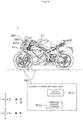
- FIG. 1 is a looking-to-the-right (R) view of the leaning vehicle 1.
- a posture control actuator unit 599 is used for the leaning vehicle 1, wherein the vehicle body frame 21 leans leftward when the leaning vehicle 1 is turning left and leans rightward when the leaning vehicle 1 is turning right.
- the posture control actuator unit 599 includes a posture control actuator 600o and an angular rate sensor 602o.
- the posture control actuator 600o is configured to output posture control power to control the posture of the vehicle body frame 21.
- the posture control actuator 600o is, for example, an EPS actuator, an EPL actuator, or the like.
- the rotation angle of the vehicle body frame 21 around the rotation axis Axo changes, and the angular rate sensor 602o is configured to detect the angular rate that is the amount of change per unit time of the rotation angle.
- the rotation axis Axo is, for example, a roll axis, a pitch axis, a yaw axis, or the like.
- the angular rate is, for example, a roll rate, a pitch rate, a yaw rate, or the like.
- the posture control actuator unit 599 is supported by the vehicle body frame 21 in such a manner as to be attachable to and detachable from the vehicle body frame 21, and the posture control actuator 600o and the angular rate sensor 602o are incorporated in such a manner as not to be displaceable relative to each other.
- the statement that "the posture control actuator unit 599 is supported by the vehicle body frame 21 in such a manner as to be attachable to and detachable from the vehicle body frame 21" means, for example, that the posture control actuator unit 599 is fastened to the vehicle body frame 21 via a fastener member such as a screw, a combination of a bolt and a nut, or the like.
- the statement that "the posture control actuator unit 599 is supported by the vehicle body frame 21 in such a manner as to be attachable to and detachable from the vehicle body frame 21" includes, for example, that the posture control actuator unit 599 is fastened to the vehicle body frame 21 mainly via a fastener member such as a screw, a combination of a bolt and a nut, or the like, and subsidiarily via an adhesive.
- the statement that the posture control actuator 600o and the angular rate sensor 602o are not displaceable relative to each other means that the relative positional relationship between the posture control actuator 600o and the angular rate sensor 602o is not variable.
- a first member and a second member are not displaceable relative to each other, it also means that there is no elastic member for impact absorption, such as a rubber mount or the like, in the power transmission route between the first member and the second member.
- the angular rate sensor 602o of the posture control actuator unit 599 can detect a posture change of the vehicle body frame 21 with high accuracy. More specifically, the posture control actuator 600o outputs posture control power to control the posture of the vehicle body frame 21.
- the posture control actuator unit 599 is supported by the vehicle body frame 21 in such a manner as to be attachable to and detachable from the vehicle body frame 21. This inhibits a delay of a posture change of the posture control actuator 600o from a posture change of the vehicle body frame 21.
- the posture control actuator 600o and the angular rate sensor 602o are incorporated in such a manner as not to be displaceable relative to each other.
- the angular rate sensor 602o of the posture control actuator unit 599 can detect a posture change of the vehicle body frame 21 with high accuracy.
- the angular rate sensor 602o of the posture control actuator unit 599 can detect a posture change of the vehicle body frame 21 with high accuracy. More specifically, the posture control actuator 600o outputs posture control power to control the posture of the vehicle body frame 21.
- the posture control actuator 600o is designed to be positioned at a predetermined angle to the roll axis or the like that is associated with the posture change of the vehicle body frame 21.
- the posture control actuator 600o may be positioned such that the rotation axis of the posture control actuator 600o is parallel to a steering shaft.
- the posture control actuator 600o when the posture control actuator 600o is an EPL actuator, the posture control actuator 600o may be positioned such that the rotation axis of the posture control actuator 600o is parallel to a rotation axis of the vehicle body frame 21.
- the posture control actuator 600o is attached to the vehicle body frame 21 with high positional accuracy.
- the posture control actuator 600o and the angular rate sensor 602o are incorporated in such a manner as not to be displaceable relative to each other.
- the angular rate sensor 602o is also mounted at a sensor mounting position of the vehicle body frame 21 with high positional accuracy. Therefore, the angular rate sensor 600o of the posture control actuator unit 599 can detect a posture change of the vehicle body frame 21 with high accuracy.
- the posture control actuator 600o of the posture control actuator unit 599 is attached to the vehicle body frame 21 with high positional accuracy. Therefore, it is easy to make the axis for the angular rate detection carried out by the angular rate sensor 602o almost parallel to the rotation axis Axo of the vehicle body frame 21. Accordingly, the angular rate sensor 602o can detect the angular rate of the vehicle body frame 21 with high accuracy.
- the angle formed between the axis for the angular rate detection carried out by the angular rate sensor 602o and the rotation axis Axo of the vehicle body frame 21 is easily identified. Then, it is easy to make a correction to the angular rate detected by the angular rate sensor 602o.
- the posture control actuator unit 599 can be downsized. More specifically, in the posture control actuator unit 599, the posture control actuator 600o and the angular rate sensor 602o are incorporated in such a manner as not to be displaceable relative to each other. Therefore, it is not necessary to provide a mount for attachment of the angular rate sensor 602o to the vehicle body frame 21. Accordingly, the number of components of the posture control actuator unit 599 is reduced, and the posture control actuator unit 599 is downsized.
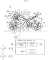
- FIG. 1B is a looking-to-the-right (R) view of the leaning vehicle 1a.
- FIG. 2 is a schematic looking-to-the-back (B) view of the leaning vehicle 1a.
- the leaning vehicle 1a is in an upright posture. Since FIG. 2 is a schematic view, there are some inconsistencies in size, etc. between FIG. 1B and FIG. 2.
- FIG. 2 shows only principal parts, and a vehicle body cover 22 is omitted in FIG. 2 .
- a forward direction in a front-back direction of the leaning vehicle 1a is referred to as a forward direction F (leaning-vehicle-forward direction).
- a backward direction in the front-back direction of the leaning vehicle 1a is referred to as a backward direction B (leaning-vehicle-backward direction).
- a leftward direction in a left-right direction of the leaning vehicle 1a is referred to as a leftward direction L (leaning-vehicle-leftward direction).
- a rightward direction in the left-right direction of the leaning vehicle 1a is referred to as a rightward direction R (leaning-vehicle-rightward direction).
- An upward direction in an up-down direction of the leaning vehicle 1a is referred to as an upward direction U (leaning-vehicle-upward direction).
- a downward direction in an up-down direction of the leaning vehicle 1a is referred to as a downward direction D (leaning-vehicle-downward direction).
- the front-back direction of the leaning vehicle 1a is referred to as a front-back direction FB (leaning-vehicle-front-back direction).
- the left-right direction of the leaning vehicle 1a is referred to as a left-right direction LR (leaning-vehicle-left-right direction).
- the up-down direction of the leaning vehicle 1a is referred to as an up-down direction UD (leaning-vehicle-up-down direction).
- the forward direction in the front-back direction of the leaning vehicle 1a is a forward direction relative to a rider straddling the leaning vehicle 1a.
- the backward direction in the front-back direction of the leaning vehicle 1a is a backward direction relative to a rider straddling the leaning vehicle 1a.
- the leftward direction in the left-right direction of the leaning vehicle 1a is a leftward direction relative to a rider straddling the leaning vehicle 1a.
- the rightward direction in the left-right direction of the leaning vehicle 1a is a rightward direction relative to a rider straddling the leaning vehicle 1a.
- the upward direction in the up-down direction of the leaning vehicle 1a is an upward direction relative to a rider straddling the leaning vehicle 1a.
- the downward direction in the up-down direction of the leaning vehicle 1a is a downward direction relative to a rider straddling the leaning vehicle 1a.
- the vehicle body frame 21 of the leaning vehicle 1a is capable of leaning in the leftward direction L and the rightward direction R.
- the up-down direction and the left-right direction of the vehicle body frame 21 do not respectively coincide with the up-down direction UD and the left-right direction LR of the leaning vehicle 1a.
- the vehicle body frame 21 is in an upright posture, the up-down direction and the left-right direction of the vehicle body frame 21 coincide with the up-down direction UD and the left-right direction LR, respectively, of the leaning vehicle 1a.
- a forward direction along the front-back direction of the vehicle body frame 21 is referred to as a forward direction f (vehicle-body-frame-forward direction).
- a backward direction along the front-back direction of the vehicle body frame 21 is referred to as a backward direction b (vehicle-body-frame-backward direction).
- a leftward direction along the left-right direction of the vehicle body frame 21 is referred to as a leftward direction 1 (vehicle-body-frame-leftward direction).
- a rightward direction along the left-right direction of the vehicle body frame 21 is referred to as a rightward direction r (vehicle-body-frame-rightward direction).
- An upward direction along the up-down direction of the vehicle body frame 21 is referred to as an upward direction u (vehicle-body-frame-upward direction).
- a downward direction along the up-down direction of the vehicle body frame 21 is referred to as a downward direction d (vehicle-body-frame-downward direction).
- the front-back direction of the vehicle body frame 21 is referred to as a front-back direction fb (vehicle-body-frame-front-back direction).
- the left-right direction of the vehicle body frame 21 is referred to as a left-right direction lr (vehicle-body-frame-left-right direction).
- the up-down direction of the vehicle body frame 21 is referred to as an up-down direction ud (vehicle-body-frame-up-down direction).
- a shaft or a member that extends along the front-back direction does not necessarily mean a shaft or a member that extends in parallel to the front-back direction.
- a shaft or a member that extends along the front-back direction includes a shaft or a member that is inclined from the front-back direction at an angle within ⁇ 45 degrees.
- a shaft or a member that extends along the up-down direction includes a shaft or a member that is inclined from the up-down direction at an angle within ⁇ 45 degrees.
- a shaft or a member that extends along the left-right direction includes a shaft or a member that is inclined from the left-right direction at an angle within ⁇ 45 degrees.
- the upright posture of the vehicle body frame 21 means a state wherein nobody is riding the leaning vehicle 1a, the leaning vehicle 1a is out of fuel, and the front wheel is neither steered nor caused to lean.
- a statement that a first member is supported by a second member includes a case in which the first member is attached to the second member such that the first member is immovable (that is, fixed in a place) relative to the second member and a case in which the first member is attached to the second member such that the first member is movable relative to the second member.
- the statement that the first member is supported by the second member also includes a case in which the first member is directly attached to the second member and a case in which the first member is attached to the second member via a third member.
- a statement that the first member and the second member are arranged in the front-back direction means the following situation.
- both the first member and the second member are on an arbitrary line representing the front-back direction.
- a statement that the first member and the second member are arranged in the front-back direction when viewed along the up-down direction means the following situation.
- both the first member and the second member are on an arbitrary line representing the front-back direction.
- both the first member and the second member are not necessarily on the arbitrary line representing the front-back direction.
- the first member and the second member may be in contact with each other.
- the first member and the second member may be out of contact with each other.
- a third member may be positioned between the first member and the second member.
- first member is positioned farther in the forward direction than the second member means the following situation.
- the first member is positioned farther in the forward direction than a plane that passes a front edge of the second member and is perpendicular to the front-back direction.
- the first member and the second member may or may not be arranged in the front-back direction. This definition applies to other directions as well as the front-back direction.
- the statement that the first member is positioned in front of the second member means the following situation. At least a part of the first member is positioned in a range that the second member passes during a translation thereof in the forward direction. Accordingly, the first member may be positioned within the range that the second member passes during a translation thereof in the forward direction, or may protrude from the range that the second member passes during a translation thereof in the forward direction. In this case, the first member and the second member are arranged in the front-back direction. This definition applies to other directions as well as the front-back direction.
- a statement that the first member is positioned in front of the second member in a view along the left-right direction means the following situation.
- the first member and the second member are arranged in the front-back direction in a view along the left-right direction, and the part of the first member facing the second member is positioned farther in the forward direction than the second member in a view along the left-right direction.
- three-dimensionally, the first member and the second member are not necessarily arranged in the front-back direction. This definition applies to other directions as well as the front-back direction.
- parts of the first member are defined as follows.
- a front part of the first member means the front half of the first member.
- a rear part of the first member means the rear half of the first member.
- a left part of the first member means the left half of the first member.
- a right part of the first member means the right half of the first member.
- An upper part of the first member means the upper half of the first member.
- a lower part of the first member means the lower half of the first member.
- An upper edge of the first member means the edge of the first member in the upward direction.
- a lower edge of the first member means the edge of the first member in the downward direction.
- a front edge of the first member means the edge of the first member in the forward direction.
- a rear edge of the first member means the edge of the first member in the backward direction.
- a right edge of the first member means the edge of the first member in the rightward direction.
- a left edge of the first member means the edge of the first member in the leftward direction.
- An upper end part of the first member means the upper edge and its vicinity of the first member.
- a lower end part of the first member means the lower edge and its vicinity of the first member.
- a front end part of the first member means the front edge and its vicinity of the first member.
- a rear end part of the first member means the rear edge and its vicinity of the first member.
- a right end part of the first member means the right edge and its vicinity of the first member.
- a left end part of the first member means the left edge and its vicinity of the first member.
- the first member is a component of the leaning vehicle 1a.
- the leaning vehicle 1a includes a vehicle body 2, a front wheel 3, a rear wheel 4, and a steering mechanism 7.
- the vehicle body 2 includes a vehicle body frame 21, a vehicle body cover 22, a seat 24, a power unit 25, and a swing arm 26.
- the vehicle body frame 21 leans in the leftward direction L when the leaning vehicle 1a is turning left.
- the vehicle body frame 21 leans in the rightward direction R when the leaning vehicle 1a is turning right.
- the vehicle body frame 21 is indicated by bold lines.
- the vehicle body frame 21 is covered by the vehicle body cover 22, and therefore, under ordinary conditions, the vehicle body frame 21 cannot be seen in FIG. 1B .
- the vehicle body frame 21 includes a head pipe 211, a main frame 212, and a seat rail 213.
- the head pipe 211 is positioned in the front part of the leaning vehicle 1a.
- the front part of the leaning vehicle 1a is a part thereof that is farther in the forward direction f than the front edge of the seat 24.
- the rear part of the leaning vehicle 1a is a part thereof that is farther in the backward direction b than the front edge of the seat 24.
- the head pipe 211 is inclined from the up-down direction ud such that the upper end part of the head pipe 211 is positioned farther in the backward direction b than the lower end part of the head pipe 211.
- the main frame 212 is positioned farther in the backward direction b than the head pipe 211.
- the seat rail 213 linearly extends from the main frame 212 to a backward and upward direction b, u.
- the swing arm 26 extends from the lower and rear part of the main frame 212 to the backward direction b.
- the swing arm 26 is supported by the main frame 212 in such a manner as to be capable of turning on the front end part of the swing arm 26.
- the rear end part of the swing arm 26 is movable up and down.
- the vehicle body cover 22 covers the vehicle body frame 21.
- the vehicle body cover 22 also covers some part of the power unit 25.
- the seat 24 is to be sat on by a rider.
- the seat 24 is supported by the seat rail 213.
- the power unit 25 includes a power source, such as an engine, an electric motor or the like, and a power transmission system, such as a transmission device or the like.
- the power unit 25 is supported by the main frame 212.
- the steering mechanism 7 is arranged around the head pipe 211.
- the steering mechanism 7 is configured to steer the front wheel 3 in accordance with the rider's manipulation.
- the steering mechanism 7 includes a handlebar 60, a steering shaft 62, a front fork 64, an upper bracket 66, and an under bracket 68.
- the handlebar 60 is to be manipulated by the rider.
- the steering shaft 62 is supported by the vehicle body frame 21 in such a manner as to be rotatable on its central axis in accordance with the rider's manipulation of the handlebar 60.
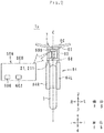
- the upper bracket 66 and the under bracket 68 are, as shown in FIG. 2 , plate-like members extending along the left-right direction lr.
- the upper bracket 66 is positioned farther in the upward direction u than the head pipe 211.
- the under bracket 68 is positioned farther in the downward direction d than the head pipe 211.
- the steering shaft 62 is inserted in the head pipe 211 and thereby is supported by the head pipe 211 in such a manner as to be rotatable. Further, the steering shaft 62 is fixed to the upper bracket 66 and the under bracket 68.
- the handlebar 60 is fixed to the upper bracket 66.
- the front fork 64 is fixed to the upper bracket 66 and the under bracket 68.
- the front fork 64 includes a left shock absorber 64L and a right shock absorber 64R.
- the left shock absorber 64L extends from the upper bracket 66 and the under bracket 68 to the downward direction d.
- the left shock absorber 64L is positioned farther in the leftward direction 1 than the center of the vehicle body frame 21 in an upright posture with respect to the left-right direction lr.
- the right shock absorber 64R extends from the upper bracket 66 and the under bracket 68 in the downward direction d.
- the right shock absorber 64R is positioned farther in the rightward direction r than the center of the vehicle body frame 21 in an upright posture with respect to the left-right direction lr. Accordingly, when the rider turns the handlebar 60, the steering shaft 62, the front fork 64, the upper bracket 66 and the under bracket 68 rotate around the central axis of the steering shaft 62 in a body.
- the left shock absorber 64L and the right shock absorber 64R are what is called telescopic shock absorbers.
- the left shock absorber 64L and the right shock absorber 64R each, for example, include a combination of a damper and a spring.
- the left shock absorber 64L and the right shock absorber 64R expand and contract along the up-down direction ud and thereby absorb displacements of the front wheel 3 along the up-down direction ud.
- the front wheel 3 is a steerable wheel of the leaning vehicle 1a.
- the front wheel 3 is positioned in the front part of the leaning vehicle 1a.
- the front wheel 3 is supported by the lower end part of the front fork 64 in such a manner as to be rotatable around an axle.
- the front wheel 3 is supported by the vehicle body frame 21 via the steering mechanism 7. Accordingly, the rider can steer the front wheel 3 by manipulating the handlebar 60.
- the rear wheel 4 is a driving wheel of the leaning vehicle 1a.
- the rear wheel 4 is rotated by a driving force generated by the power unit 25.
- the rear wheel 4 is positioned in the rear part of the leaning vehicle 1a.
- the rear wheel 4 is supported by the lower end part of the swing arm 26 in such a manner as to be rotatable around an axle.
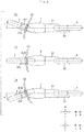
- FIG. 3 is a schematic looking-to-the-down (D) view of the leaning vehicle 1a.
- FIG. 3 shows a state wherein the front wheel 3 is steered in the leftward direction L, a state wherein the front wheel 3 is not steered, and a state wherein the front wheel 3 is steered in the rightward direction R.
- the direction in which the handlebar 60 is turned counterclockwise in a view in the downward direction d is defined as a positive direction.
- the direction in which the handlebar 60 is turned clockwise in a view in the downward direction d is defined as a negative direction.
- the front wheel 3 is turned counterclockwise when the rider turns the handlebar 60 counterclockwise (in the positive direction). Then, the front wheel 3 is steered in the leftward direction L (steered leftward).
- the front wheel 3 is turned clockwise when the rider turns the handlebar 60 clockwise (in the negative direction). Then, the front wheel 3 is steered in the rightward direction R (steered rightward).
- FIG. 4 is a schematic looking-to-the-back (B) view of the leaning vehicle 1a.
- FIG. 4 shows a state wherein the vehicle body frame 21 leans in the leftward direction L and a state wherein the vehicle body frame 21 leans in the rightward direction R.
- FIG. 4 shows that the front wheel 3 is steered leftward by self-steering when the vehicle body frame 21 leans in the leftward direction L.
- FIG. 4 shows that the front wheel 3 is steered rightward by self-steering when the vehicle body frame 21 leans in the rightward direction R.
- the vehicle body frame 21 leans in the leftward direction L or the rightward direction R by rotating around a roll axis Ax.
- the roll axis Ax is an axis extending along the front-back direction FB. More specifically, as shown in FIG. 1B , the roll axis Ax is a straight line that passes the contact point between the rear wheel 4 and the ground and is perpendicular to the steering shaft 62 when the vehicle body frame 21 is in an upright posture. In a view in the backward direction d, the roll axis Ax is in the center of the vehicle body frame 21 in an upright posture with respect to the left-right direction lr.
- the rotation angle of the vehicle body frame 21 around the roll axis Ax changes, and the rotation angle of the vehicle body frame 21 around the roll axis Ax is referred to as a roll angle ⁇ .
- the straight line that passes the center of the vehicle body frame 21 in an upright posture with respect to the left-right direction lr and extends along the up-down direction ud is defined as a center line C.
- the center line C leans in the leftward direction L or the rightward direction R together with the vehicle body frame 21.
- the roll angle ⁇ is an angle formed between the vertical axis and the center line C.
- the vertical axis is an axis parallel to the up-down direction UD.
- the direction of the lean is referred to as a positive direction of the roll angle ⁇ .
- the clockwise direction around the roll axis Ax in a view in the backward direction B is defined as a positive direction of the roll angle ⁇ .
- the direction of the lean is referred to as a negative direction of the roll angle ⁇ .
- the counterclockwise direction around the roll axis Ax in a view in the backward direction B is defined as a negative direction of the roll angle ⁇ .
- the roll angle ⁇ changes within a range of -90° to 90°.
- the vehicle body frame 21 rotates clockwise around the roll axis Ax and leans in the leftward direction L.
- the roll angle ⁇ is a positive value.
- the front wheel 3 is steered leftward by self-steering. Then, the leaning vehicle 1a turns in the leftward direction L.
- the vehicle body frame 21 rotates counterclockwise around the roll axis Ax and leans in the rightward direction R. Also, the front wheel 3 is steered rightward by self-steering. In this case, the roll angle ⁇ is a negative value.
- the leaning vehicle 1a turns in the rightward direction R.
- FIG. 5 is a block diagram of the posture control actuator controller 606.
- the steering torque T is a torque that is generated by the rider's manipulation of the handlebar 60 and acts on the steering shaft 62. More specifically, the steering torque T is a torque that is generated and inputted to the steering shaft 62 by the rider's manipulation of the handlebar 60 when the roll angle ⁇ of the vehicle body frame 21 of the leaning vehicle 1a running at a speed V is changing at a roll rate ⁇ .
- the steering torque T acts around the rotation axis of the handlebar 60 (central axis of the steering shaft 62).
- the direction of the torque is defined as a positive direction of the steering torque T.
- the steering torque T causes a clockwise rotation of the steering shaft 62 in a view in the downward direction d
- the direction of the torque is defined as a negative direction of the steering torque T.
- the leaning vehicle 1a further includes a posture control actuator unit 599 and a speed sensor 604.
- the posture control actuator unit 599 includes an EPS (electric power steering) actuator 600 and a roll rate sensor 602, as well as the posture control actuator controller 606.
- the EPS actuator 600 (an example of a posture control actuator) is supplied with electric power and outputs a posture control torque Tc (an example of posture control power) to cause the steering shaft 62 to rotate on its central axis.
- the posture control torque Tc is a torque to control the posture of the vehicle body frame 21. More specifically, as shown in FIG. 2 , the EPS actuator 600 is fixed in the upper end part of the head pipe 211.
- the EPS actuator 600 is a combination of an electric motor and a gear. The electric motor generates a torque. The torque generated by the electric motor is outputted to the steering shaft 62 as a posture control torque Tc via the gear.
- the roll rate sensor 602 detects the roll rate ⁇ that is the amount of change per unit time of the roll angle ⁇ .
- the direction of the lean is referred to as a positive direction of the roll rate ⁇ .
- the clockwise direction around the roll axis Ax in a view in the backward direction B is defined as a positive direction of the roll rate ⁇ .
- the direction of the lean is referred to as a negative direction of the roll rate ⁇ .
- the counterclockwise direction around the roll axis Ax in a view in the backward direction B is defined as a negative direction of the roll rate ⁇ .
- the speed sensor 604 detects the speed V of the leaning vehicle la.
- the speed V is a positive value when the leaning vehicle 1a is running forward.
- the posture control actuator controller 606 controls the EPS actuator 600 based on the roll rate ⁇ detected by the roll rate sensor 602.
- the posture control actuator controller 606 is, for example, an IC (integrated circuit) for control of the EPS actuator 600.
- the posture control actuator controller 606 does not need to be achieved by a single IC, and the posture control actuator controller 606 may be a combination of one or more ICs, one or more electronic components and/or one or more circuit boards.
- the EPS actuator 600, the roll rate sensor 602 and the posture control actuator controller 606 are incorporated in such a manner as not to be displaceable relative to one another, and the posture control actuator unit 599 is supported by the vehicle body frame 21 in such a manner as to be attachable to and detachable from the vehicle body frame 21. More specifically, for example, the roll rate sensor 602 and the posture control actuator controller 606 are fixed in a case of the EPS actuator 600 as shown in FIG. 2 .
- the means for fixing the roll rate sensor 602 and the posture control actuator controller 606 to the EPS actuator 600 may be a combination of a bolt and a nut, a screw, a snap-fit, an adhesive, an adhesive tape, welding, brazing, etc.
- the EPS actuator 600 is to output a posture control torque Tc to the steering shaft 62. Therefore, the EPS actuator 600 is supported by the vehicle body frame 21 in such a manner as not to be displaceable relative to the vehicle body frame 21. In this structure, the roll rate sensor 602 and the posture control actuator controller 606 are not displaceable relative to the EPS actuator 600, and the EPS actuator 600 is not displaceable relative to the vehicle body frame 21.
- a first member is supported by a second member in such a manner as not to be displaceable relative to the second member, it also means that there is no elastic member for impact absorption, such as a rubber mount or the like, between the first member and the second member.
- the EPS actuator 600 is fixed in the upper end part of the head pipe 211. Therefore, in a view in the backward direction d, the EPS actuator 600 overlaps the center line C. Accordingly, in a view in the backward direction d, the posture control actuator unit 599 overlaps the center line C. In the leaning vehicle 1a, in a view in the backward direction d, the roll rate sensor 602 overlaps the center line C.
- the posture control actuator controller 606 obtains the roll rate ⁇ from the roll rate sensor 602. Specifically, an electric signal representing the roll rate ⁇ (which will hereinafter be referred to simply as roll rate ⁇ ) detected by the roll rate sensor 602 is inputted to the posture control actuator controller 606.
- the posture control actuator controller 606 obtains the speed V from the speed sensor 604. Specifically, an electric signal representing the speed V (which will hereinafter be referred to simply as speed V) detected by the speed sensor 606 is inputted to the posture control actuator controller 606.
- the posture control actuator controller 606 does not use a torque sensor that detects the steering torque T that is generated by the rider's manipulation of the handlebar 60 and acts around the rotation axis (central axis of the steering shaft 62), and uses the roll rate sensor 602. Then, the posture control actuator controller 606 controls the EPS actuator 600 not based on the steering torque T that is generated by the rider's manipulation of the handlebar 60 and acts around the rotation axis (central axis of the steering shaft 62), but based on the roll rate ⁇ sent from the roll rate sensor 602. In the present embodiment, the posture control actuator controller 606 uses neither a torque sensor that detects the steering torque T nor a roll sensor that detects the roll angle ⁇ .
- the posture control actuator controller 606 uses the roll rate sensor 602 and the speed sensor 604. Then, the posture control actuator controller 606 controls the EPS actuator 600 based on neither the steering torque T detected by a torque sensor nor the roll angle ⁇ detected by a roll sensor. The posture control actuator controller 606 controls the EPS actuator 600 based on the roll rate ⁇ sent from the roll rate sensor 602 and the speed V sent from the speed sensor 604.
- the statement that the posture control actuator controller 606 uses neither a torque sensor nor a roll sensor means, for example, that the posture control actuator controller 606 does not use signals sent from a torque sensor and a roll sensor for control.
- the statement that the posture control actuator controller 606 uses the roll rate sensor 602 and the speed sensor 604 means, for example, that the posture control actuator controller 606 uses signals sent from the roll rate sensor 602 and the speed sensor 604 for control.
- the posture control actuator controller 606 includes a torque estimation section 614 and a current determination section 616.
- the torque estimation section 614 determines an estimated steering torque value T(m, n), which is an estimated value of the steering torque T, based on the speed V and the roll rate ⁇ .
- the values m and n are integers.
- the estimated steering torque value T(m, n) is a value of the steering torque T that is estimated to be inputted to the steering shaft 62 by the rider's manipulation of the handlebar 60 when the roll angle ⁇ of the vehicle body frame 21 is changing at a roll rate ⁇ while the leaning vehicle 1a is running at a speed V.
- the torque estimation section 614 stores an estimated torque determination table as shown by TABLE 1.
- values of the estimated steering torque T(m, n) are stored in association with values of the speed V(m) and values of the roll rate ⁇ (n).
- the values of the speed V(m) are greater than 0 km/h.
- the roll rate ⁇ (n) is a positive value. In this case, the greater the value n is, the greater the roll rate ⁇ (n) is. On the other hand, when the value n is negative, the roll rate ⁇ (n) is a negative value. In this case, the greater the value n is, the smaller the roll rate ⁇ (n) is (the greater the absolute value of the roll rate ⁇ (n) is). Accordingly, ⁇ (n) ⁇ ⁇ (n+1) holds.
- While the leaning vehicle 1a is running forward, when the rider turns the handlebar 60 clockwise (in the negative direction), the front wheel 3 is rotated at a roll rate ⁇ (n) of a positive value.
- the front wheel 3 is rotated at a roll rate ⁇ (n) of a positive value.
- the vehicle body 21 is in an upright posture, when the rider turns the handlebar 60 clockwise (in the negative direction), the front wheel 3 is steered rightward. Then, the vehicle body frame 21 leans in the leftward direction L.
- the leaning vehicle 1a is running forward, when the rider turns the handlebar 60 counterclockwise (in the positive direction), the front wheel 3 is rotated at a roll rate ⁇ (n) of a negative value.
- the estimated steering torque T(m, n) has the following relationship with the values m and n.
- the estimated steering torque T(m, n) When the value n is positive (when the roll rate ⁇ (n) is a positive value), the estimated steering torque T(m, n) is a negative value. In this case, the estimated steering torque T(m, n) indicates a steering torque to cause the steering shaft 62 to rotate clockwise (in the negative direction) in a view in the downward direction d.
- the greater the value m is (the greater the speed V(m) is), the smaller the estimated steering torque T(m, n) is (the greater the absolute value of the estimated steering torque T(m, n) is).
- the estimated steering torque T(m, n) when the value n is negative (when the roll rate ⁇ (n) is a negative value), the estimated steering torque T(m, n) is a positive value.
- the estimated steering torque T(m, n) indicates a steering torque to cause the steering shaft 62 to rotate counterclockwise (in the positive direction) in a view in the downward direction d.
- the greater the value m is (the greater the speed V(m) is), the greater the estimated steering torque T(m, n) is.
- the torque estimation section 614 identifies a speed V(m) that is closest to the speed V that the posture control actuator controller 606 has obtained. Also, the torque estimation section 614 identifies a roll rate ⁇ (n) that is closest to the roll rate ⁇ that the posture control actuator controller 606 has obtained. Then, the torque estimation section 614 determines an estimated steering torque T(m, n) in association with the speed value V(m) and the roll rate ⁇ (n) with reference to TABLE 1.
- the current determination section 616 controls the EPS actuator 600 based on the estimated steering torque T(m, n) determined by the torque estimation section 614. Specifically, the current determination section 616 determines a control current I(m, n) to be outputted to the EPS actuator 600, based on the estimated steering torque T(m, n). For this purpose, the current determination section 616 stores a control current determination table as shown by TABLE 2.
- the control current I(m, n) is a current that the EPS actuator 600 requires to output a posture control torque Tc corresponding to the assist rate (for example, 20%) of the estimated steering torque T(m, n) to the steering shaft 62.
- the EPS actuator 600 outputs a posture control torque Tc corresponding to 20% of the estimated steering torque T(m, n) to the steering shaft 62. Accordingly, the rider only needs to manipulate the handlebar 60 to apply 80% of the estimated steering torque T(m, n) to the steering shaft 62.
- the ESP actuator 600 assists the rider's manipulation of the handlebar 60.
- the assist rate is an arbitrary value and may be a value other than 20%. In order to allow the rider to manipulate the handlebar 60 with less power, the assist rate should be more than 20%. In order to allow the rider to manipulate the handlebar 60 with more power, the assist rate should be less than 20%. The assist rate may be a negative value.
- the EPS actuator 600 outputs a posture control steering torque Tc to inhibit the rider's manipulation of the handlebar 60. Then, the EPS actuator 600 functions as a steering damper.
- the control current I(m, n) When the value n is positive, the control current I(m, n) is a negative value. The greater the value n is, the smaller the control current I(m, n) is (the greater the absolute value of the control current I(m, n) is). Also, the greater the value m is, the smaller the control current I(m, n) is (the greater the absolute value of the control current I(m, n) is).
- the control current I(m, n) is a positive value.
- the EPS actuator 600 outputs a posture control torque Tc to the steering shaft 62 by the control current I(m, n) outputted from the current determination section 616.
- the current determination section 616 does not need to output the control current I(m, n) to the EPS actuator 600 directly.
- the control current I(m, n) may be supplied to the EPS actuator 600 from a power source that is provided separately from the posture control actuator controller 606.
- the EPS actuator 600 When receiving a negative control current I(m, n), the EPS actuator 600 outputs a posture control torque Tc to rotate the steering shaft 62 clockwise (in the negative direction).
- the vehicle body frame 21 rotates clockwise (in the positive direction) around the roll axis Ax at a roll rate ⁇ .
- the EPS actuator 600 when receiving a positive control current I(m, n), the EPS actuator 600 outputs a posture control torque Tc to rotate the steering shaft 62 counterclockwise (in the positive direction).
- the vehicle body frame 21 rotates counterclockwise (in the negative direction) around the roll axis Ax at a roll rate ⁇ .
- the posture control actuator controller 606 controls the EPS actuator 606 to output a posture control torque Tc, based on the speed V and the roll rate ⁇ . Then, the steering shaft 62 rotates, and the vehicle body frame 21 rotates clockwise or counterclockwise around the roll axis Ax in a view in the backward direction B. Accordingly, the posture of the vehicle body frame 21 changes. In this way, the posture control actuator controller 606 controls the posture of the vehicle body frame 21 based on the speed V and the roll rate ⁇ .
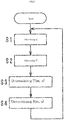
- FIG. 6 is a flowchart showing operations performed by the posture control actuator controller 606.
- the posture control actuator controller 606 performs a process that will be described below along a software program stored in a storage device (not shown).
- the process is started when an ignition source of the leaning vehicle 1a is turned on. As long as the ignition source is on, the roll rate sensor 602 keeps outputting the roll rate ⁇ to the posture control actuator controller 606. Also, the speed sensor 604 keeps outputting the speed V to the posture control actuator controller 606.
- the torque estimation section 614 obtains the roll rate ⁇ from the roll rate sensor 602 (step S1). Further, the torque estimation section 614 obtains the speed V from the speed sensor 604 (step S2).
- the torque estimation section 614 identifies one of the roll rate values listed in the estimation steering torque table as shown in TABLE 1 as a roll rate ⁇ (n) closest to the roll rate ⁇ . Further, the torque estimation section 614 identifies one of the speed values listed in the estimation steering torque table as shown by TABLE 1 as a speed V(m) closest to the speed V. Then, the torque estimation section 614 determines an estimated steering torque T(m, n) in association with the roll rate ⁇ (n) and the speed V(m) with reference to the estimation steering torque table as shown by TABLE 1 (step S3).
- the current determination section 616 determines a control current I(m, n) corresponding to the estimated steering torque T(m, n) determined by the torque estimation section 614 by using the control current determination table as shown by TABLE 2 (step S4).
- the current determination section 616 outputs the control current I(m, n) to the EPS actuator 600.
- the EPS actuator 600 outputs a posture control torque Tc corresponding to the control current I(m, n) to the steering shaft 62. Thereafter, the process returns to step S1.
- the process from step S1 to S4 is repeated until the ignition source is switched from on to off.
- the roll rate sensor 602 of the posture control actuator unit 599 can detect a posture change of the vehicle body frame 21 with high accuracy. More specifically, the EPS actuator 600 outputs posture control power to control the posture of the vehicle body frame 21.
- the posture control actuator unit 599 is supported by the vehicle body frame 21 in such a manner as to be attachable to and detachable from the vehicle body frame 21. Accordingly, a posture change of the EPS actuator 600 is unlikely to delay relative to a posture change of the vehicle body frame 21.
- the EPS actuator 600 and the roll rate sensor 602 are incorporated in such a manner as not to be displaceable relative to each other. Accordingly, a posture change of the roll rate sensor 602 is unlikely to delay relative to a posture change of the vehicle body frame 21. Therefore, the roll rate sensor 602 of the posture change actuator unit 599 can detect a posture change of the vehicle body frame 21 with high accuracy.
- the roll rate sensor 602 of the posture control actuator unit 599 can detect a posture change of the vehicle body frame 21 with high accuracy. More specifically, the EPS actuator 600 outputs posture control power to control the posture of the vehicle body frame 21.
- the EPS actuator 600 is designed to be positioned at a predetermined angle to the roll axis Ax or the like that is associated with a posture change of the vehicle body frame 21.
- the EPS actuator 600 may be positioned such that its rotation axis is parallel to the steering shaft.
- the EPS actuator 600 is attached to the vehicle body frame 21 with high positional accuracy.
- the EPS actuator 600 and the roll rate sensor 602 are incorporated in such a manner as not to be displaceable relative to each other. Accordingly, the roll rate sensor 602 is attached to a sensor mounting position of the vehicle body frame 21 with high accuracy. Therefore, the roll rate sensor 602 of the posture control actuator unit 599 can detect a posture change of the vehicle body frame 21 with high accuracy.
- the roll rate sensor 602 of the posture control actuator unit 599 can detect the roll rate of the vehicle body frame 21 with high accuracy also for the following reason. More specifically, the posture control actuator unit 599 is positioned to overlap the center line C in a view in the backward direction b.
- the roll rate sensor 602 is included in the posture control actuator unit 599. Accordingly, the roll rate sensor 602 is positioned near the center line C in a view in the backward direction b. Accordingly, the roll rate sensor 602 of the posture control actuator unit 599 can detect the roll rate ⁇ with high accuracy. Since the roll rate sensor 602 can detect the roll rate ⁇ with high accuracy, the posture control actuator controller 606 can accurately control the posture of the vehicle body frame 21 through the EPS actuator 600.
- the EPS actuator 600 of the posture control actuator unit 599 is attached to the vehicle body frame 21 with high positional accuracy. Accordingly, it is easy to make the axis for the roll rate detection carried out by the roll rate sensor 602 almost parallel to the roll axis Ax of the vehicle body frame 21. Then, the roll rate sensor 602 can detect the roll rate of the vehicle body frame 21 with high accuracy. Even when the axis for the roll rate detection carried out by the roll rate sensor 602 is not parallel to the roll axis Ax of the vehicle body frame 21, it is easy to identify the angle formed between the axis for the roll rate detection carried out by the roll rate sensor 602 and the roll axis Ax of the vehicle body frame 21. Accordingly, it is easy to make a correction to the roll rate detected by the roll rate sensor 602.
- the posture control actuator unit 599 can be downsized. More specifically, in the posture control actuator unit 599, the EPS actuator 600 and the roll rate sensor 602 are incorporated in such a manner as not to be displaceable relative to each other. Accordingly, it is not necessary to provide a mount for attachment of the roll rate sensor 602 to the vehicle body frame 21. Therefore, the number of components of the posture control actuator unit 599 can be reduced, and the posture control actuator unit 599 can be downsized.
- the posture control actuator controller 606 of the posture control actuator unit 599 controls the rotation of the steering shaft 62 based on the roll rate ⁇ of the vehicle body frame 21 accurately detected by the roll rate sensor 602.
- the posture control actuator controller 606 of the posture control actuator unit 599 can control the posture of the vehicle body frame 21 accurately.
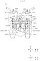
- FIG. 7 is a looking-to-the-right (r) view of the leaning vehicle 1b when the vehicle body frame 21 is in an upright posture.
- FIG. 8 is a looking-to-the-back (b) view of the front part of the leaning vehicle 1b when the vehicle body frame 21 is in an upright posture.
- the vehicle body cover 22 is shown as being transparent.
- the leaning vehicle 1b includes a vehicle body 1002, a left front wheel 1031, a right front wheel 1032 (see FIG. 8 ), a rear wheel 1004, a link mechanism 1005, and a steering mechanism 1007.
- the vehicle body 1002 includes a vehicle body frame 1021, a vehicle body cover 1022, a seat 1024, and a power unit 1025.
- the vehicle body frame 1021 leans in the leftward direction L when the leaning vehicle 1b is turning left.
- the vehicle body frame 1021 leans in the rightward direction R when the leaning vehicle 1b is turning right.
- the vehicle body frame 1021 includes a head pipe 1211, a down frame 1212, an underframe 1214, and a rear frame 1215.
- the part of the vehicle body frame 1021 behind the vehicle body cover 1022 is indicated by a chain line.
- the vehicle body frame 1021 supports the seat 1024, the power unit 1025, etc.
- the head pipe 1211 is positioned in the front part of the leaning vehicle 1b.
- the front part of the leaning vehicle 1b is a part thereof that is farther in the forward direction f than the front edge of the seat 1024.
- the rear part of the leaning vehicle 1b is a part thereof that is farther in the backward direction b than the front edge of the seat 1024.
- the head pipe 1211 is inclined from the up-down direction ud such that the upper end part of the head pipe 1211 is positioned farther in the backward direction b than the lower end part of the head pipe 1211 in a view in the leftward direction 1 or the rightward direction r.
- the down frame 1212 is positioned farther in the backward direction b than the head pipe 1211.
- the down frame 1212 is a cylindrical member extending along the up-down direction ud.
- the upper end part of the down frame 1212 is positioned farther in the backward direction b than the head pipe 1211 in a view in the rightward direction r.
- the down frame 1212 extends from the upper end part of the down frame 1212 to the downward direction d.
- the upper end part of the down frame 1212 is fixed to the lower end part of the head pipe 1211 via a connecting part (not shown).
- the underframe 1214 extends from the lower end part of the down frame 1212 to the backward direction b.
- the rear frame 1215 linearly extends from the rear edge of the underframe 1214 to a backward and upward direction b, u.
- the vehicle body frame 1021 is covered by the vehicle body cover 1022.
- the vehicle body cover 1022 includes a front cover 1221, a pair of right and left front fenders 1223, and a leg shield 1225.
- the front cover 1221 is positioned farther in the forward direction f than the seat 1024.
- the front cover 1221 covers at least some part of the steering mechanism 1007 and the link mechanism 1005.
- the power unit 1025 includes a power source, such as an engine, an electric motor or the like, and a power transmission system, such as a transmission device or the like.
- a power source such as an engine, an electric motor or the like
- a power transmission system such as a transmission device or the like.
- the seat 1024 is to be sat on by a rider.
- the seat 1024 is supported by the rear frame 1215.
- the left front wheel 1031 is a left steerable wheel of the leaning vehicle 1b.
- the left front wheel 1031 is positioned in the front part of the leaning vehicle 1b. As shown in FIG. 8 , the left front wheel 1031 is positioned farther in the leftward direction 1 than the center of the vehicle body frame 1021 with respect to the left-right direction lr.
- the left front wheel 1031 is rotatable around a left front axle 1314 (an example of an axle of a left steerable wheel).
- the right front wheel 1032 is a right steerable wheel of the leaning vehicle 1b.
- the right front wheel 1032 is positioned in the front part of the leaning vehicle 1b. As shown in FIG. 8 , the right front wheel 1032 is positioned farther in the rightward direction r than the center of the vehicle body frame 1021 with respect to the left-right direction lr.
- the right front wheel 1032 is rotatable around a right front axle 1324 (an example of an axle of a right steerable wheel).
- the left front wheel 1031 and the right front wheel 1032 are arranged lateral-symmetrically with respect to the center.
- the pair of front fenders 1223 includes a left front fender 1227 and a right front fender 1228.
- the left front fender 1227 is positioned farther in the upward direction u than the left front wheel 1031.
- the right front fender 1228 is positioned farther in the upward direction u than the right front wheel 1032.
- the rear wheel 1004 is a driving wheel of the leaning vehicle 1b.
- the rear wheel 1004 is rotated by a driving force generated by the power unit 1025.
- the rear wheel 1004 is positioned in the rear part of the leaning vehicle 1b.
- the rear wheel 1004 is rotatable around an axle.
- FIG. 9 is a looking-to-the-down (d) view of the front part of the leaning vehicle 1b when the vehicle body frame 1021 is in an upright posture.
- the vehicle body cover 1022 is shown as being transparent.
- the steering mechanism 1007 is configured to steer the left front wheel 1031 and the right front wheel 1032 in accordance with the rider's manipulation. As shown in FIGS. 8 and 9 , the steering mechanism 1007 includes a left shock absorber 1033, a right shock absorber 1034, a handlebar 1060, a steering shaft 1062, a tie rod 1067, a left bracket 1317, a right bracket 1327, and a center bracket 1337.
- the left shock absorber 1033 supports the left front wheel 1031 such that the left front wheel 1031 is movable along the up-down direction ud relative to the vehicle body frame 1021.
- the left shock absorber 1033 includes a left lower portion 1033a, a left upper portion 1033b, and a left support portion 1033c.
- the left lower portion 1033a extends along the up-down direction ud.
- the left support portion 1033c is positioned in the lower end part of the left lower portion 1033a.
- the left support portion 1033c supports the left front wheel 1031 such that the left front wheel 1031 is rotatable.
- the left front wheel 1031 is rotatable around the left front axle 1314.
- the left front axle 1314 extends from the left support portion 1033c to the leftward direction 1.
- the left upper portion 1033b extends along the up-down direction ud.
- the left upper portion 1033b is positioned farther in the upward direction u than the left lower portion 1033a with the lower end part thereof inserted in the left lower portion 1033a.
- the upper end part of the left upper portion 1033b is fixed to the left bracket 1317, which will be described later. Accordingly, the left upper portion 1033b is supported by a left side member 1053, which will be described later.
- the left shock absorber 1033 is what is called a telescopic shock absorber.
- the left shock absorber 1033 for example, includes a combination of a damper and a spring.
- the left upper portion 1033b moves relative to the left lower portion 1033a in the extending direction of the left lower portion 1033a, and accordingly, the left shock absorber 1033 is expandable in the direction. In this way, the left shock absorber 1033 absorbs displacements of the left front wheel 1031 in the up-down direction ud relative to the left upper portion 1033b.
- the right shock absorber 1034 supports the right front wheel 1032 such that the right front wheel 1032 is movable along the up-down direction ud relative to the vehicle body frame 1021.
- the right shock absorber 1034 includes a right lower portion 1034a, a right upper portion 1034b, and a right support portion 1034c.
- the right lower portion 1034a extends along the up-down direction ud.
- the right support portion 1034c is positioned in the lower end part of the right lower portion 1034a.
- the right support portion 1034c supports the right front wheel 1032 such that the right front wheel 1032 is rotatable.
- the right front wheel 1032 is rotatable around the right front axle 1324.
- the right front axle 1324 extends from the right support portion 1034c to the rightward direction r.
- the right upper portion 1034b extends along the up-down direction ud.
- the right upper portion 1034b is positioned farther in the upward direction u than the right lower portion 1034a with the lower end part thereof inserted in the right lower portion 1034a.
- the upper end part of the right upper portion 1034b is fixed to the right bracket 1327, which will be described later. Accordingly, the right upper portion 1034b is supported by a right side member 1054, which will be described later.
- the right shock absorber 1034 is what is called a telescopic shock absorber.
- the right shock absorber 1034 for example, includes a combination of a damper and a spring.
- the right upper portion 1034b moves relative to the right lower portion 1034a in the extending direction of the right lower portion 1034a, and accordingly, the right shock absorber 1034 is expandable in the direction. In this way, the right shock absorber 1034 absorbs displacements of the right front wheel 1032 in the up-down direction ud relative to the right upper portion 1034b.
- the handlebar 1060 is to be manipulated by the rider.
- the steering shaft 1062 is supported by the vehicle body frame 1021 in such a manner as to be rotatable on its central axis in accordance with the rider's manipulation of the handlebar 1060. More specifically, the steering shaft 1062 is inserted in the head pipe 1211 and thereby is supported by the head pipe 1211 in such a manner as to be rotatable.
- the handlebar 1060 is fixed to the upper end part of the steering shaft 1062. Then, when the rider manipulates the handlebar 1060, the steering shaft 1062 rotates on its central axis.
- the center bracket 1337 is fixed to the lower end part of the steering shaft 1062. Accordingly, the center bracket 1337 is rotatable around the central axis of the steering shaft 1062 together with the steering shaft 1062.
- the tie rod 1067 transmits the rotation of the steering shaft 1062 caused by the rider's manipulation of the handlebar 1060 to the left shock absorber 1033 and the right shock absorber 1034.
- the tie rod 1067 extends along the left-right direction LR.
- the center of the tie rod 1067 with respect to the left-right direction LR is supported by the center bracket 1337.
- the left end part of the tie rod 1067 is supported by the left bracket 1317.
- the right end part of the tie rod 1067 is supported by the right bracket 1327.
- the link mechanism 1005 will hereinafter be described with reference to FIGS. 8 and 9 .
- the link mechanism 1005 is a parallelogram link mechanism.
- the link mechanism 1005 is positioned farther in the downward direction d than the handlebar 1060.
- the link mechanism 1005 is supported by the head pipe 1211 of the vehicle body frame 1021.
- the link mechanism 1005 includes an upper cross member 1051, a lower cross member 1052, a left side member 1053 and a right side member 1054.
- the upper cross member 1051, the lower cross member 1052, the left side member 1053 and the right side member 1054 are link members that are displaceable relative to the vehicle body frame 1021.
- a displacement includes a displacement by translation, a displacement by rotation, and a displacement by combination of translation and rotation.
- the upper cross member 1051 extends along the left-right direction LR.
- the upper cross member 1051 is positioned farther in the forward direction f than the head pipe 1211 and farther in the upward direction u than the left front wheel 1031 and the right front wheel 1032.
- the upper cross member 1051 is supported by the head pipe 1211 via a support C.
- the support C is positioned in a middle part of the upper cross member 1051 and in the upper part of the head pipe 1211.
- the part positioned farthest in the rightward direction R of the three parts is a right part of the upper cross member 1051.
- the middle part of the upper cross member 1051 is the part positioned in the middle of the three parts.
- the support C is a shaft extending along the front-back direction fb.
- the support C extends from the head pipe 1211 to the forward direction f, slightly inclined to the upward direction u.
- the upper cross member 1051 is rotatable around the support C and accordingly rotatable relative to the head pipe 1211.
- the lower cross member 1052 includes a front lower cross member 1052A and a rear lower cross member 1052B.
- the front lower cross member 1052A extends along the left-right direction LR.
- the front lower cross member 1052A is positioned farther in the forward direction f than the head pipe 1211, farther in the downward direction u than the upper cross member 1051, and farther in the upward direction u than the left front wheel 1031 and the right front wheel 1032.
- the front lower cross member 1052A is supported by the head pipe 1211 via a support F.
- the support F is positioned in a middle part of the front lower cross member 1052A and in the lower part of the head pipe 1211.
- the part positioned farthest in the leftward direction L of the three parts is a left part of the front lower cross member 1052A.
- the part positioned farthest in the rightward direction R of the three parts is the right part of the front lower cross member 1052A.
- the middle part of the front lower cross member 1052A is the part positioned in the middle of the three parts.
- the support F is a shaft extending along the front-back direction fb.
- the support F extends from the head pipe 1211 to the forward direction f, slightly inclined to the upward direction u.
- the front lower cross member 1052A is rotatable around the support F and accordingly rotatable relative to the head pipe 1211.
- the rear lower cross member 1052B extends along the left-right direction LR.
- the rear lower cross member 1052B is positioned farther in the backward direction b than the head pipe 1211, farther in the downward direction u than the upper cross member 1051, and farther in the upward direction u than the left front wheel 1031 and the right front wheel 1032.
- the rear lower cross member 1052B is supported by the head pipe 1211 via the support F.
- the support F is positioned in a middle part of the rear lower cross member 1052B and in the lower part of the head pipe 1211.
- the part positioned farthest in the rightward direction R of the three parts is a right part of the rear lower cross member 1052B.
- the middle part of the rear lower cross member 1052B is the part positioned in the middle of the three parts.
- the support F is a shaft extending along the front-back direction fb.
- the support F extends from the head pipe 1211 also to the backward direction b, slightly inclined to the downward direction u.
- the rear lower cross member 1052B is rotatable around the support F and accordingly rotatable relative to the head pipe 1211.
- the left side member 1053 extends along the up-down direction ud. Accordingly, the extending direction of the left side member 1053 is parallel to the extending direction of the head pipe 1211. The left side member 1053 is positioned farther in the leftward direction 1 than the head pipe 1211. The left side member 1053 is positioned farther in the upward direction u than the left front wheel 1031 and farther in a left-upward direction lu than the left shock absorber 1033.
- the left side member 1053 is supported by the upper cross member 1051 via a support D.
- the support D is positioned in the upper part of the left side member 1053 and in the left part of the upper cross member 1051.
- the support D is a shaft extending along the front-back direction fb.
- the left side member 1053 is rotatable around the support D and accordingly rotatable relative to the upper cross member 1051.
- the left side member 1053 is supported by the front lower cross member 1052A and the rear lower cross member 1052B via a support G.
- the support G is positioned in the lower part of the left side member 1053, in the left part of the front lower cross member 1052A and in the left part of the rear lower cross member 1052B.
- the support G is a shaft extending along the front-back direction fb.
- the left side member 1053 is rotatable around the support G and accordingly rotatable relative to the front lower cross member 1052A and the rear lower cross member 1052B.
- the left bracket 1317 is supported by the lower end part of the left side member 1053.
- the left bracket 1317 is rotatable around a left central axis Y1 and rotatable relative to the left side member 1053.
- the left central axis Y1 is a central axis of the left side member 1053.
- the left central axis Y1 extends along the up-down direction ud.
- the right side member 1054 extends along the up-down direction ud. Accordingly, the extending direction of the right side member 1054 is parallel to the extending direction of the head pipe 1211. The right side member 1054 is positioned farther in the rightward direction r than the head pipe 1211. The right side member 1054 is positioned farther in the upward direction u than the right front wheel 1032 and farther in a right-upward direction ru than the right shock absorber 1034.
- the right side member 1054 is supported by the upper cross member 1051 via a support E.
- the support E is positioned in the upper part of the right side member 1054 and in the right part of the upper cross member 1051.
- the support E is a shaft extending along the front-back direction fb.
- the right side member 1054 is rotatable around the support E and accordingly rotatable relative to the upper cross member 1051.
- the right side member 1054 is supported by the front lower cross member 1052A and the rear lower cross member 1052B via a support H.
- the support H is positioned in the lower part of the right side member 1054 and in the right part of the front lower cross member 1052A and in the right part of the rear lower cross member 1052B.
- the support H is a shaft extending along the front-back direction fb.
- the right side member 1054 is rotatable around the support H and accordingly rotatable relative to the front lower cross member 1052A and the rear lower cross member 1052B.
- the right bracket 1327 is supported by the lower end part of the right side member 1054.
- the right bracket 1327 is rotatable around a right central axis Y2 and rotatable relative to the right side member 1054.
- the right central axis Y2 is a central axis of the right side member 1054.
- the right central axis Y2 extends along the up-down direction ud.
- the upper cross member 1051, the lower cross member 1052, the left side member 1053 and the right side member 1054 are connected to one another such that the upper cross member 1051 and the lower cross member 1052 are kept parallel to each other and such that the left side member 1053 and the right side member are kept parallel to each other.
- the left shock absorber 1033 is positioned farther in a right-downward direction rd than the left side member 1053.
- the left shock absorber 1033 is supported by the left bracket 1317. Specifically, the upper end part of the left shock absorber 1033 is fixed to the left bracket 1317. Further, the left shock absorber 1033 supports the left front wheel 1031. Accordingly, the left side member 1053 supports the left front wheel 1031 via the left bracket 1317 and the left shock absorber 1033. In this way, the link mechanism 1005 supports the left front wheel 1031.
- the left shock absorber 1033 leans in the left-right direction LR together with the left side member 1053.
- the right shock absorber 1034 is positioned farther in a left-downward direction ld than the right side member 1054.
- the right shock absorber 1034 is supported by the right bracket 1327. Specifically, the upper end part of the right shock absorber 1034 is fixed to the right bracket 1327. Further, the right shock absorber 1034 supports the right front wheel 1032. Accordingly, the right side member 1054 supports the right front wheel 1032 via the right bracket 1327 and the right shock absorber 1034. In this way, the link mechanism 1005 supports the right front wheel 1032.
- the right shock absorber 1034 leans in the left-right direction LR together with the right side member 1054.
- FIG. 10 is a looking-to-the-down (d) view of the front part of the leaning vehicle 1b when the leaning vehicle 1b is steered leftward.
- the steering shaft 1062 rotates counterclockwise in a view in the downward direction d. Since the center bracket 1337 is fixed to the lower end part of the steering shaft 1062, the center bracket 1337 rotates counterclockwise in a view in the downward direction d together with the steering shaft 1062.
- the tie rod 1067 makes a parallel translation in a backward and leftward direction 1, b with the rotation of the center bracket 1337.
- the left end part of the tie rod 1067 is supported by the front end part of the left bracket 1317.
- the left bracket 1317 is rotatable around the left central axis Y1 (see FIG. 8 ). Accordingly, with the parallel translation of the tie rod 1067, the left bracket 1317 rotates counterclockwise in a view in the downward direction d.
- the right end part of the tie rod 1067 is fixed to the front end part of the right bracket 1327.
- the right bracket 1327 is rotatable around the right central axis Y2 (see FIG. 8 ). Accordingly, with the parallel translation of the tie rod 1067, the right bracket 1327 rotates counterclockwise in a view in the downward direction d.
- the left front wheel 1031 is connected to the left bracket 1317 via the left shock absorber 1033. Therefore, with the rotation of the left bracket 1317, the left front wheel 1031 rotates counterclockwise around the left central axis Y1 (see FIG. 2 ) in a view in the downward direction d.
- the right front wheel 1032 is connected to the right bracket 1327 via the right shock absorber 1034. Therefore, with the rotation of the right bracket 1327, the right front wheel 1327 rotates counterclockwise around the right central axis Y2 (see FIG. 8 ) in a view in the downward direction d.
- each of the elements described above rotates in a direction opposite to the direction of rotation when the rider steers the handlebar 1060 leftward (that is, rotates clockwise).
- the motion of each of the elements is laterally reversed, and no more description will be provided.
- FIG. 11 is a looking-to-the-back (b) view of the front part of the leaning vehicle 1b when the vehicle body frame 1021 leans in the leftward direction L.
- the vehicle body frame 1021 rotates around the roll axis Ax and thereby leans in the leftward direction L or the rightward direction R.
- the roll axis Ax is an axis extending along the front-back direction FB. More specifically, as shown in FIG. 7 , the roll axis Ax is a straight line that passes the contact point between the rear wheel 1004 and the ground, and is perpendicular to the steering shaft 1062 when the vehicle body frame 1021 is in an upright posture.
- the roll angle ⁇ of the leaning vehicle 1b is the same as the roll angle ⁇ of the leaning vehicle 1a, and the description is omitted.
- the upper cross member 1051, the lower cross member 1052, the left side member 1053 and the right side member 1054 of the link mechanism 1005 displace relative to the vehicle body frame 1021 such that the left front axle 1314 is positioned farther in the upward direction u than the right front axle 1324, and thereby, the vehicle body frame 1021 is caused to lean in the leftward direction L.
- the roll angle ⁇ is a positive value.
- the upper cross member 1051, the lower cross member 1052, the left side member 1053 and the right side member 1054 of the link mechanism 1005 displace relative to the vehicle body frame 1021, such that the right front axle 1324 is positioned farther in the upward direction u than the left front axle 1314, and thereby, the vehicle body frame 1021 is caused to lean in the rightward direction R.
- the roll angle ⁇ is a negative value.
- the vehicle body frame 1021 is changed from an upright posture to a leaning posture in the leftward direction L by a shape change of the link mechanism 1005.
- the upper cross member 1051, the lower cross member 1052, the left side member 1053 and the right side member 1054 form a rectangle in the leaning vehicle 1b.
- the upper cross member 1051, the lower cross member 1052, the left side member 1053 and the right side member 1054 form a parallelogram in the leaning vehicle 1b.
- the head pipe 1211 leans in the leftward direction L.
- the upper cross member 1051 rotates around the support C in such a manner as to rotate counterclockwise relative to the head pipe 1211 in a view in the backward direction b.
- the lower cross member 1052 rotates around the support F in such a manner as to rotate counterclockwise relative to the head pipe 1211 in a view in the backward direction b.
- the upper cross member 1051 moves in the leftward direction L relative to the lower cross member 1052.
- the left side member 1053 rotates around the support D in such a manner as to rotate clockwise relative to the upper cross member 1051 in a view in the backward direction b.
- the right side member 1054 rotates around the support E in such a manner as to rotate clockwise relative to the upper cross member 1051 in a view in the backward direction b.
- the left side member 1053 rotates around the support G in such a manner as to rotate clockwise relative to the lower cross member 1052 in a view in the backward direction b.
- the right side member 1054 rotates around the support H in such a manner as to rotate clockwise relative to the lower cross member 1052 in a view in the backward direction b. In this way, the left side member 1053 and the right side member 1054 lean in the leftward direction L while being kept parallel to the head pipe 1211.
- the left bracket 1317 is supported by the lower end part of the left side member 1053. Therefore, when the left side member 1053 leans in the leftward direction L, the left bracket 1317 leans in the leftward direction L.
- the left shock absorber 1033 is supported by the left bracket 1317, and therefore, when the left bracket 1317 leans in the leftward direction L, the left shock absorber 1033 leans in the leftward direction L.
- the left front wheel 1031 is supported by the lower end part of the left shock absorber 1033, and therefore, when the left shock absorber 1033 leans in the leftward direction L, the left front wheel 1031 leans in the leftward direction L.
- the right bracket 1327 is supported by the lower end part of the right side member 1054. Therefore, when the right side member 1054 leans in the leftward direction L, the right bracket 1327 leans in the leftward direction L.
- the right shock absorber 1034 is supported by the right bracket 1327, and therefore, when the right bracket 1327 leans in the leftward direction L, the right shock absorber 1034 leans in the leftward direction L.
- the right front wheel 1032 is supported by the lower end part of the right shock absorber 1034, and therefore, when the right shock absorber 1034 leans in the leftward direction L, the right front wheel 1032 leans in the leftward direction L.
- the rear wheel 1004 (not shown in FIG. 11 ) is supported by the vehicle body frame 1021. Therefore, the rear wheel 1004 leans in the leftward direction L together with the vehicle body frame 1021.
- each of the elements described above moves in a direction opposite to the direction of motion when the vehicle body frame 1021 is leaning in the leftward direction L.
- the motion of each of the elements is laterally reversed, and no more description will be provided.
- FIG. 12 is a block diagram of the posture control actuator controller 1606.
- the leaning vehicle 1b further includes a posture control actuator unit 1599, and a speed sensor 1604.
- the posture control actuator unit 1599 includes a lean actuator 1600, a roll rate sensor 1602, and a posture control actuator controller 1606.
- the lean actuator (an example of a posture control actuator) outputs a posture control torque Tc to displace the upper cross member 1051, the lower cross member 1052, the left side member 1053 and the right side member 1054 relative to the vehicle body frame 1021.
- the posture control torque Tc is a torque to control the posture of the vehicle body frame 1021. In order to cause the vehicle body 1021 to lean, it is necessary to apply a torque to the lower cross member 1052.
- a lean torque Tl is applied to the lower cross member 1052, and the lean torque Tl has a strength required to cause the vehicle body frame 1021 running at a speed V to roll at a roll rate ⁇ .
- the lean torque Tl acts around the support F.
- the direction of the lean torque Tl that causes a counterclockwise rotation of the lower cross member 1052 in a view in the backward direction b is defined as a positive direction of the lean torque Tl.
- the direction of the lean torque Tl that causes a clockwise rotation of the lower cross member 1052 in a view in the backward direction b is defined as a negative direction of the lean torque Tl.
- the lean actuator 1600 outputs a posture control torque Tc to assist the lean torque Tl that the rider applies to the lower cross member 1052.
- the lean actuator 1600 is fixed to the support F of the vehicle body frame 1021.
- the lean actuator 1600 is a combination of an electric motor and a gear.
- the electric motor generates a torque.
- the torque generated by the electric motor is outputted to the lower cross member 1052 as a posture control torque Tc via the gear. In this way, the lean actuator 1600 causes the lower cross member 1052 to rotate around the support F relative to the head pipe 1211.
- the roll rate sensor 1602 detects the roll rate ⁇ that is the amount of change per unit time of the roll angle ⁇ .
- the roll rate ⁇ of the leaning vehicle 1b is the same as the roll rate ⁇ of the leaning vehicle 1a, and the description is omitted.
- the speed sensor 1604 detects the speed V of the leaning vehicle 1b.
- the speed V is a positive value when the leaning vehicle 1b is running forward.
- the posture control actuator controller 1606 controls the lean actuator 1600 based on the roll rate ⁇ detected by the roll rate sensor 1602.
- the posture control actuator controller 1606 is, for example, an IC (integrated circuit) for control of the lean actuator 1600.
- the posture control actuator controller 1606 does not need to be achieved by a single IC, and the posture control actuator controller 1606 may be a combination of one or more ICs, one or more electronic components and/or one or more circuit boards.
- the lean actuator 1600, the roll rate sensor 1602 and the posture control actuator controller 1606 are incorporated in such a manner as not to be displaceable relative to one another, and the lean actuator 1600 is supported by the vehicle body frame 1021 in such a manner as to be attachable to and detachable from the vehicle body frame 1021. More specifically, for example, the roll rate sensor 1602 and the posture control actuator controller 1606 are fixed in a case of the lean actuator 1600.
- the means for fixing the roll rate sensor 1602 and the posture control actuator controller 1606 to the lean actuator 1600 may be a combination of a bolt and a nut, a screw, a snap-fit, an adhesive, an adhesive tape, welding, brazing, etc.
- the lean actuator 1600 is to output a posture control torque Tc to the lower cross member 1052. Therefore, the lean actuator 1600 is supported by the vehicle body frame 1021 in such a manner as not to be displaceable relative to the vehicle body frame 1021. In this structure, the roll rate sensor 1602 and the posture control actuator controller 1606 are not displaceable relative to the lean actuator 1600, and the lean actuator 1600 is not displaceable relative to the vehicle body frame 1021.
- the lean actuator 1600 is fixed to the support F as shown in FIG. 8 . Therefore, in a view in the backward direction b, the lean actuator 1600 overlaps the center line C. Accordingly, in a view in the backward direction b, the posture control actuator unit 1599 overlaps the center line C.
- the posture control actuator controller 1606 obtains the roll rate ⁇ from the roll rate sensor 1602. Specifically, an electric signal representing the roll rate ⁇ (which will hereinafter be referred to simply as roll rate ⁇ ) detected by the roll rate sensor 1602 is inputted to the posture control actuator controller 1606.
- the posture control actuator controller 1606 obtains the speed V from the speed sensor 1604. Specifically, an electric signal representing the speed V (which will hereinafter be referred to simply as speed V) detected by the speed sensor 1604 is inputted to the posture control actuator controller 1606.
- the posture control actuator controller 1606 does not use a torque sensor that detects the steering torque T that is generated by the rider's manipulation of the handlebar 1060 and acts around the rotation axis (central axis of the steering shaft 1062), and uses the roll rate sensor 1602. Then, the posture control actuator controller 1606 controls the lean actuator 1600 not based on the steering torque T that is generated by the rider's manipulation of the handlebar 1060 and acts around the steering shaft 1062 but based on the roll rate ⁇ sent from the roll rate sensor 1602. In the present embodiment, the posture control actuator controller 1606 uses neither a torque sensor that detects the steering torque T nor a roll sensor that detects the roll angle ⁇ . The posture control actuator controller 1606 uses the roll rate sensor 1602 and the speed sensor 1604.
- the posture control actuator controller 1606 controls the lean actuator 1600 based on neither the steering torque T detected by a torque sensor nor the roll angle ⁇ detected by a roll sensor.
- the posture control actuator controller 1606 controls the lean actuator 1600 based on the roll rate ⁇ sent from the roll rate sensor 1602 and the speed V sent from the speed sensor 1604.
- the posture control actuator controller 1606 includes a torque estimation section 1614 and a current determination section 1616.
- the torque estimation section 1614 determines an estimated lean torque value Tl (m, n), which is an estimated value of the lean torque Tl, based on the speed V and the roll rate ⁇ .
- the values m and n are integers.
- the torque estimation section 1614 stores an estimated lean torque determination table as shown by TABLE 3.
- estimated lean torque values Tl (m, n) are stored in association with values of the speed V(m) and values of the roll rate ⁇ (n).
- the speed V(m) and the roll rate ⁇ (n) of the leaning vehicle 1b are the same as the speed V(m) and the roll rate ⁇ (n) of the leaning vehicle 1a, and the description thereof is omitted.
- the estimated lean torque Tl (m, n) is a positive value.
- the estimated lean torque Tl (m, n) indicates a lean torque to cause the lower cross member 1052 to rotate counterclockwise (in the positive direction) in a view in the backward direction b.
- the greater the value n is (the greater the roll rate ⁇ (n) is), the greater the estimated lean torque Tl (m, n) is.
- the greater the value m is (the greater the speed V(m) is), the greater the estimated lean torque Tl (m, n) is.
- the estimated lean torque Tl (m, n) when the value n is negative (when the roll rate ⁇ (n) is a negative value), the estimated lean torque Tl (m, n) is a negative value.
- the estimated lean torque Tl (m, n) indicates a lean torque to cause the lower cross member 1052 to rotate clockwise (in the negative direction) in a view in the backward direction b.
- the greater the value m is (the greater the speed V(m) is), the smaller the estimated lean torque Tl (m, n) is (the greater the absolute value of the estimated lean torque Tl (m, n) is).
- the torque estimation section 1614 identifies a speed V(m) that is closest to the speed V that the posture control actuator controller 1606 has obtained. Also, the torque estimation section 1614 identifies a roll rate ⁇ (n) that is closest to the roll rate ⁇ that the posture control actuator controller 606 has obtained. Then, the torque estimation section 1614 determines an estimated lean torque value Tl(m, n) in association with the speed V(m) and the roll rate ⁇ (n) with reference to TABLE 3.
- the current determination section 1616 controls the lean actuator 1600 based on the estimated lean torque value Tl(m, n) determined by the torque estimation section 1614. Specifically, the current determination section 1616 determines a control current I(m, n) to be outputted to the lean actuator 1600, based on the estimated lean torque value Tl(m, n). Therefore, the torque estimation section 1614 stores a control current determination table as shown by TABLE 4.
- I(5,-5) I(5,-4) I(5,-3) I(5,-2) I(5,-17 I(5,0) 0 I(5,1) I(5,2) I(5,3) I(5,4) I(5,5) ... ... ... ... ... ... ... ... ... ... ... ... ... ... ... ... ... ... ... ... ... ... ... ... ... ... ... ... ... ... ... ... ... ... ... ... ... ... ... ... ... ... ... ... ... ... ... ... ... ... ... ... ... ... ... ... ... ... ... ... ... ... ... ... ... ... ... ... ... ... ... ... ... ... ... ... ... ... ... ... ... ... ... ... ... ... ... ... ... ... ... ... ... ... ... ... ... ... ... ... ... ...
- estimated lean torque values Tl (m, n) and control current values I (m, n) are stored in association with each other.
- the control current I (m, n) is a current that the lean actuator 1600 requires to output a posture control torque Tc corresponding to the assist rate (for example, 20%) of the estimated lean torque value Tl (m, n) to the lower cross member 1052.
- the lean actuator 1600 outputs a posture control torque Tc corresponding to 20% of the estimated lean torque value Tl (m, n) to the lower cross member 1052. Accordingly, the rider only needs to tilt the vehicle body frame 1021 to apply 80% of the estimated lean torque value Tl (m, n) to the lower cross member 1052.
- the lean actuator 1600 assists the rider's manipulation to tilt the vehicle body frame 1021.
- the assist rate is an arbitrary value and may be a value other than 20%. In order to allow the rider to cause the vehicle body frame 1021 to lean with less power, the assist rate should be more than 20%. In order to allow the rider to cause the vehicle body frame 1021 to lean with more power, the assist rate should be less than 20%. The assist rate may be a negative value. In this case, the lean actuator 1600 outputs a posture control torque Tc to inhibit the rider's manipulation to cause the vehicle body frame 1021 to lean.
- the control current I (m, n) When the value n is positive, the control current I (m, n) is a positive value. In this case, the greater the value n is, the greater the control current I (m, n) is. Also, the greater the value m is, the greater the control current I (m, n) is. On the other hand, when the value n is negative, the control current I (m, n) is a negative value. In this case, the smaller the value n is, the smaller the control current I (m, n) is (the greater the absolute value of the control current I (m, n) is). Also, the greater the value m is, the smaller the control current I (m, n) is (the greater the absolute value of the control current I(m, n) is).
- the lean actuator 1600 outputs a posture control torque Tc to the lower cross member 1052 based on the control current I(m, n) outputted from the posture control actuator controller 1606.
- the lean actuator 1600 When receiving a positive control current I (m, n), the lean actuator 1600 outputs a posture control torque Tc to cause a counterclockwise rotation of the lower cross member 1052.
- the vehicle body frame 1021 rotates clockwise (in the positive direction) around the roll axis Ax at a roll rate ⁇ .
- the lean actuator 1600 When receiving a negative control current I(m, n), the lean actuator 1600 outputs a posture control torque Tc to cause a clockwise rotation of the steering shaft 1062.
- the vehicle body frame 21 rotates counterclockwise (in the negative direction) around the roll axis Ax at a roll rate ⁇ .
- FIG. 13 is a flowchart showing operations performed by the posture control actuator controller 1606.
- the posture control actuator controller 1606 performs a process that will be described below along a software program stored in a storage device (not shown).
- the process is started when an ignition source of the leaning vehicle 1b is turned on. As long as the ignition source is on, the roll rate sensor 1602 keeps outputting the roll rate ⁇ to the posture control actuator controller 1606. Also, the speed sensor 1604 keeps outputting the speed V to the posture control actuator controller 1606.
- the torque estimation section 1614 obtains the roll rate ⁇ from the roll rate sensor 1602 (step S11). Further, the torque estimation section 1614 obtains the speed V from the speed sensor 1604 (step S12).
- the torque estimation section 1614 identifies a roll rate ⁇ (n) closest to the roll rate ⁇ . Further, the torque estimation section 1614 identifies a speed V(m) closest to the speed V. Then, the torque estimation section 1614 determines an estimated lean torque value Tl (m, n) corresponding to the roll rate ⁇ (n) and the speed V(m) with reference to the estimation lean torque table as shown by TABLE 3 (step S13).
- the posture control actuator controller 1606 determines a control current I(m, n) corresponding to the estimated lean torque value Tl (m, n) determined at step S13 (step S14).
- the current determination section 1616 outputs the control current I(m, n) to the lean actuator 1600.
- the lean actuator 1600 outputs a posture control torque Tc corresponding to the control current I(m, n) to the lower cross member 1052.
- the process returns to step S11. The process from step S11 to S14 is repeated until the ignition source is switched from on to off.
- the roll rate sensor 1602 of the posture control actuator unit 1599 can detect the roll rate ⁇ of the vehicle body frame 21 with high accuracy for the same reasons as described above in connection with the posture control actuator unit 599.
- the posture control actuator unit 1599 can be downsized for the same reason as described above in connection with the posture control actuator unit 599. Accordingly, the posture control actuator controller 1606 of the posture control actuator unit 1599 can control the posture of the vehicle body frame 1021 accurately for the same reasons as described above in connection with the posture control actuator unit 599.
- the gist includes all equivalent elements, modifications, omissions, combinations (for example, combination of features of the embodiments and modifications), adaptations and alterations as would be appreciated by those in the art based on the embodiments and modifications disclosed herein.
- the limitations in the claims are to be interpreted broadly based on the language employed in the claims and not limited to the embodiments described in the present specification or during the prosecution of the present application.
- Such embodiments and modifications are to be understood as non-exclusive.
- the terms "preferable” and “good” in the present specification are to be understood as non-exclusive, and these terms mean “preferable but not limited to this" and “good but not limited to this", respectively.
- a yaw rate sensor or a pitch rate sensor may be supported by the ESP actuator 600.
- the yaw rate sensor detects a yaw rate.
- the rotation angle of the vehicle body frame 21 around a yaw axis changes, and the yaw rate sensor is configured to detect the yaw rate that is the amount of change per unit time of the rotation angle of the vehicle body frame 21 around the yaw axis.
- the yaw axis is an axis extending along the up-down direction UD.
- the pitch rate sensor detects a pitch rate.
- the rotation angle of the vehicle body frame 21 around the pitch axis changes, and the pitch rate sensor is configured to detect the pitch rate that is the amount of change per unit time of the rotation angle of the vehicle body frame 21 around the pitch axis.
- the pitch axis is an axis extending along the left-right direction LR.
- the sensor supported by the EPS actuator 600 may be any angular rate sensor that detects the amount of change per unit of time of a rotation angle of the vehicle body frame 21 around a rotation axis, the rotation angle changing as the vehicle body frame 21 is rotating around the rotation axis.
- a yaw rate sensor or a pitch rate sensor may be supported by the lean actuator 1600.
- the yaw rate sensor detects a yaw rate.
- the rotation angle of the vehicle body frame 21 around the yaw axis changes, and the yaw rate sensor is configured to detect the yaw rate that is the amount of change per unit time of the rotation angle of the vehicle body frame 1021 around the yaw axis.
- the yaw axis is an axis extending along the up-down direction UD.
- the pitch rate sensor detects a pitch rate.
- the rotation angle of the vehicle body frame 1021 around the pitch axis changes, and the pitch rate sensor is configured to detect the pitch rate that is the amount of change per unit time of the rotation angle of the vehicle body frame 1021 around the pitch axis.
- the pitch axis is an axis extending along the left-right direction LR.
- the sensor supported by the lean actuator 1600 may be any angular rate sensor that detects the amount of change per unit time of a rotation angle of the vehicle body frame 1021 around a rotation axis, the rotation angle changing as the vehicle body frame 1021 is rotating around the rotation axis.
- the posture control actuator controller 606 may control the vehicle body frame 21 by using an angular rate detected by an angular rate sensor other than the angular rate sensor supported by the ESP actuator 600. Also, in the leaning vehicle 1b, the posture control actuator controller 1606 may control the vehicle body frame 21 by using an angular rate detected by an angular rate sensor other than the angular rate sensor supported by the lean actuator 1600.
- the posture control torque Tc may be used for any other purpose than the purpose of posture control of the vehicle body frame 21 or 1021 around the roll axis Ax.
- the posture control torque Tc may be used for posture control of the vehicle body frame 21 or 1021 around the yaw axis or for posture control of the vehicle body frame 21 or 1021 around the pitch axis.
- the leaning vehicles 1, 1a and 1b each may include a steering torque sensor configured to detect the steering torque T.
- the posture control actuator controller 606 may control the EPS actuator 600 based on the steering torque T or not based on the steering torque T.
- the posture control actuator controller 1606 may control the lean actuator 1600 based on the steering torque T or not based on the steering torque T.
- the leaning vehicles 1, 1a and 1b each may include a roll sensor configured to detect the roll angle ⁇ .
- the posture control actuator controller 606 may control the ESP actuator 600 based on the roll angle ⁇ or not based on the roll angle ⁇ .
- the posture control actuator controller 1606 may control the lean actuator 1600 based on the roll angle ⁇ or not based on the roll angle ⁇ .
- Each of the leaning vehicles 1 and 1a may be a vehicle including two front wheels and at least one rear wheel, like the leaning vehicle 1b.
- the leaning vehicle 1b needs to include at least one rear wheel.
- the link mechanism 1005 of the leaning vehicle 1b is a parallelogram link mechanism. However, the link mechanism 1005 does not need to be a parallelogram link mechanism, and may be a double wishbone link mechanism.
- the posture control actuator controller 606 determines an estimated steering torque T(m, n) based on the speed V and the roll rate ⁇ , and thereafter determines a control current value I (m, n) based on the estimated steering torque T(m, n). However, the posture control actuator controller 606 may determine a control current I(m, n) based on the speed V and the roll rate ⁇ . In this case, the posture control actuator controller 606 stores a table in which control current values I (m, n) are stored in association with various values of the speed V(m) and various values of the roll rate ⁇ (n). Instead of such a table, a mathematical expression or a map may be used for the determination of an estimated steering torque T(m, n), and/or the determination of a control current I(m, n).
- the posture control actuator controller 1606 determines an estimated lean torque value Tl(m, n) based on the speed V and the roll rate ⁇ , and thereafter determines a control current value I (m, n) based on the estimated lean torque value Tl(m, n). However, the posture control actuator controller 1606 may determine a control current I(m, n) based on the speed V and the roll rate ⁇ . In this case, the posture control actuator controller 1606 may store a table in which control current values I (m, n) are stored in association with various values of the speed V and various values of the roll rate ⁇ . Instead of such a table, a mathematical expression or a map may be used for the determination of an estimated lean torque value Tl (m, n) and/or the determination of a control current I(m, n).
- the above-described control method of the EPS actuator 600 based on the speed V and the roll rate ⁇ in the leaning vehicle 1a is only an example, and the control method of the EPS actuator 600 is not limited to this.
- the estimated steering torque determination table and the control current determination table are not necessarily used.
- the posture control actuator controller 606 stores a reference control current value that is to be used for determination of a control current value to be outputted to the EPS actuator 600.
- the reference control current value may be a constant value or may be a variable value that varies in association with any other parameter (for example, temperature) than the speed V and the roll rate ⁇ .
- the posture control actuator controller 606 may determine a control current value by multiplying the reference control current value with a coefficient determined based on the speed V and the roll rate ⁇ .
- the above-described control method of the lean actuator 1600 based on the speed V and the roll rate ⁇ carried out in the leaning vehicle 1b is only an example, and the control method of the lean actuator 1600 is not limited to this.
- the estimated lean torque determination table and the control current determination table are not necessarily used.
- the posture control actuator controller 1606, stores a reference control current value that is to be used for determination of a control current value to be outputted to the lean actuator 1600.
- the reference control current value may be a constant value or may be a variable value that varies in association with any other parameter (for example, temperature) than the speed V and the roll rate ⁇ .
- the posture control actuator controller 1606 may determine a control current value by multiplying the reference control current value with a coefficient determined based on the speed V and the roll rate ⁇ .
- Each of the leaning vehicle 1 and 1a may be a two-wheeled off-road motorcycle, a two-wheeled scooter-type motorcycle, or a moped bicycle.
- the roll axis Ax may pass through the roll rate sensor 602 or 1602. In this case, the roll rate sensor 602 or 1602 detects the roll rate ⁇ still more accurately.
- the posture control torque Tc may be outputted to the steering shaft 62 so as to inhibit the vehicle body frame 21 from leaning in the leftward direction L or the rightward direction R. More specifically, the posture control actuator controller 606 carries out such leaning inhibition control, for example, under the condition of 0 km/h ⁇ V ⁇ 10 km/h.
- a negative roll rate ⁇ occurs
- a positive roll rate ⁇ occurs.
- the current determination section 616 outputs a positive control current I(m, n) when the vehicle body frame 21 is leaning in the leftward direction L (when the roll rate ⁇ is a positive value).
- the EPS actuator 600 outputs a positive posture control torque value Tc to the steering shaft 62. Accordingly, the front wheel 3 is steered leftward, and the vehicle body frame 21 is returning to the upright posture.
- the current determination section 616 outputs a negative control current I(m, n) when the vehicle body frame 21 is leaning in the rightward direction R (when the roll rate ⁇ is a negative value).
- the EPS actuator 600 outputs a negative posture control torque value Tc to the steering shaft 62.
- the posture control actuator controller 606 may control the EPS actuator 600 based on the yaw rate in addition to the roll rate ⁇ .
- the yaw rate is an angular rate of a rotation of the vehicle body frame 21 around an axis extending along the up-side direction UD.
- the posture control actuator controller 606 may control the ESP actuator 600 to assist the leaning motion of the leaning vehicle 1b.
- the posture control actuator controller 606 may carry out a control process as described below.
- the posture control actuator controller 606 controls the EPS actuator 600 with reference to the estimated steering torque determination table as shown by TABLE 1 and the control current determination table as shown by FIG. 2 .
- the posture control actuator controller 606 controls the EPS actuator 606 to perform the above-described leaning inhibition control.
- the posture control torque Tc may be outputted to the lower cross member 1052 so as to inhibit the vehicle body frame 1021 from leaning in the leftward direction L or the rightward direction R. More specifically, the posture control actuator controller 1606 carries out the leaning inhibition control, for example, under the condition of 0 km/h ⁇ V ⁇ 10 km/h.
- the current determination section 1616 outputs a negative control current I(m, n) when the vehicle body frame 1021 is leaning in the leftward direction L (when the roll rate ⁇ is a positive value).
- the lean actuator 1600 outputs a negative posture control torque value Tc to the lower cross member 1052.
- the lower cross member 1052 rotates clockwise relative to the vehicle body frame 1021 in a view in the backward direction b, and the vehicle body frame 1021 is returning to the upright posture.
- the current determination section 1616 outputs a positive control current I(m, n) when the vehicle body frame 1021 is leaning in the rightward direction R (when the roll rate ⁇ is a negative value).
- the lean actuator 1600 outputs a positive posture control torque value Tc to the lower cross member 1052. Accordingly, the lower cross member 1052 rotates counterclockwise relative to the vehicle body frame 1021 in a view in the backward direction b, and the vehicle body frame 1021 is returning to the upright posture.
- the posture control actuator controller 606 may control the lean actuator 1600 based on the yaw rate in addition to the roll rate ⁇ . Also, depending on the characteristics of the leaning vehicle 1b, the posture control actuator controller 1606 may control the lean actuator 1600 to assist the leaning motion of the leaning vehicle 1b.
- the posture control actuator controller 606 does not necessarily use the speed V and may use only the roll rate ⁇ for control of the EPS actuator 600. Alternatively, the posture control actuator controller 606 may control the EPS actuator 600 based on not only the roll rate ⁇ but also any other parameter.
- the posture control actuator controller 1606 does not necessarily use the speed V, and may use only the roll rate ⁇ for control of the lean actuator 1600. Alternatively, the posture control actuator controller 1606 may control the lean actuator 1600 based on not only the roll rate ⁇ , but also any other parameter.
- the lean actuator 1600 may output the posture control torque Tc to the upper cross member 1051 instead of the lower cross member 1052.
- the lean actuator 1600 may output the posture control torque Tc to the left side member 1053 or to the right side member 1054.
- the roll rate sensor 602 and the posture control actuator controller 606 may be connected to each other by an electrical signal line or an optical fiber.
- the speed sensor 604 and the posture control actuator controller 606 may be connected to each other by an electrical signal line or an optical fiber.
- the roll rate sensor 602, the speed sensor 604 and the posture control actuator controller 606 may be connected to one another by a CAN (controller area network) or any other connection means. When a CAN is used, various kinds of information are multiplexed through the line interconnecting the roll rate sensor 602, the speed sensor 604 and the posture control actuator controller 606.
- a connection means other than a CAN is, for example, connecting the roll rate sensor 602 and the posture control actuator controller 606 by a line and connecting the speed sensor 604 and the posture control actuator controller 606 by a line.
- the line connecting the roll rate sensor 602 and the posture control actuator controller 606 only the roll rate ⁇ is transmitted.
- the speed sensor 604 and the posture control actuator controller 606 only the speed V is transmitted.
- the roll rate sensor 1602 and the posture control actuator controller 1606 may be connected to each other by an electrical signal line or an optical fiber.
- the speed sensor 1604 and the posture control actuator controller 1606 may be connected to each other by an electrical signal line or an optical fiber.
- the roll rate sensor 1602, the speed sensor 1604 and the posture control actuator controller 1606 may be interconnected by a CAN (controller area network) or any other connection means. When a CAN is used, various kinds of information are multiplexed through the line interconnecting the roll rate sensor 1602, the speed sensor 1604 and the posture control actuator controller 1606.
- a connection means other than a CAN is, for example, connecting the roll rate sensor 1602 and the posture control actuator controller 1606 by a line, and connecting the speed sensor 1604 and the posture control actuator controller 1606 by a line.
- the roll rate sensor 1602 and the posture control actuator controller 1606 Through the line connecting the roll rate sensor 1602 and the posture control actuator controller 1606, only the roll rate ⁇ is transmitted.
- the speed sensor 1604 and the posture control actuator controller 1606 Through the line connecting the speed sensor 1604 and the posture control actuator controller 1606, only the speed V is transmitted.
- the leaning vehicle 1b may further include a posture control actuator controller 606 and an EPS actuator 600.
- the posture control actuator controller 606 controls the EPS actuator 600
- the posture control actuator controller 1606 controls the lean actuator 1600.
- the operations of the posture control actuator controller 606 of the leaning vehicle 1b are the same as the operations of the posture control actuator controller 606 of the leaning vehicle 1a.
- the posture control actuator controllers 606 and 1606 may change the assist rate depending on the speed V(m) and/or the roll rate ⁇ (n).
- the posture control actuator controller 606 increases the assist rate of the EPS actuator 600, and the posture control actuator controller 1606 decreases the assist rate of the lean actuator 1600.
- the posture control actuator controller 606 decreases the assist rate of the EPS actuator 600, and the posture control actuator controller 1606 increases the assist rate of the lean actuator 1600.
- how the assist rate is changed is not limited to this.
- the posture control actuator unit 599 or 1599 does not need to overlap the center line C in a view in the backward direction b.
- Each of the EPS actuator 600 and the lean actuator 1600 outputs a posture control torque Tc.
- the posture control torque Tc is a force to cause an object to make a rotary movement.
- the EPS actuator 600 or the lean actuator 1600 may be a posture control actuator that causes an object to make any other movement than a rotary movement (for example, a translatory movement).
- the roll rate sensor 602 may be fixed on the outer surface of the case of the EPS actuator 600.
- the roll rate sensor 1602 may be fixed on the outer surface of the case of the lean actuator 1600.
Landscapes
- Engineering & Computer Science (AREA)
- Mechanical Engineering (AREA)
- Chemical & Material Sciences (AREA)
- Combustion & Propulsion (AREA)
- Transportation (AREA)
- Automatic Cycles, And Cycles In General (AREA)
- Vehicle Body Suspensions (AREA)
Abstract
Description
- The present teaching relates to a posture control actuator unit and a leaning vehicle including a posture control actuator configured to output a posture control torque to control the posture of a vehicle body frame.
- For example, a motorcycle disclosed in
Patent Literature 1 is known as a conventional leaning vehicle. This motorcycle includes a vehicle body frame and an IMU (inertial measurement unit). The vehicle body frame leans leftward when the motorcycle is turning left and leans rightward when the motorcycle is turning right. The IMU includes three kinds of angular rate sensors and three kinds of acceleration sensors. The IMU obtains the pitch rate, the yaw rate and the roll rate of the vehicle body frame from the three kinds of angular rate sensors. The IMU obtains the acceleration in an x-axis direction, the acceleration in a y-axis direction and the acceleration in a z-axis direction of the vehicle body frame from the three kinds of acceleration sensors. The x-axis direction is a left-right direction of the motorcycle in an upright posture. The y-axis direction is an up-down direction of the motorcycle in an upright posture. The z-axis direction is a front-back direction of the motorcycle in an upright posture. The pitch rate is an angular rate when the vehicle body frame is rotating around the x-axis. The yaw rate is an angular rate when the vehicle body frame is rotating around the y-axis. The roll rate is an angular rate when the vehicle body frame is rotating around the z-axis. - The IMU can calculate the speed of the motorcycle and the angle of the vehicle body frame, based on the pitch rate, the yaw rate, the roll rate, the acceleration in the x-axis direction, the acceleration in the y-axis direction and the acceleration in the z-axis direction. The IMU, for example, calculates a bank angle of the vehicle body frame based on the roll rate. The bank angle is an angle formed by the y-axis and a center line of the vehicle body frame in a backward view thereof. The center line of the vehicle body frame is a line extending along the y-axis from a center of the vehicle body frame in an upright posture with respect to a vehicle-body-frame-left-right direction in a backward view thereof. The vehicle body-frame-left-right direction is the left-right direction of the vehicle body frame. Thus, in the motorcycle disclosed in
Patent Literature 1, the IMU detects the posture (angle) of the vehicle body frame, such as a bank angle or the like. - Patent Literature 1: Japanese Unexamined Patent Application Publication (Translation of PCT Application) No.
2016-531046 - In leaning vehicles such as motorcycles, detection of a posture change (angular rate) such as a roll rate is required in some cases, depending on what kind of posture control is employed for posture control of the vehicle body frame. Then, in some leaning vehicles, the posture control of the vehicle body frame is possibly performed based on the roll rate detected by an angular rate sensor included in an IMU. For accurate posture control of the vehicle body frame, it is preferred to detect the roll rate accurately.
- Therefore, an object of the present teaching is to provide a posture control actuator unit including an angular rate sensor that can detect a posture change of a vehicle body frame with high accuracy and a leaning vehicle.
- The present inventors conducted studies about detection of a posture change (angular rate) of a vehicle body frame by use of an IMU. The IMU includes an acceleration sensor and an angular rate sensor. The acceleration sensor is to detect the acceleration of the vehicle body frame caused by a run of the leaning vehicle. The acceleration of the vehicle body frame includes an acceleration of the vehicle body frame caused by a run of the leaning vehicle and an acceleration of the vehicle body frame caused by engine vibration. The absolute value of the acceleration of the vehicle body frame caused by engine vibration is greater than the absolute value of the acceleration of the vehicle body frame caused by a run of the leaning vehicle. For example, the absolute value of the acceleration of the vehicle body frame caused by engine vibration is tens of G. On the other hand, the absolute value of the acceleration of the vehicle body frame caused by a run of the leaning vehicle is several G. The acceleration of the vehicle body frame caused by engine vibration is noise for detection of the acceleration of the vehicle body frame caused by a run of the leaning vehicle. Therefore, the acceleration sensor preferably detects the acceleration of the vehicle body frame caused by a run of the leaning vehicle while not detecting the acceleration of the vehicle body frame caused by engine vibration.
- In the circumstances, such an IMU is typically attached to a vehicle body frame via an elastic member such as a rubber mount or the like. This makes it harder for engine vibration to propagate to the vehicle body frame, and the acceleration sensor can accurately detect the acceleration of the vehicle body frame caused by a run of the leaning vehicle.
- However, the present inventors found that there are some cases in which the elastic member prevents the IMU from accurately detecting a posture change (angular rate) of the vehicle body frame. More specifically, when the vehicle body frame makes a posture change, an inertial force acts on the IMU, and the rubber mount is deformed. Accordingly, a posture change of the angular rate sensor of the IMU delays from the posture change of the vehicle body frame.
- The present inventors conducted studies about what kind of sensor is necessary to detect a posture change of a vehicle body frame. Then, the present inventors found out that an angular rate sensor is necessary to detect a posture change of a vehicle body frame and that an acceleration sensor is not necessary. The present inventors conceived of not using the angular rate sensor of the IMU but using an angular rate sensor disposed outside the IMU for detection of a posture change of the vehicle body frame. Then, it would become possible to attach the angular rate sensor to the vehicle body frame not via an elastic member. This would inhibit a delay of a posture change of the angular rate sensor from a posture change of the vehicle body frame, and detection of a posture change of a leaning vehicle by use of an angular rate sensor would become more accurate.
- However, an angular rate sensor is to detect a posture change (angular rate) of a vehicle body frame, and therefore, the angular rate sensor is required to be attached to the vehicle body frame in a proper position and in a proper direction (which will hereinafter be referred to as with high positional accuracy). The present inventors conducted studies about where in a vehicle body frame an angular rate sensor can be attached with high positional accuracy. The present inventors took notice of a posture control actuator used for posture control of the vehicle body frame. The posture control actuator is configured to output posture control power to control the posture of the vehicle body frame. Therefore, the posture control actuator is designed to be positioned at a predetermined angle to a roll axis or the like that is associated with a posture change of the vehicle body frame. For example, when the posture control actuator is an EPS actuator, in some cases, the posture control actuator is positioned such that the rotation axis thereof is parallel to a steering shaft. For example, when the posture control actuator is an EPL actuator, in some cases, the posture control actuator is positioned such that the rotation axis thereof is parallel to a rotation axis of the vehicle body frame. Thus, a posture control actuator is attached to a vehicle body frame with high positional accuracy. Accordingly, the present inventors conceived of using an existing posture control actuator for attachment of an angular rate sensor to a vehicle body frame. In other words, the present inventors conceived of integrating an angular rate sensor and a posture control actuator into a posture control actuator unit and attaching the posture control actuator unit to a vehicle body frame.
- (1) A posture control actuator unit for a leaning vehicle, the leaning vehicle including a vehicle body frame that is configured to lean in a leaning-vehicle-leftward direction when the leaning vehicle is turning left and to lean in a leaning-vehicle-rightward direction when the leaning vehicle is turning right,
- the posture control actuator unit comprising:
- a posture control actuator configured to output posture control power to control posture of the vehicle body frame; and
- an angular rate sensor configured to detect an angular rate that is an amount of change per unit time of a rotation angle of the vehicle body frame around a rotation axis, the rotation angle changing as the vehicle body frame is rotating around the rotation axis;
- wherein the posture control actuator unit is supported by the vehicle body frame in such a manner as to be attachable to and detachable from the vehicle body frame, the posture control actuator and the angular rate sensor being incorporated in such a manner as not to be displaceable relative to each other.
The angular rate sensor of the posture control actuator unit of (1) can detect a posture change of the vehicle body frame with high accuracy. More specifically, the posture control actuator outputs posture control power to control the posture of the vehicle body frame. For this purpose, the posture control actuator unit is supported by the vehicle body frame in such a manner as to be attachable to and detachable from the vehicle body frame. Accordingly, a posture change of the posture control actuator is unlikely to delay from a posture change of the vehicle body frame. The posture control actuator and the angular rate sensor are incorporated in such a manner as not to be displaceable relative to each other. Accordingly, a posture change of the angular rate sensor is unlikely to delay a posture change of the vehicle body frame. Therefore, the angular rate sensor of the posture control actuator unit of (1) can detect a posture change of the vehicle body frame with high accuracy.
The angular rate sensor of the posture control actuator unit of (1) can detect a posture change of the vehicle body frame with high accuracy. More specifically, the posture control actuator outputs posture control power to control the posture of the vehicle body frame. For this purpose, the posture control actuator is designed to be positioned at a predetermined angle to a roll axis or the like that is associated with a posture change of the vehicle body frame. For example, when the posture control actuator is an EPS actuator, the posture control actuator may be positioned such that the rotation axis thereof is parallel to a steering shaft. For example, when the posture control actuator is an EPL actuator, the posture control actuator may be positioned such that the rotation axis thereof is parallel to a rotation axis of the vehicle body frame. Thus, the posture control actuator is attached to the vehicle body frame with high positional accuracy. The posture control actuator and the angular rate sensor are incorporated in such a manner as not to be displaceable relative to each other. Accordingly, the angular rate sensor is attached to a sensor mounting position of the vehicle body frame with high accuracy. Therefore, the angular rate sensor of the posture control actuator unit of (1) can detect a posture change of the vehicle body frame with high accuracy.
Also, the posture control actuator of the posture control actuator unit of (1) is attached to the vehicle body frame with high positional accuracy. Accordingly, it is easy to make the axis for the angular rate detection carried out by the angular rate sensor almost parallel to the rotation axis of the vehicle body frame. Then, the angular rate sensor can detect the angular rate of the vehicle body frame with high accuracy. Even when the axis for the angular rate detection carried out by the angular rate sensor is not parallel to the rotation axis of the vehicle body frame, it is easy to identify the angle formed between the axis for the angular rate detection carried out by the roll rate sensor and the rotation axis of the vehicle body frame. Accordingly, it is easy to make a correction to the roll rate detected by the angular rate sensor.
The posture control actuator unit of (1) can be downsized. More specifically, in the posture control actuator unit of (1), the posture control actuator and the angular rate sensor are incorporated in such a manner as not to be displaceable relative to each other. Accordingly, it is not necessary to provide a mount for attachment of the roll rate sensor to the vehicle body frame. Therefore, the number of components of the posture control actuator unit of (1) can be reduced, and the posture control actuator unit of (1) can be downsized. - the posture control actuator unit comprising:
- (2) The posture control actuator unit according to (1), further comprising a posture control actuator controller configured to control the posture control actuator based on the angular rate detected by the angular rate sensor, wherein
the posture control actuator unit is supported by the vehicle body frame in such a manner as to be attachable to and detachable from the vehicle body frame, the posture control actuator controller, the posture control actuator and the angular rate sensor being incorporated in such a manner as not to be displaceable relative to one another. - (3) A leaning vehicle comprising:
- a vehicle body frame that is configured to lean in a leaning-vehicle-leftward direction when the leaning vehicle is turning left and to lean in a leaning-vehicle-rightward direction when the leaning vehicle is turning right;
- at least one steerable wheel supported by the vehicle body frame;
- a steering mechanism configured to steer the at least one steerable wheel in accordance with a rider's manipulation; and
- the posture control actuator unit according to (1) or (2).
The leaning vehicle of (3) comprises the posture control actuator unit of (1) or (2), and therefore, the angular rate sensor can detect a posture change of the vehicle body frame with high accuracy. - (4) The leaning vehicle according to (3), wherein, in a vehicle-body-frame-backward view, the posture control actuator unit overlaps a center line passing a center of the vehicle body frame with respect to a vehicle-body-frame-left-right direction and extending along a vehicle-body-frame-up-down direction.
- (5) The leaning vehicle according to (3) or (4), wherein the angular rate sensor is a roll rate sensor configured to detect a roll rate that is an amount of change per unit time of a rotation angle of the vehicle body frame around a roll axis, the rotation angle changing as the vehicle body frame is rotating around the roll axis.
The roll rate sensor of the leaning vehicle of (5) can detect a change of the roll angle accurately. - (6) The leaning vehicle according to (5), wherein:
- the steering mechanism includes a handlebar to be manipulated by the rider, and a steering shaft supported by the vehicle body frame in such a manner as to be rotatable on its axis in accordance with the rider's manipulation of the handlebar; and
- the posture control actuator is configured to output posture control power to cause the steering shaft to rotate on its axis.
- (7) The leaning vehicle according to (5), wherein:
- the at least one steerable wheel includes a left steerable wheel that is positioned farther in a vehicle-body-frame-leftward direction than a center of the vehicle body frame with respect to a vehicle-body-frame-left-right direction and is rotatable around a left front axle, and a right steerable wheel that is positioned farther in a vehicle-body-frame-rightward direction than the center of the vehicle body frame with respect to the vehicle-body-frame-left-right direction and is rotatable around a right front axle;
- the leaning vehicle further comprises a link mechanism including a plurality of link members that are displaceable relative to the vehicle body frame and supporting the left steerable wheel and the right steerable wheel, the link mechanism being configured to cause the leaning vehicle to lean in the vehicle-body-frame-leftward direction when the leaning vehicle is turning left by displacing the vehicle body frame and the plurality of link members relative to one another such that the left steerable axle is positioned farther in a vehicle-body-frame-upward direction than the right steerable axle, and to cause the leaning vehicle to lean in the vehicle-body-frame-rightward direction when the leaning vehicle is turning right by displacing the vehicle body frame and the plurality of link members relative to one another such that the right steerable axle is positioned farther in the vehicle-body-frame-upward direction than the left steerable axle; and
- the posture control actuator is configured to output posture control power to displace the vehicle body frame and the plurality of link members relative to one another.
- In the leaning vehicle of (7), the posture control actuator controller controls the operation of the link mechanism, based on the roll rate of the vehicle body frame accurately detected by the roll rate sensor. When the link mechanism operates, the vehicle body frame rotates around the roll axis. Therefore, the posture control actuator controller of the leaning vehicle of (7) can control the posture of the vehicle body frame with high accuracy.
- Some embodiments of the present teaching will hereinafter be described in detail with reference to the drawings, and the detailed description of the embodiments will provide a clearer picture of the above-mentioned object and other objects, the features, the aspects and the advantages of the present teaching.
- The term "and/or" used herein includes one of the associated items in a list and all possible combinations of the associated items.
- The terms "including", "comprising", or "having", and variations thereof used herein specify the presence of stated features, steps, operations, elements, components, and/or equivalents thereof, and can include one or more of steps, operations, elements, components, and/or their groups.
- Unless otherwise defined, all terms (including technical and scientific terms) used herein have the same meaning as commonly understood by one of ordinary skill in the art to which the present teaching pertains.
- It should be understood that terms, such as those defined in commonly used dictionaries, should be interpreted as having a meaning that is consistent with their meaning in the context of the present disclosure and relevant art and should not be interpreted in an idealized or overly formal sense unless expressly so defined herein.
- It should be understood that the description of the present teaching discloses a number of techniques and steps. Each of these has individual benefit, and each can also be used in conjunction with one or more, or in some cases all, of the other disclosed techniques. Accordingly, for the sake of clarity, this description will refrain from repeating every possible combination of the individual steps in an unnecessary fashion. Nevertheless, Description and Claims should be read with the understanding that such combinations are entirely within the scope of the present teaching and the claims.
- In the description given below, for the purpose of explanation, numerous specific details are set forth in order to provide a complete understanding of the present teaching. It will be apparent, however, that those skilled in the art may practice the present teaching without these specific details. The present disclosure is to be considered as an exemplification of the present teaching, and is not intended to limit the present teaching to the specific embodiments illustrated by drawings or descriptions below.
- The present teaching permits highly accurate detection of a posture change of a vehicle body frame by use of an angular rate sensor.
-
- [
FIG. 1A] FIG. 1A is a looking-to-the-right (R) view of a leaningvehicle 1. - [
FIG. 1B] FIG. 1B is a looking-to-the-right (R) view of a leaningvehicle 1a. - [
FIG. 2] FIG. 2 is a looking-to-the-back (B) view of the leaningvehicle 1a. - [
FIG. 3] FIG. 3 is a looking-to-the-down (D) view of the leaningvehicle 1a. - [
FIG. 4] FIG. 4 is a looking-to-the-back (B) view of the leaningvehicle 1a. - [
FIG. 5] FIG. 5 is a block diagram of a posturecontrol actuator controller 606. - [
FIG. 6] FIG. 6 is a flowchart showing operations carried out by the posturecontrol actuator controller 606. - [
FIG. 7] FIG. 7 is a looking-to-the-right (r) view of the leaningvehicle 1b when itsvehicle body frame 21 is in an upright posture. - [
FIG. 8] FIG. 8 is a looking-to-the-back (b) view of a front part of the leaningvehicle 1b when itsvehicle body frame 21 is in an upright posture. - [
FIG. 9] FIG. 9 is a looking-to-the-down (d) view of the front part of the leaningvehicle 1b when itsvehicle body frame 1021 is upright. - [
FIG. 10] FIG. 10 is a looking-to-the-down (d) view of the front part of the leaningvehicle 1b when the leaningvehicle 1b is steered leftward. - [
FIG. 11] FIG. 11 is a looking-to-the-back (b) view of the front part of the leaningvehicle 1b when itsvehicle body frame 1021 is leaning in a leftward direction L. - [
FIG. 12] FIG. 12 is a block diagram of a posturecontrol actuator controller 1606. - [
FIG. 13] FIG. 13 is a flowchart showing operations carried out by the posturecontrol actuator controller 1606. - The overall structure of a leaning
vehicle 1 according to the gist of the present teaching will hereinafter be described with reference to the drawings. A two-wheeled leaning vehicle (which will hereinafter be referred to simply as a leaning vehicle) including avehicle body frame 21 capable of leaning, a front wheel, and a rear wheel will hereinafter be described as an example of the leaningvehicle 1.FIG. 1 is a looking-to-the-right (R) view of the leaningvehicle 1. - A posture
control actuator unit 599 is used for the leaningvehicle 1, wherein thevehicle body frame 21 leans leftward when the leaningvehicle 1 is turning left and leans rightward when the leaningvehicle 1 is turning right. - The posture
control actuator unit 599 includes a posture control actuator 600o and an angular rate sensor 602o. The posture control actuator 600o is configured to output posture control power to control the posture of thevehicle body frame 21. The posture control actuator 600o is, for example, an EPS actuator, an EPL actuator, or the like. - As the
vehicle body frame 21 is rotating around a rotation axis Axo, the rotation angle of thevehicle body frame 21 around the rotation axis Axo changes, and the angular rate sensor 602o is configured to detect the angular rate that is the amount of change per unit time of the rotation angle. The rotation axis Axo is, for example, a roll axis, a pitch axis, a yaw axis, or the like. In the example shown inFIG. 1 , the angular rate is, for example, a roll rate, a pitch rate, a yaw rate, or the like. - The posture
control actuator unit 599 is supported by thevehicle body frame 21 in such a manner as to be attachable to and detachable from thevehicle body frame 21, and the posture control actuator 600o and the angular rate sensor 602o are incorporated in such a manner as not to be displaceable relative to each other. The statement that "the posturecontrol actuator unit 599 is supported by thevehicle body frame 21 in such a manner as to be attachable to and detachable from thevehicle body frame 21" means, for example, that the posturecontrol actuator unit 599 is fastened to thevehicle body frame 21 via a fastener member such as a screw, a combination of a bolt and a nut, or the like. The statement that "the posturecontrol actuator unit 599 is supported by thevehicle body frame 21 in such a manner as to be attachable to and detachable from thevehicle body frame 21"does not include, for example, that the posturecontrol actuator unit 599 is bonded to thevehicle body frame 21 only via an adhesive. However, the statement that "the posturecontrol actuator unit 599 is supported by thevehicle body frame 21 in such a manner as to be attachable to and detachable from thevehicle body frame 21", includes, for example, that the posturecontrol actuator unit 599 is fastened to thevehicle body frame 21 mainly via a fastener member such as a screw, a combination of a bolt and a nut, or the like, and subsidiarily via an adhesive. The statement that the posture control actuator 600o and the angular rate sensor 602o are not displaceable relative to each other means that the relative positional relationship between the posture control actuator 600o and the angular rate sensor 602o is not variable. In this specification, when it is stated that a first member and a second member are not displaceable relative to each other, it also means that there is no elastic member for impact absorption, such as a rubber mount or the like, in the power transmission route between the first member and the second member. - The angular rate sensor 602o of the posture
control actuator unit 599 can detect a posture change of thevehicle body frame 21 with high accuracy. More specifically, the posture control actuator 600o outputs posture control power to control the posture of thevehicle body frame 21. For the purpose, the posturecontrol actuator unit 599 is supported by thevehicle body frame 21 in such a manner as to be attachable to and detachable from thevehicle body frame 21. This inhibits a delay of a posture change of the posture control actuator 600o from a posture change of thevehicle body frame 21. The posture control actuator 600o and the angular rate sensor 602o are incorporated in such a manner as not to be displaceable relative to each other. This inhibits a delay of a posture change of the angular rate sensor 602o from a posture change of thevehicle body frame 21. Accordingly, the angular rate sensor 602o of the posturecontrol actuator unit 599 can detect a posture change of thevehicle body frame 21 with high accuracy. - The angular rate sensor 602o of the posture
control actuator unit 599 can detect a posture change of thevehicle body frame 21 with high accuracy. More specifically, the posture control actuator 600o outputs posture control power to control the posture of thevehicle body frame 21. For the purpose, the posture control actuator 600o is designed to be positioned at a predetermined angle to the roll axis or the like that is associated with the posture change of thevehicle body frame 21. For example, when the posture control actuator 600o is an EPS actuator, the posture control actuator 600o may be positioned such that the rotation axis of the posture control actuator 600o is parallel to a steering shaft. For example, when the posture control actuator 600o is an EPL actuator, the posture control actuator 600o may be positioned such that the rotation axis of the posture control actuator 600o is parallel to a rotation axis of thevehicle body frame 21. Thus, the posture control actuator 600o is attached to thevehicle body frame 21 with high positional accuracy. Then, the posture control actuator 600o and the angular rate sensor 602o are incorporated in such a manner as not to be displaceable relative to each other. Accordingly, the angular rate sensor 602o is also mounted at a sensor mounting position of thevehicle body frame 21 with high positional accuracy. Therefore, the angular rate sensor 600o of the posturecontrol actuator unit 599 can detect a posture change of thevehicle body frame 21 with high accuracy. - The posture control actuator 600o of the posture
control actuator unit 599 is attached to thevehicle body frame 21 with high positional accuracy. Therefore, it is easy to make the axis for the angular rate detection carried out by the angular rate sensor 602o almost parallel to the rotation axis Axo of thevehicle body frame 21. Accordingly, the angular rate sensor 602o can detect the angular rate of thevehicle body frame 21 with high accuracy. Also, even when the axis for the angular rate detection carried out by the angular rate sensor 602o is not parallel to the rotation axis Axo of thevehicle body frame 21, the angle formed between the axis for the angular rate detection carried out by the angular rate sensor 602o and the rotation axis Axo of thevehicle body frame 21 is easily identified. Then, it is easy to make a correction to the angular rate detected by the angular rate sensor 602o. - Also, the posture
control actuator unit 599 can be downsized. More specifically, in the posturecontrol actuator unit 599, the posture control actuator 600o and the angular rate sensor 602o are incorporated in such a manner as not to be displaceable relative to each other. Therefore, it is not necessary to provide a mount for attachment of the angular rate sensor 602o to thevehicle body frame 21. Accordingly, the number of components of the posturecontrol actuator unit 599 is reduced, and the posturecontrol actuator unit 599 is downsized. - The overall structure of a leaning
vehicle 1a according to a first embodiment will hereinafter be described with reference to the drawings. In the present embodiment, as an example of a leaning vehicle, a two-wheeled leaning vehicle (which will hereinafter be referred to simply as a leaning vehicle) including a vehicle body frame capable of leaning, a front wheel, and a rear wheel is described.FIG. 1B is a looking-to-the-right (R) view of the leaningvehicle 1a.FIG. 2 is a schematic looking-to-the-back (B) view of the leaningvehicle 1a. InFIG. 2 , the leaningvehicle 1a is in an upright posture. SinceFIG. 2 is a schematic view, there are some inconsistencies in size, etc. betweenFIG. 1B andFIG. 2. FIG. 2 shows only principal parts, and avehicle body cover 22 is omitted inFIG. 2 . - In the following paragraphs, a forward direction in a front-back direction of the leaning
vehicle 1a is referred to as a forward direction F (leaning-vehicle-forward direction). A backward direction in the front-back direction of the leaningvehicle 1a is referred to as a backward direction B (leaning-vehicle-backward direction). A leftward direction in a left-right direction of the leaningvehicle 1a is referred to as a leftward direction L (leaning-vehicle-leftward direction). A rightward direction in the left-right direction of the leaningvehicle 1a is referred to as a rightward direction R (leaning-vehicle-rightward direction). An upward direction in an up-down direction of the leaningvehicle 1a is referred to as an upward direction U (leaning-vehicle-upward direction). A downward direction in an up-down direction of the leaningvehicle 1a is referred to as a downward direction D (leaning-vehicle-downward direction). The front-back direction of the leaningvehicle 1a is referred to as a front-back direction FB (leaning-vehicle-front-back direction). The left-right direction of the leaningvehicle 1a is referred to as a left-right direction LR (leaning-vehicle-left-right direction). The up-down direction of the leaningvehicle 1a is referred to as an up-down direction UD (leaning-vehicle-up-down direction). The forward direction in the front-back direction of the leaningvehicle 1a is a forward direction relative to a rider straddling the leaningvehicle 1a. The backward direction in the front-back direction of the leaningvehicle 1a is a backward direction relative to a rider straddling the leaningvehicle 1a. The leftward direction in the left-right direction of the leaningvehicle 1a is a leftward direction relative to a rider straddling the leaningvehicle 1a. The rightward direction in the left-right direction of the leaningvehicle 1a is a rightward direction relative to a rider straddling the leaningvehicle 1a. The upward direction in the up-down direction of the leaningvehicle 1a is an upward direction relative to a rider straddling the leaningvehicle 1a. The downward direction in the up-down direction of the leaningvehicle 1a is a downward direction relative to a rider straddling the leaningvehicle 1a. - The
vehicle body frame 21 of the leaningvehicle 1a is capable of leaning in the leftward direction L and the rightward direction R. When thevehicle body frame 21 leans in the leftward direction L or the rightward direction R, the up-down direction and the left-right direction of thevehicle body frame 21 do not respectively coincide with the up-down direction UD and the left-right direction LR of the leaningvehicle 1a. On the other hand, when thevehicle body frame 21 is in an upright posture, the up-down direction and the left-right direction of thevehicle body frame 21 coincide with the up-down direction UD and the left-right direction LR, respectively, of the leaningvehicle 1a. In the following paragraphs, a forward direction along the front-back direction of thevehicle body frame 21 is referred to as a forward direction f (vehicle-body-frame-forward direction). A backward direction along the front-back direction of thevehicle body frame 21 is referred to as a backward direction b (vehicle-body-frame-backward direction). A leftward direction along the left-right direction of thevehicle body frame 21 is referred to as a leftward direction 1 (vehicle-body-frame-leftward direction). A rightward direction along the left-right direction of thevehicle body frame 21 is referred to as a rightward direction r (vehicle-body-frame-rightward direction). An upward direction along the up-down direction of thevehicle body frame 21 is referred to as an upward direction u (vehicle-body-frame-upward direction). A downward direction along the up-down direction of thevehicle body frame 21 is referred to as a downward direction d (vehicle-body-frame-downward direction). The front-back direction of thevehicle body frame 21 is referred to as a front-back direction fb (vehicle-body-frame-front-back direction). The left-right direction of thevehicle body frame 21 is referred to as a left-right direction lr (vehicle-body-frame-left-right direction). The up-down direction of thevehicle body frame 21 is referred to as an up-down direction ud (vehicle-body-frame-up-down direction). - In the present specification, a shaft or a member that extends along the front-back direction does not necessarily mean a shaft or a member that extends in parallel to the front-back direction. A shaft or a member that extends along the front-back direction includes a shaft or a member that is inclined from the front-back direction at an angle within ±45 degrees. In a similar way, a shaft or a member that extends along the up-down direction includes a shaft or a member that is inclined from the up-down direction at an angle within ±45 degrees. A shaft or a member that extends along the left-right direction includes a shaft or a member that is inclined from the left-right direction at an angle within ±45 degrees. The upright posture of the
vehicle body frame 21 means a state wherein nobody is riding the leaningvehicle 1a, the leaningvehicle 1a is out of fuel, and the front wheel is neither steered nor caused to lean. - In the present specification, a statement that a first member is supported by a second member includes a case in which the first member is attached to the second member such that the first member is immovable (that is, fixed in a place) relative to the second member and a case in which the first member is attached to the second member such that the first member is movable relative to the second member. The statement that the first member is supported by the second member also includes a case in which the first member is directly attached to the second member and a case in which the first member is attached to the second member via a third member.
- In the present specification, a statement that the first member and the second member are arranged in the front-back direction means the following situation. When the first member and the second member are viewed from a direction perpendicular to the front-back direction, both the first member and the second member are on an arbitrary line representing the front-back direction. In the present specification, a statement that the first member and the second member are arranged in the front-back direction when viewed along the up-down direction means the following situation. When the first member and the second member are viewed along the up-down direction, both the first member and the second member are on an arbitrary line representing the front-back direction. In this case, when the first member and the second member are viewed along the left-right direction, which is different from the up-down direction, both the first member and the second member are not necessarily on the arbitrary line representing the front-back direction. Further, the first member and the second member may be in contact with each other. The first member and the second member may be out of contact with each other. A third member may be positioned between the first member and the second member. Such definitions apply to other directions as well as the front-back direction.
- In the present specification, a statement that the first member is positioned farther in the forward direction than the second member means the following situation. The first member is positioned farther in the forward direction than a plane that passes a front edge of the second member and is perpendicular to the front-back direction. The first member and the second member may or may not be arranged in the front-back direction. This definition applies to other directions as well as the front-back direction.
- In the present specification, the statement that the first member is positioned in front of the second member means the following situation. At least a part of the first member is positioned in a range that the second member passes during a translation thereof in the forward direction. Accordingly, the first member may be positioned within the range that the second member passes during a translation thereof in the forward direction, or may protrude from the range that the second member passes during a translation thereof in the forward direction. In this case, the first member and the second member are arranged in the front-back direction. This definition applies to other directions as well as the front-back direction.
- In the present specification, a statement that the first member is positioned in front of the second member in a view along the left-right direction means the following situation. The first member and the second member are arranged in the front-back direction in a view along the left-right direction, and the part of the first member facing the second member is positioned farther in the forward direction than the second member in a view along the left-right direction. According to this definition, three-dimensionally, the first member and the second member are not necessarily arranged in the front-back direction. This definition applies to other directions as well as the front-back direction.
- In the present specification, unless otherwise noted, parts of the first member are defined as follows. A front part of the first member means the front half of the first member. A rear part of the first member means the rear half of the first member. A left part of the first member means the left half of the first member. A right part of the first member means the right half of the first member. An upper part of the first member means the upper half of the first member. A lower part of the first member means the lower half of the first member. An upper edge of the first member means the edge of the first member in the upward direction. A lower edge of the first member means the edge of the first member in the downward direction. A front edge of the first member means the edge of the first member in the forward direction. A rear edge of the first member means the edge of the first member in the backward direction. A right edge of the first member means the edge of the first member in the rightward direction. A left edge of the first member means the edge of the first member in the leftward direction. An upper end part of the first member means the upper edge and its vicinity of the first member. A lower end part of the first member means the lower edge and its vicinity of the first member. A front end part of the first member means the front edge and its vicinity of the first member. A rear end part of the first member means the rear edge and its vicinity of the first member. A right end part of the first member means the right edge and its vicinity of the first member. A left end part of the first member means the left edge and its vicinity of the first member. The first member is a component of the leaning
vehicle 1a. - As shown in
FIG. 1B , the leaningvehicle 1a includes avehicle body 2, afront wheel 3, arear wheel 4, and a steering mechanism 7. Thevehicle body 2 includes avehicle body frame 21, avehicle body cover 22, aseat 24, apower unit 25, and aswing arm 26. - The
vehicle body frame 21 leans in the leftward direction L when the leaningvehicle 1a is turning left. Thevehicle body frame 21 leans in the rightward direction R when the leaningvehicle 1a is turning right. InFIG. 1B , thevehicle body frame 21 is indicated by bold lines. However, thevehicle body frame 21 is covered by thevehicle body cover 22, and therefore, under ordinary conditions, thevehicle body frame 21 cannot be seen inFIG. 1B . - The
vehicle body frame 21 includes ahead pipe 211, amain frame 212, and aseat rail 213. Thehead pipe 211 is positioned in the front part of the leaningvehicle 1a. The front part of the leaningvehicle 1a is a part thereof that is farther in the forward direction f than the front edge of theseat 24. The rear part of the leaningvehicle 1a is a part thereof that is farther in the backward direction b than the front edge of theseat 24. In a view in theleftward direction 1 or the rightward direction r, thehead pipe 211 is inclined from the up-down direction ud such that the upper end part of thehead pipe 211 is positioned farther in the backward direction b than the lower end part of thehead pipe 211. - In a view in the rightward direction r, the
main frame 212 is positioned farther in the backward direction b than thehead pipe 211. Theseat rail 213 linearly extends from themain frame 212 to a backward and upward direction b, u. - In a view in the rightward direction r, the
swing arm 26 extends from the lower and rear part of themain frame 212 to the backward direction b. Theswing arm 26 is supported by themain frame 212 in such a manner as to be capable of turning on the front end part of theswing arm 26. Thereby, the rear end part of theswing arm 26 is movable up and down. - The vehicle body cover 22 covers the
vehicle body frame 21. The vehicle body cover 22 also covers some part of thepower unit 25. - The
seat 24 is to be sat on by a rider. Theseat 24 is supported by theseat rail 213. Thepower unit 25 includes a power source, such as an engine, an electric motor or the like, and a power transmission system, such as a transmission device or the like. Thepower unit 25 is supported by themain frame 212. - The steering mechanism 7 is arranged around the
head pipe 211. The steering mechanism 7 is configured to steer thefront wheel 3 in accordance with the rider's manipulation. As shown inFIG. 2 , the steering mechanism 7 includes ahandlebar 60, a steeringshaft 62, afront fork 64, anupper bracket 66, and an underbracket 68. Thehandlebar 60 is to be manipulated by the rider. The steeringshaft 62 is supported by thevehicle body frame 21 in such a manner as to be rotatable on its central axis in accordance with the rider's manipulation of thehandlebar 60. More specifically, theupper bracket 66 and the underbracket 68 are, as shown inFIG. 2 , plate-like members extending along the left-right direction lr. Theupper bracket 66 is positioned farther in the upward direction u than thehead pipe 211. The underbracket 68 is positioned farther in the downward direction d than thehead pipe 211. The steeringshaft 62 is inserted in thehead pipe 211 and thereby is supported by thehead pipe 211 in such a manner as to be rotatable. Further, the steeringshaft 62 is fixed to theupper bracket 66 and the underbracket 68. Thehandlebar 60 is fixed to theupper bracket 66. - The
front fork 64 is fixed to theupper bracket 66 and the underbracket 68. Specifically, as shown inFIG. 2 , thefront fork 64 includes aleft shock absorber 64L and aright shock absorber 64R. Theleft shock absorber 64L extends from theupper bracket 66 and the underbracket 68 to the downward direction d. Theleft shock absorber 64L is positioned farther in theleftward direction 1 than the center of thevehicle body frame 21 in an upright posture with respect to the left-right direction lr. Theright shock absorber 64R extends from theupper bracket 66 and the underbracket 68 in the downward direction d. Theright shock absorber 64R is positioned farther in the rightward direction r than the center of thevehicle body frame 21 in an upright posture with respect to the left-right direction lr. Accordingly, when the rider turns thehandlebar 60, the steeringshaft 62, thefront fork 64, theupper bracket 66 and the underbracket 68 rotate around the central axis of the steeringshaft 62 in a body. - The
left shock absorber 64L and theright shock absorber 64R are what is called telescopic shock absorbers. Theleft shock absorber 64L and theright shock absorber 64R each, for example, include a combination of a damper and a spring. Theleft shock absorber 64L and theright shock absorber 64R expand and contract along the up-down direction ud and thereby absorb displacements of thefront wheel 3 along the up-down direction ud. - The
front wheel 3 is a steerable wheel of the leaningvehicle 1a. Thefront wheel 3 is positioned in the front part of the leaningvehicle 1a. Thefront wheel 3 is supported by the lower end part of thefront fork 64 in such a manner as to be rotatable around an axle. Thus, thefront wheel 3 is supported by thevehicle body frame 21 via the steering mechanism 7. Accordingly, the rider can steer thefront wheel 3 by manipulating thehandlebar 60. - The
rear wheel 4 is a driving wheel of the leaningvehicle 1a. Therear wheel 4 is rotated by a driving force generated by thepower unit 25. Therear wheel 4 is positioned in the rear part of the leaningvehicle 1a. Therear wheel 4 is supported by the lower end part of theswing arm 26 in such a manner as to be rotatable around an axle. - Next, steering motions of the leaning
vehicle 1a are described with reference to the drawings.FIG. 3 is a schematic looking-to-the-down (D) view of the leaningvehicle 1a.FIG. 3 shows a state wherein thefront wheel 3 is steered in the leftward direction L, a state wherein thefront wheel 3 is not steered, and a state wherein thefront wheel 3 is steered in the rightward direction R. As indicated inFIG. 3 , the direction in which thehandlebar 60 is turned counterclockwise in a view in the downward direction d is defined as a positive direction. The direction in which thehandlebar 60 is turned clockwise in a view in the downward direction d is defined as a negative direction. - As shown in
FIG. 3 , in a view in the downward direction D, thefront wheel 3 is turned counterclockwise when the rider turns thehandlebar 60 counterclockwise (in the positive direction). Then, thefront wheel 3 is steered in the leftward direction L (steered leftward). - As shown in
FIG. 3 , in a view in the downward direction D, thefront wheel 3 is turned clockwise when the rider turns thehandlebar 60 clockwise (in the negative direction). Then, thefront wheel 3 is steered in the rightward direction R (steered rightward). - Next, leaning motions of the leaning
vehicle 1a are described with reference to the drawings.FIG. 4 is a schematic looking-to-the-back (B) view of the leaningvehicle 1a.FIG. 4 shows a state wherein thevehicle body frame 21 leans in the leftward direction L and a state wherein thevehicle body frame 21 leans in the rightward direction R.FIG. 4 shows that thefront wheel 3 is steered leftward by self-steering when thevehicle body frame 21 leans in the leftward direction L.FIG. 4 shows that thefront wheel 3 is steered rightward by self-steering when thevehicle body frame 21 leans in the rightward direction R. - The
vehicle body frame 21 leans in the leftward direction L or the rightward direction R by rotating around a roll axis Ax. The roll axis Ax is an axis extending along the front-back direction FB. More specifically, as shown inFIG. 1B , the roll axis Ax is a straight line that passes the contact point between therear wheel 4 and the ground and is perpendicular to the steeringshaft 62 when thevehicle body frame 21 is in an upright posture. In a view in the backward direction d, the roll axis Ax is in the center of thevehicle body frame 21 in an upright posture with respect to the left-right direction lr. - As the
vehicle body frame 21 is rotating around the roll axis Ax, the rotation angle of thevehicle body frame 21 around the roll axis Ax changes, and the rotation angle of thevehicle body frame 21 around the roll axis Ax is referred to as a roll angle θ. In the following paragraphs, as shown inFIG. 2 , the straight line that passes the center of thevehicle body frame 21 in an upright posture with respect to the left-right direction lr and extends along the up-down direction ud is defined as a center line C. As shown inFIG. 4 , when thevehicle body frame 21 leans in the leftward direction L or the rightward direction R, the center line C leans in the leftward direction L or the rightward direction R together with thevehicle body frame 21. The roll angle θ is an angle formed between the vertical axis and the center line C. The vertical axis is an axis parallel to the up-down direction UD. - Further, as shown in
FIG. 4 , when thevehicle body frame 21 leans in the leftward direction L, the direction of the lean is referred to as a positive direction of the roll angle θ. In other words, the clockwise direction around the roll axis Ax in a view in the backward direction B is defined as a positive direction of the roll angle θ. When thevehicle body frame 21 leans in the rightward direction R, the direction of the lean is referred to as a negative direction of the roll angle θ. In other words, the counterclockwise direction around the roll axis Ax in a view in the backward direction B is defined as a negative direction of the roll angle θ. The roll angle θ changes within a range of -90° to 90°. - As shown in
FIG. 4 , in a view in the backward direction B, thevehicle body frame 21 rotates clockwise around the roll axis Ax and leans in the leftward direction L. In this case, the roll angle θ is a positive value. Also, thefront wheel 3 is steered leftward by self-steering. Then, the leaningvehicle 1a turns in the leftward direction L. - As shown in
FIG. 4 , in a view in the backward direction B, thevehicle body frame 21 rotates counterclockwise around the roll axis Ax and leans in the rightward direction R. Also, thefront wheel 3 is steered rightward by self-steering. In this case, the roll angle θ is a negative value. The leaningvehicle 1a turns in the rightward direction R. - Next, the posture
control actuator controller 606 of the leaningvehicle 1a is described with reference to the drawings.FIG. 5 is a block diagram of the posturecontrol actuator controller 606. - First, a steering torque T is described. The steering torque T is a torque that is generated by the rider's manipulation of the
handlebar 60 and acts on the steeringshaft 62. More specifically, the steering torque T is a torque that is generated and inputted to the steeringshaft 62 by the rider's manipulation of thehandlebar 60 when the roll angle θ of thevehicle body frame 21 of the leaningvehicle 1a running at a speed V is changing at a roll rate ω. The steering torque T acts around the rotation axis of the handlebar 60 (central axis of the steering shaft 62). When the steering torque T causes a counterclockwise rotation of the steeringshaft 62 in a view in the downward direction d, the direction of the torque is defined as a positive direction of the steering torque T. When the steering torque T causes a clockwise rotation of the steeringshaft 62 in a view in the downward direction d, the direction of the torque is defined as a negative direction of the steering torque T. - As shown in
FIG. 1B , the leaningvehicle 1a further includes a posturecontrol actuator unit 599 and aspeed sensor 604. - The posture
control actuator unit 599 includes an EPS (electric power steering)actuator 600 and aroll rate sensor 602, as well as the posturecontrol actuator controller 606. The EPS actuator 600 (an example of a posture control actuator) is supplied with electric power and outputs a posture control torque Tc (an example of posture control power) to cause the steeringshaft 62 to rotate on its central axis. The posture control torque Tc is a torque to control the posture of thevehicle body frame 21. More specifically, as shown inFIG. 2 , theEPS actuator 600 is fixed in the upper end part of thehead pipe 211. TheEPS actuator 600 is a combination of an electric motor and a gear. The electric motor generates a torque. The torque generated by the electric motor is outputted to the steeringshaft 62 as a posture control torque Tc via the gear. - The
roll rate sensor 602 detects the roll rate ω that is the amount of change per unit time of the roll angle θ. When thevehicle body frame 21 leans in the leftward direction L, the direction of the lean is referred to as a positive direction of the roll rate ω. In other words, the clockwise direction around the roll axis Ax in a view in the backward direction B is defined as a positive direction of the roll rate ω. When thevehicle body frame 21 leans in the rightward direction R, the direction of the lean is referred to as a negative direction of the roll rate ω. In other words, the counterclockwise direction around the roll axis Ax in a view in the backward direction B is defined as a negative direction of the roll rate ω. - The
speed sensor 604 detects the speed V of the leaning vehicle la. The speed V is a positive value when the leaningvehicle 1a is running forward. - The posture
control actuator controller 606 controls theEPS actuator 600 based on the roll rate ω detected by theroll rate sensor 602. The posturecontrol actuator controller 606 is, for example, an IC (integrated circuit) for control of theEPS actuator 600. However, the posturecontrol actuator controller 606 does not need to be achieved by a single IC, and the posturecontrol actuator controller 606 may be a combination of one or more ICs, one or more electronic components and/or one or more circuit boards. - In the posture
control actuator unit 599, theEPS actuator 600, theroll rate sensor 602 and the posturecontrol actuator controller 606 are incorporated in such a manner as not to be displaceable relative to one another, and the posturecontrol actuator unit 599 is supported by thevehicle body frame 21 in such a manner as to be attachable to and detachable from thevehicle body frame 21. More specifically, for example, theroll rate sensor 602 and the posturecontrol actuator controller 606 are fixed in a case of theEPS actuator 600 as shown inFIG. 2 . The means for fixing theroll rate sensor 602 and the posturecontrol actuator controller 606 to theEPS actuator 600 may be a combination of a bolt and a nut, a screw, a snap-fit, an adhesive, an adhesive tape, welding, brazing, etc. TheEPS actuator 600 is to output a posture control torque Tc to the steeringshaft 62. Therefore, theEPS actuator 600 is supported by thevehicle body frame 21 in such a manner as not to be displaceable relative to thevehicle body frame 21. In this structure, theroll rate sensor 602 and the posturecontrol actuator controller 606 are not displaceable relative to theEPS actuator 600, and theEPS actuator 600 is not displaceable relative to thevehicle body frame 21. In the present specification, when it is stated that a first member is supported by a second member in such a manner as not to be displaceable relative to the second member, it also means that there is no elastic member for impact absorption, such as a rubber mount or the like, between the first member and the second member. - As shown in
FIG. 2 , theEPS actuator 600 is fixed in the upper end part of thehead pipe 211. Therefore, in a view in the backward direction d, theEPS actuator 600 overlaps the center line C. Accordingly, in a view in the backward direction d, the posturecontrol actuator unit 599 overlaps the center line C. In the leaningvehicle 1a, in a view in the backward direction d, theroll rate sensor 602 overlaps the center line C. - The description is now returned to the posture
control actuator controller 606. The posturecontrol actuator controller 606 obtains the roll rate ω from theroll rate sensor 602. Specifically, an electric signal representing the roll rate ω (which will hereinafter be referred to simply as roll rate ω) detected by theroll rate sensor 602 is inputted to the posturecontrol actuator controller 606. - The posture
control actuator controller 606 obtains the speed V from thespeed sensor 604. Specifically, an electric signal representing the speed V (which will hereinafter be referred to simply as speed V) detected by thespeed sensor 606 is inputted to the posturecontrol actuator controller 606. - The posture
control actuator controller 606 does not use a torque sensor that detects the steering torque T that is generated by the rider's manipulation of thehandlebar 60 and acts around the rotation axis (central axis of the steering shaft 62), and uses theroll rate sensor 602. Then, the posturecontrol actuator controller 606 controls theEPS actuator 600 not based on the steering torque T that is generated by the rider's manipulation of thehandlebar 60 and acts around the rotation axis (central axis of the steering shaft 62), but based on the roll rate ω sent from theroll rate sensor 602. In the present embodiment, the posturecontrol actuator controller 606 uses neither a torque sensor that detects the steering torque T nor a roll sensor that detects the roll angle θ. The posturecontrol actuator controller 606 uses theroll rate sensor 602 and thespeed sensor 604. Then, the posturecontrol actuator controller 606 controls theEPS actuator 600 based on neither the steering torque T detected by a torque sensor nor the roll angle θ detected by a roll sensor. The posturecontrol actuator controller 606 controls theEPS actuator 600 based on the roll rate ω sent from theroll rate sensor 602 and the speed V sent from thespeed sensor 604. The statement that the posturecontrol actuator controller 606 uses neither a torque sensor nor a roll sensor means, for example, that the posturecontrol actuator controller 606 does not use signals sent from a torque sensor and a roll sensor for control. The statement that the posturecontrol actuator controller 606 uses theroll rate sensor 602 and thespeed sensor 604 means, for example, that the posturecontrol actuator controller 606 uses signals sent from theroll rate sensor 602 and thespeed sensor 604 for control. - The posture
control actuator controller 606 includes atorque estimation section 614 and acurrent determination section 616. Thetorque estimation section 614 determines an estimated steering torque value T(m, n), which is an estimated value of the steering torque T, based on the speed V and the roll rate ω. The values m and n are integers. The estimated steering torque value T(m, n) is a value of the steering torque T that is estimated to be inputted to the steeringshaft 62 by the rider's manipulation of thehandlebar 60 when the roll angle θ of thevehicle body frame 21 is changing at a roll rate ω while the leaningvehicle 1a is running at a speed V. Thetorque estimation section 614 stores an estimated torque determination table as shown by TABLE 1. -
table1 ω(n)(deg/s) ··· ω(-5) ω(-4) ω(-3) ω(-2) ω(-1) ω(0)=0 ω(1) ω(2) ω (3) ω(4) ω(5) ··· V(m) (km/h) V(1) ··· T(1,-5) T(1,-4) T(1,-3) T(1,-2) T(1,-1) T(1,0)=0 T(1,1) T(1,2) T(1,3) T(1,4) T(1,5) ··· V(2) ··· T(2,-5) T(2,-4) T(2,-3) T(2,-2) T(2,-1) T(2,0)=0 T(2,1) T(2,2) T(2,3) T(2,4) T(2,5) ··· V(3) ··· T(3,-5) T(3,-4) T(3,-3) T(3,-2) T(3,-1) T(3,0)=0 T(3,1) T(3,2) T(3,3) T(3,4) T(3,5) ··· V(4) ··· T(4,-5) T(4,-4) T(4,-3) T(4,-2) T(4,-1) T(4,0)=0 T(4,1) T(4,2) T(4,3) T(4,4) T(4,5) ··· V(5) ··· T(5,-5) T(5,-4) T(5,-3) T(5,-2) T(5,-1) T(5,0)=0 T(5,1) T(5,2) T(5,3) T(5,4) T(5,5) ··· ··· ··· ··· ··· ··· ··· ··· ··· ··· ··· ··· ··· ··· ··· - In the estimated torque determination table, values of the estimated steering torque T(m, n) are stored in association with values of the speed V(m) and values of the roll rate ω(n). The values of the speed V(m) are greater than 0 km/h. The greater the value m is, the greater the speed V(m) is. Accordingly, V(m) < V(m+1) holds.
- When the value n is positive, the roll rate ω(n) is a positive value. In this case, the greater the value n is, the greater the roll rate ω(n) is. On the other hand, when the value n is negative, the roll rate ω(n) is a negative value. In this case, the greater the value n is, the smaller the roll rate ω(n) is (the greater the absolute value of the roll rate ω(n) is). Accordingly, ω(n) < ω(n+1) holds.
- While the leaning
vehicle 1a is running forward, when the rider turns thehandlebar 60 clockwise (in the negative direction), thefront wheel 3 is rotated at a roll rate ω(n) of a positive value. For example, while thevehicle body 21 is in an upright posture, when the rider turns thehandlebar 60 clockwise (in the negative direction), thefront wheel 3 is steered rightward. Then, thevehicle body frame 21 leans in the leftward direction L. On the other hand, while the leaningvehicle 1a is running forward, when the rider turns thehandlebar 60 counterclockwise (in the positive direction), thefront wheel 3 is rotated at a roll rate ω(n) of a negative value. For example, while thevehicle body 21 is in an upright posture, when the rider turns thehandlebar 60 counterclockwise (in the positive direction), thefront wheel 3 is steered leftward. Then, thevehicle body frame 21 leans in the rightward direction R. Thus, the rider performs counter-steering to generate a roll rate ω(n). Therefore, the estimated steering torque T(m, n) has the following relationship with the values m and n. - When the value n is positive (when the roll rate ω(n) is a positive value), the estimated steering torque T(m, n) is a negative value. In this case, the estimated steering torque T(m, n) indicates a steering torque to cause the steering
shaft 62 to rotate clockwise (in the negative direction) in a view in the downward direction d. In this case, the greater the value n is (the greater the roll rate value ω(n) is), the smaller the estimated steering torque T(m, n) is (the greater the absolute value of the estimated steering torque T(m, n) is). Also, the greater the value m is (the greater the speed V(m) is), the smaller the estimated steering torque T(m, n) is (the greater the absolute value of the estimated steering torque T(m, n) is). - On the other hand, when the value n is negative (when the roll rate ω(n) is a negative value), the estimated steering torque T(m, n) is a positive value. In this case, the estimated steering torque T(m, n) indicates a steering torque to cause the steering
shaft 62 to rotate counterclockwise (in the positive direction) in a view in the downward direction d. In this case, the smaller the value n is (the smaller the roll rate ω(n) is), the greater the estimated steering torque T(m, n) is. Also, the greater the value m is (the greater the speed V(m) is), the greater the estimated steering torque T(m, n) is. - The
torque estimation section 614 identifies a speed V(m) that is closest to the speed V that the posturecontrol actuator controller 606 has obtained. Also, thetorque estimation section 614 identifies a roll rate ω(n) that is closest to the roll rate ω that the posturecontrol actuator controller 606 has obtained. Then, thetorque estimation section 614 determines an estimated steering torque T(m, n) in association with the speed value V(m) and the roll rate ω(n) with reference to TABLE 1. - The
current determination section 616 controls theEPS actuator 600 based on the estimated steering torque T(m, n) determined by thetorque estimation section 614. Specifically, thecurrent determination section 616 determines a control current I(m, n) to be outputted to theEPS actuator 600, based on the estimated steering torque T(m, n). For this purpose, thecurrent determination section 616 stores a control current determination table as shown by TABLE 2. -
table2 ··· T(1,-5) T(1,-4) T(1,-3) T(1,-2) T(1,-1) T(1,0)=0 T(1,1) T(1,2) T(1,3) T(1,4) T(1,5) ··· ··· I(1,-5) I(1,-4) I(1,-3) I(1,-2) I(1,-1) I(1,0)=0 I(1,1) I(1.2) I(1,3) I(1,4) I(1,5) ··· ··· T(2,-5) T(2,-4) T(2,-3) T(2,-2) T(2,-1) T(2,0)=0 T(2,1) T(2,2) T(2,3) T(2,4) T(2,5) ··· ··· 1(2-5) I(2,-4) I(2,-3) I(2,-2) I(2,-1) I(2,0)=0 I(2,1) I(2,2) I(2,3) I(2,4) I(2,5) ··· ··· T(3,-5) T(3,-4) T(3,-3) T(3,-2) T(3-1) T(3,0)=0 T(3,1) T(3,2) T(3,3) T(3,4) T(3,5) ··· ··· I(3,-5) I(3,-4) I(3,-3) I(3,-2) I(3,-1) I(3,0)=0 I(3,1) I(3,2) I(3,3) I(3,4) I(3,5) ··· ··· T(4,-5) T(4,-4) T(4,-3) T(4,-2) T(4,-1) T(4,0)=0 T(4,1) T(4,2) T(4,3) T(4,4) T(4,5) ··· ··· I(4,-5) I(4,-4) I(4,-3) I(4,-2) I(4,-1) I(4,0)=0 I(4,1) I(4,2) I(4,3) I(4,4) I(4,5) ··· ··· T(5,-5) T(5,-4) T(5,-3) T(5,-2) T(5,-1) T(50)=0 T(5,1) T(5.2) T(5,3) T(5,4) T(5,5) ··· ··· I(5,-5) I(5,-4) I(5,-3) I(5,-2) I(5,-1) I(5,0)=0 I(5,1) I(5,2) I(5,3) I(5,4) I(5,5) ··· ··· ··· ··· ··· ··· ··· ··· ··· ··· ··· ··· ··· ··· - In the control current determination table, values of the estimated steering torque T(m, n) and values of the control current I(m, n) are stored in association with each other. The control current I(m, n) is a current that the
EPS actuator 600 requires to output a posture control torque Tc corresponding to the assist rate (for example, 20%) of the estimated steering torque T(m, n) to the steeringshaft 62. TheEPS actuator 600 outputs a posture control torque Tc corresponding to 20% of the estimated steering torque T(m, n) to the steeringshaft 62. Accordingly, the rider only needs to manipulate thehandlebar 60 to apply 80% of the estimated steering torque T(m, n) to the steeringshaft 62. In this way, theESP actuator 600 assists the rider's manipulation of thehandlebar 60. The assist rate is an arbitrary value and may be a value other than 20%. In order to allow the rider to manipulate thehandlebar 60 with less power, the assist rate should be more than 20%. In order to allow the rider to manipulate thehandlebar 60 with more power, the assist rate should be less than 20%. The assist rate may be a negative value. In this case, theEPS actuator 600 outputs a posture control steering torque Tc to inhibit the rider's manipulation of thehandlebar 60. Then, theEPS actuator 600 functions as a steering damper. - When the value n is positive, the control current I(m, n) is a negative value. The greater the value n is, the smaller the control current I(m, n) is (the greater the absolute value of the control current I(m, n) is). Also, the greater the value m is, the smaller the control current I(m, n) is (the greater the absolute value of the control current I(m, n) is).
- On the other hand, when the value n is negative, the control current I(m, n) is a positive value. The smaller the value n is, the greater the control current I(m, n) is. Also, the greater the value m is, the greater the control current I(m, n) is.
- The
EPS actuator 600 outputs a posture control torque Tc to the steeringshaft 62 by the control current I(m, n) outputted from thecurrent determination section 616. However, thecurrent determination section 616 does not need to output the control current I(m, n) to theEPS actuator 600 directly. The control current I(m, n) may be supplied to theEPS actuator 600 from a power source that is provided separately from the posturecontrol actuator controller 606. - When receiving a negative control current I(m, n), the
EPS actuator 600 outputs a posture control torque Tc to rotate the steeringshaft 62 clockwise (in the negative direction). In this case, the greater the absolute value of the control current I(m, n) is, the greater the absolute value of the posture control torque Tc is. Then, in a view in the backward direction B, thevehicle body frame 21 rotates clockwise (in the positive direction) around the roll axis Ax at a roll rate ω. - On the other hand, when receiving a positive control current I(m, n), the
EPS actuator 600 outputs a posture control torque Tc to rotate the steeringshaft 62 counterclockwise (in the positive direction). In this case, the greater the absolute value of the control current I(m, n) is, the greater the absolute value of the posture control torque Tc is. Then, in a view in the backward direction B, thevehicle body frame 21 rotates counterclockwise (in the negative direction) around the roll axis Ax at a roll rate ω. - As described above, the posture
control actuator controller 606 controls theEPS actuator 606 to output a posture control torque Tc, based on the speed V and the roll rate ω. Then, the steeringshaft 62 rotates, and thevehicle body frame 21 rotates clockwise or counterclockwise around the roll axis Ax in a view in the backward direction B. Accordingly, the posture of thevehicle body frame 21 changes. In this way, the posturecontrol actuator controller 606 controls the posture of thevehicle body frame 21 based on the speed V and the roll rate ω. - Next, operations of the posture
control actuator controller 606 will be described with reference to the drawings.FIG. 6 is a flowchart showing operations performed by the posturecontrol actuator controller 606. The posturecontrol actuator controller 606 performs a process that will be described below along a software program stored in a storage device (not shown). - The process is started when an ignition source of the leaning
vehicle 1a is turned on. As long as the ignition source is on, theroll rate sensor 602 keeps outputting the roll rate ω to the posturecontrol actuator controller 606. Also, thespeed sensor 604 keeps outputting the speed V to the posturecontrol actuator controller 606. - The
torque estimation section 614 obtains the roll rate ω from the roll rate sensor 602 (step S1). Further, thetorque estimation section 614 obtains the speed V from the speed sensor 604 (step S2). - Next, the
torque estimation section 614 identifies one of the roll rate values listed in the estimation steering torque table as shown in TABLE 1 as a roll rate ω(n) closest to the roll rate ω. Further, thetorque estimation section 614 identifies one of the speed values listed in the estimation steering torque table as shown by TABLE 1 as a speed V(m) closest to the speed V. Then, thetorque estimation section 614 determines an estimated steering torque T(m, n) in association with the roll rate ω(n) and the speed V(m) with reference to the estimation steering torque table as shown by TABLE 1 (step S3). - Next, the
current determination section 616 determines a control current I(m, n) corresponding to the estimated steering torque T(m, n) determined by thetorque estimation section 614 by using the control current determination table as shown by TABLE 2 (step S4). Thecurrent determination section 616 outputs the control current I(m, n) to theEPS actuator 600. TheEPS actuator 600 outputs a posture control torque Tc corresponding to the control current I(m, n) to the steeringshaft 62. Thereafter, the process returns to step S1. The process from step S1 to S4 is repeated until the ignition source is switched from on to off. - The
roll rate sensor 602 of the posturecontrol actuator unit 599 can detect a posture change of thevehicle body frame 21 with high accuracy. More specifically, theEPS actuator 600 outputs posture control power to control the posture of thevehicle body frame 21. For this purpose, the posturecontrol actuator unit 599 is supported by thevehicle body frame 21 in such a manner as to be attachable to and detachable from thevehicle body frame 21. Accordingly, a posture change of theEPS actuator 600 is unlikely to delay relative to a posture change of thevehicle body frame 21. TheEPS actuator 600 and theroll rate sensor 602 are incorporated in such a manner as not to be displaceable relative to each other. Accordingly, a posture change of theroll rate sensor 602 is unlikely to delay relative to a posture change of thevehicle body frame 21. Therefore, theroll rate sensor 602 of the posturechange actuator unit 599 can detect a posture change of thevehicle body frame 21 with high accuracy. - The
roll rate sensor 602 of the posturecontrol actuator unit 599 can detect a posture change of thevehicle body frame 21 with high accuracy. More specifically, theEPS actuator 600 outputs posture control power to control the posture of thevehicle body frame 21. For this purpose, theEPS actuator 600 is designed to be positioned at a predetermined angle to the roll axis Ax or the like that is associated with a posture change of thevehicle body frame 21. For example, theEPS actuator 600 may be positioned such that its rotation axis is parallel to the steering shaft. Thus, theEPS actuator 600 is attached to thevehicle body frame 21 with high positional accuracy. TheEPS actuator 600 and theroll rate sensor 602 are incorporated in such a manner as not to be displaceable relative to each other. Accordingly, theroll rate sensor 602 is attached to a sensor mounting position of thevehicle body frame 21 with high accuracy. Therefore, theroll rate sensor 602 of the posturecontrol actuator unit 599 can detect a posture change of thevehicle body frame 21 with high accuracy. - The
roll rate sensor 602 of the posturecontrol actuator unit 599 can detect the roll rate of thevehicle body frame 21 with high accuracy also for the following reason. More specifically, the posturecontrol actuator unit 599 is positioned to overlap the center line C in a view in the backward direction b. Theroll rate sensor 602 is included in the posturecontrol actuator unit 599. Accordingly, theroll rate sensor 602 is positioned near the center line C in a view in the backward direction b. Accordingly, theroll rate sensor 602 of the posturecontrol actuator unit 599 can detect the roll rate ω with high accuracy. Since theroll rate sensor 602 can detect the roll rate ω with high accuracy, the posturecontrol actuator controller 606 can accurately control the posture of thevehicle body frame 21 through theEPS actuator 600. - Also, the
EPS actuator 600 of the posturecontrol actuator unit 599 is attached to thevehicle body frame 21 with high positional accuracy. Accordingly, it is easy to make the axis for the roll rate detection carried out by theroll rate sensor 602 almost parallel to the roll axis Ax of thevehicle body frame 21. Then, theroll rate sensor 602 can detect the roll rate of thevehicle body frame 21 with high accuracy. Even when the axis for the roll rate detection carried out by theroll rate sensor 602 is not parallel to the roll axis Ax of thevehicle body frame 21, it is easy to identify the angle formed between the axis for the roll rate detection carried out by theroll rate sensor 602 and the roll axis Ax of thevehicle body frame 21. Accordingly, it is easy to make a correction to the roll rate detected by theroll rate sensor 602. - The posture
control actuator unit 599 can be downsized. More specifically, in the posturecontrol actuator unit 599, theEPS actuator 600 and theroll rate sensor 602 are incorporated in such a manner as not to be displaceable relative to each other. Accordingly, it is not necessary to provide a mount for attachment of theroll rate sensor 602 to thevehicle body frame 21. Therefore, the number of components of the posturecontrol actuator unit 599 can be reduced, and the posturecontrol actuator unit 599 can be downsized. - The posture
control actuator controller 606 of the posturecontrol actuator unit 599 controls the rotation of the steeringshaft 62 based on the roll rate ω of thevehicle body frame 21 accurately detected by theroll rate sensor 602. When the steeringshaft 62 rotates, thevehicle body frame 21 rotates around the roll axis Ax. Accordingly, the posturecontrol actuator controller 606 of the posturecontrol actuator unit 599 can control the posture of thevehicle body frame 21 accurately. - The overall structure of a leaning
vehicle 1b according to a second embodiment will hereinafter be described with reference to the drawings. In the present embodiment, a three-wheeled leaning vehicle including a vehicle body frame capable of leaning, two front wheels, and a rear wheel is described as an example of the leaningvehicle 1b.FIG. 7 is a looking-to-the-right (r) view of the leaningvehicle 1b when thevehicle body frame 21 is in an upright posture.FIG. 8 is a looking-to-the-back (b) view of the front part of the leaningvehicle 1b when thevehicle body frame 21 is in an upright posture. InFIG. 8 , thevehicle body cover 22 is shown as being transparent. - As shown in
FIG. 7 , the leaningvehicle 1b includes avehicle body 1002, aleft front wheel 1031, a right front wheel 1032 (seeFIG. 8 ), arear wheel 1004, alink mechanism 1005, and asteering mechanism 1007. Thevehicle body 1002 includes avehicle body frame 1021, avehicle body cover 1022, aseat 1024, and apower unit 1025. - The
vehicle body frame 1021 leans in the leftward direction L when the leaningvehicle 1b is turning left. Thevehicle body frame 1021 leans in the rightward direction R when the leaningvehicle 1b is turning right. Thevehicle body frame 1021 includes ahead pipe 1211, adown frame 1212, anunderframe 1214, and arear frame 1215. InFIG. 7 , the part of thevehicle body frame 1021 behind thevehicle body cover 1022 is indicated by a chain line. Thevehicle body frame 1021 supports theseat 1024, thepower unit 1025, etc. - The
head pipe 1211 is positioned in the front part of the leaningvehicle 1b. The front part of the leaningvehicle 1b is a part thereof that is farther in the forward direction f than the front edge of theseat 1024. The rear part of the leaningvehicle 1b is a part thereof that is farther in the backward direction b than the front edge of theseat 1024. Thehead pipe 1211 is inclined from the up-down direction ud such that the upper end part of thehead pipe 1211 is positioned farther in the backward direction b than the lower end part of thehead pipe 1211 in a view in theleftward direction 1 or the rightward direction r. - The down
frame 1212 is positioned farther in the backward direction b than thehead pipe 1211. The downframe 1212 is a cylindrical member extending along the up-down direction ud. The upper end part of thedown frame 1212 is positioned farther in the backward direction b than thehead pipe 1211 in a view in the rightward direction r. The downframe 1212 extends from the upper end part of thedown frame 1212 to the downward direction d. The upper end part of thedown frame 1212 is fixed to the lower end part of thehead pipe 1211 via a connecting part (not shown). - The
underframe 1214 extends from the lower end part of thedown frame 1212 to the backward direction b. Therear frame 1215 linearly extends from the rear edge of theunderframe 1214 to a backward and upward direction b, u. - The
vehicle body frame 1021 is covered by thevehicle body cover 1022. Thevehicle body cover 1022 includes afront cover 1221, a pair of right and leftfront fenders 1223, and aleg shield 1225. Thefront cover 1221 is positioned farther in the forward direction f than theseat 1024. Thefront cover 1221 covers at least some part of thesteering mechanism 1007 and thelink mechanism 1005. - The
power unit 1025 includes a power source, such as an engine, an electric motor or the like, and a power transmission system, such as a transmission device or the like. - The
seat 1024 is to be sat on by a rider. Theseat 1024 is supported by therear frame 1215. - The
left front wheel 1031 is a left steerable wheel of the leaningvehicle 1b. Theleft front wheel 1031 is positioned in the front part of the leaningvehicle 1b. As shown inFIG. 8 , theleft front wheel 1031 is positioned farther in theleftward direction 1 than the center of thevehicle body frame 1021 with respect to the left-right direction lr. Theleft front wheel 1031 is rotatable around a left front axle 1314 (an example of an axle of a left steerable wheel). - The
right front wheel 1032 is a right steerable wheel of the leaningvehicle 1b. Theright front wheel 1032 is positioned in the front part of the leaningvehicle 1b. As shown inFIG. 8 , theright front wheel 1032 is positioned farther in the rightward direction r than the center of thevehicle body frame 1021 with respect to the left-right direction lr. Theright front wheel 1032 is rotatable around a right front axle 1324 (an example of an axle of a right steerable wheel). Theleft front wheel 1031 and theright front wheel 1032 are arranged lateral-symmetrically with respect to the center. - As shown in
FIG. 8 , the pair offront fenders 1223 includes aleft front fender 1227 and aright front fender 1228. Theleft front fender 1227 is positioned farther in the upward direction u than theleft front wheel 1031. Theright front fender 1228 is positioned farther in the upward direction u than theright front wheel 1032. - The
rear wheel 1004 is a driving wheel of the leaningvehicle 1b. Therear wheel 1004 is rotated by a driving force generated by thepower unit 1025. Therear wheel 1004 is positioned in the rear part of the leaningvehicle 1b. Therear wheel 1004 is rotatable around an axle. - The
steering mechanism 1007 will hereinafter be described with reference to the drawings.FIG. 9 is a looking-to-the-down (d) view of the front part of the leaningvehicle 1b when thevehicle body frame 1021 is in an upright posture. InFIG. 9 , thevehicle body cover 1022 is shown as being transparent. - The
steering mechanism 1007 is configured to steer theleft front wheel 1031 and theright front wheel 1032 in accordance with the rider's manipulation. As shown inFIGS. 8 and9 , thesteering mechanism 1007 includes aleft shock absorber 1033, aright shock absorber 1034, ahandlebar 1060, asteering shaft 1062, atie rod 1067, aleft bracket 1317, aright bracket 1327, and acenter bracket 1337. - The
left shock absorber 1033 supports theleft front wheel 1031 such that theleft front wheel 1031 is movable along the up-down direction ud relative to thevehicle body frame 1021. Theleft shock absorber 1033 includes a left lower portion 1033a, a leftupper portion 1033b, and a left support portion 1033c. The left lower portion 1033a extends along the up-down direction ud. The left support portion 1033c is positioned in the lower end part of the left lower portion 1033a. The left support portion 1033c supports theleft front wheel 1031 such that theleft front wheel 1031 is rotatable. Theleft front wheel 1031 is rotatable around theleft front axle 1314. Theleft front axle 1314 extends from the left support portion 1033c to theleftward direction 1. The leftupper portion 1033b extends along the up-down direction ud. The leftupper portion 1033b is positioned farther in the upward direction u than the left lower portion 1033a with the lower end part thereof inserted in the left lower portion 1033a. The upper end part of the leftupper portion 1033b is fixed to theleft bracket 1317, which will be described later. Accordingly, the leftupper portion 1033b is supported by aleft side member 1053, which will be described later. - The
left shock absorber 1033 is what is called a telescopic shock absorber. Theleft shock absorber 1033, for example, includes a combination of a damper and a spring. The leftupper portion 1033b moves relative to the left lower portion 1033a in the extending direction of the left lower portion 1033a, and accordingly, theleft shock absorber 1033 is expandable in the direction. In this way, theleft shock absorber 1033 absorbs displacements of theleft front wheel 1031 in the up-down direction ud relative to the leftupper portion 1033b. - The
right shock absorber 1034 supports theright front wheel 1032 such that theright front wheel 1032 is movable along the up-down direction ud relative to thevehicle body frame 1021. Theright shock absorber 1034 includes a right lower portion 1034a, a rightupper portion 1034b, and a right support portion 1034c. The right lower portion 1034a extends along the up-down direction ud. The right support portion 1034c is positioned in the lower end part of the right lower portion 1034a. The right support portion 1034c supports theright front wheel 1032 such that theright front wheel 1032 is rotatable. Theright front wheel 1032 is rotatable around theright front axle 1324. Theright front axle 1324 extends from the right support portion 1034c to the rightward direction r. The rightupper portion 1034b extends along the up-down direction ud. The rightupper portion 1034b is positioned farther in the upward direction u than the right lower portion 1034a with the lower end part thereof inserted in the right lower portion 1034a. The upper end part of the rightupper portion 1034b is fixed to theright bracket 1327, which will be described later. Accordingly, the rightupper portion 1034b is supported by aright side member 1054, which will be described later. - The
right shock absorber 1034 is what is called a telescopic shock absorber. Theright shock absorber 1034, for example, includes a combination of a damper and a spring. The rightupper portion 1034b moves relative to the right lower portion 1034a in the extending direction of the right lower portion 1034a, and accordingly, theright shock absorber 1034 is expandable in the direction. In this way, theright shock absorber 1034 absorbs displacements of theright front wheel 1032 in the up-down direction ud relative to the rightupper portion 1034b. - The
handlebar 1060 is to be manipulated by the rider. Thesteering shaft 1062 is supported by thevehicle body frame 1021 in such a manner as to be rotatable on its central axis in accordance with the rider's manipulation of thehandlebar 1060. More specifically, thesteering shaft 1062 is inserted in thehead pipe 1211 and thereby is supported by thehead pipe 1211 in such a manner as to be rotatable. Thehandlebar 1060 is fixed to the upper end part of thesteering shaft 1062. Then, when the rider manipulates thehandlebar 1060, thesteering shaft 1062 rotates on its central axis. - The
center bracket 1337 is fixed to the lower end part of thesteering shaft 1062. Accordingly, thecenter bracket 1337 is rotatable around the central axis of thesteering shaft 1062 together with thesteering shaft 1062. - The
tie rod 1067 transmits the rotation of thesteering shaft 1062 caused by the rider's manipulation of thehandlebar 1060 to theleft shock absorber 1033 and theright shock absorber 1034. Thetie rod 1067 extends along the left-right direction LR. The center of thetie rod 1067 with respect to the left-right direction LR is supported by thecenter bracket 1337. The left end part of thetie rod 1067 is supported by theleft bracket 1317. The right end part of thetie rod 1067 is supported by theright bracket 1327. - The
link mechanism 1005 will hereinafter be described with reference toFIGS. 8 and9 . Thelink mechanism 1005 is a parallelogram link mechanism. Thelink mechanism 1005 is positioned farther in the downward direction d than thehandlebar 1060. Thelink mechanism 1005 is supported by thehead pipe 1211 of thevehicle body frame 1021. - The
link mechanism 1005 includes anupper cross member 1051, alower cross member 1052, aleft side member 1053 and aright side member 1054. Theupper cross member 1051, thelower cross member 1052, theleft side member 1053 and theright side member 1054 are link members that are displaceable relative to thevehicle body frame 1021. In the present specification, a displacement includes a displacement by translation, a displacement by rotation, and a displacement by combination of translation and rotation. - The
upper cross member 1051 extends along the left-right direction LR. Theupper cross member 1051 is positioned farther in the forward direction f than thehead pipe 1211 and farther in the upward direction u than theleft front wheel 1031 and theright front wheel 1032. Theupper cross member 1051 is supported by thehead pipe 1211 via a support C. The support C is positioned in a middle part of theupper cross member 1051 and in the upper part of thehead pipe 1211. When theupper cross member 1051 is divided into three equal parts along the left-right direction LR, the part positioned farthest in the leftward direction L of the three parts is a left part of theupper cross member 1051. The part positioned farthest in the rightward direction R of the three parts is a right part of theupper cross member 1051. The middle part of theupper cross member 1051 is the part positioned in the middle of the three parts. The support C is a shaft extending along the front-back direction fb. The support C extends from thehead pipe 1211 to the forward direction f, slightly inclined to the upward direction u. Theupper cross member 1051 is rotatable around the support C and accordingly rotatable relative to thehead pipe 1211. - The
lower cross member 1052 includes a frontlower cross member 1052A and a rearlower cross member 1052B. The frontlower cross member 1052A extends along the left-right direction LR. The frontlower cross member 1052A is positioned farther in the forward direction f than thehead pipe 1211, farther in the downward direction u than theupper cross member 1051, and farther in the upward direction u than theleft front wheel 1031 and theright front wheel 1032. The frontlower cross member 1052A is supported by thehead pipe 1211 via a support F. The support F is positioned in a middle part of the frontlower cross member 1052A and in the lower part of thehead pipe 1211. When the frontlower cross member 1052A is divided into three equal parts along the left-right direction LR, the part positioned farthest in the leftward direction L of the three parts is a left part of the frontlower cross member 1052A. The part positioned farthest in the rightward direction R of the three parts is the right part of the frontlower cross member 1052A. The middle part of the frontlower cross member 1052A is the part positioned in the middle of the three parts. The support F is a shaft extending along the front-back direction fb. The support F extends from thehead pipe 1211 to the forward direction f, slightly inclined to the upward direction u. The frontlower cross member 1052A is rotatable around the support F and accordingly rotatable relative to thehead pipe 1211. - The rear
lower cross member 1052B extends along the left-right direction LR. The rearlower cross member 1052B is positioned farther in the backward direction b than thehead pipe 1211, farther in the downward direction u than theupper cross member 1051, and farther in the upward direction u than theleft front wheel 1031 and theright front wheel 1032. The rearlower cross member 1052B is supported by thehead pipe 1211 via the support F. The support F is positioned in a middle part of the rearlower cross member 1052B and in the lower part of thehead pipe 1211. When the rearlower cross member 1052B is divided into three equal parts along the left-right direction LR, the part positioned farthest in the leftward direction L of the three parts is a left part of the rearlower cross member 1052B. The part positioned farthest in the rightward direction R of the three parts is a right part of the rearlower cross member 1052B. The middle part of the rearlower cross member 1052B is the part positioned in the middle of the three parts. As mentioned above, the support F is a shaft extending along the front-back direction fb. The support F extends from thehead pipe 1211 also to the backward direction b, slightly inclined to the downward direction u. The rearlower cross member 1052B is rotatable around the support F and accordingly rotatable relative to thehead pipe 1211. - The
left side member 1053 extends along the up-down direction ud. Accordingly, the extending direction of theleft side member 1053 is parallel to the extending direction of thehead pipe 1211. Theleft side member 1053 is positioned farther in theleftward direction 1 than thehead pipe 1211. Theleft side member 1053 is positioned farther in the upward direction u than theleft front wheel 1031 and farther in a left-upward direction lu than theleft shock absorber 1033. Theleft side member 1053 is supported by theupper cross member 1051 via a support D. The support D is positioned in the upper part of theleft side member 1053 and in the left part of theupper cross member 1051. The support D is a shaft extending along the front-back direction fb. Theleft side member 1053 is rotatable around the support D and accordingly rotatable relative to theupper cross member 1051. - Also, the
left side member 1053 is supported by the frontlower cross member 1052A and the rearlower cross member 1052B via a support G. The support G is positioned in the lower part of theleft side member 1053, in the left part of the frontlower cross member 1052A and in the left part of the rearlower cross member 1052B. The support G is a shaft extending along the front-back direction fb. Theleft side member 1053 is rotatable around the support G and accordingly rotatable relative to the frontlower cross member 1052A and the rearlower cross member 1052B. - The
left bracket 1317 is supported by the lower end part of theleft side member 1053. Theleft bracket 1317 is rotatable around a left central axis Y1 and rotatable relative to theleft side member 1053. The left central axis Y1 is a central axis of theleft side member 1053. The left central axis Y1 extends along the up-down direction ud. - The
right side member 1054 extends along the up-down direction ud. Accordingly, the extending direction of theright side member 1054 is parallel to the extending direction of thehead pipe 1211. Theright side member 1054 is positioned farther in the rightward direction r than thehead pipe 1211. Theright side member 1054 is positioned farther in the upward direction u than theright front wheel 1032 and farther in a right-upward direction ru than theright shock absorber 1034. Theright side member 1054 is supported by theupper cross member 1051 via a support E. The support E is positioned in the upper part of theright side member 1054 and in the right part of theupper cross member 1051. The support E is a shaft extending along the front-back direction fb. Theright side member 1054 is rotatable around the support E and accordingly rotatable relative to theupper cross member 1051. - Also, the
right side member 1054 is supported by the frontlower cross member 1052A and the rearlower cross member 1052B via a support H. The support H is positioned in the lower part of theright side member 1054 and in the right part of the frontlower cross member 1052A and in the right part of the rearlower cross member 1052B. The support H is a shaft extending along the front-back direction fb. Theright side member 1054 is rotatable around the support H and accordingly rotatable relative to the frontlower cross member 1052A and the rearlower cross member 1052B. - The
right bracket 1327 is supported by the lower end part of theright side member 1054. Theright bracket 1327 is rotatable around a right central axis Y2 and rotatable relative to theright side member 1054. The right central axis Y2 is a central axis of theright side member 1054. The right central axis Y2 extends along the up-down direction ud. - As described above, the
upper cross member 1051, thelower cross member 1052, theleft side member 1053 and theright side member 1054 are connected to one another such that theupper cross member 1051 and thelower cross member 1052 are kept parallel to each other and such that theleft side member 1053 and the right side member are kept parallel to each other. - The
left shock absorber 1033 is positioned farther in a right-downward direction rd than theleft side member 1053. Theleft shock absorber 1033 is supported by theleft bracket 1317. Specifically, the upper end part of theleft shock absorber 1033 is fixed to theleft bracket 1317. Further, theleft shock absorber 1033 supports theleft front wheel 1031. Accordingly, theleft side member 1053 supports theleft front wheel 1031 via theleft bracket 1317 and theleft shock absorber 1033. In this way, thelink mechanism 1005 supports theleft front wheel 1031. Theleft shock absorber 1033 leans in the left-right direction LR together with theleft side member 1053. - The
right shock absorber 1034 is positioned farther in a left-downward direction ld than theright side member 1054. Theright shock absorber 1034 is supported by theright bracket 1327. Specifically, the upper end part of theright shock absorber 1034 is fixed to theright bracket 1327. Further, theright shock absorber 1034 supports theright front wheel 1032. Accordingly, theright side member 1054 supports theright front wheel 1032 via theright bracket 1327 and theright shock absorber 1034. In this way, thelink mechanism 1005 supports theright front wheel 1032. Theright shock absorber 1034 leans in the left-right direction LR together with theright side member 1054. - Next, steering motions of the leaning
vehicle 1b are described with reference toFIG. 10. FIG. 10 is a looking-to-the-down (d) view of the front part of the leaningvehicle 1b when the leaningvehicle 1b is steered leftward. - As shown in
FIG. 10 , when the rider steers thehandlebar 60 leftward, thesteering shaft 1062 rotates counterclockwise in a view in the downward direction d. Since thecenter bracket 1337 is fixed to the lower end part of thesteering shaft 1062, thecenter bracket 1337 rotates counterclockwise in a view in the downward direction d together with thesteering shaft 1062. - The
tie rod 1067 makes a parallel translation in a backward andleftward direction 1, b with the rotation of thecenter bracket 1337. The left end part of thetie rod 1067 is supported by the front end part of theleft bracket 1317. Theleft bracket 1317 is rotatable around the left central axis Y1 (seeFIG. 8 ). Accordingly, with the parallel translation of thetie rod 1067, theleft bracket 1317 rotates counterclockwise in a view in the downward direction d. Also, the right end part of thetie rod 1067 is fixed to the front end part of theright bracket 1327. Theright bracket 1327 is rotatable around the right central axis Y2 (seeFIG. 8 ). Accordingly, with the parallel translation of thetie rod 1067, theright bracket 1327 rotates counterclockwise in a view in the downward direction d. - The
left front wheel 1031 is connected to theleft bracket 1317 via theleft shock absorber 1033. Therefore, with the rotation of theleft bracket 1317, theleft front wheel 1031 rotates counterclockwise around the left central axis Y1 (seeFIG. 2 ) in a view in the downward direction d. Also, theright front wheel 1032 is connected to theright bracket 1327 via theright shock absorber 1034. Therefore, with the rotation of theright bracket 1327, theright front wheel 1327 rotates counterclockwise around the right central axis Y2 (seeFIG. 8 ) in a view in the downward direction d. - When the rider steers the
handlebar 1060 rightward, each of the elements described above rotates in a direction opposite to the direction of rotation when the rider steers thehandlebar 1060 leftward (that is, rotates clockwise). Thus, the motion of each of the elements is laterally reversed, and no more description will be provided. - Next, leaning motions of the leaning
vehicle 1b are described with reference to the drawings.FIG. 11 is a looking-to-the-back (b) view of the front part of the leaningvehicle 1b when thevehicle body frame 1021 leans in the leftward direction L. - The
vehicle body frame 1021 rotates around the roll axis Ax and thereby leans in the leftward direction L or the rightward direction R. The roll axis Ax is an axis extending along the front-back direction FB. More specifically, as shown inFIG. 7 , the roll axis Ax is a straight line that passes the contact point between therear wheel 1004 and the ground, and is perpendicular to thesteering shaft 1062 when thevehicle body frame 1021 is in an upright posture. - As the
vehicle body frame 1021 is rotating around the roll axis Ax, the rotation angle of thevehicle body frame 1021 around the roll axis Ax changes, and the rotation angle of thevehicle body frame 1021 around the roll axis Ax is referred to as a roll angle θ. The roll angle θ of the leaningvehicle 1b is the same as the roll angle θ of the leaningvehicle 1a, and the description is omitted. - As shown in
FIG. 11 , when the leaningvehicle 1b is turning left, theupper cross member 1051, thelower cross member 1052, theleft side member 1053 and theright side member 1054 of thelink mechanism 1005 displace relative to thevehicle body frame 1021 such that theleft front axle 1314 is positioned farther in the upward direction u than theright front axle 1324, and thereby, thevehicle body frame 1021 is caused to lean in the leftward direction L. In this case, the roll angle θ is a positive value. Also, when the leaningvehicle 1b is turning right, theupper cross member 1051, thelower cross member 1052, theleft side member 1053 and theright side member 1054 of thelink mechanism 1005 displace relative to thevehicle body frame 1021, such that theright front axle 1324 is positioned farther in the upward direction u than theleft front axle 1314, and thereby, thevehicle body frame 1021 is caused to lean in the rightward direction R. In this case, the roll angle θ is a negative value. A case in which thevehicle body frame 1021 leans in the leftward direction L will be described below as an example. - As shown in
FIG. 11 , thevehicle body frame 1021 is changed from an upright posture to a leaning posture in the leftward direction L by a shape change of thelink mechanism 1005. Specifically, as shown inFIG. 8 , when thevehicle body frame 1021 is in an upright posture, theupper cross member 1051, thelower cross member 1052, theleft side member 1053 and theright side member 1054 form a rectangle in the leaningvehicle 1b. On the other hand, as shown inFIG. 11 , when thevehicle body frame 1021 leans in the leftward direction L, theupper cross member 1051, thelower cross member 1052, theleft side member 1053 and theright side member 1054 form a parallelogram in the leaningvehicle 1b. - When the rider causes the
vehicle body frame 1021 to lean in the leftward direction L, thehead pipe 1211 leans in the leftward direction L. When thehead pipe 1211 leans in the leftward direction L, theupper cross member 1051 rotates around the support C in such a manner as to rotate counterclockwise relative to thehead pipe 1211 in a view in the backward direction b. In the same way, thelower cross member 1052 rotates around the support F in such a manner as to rotate counterclockwise relative to thehead pipe 1211 in a view in the backward direction b. Then, in a view in the backward direction b, theupper cross member 1051 moves in the leftward direction L relative to thelower cross member 1052. - With the movement of the
upper cross member 1051, theleft side member 1053 rotates around the support D in such a manner as to rotate clockwise relative to theupper cross member 1051 in a view in the backward direction b. Theright side member 1054 rotates around the support E in such a manner as to rotate clockwise relative to theupper cross member 1051 in a view in the backward direction b. Also, with the movement of theupper cross member 1051, theleft side member 1053 rotates around the support G in such a manner as to rotate clockwise relative to thelower cross member 1052 in a view in the backward direction b. Theright side member 1054 rotates around the support H in such a manner as to rotate clockwise relative to thelower cross member 1052 in a view in the backward direction b. In this way, theleft side member 1053 and theright side member 1054 lean in the leftward direction L while being kept parallel to thehead pipe 1211. - The
left bracket 1317 is supported by the lower end part of theleft side member 1053. Therefore, when theleft side member 1053 leans in the leftward direction L, theleft bracket 1317 leans in the leftward direction L. Theleft shock absorber 1033 is supported by theleft bracket 1317, and therefore, when theleft bracket 1317 leans in the leftward direction L, theleft shock absorber 1033 leans in the leftward direction L. Theleft front wheel 1031 is supported by the lower end part of theleft shock absorber 1033, and therefore, when theleft shock absorber 1033 leans in the leftward direction L, theleft front wheel 1031 leans in the leftward direction L. - The
right bracket 1327 is supported by the lower end part of theright side member 1054. Therefore, when theright side member 1054 leans in the leftward direction L, theright bracket 1327 leans in the leftward direction L. Theright shock absorber 1034 is supported by theright bracket 1327, and therefore, when theright bracket 1327 leans in the leftward direction L, theright shock absorber 1034 leans in the leftward direction L. Theright front wheel 1032 is supported by the lower end part of theright shock absorber 1034, and therefore, when theright shock absorber 1034 leans in the leftward direction L, theright front wheel 1032 leans in the leftward direction L. - The rear wheel 1004 (not shown in
FIG. 11 ) is supported by thevehicle body frame 1021. Therefore, therear wheel 1004 leans in the leftward direction L together with thevehicle body frame 1021. - When the
vehicle body frame 1021 leans in the rightward direction R, each of the elements described above moves in a direction opposite to the direction of motion when thevehicle body frame 1021 is leaning in the leftward direction L. Thus, the motion of each of the elements is laterally reversed, and no more description will be provided. - Next, the posture
control actuator controller 1606 of the leaningvehicle 1b will be described with reference to the drawings.FIG. 12 is a block diagram of the posturecontrol actuator controller 1606. - As shown in
FIG. 7 , the leaningvehicle 1b further includes a posturecontrol actuator unit 1599, and aspeed sensor 1604. - The posture
control actuator unit 1599 includes alean actuator 1600, aroll rate sensor 1602, and a posturecontrol actuator controller 1606. The lean actuator (an example of a posture control actuator) outputs a posture control torque Tc to displace theupper cross member 1051, thelower cross member 1052, theleft side member 1053 and theright side member 1054 relative to thevehicle body frame 1021. The posture control torque Tc is a torque to control the posture of thevehicle body frame 1021. In order to cause thevehicle body 1021 to lean, it is necessary to apply a torque to thelower cross member 1052. A lean torque Tl is applied to thelower cross member 1052, and the lean torque Tl has a strength required to cause thevehicle body frame 1021 running at a speed V to roll at a roll rate ω. The lean torque Tl acts around the support F. The direction of the lean torque Tl that causes a counterclockwise rotation of thelower cross member 1052 in a view in the backward direction b is defined as a positive direction of the lean torque Tl. The direction of the lean torque Tl that causes a clockwise rotation of thelower cross member 1052 in a view in the backward direction b is defined as a negative direction of the lean torque Tl. Thelean actuator 1600 outputs a posture control torque Tc to assist the lean torque Tl that the rider applies to thelower cross member 1052. - The
lean actuator 1600 is fixed to the support F of thevehicle body frame 1021. Thelean actuator 1600 is a combination of an electric motor and a gear. The electric motor generates a torque. The torque generated by the electric motor is outputted to thelower cross member 1052 as a posture control torque Tc via the gear. In this way, thelean actuator 1600 causes thelower cross member 1052 to rotate around the support F relative to thehead pipe 1211. - The
roll rate sensor 1602 detects the roll rate ω that is the amount of change per unit time of the roll angle θ. The roll rate ω of the leaningvehicle 1b is the same as the roll rate ω of the leaningvehicle 1a, and the description is omitted. - The
speed sensor 1604 detects the speed V of the leaningvehicle 1b. The speed V is a positive value when the leaningvehicle 1b is running forward. - The posture
control actuator controller 1606 controls thelean actuator 1600 based on the roll rate ω detected by theroll rate sensor 1602. The posturecontrol actuator controller 1606 is, for example, an IC (integrated circuit) for control of thelean actuator 1600. However, the posturecontrol actuator controller 1606 does not need to be achieved by a single IC, and the posturecontrol actuator controller 1606 may be a combination of one or more ICs, one or more electronic components and/or one or more circuit boards. - As shown in
FIG. 7 , thelean actuator 1600, theroll rate sensor 1602 and the posturecontrol actuator controller 1606 are incorporated in such a manner as not to be displaceable relative to one another, and thelean actuator 1600 is supported by thevehicle body frame 1021 in such a manner as to be attachable to and detachable from thevehicle body frame 1021. More specifically, for example, theroll rate sensor 1602 and the posturecontrol actuator controller 1606 are fixed in a case of thelean actuator 1600. The means for fixing theroll rate sensor 1602 and the posturecontrol actuator controller 1606 to thelean actuator 1600 may be a combination of a bolt and a nut, a screw, a snap-fit, an adhesive, an adhesive tape, welding, brazing, etc. Thelean actuator 1600 is to output a posture control torque Tc to thelower cross member 1052. Therefore, thelean actuator 1600 is supported by thevehicle body frame 1021 in such a manner as not to be displaceable relative to thevehicle body frame 1021. In this structure, theroll rate sensor 1602 and the posturecontrol actuator controller 1606 are not displaceable relative to thelean actuator 1600, and thelean actuator 1600 is not displaceable relative to thevehicle body frame 1021. - The
lean actuator 1600 is fixed to the support F as shown inFIG. 8 . Therefore, in a view in the backward direction b, thelean actuator 1600 overlaps the center line C. Accordingly, in a view in the backward direction b, the posturecontrol actuator unit 1599 overlaps the center line C. - The description is now returned to the posture
control actuator controller 1606. The posturecontrol actuator controller 1606 obtains the roll rate ω from theroll rate sensor 1602. Specifically, an electric signal representing the roll rate ω (which will hereinafter be referred to simply as roll rate ω) detected by theroll rate sensor 1602 is inputted to the posturecontrol actuator controller 1606. - The posture
control actuator controller 1606 obtains the speed V from thespeed sensor 1604. Specifically, an electric signal representing the speed V (which will hereinafter be referred to simply as speed V) detected by thespeed sensor 1604 is inputted to the posturecontrol actuator controller 1606. - The posture
control actuator controller 1606 does not use a torque sensor that detects the steering torque T that is generated by the rider's manipulation of thehandlebar 1060 and acts around the rotation axis (central axis of the steering shaft 1062), and uses theroll rate sensor 1602. Then, the posturecontrol actuator controller 1606 controls thelean actuator 1600 not based on the steering torque T that is generated by the rider's manipulation of thehandlebar 1060 and acts around thesteering shaft 1062 but based on the roll rate ω sent from theroll rate sensor 1602. In the present embodiment, the posturecontrol actuator controller 1606 uses neither a torque sensor that detects the steering torque T nor a roll sensor that detects the roll angle θ. The posturecontrol actuator controller 1606 uses theroll rate sensor 1602 and thespeed sensor 1604. Then, the posturecontrol actuator controller 1606 controls thelean actuator 1600 based on neither the steering torque T detected by a torque sensor nor the roll angle θ detected by a roll sensor. The posturecontrol actuator controller 1606 controls thelean actuator 1600 based on the roll rate ω sent from theroll rate sensor 1602 and the speed V sent from thespeed sensor 1604. - As shown in
FIG. 12 , the posturecontrol actuator controller 1606 includes atorque estimation section 1614 and acurrent determination section 1616. Thetorque estimation section 1614 determines an estimated lean torque value Tl (m, n), which is an estimated value of the lean torque Tl, based on the speed V and the roll rate ω. The values m and n are integers. Thetorque estimation section 1614 stores an estimated lean torque determination table as shown by TABLE 3. -
table3 ω(n)(deg/s) ··· ω(-5) ω(-4) ω(-3) ω(-2) ω(-1) ω(0)=0 ω(1) ω(2) ω(3) ω(4) ω (5) ··· V(m) (km/h) v(1) ··· Tl(1,-5) Tl(1,-4) Tl(1,-3) Tl(1,-2) Tl(1,-1) Tl(1,0)=0 Tl(1,1) Tl(1,2) Tl(1,3) Tl(1,4) Tl(1,5) ··· V(2) ··· Tl(2,-5) Tl(2,-5) Tl(2,-4) Tl(2,-3) Tl(2,-2) Tl(2,-1) Tl(2,0)=0 Tl(2,1 ) Tl(2,2) Tl(2,3) Tl(2,4) Tl(2,5) ··· V(3) ··· Tl(3,-5) Tl(3,-4) Tl(3,-3) Tl(3,-2) Tl(3,-1) Tl(3,0)=0 Tl(3,1) Tl(3,2) Tl(3,3) Tl(3,4) Tl(3,5) ··· V(4) ··· Tl(4,-5) Tl(4,-4) Tl(4,-3) Tl(4,-2) Tl(4,-1) Tl(4,0)=0 Tl(4,1) Tl(4,2) Tl(4,3) Tl(4,4) Tl(4.5) ··· V(5) ··· Tl(5,-5) Tl(5,-4) Tl(5,-3) Tl(5,-2) Tl(5,-1) Tl(5,0)=0 Tl(5,1) Tl(5,2) Tl(5,3) Tl(5,4) Tl(5,5) ··· ··· ··· ··· ··· ··· ··· ··· ··· ··· ··· ··· ··· ··· ··· - In the estimated lean torque determination table, estimated lean torque values Tl (m, n) are stored in association with values of the speed V(m) and values of the roll rate ω(n). The speed V(m) and the roll rate ω(n) of the leaning
vehicle 1b are the same as the speed V(m) and the roll rate ω(n) of the leaningvehicle 1a, and the description thereof is omitted. - When the value n is positive (when the roll rate ω(n) is a positive value), the estimated lean torque Tl (m, n) is a positive value. In this case, the estimated lean torque Tl (m, n) indicates a lean torque to cause the
lower cross member 1052 to rotate counterclockwise (in the positive direction) in a view in the backward direction b. In this case, the greater the value n is (the greater the roll rate ω(n) is), the greater the estimated lean torque Tl (m, n) is. Also, the greater the value m is (the greater the speed V(m) is), the greater the estimated lean torque Tl (m, n) is. - On the other hand, when the value n is negative (when the roll rate ω(n) is a negative value), the estimated lean torque Tl (m, n) is a negative value. In this case, the estimated lean torque Tl (m, n) indicates a lean torque to cause the
lower cross member 1052 to rotate clockwise (in the negative direction) in a view in the backward direction b. In this case, the smaller the value n is (the smaller the roll rate ω(n) is), the smaller the estimated lean torque Tl (m, n) is (the greater the absolute value of the estimated lean torque Tl (m, n) is). Also, the greater the value m is (the greater the speed V(m) is), the smaller the estimated lean torque Tl (m, n) is (the greater the absolute value of the estimated lean torque Tl (m, n) is). - The
torque estimation section 1614 identifies a speed V(m) that is closest to the speed V that the posturecontrol actuator controller 1606 has obtained. Also, thetorque estimation section 1614 identifies a roll rate ω(n) that is closest to the roll rate ω that the posturecontrol actuator controller 606 has obtained. Then, thetorque estimation section 1614 determines an estimated lean torque value Tl(m, n) in association with the speed V(m) and the roll rate ω(n) with reference to TABLE 3. - The
current determination section 1616 controls thelean actuator 1600 based on the estimated lean torque value Tl(m, n) determined by thetorque estimation section 1614. Specifically, thecurrent determination section 1616 determines a control current I(m, n) to be outputted to thelean actuator 1600, based on the estimated lean torque value Tl(m, n). Therefore, thetorque estimation section 1614 stores a control current determination table as shown by TABLE 4. -
table4 ... TI(1,-5) TI(1,-4) TI(1,-3) TI(1,-2) TI(1,-1) TI(1,0)=0 TI(1,1) TI(1,2) TI(1,3) TI(1,4) TI(1,5) ... ... I(1,-5) I(1,-4) I(1,-3) I(1,-2) I(1,-1) I(1,0)=0 I(1,1) I(1,2) I(1,3) I(1,4) I(1,5) ... ... TI(2,-5) TI(2,-4) TI(2,-3) TI(2,-2) TI(2,-1) TI(2,0)=0 TI(2,1) TI(2,2) TI(2,3) TI(2,4) TI(2,5) ... ... I(2,-5) I(2,-4) I(2,-3) I(2,-2) I(2,-1) I(2,0)=0 1(2,1) I(2,2) I(2,3) I(2,4) I(2,5) ... ··· TI(3,-5) TI(3,-4) TI(3,-3) TI(3,-2) TI(3,-1) TI(3,0)=0 TI(3,1) TI(3,2) TI(3,3) TI(3,4) TI(3,5) ... ... I(3,-5) I(3,-4) I(3,-3) I(3,-2) I(3,-1) I(3,0)=0 I(3,1) I(3,2) I(3,3) I(3,4) I(3,5) ... ... TI(4,-5) TI(4,-4) TI(4,-3) TI(4,-2) TI(4,-1) TI(4,0)=0 TI(4,1) TI(4,2) TI(4,3) TI(4,4) TI(4,5) ... ... I(4,-5) I(4,-4) I(4,-3) I(4,-2) I(4,-1) I(4,0)=0 I(4,1) I(4,2) I(4,3) I(4,4) 1(4,5) ... ... TI(5,-5) TI(5,-4) TI(5,-3) TI(5,-2) TI(5,-1) TI(5,0)=0 TI(5,1) TI(5,2) TI(5,3) TI(5,4) TI(5,5) ... I(5,-5) I(5,-4) I(5,-3) I(5,-2) I(5,-17 I(5,0)=0 I(5,1) I(5,2) I(5,3) I(5,4) I(5,5) ... ... ... ... ... ... ... ... ... ... ... ... ... ... - In the control current determination table, estimated lean torque values Tl (m, n) and control current values I (m, n) are stored in association with each other. The control current I (m, n) is a current that the
lean actuator 1600 requires to output a posture control torque Tc corresponding to the assist rate (for example, 20%) of the estimated lean torque value Tl (m, n) to thelower cross member 1052. Thelean actuator 1600 outputs a posture control torque Tc corresponding to 20% of the estimated lean torque value Tl (m, n) to thelower cross member 1052. Accordingly, the rider only needs to tilt thevehicle body frame 1021 to apply 80% of the estimated lean torque value Tl (m, n) to thelower cross member 1052. In this way, thelean actuator 1600 assists the rider's manipulation to tilt thevehicle body frame 1021. The assist rate is an arbitrary value and may be a value other than 20%. In order to allow the rider to cause thevehicle body frame 1021 to lean with less power, the assist rate should be more than 20%. In order to allow the rider to cause thevehicle body frame 1021 to lean with more power, the assist rate should be less than 20%. The assist rate may be a negative value. In this case, thelean actuator 1600 outputs a posture control torque Tc to inhibit the rider's manipulation to cause thevehicle body frame 1021 to lean. - When the value n is positive, the control current I (m, n) is a positive value. In this case, the greater the value n is, the greater the control current I (m, n) is. Also, the greater the value m is, the greater the control current I (m, n) is. On the other hand, when the value n is negative, the control current I (m, n) is a negative value. In this case, the smaller the value n is, the smaller the control current I (m, n) is (the greater the absolute value of the control current I (m, n) is). Also, the greater the value m is, the smaller the control current I (m, n) is (the greater the absolute value of the control current I(m, n) is).
- The
lean actuator 1600 outputs a posture control torque Tc to thelower cross member 1052 based on the control current I(m, n) outputted from the posturecontrol actuator controller 1606. When receiving a positive control current I (m, n), thelean actuator 1600 outputs a posture control torque Tc to cause a counterclockwise rotation of thelower cross member 1052. In this case, the greater the absolute value of the control current I(m, n) is, the greater the absolute value of the posture control torque Tc is. Then, in a view in the backward direction B, thevehicle body frame 1021 rotates clockwise (in the positive direction) around the roll axis Ax at a roll rate ω. When receiving a negative control current I(m, n), thelean actuator 1600 outputs a posture control torque Tc to cause a clockwise rotation of thesteering shaft 1062. In this case, the greater the absolute value of the control current I(m, n) is, the greater the absolute value of the posture control torque Tc is. Then, in a view in the backward direction B, thevehicle body frame 21 rotates counterclockwise (in the negative direction) around the roll axis Ax at a roll rate ω. - Next, operations of the posture
control actuator controller 1606 will be described with reference to the drawings.FIG. 13 is a flowchart showing operations performed by the posturecontrol actuator controller 1606. The posturecontrol actuator controller 1606 performs a process that will be described below along a software program stored in a storage device (not shown). - The process is started when an ignition source of the leaning
vehicle 1b is turned on. As long as the ignition source is on, theroll rate sensor 1602 keeps outputting the roll rate ω to the posturecontrol actuator controller 1606. Also, thespeed sensor 1604 keeps outputting the speed V to the posturecontrol actuator controller 1606. - The
torque estimation section 1614 obtains the roll rate ω from the roll rate sensor 1602 (step S11). Further, thetorque estimation section 1614 obtains the speed V from the speed sensor 1604 (step S12). - Next, the
torque estimation section 1614 identifies a roll rate ω(n) closest to the roll rate ω. Further, thetorque estimation section 1614 identifies a speed V(m) closest to the speed V. Then, thetorque estimation section 1614 determines an estimated lean torque value Tl (m, n) corresponding to the roll rate ω(n) and the speed V(m) with reference to the estimation lean torque table as shown by TABLE 3 (step S13). - Next, the posture
control actuator controller 1606 determines a control current I(m, n) corresponding to the estimated lean torque value Tl (m, n) determined at step S13 (step S14). Thecurrent determination section 1616 outputs the control current I(m, n) to thelean actuator 1600. Thelean actuator 1600 outputs a posture control torque Tc corresponding to the control current I(m, n) to thelower cross member 1052. Thereafter, the process returns to step S11. The process from step S11 to S14 is repeated until the ignition source is switched from on to off. - The
roll rate sensor 1602 of the posturecontrol actuator unit 1599 can detect the roll rate ω of thevehicle body frame 21 with high accuracy for the same reasons as described above in connection with the posturecontrol actuator unit 599. In the posturecontrol actuator unit 1599, it is easy to make the axis for the detection of the roll rate ω carried out by theroll rate sensor 1602 almost parallel to the roll axis Ax of thevehicle body frame 1021 for the same reason as described above in connection with the posturecontrol actuator unit 599. Also, the posturecontrol actuator unit 1599 can be downsized for the same reason as described above in connection with the posturecontrol actuator unit 599. Accordingly, the posturecontrol actuator controller 1606 of the posturecontrol actuator unit 1599 can control the posture of thevehicle body frame 1021 accurately for the same reasons as described above in connection with the posturecontrol actuator unit 599. - The embodiments and modifications described or illustrated herein are to make the present teaching easier to understand and not to limit the concept of the present teaching. It is possible to adapt or alter the embodiments and modifications described above without departing from the gist thereof.
- The gist includes all equivalent elements, modifications, omissions, combinations (for example, combination of features of the embodiments and modifications), adaptations and alterations as would be appreciated by those in the art based on the embodiments and modifications disclosed herein. The limitations in the claims are to be interpreted broadly based on the language employed in the claims and not limited to the embodiments described in the present specification or during the prosecution of the present application. Such embodiments and modifications are to be understood as non-exclusive. For example, the terms "preferable" and "good" in the present specification are to be understood as non-exclusive, and these terms mean "preferable but not limited to this" and "good but not limited to this", respectively.
- In the leaning
vehicle 1a, instead of theroll rate sensor 602, a yaw rate sensor or a pitch rate sensor may be supported by theESP actuator 600. The yaw rate sensor detects a yaw rate. As thevehicle body frame 21 is rotating around a yaw axis, the rotation angle of thevehicle body frame 21 around a yaw axis changes, and the yaw rate sensor is configured to detect the yaw rate that is the amount of change per unit time of the rotation angle of thevehicle body frame 21 around the yaw axis. The yaw axis is an axis extending along the up-down direction UD. The pitch rate sensor detects a pitch rate. As thevehicle body frame 21 is rotating around a pitch axis, the rotation angle of thevehicle body frame 21 around the pitch axis changes, and the pitch rate sensor is configured to detect the pitch rate that is the amount of change per unit time of the rotation angle of thevehicle body frame 21 around the pitch axis. The pitch axis is an axis extending along the left-right direction LR. As described above, the sensor supported by theEPS actuator 600 may be any angular rate sensor that detects the amount of change per unit of time of a rotation angle of thevehicle body frame 21 around a rotation axis, the rotation angle changing as thevehicle body frame 21 is rotating around the rotation axis. - In the leaning
vehicle 1b, instead of the roll rate sensor 1602a, a yaw rate sensor or a pitch rate sensor may be supported by thelean actuator 1600. The yaw rate sensor detects a yaw rate. As thevehicle body frame 1021 is rotating around a yaw axis, the rotation angle of thevehicle body frame 21 around the yaw axis changes, and the yaw rate sensor is configured to detect the yaw rate that is the amount of change per unit time of the rotation angle of thevehicle body frame 1021 around the yaw axis. The yaw axis is an axis extending along the up-down direction UD. The pitch rate sensor detects a pitch rate. As thevehicle body frame 1021 is rotating around a pitch axis, the rotation angle of thevehicle body frame 1021 around the pitch axis changes, and the pitch rate sensor is configured to detect the pitch rate that is the amount of change per unit time of the rotation angle of thevehicle body frame 1021 around the pitch axis. The pitch axis is an axis extending along the left-right direction LR. As described above, the sensor supported by thelean actuator 1600 may be any angular rate sensor that detects the amount of change per unit time of a rotation angle of thevehicle body frame 1021 around a rotation axis, the rotation angle changing as thevehicle body frame 1021 is rotating around the rotation axis. - In the leaning
vehicle 1a, the posturecontrol actuator controller 606 may control thevehicle body frame 21 by using an angular rate detected by an angular rate sensor other than the angular rate sensor supported by theESP actuator 600. Also, in the leaningvehicle 1b, the posturecontrol actuator controller 1606 may control thevehicle body frame 21 by using an angular rate detected by an angular rate sensor other than the angular rate sensor supported by thelean actuator 1600. - The posture control torque Tc may be used for any other purpose than the purpose of posture control of the
vehicle body frame vehicle body frame vehicle body frame - The leaning
vehicles control actuator controller 606 may control theEPS actuator 600 based on the steering torque T or not based on the steering torque T. The posturecontrol actuator controller 1606 may control thelean actuator 1600 based on the steering torque T or not based on the steering torque T. - The leaning
vehicles control actuator controller 606 may control theESP actuator 600 based on the roll angle θ or not based on the roll angle θ. The posturecontrol actuator controller 1606 may control thelean actuator 1600 based on the roll angle θ or not based on the roll angle θ. - Each of the leaning
vehicles vehicle 1b. The leaningvehicle 1b needs to include at least one rear wheel. - The
link mechanism 1005 of the leaningvehicle 1b is a parallelogram link mechanism. However, thelink mechanism 1005 does not need to be a parallelogram link mechanism, and may be a double wishbone link mechanism. - In the leaning
vehicle 1a, the posturecontrol actuator controller 606 determines an estimated steering torque T(m, n) based on the speed V and the roll rate ω, and thereafter determines a control current value I (m, n) based on the estimated steering torque T(m, n). However, the posturecontrol actuator controller 606 may determine a control current I(m, n) based on the speed V and the roll rate ω. In this case, the posturecontrol actuator controller 606 stores a table in which control current values I (m, n) are stored in association with various values of the speed V(m) and various values of the roll rate ω(n). Instead of such a table, a mathematical expression or a map may be used for the determination of an estimated steering torque T(m, n), and/or the determination of a control current I(m, n). - In the leaning
vehicle 1b, the posturecontrol actuator controller 1606 determines an estimated lean torque value Tl(m, n) based on the speed V and the roll rate ω, and thereafter determines a control current value I (m, n) based on the estimated lean torque value Tl(m, n). However, the posturecontrol actuator controller 1606 may determine a control current I(m, n) based on the speed V and the roll rate ω. In this case, the posturecontrol actuator controller 1606 may store a table in which control current values I (m, n) are stored in association with various values of the speed V and various values of the roll rate ω. Instead of such a table, a mathematical expression or a map may be used for the determination of an estimated lean torque value Tl (m, n) and/or the determination of a control current I(m, n). - The above-described control method of the
EPS actuator 600 based on the speed V and the roll rate ω in the leaningvehicle 1a is only an example, and the control method of theEPS actuator 600 is not limited to this. In the control method of theEPS actuator 600 based on the speed V and the roll rate ω, the estimated steering torque determination table and the control current determination table are not necessarily used. The posturecontrol actuator controller 606, for example, stores a reference control current value that is to be used for determination of a control current value to be outputted to theEPS actuator 600. The reference control current value may be a constant value or may be a variable value that varies in association with any other parameter (for example, temperature) than the speed V and the roll rate ω. Then, the posturecontrol actuator controller 606 may determine a control current value by multiplying the reference control current value with a coefficient determined based on the speed V and the roll rate ω. - The above-described control method of the
lean actuator 1600 based on the speed V and the roll rate ω carried out in the leaningvehicle 1b is only an example, and the control method of thelean actuator 1600 is not limited to this. In the control method of thelean actuator 1600 based on the speed V and the roll rate ω, the estimated lean torque determination table and the control current determination table are not necessarily used. The posturecontrol actuator controller 1606, for example, stores a reference control current value that is to be used for determination of a control current value to be outputted to thelean actuator 1600. The reference control current value may be a constant value or may be a variable value that varies in association with any other parameter (for example, temperature) than the speed V and the roll rate ω. Then, the posturecontrol actuator controller 1606 may determine a control current value by multiplying the reference control current value with a coefficient determined based on the speed V and the roll rate ω. - Each of the leaning
vehicle - The roll axis Ax may pass through the
roll rate sensor roll rate sensor - When the leaning
vehicle 1a is running at a low speed, the posture control torque Tc may be outputted to the steeringshaft 62 so as to inhibit thevehicle body frame 21 from leaning in the leftward direction L or the rightward direction R. More specifically, the posturecontrol actuator controller 606 carries out such leaning inhibition control, for example, under the condition of 0 km/h < V ≤ 10 km/h. When thefront wheel 3 is steered leftward while thevehicle body frame 21 is leaning in the leftward direction L, a negative roll rate ω occurs, and when thefront wheel 3 is steered rightward while thevehicle body frame 21 is leaning in the rightward direction R, a positive roll rate ω occurs. - Therefore, the
current determination section 616 outputs a positive control current I(m, n) when thevehicle body frame 21 is leaning in the leftward direction L (when the roll rate ω is a positive value). TheEPS actuator 600 outputs a positive posture control torque value Tc to the steeringshaft 62. Accordingly, thefront wheel 3 is steered leftward, and thevehicle body frame 21 is returning to the upright posture. Thecurrent determination section 616 outputs a negative control current I(m, n) when thevehicle body frame 21 is leaning in the rightward direction R (when the roll rate ω is a negative value). TheEPS actuator 600 outputs a negative posture control torque value Tc to the steeringshaft 62. Accordingly, thefront wheel 3 is steered rightward, and thevehicle body frame 21 is returning to the upright posture. In this way, thevehicle body frame 21 of the leaningvehicle 1a is inhibited from leaning in the leftward direction L or the rightward direction R. Further, the posturecontrol actuator controller 606 may control theEPS actuator 600 based on the yaw rate in addition to the roll rate ω. The yaw rate is an angular rate of a rotation of thevehicle body frame 21 around an axis extending along the up-side direction UD. Also, depending on the characteristics of the leaningvehicle 1a, the posturecontrol actuator controller 606 may control the ESP actuator 600 to assist the leaning motion of the leaningvehicle 1b. - The posture
control actuator controller 606 may carry out a control process as described below. When the speed V is, for example, greater than 10 km/h, the posturecontrol actuator controller 606 controls theEPS actuator 600 with reference to the estimated steering torque determination table as shown by TABLE 1 and the control current determination table as shown byFIG. 2 . However, when the speed V is, for example, equal to or less than 10 km/h, the posturecontrol actuator controller 606 controls theEPS actuator 606 to perform the above-described leaning inhibition control. - When the leaning
vehicle 1b is running at a low speed, the posture control torque Tc may be outputted to thelower cross member 1052 so as to inhibit thevehicle body frame 1021 from leaning in the leftward direction L or the rightward direction R. More specifically, the posturecontrol actuator controller 1606 carries out the leaning inhibition control, for example, under the condition of 0 km/h < V ≤ 10 km/h. Thecurrent determination section 1616 outputs a negative control current I(m, n) when thevehicle body frame 1021 is leaning in the leftward direction L (when the roll rate ω is a positive value). Thelean actuator 1600 outputs a negative posture control torque value Tc to thelower cross member 1052. Accordingly, thelower cross member 1052 rotates clockwise relative to thevehicle body frame 1021 in a view in the backward direction b, and thevehicle body frame 1021 is returning to the upright posture. Thecurrent determination section 1616 outputs a positive control current I(m, n) when thevehicle body frame 1021 is leaning in the rightward direction R (when the roll rate ω is a negative value). Thelean actuator 1600 outputs a positive posture control torque value Tc to thelower cross member 1052. Accordingly, thelower cross member 1052 rotates counterclockwise relative to thevehicle body frame 1021 in a view in the backward direction b, and thevehicle body frame 1021 is returning to the upright posture. In this way, thevehicle body frame 1021 of the leaningvehicle 1b is inhibited from leaning in the leftward direction L or the rightward direction R. Further, the posturecontrol actuator controller 606 may control thelean actuator 1600 based on the yaw rate in addition to the roll rate ω. Also, depending on the characteristics of the leaningvehicle 1b, the posturecontrol actuator controller 1606 may control thelean actuator 1600 to assist the leaning motion of the leaningvehicle 1b. - The posture
control actuator controller 606 does not necessarily use the speed V and may use only the roll rate ω for control of theEPS actuator 600. Alternatively, the posturecontrol actuator controller 606 may control theEPS actuator 600 based on not only the roll rate ω but also any other parameter. The posturecontrol actuator controller 1606 does not necessarily use the speed V, and may use only the roll rate ω for control of thelean actuator 1600. Alternatively, the posturecontrol actuator controller 1606 may control thelean actuator 1600 based on not only the roll rate ω, but also any other parameter. - The
lean actuator 1600 may output the posture control torque Tc to theupper cross member 1051 instead of thelower cross member 1052. Alternatively, thelean actuator 1600 may output the posture control torque Tc to theleft side member 1053 or to theright side member 1054. - The
roll rate sensor 602 and the posturecontrol actuator controller 606 may be connected to each other by an electrical signal line or an optical fiber. Thespeed sensor 604 and the posturecontrol actuator controller 606 may be connected to each other by an electrical signal line or an optical fiber. Theroll rate sensor 602, thespeed sensor 604 and the posturecontrol actuator controller 606 may be connected to one another by a CAN (controller area network) or any other connection means. When a CAN is used, various kinds of information are multiplexed through the line interconnecting theroll rate sensor 602, thespeed sensor 604 and the posturecontrol actuator controller 606. A connection means other than a CAN is, for example, connecting theroll rate sensor 602 and the posturecontrol actuator controller 606 by a line and connecting thespeed sensor 604 and the posturecontrol actuator controller 606 by a line. Through the line connecting theroll rate sensor 602 and the posturecontrol actuator controller 606, only the roll rate ω is transmitted. Through the line connecting thespeed sensor 604 and the posturecontrol actuator controller 606, only the speed V is transmitted. - The
roll rate sensor 1602 and the posturecontrol actuator controller 1606 may be connected to each other by an electrical signal line or an optical fiber. Thespeed sensor 1604 and the posturecontrol actuator controller 1606 may be connected to each other by an electrical signal line or an optical fiber. Theroll rate sensor 1602, thespeed sensor 1604 and the posturecontrol actuator controller 1606 may be interconnected by a CAN (controller area network) or any other connection means. When a CAN is used, various kinds of information are multiplexed through the line interconnecting theroll rate sensor 1602, thespeed sensor 1604 and the posturecontrol actuator controller 1606. A connection means other than a CAN is, for example, connecting theroll rate sensor 1602 and the posturecontrol actuator controller 1606 by a line, and connecting thespeed sensor 1604 and the posturecontrol actuator controller 1606 by a line. Through the line connecting theroll rate sensor 1602 and the posturecontrol actuator controller 1606, only the roll rate ω is transmitted. Through the line connecting thespeed sensor 1604 and the posturecontrol actuator controller 1606, only the speed V is transmitted. - The leaning
vehicle 1b may further include a posturecontrol actuator controller 606 and anEPS actuator 600. In this case, in the leaningvehicle 1b, the posturecontrol actuator controller 606 controls theEPS actuator 600, and the posturecontrol actuator controller 1606 controls thelean actuator 1600. The operations of the posturecontrol actuator controller 606 of the leaningvehicle 1b are the same as the operations of the posturecontrol actuator controller 606 of the leaningvehicle 1a. Also, the posturecontrol actuator controllers vehicle 1b is running at a low speed, the posturecontrol actuator controller 606 increases the assist rate of theEPS actuator 600, and the posturecontrol actuator controller 1606 decreases the assist rate of thelean actuator 1600. On the other hand, when the leaningvehicle 1b is running at a high speed, the posturecontrol actuator controller 606 decreases the assist rate of theEPS actuator 600, and the posturecontrol actuator controller 1606 increases the assist rate of thelean actuator 1600. However, how the assist rate is changed is not limited to this. - In each of the leaning
vehicles control actuator unit - Each of the
EPS actuator 600 and thelean actuator 1600 outputs a posture control torque Tc. The posture control torque Tc is a force to cause an object to make a rotary movement. However, theEPS actuator 600 or thelean actuator 1600 may be a posture control actuator that causes an object to make any other movement than a rotary movement (for example, a translatory movement). - The
roll rate sensor 602 may be fixed on the outer surface of the case of theEPS actuator 600. Theroll rate sensor 1602 may be fixed on the outer surface of the case of thelean actuator 1600. -
- 1, 1a, 1b
- leaning vehicle
- 2, 1002
- vehicle body
- 3
- front wheel
- 4, 1004
- rear wheel
- 7, 1007
- steering mechanism
- 21, 1021
- vehicle body frame
- 24, 1024
- seat
- 25, 1025
- power unit
- 60, 1060
- handlebar
- 62, 1062
- steering shaft
- 64
- front fork
- 64L, 1033
- left shock absorber
- 64R, 1034
- right shock absorber
- 66
- upper bracket
- 68
- under bracket
- 211, 1211
- head pipe
- 599, 1599
- posture control actuator unit
- 600
- EPS actuator
- 600o
- posture control actuator
- 602, 1602
- roll rate sensor
- 602o
- angular rate sensor
- 604, 1604
- speed sensor
- 606, 1606
- posture control actuator controller
- 612, 1612
- posture control actuator control section
- 614, 1614
- torque estimation section
- 616, 1616
- current determination section
- 1005
- link mechanism
- 1031
- left front wheel
- 1032
- right front wheel
- 1051
- upper cross member
- 1052
- lower cross member
- 1053
- left side member
- 1054
- right side member
- 1067
- tie rod
- 1314
- left front axle
- 1317
- left bracket
- 1324
- right front axle
- 1327
- right bracket
- 1337
- center bracket
- 1052A
- front lower cross member
- 1052B
- rear lower cross member
- 1600
- lean actuator
- Ax
- roll axis
Claims (7)
- A posture control actuator unit for a leaning vehicle, the leaning vehicle including a vehicle body frame that is configured to lean in a leaning-vehicle-leftward direction when the leaning vehicle is turning left and to lean in a leaning-vehicle-rightward direction when the leaning vehicle is turning right,
the posture control actuator unit comprising:a posture control actuator configured to output posture control power to control posture of the vehicle body frame; andan angular rate sensor configured to detect an angular rate that is an amount of change per unit time of a rotation angle of the vehicle body frame around a rotation axis, the rotation angle changing as the vehicle body frame is rotating around the rotation axis;wherein the posture control actuator unit is supported by the vehicle body frame in such a manner as to be attachable to and detachable from the vehicle body frame, the posture control actuator and the angular rate sensor being incorporated in such a manner as not to be displaceable relative to each other. - The posture control actuator unit according to claim 1, further comprising a posture control actuator controller configured to control the posture control actuator based on the angular rate detected by the angular rate sensor, wherein
the posture control actuator unit is supported by the vehicle body frame in such a manner as to be attachable to and detachable from the vehicle body frame, the posture control actuator controller, the posture control actuator and the angular rate sensor being incorporated in such a manner as not to be displaceable relative to one another. - A leaning vehicle comprising:a vehicle body frame that is configured to lean in a leaning-vehicle-leftward direction when the leaning vehicle is turning left and to lean in a leaning-vehicle-rightward direction when the leaning vehicle is turning right;at least one steerable wheel supported by the vehicle body frame;a steering mechanism configured to steer the at least one steerable wheel in accordance with a rider's manipulation; andthe posture control actuator unit according to claim 1 or 2.
- The leaning vehicle according to claim 3, wherein, in a vehicle-body-frame-backward view, the posture control actuator unit overlaps a center line passing a center of the vehicle body frame with respect to a vehicle-body-frame-left-right direction and extending along a vehicle-body-frame-up-down direction.
- The leaning vehicle according to claim 3 or 4, wherein the angular rate sensor is a roll rate sensor configured to detect a roll rate that is an amount of change per unit time of a rotation angle of the vehicle body frame around a roll axis, the rotation angle changing as the vehicle body frame is rotating around the roll axis.
- The leaning vehicle according to claim 5, wherein:the steering mechanism includes a handlebar to be manipulated by the rider, and a steering shaft supported by the vehicle body frame in such a manner as to be rotatable on its axis in accordance with the rider's manipulation of the handlebar; andthe posture control actuator is configured to output posture control power to cause the steering shaft to rotate on its axis.
- The leaning vehicle according to claim 5, wherein:the at least one steerable wheel includes a left steerable wheel that is positioned farther in a vehicle-body-frame-leftward direction than a center of the vehicle body frame with respect to a vehicle-body-frame-left-right direction, and is rotatable around a left steerable axle, and a right steerable wheel that is positioned farther in a vehicle-body-frame-rightward direction than the center of the vehicle body frame with respect to the vehicle-body-frame-left-right direction and is rotatable around a right steerable axle;the leaning vehicle further comprises a link mechanism including a plurality of link members that are displaceable relative to the vehicle body frame and supporting the left steerable wheel and the right steerable wheel, the link mechanism being configured to cause the leaning vehicle to lean in the vehicle-body-frame-leftward direction when the leaning vehicle is turning left by displacing the vehicle body frame and the plurality of link members relative to one another such that the left steerable axle is positioned farther in a vehicle-body-frame-upward direction than the right steerable axle, and to cause the leaning vehicle to lean in the vehicle-body-frame-rightward direction when the leaning vehicle is turning right by displacing the vehicle body frame and the plurality of link members relative to one another such that the right steerable axle is positioned farther in the vehicle-body-frame-upward direction than the left steerable axle; andthe posture control actuator is configured to output the posture control power to displace the vehicle body frame and the plurality of link members relative to one another.
Applications Claiming Priority (2)
| Application Number | Priority Date | Filing Date | Title |
|---|---|---|---|
| JP2018161335 | 2018-08-30 | ||
| PCT/JP2019/034102 WO2020045622A1 (en) | 2018-08-30 | 2019-08-30 | Attitude control actuator unit and leaning vehicle |
Publications (3)
| Publication Number | Publication Date |
|---|---|
| EP3828069A1 true EP3828069A1 (en) | 2021-06-02 |
| EP3828069A4 EP3828069A4 (en) | 2021-11-17 |
| EP3828069B1 EP3828069B1 (en) | 2024-03-13 |
Family
ID=69644435
Family Applications (1)
| Application Number | Title | Priority Date | Filing Date |
|---|---|---|---|
| EP19854344.9A Active EP3828069B1 (en) | 2018-08-30 | 2019-08-30 | Attitude control actuator unit and leaning vehicle |
Country Status (4)
| Country | Link |
|---|---|
| US (1) | US11945535B2 (en) |
| EP (1) | EP3828069B1 (en) |
| ES (1) | ES2980724T3 (en) |
| WO (1) | WO2020045622A1 (en) |
Families Citing this family (2)
| Publication number | Priority date | Publication date | Assignee | Title |
|---|---|---|---|---|
| CN117818804A (en) * | 2022-09-29 | 2024-04-05 | 光阳工业股份有限公司 | Inertial sensing device for electric motorcycles |
| JP2025008807A (en) | 2023-07-06 | 2025-01-20 | ヤマハ発動機株式会社 | Lean vehicle and tilt sensor error detection and calibration method |
Family Cites Families (9)
| Publication number | Priority date | Publication date | Assignee | Title |
|---|---|---|---|---|
| JP4712528B2 (en) * | 2005-11-07 | 2011-06-29 | ヤマハ発動機株式会社 | vehicle |
| JP5064984B2 (en) * | 2007-11-30 | 2012-10-31 | 本田技研工業株式会社 | Motorcycle steering assist system |
| JP5191057B2 (en) * | 2009-03-27 | 2013-04-24 | 本田技研工業株式会社 | Steering damper device |
| JP5475603B2 (en) * | 2010-09-30 | 2014-04-16 | 本田技研工業株式会社 | Saddle-type vehicle steering device and motorcycle equipped with the same |
| JP5726063B2 (en) * | 2011-12-28 | 2015-05-27 | 本田技研工業株式会社 | Auxiliary support structure for saddle riding type vehicles |
| US10023103B2 (en) | 2013-09-13 | 2018-07-17 | J.W. Speaker, Corporation | Systems and methods for illumination control and distribution during a vehicle bank |
| EP3124366B1 (en) * | 2014-03-24 | 2019-05-08 | Yamaha Hatsudoki Kabushiki Kaisha | Saddled vehicle |
| JP6557841B2 (en) * | 2016-08-29 | 2019-08-14 | 株式会社エクォス・リサーチ | vehicle |
| JP2020075518A (en) * | 2017-03-14 | 2020-05-21 | ヤマハ発動機株式会社 | Front two-wheel reverse steering lean vehicle |
-
2019
- 2019-08-30 EP EP19854344.9A patent/EP3828069B1/en active Active
- 2019-08-30 WO PCT/JP2019/034102 patent/WO2020045622A1/en not_active Ceased
- 2019-08-30 ES ES19854344T patent/ES2980724T3/en active Active
-
2021
- 2021-02-25 US US17/185,768 patent/US11945535B2/en active Active
Also Published As
| Publication number | Publication date |
|---|---|
| US20210179224A1 (en) | 2021-06-17 |
| ES2980724T3 (en) | 2024-10-02 |
| WO2020045622A1 (en) | 2020-03-05 |
| EP3828069A4 (en) | 2021-11-17 |
| EP3828069B1 (en) | 2024-03-13 |
| US11945535B2 (en) | 2024-04-02 |
Similar Documents
| Publication | Publication Date | Title |
|---|---|---|
| EP3828070B1 (en) | Leaning vehicle steering-actuator controller and leaning vehicle | |
| EP3581478B1 (en) | Two front wheel reverse steering leaning vehicle | |
| US10894571B2 (en) | Leaning vehicle | |
| EP0078639B1 (en) | Light vehicle front suspensions | |
| US10994796B2 (en) | Leaning vehicle | |
| US11235834B2 (en) | Leaning vehicle | |
| US9840300B2 (en) | Vehicle | |
| US9604687B2 (en) | Vehicle | |
| US9771118B2 (en) | Vehicle | |
| US10000250B2 (en) | Leaning vehicle with wheel speed sensor | |
| US11945535B2 (en) | Posture control actuator unit and leaning vehicle | |
| EP1155951B1 (en) | Two-wheeled vehicle, with device for interconnecting the front and rear wheels | |
| EP3889022B1 (en) | Leaning vehicle with a left- right pair of wheels | |
| Kimura et al. | Development of new concept two-wheel steering system for motorcycles | |
| CN112644634A (en) | Riding type vehicle | |
| US12195132B2 (en) | Steering damper brackets for three-wheel motorcycle | |
| JP6104776B2 (en) | Front wheel suspension system for saddle-ride type vehicles | |
| JP4126945B2 (en) | Steering device support structure | |
| JPH03281490A (en) | Structure for pivotally supporting upper arm of front wheel suspension device for motor-cycle | |
| JP5317746B2 (en) | Angular velocity sensor unit for small vehicles | |
| WO2025074648A1 (en) | Steering-assistance device and leaning vehicle | |
| JPH03248986A (en) | Swing arm for front wheel suspension device for motorcycle | |
| JPH0344950B2 (en) | ||
| JPS62175275A (en) | Fender for motorcycle |
Legal Events
| Date | Code | Title | Description |
|---|---|---|---|
| STAA | Information on the status of an ep patent application or granted ep patent |
Free format text: STATUS: THE INTERNATIONAL PUBLICATION HAS BEEN MADE |
|
| PUAI | Public reference made under article 153(3) epc to a published international application that has entered the european phase |
Free format text: ORIGINAL CODE: 0009012 |
|
| STAA | Information on the status of an ep patent application or granted ep patent |
Free format text: STATUS: REQUEST FOR EXAMINATION WAS MADE |
|
| 17P | Request for examination filed |
Effective date: 20210223 |
|
| AK | Designated contracting states |
Kind code of ref document: A1 Designated state(s): AL AT BE BG CH CY CZ DE DK EE ES FI FR GB GR HR HU IE IS IT LI LT LU LV MC MK MT NL NO PL PT RO RS SE SI SK SM TR |
|
| A4 | Supplementary search report drawn up and despatched |
Effective date: 20211015 |
|
| RIC1 | Information provided on ipc code assigned before grant |
Ipc: B62K 21/18 20060101ALI20211011BHEP Ipc: B62K 5/027 20130101ALI20211011BHEP Ipc: B62K 5/05 20130101ALI20211011BHEP Ipc: B62J 45/415 20200101ALI20211011BHEP Ipc: B62K 5/08 20060101ALI20211011BHEP Ipc: B62J 99/00 20200101ALI20211011BHEP Ipc: B62D 9/02 20060101ALI20211011BHEP Ipc: B62K 5/10 20130101AFI20211011BHEP |
|
| DAV | Request for validation of the european patent (deleted) | ||
| DAX | Request for extension of the european patent (deleted) | ||
| STAA | Information on the status of an ep patent application or granted ep patent |
Free format text: STATUS: EXAMINATION IS IN PROGRESS |
|
| 17Q | First examination report despatched |
Effective date: 20220718 |
|
| P01 | Opt-out of the competence of the unified patent court (upc) registered |
Effective date: 20230527 |
|
| REG | Reference to a national code |
Ref country code: DE Ref legal event code: R079 Free format text: PREVIOUS MAIN CLASS: B62K0005100000 Ipc: B62D0037000000 Ref document number: 602019048373 Country of ref document: DE |
|
| RIC1 | Information provided on ipc code assigned before grant |
Ipc: B62D 9/02 20060101ALI20230718BHEP Ipc: B62J 99/00 20200101ALI20230718BHEP Ipc: B62K 5/10 20130101ALI20230718BHEP Ipc: B62D 37/00 20060101AFI20230718BHEP |
|
| GRAP | Despatch of communication of intention to grant a patent |
Free format text: ORIGINAL CODE: EPIDOSNIGR1 |
|
| STAA | Information on the status of an ep patent application or granted ep patent |
Free format text: STATUS: GRANT OF PATENT IS INTENDED |
|
| RIC1 | Information provided on ipc code assigned before grant |
Ipc: B62K 21/00 20060101ALI20230904BHEP Ipc: B62J 45/415 20200101ALI20230904BHEP Ipc: B62K 5/08 20060101ALI20230904BHEP Ipc: B62D 9/02 20060101ALI20230904BHEP Ipc: B62K 5/10 20130101ALI20230904BHEP Ipc: B62D 37/00 20060101AFI20230904BHEP |
|
| INTG | Intention to grant announced |
Effective date: 20231002 |
|
| GRAS | Grant fee paid |
Free format text: ORIGINAL CODE: EPIDOSNIGR3 |
|
| GRAA | (expected) grant |
Free format text: ORIGINAL CODE: 0009210 |
|
| STAA | Information on the status of an ep patent application or granted ep patent |
Free format text: STATUS: THE PATENT HAS BEEN GRANTED |
|
| AK | Designated contracting states |
Kind code of ref document: B1 Designated state(s): AL AT BE BG CH CY CZ DE DK EE ES FI FR GB GR HR HU IE IS IT LI LT LU LV MC MK MT NL NO PL PT RO RS SE SI SK SM TR |
|
| REG | Reference to a national code |
Ref country code: GB Ref legal event code: FG4D |
|
| REG | Reference to a national code |
Ref country code: CH Ref legal event code: EP |
|
| REG | Reference to a national code |
Ref country code: DE Ref legal event code: R096 Ref document number: 602019048373 Country of ref document: DE |
|
| REG | Reference to a national code |
Ref country code: IE Ref legal event code: FG4D |
|
| PG25 | Lapsed in a contracting state [announced via postgrant information from national office to epo] |
Ref country code: LT Free format text: LAPSE BECAUSE OF FAILURE TO SUBMIT A TRANSLATION OF THE DESCRIPTION OR TO PAY THE FEE WITHIN THE PRESCRIBED TIME-LIMIT Effective date: 20240313 |
|
| REG | Reference to a national code |
Ref country code: LT Ref legal event code: MG9D |
|
| PG25 | Lapsed in a contracting state [announced via postgrant information from national office to epo] |
Ref country code: GR Free format text: LAPSE BECAUSE OF FAILURE TO SUBMIT A TRANSLATION OF THE DESCRIPTION OR TO PAY THE FEE WITHIN THE PRESCRIBED TIME-LIMIT Effective date: 20240614 |
|
| REG | Reference to a national code |
Ref country code: NL Ref legal event code: MP Effective date: 20240313 |
|
| PG25 | Lapsed in a contracting state [announced via postgrant information from national office to epo] |
Ref country code: RS Free format text: LAPSE BECAUSE OF FAILURE TO SUBMIT A TRANSLATION OF THE DESCRIPTION OR TO PAY THE FEE WITHIN THE PRESCRIBED TIME-LIMIT Effective date: 20240613 Ref country code: HR Free format text: LAPSE BECAUSE OF FAILURE TO SUBMIT A TRANSLATION OF THE DESCRIPTION OR TO PAY THE FEE WITHIN THE PRESCRIBED TIME-LIMIT Effective date: 20240313 |
|
| PG25 | Lapsed in a contracting state [announced via postgrant information from national office to epo] |
Ref country code: RS Free format text: LAPSE BECAUSE OF FAILURE TO SUBMIT A TRANSLATION OF THE DESCRIPTION OR TO PAY THE FEE WITHIN THE PRESCRIBED TIME-LIMIT Effective date: 20240613 Ref country code: NO Free format text: LAPSE BECAUSE OF FAILURE TO SUBMIT A TRANSLATION OF THE DESCRIPTION OR TO PAY THE FEE WITHIN THE PRESCRIBED TIME-LIMIT Effective date: 20240613 Ref country code: LT Free format text: LAPSE BECAUSE OF FAILURE TO SUBMIT A TRANSLATION OF THE DESCRIPTION OR TO PAY THE FEE WITHIN THE PRESCRIBED TIME-LIMIT Effective date: 20240313 Ref country code: HR Free format text: LAPSE BECAUSE OF FAILURE TO SUBMIT A TRANSLATION OF THE DESCRIPTION OR TO PAY THE FEE WITHIN THE PRESCRIBED TIME-LIMIT Effective date: 20240313 Ref country code: GR Free format text: LAPSE BECAUSE OF FAILURE TO SUBMIT A TRANSLATION OF THE DESCRIPTION OR TO PAY THE FEE WITHIN THE PRESCRIBED TIME-LIMIT Effective date: 20240614 Ref country code: FI Free format text: LAPSE BECAUSE OF FAILURE TO SUBMIT A TRANSLATION OF THE DESCRIPTION OR TO PAY THE FEE WITHIN THE PRESCRIBED TIME-LIMIT Effective date: 20240313 Ref country code: BG Free format text: LAPSE BECAUSE OF FAILURE TO SUBMIT A TRANSLATION OF THE DESCRIPTION OR TO PAY THE FEE WITHIN THE PRESCRIBED TIME-LIMIT Effective date: 20240313 |
|
| REG | Reference to a national code |
Ref country code: AT Ref legal event code: MK05 Ref document number: 1665531 Country of ref document: AT Kind code of ref document: T Effective date: 20240313 |
|
| PG25 | Lapsed in a contracting state [announced via postgrant information from national office to epo] |
Ref country code: SE Free format text: LAPSE BECAUSE OF FAILURE TO SUBMIT A TRANSLATION OF THE DESCRIPTION OR TO PAY THE FEE WITHIN THE PRESCRIBED TIME-LIMIT Effective date: 20240313 Ref country code: LV Free format text: LAPSE BECAUSE OF FAILURE TO SUBMIT A TRANSLATION OF THE DESCRIPTION OR TO PAY THE FEE WITHIN THE PRESCRIBED TIME-LIMIT Effective date: 20240313 |
|
| PG25 | Lapsed in a contracting state [announced via postgrant information from national office to epo] |
Ref country code: NL Free format text: LAPSE BECAUSE OF FAILURE TO SUBMIT A TRANSLATION OF THE DESCRIPTION OR TO PAY THE FEE WITHIN THE PRESCRIBED TIME-LIMIT Effective date: 20240313 |
|
| PG25 | Lapsed in a contracting state [announced via postgrant information from national office to epo] |
Ref country code: NL Free format text: LAPSE BECAUSE OF FAILURE TO SUBMIT A TRANSLATION OF THE DESCRIPTION OR TO PAY THE FEE WITHIN THE PRESCRIBED TIME-LIMIT Effective date: 20240313 |
|
| REG | Reference to a national code |
Ref country code: ES Ref legal event code: FG2A Ref document number: 2980724 Country of ref document: ES Kind code of ref document: T3 Effective date: 20241002 |
|
| PG25 | Lapsed in a contracting state [announced via postgrant information from national office to epo] |
Ref country code: IS Free format text: LAPSE BECAUSE OF FAILURE TO SUBMIT A TRANSLATION OF THE DESCRIPTION OR TO PAY THE FEE WITHIN THE PRESCRIBED TIME-LIMIT Effective date: 20240713 |
|
| PG25 | Lapsed in a contracting state [announced via postgrant information from national office to epo] |
Ref country code: PT Free format text: LAPSE BECAUSE OF FAILURE TO SUBMIT A TRANSLATION OF THE DESCRIPTION OR TO PAY THE FEE WITHIN THE PRESCRIBED TIME-LIMIT Effective date: 20240715 Ref country code: SM Free format text: LAPSE BECAUSE OF FAILURE TO SUBMIT A TRANSLATION OF THE DESCRIPTION OR TO PAY THE FEE WITHIN THE PRESCRIBED TIME-LIMIT Effective date: 20240313 |
|
| PG25 | Lapsed in a contracting state [announced via postgrant information from national office to epo] |
Ref country code: CZ Free format text: LAPSE BECAUSE OF FAILURE TO SUBMIT A TRANSLATION OF THE DESCRIPTION OR TO PAY THE FEE WITHIN THE PRESCRIBED TIME-LIMIT Effective date: 20240313 Ref country code: EE Free format text: LAPSE BECAUSE OF FAILURE TO SUBMIT A TRANSLATION OF THE DESCRIPTION OR TO PAY THE FEE WITHIN THE PRESCRIBED TIME-LIMIT Effective date: 20240313 |
|
| PG25 | Lapsed in a contracting state [announced via postgrant information from national office to epo] |
Ref country code: AT Free format text: LAPSE BECAUSE OF FAILURE TO SUBMIT A TRANSLATION OF THE DESCRIPTION OR TO PAY THE FEE WITHIN THE PRESCRIBED TIME-LIMIT Effective date: 20240313 |
|
| PG25 | Lapsed in a contracting state [announced via postgrant information from national office to epo] |
Ref country code: PL Free format text: LAPSE BECAUSE OF FAILURE TO SUBMIT A TRANSLATION OF THE DESCRIPTION OR TO PAY THE FEE WITHIN THE PRESCRIBED TIME-LIMIT Effective date: 20240313 |
|
| PG25 | Lapsed in a contracting state [announced via postgrant information from national office to epo] |
Ref country code: SK Free format text: LAPSE BECAUSE OF FAILURE TO SUBMIT A TRANSLATION OF THE DESCRIPTION OR TO PAY THE FEE WITHIN THE PRESCRIBED TIME-LIMIT Effective date: 20240313 |
|
| PG25 | Lapsed in a contracting state [announced via postgrant information from national office to epo] |
Ref country code: SM Free format text: LAPSE BECAUSE OF FAILURE TO SUBMIT A TRANSLATION OF THE DESCRIPTION OR TO PAY THE FEE WITHIN THE PRESCRIBED TIME-LIMIT Effective date: 20240313 Ref country code: SK Free format text: LAPSE BECAUSE OF FAILURE TO SUBMIT A TRANSLATION OF THE DESCRIPTION OR TO PAY THE FEE WITHIN THE PRESCRIBED TIME-LIMIT Effective date: 20240313 Ref country code: RO Free format text: LAPSE BECAUSE OF FAILURE TO SUBMIT A TRANSLATION OF THE DESCRIPTION OR TO PAY THE FEE WITHIN THE PRESCRIBED TIME-LIMIT Effective date: 20240313 Ref country code: PT Free format text: LAPSE BECAUSE OF FAILURE TO SUBMIT A TRANSLATION OF THE DESCRIPTION OR TO PAY THE FEE WITHIN THE PRESCRIBED TIME-LIMIT Effective date: 20240715 Ref country code: PL Free format text: LAPSE BECAUSE OF FAILURE TO SUBMIT A TRANSLATION OF THE DESCRIPTION OR TO PAY THE FEE WITHIN THE PRESCRIBED TIME-LIMIT Effective date: 20240313 Ref country code: IS Free format text: LAPSE BECAUSE OF FAILURE TO SUBMIT A TRANSLATION OF THE DESCRIPTION OR TO PAY THE FEE WITHIN THE PRESCRIBED TIME-LIMIT Effective date: 20240713 Ref country code: EE Free format text: LAPSE BECAUSE OF FAILURE TO SUBMIT A TRANSLATION OF THE DESCRIPTION OR TO PAY THE FEE WITHIN THE PRESCRIBED TIME-LIMIT Effective date: 20240313 Ref country code: CZ Free format text: LAPSE BECAUSE OF FAILURE TO SUBMIT A TRANSLATION OF THE DESCRIPTION OR TO PAY THE FEE WITHIN THE PRESCRIBED TIME-LIMIT Effective date: 20240313 Ref country code: AT Free format text: LAPSE BECAUSE OF FAILURE TO SUBMIT A TRANSLATION OF THE DESCRIPTION OR TO PAY THE FEE WITHIN THE PRESCRIBED TIME-LIMIT Effective date: 20240313 |
|
| REG | Reference to a national code |
Ref country code: DE Ref legal event code: R097 Ref document number: 602019048373 Country of ref document: DE |
|
| PG25 | Lapsed in a contracting state [announced via postgrant information from national office to epo] |
Ref country code: DK Free format text: LAPSE BECAUSE OF FAILURE TO SUBMIT A TRANSLATION OF THE DESCRIPTION OR TO PAY THE FEE WITHIN THE PRESCRIBED TIME-LIMIT Effective date: 20240313 |
|
| PLBE | No opposition filed within time limit |
Free format text: ORIGINAL CODE: 0009261 |
|
| STAA | Information on the status of an ep patent application or granted ep patent |
Free format text: STATUS: NO OPPOSITION FILED WITHIN TIME LIMIT |
|
| PG25 | Lapsed in a contracting state [announced via postgrant information from national office to epo] |
Ref country code: DK Free format text: LAPSE BECAUSE OF FAILURE TO SUBMIT A TRANSLATION OF THE DESCRIPTION OR TO PAY THE FEE WITHIN THE PRESCRIBED TIME-LIMIT Effective date: 20240313 |
|
| 26N | No opposition filed |
Effective date: 20241216 |
|
| REG | Reference to a national code |
Ref country code: CH Ref legal event code: PL |
|
| PG25 | Lapsed in a contracting state [announced via postgrant information from national office to epo] |
Ref country code: LU Free format text: LAPSE BECAUSE OF NON-PAYMENT OF DUE FEES Effective date: 20240830 |
|
| PG25 | Lapsed in a contracting state [announced via postgrant information from national office to epo] |
Ref country code: CH Free format text: LAPSE BECAUSE OF NON-PAYMENT OF DUE FEES Effective date: 20240831 Ref country code: SI Free format text: LAPSE BECAUSE OF FAILURE TO SUBMIT A TRANSLATION OF THE DESCRIPTION OR TO PAY THE FEE WITHIN THE PRESCRIBED TIME-LIMIT Effective date: 20240313 Ref country code: MC Free format text: LAPSE BECAUSE OF FAILURE TO SUBMIT A TRANSLATION OF THE DESCRIPTION OR TO PAY THE FEE WITHIN THE PRESCRIBED TIME-LIMIT Effective date: 20240313 |
|
| REG | Reference to a national code |
Ref country code: BE Ref legal event code: MM Effective date: 20240831 |
|
| PG25 | Lapsed in a contracting state [announced via postgrant information from national office to epo] |
Ref country code: BE Free format text: LAPSE BECAUSE OF NON-PAYMENT OF DUE FEES Effective date: 20240831 |
|
| PG25 | Lapsed in a contracting state [announced via postgrant information from national office to epo] |
Ref country code: IE Free format text: LAPSE BECAUSE OF NON-PAYMENT OF DUE FEES Effective date: 20240830 |
|
| PGFP | Annual fee paid to national office [announced via postgrant information from national office to epo] |
Ref country code: ES Payment date: 20250926 Year of fee payment: 7 |
|
| PGFP | Annual fee paid to national office [announced via postgrant information from national office to epo] |
Ref country code: DE Payment date: 20250820 Year of fee payment: 7 |
|
| PGFP | Annual fee paid to national office [announced via postgrant information from national office to epo] |
Ref country code: IT Payment date: 20250825 Year of fee payment: 7 |
|
| PGFP | Annual fee paid to national office [announced via postgrant information from national office to epo] |
Ref country code: GB Payment date: 20250820 Year of fee payment: 7 |
|
| PGFP | Annual fee paid to national office [announced via postgrant information from national office to epo] |
Ref country code: FR Payment date: 20250828 Year of fee payment: 7 |
|
| PG25 | Lapsed in a contracting state [announced via postgrant information from national office to epo] |
Ref country code: CY Free format text: LAPSE BECAUSE OF FAILURE TO SUBMIT A TRANSLATION OF THE DESCRIPTION OR TO PAY THE FEE WITHIN THE PRESCRIBED TIME-LIMIT; INVALID AB INITIO Effective date: 20190830 |
|
| PG25 | Lapsed in a contracting state [announced via postgrant information from national office to epo] |
Ref country code: HU Free format text: LAPSE BECAUSE OF FAILURE TO SUBMIT A TRANSLATION OF THE DESCRIPTION OR TO PAY THE FEE WITHIN THE PRESCRIBED TIME-LIMIT; INVALID AB INITIO Effective date: 20190830 |