EP3827998A1 - Image forming apparatus, method for controlling medium supply, and carrier medium - Google Patents
Image forming apparatus, method for controlling medium supply, and carrier medium Download PDFInfo
- Publication number
- EP3827998A1 EP3827998A1 EP20209116.1A EP20209116A EP3827998A1 EP 3827998 A1 EP3827998 A1 EP 3827998A1 EP 20209116 A EP20209116 A EP 20209116A EP 3827998 A1 EP3827998 A1 EP 3827998A1
- Authority
- EP
- European Patent Office
- Prior art keywords
- medium
- print medium
- motor
- roll
- Prior art date
- Legal status (The legal status is an assumption and is not a legal conclusion. Google has not performed a legal analysis and makes no representation as to the accuracy of the status listed.)
- Granted
Links
- 238000000034 method Methods 0.000 title claims description 27
- 238000004804 winding Methods 0.000 claims abstract description 102
- 230000008859 change Effects 0.000 claims description 22
- 230000007423 decrease Effects 0.000 claims description 5
- 238000007639 printing Methods 0.000 description 42
- 239000007788 liquid Substances 0.000 description 19
- 238000010586 diagram Methods 0.000 description 17
- 239000000463 material Substances 0.000 description 12
- 230000015572 biosynthetic process Effects 0.000 description 11
- 230000006870 function Effects 0.000 description 10
- 239000000123 paper Substances 0.000 description 9
- 230000008569 process Effects 0.000 description 9
- 230000007246 mechanism Effects 0.000 description 8
- 239000000976 ink Substances 0.000 description 7
- 238000012986 modification Methods 0.000 description 6
- 230000004048 modification Effects 0.000 description 6
- 238000001514 detection method Methods 0.000 description 4
- 238000012545 processing Methods 0.000 description 4
- 239000000725 suspension Substances 0.000 description 3
- 102000053602 DNA Human genes 0.000 description 2
- 108020004414 DNA Proteins 0.000 description 2
- 239000003086 colorant Substances 0.000 description 2
- 239000000839 emulsion Substances 0.000 description 2
- 239000004744 fabric Substances 0.000 description 2
- 238000010438 heat treatment Methods 0.000 description 2
- 230000008531 maintenance mechanism Effects 0.000 description 2
- 230000009955 peripheral mechanism Effects 0.000 description 2
- 239000000049 pigment Substances 0.000 description 2
- 239000000047 product Substances 0.000 description 2
- 230000009467 reduction Effects 0.000 description 2
- 230000001052 transient effect Effects 0.000 description 2
- OYPRJOBELJOOCE-UHFFFAOYSA-N Calcium Chemical compound [Ca] OYPRJOBELJOOCE-UHFFFAOYSA-N 0.000 description 1
- BZHJMEDXRYGGRV-UHFFFAOYSA-N Vinyl chloride Chemical compound ClC=C BZHJMEDXRYGGRV-UHFFFAOYSA-N 0.000 description 1
- 150000001413 amino acids Chemical class 0.000 description 1
- 230000006399 behavior Effects 0.000 description 1
- 239000000560 biocompatible material Substances 0.000 description 1
- 229910052791 calcium Inorganic materials 0.000 description 1
- 239000011575 calcium Substances 0.000 description 1
- 239000000919 ceramic Substances 0.000 description 1
- 238000006243 chemical reaction Methods 0.000 description 1
- 150000001875 compounds Chemical class 0.000 description 1
- 239000000470 constituent Substances 0.000 description 1
- 239000012050 conventional carrier Substances 0.000 description 1
- 238000001816 cooling Methods 0.000 description 1
- 230000001934 delay Effects 0.000 description 1
- 230000002708 enhancing effect Effects 0.000 description 1
- 238000011156 evaluation Methods 0.000 description 1
- 239000000835 fiber Substances 0.000 description 1
- 239000010408 film Substances 0.000 description 1
- 239000011521 glass Substances 0.000 description 1
- 238000007641 inkjet printing Methods 0.000 description 1
- 239000010985 leather Substances 0.000 description 1
- 238000012423 maintenance Methods 0.000 description 1
- 239000002184 metal Substances 0.000 description 1
- 229910052751 metal Inorganic materials 0.000 description 1
- 239000000203 mixture Substances 0.000 description 1
- 230000003287 optical effect Effects 0.000 description 1
- 210000000056 organ Anatomy 0.000 description 1
- 239000003960 organic solvent Substances 0.000 description 1
- 239000012466 permeate Substances 0.000 description 1
- 229920003023 plastic Polymers 0.000 description 1
- 239000004033 plastic Substances 0.000 description 1
- 239000000843 powder Substances 0.000 description 1
- 102000004169 proteins and genes Human genes 0.000 description 1
- 108090000623 proteins and genes Proteins 0.000 description 1
- 239000011347 resin Substances 0.000 description 1
- 229920005989 resin Polymers 0.000 description 1
- 230000035939 shock Effects 0.000 description 1
- 239000007787 solid Substances 0.000 description 1
- 239000000243 solution Substances 0.000 description 1
- 239000002904 solvent Substances 0.000 description 1
- 239000000758 substrate Substances 0.000 description 1
- 238000004381 surface treatment Methods 0.000 description 1
- 239000004094 surface-active agent Substances 0.000 description 1
- 238000012360 testing method Methods 0.000 description 1
- 239000010409 thin film Substances 0.000 description 1
- -1 thread Substances 0.000 description 1
- 230000007704 transition Effects 0.000 description 1
- XLYOFNOQVPJJNP-UHFFFAOYSA-N water Substances O XLYOFNOQVPJJNP-UHFFFAOYSA-N 0.000 description 1
- 239000002023 wood Substances 0.000 description 1
Images


Classifications
-
- B—PERFORMING OPERATIONS; TRANSPORTING
- B65—CONVEYING; PACKING; STORING; HANDLING THIN OR FILAMENTARY MATERIAL
- B65H—HANDLING THIN OR FILAMENTARY MATERIAL, e.g. SHEETS, WEBS, CABLES
- B65H23/00—Registering, tensioning, smoothing or guiding webs
- B65H23/04—Registering, tensioning, smoothing or guiding webs longitudinally
- B65H23/18—Registering, tensioning, smoothing or guiding webs longitudinally by controlling or regulating the web-advancing mechanism, e.g. mechanism acting on the running web
- B65H23/195—Registering, tensioning, smoothing or guiding webs longitudinally by controlling or regulating the web-advancing mechanism, e.g. mechanism acting on the running web in winding mechanisms or in connection with winding operations
- B65H23/198—Registering, tensioning, smoothing or guiding webs longitudinally by controlling or regulating the web-advancing mechanism, e.g. mechanism acting on the running web in winding mechanisms or in connection with winding operations motor-controlled (Controlling electrical drive motors therefor)
-
- B—PERFORMING OPERATIONS; TRANSPORTING
- B41—PRINTING; LINING MACHINES; TYPEWRITERS; STAMPS
- B41J—TYPEWRITERS; SELECTIVE PRINTING MECHANISMS, i.e. MECHANISMS PRINTING OTHERWISE THAN FROM A FORME; CORRECTION OF TYPOGRAPHICAL ERRORS
- B41J15/00—Devices or arrangements of selective printing mechanisms, e.g. ink-jet printers or thermal printers, specially adapted for supporting or handling copy material in continuous form, e.g. webs
- B41J15/005—Forming loops or sags in webs, e.g. for slackening a web or for compensating variations of the amount of conveyed web material (by arranging a "dancing roller" in a sag of the web material)
-
- B—PERFORMING OPERATIONS; TRANSPORTING
- B41—PRINTING; LINING MACHINES; TYPEWRITERS; STAMPS
- B41J—TYPEWRITERS; SELECTIVE PRINTING MECHANISMS, i.e. MECHANISMS PRINTING OTHERWISE THAN FROM A FORME; CORRECTION OF TYPOGRAPHICAL ERRORS
- B41J15/00—Devices or arrangements of selective printing mechanisms, e.g. ink-jet printers or thermal printers, specially adapted for supporting or handling copy material in continuous form, e.g. webs
- B41J15/16—Means for tensioning or winding the web
-
- B—PERFORMING OPERATIONS; TRANSPORTING
- B65—CONVEYING; PACKING; STORING; HANDLING THIN OR FILAMENTARY MATERIAL
- B65H—HANDLING THIN OR FILAMENTARY MATERIAL, e.g. SHEETS, WEBS, CABLES
- B65H23/00—Registering, tensioning, smoothing or guiding webs
- B65H23/04—Registering, tensioning, smoothing or guiding webs longitudinally
- B65H23/18—Registering, tensioning, smoothing or guiding webs longitudinally by controlling or regulating the web-advancing mechanism, e.g. mechanism acting on the running web
- B65H23/195—Registering, tensioning, smoothing or guiding webs longitudinally by controlling or regulating the web-advancing mechanism, e.g. mechanism acting on the running web in winding mechanisms or in connection with winding operations
- B65H23/1955—Registering, tensioning, smoothing or guiding webs longitudinally by controlling or regulating the web-advancing mechanism, e.g. mechanism acting on the running web in winding mechanisms or in connection with winding operations and controlling web tension
-
- B—PERFORMING OPERATIONS; TRANSPORTING
- B65—CONVEYING; PACKING; STORING; HANDLING THIN OR FILAMENTARY MATERIAL
- B65H—HANDLING THIN OR FILAMENTARY MATERIAL, e.g. SHEETS, WEBS, CABLES
- B65H2301/00—Handling processes for sheets or webs
- B65H2301/40—Type of handling process
- B65H2301/44—Moving, forwarding, guiding material
- B65H2301/449—Features of movement or transforming movement of handled material
- B65H2301/4493—Features of movement or transforming movement of handled material intermittent
-
- B—PERFORMING OPERATIONS; TRANSPORTING
- B65—CONVEYING; PACKING; STORING; HANDLING THIN OR FILAMENTARY MATERIAL
- B65H—HANDLING THIN OR FILAMENTARY MATERIAL, e.g. SHEETS, WEBS, CABLES
- B65H2403/00—Power transmission; Driving means
- B65H2403/90—Machine drive
- B65H2403/94—Other features of machine drive
- B65H2403/942—Bidirectional powered handling device
-
- B—PERFORMING OPERATIONS; TRANSPORTING
- B65—CONVEYING; PACKING; STORING; HANDLING THIN OR FILAMENTARY MATERIAL
- B65H—HANDLING THIN OR FILAMENTARY MATERIAL, e.g. SHEETS, WEBS, CABLES
- B65H2801/00—Application field
- B65H2801/03—Image reproduction devices
- B65H2801/06—Office-type machines, e.g. photocopiers
Landscapes
- Controlling Rewinding, Feeding, Winding, Or Abnormalities Of Webs (AREA)
- Unwinding Webs (AREA)
- Ink Jet (AREA)
- Handling Of Sheets (AREA)
- Handling Of Continuous Sheets Of Paper (AREA)
Abstract
Description
- Embodiments of the present disclosure relate to an image forming apparatus, a method for controlling medium supply, and a carrier medium.
- Various types of image forming apparatuses such as inkjet printers are known to perform a print job (printing) with a serial head method with respect to a roll-type medium (hereinafter, also referred to as a medium or a recording medium). A printing medium is wound around the core of the roll-type medium such as a paper-based medium and a vinyl chloride-based medium. Such an image forming apparatus performs a printing operation while pulling (feeding) out a print medium from a roll-type medium by a predetermined method. After completion of the printing operation, the print medium is wound by a predetermined method in order to avoid breakage or stains.
- For enhancing the image formation quality, the print medium needs to be conveyed reliably while preventing skew and paper jam of the print medium in the printer portion. In order to convey the print medium reliably, it is effective to apply tension appropriately to the print medium. A typical mechanism for applying the tension to the print medium is a tension bar. However, the tension bar has a large structure, which leads to an increase in size and cost of the image forming apparatus including the tension bar.
-
JP 2013-039825-A JP 5921254-B - Here, if the sheet feed motor simply applies the torque in the sheet winding direction, to the roll-type medium via a torque limiter, the tension fluctuates according to the outer diameter of the roll-type medium (that is, the remaining amount of the print medium), which makes the behavior of the print medium on the conveyance roller unstable. However,
JP 2013-039825-A - However, in the technique disclosed in
JP 2013-039825-A - In view of the above-described disadvantages, an object of the present disclosure is to provide an image forming apparatus having a simple configuration and being capable of reducing skew to restrain the paper jam and reducing variation of conveyance error to restrain the positional deviation of an image, so that the printing quality is enhanced, a method for controlling medium supply performed in the image forming apparatus, and a carrier medium carrying computer readable code that causes a computer to execute the method.
- Embodiments of the present disclosure described herein provide a novel image forming apparatus including a medium supplier, a medium conveyor, a medium winder, a printer, and a rotation controller. The medium supplier is configured to supply a print medium wound in a roll shape. The medium conveyor is configured to intermittently convey the print medium supplied by the medium supplier by a predetermined supply amount. The medium winder is configured to wind the print medium conveyed by the medium conveyor. The printer is configured to print on the print medium conveyed by the medium conveyor. The rotation controller is configured to cause the medium supplier to rotate in a medium winding direction at a predetermined timing after the medium conveyor has started to intermittently convey the print medium, and cause the medium supplier to rotate in a reverse direction opposite the medium winding direction to loosen the print medium.
- Further, embodiments of the present disclosure described herein provides a method for controlling medium supply performed in the image forming apparatus. The method includes performing a first rotation control to cause the medium supplier to rotate in a medium winding direction at a predetermined timing after the medium conveyor has started to intermittently convey a print medium wound in a roll shape, and performing a second rotation control to cause the medium supplier to rotate in a reverse direction opposite the medium winding direction to loosen the print medium, after the first rotation control.
- Further, embodiments of the present disclosure described herein provides a carrier medium carrying computer readable code that causes a computer to execute the above-described method.
- According to the present invention, it is possible to have a simple configuration and reduce skew to restrain the paper jam and reduce the variation of conveyance error to restrain the positional deviation of an image, and therefore the printing quality is enhanced.
- Exemplary embodiments of the present disclosure will be described in detail based on the following figures, wherein:
-
FIG. 1 is a diagram illustrating an example of the external appearance of an image forming apparatus according to an embodiment of the present disclosure, with parts and components provided inside the image forming apparatus being transparently illustrated; -
FIG. 2 is a plan view illustrating a carriage scanning mechanism of the image forming apparatus ofFIG. 1 ; -
FIG. 3 is a diagram for explaining a conveyance mechanism for conveying a roll-type medium in the image forming apparatus ofFIG. 1 ; -
FIG. 4 is a diagram for explaining a medium feeding cardboard tube and a peripheral mechanism of the medium feeding cardboard tube; -
FIG. 5 is a block diagram illustrating a main-sub drive controller provided in the image forming apparatus ofFIG. 1 ; -
FIG. 6 is a functional block diagram of a controller of the main-sub drive controller ofFIG. 5 ; -
FIG. 7 is a diagram illustrating a configuration for a feedback control of a main scanning motor, a medium conveyance motor, a medium feeding motor, and a medium winding motor; -
FIGS. 8A and 8B are diagrams each explaining a slack amount of the roll-type medium; -
FIGS. 9A, 9B, 9C, 9D, and 9E are diagrams each explaining a slack control operation; -
FIG. 10 is a time chart illustrating the timings of signals of each unit for explaining a slack control; -
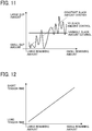
FIG. 11 is a graph illustrating changes over time in the remaining amount of the roll-type medium and the slippage amount of a print medium on a medium conveying roller; -
FIG. 12 is a graph illustrating the relation of the remaining amount of the roll-type medium and the time that is assumed to be appropriate to pull the roll-type medium with respect to the remaining amount of the roll-type medium; -
FIG. 13 is a flowchart illustrating the flow of a printing operation; -
FIG. 14 is a flowchart illustrating the flow of a slack control prior to the start of the printing operation; -
FIG. 15 is a flowchart illustrating the flow of the slack control; -
FIG. 16 is a flowchart for explaining an updating operation of the value of the outer diameter of a roll-type medium wound by a medium winding cardboard tube during the printing operation; -
FIGS. 17A and 17B are diagrams each explaining a change in the value of the outer diameter of the roll-type medium wound by the medium winding cardboard tube and a change in an encoder pulse; -
FIG. 18 is a graph illustrating the changes of a voltage value to be supplied from a motor controller to a medium winding motor, during the winding of the roll-type medium and after completion of the winding of the roll-type medium; and -
FIG. 19 is a graph illustrating the changes in the number of pulses of the encoder pulse detected by a medium wound amount encoder sensor, during the winding of the roll-type medium and after completion of the winding of the roll-type medium. - The accompanying drawings are intended to depict embodiments of the present disclosure and should not be interpreted to limit the scope thereof. The accompanying drawings are not to be considered as drawn to scale unless explicitly noted.
- It will be understood that if an element or layer is referred to as being "on," "against," "connected to" or "coupled to" another element or layer, then it can be directly on, against, connected or coupled to the other element or layer, or intervening elements or layers may be present. In contrast, if an element is referred to as being "directly on," "directly connected to" or "directly coupled to" another element or layer, then there are no intervening elements or layers present. Like numbers referred to like elements throughout. As used herein, the term "and/or" includes any and all combinations of one or more of the associated listed items.
- Spatially relative terms, such as "beneath," "below," "lower," "above," "upper" and the like may be used herein for ease of description to describe one element or feature's relationship to another element(s) or feature(s) as illustrated in the figures. It will be understood that the spatially relative terms are intended to encompass different orientations of the device in use or operation in addition to the orientation depicted in the figures. For example, if the device in the figures is turned over, elements describes as "below," or "beneath" other elements or features would then be oriented "above" the other elements or features. Thus, term such as "below" can encompass both an orientation of above and below. The device may be otherwise oriented (rotated 90 degrees or at other orientations) and the spatially relative descriptors herein interpreted accordingly.
- The terminology used herein is for describing particular embodiments and examples and is not intended to be limiting of exemplary embodiments of this disclosure. As used herein, the singular forms "a," "an," and "the" are intended to include the plural forms as well, unless the context clearly indicates otherwise. It will be further understood that the terms "includes" and/or "including," when used in this specification, specify the presence of stated features, integers, steps, operations, elements, and/or components, but do not preclude the presence or addition of one or more other features, integers, steps, operations, elements, components, and/or groups thereof.
- Referring now to the drawings, embodiments of the present disclosure are described below. In the drawings for explaining the following embodiments, the same reference codes are allocated to elements (members or components) having the same function or shape and redundant descriptions thereof are omitted below.
- A description is given of an image forming apparatus, a method for controlling medium supply, and a carrier medium carrying computer readable code that causes a computer to execute the method, according to an embodiment of the present disclosure with reference to drawings. In each drawing below, the same configuration shares the same reference numeral and the overlapped description may be omitted.
- Hereinafter, an image forming apparatus according to an embodiment is described with reference to the accompanying drawings. In the description of the present embodiment, "text printing" is not distinguished from "printing", and there is no intention of excluding printing other than texts from "printing", for example. In the present embodiment, general image formation using ink or toner on a medium is referred to as "printing."
-
FIG. 1 is an external perspective view illustrating an example of an external configuration of animage forming apparatus 100 according to an embodiment of the present disclosure. - The
image forming apparatus 100 is an inkjet type image forming apparatus. Theimage forming apparatus 100 includes aguide rod 3 and asub-guide rail 4 bridged between both side plates of ahousing 1 of theimage forming apparatus 100. Theimage forming apparatus 100 further includes acarriage 5 held by theguide rod 3 and thesub-guide rail 4. Thecarriage 5 is movable in a main-scanning direction indicated by arrow "A." - The
carriage 5 is coupled to atiming belt 11 wound around adrive pulley 9 and apressure pulley 10. Theimage forming apparatus 100 includes amain scanning motor 8 to move thetiming belt 11 via thedrive pulley 9 to reciprocally move thecarriage 5 in the-main scanning direction A. Thepressure pulley 10 applies tension to thetiming belt 11, so that thecarriage 5 is driven without generating slack. -
FIG. 2 is a plan view illustrating a carriage scanning mechanism of theimage forming apparatus 100 ofFIG. 1 . - In the carriage scanning mechanism illustrated in
FIG. 2 , the print medium M is intermittently conveyed in a sub-scanning direction indicated by arrow B below a scanning area along the lower part of thecarriage 5 in which thecarriage 5 reciprocally moves in a main scanning direction indicated by arrow A. The recording heads 6k, 6c, 6m, and 6y discharge ink from a plurality of nozzles to the print medium M, so that a predetermined image or a predetermined text is printed on the print medium M. Note that the suffixes of the recording heads 6k, 6c, 6m, and 6y indicate respective ink colors. To be more specific, "k" represents black or a key plate, "c" represents cyan, "m" represents magenta, and "y" represents yellow. Hereinafter, the recording heads 6k, 6c, 6m, and 6y are also referred to as the "recording heads 6" or the "recording head 6" in a singular form. - As illustrated in
FIG. 1 , theimage forming apparatus 100 includes a cartridge 7 and amaintenance mechanism 15 in thehousing 1. The cartridge 7 supplies the ink to the recording heads 6. Themaintenance mechanism 15 performs maintenance on the recording heads 6 mounted on thecarriage 5. Further, thecarriage 5 includes anencoder sensor 13, as illustrated inFIG. 2 . Theencoder sensor 13 continuously reads anencoder sheet 14 spanned on both side plates to detect the position of thecarriage 5 in the main scanning direction. Thecarriage 5 is controlled to move between the two side plates based on the position in the main scanning direction detected by theencoder sensor 13. Further, thecarriage 5 is provided with animage capturing unit 101 that moves together with thecarriage 5. Theimage capturing unit 101 reads the color patch of the reference chart and performs the colorimetric operation for each type of sheet. -
FIG. 3 is a diagram for explaining a medium conveyance mechanism for conveying a roll-type medium M0. - The roll-type medium M0 corresponds to the print medium M wound in a roll shape in the
image forming apparatus 100 ofFIG. 1 . InFIG. 3 , thecarriage 5 is provided with the recording heads 6 (that is, the recording heads 6k, 6c, 6m, and 6y) and performs the printing operation on aplaten 25 of theimage forming apparatus 100. Note that the recording heads 6 and theplaten 25 form an example of a printer. The roll-type medium M0 is set in a medium feed unit in the state in which the roll-type medium M0 is wound around a medium feedingcardboard tube 52 that is an example of a medium supplier. The roll-type medium M0 rotates as the print medium M is pulled in the direction indicated by arrow inFIG. 3 , which is referred to as a medium conveyance direction. The print medium M passes through the print area on theplaten 25 via themedium conveying roller 35 that is an example of a medium conveyor. The print medium M is then wound around a medium windingcardboard tube 44 set on a medium winding unit. The medium windingcardboard tube 44 is an example of a medium winder. - The medium winding unit includes a medium winding
encoder sheet 45, a medium woundamount encoder sensor 39, and atorque limiter 40. The medium windingencoder sheet 45 detects the number of rotations of the medium windingcardboard tube 44. Thetorque limiter 40 is connected to the medium windingcardboard tube 44 to rotate together with the medium windingcardboard tube 44 and limits the torque applied to the print medium M, in other words, manages the maximum torque value. The medium winding unit further includes amedium winding motor 41, a medium windingmotor encoder sheet 42, and a medium windingmotor encoder sensor 43. Themedium winding motor 41 functions as a drive source when performing a medium winding and slacking operation. The medium windingmotor encoder sheet 42 and the medium windingmotor encoder sensor 43 are mounted on the shaft of themedium winding motor 41 and detects the rotational speed of themedium winding motor 41 and the number of rotations of themedium winding motor 41. - The medium feeding unit includes a medium remaining
amount encoder sheet 51, a medium remainingamount encoder sensor 46, and atorque limiter 47. The medium remainingamount encoder sheet 51 and the medium remainingamount encoder sensor 46 detect the number of rotations of the mediumfeeding cardboard tube 52. Thetorque limiter 47 limits the torque applied to the roll-type medium M0, in other words, manages the maximum torque value. Further, the medium feeding unit includes amedium feeding motor 49, a medium feedingmotor encoder sheet 48, and a medium feedingmotor encoder sensor 50. Themedium feeding motor 49 functions as a drive source to generate tension of the medium feeding unit. The medium feedingmotor encoder sheet 48 and the medium feedingmotor encoder sensor 50 are mounted on the shaft of themedium feeding motor 49 and detects the rotational speed of themedium feeding motor 49 and the number of rotations of themedium feeding motor 49. - While performing a printing operation, the
medium feeding motor 49 is rotated to apply a force in the reverse direction opposite the medium conveyance direction indicated by arrow inFIG. 3 , to the roll-type medium M0. By so doing, the tension force is applied to the print medium M while the print medium M is held by themedium conveying roller 35 and apressure roller 34, and thetorque limiter 47 starts to slip. Accordingly, a constant torque amount is applied to the roll-type medium M0, and therefore the medium feed tension force according to the outer diameter of the roll-type medium M0 is applied to the print medium M. - The medium conveyance unit includes a
medium conveying motor 37, a medium conveyingmotor encoder sheet 38, and a medium conveyingmotor encoder sensor 36. Themedium conveying motor 37 functions as a drive source to rotate themedium conveying roller 35. The medium conveyingmotor encoder sheet 38 and the medium conveyingmotor encoder sensor 36 are mounted on the shaft of themedium conveying roller 35 and detects the rotational speed of themedium conveying motor 37 and the number of rotations of themedium conveying motor 37. -
FIG. 4 is a diagram for explaining the mediumfeeding cardboard tube 52 and a peripheral mechanism of the mediumfeeding cardboard tube 52. - As illustrated in
FIG. 4 , the medium feedingcardboard tube 52 is sandwiched and held by medium feedingcardboard tube flanges 78 from the left side and the right side of the mediumfeeding cardboard tube 52. Then, themedium feeding motor 49 rotates the medium feedingcardboard tube flange 78 via thetorque limiter 47 to rotate the mediumfeeding cardboard tube 52. Further, the medium remainingamount encoder sheet 51 is mounted on the shaft of the medium feedingcardboard tube flange 78. The medium remainingamount encoder sensor 46 outputs an encoder pulse according to the rotational speed of the medium remainingamount encoder sheet 51. The number of rotations, rotational position, and rotational speed of the mediumfeeding cardboard tube 52 are calculated based on the number of pulses of this encoder pulse. - Similar to the medium
feeding cardboard tube 52, the medium windingcardboard tube 44 is sandwiched and held by medium windingcardboard tube flanges 82, which has the same configuration as the medium feedingcardboard tube flange 78, from the left side and the right side of the medium windingcardboard tube 44, as illustrated inFIG. 4 . Then, themedium winding motor 41 rotates the medium windingcardboard tube flange 82 via thetorque limiter 40 to rotate the medium windingcardboard tube 44. The medium windingencoder sheet 45 is mounted on the shaft of the medium windingcardboard tube flange 82. The medium woundamount encoder sensor 39 outputs an encoder pulse according to the rotational speed of the medium windingencoder sheet 45. The number of rotations, position of rotation, and rotational speed of the medium windingcardboard tube 44 are calculated based on the number of pulses of this encoder pulse. -
FIG. 5 is a block diagram illustrating a main-sub drive controller 105 provided in theimage forming apparatus 100 ofFIG. 1 . - As illustrated in
FIG. 5 , theimage forming apparatus 100 is provided with the main-sub drive controller 105 that includes a controller 61, amain scanner 62, a medium conveyor 63, amedium feeder 64, amedium winder 65, and a memory 84. The controller 61 is an example of a rotation controller. Themedium feeder 64 is an example of a medium supplier. The memory 84 stores a medium supply control program. - The
main scanner 62 includes themain scanning motor 8, thecarriage 5, the recording heads 6 (i.e., the recording heads 6k, 6c, 6m, and 6y), and a main scanning encoder sensor 71. Themain scanning motor 8 drives thecarriage 5. The recording heads 6 and the main scanning encoder sensor 71 are mounted on thecarriage 5. - The medium conveyor 63 includes the
medium conveying roller 35 and the mediumconveyance encoder sensor 73. Themedium conveying roller 35 is driven by themedium conveying motor 37. The mediumconveyance encoder sensor 73 outputs the encoder pulse that changes as themedium conveying roller 35 rotates. - The
medium feeder 64 includes the medium feedingcardboard tube flanges 78, the medium feedingmotor encoder sensor 50, and the medium remainingamount encoder sensor 46. The medium feedingcardboard tube flanges 78 are driven by themedium feeding motor 49. The medium feedingmotor encoder sensor 50 outputs the encoder pulse that changes themedium feeding motor 49 rotates. The medium remainingamount encoder sensor 46 outputs the encoder pulse that changes as the medium feedingcardboard tube 52 rotates. - That is, the
medium feeder 64 includes two encoders, which are the medium feedingmotor encoder sensor 50 that detects rotation of the shaft of themedium feeding motor 49 and the medium remainingamount encoder sensor 46 that detects rotation of the medium feeding cardboard tube 52 (medium feeding cardboard tube flanges 78). Therefore, two encoder values are obtained from themedium feeder 64. Therefore, when performing the slack amount control, the encoder value of the medium remainingamount encoder sensor 46 is fed back as an input value to perform the rotation control of themedium feeding motor 49. By so doing, the slack amount is controlled with higher accuracy. - Alternatively, the feedback control of the
medium feeding motor 49 may be performed using the encoder value of the medium feedingmotor encoder sensor 50, and the target value of the medium feedingmotor encoder sensor 50 may be changed regularly, for example, once every 100 msec. or once every 200 msec., according to the difference of the target value of the medium feedingmotor encoder sensor 50 and the target value of the medium remainingamount encoder sensor 46. - The
medium winder 65 includes the medium windingcardboard tube flanges 82 and the medium windingmotor encoder sensor 43. The medium windingcardboard tube flanges 82 are driven by themedium winding motor 41. The medium windingmotor encoder sensor 43 outputs the encoder pulse that changes as themedium winding motor 41 rotates. Further, themedium winder 65 includes the medium woundamount encoder sensor 39 that outputs the encoder pulse that changes as the medium windingcardboard tube 44 rotates. - Note that, in the following description, the rotation control of each of the motors is performed based on the encoder value according to the rotation of the motor shaft. The encoder value is fed back from the motor encoder sensor.
-
FIG. 6 is a functional block diagram of the controller 61. - The controller 61 executes the medium supply control program that is stored in the memory 84 illustrated in
FIG. 5 . The medium supply control program is an example of a medium winding control program. By so doing, as illustrated inFIG. 6 , the controller 61 executes the functions of aprint controller 85, amotor controller 86, asensor processor 87, a roll remaining amount detector 88, and a slackindication value calculator 89. The roll remaining amount detector 88 is an example of a remaining amount detector. - Note that, in this example, the functions of the
print controller 85, themotor controller 86, thesensor processor 87, the roll remaining amount detector 88, and the slackindication value calculator 89 are implemented in software. However, a part of the functions or the whole functions may be implemented by hardware such as an integrated circuit (IC). Further, the functions implemented by theprint controller 85, themotor controller 86, thesensor processor 87, the roll remaining amount detector 88, and the slackindication value calculator 89 may be implemented by the medium supply control program alone, a part of the processes may be executed by another program, or the processes may be indirectly executed by another program. - Alternatively, the medium supply control program may be stored in a computer-readable storage medium such as a compact disc read-only memory (CD-ROM) or a flexible disk (FD), in a file in installable or executable format, thus being providable. Alternatively, the medium supply control program may be stored in a computer-readable storage medium such as a compact disc recordable (CD-R), a digital versatile or video disk (DVD) or a Bluray disc (BD) (registered), in a file in installable or executable format, thus being providable. Alternatively, the medium supply control program may be provided to be installed via a network such as the Internet or provided in a form previously embedded in, for example, a read only memory (ROM) in the device.
- The
print controller 85 issues drive instructions to themain scanning motor 8, themedium conveying motor 37, themedium feeding motor 49, and themedium winding motor 41. For example, a direct current (DC) motor may be used as themain scanning motor 8, themedium conveying motor 37, themedium feeding motor 49, and themedium winding motor 41. Themotor controller 86 refers to the encoder value that is detected by thesensor processor 87. Then, themotor controller 86 performs the speed control and positioning control (position control) of themain scanning motor 8, themedium conveying motor 37, themedium feeding motor 49, and themedium winding motor 41, with the feedback control that is described below. - Further, when rotating the medium
feeding cardboard tube 52, the slack amount of the roll-type medium M0 varies depending on the outer diameter of the roll-type medium M0. Therefore, the number of rotations of the mediumfeeding cardboard tube 52 is changed according to the outer diameter of the roll-type medium M0. Accordingly, the constant slack amount is provided without being affected by the outer diameter of the roll-type medium M0. The roll remaining amount detector 88 detects the remaining amount of the roll-type medium M0. More specifically, the roll remaining amount detector 88, which is also referred to as a diameter detector, detects the outer diameter of the roll-type medium M0 that is remaining on the mediumfeeding cardboard tube 52, based on the count value of the encoder pulse from the medium remainingamount encoder sensor 46 detected by thesensor processor 87. A detailed description of this operation will be described below. - The slack
indication value calculator 89 calculates the slack indication value that corresponds to the number of rotation pulses of themedium feeding motor 49 with respect to the medium slacking direction, so as to obtain a desired slack amount, based on the value of the outer diameter of the roll-type medium M0 calculated by the roll remaining amount detector 88. -
FIG. 7 is a diagram illustrating a configuration for a feedback control of themain scanning motor 8, themedium conveying motor 37, themedium feeding motor 49, and themedium winding motor 41. - As an example, in
FIG. 7 , themotor controller 86 and thesensor processor 87 are implemented in software based on the medium supply control program as described above. Further, themotor driver 90, themain scanning motor 8, themedium conveying motor 37, themedium feeding motor 49, themedium winding motor 41, the medium woundamount encoder sensor 39, the medium windingmotor encoder sensor 43, the medium remainingamount encoder sensor 46, the medium feedingmotor encoder sensor 50, the main scanning encoder sensor 71, and the mediumconveyance encoder sensor 73 are implemented in hardware. - In
FIG. 7 , themotor controller 86 causes a target generator 91 to generate the target position and target speed of each of themain scanning motor 8, themedium conveying motor 37, themedium feeding motor 49, and themedium winding motor 41. A proportional integral differential (PID) controller 93 generates a voltage command value corresponding to the target position and target speed and supplies the voltage command value to themotor driver 90. Note that, as an example, the voltage command value is supplied to themotor driver 90 in the form of a pulse width modulation signal (PWM signal). - The
motor driver 90 applies a drive voltage corresponding to the voltage command value to each of themain scanning motor 8, themedium conveying motor 37, themedium feeding motor 49, and themedium winding motor 41, to drive and rotate themain scanning motor 8, themedium conveying motor 37, themedium feeding motor 49, and themedium winding motor 41. The medium woundamount encoder sensor 39, the medium windingmotor encoder sensor 43, the medium remainingamount encoder sensor 46, the medium feedingmotor encoder sensor 50, the main scanning encoder sensor 71, and the mediumconveyance encoder sensor 73 form an encoder pulse that corresponds to the rotational speed of each of themain scanning motor 8, themedium conveying motor 37, themedium feeding motor 49, and themedium winding motor 41, and supplies the encoder pulse to thesensor processor 87. Thesensor processor 87 causes arotation detector 94 to detect the current rotational speed and rotational position of each of themain scanning motor 8, themedium conveying motor 37, themedium feeding motor 49, and themedium winding motor 41, based on the encoder pulse, and feeds back to themotor controller 86. Themotor controller 86 causes acomparison unit 92 to detect a difference of the target position and target speed generated by the target generator 91 and the current rotational speed and rotational position that are fed back by thesensor processor 87, and supplies the signal of the difference, in other words, the differential signal, to the PID controller 93. - The PID controller 93 generates a voltage command value that makes the difference indicated by the differential signal, of the target position and target speed generated by the target generator 91 and the current rotational speed and rotational position that are fed back by the
sensor processor 87 to zero (0). Then, the PID controller 93 supplies the voltage command value to themotor driver 90. Accordingly, themain scanning motor 8, themedium conveying motor 37, themedium feeding motor 49, and themedium winding motor 41 rotate at the target position and target speed generated by the target generator 91. -
FIGS. 8A and 8B are diagrams each explaining the slack amount of the roll-type medium M0. - The slack amount of the roll-type medium M0 is represented by the length of the print medium M. For example, the slack amount is 10 mm when the print medium M is fed by the length of 10 mm from the roll-type medium M0 that is wound around the medium feeding
cardboard tube 52 with no slack, in other words, when the roll-type medium M0 is rotated by the angle that corresponds to the length of the outer circumference of the roll-type medium M0 by 10 mm. Further, this slack amount equals to the length of the print medium M when themedium conveying roller 35 conveys the print medium M by 10 mm in the reverse direction from the roll-type medium M0 with no slack. -
FIGS. 9A, 9B, 9C, 9D, and 9E are diagrams each explaining a slack control operation. -
FIG. 10 is a time chart illustrating the timing of signals of each unit for explaining a slack control. - To be more specific, part (a) of
FIG. 10 indicates the timing of a scanning operation of the roll-type medium M0 in the main scanning direction to form an image. Part (b) ofFIG. 10 indicates the timing of a medium conveyance operation of the roll-type medium M0. Part (c) ofFIG. 10 indicates the timing of driving the medium winding operation of the roll-type medium M0. Part (d) ofFIG. 10 indicates the slack amount of the roll-type medium M0. Part (e) ofFIG. 10 indicates the medium tension of the print medium M on theplaten 25. Part (f) ofFIG. 10 indicates the conveyance state of the roll-type medium M0. -
FIG. 9A illustrates the state of the roll-type medium M0 while conveyance of the roll-type medium M0 is suspended immediately before the medium conveyingroller 35 conveys the print medium M. In other words,FIG. 9A indicates the state of the roll-type medium M0 immediately before conveyance. This state corresponds to the state (1) in part (f) ofFIG. 10 . In this state, the medium feedingcardboard tube 52 is under the positioning stop control by themedium feeding motor 49 while the desired slack position is maintained. Note that the positioning control is performed by the feedback control described above with reference toFIG. 7 . That is, when the medium feedingmotor encoder sensor 50 detects the positional deviation of the roll-type medium M0 from the desired position, the control to return the rotational position of themedium feeding motor 49 to the desired position is performed repeatedly. Accordingly, the medium feedingcardboard tube 52 continues to stop at the desired position. - Next,
FIG. 9B indicates the operation of the first half of conveyance of the print medium M and illustrates the state in which the slack amount of the roll-type medium M0 decreases as themedium conveying motor 37 starts to convey the print medium M. This state corresponds to the state (2) in part (f) ofFIG. 10 . Note that, at the start of this conveyance, themedium feeding motor 49 continues to perform the position control to maintain the target slack position. - Next,
FIG. 9C illustrates the state during the operation of the second half of conveyance of the print medium M. This state corresponds to the state (3) in part (f) ofFIG. 10 . By starting the medium winding operation after the predetermined standby time has elapsed, for example, in a range from 100 ms to 500 ms, from the start of the conveyance operation, the timing to start applying the tension in the second half of conveyance of the print medium M is adjusted. Note that the above-described standby time depends on the outer diameter of the roll-type medium M0. - When the
medium feeding motor 49 is driven to start winding the roll-type medium M0, the slack amount turns to zero (0). Then, until the conveyance of the print medium M is stopped, themedium conveying roller 35 and the mediumfeeding cardboard tube 52 pull the print medium M away from each other. At that time, themedium feeding motor 49 does not stop and thetorque limiter 47 slips, so that the print medium M receives the tension force according to the allowable upper torque (torque limiter value) of thetorque limiter 47 and the outer diameter of the roll-type medium M0. - Next,
FIG. 9D illustrates the state of the operation in which themedium feeding motor 49 is rotated in reverse, in other words, in the reverse direction opposite the medium winding direction (i.e., the normal direction) of the roll-type medium M0, to generate the slack of the roll-type medium M0 intentionally while the conveyance of the print medium M is suspended (during suspension of the conveyance of the print medium M). This state corresponds to the state (4) in part (f) ofFIG. 10 . This shifting to the slack generation operation is performed, that is, the rotation of themedium feeding motor 49 is switched from the normal direction to the reverse direction, after the predetermined time has elapsed from the completion of conveyance of the print medium M. - Note that the shifting of the operation may be controlled to previously monitor the constant output voltage command value of the medium feeding motor 49 (see
FIG. 7 ), set the voltage command value at the start of slippage of thetorque limiter 47 as a threshold, finish winding the roll-type medium M0 around the medium feedingcardboard tube 52 when the output voltage command value of themedium feeding motor 49 reaches the threshold, and switch the rotational direction of themedium feeding motor 49 at the predetermined timing. The detailed description of this control is given below. - Next,
FIG. 9E illustrates the state in which the target slack is held after the conveyance of the print medium M is suspended. This state corresponds to the state (5) in part (f) ofFIG. 10 . Providing a certain slack amount as described above reduces the shock due to themedium conveying roller 35 and the mediumfeeding cardboard tube 52 pulling the roll-type medium M0 away from each other when themedium conveying roller 35 starts to convey the print medium M. This pulling of the roll-type medium M0 by themedium conveying roller 35 and the mediumfeeding cardboard tube 52 at the start of conveyance of the print medium M applies the tension to the print medium M. This application of the tension achieves a reduction in skew of the print medium M due to the difference of tensions applied on the left and right sides of the roll-type medium M0 and a reduction in variation in the slippage amount of the print medium M on themedium conveying roller 35 by the application of the tension. Accordingly, the printing quality is enhanced. -
FIG. 11 is a graph illustrating changes over time in the remaining amount of the roll-type medium M0 and the slippage amount of the print medium M on themedium conveying roller 35. - As illustrated in the graph of
FIG. 11 , when the slack control is not performed, the tension force of the print medium M is applied randomly to the print area on theplaten 25. In order to prevent this inconvenience, in the present embodiment, a constant slack amount control and a variable slack amount control are performed. The constant slack amount control provides a constant slack amount to make the change in the remaining amount of the roll-type medium M0 proportional to the slippage amount of the print medium M. The variable slack amount control changes the slack amount of the roll-type medium M0 according to the change of the remaining amount of the roll-type medium M0 to maintain the constant slippage amount of the print medium M. - In the constant slack amount control, when generating the slack of the roll-type medium M0, in order to make the constant slack amount, the positioning control is continuously performed at the position, according to the number of rotations of the motor (i.e., the number of rotations of the medium feeding cardboard tube 52) calculated based on the outer diameter of the roll-type medium M0 wound around the medium feeding
cardboard tube 52. Accordingly, the constant tension of the print medium M is applied to the print area on theplaten 25, and the image quality (print quality) is enhanced. - Further, the variable slack amount control gradually increases the slack amount of the roll-type medium M0 to shorten the time to pull the print medium M as the remaining amount of the roll-type medium M0 is reduced, in other words, as the outer diameter of the roll-type medium M0 decreases and the tension applied to the print medium M increases. By contrast, the variable slack amount control delays the medium winding speed of the
medium feeding motor 49 to delay the time to start application of the tension to the print medium M. Accordingly, the constant slippage amount is given to the print medium M on theplaten 25 from the start to the end of conveyance of the print medium M, regardless of the remaining amount of the roll-type medium M0, i.e., the outer diameter of the roll-type medium M0. -
FIG. 12 is a graph illustrating the remaining amount of the roll-type medium M0, relative to the time that is assumed to be appropriate to pull the roll-type medium M0 with respect to the remaining amount of the roll-type medium M0. - The slope of this graph is determined and set by evaluation. Further, a table or an approximate expression may be used instead of a graph. Note that, if the variation between the successive medium conveyance operations is small and the desired image quality is satisfied, the constant slack amount control may be performed.
- When the distance of conveyance of the print medium M changes, the slack amount is separately set according to the distance of intermittent conveyance by the
medium conveying roller 35. By so doing, even if the distance of conveyance of the print medium M changes, the timing to start application of the tension to the print medium M is adjusted to provide the same period of time to apply the tension. This state corresponds to the state (2) of part (f) ofFIG. 10 . Further, when the type of the medium is changed, the slippage amount of the print medium M on themedium conveying roller 35 changes. Therefore, by setting the slack amount according to the type of the medium, a control such as the matching control to match the slippage amount of the print medium M with the slippage amount of another medium is performed. - The conveyance of the roll-type medium M0 is started as illustrated in parts (b) to (f) of
FIG. 10 , and the roll-type medium M0 is wound without slack as illustrated in parts (d) and (e) ofFIG. 10 before forming an image (printing texts) as illustrated in part (a) ofFIG. 10 . Then, the predetermined slack amount is applied to the roll-type medium M0 again, and the image is formed (the texts are printed) on theplaten 25 with respect to the roll-type medium M0 while the predetermined slack amount is generated. Accordingly, the flatness of the print medium M on theplaten 25 is increased for printing, and therefore the good printing operation is performed. - Note that the timing of application of the tension to the roll-type medium M0 is not limited to the timing before image formation. As long as tension that does not affect the print medium M on the
platen 25 is applied to the roll-type medium M0, the timing of application of the tension to the roll-type medium M0 may be, for example, the timing of image formation (that is, during image formation) as illustrated in part (a) ofFIG. 10 . Accordingly, the productivity of the printed product is enhanced. - Further, the timing of generating the predetermined slack to the roll-type medium M0 may be, for example, the timing of image formation (that is, during image formation) as illustrated in part (a) of
FIG. 10 . Accordingly, the productivity of the printed product is enhanced. -
FIG. 13 is a flowchart illustrating the flow of the printing operation performed in theimage forming apparatus 100. - In the flowchart of
FIG. 13 , as an initial operation, themotor controller 86, thesensor processor 87, the roll remaining amount detector 88, and the slackindication value calculator 89, which are included in the controller 61 as illustrated inFIG. 6 , perform the slack control prior to the start of the printing operation. By performing the slack control prior to the start of the printing operation, the controller 61 generates the predetermined slack on the roll-type medium M0 (step S1), and then starts conveyance of the roll-type medium M0 (step S2). - As the conveyance of the roll-type medium M0 is started, the
motor controller 86, thesensor processor 87, the roll remaining amount detector 88, and the slackindication value calculator 89 stand by until the predetermined standby time, for example, 200 msec. has elapsed (step S3). When the predetermined standby time has not elapsed (NO in step S3), the process in step S3 is repeated. When the predetermined standby time has elapsed (YES in step S3), the controller 61 starts to wind the roll-type medium M0 (step S4). When the winding of the roll-type medium M0 is completed, the controller 61 stops conveyance of the roll-type medium M0 (step S5). - That is, the controller 61 starts to rotate the medium
feeding cardboard tube 52 in the medium winding direction at the predetermined timing after themedium conveying roller 35 has started intermittent conveyance of the roll-type medium M0 and before the medium conveyingroller 35 completes the intermittent conveyance of the roll-type medium M0. - Next, the
print controller 85 of the controller 61 starts image formation in the main scanning direction (step S6). Then, it is determined whether the predetermined time, for example, 200 msec. has elapsed (step S7). When the predetermined time has not elapsed (NO in step S7), the process in step S7 is repeated. When the predetermined time has elapsed (YES in step S7), themotor controller 86, thesensor processor 87, the roll remaining amount detector 88, and the slackindication value calculator 89 stop the winding of the roll-type medium M0 (step S8). Subsequently, themotor controller 86, thesensor processor 87, the roll remaining amount detector 88, and the slackindication value calculator 89 perform the reverse rotation control of themedium feeding motor 49 to perform the slack control to generate the slack on the roll-type medium M0 intentionally (step S9). - When the slack is generated on the roll-type medium M0, in order to have a constant slack amount, according to the number of rotations of the motor (that is, the number of rotations of the medium feeding cardboard tube 52) calculated based on the outer diameter of the roll-type medium M0 that is wound around the medium feeding
cardboard tube 52, the positioning control is continuously performed at the position. Accordingly, the constant tension of the print medium M is applied to the print area on theplaten 25. In this state, theprint controller 85 performs image formation in the main scanning direction. When the image formation is completed (step S10), theprint controller 85 determines whether the printing operation is finished (step S11). - When the printing operation is finished in step S11, that is, when the image formation is completed to the extreme downstream side in the sub-scanning direction (YES in step S11), the operation of the flowchart of
FIG. 13 is completed. When the printing operation is not finished in step S11 (that is, NO in step S11), the controller 61 repeats the flow from the process in step S2. -
FIG. 14 is a flowchart illustrating the flow of the slack control prior to the start of the printing operation (step S1). - The flowchart of
FIG. 14 illustrates the flow of the slack control operation based on the outer diameter of the roll-type medium M0 that has already wound before the printing operation. - First, as illustrated in
FIG. 3 , the roll-type medium M0 is attached to the mediumfeeding cardboard tube 52 and the medium windingcardboard tube 44 and is set to the state that is ready to start the printing operation and the medium winding operation. When starting the printing operation, the current state of the roll-type medium M0 may change, for example, when a user replaces the mediumfeeding cardboard tube 52. Therefore, after the value of the outer diameter of the roll-type medium M0 that is wound around the medium feedingcardboard tube 52 is calculated, the following slack control is performed, and then the printing operation is performed. - In the flowchart of
FIG. 14 , when the controller 61 starts to wind the roll-type medium M0 (step S21), themotor controller 86, thesensor processor 87, and the roll remaining amount detector 88 cause themedium feeding motor 49 to continue to wind the roll-type medium M0 around the medium feedingcardboard tube 52, for example, for 5 seconds (step S22). Accordingly, the roll-type medium M0 is tightly wound around the medium feedingcardboard tube 52. At this stage, the slack amount of the roll-type medium M0 is 0 mm. - In this state, the roll remaining amount detector 88 maintains the encoder value of the medium remaining amount encoder sensor 46 (step S23). As an example, the encoder value maintained in the roll remaining amount detector 88 is assumed to indicate the position at 100 pulses. After the encoder value is thus acquired, the
motor controller 86, thesensor processor 87, and the roll remaining amount detector 88 control themedium feeding motor 49 to stop (step S24). - Next, the
motor controller 86, thesensor processor 87, and the roll remaining amount detector 88 control themedium conveying roller 35 to convey the roll-type medium M0, for example, by 50 mm (step S25). Then, it is determined whether the roll-type medium M0 has been conveyed by 50 mm (step S26). When the roll-type medium M0 has not been conveyed by 50 mm (NO in step S26), the process in step S26 is repeated. When the roll-type medium M0 has completely been conveyed by 50 mm (YES in step S26), themotor controller 86, thesensor processor 87, and the roll remaining amount detector 88 cause themedium feeding motor 49 to wind the roll-type medium M0 around the medium feedingcardboard tube 52 again for 5 seconds (step S27). Then, it is determined whether the roll-type medium M0 is continuously wound for 5 seconds (step S28). When the roll-type medium M0 is not continuously wound for 5 seconds (NO in step S28), the process in step S28 is repeated. When the roll-type medium M0 is continuously wound for 5 seconds (YES in step S28), the slack amount becomes 0 mm. When the slack amount is set to 0 mm, the roll remaining amount detector 88 maintains the encoder value of the medium remaining amount encoder sensor 46 (step S29). - Note that the encoder value maintained by the roll remaining amount detector 88 is assumed to indicate the position at 200 pulses. After the encoder value is thus acquired, the
motor controller 86, thesensor processor 87, and the roll remaining amount detector 88 control to stop the medium feeding motor 49 (step S30). - Next, the slack
indication value calculator 89 calculates the outer diameter of the roll-type medium M0 wound around the medium feeding cardboard tube 52 (step S31). - As an example, the slack
indication value calculator 89 calculates the outer diameter of the roll-type medium M0 by using the following arithmetic expression (1).
- In the arithmetic expression (1), the circumference of the roll-type medium M0 is expressed as "the distance of conveyance x (the number of pulses according to rotation of the medium
feeding cardboard tube 52 detected by the medium woundamount encoder sensor 39 ÷ the differential pulse)". Therefore, when the number of pulses for one rotation of the mediumfeeding cardboard tube 52 detected by the medium remainingamount encoder sensor 46 is 1000 pulses, the circumference of the roll-type medium M0 is calculated as "50 mm × (1000 ÷ 100) = 500 mm." The outer diameter of the roll-type medium M0 is calculated as "500 ÷ π [mm]." Based on the outer diameter of the roll-type medium M0 calculated as described above, the slack control described below is performed (step S32). -
FIG. 15 is a flowchart illustrating the flow of the slack control (steps S9 and S32). - The slack control operation illustrated in the flowchart of
FIG. 15 calculates a slack indication value based on the thus calculated value of the outer diameter of the roll-type medium M0 that has been wound around the medium feedingcardboard tube 52. Then, the slack control operation performs the drive control of themedium feeding motor 49 with this slack indication value as a target value. By this slack control operation, an appropriate "slack" is intentionally generated. - That is, when the outer diameter of the roll-type medium M0 is calculated as described above, the slack
indication value calculator 89 acquires the calculated value of the outer diameter of the roll-type medium M0 (step S41). Then, the slackindication value calculator 89 calculates the slack indication value to control rotation of themedium feeding motor 49, based on the following arithmetic expression (2) (step S42).
- In the arithmetic expression (2) of the slack indication value, the number of rotations [pls] of the medium
feeding cardboard tube 52 is calculated by the following arithmetic expression (3).
- Further, the circumference of the wound roll-type medium M0 in the arithmetic expression (3) to obtain the number of rotations of the medium
feeding cardboard tube 52 is calculated by the following arithmetic expression (4).
- The
motor controller 86 starts the rotation control of themedium feeding motor 49 based on the thus calculated slack indication value to generate the slack (step S43). After themedium feeding motor 49 has reached the target position (indication stop position), themotor controller 86 continues the positioning control at the target position (step S44). - Such a slack control is repeated each time the roll-type medium M0 is conveyed intermittently.
- Note that, in the above description, the
medium feeding motor 49 is controlled based on the slack indication value calculated with the arithmetic expression (2) that is used to obtain the slack indication value. However, the control of themedium feeding motor 49 is not limited to the control based on the slack indication value. For example, the number of rotations of the mediumfeeding cardboard tube 52, which is calculated with the arithmetic expression (3) used to obtain the number of rotations of the mediumfeeding cardboard tube 52, may be calculated as a target position, and themedium feeding motor 49 may be controlled based on the target position. -
FIG. 16 is a flowchart for explaining an updating operation of the value of the outer diameter of the roll-type medium M0 during the printing operation. - Since the remaining amount of the roll-type medium M0 decreases during the printing operation, the slack indication value to the
medium feeding motor 49 is changed to maintain the constant slack amount even though the outer diameter of the roll-type medium M0 decreases. Therefore, concurrently with the above-described slack control operation, the outer diameter of the roll-type medium M0 is detected during the printing operation (in other words, each time the roll-type medium M0 is conveyed by, for example, 50 mm). By so doing, the value of the outer diameter of the roll-type medium M0 is updated. - That is, the roll remaining amount detector 88 firstly maintains the current encoder value of the medium remaining amount encoder sensor 46 (step S51). Next, the
motor controller 86 causes themain scanning motor 8, themedium conveying motor 37, themedium feeding motor 49, and themedium winding motor 41 to drive and rotate to convey the roll-type medium M0 (step S52). Further, theprint controller 85 discharges a discharge signal to the recording heads 6 and causes the recording heads 6 to discharge ink to perform the print control on the roll-type medium M0 in the main scanning direction (step S53). - Next, the roll remaining amount detector 88 determines whether the roll-type medium M0 has been conveyed by 50 mm or more from the update of the previous encoder value of the medium remaining amount encoder sensor 46 (step S54). Note that, as an example, the distance of conveyance of the roll-type medium M0 is preferably 50 mm to 100 mm.
- When it is determined in step S54 that the roll-type medium M0 has been conveyed by 50 mm or more (YES in step S54), the roll remaining amount detector 88 calculates the value of the current outer diameter of the roll-type medium M0 and updates the current encoder value of the medium winding motor encoder sensor 43 (step S55).
- Then, the controller 61 determines whether the printing operation has been finished (step S56). When it is determined in step S56 that the printing operation has been finished (YES in step S56), the controller 61 completes the processes of the flow in the flowchart of
FIG. 16 . By contrast, when it is determined in step S56 that the printing operation has not been finished (NO in step S56), the controller 61 returns to step S51 to repeat the process. Then, when it is determined that the roll-type medium M0 has been conveyed by 50 mm again (YES in step S54), the encoder value of the medium remainingamount encoder sensor 46 is detected and updated (step S55). - Further, when it is determined in step S54 that the roll-type medium M0 has not yet been conveyed by 50 mm, in other words, the distance of conveyance of the roll-type medium M0 is less than 50 mm (NO in step S54), the
print controller 85 determines whether the printing operation has been finished (step S56). - As described above, during the printing operation, the value of the outer diameter of the roll-type medium M0 is repeatedly detected each time the roll-type medium M0 is conveyed by a certain distance, in other words, each time the intermittent conveyance of the roll-type medium M0 is performed. The printing operation and the medium conveyance operation are repeated for multiple times. Then, after the roll-type medium M0 has been conveyed by 50 mm or more in total (for example, from 50 mm to 100 mm) from the previous update of the encoder value of the medium remaining
amount encoder sensor 46, the value of the outer diameter of the wound roll-type medium M0 is calculated and updated before the subsequent medium conveyance operation is performed. -
FIGS. 17A and 17B are diagrams each explaining a change in the value of the outer diameter of the roll-type medium M0 wound by the medium feedingcardboard tube 52 and a change in the encoder pulse. -
FIG. 17A illustrates the state in which the amount of the print medium M that is wound around the medium feedingcardboard tube 52 is small, that is, the outer diameter of the roll-type medium M0 is small. In this state, the amount of change (i.e., the angle of rotation) of the encoder pulse detected by the medium remainingamount encoder sensor 46 is large, and the number of change pulses is large. On the other hand,FIG. 17B illustrates the state in which the amount of the print medium M that is wound around the medium feedingcardboard tube 52 is large, that is, the outer diameter of the roll-type medium M0 is large. In this state, the amount of change (i.e., the angle of rotation) of the encoder pulse detected by the medium remainingamount encoder sensor 46 is small, and the number of change pulses is small. - That is, the angle of rotation of the medium
feeding cardboard tube 52 changes according to the outer diameter of the roll-type medium M0 wound around the medium feedingcardboard tube 52, and therefore the number of pulses of the encoder pulse changes. Therefore, the slackindication value calculator 89 calculates the slack indication value that is changed according to the outer diameter of the roll-type medium M0 that is wound around the medium feedingcardboard tube 52. Accordingly, even when the outer diameter of the roll-type medium M0 that is wound around the medium feedingcardboard tube 52 changes, the slack amount of the roll-type medium M0 maintains the constant slack amount. Further, the outer diameter of the roll-type medium M0 is calculated based on the change in the number of pulses of the encoder pulse detected by the medium remainingamount encoder sensor 46. - Next, a description is given of the detecting operation of completion of the winding of the roll-type medium M0 around the medium feeding
cardboard tube 52. As an example, theimage forming apparatus 100 according to the present embodiment detects completion of the winding the roll-type medium M0 based on the voltage command value that is supplied to themedium feeding motor 49 under the speed control. - To be more specific, when the roll-type medium M0 is completely wound around the medium feeding
cardboard tube 52, the medium winding operation is terminated and thetorque limiter 40 starts to slip. Themotor controller 86 increases the voltage value (changes the voltage indication value) to be supplied to themedium feeding motor 49 to maintain the rotational speed even when the load increases due to slippage of thetorque limiter 40. The increased voltage value and the threshold used to detect the increased voltage value are set and stored in advance. Then, the roll remaining amount detector 88 detects completion of the winding of the roll-type medium M0 when a voltage value exceeding the threshold is continuously detected for the predetermined time. -
FIG. 18 is a graph illustrating the changes of the voltage value that is supplied from themotor controller 86 to themedium feeding motor 49, during the medium winding operation of the roll-type medium M0 and after completion of the medium winding operation of the roll-type medium M0. - As an example, in this example of the graph of
FIG. 18 , the voltage value of 12.5V is set as a threshold. As illustrated in the graph ofFIG. 18 , themedium feeding motor 49 is driven at the contact voltage value equal to the threshold or below, during the medium winding operation of the roll-type medium M0. However, when the medium winding operation of the roll-type medium M0 is completed, the voltage value supplied from themotor controller 86 to themedium feeding motor 49 increases to exceed the threshold to maintain the number of rotations of themedium feeding motor 49 whose load has increased. - When the time in which the voltage value continuously exceeds the threshold for a certain period of time, for example, for 50 msec., the roll remaining amount detector 88 determines that the medium winding operation of the roll type medium M0 is completed.
- The example illustrated in
FIG. 18 is an example of detecting the completion of the medium winding operation of the roll-type medium M0 based on the voltage value that is supplied to themedium feeding motor 49. However, as described below, the completion of the medium winding operation of the roll-type medium M0 may be detected based on the number of pulses of the encoder pulse detected by the medium remainingamount encoder sensor 46. -
FIG. 19 is a graph illustrating the changes in the number of pulses of the encoder pulse detected by the medium remainingamount encoder sensor 46, during the medium winding operation of the roll-type medium M0 and after completion of the medium winding operation of the roll-type medium M0. - As illustrated in
FIG. 19 , the number of pulses of the encoder pulse detected by the medium remainingamount encoder sensor 46 gradually increases during the medium winding operation of the roll-type medium M0. However, when the medium winding operation is completed, the rotation of the mediumfeeding cardboard tube 52 stops, so that the number of pulses of the encoder pulse detected by the medium remainingamount encoder sensor 46 remains stopped at a constant number of pulses of the encoder pulse. - Therefore, when the constant number of pulses of the encoder pulse or the substantially constant number of pulses of the encoder pulse (in a transition range within ±3 pulses, for example) is continuously detected for a certain period of time, for example, 50 msec., the roll remaining amount detector 88 determines that the medium winding operation of the roll-type medium M0 is completed. That is, the controller 61 determines that the roll-type medium M0 that corresponds to the print medium M in a roll shape has been wound with no slack when an amount of change of the remaining amount of the print medium M is equal to or smaller than a predetermined value for a predetermined period of time.
- As described above, with a simpler configuration when compared with known image forming apparatuses, the
image forming apparatus 100 according to the present embodiment generates an appropriate amount of slack on the roll-type medium M0 at an appropriate timing and winds the slack of the roll-type medium M0 at an appropriate timing. By so doing, theimage forming apparatus 100 according to the present embodiment applies an appropriate tension to the print medium M at an appropriate timing. Accordingly, the skew is reduced to restrain the paper jam of the print medium M, and the variation in conveyance error is reduced to restrain the positional shift of an image. Consequently, the print quality is enhanced. - Finally, the above-described embodiments are presented as examples and are not intended to limit the scope of the present disclosure. The above-described embodiments can be implemented in other various forms, and various omissions, replacements, and changes can be made without departing from the scope of the invention. In addition, the embodiments and modifications or variations thereof are included in the scope and the gist of the invention and are included in the invention described in the claims and the equivalent scopes thereof.
- For example, other than ink used in the present embodiment, liquid to be discharged from the nozzles of the head is not limited to a particular liquid as long as the liquid has a viscosity or surface tension to be discharged from the head. However, preferably, the viscosity of the liquid is not greater than 30 mPa·s under ordinary temperature and ordinary pressure or by heating or cooling. More specifically, the liquid may be, e.g., an emulsion, a suspension, or a solution containing e.g., a solvent such as water or an organic solvent, a colorant such as a dye or a pigment, a polymerizable compound, a functionalizing material such as a resin or a surfactant, a biocompatible material such as a deoxyribonucleic acid (DNA), an amino acid, a protein, or a calcium, or an edible material such as a natural pigment. Emulsions, suspensions, or solutions can be used as, e.g., inks for inkjet printing, surface treatment liquids, liquids for forming electronic circuit resist patterns and components of electronic devices and light-emitting devices, and three-dimensional modeling material liquids.
- Further, examples of an energy source for generating energy to discharge liquid include a piezoelectric actuator (a laminated piezoelectric element or a thin-film piezoelectric element), a thermal actuator that employs a thermoelectric conversion element, such as a heating resistor (element), and an electrostatic actuator including a diaphragm and opposed electrodes.
- Further, for example, the above-described term "material onto which liquid adheres" (in the present embodiment, the print medium M) may represent, for example, a material or a medium on which liquid is at least temporarily adhered, a material or a medium on which liquid is adhered and fixed, or a material or a medium into which liquid is adhered and into which the liquid permeates. Examples of the "material onto which liquid adheres" include recording media or medium such as a paper sheet, a recording paper, and a recording sheet of paper, film, and cloth, electronic components such as an electronic substrate and a piezoelectric element, and media or medium such as a powder layer, an organ model, and a testing cell. The "material onto which liquid adheres" includes any material on which liquid adheres unless particularly limited.
- Further, examples of the "material onto which liquid adheres" include any materials on which liquid adheres even temporarily, such as paper, thread, fiber, fabric, leather, metal, plastic, glass, wood, and ceramic.
- Although the present disclosure makes reference to specific embodiments, it is to be noted that the present disclosure is not limited to the details of the embodiments and examples described above. For example, elements and/or features of different embodiments and examples may be combined with each other and/or substituted for each other within the scope of the present disclosure. The number of constituent elements and their locations, shapes, and so forth are not limited to any of the structure for performing the methodology illustrated in the drawings. Further, the present disclosure is not limited to the embodiments and examples described above. Thus, various modifications and enhancements are possible in light of the above teachings, without departing from the scope of the present disclosure.
- The above-described embodiments are illustrative and do not limit this disclosure. Thus, numerous additional modifications and variations are possible in light of the above teachings. For example, elements at least one of features of different illustrative and exemplary embodiments herein may be combined with each other at least one of substituted for each other within the scope of this disclosure and appended claims. Further, features of components of the embodiments, such as the number, the position, and the shape are not limited the embodiments and thus may be preferably set.
- The present disclosure is not limited to specific embodiments described above, and numerous additional modifications and variations are possible in light of the teachings within the technical scope of the appended claims. It is therefore to be understood that, the disclosure of this patent specification may be practiced otherwise by those skilled in the art than as specifically described herein, and such, modifications, alternatives are within the technical scope of the appended claims. Such embodiments and variations thereof are included in the scope and gist of the embodiments of the present disclosure and are included in the embodiments described in claims and the equivalent scope thereof.
- The above-described embodiments are illustrative and do not limit the present disclosure. Thus, numerous additional modifications and variations are possible in light of the above teachings. For example, elements and/or features of different illustrative embodiments may be combined with each other and/or substituted for each other within the scope of this disclosure.
- Any one of the above-described operations may be performed in various other ways, for example, in an order different from the one described above.
- The present invention can be implemented in any convenient form, for example using dedicated hardware, or a mixture of dedicated hardware and software. The present invention may be implemented as computer software implemented by one or more networked processing apparatuses. The processing apparatuses include any suitably programmed apparatuses such as a general purpose computer, personal digital assistant, mobile telephone (such as a WAP or 3G-compliant phone) and so on. Since the present invention can be implemented as software, each and every aspect of the present invention thus encompasses computer software implementable on a programmable device. The computer software can be provided to the programmable device using any conventional carrier medium (carrier means). The carrier medium includes a transient carrier medium such as an electrical, optical, microwave, acoustic or radio frequency signal carrying the computer code. An example of such a transient medium is a TCP/IP signal carrying computer code over an IP network, such as the Internet. The carrier medium may also include a storage medium for storing processor readable code such as a floppy disk, hard disk, CD ROM, magnetic tape device or solid state memory device.
Claims (15)
- An image forming apparatus (100) comprising:a medium supplier (52, 64) configured to supply a print medium (M) wound in a roll shape;a medium conveyor (63) configured to intermittently convey the print medium supplied by the medium supplier by a predetermined supply amount;a medium winder (44, 65) configured to wind the print medium conveyed by the medium conveyor;a printer (6, 25) configured to print on the print medium conveyed by the medium conveyor; anda rotation controller (61) configured to:cause the medium supplier to rotate in a medium winding direction at a predetermined timing after the medium conveyor has started to intermittently convey the print medium; andcause the medium supplier to rotate in a reverse direction opposite the medium winding direction to loosen the print medium.
- The image forming apparatus (100) according to claim 1, further comprising a diameter detector (88) configured to detect an outer diameter of the print medium (M) wound in a roll shape on the medium supplier (52),
wherein the rotation controller (61) is configured to cause the medium supplier (52, 64) to change an amount of rotation of the print medium (M) in the medium supplier (52, 64) according to a value of the outer diameter of the print medium (M) detected by the diameter detector (88), to maintain a slack amount of the print medium (M) constant. - The image forming apparatus (100) according to claim 1, further comprising a diameter detector (88) configured to detect an outer diameter of the print medium (M) wound in a roll shape on the medium supplier (52),
wherein the rotation controller (61) is configured to cause the medium supplier (52, 64) to change an amount of rotation of the print medium (M) to increase a slack amount of the print medium (M) as the outer diameter of the print medium (M) detected by the diameter detector (88) decreases. - The image forming apparatus (100) according to any one of claims 1 to 3, wherein the rotation controller is configured to:cause the medium supplier to rotate the print medium to no slack state of the print medium after the predetermined timing and before the medium conveyor starts to decelerate toward a stop of conveyance of the print medium; andmaintain the no slack state after the printer starts to print on the print medium.
- The image forming apparatus (100) according to any one of claims 1 to 4,
wherein the rotation controller is configured to change the slack amount of the print medium according to a distance at which the medium conveyor conveys the print medium in a subsequent intermittent conveyance of the print medium. - The image forming apparatus (100) according to any one of claims 1 to 5, wherein the rotation controller is configured to change the slack amount of the print medium according to a type of the print medium.
- The image forming apparatus (100) according to claim 1, further comprising:a motor (49) configured to generate a driving force; anda torque limiter (47) configured to transmit the driving force generated by the motor (49) to the print medium (M) wound in a roll shape on the medium supplier (52) to rotate the print medium (M) and limit a torque to be applied to the print medium (M),wherein the rotation controller (61) is configured to detect that the print medium (M) is wound with no slack, based on a change of a voltage command value supplied to the motor (49).
- The image forming apparatus (100) according to claim 1, further comprising:a motor (49) configured to generate a driving force;a torque limiter (47) configured to transmit the driving force generated by the motor (49) to the print medium (M) wound in a roll shape on the medium supplier (52) to rotate the print medium (M) and limit a torque to be applied to the print medium (M); anda remaining amount detector (88) configured to detect a remaining amount of the print medium (M) wound in a roll shape on the medium supplier (52),wherein the rotation controller (61) is configured to determine that the print medium (M) has been wound with no slack when an amount of change of the remaining amount of the print medium (M) is equal to or smaller than a predetermined value for a predetermined period of time.
- The image forming apparatus (100) according to claim 1, further comprising:a motor (49) configured to generate a driving force to rotate the print medium (M) wound in a roll shape on the medium supplier (52);a first encoder (50) configured to detect rotation of the motor (49); anda second encoder (46) configured to detect rotation of the print medium (M) in a roll shape on the medium supplier (52),wherein the rotation controller (61) is configured to:calculate an outer diameter of the print medium (M) based on an output of the first encoder (59) and an output of the second encoder (46);calculate an amount of rotation of the print medium (M) for creating a predetermined slack amount of the print medium (M), based on the outer diameter of the print medium (M); anddetermine an amount of rotation of the motor (49) in a slacking direction of the print medium (M) according to the amount of rotation of the print medium (M).
- The image forming apparatus (100) according to claim 1, further comprising:a motor (49) configured to generate a driving force to rotate the print medium (M) wound in a roll shape on the medium supplier (52);a first encoder (50) configured to detect rotation of the motor (49); anda second encoder (46) configured to detect rotation of the print medium (M) in a roll shape on the medium supplier (52),wherein the rotation controller (61) is configured to:calculate an outer diameter of the print medium (M) based on an output of the first encoder (59) and an output of the second encoder (46);calculate an amount of rotation of the print medium (M) for creating a predetermined slack amount of the print medium (M), based on the outer diameter of the print medium (M); androtate the motor (49) to cause the second encoder (46) to detect a rotation corresponding to the amount of rotation of the print medium (M).
- The image forming apparatus (100) according to claim 1, further comprising:a motor (49) configured to generate a driving force;a torque limiter (47) configured to transmit the driving force generated by the motor (49) to the print medium (M) wound in a roll shape on the medium supplier (52) to rotate the print medium (M) and limit a torque to be applied to the print medium (M);an encoder (50) configured to detect rotation of the motor (49); anda remaining amount detector (88) configured to detect a remaining amount of the print medium (M) wound in a roll shape on the medium supplier (52),wherein the rotation controller (61) is configured to change a rotational speed of the motor (49) to cause the encoder (50) to output a predetermined value corresponding to an output of the remaining amount detector (88).
- The image forming apparatus (100) according to claim 1,
wherein, after the rotation controller (61) has caused the medium supplier (52) to wind the print medium (M) in a roll shape with no slack, the printer (6, 25) is configured to discharge ink to the print medium (M) while scanning in a main scanning direction. - The image forming apparatus (100) according to claim 1,
wherein the rotation controller (61) is configured to perform an initial operation before the printer (6, 25) starts to print on the print medium (M), and
wherein, in the initial operation, the rotation controller (61) is configured to detect an outer diameter of the print medium (M) and apply a slack to the print medium (M) based on the outer diameter of the print medium (M). - A method for controlling medium supply in an image forming apparatus (100) including a medium supplier (52, 64), a medium conveyor (63), a medium winder (44, 65), a printer (6, 25), and a rotation controller (61),
the method comprising:performing a first rotation control to cause the medium supplier (52, 64) to rotate in a medium winding direction at a predetermined timing after the medium conveyor (63) has started to intermittently convey a print medium (M) wound in a roll shape; andperforming a second rotation control to cause the medium supplier (52, 64) to rotate in a reverse direction opposite the medium winding direction to loosen the print medium (M), after the first rotation control. - A carrier medium carrying computer readable code that causes a computer to execute the method according to claim 14.
Applications Claiming Priority (1)
| Application Number | Priority Date | Filing Date | Title |
|---|---|---|---|
| JP2019217364A JP2021084425A (en) | 2019-11-29 | 2019-11-29 | Image formation apparatus, supply control method and program |
Publications (2)
| Publication Number | Publication Date |
|---|---|
| EP3827998A1 true EP3827998A1 (en) | 2021-06-02 |
| EP3827998B1 EP3827998B1 (en) | 2022-04-27 |
Family
ID=73543992
Family Applications (1)
| Application Number | Title | Priority Date | Filing Date |
|---|---|---|---|
| EP20209116.1A Active EP3827998B1 (en) | 2019-11-29 | 2020-11-23 | Image forming apparatus, method for controlling medium supply, and carrier medium |
Country Status (2)
| Country | Link |
|---|---|
| EP (1) | EP3827998B1 (en) |
| JP (1) | JP2021084425A (en) |
Citations (6)
| Publication number | Priority date | Publication date | Assignee | Title |
|---|---|---|---|---|
| JPS5921254B2 (en) | 1977-07-28 | 1984-05-18 | コンカスト・インコ−ポレイテイド | Dummy bar head of continuous casting machine for steel and its usage |
| EP2111995A1 (en) * | 2008-04-25 | 2009-10-28 | Seiko Epson Corporation | Printing apparatus and printing method |
| JP2013039825A (en) | 2011-04-15 | 2013-02-28 | Canon Inc | Recording device, conveyance device, and conveyance control method |
| US20150166289A1 (en) * | 2013-12-17 | 2015-06-18 | Seiko Epson Corporation | Tension control method, and printing device |
| US20170275119A1 (en) * | 2016-03-28 | 2017-09-28 | Seiko Epson Corporation | Medium feeding apparatus |
| US10399368B2 (en) * | 2016-03-30 | 2019-09-03 | Seiko Epson Corporation | Printing device and control method of a printing device |
-
2019
- 2019-11-29 JP JP2019217364A patent/JP2021084425A/en active Pending
-
2020
- 2020-11-23 EP EP20209116.1A patent/EP3827998B1/en active Active
Patent Citations (6)
| Publication number | Priority date | Publication date | Assignee | Title |
|---|---|---|---|---|
| JPS5921254B2 (en) | 1977-07-28 | 1984-05-18 | コンカスト・インコ−ポレイテイド | Dummy bar head of continuous casting machine for steel and its usage |
| EP2111995A1 (en) * | 2008-04-25 | 2009-10-28 | Seiko Epson Corporation | Printing apparatus and printing method |
| JP2013039825A (en) | 2011-04-15 | 2013-02-28 | Canon Inc | Recording device, conveyance device, and conveyance control method |
| US20150166289A1 (en) * | 2013-12-17 | 2015-06-18 | Seiko Epson Corporation | Tension control method, and printing device |
| US20170275119A1 (en) * | 2016-03-28 | 2017-09-28 | Seiko Epson Corporation | Medium feeding apparatus |
| US10399368B2 (en) * | 2016-03-30 | 2019-09-03 | Seiko Epson Corporation | Printing device and control method of a printing device |
Also Published As
| Publication number | Publication date |
|---|---|
| JP2021084425A (en) | 2021-06-03 |
| EP3827998B1 (en) | 2022-04-27 |
Similar Documents
| Publication | Publication Date | Title |
|---|---|---|
| US11623462B2 (en) | Liquid ejection apparatus, winding control method, and computer readable recording medium | |
| US20120087707A1 (en) | Printer and printing method | |
| EP3238946B1 (en) | Conveyance apparatus of web print medium | |
| US9604449B2 (en) | Image forming apparatus, roll print medium conveyance control method and non-transitory computer readable recording medium | |
| US9469136B2 (en) | Liquid ejecting apparatus | |
| US8998368B2 (en) | Printer and printing method | |
| JP2017165558A (en) | Medium feeder | |
| EP3827998B1 (en) | Image forming apparatus, method for controlling medium supply, and carrier medium | |
| US11396436B2 (en) | Conveying device, image forming apparatus incorporating the conveying device, and method of conveying a medium | |
| CN111792425B (en) | Printing apparatus and printing method | |
| US10399368B2 (en) | Printing device and control method of a printing device | |
| CN111660685B (en) | Printing apparatus and printing method | |
| JP2006240212A (en) | Printer and controlling method of motor for printer | |
| JP5765021B2 (en) | Printer | |
| JP7463724B2 (en) | LIQUID EJECTOR, WINDING CONTROL METHOD, AND WINDING CONTROL PROGRAM | |
| US10427425B2 (en) | Printer and control method of a printer | |
| JP2017196744A (en) | Image formation device, and conveyance control method for recording medium | |
| JP2019136999A (en) | Liquid discharging device, and printing method | |
| JP2019163117A (en) | Image formation apparatus and control method | |
| JP2020082680A (en) | Recording device and recording method | |
| JP2008179057A (en) | Printer | |
| JP2018001531A (en) | Printer and printing method | |
| US11458746B2 (en) | Printing apparatus and conveyance control method thereof | |
| US10421634B2 (en) | Medium feeding apparatus | |
| JP4355545B2 (en) | Motor drive control and image forming apparatus |
Legal Events
| Date | Code | Title | Description |
|---|---|---|---|
| PUAI | Public reference made under article 153(3) epc to a published international application that has entered the european phase |
Free format text: ORIGINAL CODE: 0009012 |
|
| STAA | Information on the status of an ep patent application or granted ep patent |
Free format text: STATUS: REQUEST FOR EXAMINATION WAS MADE |
|
| 17P | Request for examination filed |
Effective date: 20201123 |
|
| AK | Designated contracting states |
Kind code of ref document: A1 Designated state(s): AL AT BE BG CH CY CZ DE DK EE ES FI FR GB GR HR HU IE IS IT LI LT LU LV MC MK MT NL NO PL PT RO RS SE SI SK SM TR |
|
| GRAP | Despatch of communication of intention to grant a patent |
Free format text: ORIGINAL CODE: EPIDOSNIGR1 |
|
| STAA | Information on the status of an ep patent application or granted ep patent |
Free format text: STATUS: GRANT OF PATENT IS INTENDED |
|
| RIC1 | Information provided on ipc code assigned before grant |
Ipc: B41J 15/00 20060101AFI20210728BHEP Ipc: B41J 15/16 20060101ALI20210728BHEP Ipc: B41J 2/01 20060101ALI20210728BHEP Ipc: B65H 23/18 20060101ALI20210728BHEP Ipc: B65H 23/188 20060101ALI20210728BHEP Ipc: B65H 23/195 20060101ALI20210728BHEP Ipc: B65H 23/198 20060101ALI20210728BHEP |
|
| INTG | Intention to grant announced |
Effective date: 20210813 |
|
| GRAS | Grant fee paid |
Free format text: ORIGINAL CODE: EPIDOSNIGR3 |
|
| GRAA | (expected) grant |
Free format text: ORIGINAL CODE: 0009210 |
|
| STAA | Information on the status of an ep patent application or granted ep patent |
Free format text: STATUS: THE PATENT HAS BEEN GRANTED |
|
| AK | Designated contracting states |
Kind code of ref document: B1 Designated state(s): AL AT BE BG CH CY CZ DE DK EE ES FI FR GB GR HR HU IE IS IT LI LT LU LV MC MK MT NL NO PL PT RO RS SE SI SK SM TR |
|
| REG | Reference to a national code |
Ref country code: GB Ref legal event code: FG4D |
|
| REG | Reference to a national code |
Ref country code: CH Ref legal event code: EP |
|
| REG | Reference to a national code |
Ref country code: DE Ref legal event code: R096 Ref document number: 602020002860 Country of ref document: DE |
|
| REG | Reference to a national code |
Ref country code: AT Ref legal event code: REF Ref document number: 1486656 Country of ref document: AT Kind code of ref document: T Effective date: 20220515 |
|
| REG | Reference to a national code |
Ref country code: IE Ref legal event code: FG4D |
|
| REG | Reference to a national code |
Ref country code: NL Ref legal event code: FP |
|
| REG | Reference to a national code |
Ref country code: LT Ref legal event code: MG9D |
|
| REG | Reference to a national code |
Ref country code: AT Ref legal event code: MK05 Ref document number: 1486656 Country of ref document: AT Kind code of ref document: T Effective date: 20220427 |
|
| PG25 | Lapsed in a contracting state [announced via postgrant information from national office to epo] |
Ref country code: SE Free format text: LAPSE BECAUSE OF FAILURE TO SUBMIT A TRANSLATION OF THE DESCRIPTION OR TO PAY THE FEE WITHIN THE PRESCRIBED TIME-LIMIT Effective date: 20220427 Ref country code: PT Free format text: LAPSE BECAUSE OF FAILURE TO SUBMIT A TRANSLATION OF THE DESCRIPTION OR TO PAY THE FEE WITHIN THE PRESCRIBED TIME-LIMIT Effective date: 20220829 Ref country code: NO Free format text: LAPSE BECAUSE OF FAILURE TO SUBMIT A TRANSLATION OF THE DESCRIPTION OR TO PAY THE FEE WITHIN THE PRESCRIBED TIME-LIMIT Effective date: 20220727 Ref country code: LT Free format text: LAPSE BECAUSE OF FAILURE TO SUBMIT A TRANSLATION OF THE DESCRIPTION OR TO PAY THE FEE WITHIN THE PRESCRIBED TIME-LIMIT Effective date: 20220427 Ref country code: HR Free format text: LAPSE BECAUSE OF FAILURE TO SUBMIT A TRANSLATION OF THE DESCRIPTION OR TO PAY THE FEE WITHIN THE PRESCRIBED TIME-LIMIT Effective date: 20220427 Ref country code: GR Free format text: LAPSE BECAUSE OF FAILURE TO SUBMIT A TRANSLATION OF THE DESCRIPTION OR TO PAY THE FEE WITHIN THE PRESCRIBED TIME-LIMIT Effective date: 20220728 Ref country code: FI Free format text: LAPSE BECAUSE OF FAILURE TO SUBMIT A TRANSLATION OF THE DESCRIPTION OR TO PAY THE FEE WITHIN THE PRESCRIBED TIME-LIMIT Effective date: 20220427 Ref country code: BG Free format text: LAPSE BECAUSE OF FAILURE TO SUBMIT A TRANSLATION OF THE DESCRIPTION OR TO PAY THE FEE WITHIN THE PRESCRIBED TIME-LIMIT Effective date: 20220727 Ref country code: AT Free format text: LAPSE BECAUSE OF FAILURE TO SUBMIT A TRANSLATION OF THE DESCRIPTION OR TO PAY THE FEE WITHIN THE PRESCRIBED TIME-LIMIT Effective date: 20220427 |
|
| PG25 | Lapsed in a contracting state [announced via postgrant information from national office to epo] |
Ref country code: RS Free format text: LAPSE BECAUSE OF FAILURE TO SUBMIT A TRANSLATION OF THE DESCRIPTION OR TO PAY THE FEE WITHIN THE PRESCRIBED TIME-LIMIT Effective date: 20220427 Ref country code: PL Free format text: LAPSE BECAUSE OF FAILURE TO SUBMIT A TRANSLATION OF THE DESCRIPTION OR TO PAY THE FEE WITHIN THE PRESCRIBED TIME-LIMIT Effective date: 20220427 Ref country code: LV Free format text: LAPSE BECAUSE OF FAILURE TO SUBMIT A TRANSLATION OF THE DESCRIPTION OR TO PAY THE FEE WITHIN THE PRESCRIBED TIME-LIMIT Effective date: 20220427 Ref country code: IS Free format text: LAPSE BECAUSE OF FAILURE TO SUBMIT A TRANSLATION OF THE DESCRIPTION OR TO PAY THE FEE WITHIN THE PRESCRIBED TIME-LIMIT Effective date: 20220827 |
|
| REG | Reference to a national code |
Ref country code: DE Ref legal event code: R097 Ref document number: 602020002860 Country of ref document: DE |
|
| PG25 | Lapsed in a contracting state [announced via postgrant information from national office to epo] |
Ref country code: SM Free format text: LAPSE BECAUSE OF FAILURE TO SUBMIT A TRANSLATION OF THE DESCRIPTION OR TO PAY THE FEE WITHIN THE PRESCRIBED TIME-LIMIT Effective date: 20220427 Ref country code: SK Free format text: LAPSE BECAUSE OF FAILURE TO SUBMIT A TRANSLATION OF THE DESCRIPTION OR TO PAY THE FEE WITHIN THE PRESCRIBED TIME-LIMIT Effective date: 20220427 Ref country code: RO Free format text: LAPSE BECAUSE OF FAILURE TO SUBMIT A TRANSLATION OF THE DESCRIPTION OR TO PAY THE FEE WITHIN THE PRESCRIBED TIME-LIMIT Effective date: 20220427 Ref country code: ES Free format text: LAPSE BECAUSE OF FAILURE TO SUBMIT A TRANSLATION OF THE DESCRIPTION OR TO PAY THE FEE WITHIN THE PRESCRIBED TIME-LIMIT Effective date: 20220427 Ref country code: EE Free format text: LAPSE BECAUSE OF FAILURE TO SUBMIT A TRANSLATION OF THE DESCRIPTION OR TO PAY THE FEE WITHIN THE PRESCRIBED TIME-LIMIT Effective date: 20220427 Ref country code: DK Free format text: LAPSE BECAUSE OF FAILURE TO SUBMIT A TRANSLATION OF THE DESCRIPTION OR TO PAY THE FEE WITHIN THE PRESCRIBED TIME-LIMIT Effective date: 20220427 Ref country code: CZ Free format text: LAPSE BECAUSE OF FAILURE TO SUBMIT A TRANSLATION OF THE DESCRIPTION OR TO PAY THE FEE WITHIN THE PRESCRIBED TIME-LIMIT Effective date: 20220427 |
|
| PLBE | No opposition filed within time limit |
Free format text: ORIGINAL CODE: 0009261 |
|
| STAA | Information on the status of an ep patent application or granted ep patent |
Free format text: STATUS: NO OPPOSITION FILED WITHIN TIME LIMIT |
|
| PG25 | Lapsed in a contracting state [announced via postgrant information from national office to epo] |
Ref country code: AL Free format text: LAPSE BECAUSE OF FAILURE TO SUBMIT A TRANSLATION OF THE DESCRIPTION OR TO PAY THE FEE WITHIN THE PRESCRIBED TIME-LIMIT Effective date: 20220427 |
|
| 26N | No opposition filed |
Effective date: 20230130 |
|
| PG25 | Lapsed in a contracting state [announced via postgrant information from national office to epo] |
Ref country code: SI Free format text: LAPSE BECAUSE OF FAILURE TO SUBMIT A TRANSLATION OF THE DESCRIPTION OR TO PAY THE FEE WITHIN THE PRESCRIBED TIME-LIMIT Effective date: 20220427 |
|
| P01 | Opt-out of the competence of the unified patent court (upc) registered |
Effective date: 20230522 |
|
| PG25 | Lapsed in a contracting state [announced via postgrant information from national office to epo] |
Ref country code: MC Free format text: LAPSE BECAUSE OF FAILURE TO SUBMIT A TRANSLATION OF THE DESCRIPTION OR TO PAY THE FEE WITHIN THE PRESCRIBED TIME-LIMIT Effective date: 20220427 |
|
| REG | Reference to a national code |
Ref country code: BE Ref legal event code: MM Effective date: 20221130 |
|
| PG25 | Lapsed in a contracting state [announced via postgrant information from national office to epo] |
Ref country code: LU Free format text: LAPSE BECAUSE OF NON-PAYMENT OF DUE FEES Effective date: 20221123 |
|
| PG25 | Lapsed in a contracting state [announced via postgrant information from national office to epo] |
Ref country code: IE Free format text: LAPSE BECAUSE OF NON-PAYMENT OF DUE FEES Effective date: 20221123 |
|
| PG25 | Lapsed in a contracting state [announced via postgrant information from national office to epo] |
Ref country code: BE Free format text: LAPSE BECAUSE OF NON-PAYMENT OF DUE FEES Effective date: 20221130 |
|
| PGFP | Annual fee paid to national office [announced via postgrant information from national office to epo] |
Ref country code: NL Payment date: 20231120 Year of fee payment: 4 |
|
| PG25 | Lapsed in a contracting state [announced via postgrant information from national office to epo] |
Ref country code: IT Free format text: LAPSE BECAUSE OF FAILURE TO SUBMIT A TRANSLATION OF THE DESCRIPTION OR TO PAY THE FEE WITHIN THE PRESCRIBED TIME-LIMIT Effective date: 20220427 |
|
| PGFP | Annual fee paid to national office [announced via postgrant information from national office to epo] |
Ref country code: FR Payment date: 20231120 Year of fee payment: 4 Ref country code: DE Payment date: 20231121 Year of fee payment: 4 |
|
| PG25 | Lapsed in a contracting state [announced via postgrant information from national office to epo] |
Ref country code: CY Free format text: LAPSE BECAUSE OF FAILURE TO SUBMIT A TRANSLATION OF THE DESCRIPTION OR TO PAY THE FEE WITHIN THE PRESCRIBED TIME-LIMIT Effective date: 20220427 |