EP3827937A1 - Robot comprising robot arm - Google Patents
Robot comprising robot arm Download PDFInfo
- Publication number
- EP3827937A1 EP3827937A1 EP19879194.9A EP19879194A EP3827937A1 EP 3827937 A1 EP3827937 A1 EP 3827937A1 EP 19879194 A EP19879194 A EP 19879194A EP 3827937 A1 EP3827937 A1 EP 3827937A1
- Authority
- EP
- European Patent Office
- Prior art keywords
- tong
- gripper
- manufacturing apparatus
- unit
- cylindrical battery
- Prior art date
- Legal status (The legal status is an assumption and is not a legal conclusion. Google has not performed a legal analysis and makes no representation as to the accuracy of the status listed.)
- Granted
Links
Images




Classifications
-
- B—PERFORMING OPERATIONS; TRANSPORTING
- B25—HAND TOOLS; PORTABLE POWER-DRIVEN TOOLS; MANIPULATORS
- B25J—MANIPULATORS; CHAMBERS PROVIDED WITH MANIPULATION DEVICES
- B25J15/00—Gripping heads and other end effectors
- B25J15/0033—Gripping heads and other end effectors with gripping surfaces having special shapes
-
- B—PERFORMING OPERATIONS; TRANSPORTING
- B25—HAND TOOLS; PORTABLE POWER-DRIVEN TOOLS; MANIPULATORS
- B25J—MANIPULATORS; CHAMBERS PROVIDED WITH MANIPULATION DEVICES
- B25J15/00—Gripping heads and other end effectors
- B25J15/0052—Gripping heads and other end effectors multiple gripper units or multiple end effectors
-
- B—PERFORMING OPERATIONS; TRANSPORTING
- B25—HAND TOOLS; PORTABLE POWER-DRIVEN TOOLS; MANIPULATORS
- B25J—MANIPULATORS; CHAMBERS PROVIDED WITH MANIPULATION DEVICES
- B25J15/00—Gripping heads and other end effectors
- B25J15/02—Gripping heads and other end effectors servo-actuated
- B25J15/0253—Gripping heads and other end effectors servo-actuated comprising parallel grippers
-
- B—PERFORMING OPERATIONS; TRANSPORTING
- B25—HAND TOOLS; PORTABLE POWER-DRIVEN TOOLS; MANIPULATORS
- B25J—MANIPULATORS; CHAMBERS PROVIDED WITH MANIPULATION DEVICES
- B25J19/00—Accessories fitted to manipulators, e.g. for monitoring, for viewing; Safety devices combined with or specially adapted for use in connection with manipulators
- B25J19/0091—Shock absorbers
-
- B—PERFORMING OPERATIONS; TRANSPORTING
- B25—HAND TOOLS; PORTABLE POWER-DRIVEN TOOLS; MANIPULATORS
- B25J—MANIPULATORS; CHAMBERS PROVIDED WITH MANIPULATION DEVICES
- B25J19/00—Accessories fitted to manipulators, e.g. for monitoring, for viewing; Safety devices combined with or specially adapted for use in connection with manipulators
- B25J19/02—Sensing devices
- B25J19/021—Optical sensing devices
- B25J19/022—Optical sensing devices using lasers
-
- H—ELECTRICITY
- H01—ELECTRIC ELEMENTS
- H01M—PROCESSES OR MEANS, e.g. BATTERIES, FOR THE DIRECT CONVERSION OF CHEMICAL ENERGY INTO ELECTRICAL ENERGY
- H01M10/00—Secondary cells; Manufacture thereof
- H01M10/04—Construction or manufacture in general
- H01M10/0404—Machines for assembling batteries
-
- H—ELECTRICITY
- H01—ELECTRIC ELEMENTS
- H01M—PROCESSES OR MEANS, e.g. BATTERIES, FOR THE DIRECT CONVERSION OF CHEMICAL ENERGY INTO ELECTRICAL ENERGY
- H01M50/00—Constructional details or processes of manufacture of the non-active parts of electrochemical cells other than fuel cells, e.g. hybrid cells
- H01M50/20—Mountings; Secondary casings or frames; Racks, modules or packs; Suspension devices; Shock absorbers; Transport or carrying devices; Holders
- H01M50/204—Racks, modules or packs for multiple batteries or multiple cells
- H01M50/207—Racks, modules or packs for multiple batteries or multiple cells characterised by their shape
- H01M50/213—Racks, modules or packs for multiple batteries or multiple cells characterised by their shape adapted for cells having curved cross-section, e.g. round or elliptic
-
- H—ELECTRICITY
- H01—ELECTRIC ELEMENTS
- H01M—PROCESSES OR MEANS, e.g. BATTERIES, FOR THE DIRECT CONVERSION OF CHEMICAL ENERGY INTO ELECTRICAL ENERGY
- H01M10/00—Secondary cells; Manufacture thereof
- H01M10/04—Construction or manufacture in general
- H01M10/0422—Cells or battery with cylindrical casing
-
- H—ELECTRICITY
- H01—ELECTRIC ELEMENTS
- H01M—PROCESSES OR MEANS, e.g. BATTERIES, FOR THE DIRECT CONVERSION OF CHEMICAL ENERGY INTO ELECTRICAL ENERGY
- H01M50/00—Constructional details or processes of manufacture of the non-active parts of electrochemical cells other than fuel cells, e.g. hybrid cells
- H01M50/10—Primary casings; Jackets or wrappings
- H01M50/102—Primary casings; Jackets or wrappings characterised by their shape or physical structure
- H01M50/107—Primary casings; Jackets or wrappings characterised by their shape or physical structure having curved cross-section, e.g. round or elliptic
-
- Y—GENERAL TAGGING OF NEW TECHNOLOGICAL DEVELOPMENTS; GENERAL TAGGING OF CROSS-SECTIONAL TECHNOLOGIES SPANNING OVER SEVERAL SECTIONS OF THE IPC; TECHNICAL SUBJECTS COVERED BY FORMER USPC CROSS-REFERENCE ART COLLECTIONS [XRACs] AND DIGESTS
- Y02—TECHNOLOGIES OR APPLICATIONS FOR MITIGATION OR ADAPTATION AGAINST CLIMATE CHANGE
- Y02E—REDUCTION OF GREENHOUSE GAS [GHG] EMISSIONS, RELATED TO ENERGY GENERATION, TRANSMISSION OR DISTRIBUTION
- Y02E60/00—Enabling technologies; Technologies with a potential or indirect contribution to GHG emissions mitigation
- Y02E60/10—Energy storage using batteries
-
- Y—GENERAL TAGGING OF NEW TECHNOLOGICAL DEVELOPMENTS; GENERAL TAGGING OF CROSS-SECTIONAL TECHNOLOGIES SPANNING OVER SEVERAL SECTIONS OF THE IPC; TECHNICAL SUBJECTS COVERED BY FORMER USPC CROSS-REFERENCE ART COLLECTIONS [XRACs] AND DIGESTS
- Y02—TECHNOLOGIES OR APPLICATIONS FOR MITIGATION OR ADAPTATION AGAINST CLIMATE CHANGE
- Y02P—CLIMATE CHANGE MITIGATION TECHNOLOGIES IN THE PRODUCTION OR PROCESSING OF GOODS
- Y02P70/00—Climate change mitigation technologies in the production process for final industrial or consumer products
- Y02P70/50—Manufacturing or production processes characterised by the final manufactured product
Definitions
- the present disclosure relates to a robot including a robot arm, and more particularly, to a manufacturing apparatus including a robot arm, which enhances production efficiency and allows automated production.
- the lithium secondary battery mainly uses a lithium-based oxide and a carbon material as a positive electrode active material and a negative electrode active material, respectively.
- the lithium secondary battery includes an electrode assembly, in which a positive electrode plate and a negative electrode plate respectively coated with the positive electrode active material and the negative electrode active material are arranged with a separator being interposed therebetween, and a cylindrical battery can serving as an exterior for sealing and accommodating the electrode assembly along with an electrolyte.
- the secondary battery is widely used in medium-sized and large-sized devices such as vehicles and power storage systems as well as small-sized devices such as portable electronic devices.
- a large number of secondary batteries are electrically connected to increase capacity and power output.
- the battery module generally includes a module housing made of plastic material in order to protect the plurality of secondary batteries from external impacts and also accommodate and store the plurality of secondary batteries.
- a module housing made of plastic material in order to protect the plurality of secondary batteries from external impacts and also accommodate and store the plurality of secondary batteries.
- an accommodation portion may be formed in the module housing as a separate space for accommodating the plurality of secondary batteries.
- the present disclosure is designed to solve the problems of the related art, and therefore the present disclosure is directed to providing a manufacturing apparatus including a robot arm, which may increase production efficiency and greatly reduce the size of manufacturing equipment.
- a manufacturing apparatus which comprises a robot arm to manufacture a battery module that includes a plurality of cylindrical battery cells and a module housing having an upper case and a lower case configured to accommodate the plurality of cylindrical battery cells, wherein the robot arm includes:
- the robot arm may further include:
- the first gripper may include:
- a dented groove dented in an outer direction of the first tong unit not to press a top portion of the cylindrical battery cell may be formed at an inner side of the first tong unit facing the cylindrical battery cell.
- the fixing frame may include:
- the fixing frame may include an erroneous assembling sensor unit configured to detect erroneous assembling while the first tong unit is inserting the cylindrical battery cell into a hollow formed at the lower case.
- the erroneous assembling sensor unit may include a laser sensor formed at the fixing member to detect whether the bolt of the movable bar is moved upward.
- the second gripper may include:
- the third gripper may include:
- a manufacturing method which manufactures a battery module by using the manufacturing apparatus.
- a battery module which is manufactured by the manufacturing apparatus.
- the dented groove is formed at the first tong unit of the present disclosure, it is possible to effectively prevent the cylindrical battery cell included in the battery module from being damaged or defected while the first tong unit picks and holds the top portion of the cylindrical battery cell.
- the fixing frame since the fixing frame includes a movable bar elastically movable in the longitudinal direction of the bolt by using an elastic member connected to the first tong driving unit, the movable bar of the fixing frame may elastically absorb the impact generated while the first gripper receives the cylindrical battery cell in the accommodation portion of the lower case. That is, the manufacturing apparatus of the present disclosure may reduce the impact applied to the cylindrical battery cell during the manufacturing process, thereby minimizing the defect of the battery cells of the battery module.
- the fixing frame since the fixing frame includes the erroneous assembling sensor unit, it is possible to detect erroneous assembling while the cylindrical battery cell is being inserted into the hollow formed at the lower case. By doing so, it is possible to prevent the cylindrical battery cell from being exploded or ignited due to an impact that may occur since the plurality of cylindrical battery cells are erroneously assembled. Further, the manufacturing apparatus has an effect of reducing the defects of the plurality of cylindrical battery cells.
- the second gripper since the second gripper includes the pressing member configured to press the upper case toward the lower case, it is possible to help that the upper case is perfectly coupled to the upper portion of the lower case. Moreover, since the pressing member may press the upper case downward when the second tong unit places the upper case on the upper portion of the lower case, the coupling work may be performed efficiently.
- the pressing bar may pick and hold the lower case while pressing both sides of the lower case and simultaneously the hook may support the lower surface of the lower case upward, thereby effectively preventing accidents such as a case where the third tong driving unit drops the lower case.
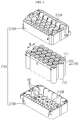
- FIG. 1 is a perspective view schematically showing a battery module manufactured by a manufacturing apparatus according to an embodiment of the present disclosure.
- FIG. 2 is an exploded perspective view schematically showing components of the battery module manufactured by the manufacturing apparatus according to an embodiment of the present disclosure.
- FIG. 3 is a partially sectioned view schematically showing an internal structure of a cylindrical battery cell, employed at the battery module of FIG. 2 .
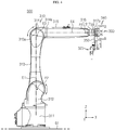
- FIG. 4 is a side view schematically showing the manufacturing apparatus according to an embodiment of the present disclosure.
- a manufacturing apparatus 300 includes a robot arm 310 to manufacture a battery module 200.
- the battery module 200 may include a plurality of cylindrical battery cells 100 and a module housing 210.
- the cylindrical battery cell 100 may include a cylindrical battery can 120 and an electrode assembly 140 ( FIG. 3 ) accommodated in the battery can 120.
- the battery can 120 may include a material with high electric conductivity.
- the battery can 120 may include an aluminum or copper material.
- the battery can 120 may be configured to stand up in a long shape in an upper and lower direction.
- the battery can 120 may have a cylindrical shape extending in the upper and lower direction.
- electrode terminals 111, 112 may be formed at upper and lower portions of the battery can 120, respectively. Specifically, a first electrode terminal 111 protruding in an upper direction may be formed on a flat circular upper surface at a top portion of the battery can 120, and a second electrode terminal 112 may be formed on a flat circular lower surface at a bottom portion of the battery can 120.
- the cylindrical battery cells 100 may be arranged in a plurality of columns and rows in a horizontal direction.
- the horizontal direction may refer to a direction parallel to the ground when the cylindrical battery cell 100 is placed on the ground and may also be referred to as at least one direction on a plane perpendicular to the upper and lower direction.
- the battery module 200 may include a plurality of cylindrical battery cells 100 arranged in four columns in the front and rear direction W and in seven or six rows in the left and right direction V.
- the electrode assembly 140 ( FIG. 3 ) may be formed in a structure where a positive electrode and a negative electrode are wound in a jelly-roll type with a separator being interposed therebetween.
- a positive electrode tab 170 may be attached to the positive electrode (not shown) and connected to the first electrode terminal 111 at the top portion of the battery can 120.
- a negative electrode tab (not shown) may be attached to the negative electrode (not shown) and connected to the second electrode terminal 112 at the bottom portion of the battery can 120.
- a top cap is formed at the cylindrical battery cell 100 in a protruding form to form the electrode terminal 111, and a portion of the top cap is perforated when an internal gas reaches a specific air pressure or higher.
- the cylindrical battery cell 100 may include a safety element 122 (for example, a positive temperature coefficient (PTC) element, a thermal cutoff (TCO), or the like) for blocking a current by greatly increasing a battery resistance when the temperature inside the battery cell rises.
- a safety element 122 for example, a positive temperature coefficient (PTC) element, a thermal cutoff (TCO), or the like
- the cylindrical battery cell 100 may have a safety vent structure 130 that has a downwardly protruding shape in a normal state but protrudes and ruptures to exhaust gas when the pressure inside the battery rises.
- the battery module 200 according to the present disclosure is not limited to the aforementioned cylindrical battery cell 100, and various cylindrical battery cell 100 known at the time of filing of this application may be employed.
- the module housing 210 may include an upper case 210A and a lower case 210B.
- the upper case 210A and the lower case 210B of the module housing 210 may include accommodation portions 212A, 212B for accommodating the cylindrical battery cell 100 therein, respectively.
- the accommodation portions 212A, 212B may have a plurality of hollow H2 formed to surround outer surfaces of the cylindrical battery cells 100.
- the module housing 210 may include a first outer wall 210a, a second outer wall 210b, a third outer wall 210c and a fourth outer wall 210d configured to form an inner space and provided at front, rear, left and right sides.
- the robot arm 310 may include a pillar portion 311, a first connection portion 312, a second connection portion 313, a third connection portion 314, a fourth connection portion 315, a rotary driving unit 316 ( FIG. 7 ), and a driving shaft 317.
- the pillar portion 311 may be a portion connected to a bottom surface on which the robot arm 310 is installed.
- the pillar portion 311 may be configured to allow the first connection portion 312 of the robot arm 310 to rotate based on a rotary shaft E1 in the upper and lower directions (a Z-axis direction).
- the pillar portion 311 may incorporate an electric motor (not shown).
- first connection portion 312 may be connected to an upper portion of the pillar portion 311.
- first connection portion 312 may be configured to move up and down a terminal portion (a top portion) 313a of the second connection portion 313 at a side corresponding to a direction where the first connection portion 312 is located.
- the first connection portion 312 may be connected to one end (a bottom portion) of the second connection portion 313.
- the first connection portion 312 may have an electric motor (not shown) to rotate the second connection portion 313 based on a rotary shaft E2 in a Y-axis direction.
- the second connection portion 313 may be configured to move up and down a terminal portion 314a of the third connection portion 314 at a side corresponding to a direction where the second connection portion 313 is located. To this end, the second connection portion 313 may be connected to one end of the third connection portion 314. Further, the second connection portion 313 may have an electric motor (not shown) to rotate the third connection portion 314 based on a rotary shaft E3 in the Y-axis direction.
- the third connection portion 314 may be connected to one end of the fourth connection portion 315. Further, the third connection portion 314 may have an electric motor (not shown) to rotate the fourth connection portion 315 based on a rotary shaft E4 in an X-axis direction.
- connection portion 315 may be connected to both sides (see 316 of FIG. 7 ) of the rotary driving unit 316.
- the fourth connection portion 315 may have an electric motor (not shown) to rotate the rotary driving unit 316 based on a rotary shaft E5 in the Y-axis direction.
- the manufacturing apparatus 300 of the present disclosure may include a central control unit (not shown).
- the central control unit may be configured to control the rotation of the first connection portion 312, the second connection portion 313, the third connection portion 314 and the fourth connection portion 315.
- the central control unit may be configured to control the operation of the driving shaft 317, the rotary driving unit 316, a first gripper 320, a second gripper 330 and a third gripper 340, explained later.
- the central control unit may be connected to a manipulation unit directly controlled by a worker.
- the central control unit may be operated according to a program including execution instructions of the robot arm required for the manufacturing process.
- the rotary driving unit 316 may be configured to move a terminal portion 317a of the driving shaft 317 upward or downward. Further, the rotary driving unit 316 may be shaped such that one end of the driving shaft 317 is inserted therein.
- the driving shaft 317 may be configured to rotate based on a rotary shaft E6 in the X-axis direction. Namely, the driving shaft 317 may move in two directions such that the terminal portion 317a moves in the upper and lower direction (the Z-axis direction) and in the clockwise or counterclockwise direction based on the X-axis direction.
- FIG. 5 is a partial perspective view schematically showing a portion of the manufacturing apparatus according to an embodiment of the present disclosure.
- the robot arm 310 may include a first gripper 320, a second gripper 330 and a third gripper 340.
- the first gripper 320 may be configured to hold or release the plurality of cylindrical battery cells 100.
- the second gripper 330 may be configured to hold or release the upper case 210A.
- the third gripper 340 may be configured to hold or release the lower case 210B.
- the robot arm 310 may include a disk 350 to which the first gripper 320, the second gripper 330 and the third gripper 340 are mounted.
- the disk 350 may have a plate shape with upper and lower surfaces 350a, 350b relatively broader than side surfaces thereof.
- a terminal portion of the driving shaft 317 in an axial direction may be connected to one broad surface 350a of the disk 350 via a coupling member 352.
- the driving shaft 317 may be configured to rotate based on the rotary shaft E6 in the X-axis direction of FIG. 4 so that the disk 350 is rotated. Further, the terminal portion of the driving shaft 317 moves along the rotary shaft E5 in the upper and lower direction (the Z-axis direction), and the broad upper and lower surfaces 350a, 350b of the disk 350 may be shaped to stand up in a direction perpendicular to the ground G1 or located in parallel to the ground G1.
- the rotating directions of the first connection portion 312, the second connection portion 313, the third connection portion 314, the fourth connection portion 315, the rotary driving unit 316 and the driving shaft 317 are not limited to the X-axis direction, Y-axis direction or the Z-axis direction, but depending on the situation, whenever the locations of the first connection portion 312, the second connection portion 313, the third connection portion 314, the fourth connection portion 315, the rotary driving unit 316 and the driving shaft 317 of the robot arm 310 are changed, the rotating directions of the components may be changed three-dimensionally.
- the first gripper 320 may include a plurality of first tong units 321, a plurality of first tong driving units 323, and a fixing frame 325.
- the plurality of first tong units 321 may be configured to hold or release the plurality of cylindrical battery cells 100, respectively.
- the first tong unit 321 may include a pair of fingers 321a, 321b extending in a longitudinal direction.
- an upper portion of the pair of fingers 321a, 321b in the longitudinal direction may be connected to the first tong driving unit 323.
- a lower portion of the pair of fingers 321a, 321b may be configured to hold or release one cylindrical battery cell 100.
- a dented groove H1 dented in an outer direction may be formed at an inner side of the first tong unit 321 facing the cylindrical battery cell 100 so as not to press a top portion of the cylindrical battery cell 100.
- the top portion of the cylindrical battery cell 100 is a region where components such as a safety element and a safety vent structure easily damaged or defected even by a weak impact are located, and these components may be damaged just by a pressing force of the first tong unit 321 for holding the top portion of the cylindrical battery cell 100.
- the first tong unit 321 may include a pair of fingers 321a, 321b.
- dented grooves H1 dented in the outer direction may be formed at inner sides of the pair of fingers 321a, 321b facing the top portion of the cylindrical battery cell 100.
- the dented groove H1 is formed at the first tong unit 321 of the present disclosure, it is possible to prevent the top portion of the cylindrical battery cell 100 from being pressed while the first tong unit 321 picks and holds the cylindrical battery cell 100, thereby reducing damage or defect of the safety element 122 and the safety vent structure 130 of the cylindrical battery cell 100.
- the first tong driving unit 323 may be configured to control the holding and releasing operation of each of plurality of first tong units 321.
- the first tong driving unit 323 may have a pneumatic cylinder 324.
- a cylinder (not shown) of the pneumatic cylinder 324 may be connected to the top portion of each of the plurality of first tong units 321.
- the pneumatic cylinder 324 may have an injection hole 324c through which air is injected or sucked.
- the cylinder may move so that two fingers 321a, 321b of the first tong unit 321 become farther from each other, and if air is sucked from the injection hole, the cylinder may move so that the pair of fingers 321a, 321b of the first tong unit 321 become closer to each other.
- FIG. 6 is an exploded perspective view schematically showing a compressor and a first gripper, employed at the manufacturing apparatus according to an embodiment of the present disclosure.
- a compressor and a first gripper employed at the manufacturing apparatus according to an embodiment of the present disclosure.
- an air hose for connecting the air discharge hole of the compressor 390 and the injection hole of the pneumatic cylinder is not depicted.
- the manufacturing apparatus 300 of the present disclosure may include a compressor 390 configured to supply a compressed air to the injection hole 324c of the pneumatic cylinder 324.
- the compressor 390 may suck an external air, compress the external air and supply the compressed air to the injection hole 324c of the pneumatic cylinder 324 through an air discharge hole 391.
- the compressor 390 may have separate injection holes 392, 393 formed to supply the compressed air to a pneumatic cylinder 334 ( FIG. 8 ) of the second gripper 330 and a pneumatic cylinder 344 ( FIG. 8 ) of the third gripper 340, explained later.
- the fixing frame 325 may be coupled to the disk 350.
- the fixing frame 325 may be connected to the plurality of first tong driving units 323.
- the fixing frame 325 may include a movable bar 326, a fixing member 325b and an elastic member 327.
- the movable bar 326 may have a body portion 326a with an outer side to which the first tong driving unit 323 is mounted, and a bolt 326b coupled to one side of the body portion 326a.
- the body portion 326a of the movable bar 326 may be spaced apart from one broad surface 350a of the disk 350 by a predetermined distance.
- the first tong driving unit 323 may be mounted to an outer side of the body portion 326a.
- a bolt 326b standing upright may be formed at a top of the body portion 326a.
- the fixing member 325b when viewed in the F direction, may have a plate shape extending in a direction perpendicular to one broad surface 350a of the disk 350.
- both ends 325b1, 325b2 of the fixing member 325b may be bent in the upper direction and bent again in the left and right direction.
- the fixing member 325b may have a plurality of guide holes H3 through which the bolt 326b is movably provided in the upper and lower direction so as to guide the movement of the bolt 326b of the movable bar 326 in the longitudinal direction.
- the guide hole H3 FIG. 5
- the fixing member 325b may be positioned at one broad surface 350a of the disk 350 to extend perpendicular to one broad surface 350a of the disk 350. Further, a portion (an inner portion) of the fixing member 325b may be coupled to the disk 350. In addition, seven guide holes H3 may be formed in the fixing member 325b. Also, seven bolts 326b of the first tong driving unit 323 may be inserted into the seven guide holes H3, respectively.
- a head of the bolt 326b may be blocked at the periphery of the guide hole H3 so that the first tong driving unit 323 may have a fixed shape. That is, the guide hole H3 may have a smaller size than the head of the bolt 326b.
- the elastic member 327 may be configured to apply a predetermined force to the movable bar 326 in an upper direction and/or in a lower direction.
- the elastic member 327 may be a spring.
- the spring may be inserted into a shaft portion of the bolt 326b.
- the spring may be located between the lower portion of the fixing member 325b and the movable bar 326a of the first tong driving unit 323.
- the elastic member 327 may be configured to apply a predetermined force in the lower direction. That is, the elastic member 327 may be formed to buffer the force in the upper direction S received by the first tong unit 321. Further, the elastic member 327 may prevent the bolt 326b of the movable bar 326 from moving upward over a predetermined height even with a small force.
- the fixing frame 325 is configured such that the movable bar 326 connected to the first tong driving unit 323 is elastically movable in the longitudinal direction (the upper direction) of the bolt 326b by using the elastic member 327, the elastic member 327 of the fixing frame 325 may absorb (buffer) the impact generated while the first gripper 320 receives the cylindrical battery cell 100 in the accommodation portion 212B of the lower case 210B. That is, the manufacturing apparatus 300 of the present disclosure may reduce the impact applied to the cylindrical battery cell 100 during the manufacturing process, thereby minimizing the defect of the battery cells 100 of the battery module 200.
- the fixing frame 325 may include an erroneous assembling sensor unit 328 configured to detect erroneous assembling while the first tong unit 321 is inserting the cylindrical battery cell 100 into the hollow formed at the lower case 210B.
- the erroneous assembling sensor unit 328 may include a laser sensor 328s.
- the laser sensor 328s may include a light emission portion 328s1 for outputting a laser and a light receiving portion 328s2 configured to detect a laser output from the light emission portion 328s1.
- the laser sensor 328s may be formed at the fixing member 325b to detect whether the bolt 326b of the movable bar 326 is moved upward. More specifically, the light emission portion 328s1 and the light receiving portion 328s2 of the laser sensor 328s may be formed at both ends of the fixing member 325b, respectively.
- the laser sensor 328s may detect the situation where the laser L1 has not reached the light receiving portion 328s2.
- seven movable bars 326 may be mounted to the fixing member 325b.
- the seven bolts 326b of the seven movable bars 326 may be inserted into seven guide holes H3 ( FIG. 6 ) formed in the fixing member 325b.
- the light emission portion 328s1 and the light receiving portion 328s2 of the laser sensor 328s may be formed at both ends 325b1, 325b2 in a direction along which the guide holes H3 of the fixing member 325b are arranged, respectively.
- the laser sensor 328s may be positioned to face the light emission portion 328s1 and the light receiving portion 328s2 in order to detect whether the bolt 326b of the movable bar 326 is moved upward.
- the fixing frame 325 includes the erroneous assembling sensor unit 328, it is possible to detect erroneous assembling while the cylindrical battery cell 100 is being inserted into the hollow formed at the lower case 210B. Thus, it is possible to prevent the cylindrical battery cell 100 from being exploded or ignited due to an impact that may occur since the plurality of cylindrical battery cells 100 are erroneously assembled. Further, the manufacturing apparatus 300 has an effect of reducing the defects of the plurality of cylindrical battery cells 100.
- FIG. 7 is a partially sectioned view schematically showing another operation of the manufacturing apparatus according to an embodiment of the present disclosure.
- FIG. 8 is a partially sectioned view schematically showing another operation of the manufacturing apparatus according to an embodiment of the present disclosure.
- FIG. 7 shows a situation where the robot arm 310 moves the upper case 210A of the module housing 210 to the upper portion of the lower case 210A by using the second gripper 330.
- the second gripper 330 may include a second tong unit 331, a second tong driving unit 333, and a pressing member 336.
- the second tong unit 331 may include a pressing plate 331a and a movable shaft 331b. More specifically, the pressing plate 331a may be configured to press both sides of the upper case 210A.
- the second tong unit 331 when viewed in the F direction, may include two pressing plates 331a positioned at both sides of the upper case 210A of the battery module 200 in the horizontal direction (the left and right direction).
- the pressing plates 331a may be configured to press both sides of the upper case 210A in the left and right direction by the movement of the movable shaft 331b.
- the second tong unit 331 may include two movable shafts 331b extending long in a direction parallel to one broad surface 350a of the disk 350. Also, an outer terminal portion of the movable shaft 331b may be coupled to the pressing plate 331a, and an inner terminal portion (not shown) thereof may be connected to the second tong driving unit 333.
- the second tong driving unit 333 may include a pneumatic cylinder 334.
- a cylinder (not shown) of the pneumatic cylinder 334 may be connected to the movable shaft 331b of the second tong unit 331.
- the pneumatic cylinder 334 may have injection holes (not shown) through which air is injected or sucked. If air is injected into one of the two injection holes, two pressing plates 331a of the second tong unit 331 may move farther from each other, and if air is sucked from the injection hole, two pressing plates 331a of the second tong unit 331 may move closer to each other.
- the movable shaft 331b may be configured such that the plurality of pressing plates 331a may move in a direction along which they become closer to each other or farther from each other.
- the second tong unit 331 may include two movable shafts 331b.
- the two movable shafts 331b may be configured such that the plurality of pressing plates 331a may move closer to each other or farther from each other.
- At least one contact member 331c having a shape protruding from the inner surface of the pressing plate 331a toward the upper case 210A may be formed at an inner surface of the pressing plate 331a facing the outer surface the upper case 210A.
- the terms indicating directions such as front, rear, left, right, upper and lower may vary depending on the position of an observer or the shape of an object.
- the front, rear, left, right, upper and lower directions are distinguished based on the case where viewed in the F direction.
- the second tong unit 331 may include two pressing plates 331a.
- two contact members 331c having a shape protruding toward the upper case 210A may be formed at inner surfaces of the two pressing plates 331a, respectively.
- the contact member 331c may be formed at a position where the contact member 331c may avoid pressing a structure or component such as a protrusion formed on the outer wall of the upper case 210A.
- the contact member 331c is formed at the pressing plate 331a of the second tong unit 331, it is possible to prevent the upper case 210A from being damaged or dropped since the second gripper 330 presses an inappropriate site while holding the upper case 210A.
- the second gripper 330 may include a pressing member 336 configured to press the upper case 210A toward the lower case 210B.
- the pressing member 336 may be connected to the other surface (the lower surface) 350b of the disk 350. Further, the pressing member 336 may be configured to protrusively extend in a direction perpendicular to the lower surface 350b that is relatively broader than the horizontal side surface of the disk 350.
- two pressing members 336 may be coupled to the lower surface 350b of the disk 350.
- the pressing member 336 may have a bar shape whose both longitudinal ends are bent upward.
- a buffer pad 335 having a soft material whose volume is easily changed may be formed at the lower portion of the pressing member 336.
- the movable shaft 331b of the second tong unit 331 may be positioned between both bent ends of the pressing member 336.
- two pressing members 336 may be formed at the lower surface 350b of the disk 350.
- the movable shaft 331b of the second tong unit 331 may be positioned to penetrate through the open center of the two pressing members 336, respectively.
- the second gripper 330 since the second gripper 330 includes the pressing member 336 configured to press the upper case 210A toward the lower case 210B, it is possible to help that the upper case 210A is perfectly coupled to the upper portion of the lower case 210B. Moreover, since the pressing member 336 may press the upper case 210A downward when the second tong unit 331 places the upper case 210A on the upper portion of the lower case 210B, the coupling work may be performed efficiently.
- the third gripper 340 may include a third tong unit, at least one third tong driving unit 343, and a hook 341c.
- the third tong unit may include a plurality of finger units 341a and a pressing bar 341b connected to a terminal portion of the finger unit 341a in a direction (a lower direction) away from the disk 350.
- both ends of the plurality of finger units 341a may be bent downward.
- the plurality of finger units 341a may be moved closer to each other or farther from each other.
- the pressing bar 341b may be formed to extend lone along the outer surface of the lower case 210B to press both horizontal sides of the lower case 210B.
- the third tong driving unit 343 may be configured to control the operation of the finger unit 341a.
- the third tong driving unit 343 may include a pneumatic cylinder 344.
- a cylinder (not shown) of the pneumatic cylinder 344 may be connected to one end of finger unit 341a of the third tong unit 341.
- the pneumatic cylinder 344 may have an injection hole 344b through which air is injected or sucked. Further, if air is injected into the injection hole 344b, two finger units 341a of the third tong unit may move farther from each other, and if air is sucked from the injection hole 344b, two finger units 341a of the third tong unit may move closer to each other.
- the hook 341c may also be connected to a lower portion of the pressing bar 341b (an end away from the disk 350). Specifically, the hook 341c may protrusively extend in the shape of the hook 341c from the pressing bar 341b toward the lower case 210B (in a direction closer to the two finger unit 341a) so that a portion of the hook 341c contacts the lower surface 210B1 of the lower case 210B.
- two hooks 341c may be formed at both longitudinal ends of the pressing bar 341b, respectively. Moreover, the hook 341c may be positioned such that the pressing bar 341b presses the outer surface of the lower case 210B and simultaneously a sharp portion of the hook 341c contacts the lower surface 210B1 of the lower case 210B.
- the pressing bar 341b may pick and hold the lower case 210B while pressing both sides of the lower case 210B and simultaneously the hook 341c may support the lower surface 210B1 of the lower case 210B upward, thereby effectively preventing accidents such as a case where the third tong driving unit 343 drops the lower case 210B.
- an arrangement unit 380 configured to evenly arrange the inserted heights of the plurality of cylindrical battery cells 100 accommodated in the lower case 210B may be formed at the other surface 350b of the disk 350.
- the arrangement unit 380 may have a pressing surface 380a configured to press the upper portion of the plurality of cylindrical battery cells 100 ( FIG. 2 ) accommodated in the lower case 210B ( FIG. 2 ) downward.
- the arrangement unit 380 may be located in a direction corresponding to the direction in which the fixing frame 325 is located. That is, if the fixing frame 325 is located at one side surface 350a (an upper surface) of the disk 350, the arrangement unit 380 may be located at the other side surface 350b (a lower surface) of the disk 350.
- the arrangement unit 380 may be formed at the other side surface 350b of the disk 350.
- the arrangement unit 380 may have a pressing surface 380a with a size corresponding to the upper surface of the lower case 210B. Further, the pressing surface 380a may be configured to press the upper portion of the plurality of cylindrical battery cells 100 downward.
- the present disclosure provides a method of manufacturing the battery module 200 by using the manufacturing apparatus 300.
- the manufacturing method may include a process in which the first gripper 320 picks and holds a plurality of cylindrical battery cells 100 arranged in one direction, a process in which the first gripper 320 inserts the plurality of cylindrical battery cells 100 into the hollows H2 formed at the lower case 210B and then releases the plurality of cylindrical battery cells 100, a process in which the second gripper 330 picks and holds the upper case 210A, a process in which the second gripper 330 places the upper case 210A at the upper portion of the lower case 210B and presses the upper case 210A onto the lower case 210B, a process in which the third gripper 340 picks and holds the lower case 210B to which the upper case 210A is mounted, and a process in which the robot arm 310 moves the assembled battery module 200 taken by the third gripper 340 to a set location.
- the first gripper 320 moves to the upper portion of the plurality of cylindrical battery cells 100 arranged in one direction, and then the first tong unit 321a of the first gripper 320 may move downward and pick and hold the bodies of the plurality of cylindrical battery cells 100.
- the robot arm 310 may move the first connection portion 312, the second connection portion 313, the third connection portion 314, the fourth connection portion 315, the rotary driving unit 316 ( FIG. 7 ) and the driving shaft 317 such that the broad surface 350a of the disk 350 is arranged in the horizontal direction and the first gripper 320 is located at the lower portion of the disk 350.
- the robot arm 310 may move the first connection portion 312, the second connection portion 313, the third connection portion 314, the fourth connection portion 315, the rotary driving unit 316 ( FIG. 7 ) and the driving shaft 317 such that the first gripper 320, the second gripper 330 or the third gripper 340 is moved and rotated to an appropriate position.
- the present disclosure may provide a battery module 200 that is manufactured by the manufacturing apparatus 300.
- the present disclosure may provide a battery pack (not shown) including a plurality of battery modules 200.
- the battery pack may further include various devices for controlling charging and discharging of the plurality of cylindrical battery cells 100, such as a battery management system (BMS, not shown), a current sensor (not shown), a fuse (not shown), and the like.
- BMS battery management system
- a current sensor not shown
- a fuse not shown
- the battery module 200 according to the present disclosure may be applied to a vehicle such as an electric vehicle or a hybrid electric vehicle. That is, the vehicle according to the present disclosure may include the battery module 200.
- 300 manufacturing apparatus 310: robot arm 200: battery module 100: cylindrical battery cell 111, 112: electrode terminal 210: module housing 210A, 210B: upper case, lower case 320, 330, 340: first gripper, second gripper, third gripper 350: disk 317, 316: driving shaft, rotary driving unit 321, 331, 341: first tong unit, second tong unit, third tong unit 323, 333, 343: first tong driving unit, second tong driving unit, third tong driving unit 325: fixing frame H1: dented groove 326: movable bar 325b: fixing member 327: elastic member 328: erroneous assembling sensor unit 328s: laser sensor 331a, 331b: pressing plate, movable shaft 336: pressing member 341a, 341b, 341c: finger unit, pressing bar, hook
- the present disclosure relates to a manufacturing apparatus for manufacturing a battery module. Also, the present disclosure is available for industries related to electronic devices and vehicles equipped with the battery module manufactured by the manufacturing apparatus.
Landscapes
- Engineering & Computer Science (AREA)
- Robotics (AREA)
- Mechanical Engineering (AREA)
- Chemical & Material Sciences (AREA)
- Chemical Kinetics & Catalysis (AREA)
- Electrochemistry (AREA)
- General Chemical & Material Sciences (AREA)
- Manufacturing & Machinery (AREA)
- Physics & Mathematics (AREA)
- Optics & Photonics (AREA)
- Battery Mounting, Suspending (AREA)
- Manipulator (AREA)
Abstract
Description
- The present disclosure relates to a robot including a robot arm, and more particularly, to a manufacturing apparatus including a robot arm, which enhances production efficiency and allows automated production.
- The present application claims priority to Korean Patent Application No.
10-2018-0133815 filed on November 2, 2018 - Currently commercialized secondary batteries include nickel cadmium batteries, nickel hydrogen batteries, nickel zinc batteries, lithium secondary batteries, and the like. Among them, the lithium secondary battery has been spotlighted since it has almost no memory effect compared to nickel-based secondary batteries to ensure free charge and discharge and also has very low discharge rate and high energy density.
- The lithium secondary battery mainly uses a lithium-based oxide and a carbon material as a positive electrode active material and a negative electrode active material, respectively. The lithium secondary battery includes an electrode assembly, in which a positive electrode plate and a negative electrode plate respectively coated with the positive electrode active material and the negative electrode active material are arranged with a separator being interposed therebetween, and a cylindrical battery can serving as an exterior for sealing and accommodating the electrode assembly along with an electrolyte.
- Recently, the secondary battery is widely used in medium-sized and large-sized devices such as vehicles and power storage systems as well as small-sized devices such as portable electronic devices. When used in the medium-sized and large-sized devices, a large number of secondary batteries are electrically connected to increase capacity and power output.
- Meanwhile, in recent years, as the need for a large-capacity structure increases as well as utilization as an energy storage source, the demand for a battery pack in which a plurality of battery modules, each having a plurality of secondary batteries electrically connected in series and/or in parallel, are aggregated is increasing.
- In addition, the battery module generally includes a module housing made of plastic material in order to protect the plurality of secondary batteries from external impacts and also accommodate and store the plurality of secondary batteries. For example, an accommodation portion may be formed in the module housing as a separate space for accommodating the plurality of secondary batteries.
- However, the process of accommodating a plurality of cylindrical battery cells in the module housing is a cumbersome and difficult task, which is not easily performed by machine automation and thus generally performed manually by workers.
- Moreover, as a production automation system capable of greatly increasing the safety and production efficiency is widely used in recent years, industrial robots or the like put into each manufacturing process of the battery module are widely used.
- However, as a large number of industrial robots are required for each of various manufacturing processes of the battery module, manufacturing equipment costs have been increased sharply, which may it difficult to secure price competitiveness of products.
- The present disclosure is designed to solve the problems of the related art, and therefore the present disclosure is directed to providing a manufacturing apparatus including a robot arm, which may increase production efficiency and greatly reduce the size of manufacturing equipment.
- These and other objects and advantages of the present disclosure may be understood from the following detailed description and will become more fully apparent from the exemplary embodiments of the present disclosure. Also, it will be easily understood that the objects and advantages of the present disclosure may be realized by the means shown in the appended claims and combinations thereof.
- In one aspect of the present disclosure, there is provided a manufacturing apparatus, which comprises a robot arm to manufacture a battery module that includes a plurality of cylindrical battery cells and a module housing having an upper case and a lower case configured to accommodate the plurality of cylindrical battery cells,
wherein the robot arm includes: - a first gripper configured to hold or release the plurality of cylindrical battery cells;
- a second gripper configured to hold or release the upper case; and
- a third gripper configured to hold or release the lower case.
- Moreover, the robot arm may further include:
- a disk having a plate shape with upper and lower surfaces relatively broader than side surfaces thereof so that the first gripper, the second gripper and the third gripper are mounted thereto;
- a driving shaft having a longitudinal terminal portion rotatably connected to the disk to rotate the disk; and
- a rotary driving unit configured to move the terminal portion of the driving shaft in an upper direction or in a lower direction.
- In addition, the first gripper may include:
- a plurality of first tong units configured to hold or release the plurality of cylindrical battery cells, respectively;
- a plurality of first tong driving units respectively connected to ends of the plurality of first tong units and configured to control the holding and releasing operation of each of the plurality of first tong units; and
- a fixing frame connected to the plurality of first tong driving units and having a portion coupled to the disk.
- Further, a dented groove dented in an outer direction of the first tong unit not to press a top portion of the cylindrical battery cell may be formed at an inner side of the first tong unit facing the cylindrical battery cell.
- In addition, the fixing frame may include:
- a movable bar having a body portion with an outer side to which the first tong driving unit is mounted and a bolt coupled to one side of the body portion;
- a fixing member having a guide hole perforated such that a portion of the bolt is inserted therein to guide the movable bar to move in a longitudinal direction of the bolt; and
- an elastic member configured to apply a predetermined force to the movable bar in the longitudinal direction of the bolt.
- Moreover, the fixing frame may include an erroneous assembling sensor unit configured to detect erroneous assembling while the first tong unit is inserting the cylindrical battery cell into a hollow formed at the lower case.
- Also, the erroneous assembling sensor unit may include a laser sensor formed at the fixing member to detect whether the bolt of the movable bar is moved upward.
- Further, the second gripper may include:
- a second tong unit having a plurality of pressing plates configured to press both sides of the upper case and a movable shaft configured to move in a direction along which the plurality of pressing plates move closer to each other or farther from each other;
- at least one second tong driving unit configured to control a movement of the movable shaft; and
- a pressing member connected to the disk and configured to press the upper case toward the lower case.
- In addition, the third gripper may include:
- a third tong unit having a plurality of finger units of a bent shape configured to move closer to each other or farther from each other and a pressing bar connected to a terminal portion of the finger unit to press both horizontal sides of the lower case;
- at least one third tong driving unit configured to control an operation of the finger unit; and
- a hook connected to the pressing bar and configured to be hooked to a bottom portion of the lower case.
- Further, in another aspect of the present disclosure, there is also provided a manufacturing method, which manufactures a battery module by using the manufacturing apparatus.
- In addition, in another aspect of the present disclosure, there is also provided a battery module, which is manufactured by the manufacturing apparatus.
- According to an embodiment of the present disclosure, since the dented groove is formed at the first tong unit of the present disclosure, it is possible to effectively prevent the cylindrical battery cell included in the battery module from being damaged or defected while the first tong unit picks and holds the top portion of the cylindrical battery cell.
- Also, according to an embodiment of the present disclosure, since the fixing frame includes a movable bar elastically movable in the longitudinal direction of the bolt by using an elastic member connected to the first tong driving unit, the movable bar of the fixing frame may elastically absorb the impact generated while the first gripper receives the cylindrical battery cell in the accommodation portion of the lower case. That is, the manufacturing apparatus of the present disclosure may reduce the impact applied to the cylindrical battery cell during the manufacturing process, thereby minimizing the defect of the battery cells of the battery module.
- In addition, according to an embodiment of the present disclosure, since the fixing frame includes the erroneous assembling sensor unit, it is possible to detect erroneous assembling while the cylindrical battery cell is being inserted into the hollow formed at the lower case. By doing so, it is possible to prevent the cylindrical battery cell from being exploded or ignited due to an impact that may occur since the plurality of cylindrical battery cells are erroneously assembled. Further, the manufacturing apparatus has an effect of reducing the defects of the plurality of cylindrical battery cells.
- Moreover, according to an embodiment of the present disclosure, since the second gripper includes the pressing member configured to press the upper case toward the lower case, it is possible to help that the upper case is perfectly coupled to the upper portion of the lower case. Moreover, since the pressing member may press the upper case downward when the second tong unit places the upper case on the upper portion of the lower case, the coupling work may be performed efficiently.
- In addition, according to an embodiment of the present disclosure, since the third gripper includes the hook formed at the pressing bar, the pressing bar may pick and hold the lower case while pressing both sides of the lower case and simultaneously the hook may support the lower surface of the lower case upward, thereby effectively preventing accidents such as a case where the third tong driving unit drops the lower case.
- The accompanying drawings illustrate a preferred embodiment of the present disclosure and together with the foregoing disclosure, serve to provide further understanding of the technical features of the present disclosure, and thus, the present disclosure is not construed as being limited to the drawing.
-
FIG. 1 is a perspective view schematically showing a battery module manufactured by a manufacturing apparatus according to an embodiment of the present disclosure. -
FIG. 2 is an exploded perspective view schematically showing components of the battery module manufactured by the manufacturing apparatus according to an embodiment of the present disclosure. -
FIG. 3 is a partially sectioned view schematically showing an internal structure of a cylindrical battery cell, employed at the battery module ofFIG. 2 . -
FIG. 4 is a side view schematically showing the manufacturing apparatus according to an embodiment of the present disclosure. -
FIG. 5 is a partial perspective view schematically showing a portion of the manufacturing apparatus according to an embodiment of the present disclosure. -
FIG. 6 is an exploded perspective view schematically showing a compressor and a first gripper, employed at the manufacturing apparatus according to an embodiment of the present disclosure. -
FIG. 7 is a partially sectioned view schematically showing another operation of the manufacturing apparatus according to an embodiment of the present disclosure. -
FIG. 8 is a partially sectioned view schematically showing another operation of the manufacturing apparatus according to an embodiment of the present disclosure. - Hereinafter, preferred embodiments of the present disclosure will be described in detail with reference to the accompanying drawings. Prior to the description, it should be understood that the terms used in the specification and the appended claims should not be construed as limited to general and dictionary meanings, but interpreted based on the meanings and concepts corresponding to technical aspects of the present disclosure on the basis of the principle that the inventor is allowed to define terms appropriately for the best explanation.
- Therefore, the description proposed herein is just a preferable example for the purpose of illustrations only, not intended to limit the scope of the disclosure, so it should be understood that other equivalents and modifications could be made thereto without departing from the scope of the disclosure.
-
FIG. 1 is a perspective view schematically showing a battery module manufactured by a manufacturing apparatus according to an embodiment of the present disclosure.FIG. 2 is an exploded perspective view schematically showing components of the battery module manufactured by the manufacturing apparatus according to an embodiment of the present disclosure.FIG. 3 is a partially sectioned view schematically showing an internal structure of a cylindrical battery cell, employed at the battery module ofFIG. 2 .FIG. 4 is a side view schematically showing the manufacturing apparatus according to an embodiment of the present disclosure. - Referring to
FIGS. 1 to 4 , amanufacturing apparatus 300 according to an embodiment of the present disclosure includes arobot arm 310 to manufacture abattery module 200. - Here, the
battery module 200 may include a plurality ofcylindrical battery cells 100 and amodule housing 210. Specifically, thecylindrical battery cell 100 may include a cylindrical battery can 120 and an electrode assembly 140 (FIG. 3 ) accommodated in the battery can 120. - Here, the battery can 120 may include a material with high electric conductivity. For example, the battery can 120 may include an aluminum or copper material.
- In addition, the battery can 120 may be configured to stand up in a long shape in an upper and lower direction. Also, the battery can 120 may have a cylindrical shape extending in the upper and lower direction. Moreover,
electrode terminals first electrode terminal 111 protruding in an upper direction may be formed on a flat circular upper surface at a top portion of the battery can 120, and asecond electrode terminal 112 may be formed on a flat circular lower surface at a bottom portion of the battery can 120. - Further, the
cylindrical battery cells 100 may be arranged in a plurality of columns and rows in a horizontal direction. Here, the horizontal direction may refer to a direction parallel to the ground when thecylindrical battery cell 100 is placed on the ground and may also be referred to as at least one direction on a plane perpendicular to the upper and lower direction. - For example, as shown in
FIG. 2 , thebattery module 200 may include a plurality ofcylindrical battery cells 100 arranged in four columns in the front and rear direction W and in seven or six rows in the left and right direction V. - In addition, the electrode assembly 140 (
FIG. 3 ) may be formed in a structure where a positive electrode and a negative electrode are wound in a jelly-roll type with a separator being interposed therebetween. Apositive electrode tab 170 may be attached to the positive electrode (not shown) and connected to thefirst electrode terminal 111 at the top portion of the battery can 120. A negative electrode tab (not shown) may be attached to the negative electrode (not shown) and connected to thesecond electrode terminal 112 at the bottom portion of the battery can 120. - Referring to
FIG. 3 again along withFIG. 2 , a top cap is formed at thecylindrical battery cell 100 in a protruding form to form theelectrode terminal 111, and a portion of the top cap is perforated when an internal gas reaches a specific air pressure or higher. - In addition, the
cylindrical battery cell 100 may include a safety element 122 (for example, a positive temperature coefficient (PTC) element, a thermal cutoff (TCO), or the like) for blocking a current by greatly increasing a battery resistance when the temperature inside the battery cell rises. Also, thecylindrical battery cell 100 may have asafety vent structure 130 that has a downwardly protruding shape in a normal state but protrudes and ruptures to exhaust gas when the pressure inside the battery rises. - However, the
battery module 200 according to the present disclosure is not limited to the aforementionedcylindrical battery cell 100, and variouscylindrical battery cell 100 known at the time of filing of this application may be employed. - Meanwhile, the
module housing 210 may include anupper case 210A and alower case 210B. - In addition, the
upper case 210A and thelower case 210B of themodule housing 210 may includeaccommodation portions cylindrical battery cell 100 therein, respectively. Specifically, theaccommodation portions cylindrical battery cells 100. - In addition, the
module housing 210 may include a firstouter wall 210a, a secondouter wall 210b, a thirdouter wall 210c and a fourthouter wall 210d configured to form an inner space and provided at front, rear, left and right sides. - Referring to
FIG. 4 again, therobot arm 310 may include apillar portion 311, afirst connection portion 312, asecond connection portion 313, athird connection portion 314, afourth connection portion 315, a rotary driving unit 316 (FIG. 7 ), and a drivingshaft 317. - Specifically, the
pillar portion 311 may be a portion connected to a bottom surface on which therobot arm 310 is installed. In addition, thepillar portion 311 may be configured to allow thefirst connection portion 312 of therobot arm 310 to rotate based on a rotary shaft E1 in the upper and lower directions (a Z-axis direction). For example, thepillar portion 311 may incorporate an electric motor (not shown). - Further, the
first connection portion 312 may be connected to an upper portion of thepillar portion 311. In addition, thefirst connection portion 312 may be configured to move up and down a terminal portion (a top portion) 313a of thesecond connection portion 313 at a side corresponding to a direction where thefirst connection portion 312 is located. To this end, thefirst connection portion 312 may be connected to one end (a bottom portion) of thesecond connection portion 313. Further, thefirst connection portion 312 may have an electric motor (not shown) to rotate thesecond connection portion 313 based on a rotary shaft E2 in a Y-axis direction. - In addition, the
second connection portion 313 may be configured to move up and down a terminal portion 314a of thethird connection portion 314 at a side corresponding to a direction where thesecond connection portion 313 is located. To this end, thesecond connection portion 313 may be connected to one end of thethird connection portion 314. Further, thesecond connection portion 313 may have an electric motor (not shown) to rotate thethird connection portion 314 based on a rotary shaft E3 in the Y-axis direction. - Also, the
third connection portion 314 may be connected to one end of thefourth connection portion 315. Further, thethird connection portion 314 may have an electric motor (not shown) to rotate thefourth connection portion 315 based on a rotary shaft E4 in an X-axis direction. - Further, the
fourth connection portion 315 may be connected to both sides (see 316 ofFIG. 7 ) of therotary driving unit 316. Thefourth connection portion 315 may have an electric motor (not shown) to rotate therotary driving unit 316 based on a rotary shaft E5 in the Y-axis direction. - Moreover, the
manufacturing apparatus 300 of the present disclosure may include a central control unit (not shown). The central control unit may be configured to control the rotation of thefirst connection portion 312, thesecond connection portion 313, thethird connection portion 314 and thefourth connection portion 315. In addition, the central control unit may be configured to control the operation of the drivingshaft 317, therotary driving unit 316, afirst gripper 320, asecond gripper 330 and athird gripper 340, explained later. Further, the central control unit may be connected to a manipulation unit directly controlled by a worker. In addition, the central control unit may be operated according to a program including execution instructions of the robot arm required for the manufacturing process. - In addition, the
rotary driving unit 316 may be configured to move aterminal portion 317a of the drivingshaft 317 upward or downward. Further, therotary driving unit 316 may be shaped such that one end of the drivingshaft 317 is inserted therein. - In addition, the driving
shaft 317 may be configured to rotate based on a rotary shaft E6 in the X-axis direction. Namely, the drivingshaft 317 may move in two directions such that theterminal portion 317a moves in the upper and lower direction (the Z-axis direction) and in the clockwise or counterclockwise direction based on the X-axis direction. -
FIG. 5 is a partial perspective view schematically showing a portion of the manufacturing apparatus according to an embodiment of the present disclosure. - Referring to
FIG. 5 along withFIGS. 1 and4 , therobot arm 310 may include afirst gripper 320, asecond gripper 330 and athird gripper 340. In addition, thefirst gripper 320 may be configured to hold or release the plurality ofcylindrical battery cells 100. Further, thesecond gripper 330 may be configured to hold or release theupper case 210A. In addition, thethird gripper 340 may be configured to hold or release thelower case 210B. - Further, the
robot arm 310 may include adisk 350 to which thefirst gripper 320, thesecond gripper 330 and thethird gripper 340 are mounted. Specifically, thedisk 350 may have a plate shape with upper andlower surfaces shaft 317 in an axial direction may be connected to onebroad surface 350a of thedisk 350 via acoupling member 352. - In addition, the driving
shaft 317 may be configured to rotate based on the rotary shaft E6 in the X-axis direction ofFIG. 4 so that thedisk 350 is rotated. Further, the terminal portion of the drivingshaft 317 moves along the rotary shaft E5 in the upper and lower direction (the Z-axis direction), and the broad upper andlower surfaces disk 350 may be shaped to stand up in a direction perpendicular to the ground G1 or located in parallel to the ground G1. - However, the rotating directions of the
first connection portion 312, thesecond connection portion 313, thethird connection portion 314, thefourth connection portion 315, therotary driving unit 316 and the drivingshaft 317 are not limited to the X-axis direction, Y-axis direction or the Z-axis direction, but depending on the situation, whenever the locations of thefirst connection portion 312, thesecond connection portion 313, thethird connection portion 314, thefourth connection portion 315, therotary driving unit 316 and the drivingshaft 317 of therobot arm 310 are changed, the rotating directions of the components may be changed three-dimensionally. - More specifically, the
first gripper 320 may include a plurality offirst tong units 321, a plurality of firsttong driving units 323, and a fixingframe 325. - Here, when viewed in an F direction of
FIG. 5 , the plurality offirst tong units 321 may be configured to hold or release the plurality ofcylindrical battery cells 100, respectively. Specifically, thefirst tong unit 321 may include a pair offingers fingers tong driving unit 323. Further, by the firsttong driving unit 323, a lower portion of the pair offingers cylindrical battery cell 100. Also, a dented groove H1 dented in an outer direction may be formed at an inner side of thefirst tong unit 321 facing thecylindrical battery cell 100 so as not to press a top portion of thecylindrical battery cell 100. - That is, the top portion of the
cylindrical battery cell 100 is a region where components such as a safety element and a safety vent structure easily damaged or defected even by a weak impact are located, and these components may be damaged just by a pressing force of thefirst tong unit 321 for holding the top portion of thecylindrical battery cell 100. - For example, as shown in
FIG. 5 , thefirst tong unit 321 may include a pair offingers fingers cylindrical battery cell 100. - Thus, according to this configuration of the present disclosure, since the dented groove H1 is formed at the
first tong unit 321 of the present disclosure, it is possible to prevent the top portion of thecylindrical battery cell 100 from being pressed while thefirst tong unit 321 picks and holds thecylindrical battery cell 100, thereby reducing damage or defect of thesafety element 122 and thesafety vent structure 130 of thecylindrical battery cell 100. - In addition, the first
tong driving unit 323 may be configured to control the holding and releasing operation of each of plurality offirst tong units 321. For example, the firsttong driving unit 323 may have apneumatic cylinder 324. Moreover, a cylinder (not shown) of thepneumatic cylinder 324 may be connected to the top portion of each of the plurality offirst tong units 321. Also, thepneumatic cylinder 324 may have aninjection hole 324c through which air is injected or sucked. Further, if air is injected into theinjection hole 324c, the cylinder may move so that twofingers first tong unit 321 become farther from each other, and if air is sucked from the injection hole, the cylinder may move so that the pair offingers first tong unit 321 become closer to each other. -
FIG. 6 is an exploded perspective view schematically showing a compressor and a first gripper, employed at the manufacturing apparatus according to an embodiment of the present disclosure. For convenience of description, an air hose for connecting the air discharge hole of thecompressor 390 and the injection hole of the pneumatic cylinder is not depicted. - Referring to
FIG. 6 along withFIG. 5 , themanufacturing apparatus 300 of the present disclosure may include acompressor 390 configured to supply a compressed air to theinjection hole 324c of thepneumatic cylinder 324. Specifically, thecompressor 390 may suck an external air, compress the external air and supply the compressed air to theinjection hole 324c of thepneumatic cylinder 324 through anair discharge hole 391. - Further, the
compressor 390 may have separate injection holes 392, 393 formed to supply the compressed air to a pneumatic cylinder 334 (FIG. 8 ) of thesecond gripper 330 and a pneumatic cylinder 344 (FIG. 8 ) of thethird gripper 340, explained later. - Meanwhile, a portion of the fixing
frame 325 may be coupled to thedisk 350. In addition, the fixingframe 325 may be connected to the plurality of firsttong driving units 323. - Specifically, the fixing
frame 325 may include amovable bar 326, a fixingmember 325b and anelastic member 327. Further, themovable bar 326 may have abody portion 326a with an outer side to which the firsttong driving unit 323 is mounted, and abolt 326b coupled to one side of thebody portion 326a. - For example, as shown in
FIG. 5 , thebody portion 326a of themovable bar 326 may be spaced apart from onebroad surface 350a of thedisk 350 by a predetermined distance. In addition, the firsttong driving unit 323 may be mounted to an outer side of thebody portion 326a. Further, abolt 326b standing upright may be formed at a top of thebody portion 326a. - Further, referring to
FIG. 6 along withFIG. 5 , when viewed in the F direction, the fixingmember 325b may have a plate shape extending in a direction perpendicular to onebroad surface 350a of thedisk 350. In addition, both ends 325b1, 325b2 of the fixingmember 325b may be bent in the upper direction and bent again in the left and right direction. Further, the fixingmember 325b may have a plurality of guide holes H3 through which thebolt 326b is movably provided in the upper and lower direction so as to guide the movement of thebolt 326b of themovable bar 326 in the longitudinal direction. Further, the guide hole H3 (FIG. 5 ) may be perforated in the longitudinal direction (the upper and lower direction) of thebolt 326b so that a portion of thebolt 326b is inserted therein. - For example, as shown in
FIG. 5 , the fixingmember 325b may be positioned at onebroad surface 350a of thedisk 350 to extend perpendicular to onebroad surface 350a of thedisk 350. Further, a portion (an inner portion) of the fixingmember 325b may be coupled to thedisk 350. In addition, seven guide holes H3 may be formed in the fixingmember 325b. Also, sevenbolts 326b of the firsttong driving unit 323 may be inserted into the seven guide holes H3, respectively. - Further, a head of the
bolt 326b may be blocked at the periphery of the guide hole H3 so that the firsttong driving unit 323 may have a fixed shape. That is, the guide hole H3 may have a smaller size than the head of thebolt 326b. - Moreover, the
elastic member 327 may be configured to apply a predetermined force to themovable bar 326 in an upper direction and/or in a lower direction. For example, as shown inFIG. 5 , theelastic member 327 may be a spring. In addition, the spring may be inserted into a shaft portion of thebolt 326b. Moreover, the spring may be located between the lower portion of the fixingmember 325b and themovable bar 326a of the firsttong driving unit 323. - Accordingly, as shown in
FIG. 6 , if thefirst tong unit 321 of thefirst gripper 320 receives a force in the upper direction S, the firsttong driving unit 323 connected to thefirst tong unit 321 is moved in the upper direction S, and at the same time, the firstmovable bar 326 connected to the firsttong driving unit 323 may also be moved in the upper direction S. In this case, theelastic member 327 may be configured to apply a predetermined force in the lower direction. That is, theelastic member 327 may be formed to buffer the force in the upper direction S received by thefirst tong unit 321. Further, theelastic member 327 may prevent thebolt 326b of themovable bar 326 from moving upward over a predetermined height even with a small force. - Thus, according to this configuration of the present disclosure, since the fixing
frame 325 is configured such that themovable bar 326 connected to the firsttong driving unit 323 is elastically movable in the longitudinal direction (the upper direction) of thebolt 326b by using theelastic member 327, theelastic member 327 of the fixingframe 325 may absorb (buffer) the impact generated while thefirst gripper 320 receives thecylindrical battery cell 100 in theaccommodation portion 212B of thelower case 210B. That is, themanufacturing apparatus 300 of the present disclosure may reduce the impact applied to thecylindrical battery cell 100 during the manufacturing process, thereby minimizing the defect of thebattery cells 100 of thebattery module 200. - Meanwhile, referring to
FIG. 5 again along withFIG. 2 , the fixingframe 325 may include an erroneousassembling sensor unit 328 configured to detect erroneous assembling while thefirst tong unit 321 is inserting thecylindrical battery cell 100 into the hollow formed at thelower case 210B. - Specifically, the erroneous
assembling sensor unit 328 may include alaser sensor 328s. In addition, thelaser sensor 328s may include a light emission portion 328s1 for outputting a laser and a light receiving portion 328s2 configured to detect a laser output from the light emission portion 328s1. Moreover, thelaser sensor 328s may be formed at the fixingmember 325b to detect whether thebolt 326b of themovable bar 326 is moved upward. More specifically, the light emission portion 328s1 and the light receiving portion 328s2 of thelaser sensor 328s may be formed at both ends of the fixingmember 325b, respectively. - In addition, if the laser L1 output from the light emission portion 328s1 does not reach the light receiving portion 328s2, namely if the
bolt 326b of themovable bar 326 moves upward to block the moving direction of the laser L1, thelaser sensor 328s may detect the situation where the laser L1 has not reached the light receiving portion 328s2. - For example, as shown in
FIG. 5 , sevenmovable bars 326 may be mounted to the fixingmember 325b. In addition, the sevenbolts 326b of the sevenmovable bars 326 may be inserted into seven guide holes H3 (FIG. 6 ) formed in the fixingmember 325b. Also, the light emission portion 328s1 and the light receiving portion 328s2 of thelaser sensor 328s may be formed at both ends 325b1, 325b2 in a direction along which the guide holes H3 of the fixingmember 325b are arranged, respectively. Further, thelaser sensor 328s may be positioned to face the light emission portion 328s1 and the light receiving portion 328s2 in order to detect whether thebolt 326b of themovable bar 326 is moved upward. - Thus, according to this configuration of the present disclosure, since the fixing
frame 325 includes the erroneousassembling sensor unit 328, it is possible to detect erroneous assembling while thecylindrical battery cell 100 is being inserted into the hollow formed at thelower case 210B. Thus, it is possible to prevent thecylindrical battery cell 100 from being exploded or ignited due to an impact that may occur since the plurality ofcylindrical battery cells 100 are erroneously assembled. Further, themanufacturing apparatus 300 has an effect of reducing the defects of the plurality ofcylindrical battery cells 100. -
FIG. 7 is a partially sectioned view schematically showing another operation of the manufacturing apparatus according to an embodiment of the present disclosure. Also,FIG. 8 is a partially sectioned view schematically showing another operation of the manufacturing apparatus according to an embodiment of the present disclosure. For reference,FIG. 7 shows a situation where therobot arm 310 moves theupper case 210A of themodule housing 210 to the upper portion of thelower case 210A by using thesecond gripper 330. - Referring to
FIGS. 7 and8 , thesecond gripper 330 may include asecond tong unit 331, a secondtong driving unit 333, and apressing member 336. - Specifically, the
second tong unit 331 may include apressing plate 331a and amovable shaft 331b. More specifically, thepressing plate 331a may be configured to press both sides of theupper case 210A. For example, as shown inFIG. 8 , when viewed in the F direction, thesecond tong unit 331 may include twopressing plates 331a positioned at both sides of theupper case 210A of thebattery module 200 in the horizontal direction (the left and right direction). Moreover, thepressing plates 331a may be configured to press both sides of theupper case 210A in the left and right direction by the movement of themovable shaft 331b. - In addition, the
second tong unit 331 may include twomovable shafts 331b extending long in a direction parallel to onebroad surface 350a of thedisk 350. Also, an outer terminal portion of themovable shaft 331b may be coupled to thepressing plate 331a, and an inner terminal portion (not shown) thereof may be connected to the secondtong driving unit 333. - For example, the second
tong driving unit 333 may include a pneumatic cylinder 334. Moreover, a cylinder (not shown) of the pneumatic cylinder 334 may be connected to themovable shaft 331b of thesecond tong unit 331. Further, the pneumatic cylinder 334 may have injection holes (not shown) through which air is injected or sucked. If air is injected into one of the two injection holes, twopressing plates 331a of thesecond tong unit 331 may move farther from each other, and if air is sucked from the injection hole, twopressing plates 331a of thesecond tong unit 331 may move closer to each other. - Moreover, the
movable shaft 331b may be configured such that the plurality ofpressing plates 331a may move in a direction along which they become closer to each other or farther from each other. - For example, as shown in
FIG. 8 , thesecond tong unit 331 may include twomovable shafts 331b. In addition, the twomovable shafts 331b may be configured such that the plurality ofpressing plates 331a may move closer to each other or farther from each other. - In addition, at least one
contact member 331c having a shape protruding from the inner surface of thepressing plate 331a toward theupper case 210A may be formed at an inner surface of thepressing plate 331a facing the outer surface theupper case 210A. - Meanwhile, the terms indicating directions such as front, rear, left, right, upper and lower may vary depending on the position of an observer or the shape of an object. However, in this specification, for convenience of description, the front, rear, left, right, upper and lower directions are distinguished based on the case where viewed in the F direction.
- For example, as shown in
FIG. 8 , thesecond tong unit 331 may include twopressing plates 331a. In addition, twocontact members 331c having a shape protruding toward theupper case 210A may be formed at inner surfaces of the twopressing plates 331a, respectively. Further, thecontact member 331c may be formed at a position where thecontact member 331c may avoid pressing a structure or component such as a protrusion formed on the outer wall of theupper case 210A. - Thus, according to this configuration of the present disclosure, since the
contact member 331c is formed at thepressing plate 331a of thesecond tong unit 331, it is possible to prevent theupper case 210A from being damaged or dropped since thesecond gripper 330 presses an inappropriate site while holding theupper case 210A. - In addition, the
second gripper 330 may include apressing member 336 configured to press theupper case 210A toward thelower case 210B. Specifically, the pressingmember 336 may be connected to the other surface (the lower surface) 350b of thedisk 350. Further, the pressingmember 336 may be configured to protrusively extend in a direction perpendicular to thelower surface 350b that is relatively broader than the horizontal side surface of thedisk 350. - For example, as shown in
FIG. 8 , two pressingmembers 336 may be coupled to thelower surface 350b of thedisk 350. In addition, the pressingmember 336 may have a bar shape whose both longitudinal ends are bent upward. Further, abuffer pad 335 having a soft material whose volume is easily changed may be formed at the lower portion of thepressing member 336. - In addition, the
movable shaft 331b of thesecond tong unit 331 may be positioned between both bent ends of thepressing member 336. For example, as shown inFIG. 8 , two pressingmembers 336 may be formed at thelower surface 350b of thedisk 350. Moreover, themovable shaft 331b of thesecond tong unit 331 may be positioned to penetrate through the open center of the twopressing members 336, respectively. - Thus, according to this configuration of the present disclosure, since the
second gripper 330 includes thepressing member 336 configured to press theupper case 210A toward thelower case 210B, it is possible to help that theupper case 210A is perfectly coupled to the upper portion of thelower case 210B. Moreover, since thepressing member 336 may press theupper case 210A downward when thesecond tong unit 331 places theupper case 210A on the upper portion of thelower case 210B, the coupling work may be performed efficiently. - Referring to
FIGS. 7 and8 again, thethird gripper 340 may include a third tong unit, at least one thirdtong driving unit 343, and ahook 341c. - Specifically, the third tong unit may include a plurality of
finger units 341a and apressing bar 341b connected to a terminal portion of thefinger unit 341a in a direction (a lower direction) away from thedisk 350. In addition, both ends of the plurality offinger units 341a may be bent downward. Moreover, the plurality offinger units 341a may be moved closer to each other or farther from each other. Also, thepressing bar 341b may be formed to extend lone along the outer surface of thelower case 210B to press both horizontal sides of thelower case 210B. - Further, the third
tong driving unit 343 may be configured to control the operation of thefinger unit 341a. For example, the thirdtong driving unit 343 may include apneumatic cylinder 344. Moreover, a cylinder (not shown) of thepneumatic cylinder 344 may be connected to one end offinger unit 341a of the third tong unit 341. In addition, thepneumatic cylinder 344 may have aninjection hole 344b through which air is injected or sucked. Further, if air is injected into theinjection hole 344b, twofinger units 341a of the third tong unit may move farther from each other, and if air is sucked from theinjection hole 344b, twofinger units 341a of the third tong unit may move closer to each other. - In addition, the
hook 341c may also be connected to a lower portion of thepressing bar 341b (an end away from the disk 350). Specifically, thehook 341c may protrusively extend in the shape of thehook 341c from thepressing bar 341b toward thelower case 210B (in a direction closer to the twofinger unit 341a) so that a portion of thehook 341c contacts the lower surface 210B1 of thelower case 210B. - For example, as shown in
FIG. 8 , twohooks 341c may be formed at both longitudinal ends of thepressing bar 341b, respectively. Moreover, thehook 341c may be positioned such that thepressing bar 341b presses the outer surface of thelower case 210B and simultaneously a sharp portion of thehook 341c contacts the lower surface 210B1 of thelower case 210B. - Thus, according to this configuration of the present disclosure, since the
third gripper 340 includes thehook 341c formed at thepressing bar 341b, thepressing bar 341b may pick and hold thelower case 210B while pressing both sides of thelower case 210B and simultaneously thehook 341c may support the lower surface 210B1 of thelower case 210B upward, thereby effectively preventing accidents such as a case where the thirdtong driving unit 343 drops thelower case 210B. - Referring to
FIG. 8 again, anarrangement unit 380 configured to evenly arrange the inserted heights of the plurality ofcylindrical battery cells 100 accommodated in thelower case 210B may be formed at theother surface 350b of thedisk 350. Specifically, thearrangement unit 380 may have apressing surface 380a configured to press the upper portion of the plurality of cylindrical battery cells 100 (FIG. 2 ) accommodated in thelower case 210B (FIG. 2 ) downward. - In addition, the
arrangement unit 380 may be located in a direction corresponding to the direction in which thefixing frame 325 is located. That is, if the fixingframe 325 is located at oneside surface 350a (an upper surface) of thedisk 350, thearrangement unit 380 may be located at theother side surface 350b (a lower surface) of thedisk 350. - For example, as shown in
FIG. 8 , thearrangement unit 380 may be formed at theother side surface 350b of thedisk 350. In addition, thearrangement unit 380 may have apressing surface 380a with a size corresponding to the upper surface of thelower case 210B. Further, thepressing surface 380a may be configured to press the upper portion of the plurality ofcylindrical battery cells 100 downward. - Meanwhile, referring to
FIG. 5 along withFIG. 2 , the present disclosure provides a method of manufacturing thebattery module 200 by using themanufacturing apparatus 300. - Specifically, the manufacturing method may include a process in which the
first gripper 320 picks and holds a plurality ofcylindrical battery cells 100 arranged in one direction, a process in which thefirst gripper 320 inserts the plurality ofcylindrical battery cells 100 into the hollows H2 formed at thelower case 210B and then releases the plurality ofcylindrical battery cells 100, a process in which thesecond gripper 330 picks and holds theupper case 210A, a process in which thesecond gripper 330 places theupper case 210A at the upper portion of thelower case 210B and presses theupper case 210A onto thelower case 210B, a process in which thethird gripper 340 picks and holds thelower case 210B to which theupper case 210A is mounted, and a process in which therobot arm 310 moves the assembledbattery module 200 taken by thethird gripper 340 to a set location. - Specifically, referring to
FIG. 5 , in the process in which thefirst gripper 320 picks and holds the plurality ofcylindrical battery cells 100 arranged in one direction, thefirst gripper 320 moves to the upper portion of the plurality ofcylindrical battery cells 100 arranged in one direction, and then thefirst tong unit 321a of thefirst gripper 320 may move downward and pick and hold the bodies of the plurality ofcylindrical battery cells 100. At this time, as shown inFIG. 5 , therobot arm 310 may move thefirst connection portion 312, thesecond connection portion 313, thethird connection portion 314, thefourth connection portion 315, the rotary driving unit 316 (FIG. 7 ) and the drivingshaft 317 such that thebroad surface 350a of thedisk 350 is arranged in the horizontal direction and thefirst gripper 320 is located at the lower portion of thedisk 350. - Similarly, in each manufacturing process included in the manufacturing method, the
robot arm 310 may move thefirst connection portion 312, thesecond connection portion 313, thethird connection portion 314, thefourth connection portion 315, the rotary driving unit 316 (FIG. 7 ) and the drivingshaft 317 such that thefirst gripper 320, thesecond gripper 330 or thethird gripper 340 is moved and rotated to an appropriate position. - Meanwhile, the present disclosure may provide a
battery module 200 that is manufactured by themanufacturing apparatus 300. In addition, the present disclosure may provide a battery pack (not shown) including a plurality ofbattery modules 200. Moreover, the battery pack may further include various devices for controlling charging and discharging of the plurality ofcylindrical battery cells 100, such as a battery management system (BMS, not shown), a current sensor (not shown), a fuse (not shown), and the like. - In addition, the
battery module 200 according to the present disclosure may be applied to a vehicle such as an electric vehicle or a hybrid electric vehicle. That is, the vehicle according to the present disclosure may include thebattery module 200. - Meanwhile, even though the terms indicating directions such as upper, lower, left, right, front and rear directions are used in the specification, it is obvious to those skilled in the art that these merely represent relative positions for convenience in explanation and may vary based on a position of an observer or an object.
- The present disclosure has been described in detail. However, it should be understood that the detailed description and specific examples, while indicating preferred embodiments of the disclosure, are given by way of illustration only, since various changes and modifications within the scope of the disclosure will become apparent to those skilled in the art from this detailed description.
-
300: manufacturing apparatus 310: robot arm 200: battery module 100: cylindrical battery cell 111, 112: electrode terminal 210: module housing 210A, 210B: upper case, lower case 320, 330, 340: first gripper, second gripper, third gripper 350: disk 317, 316: driving shaft, rotary driving unit 321, 331, 341: first tong unit, second tong unit, third tong unit 323, 333, 343: first tong driving unit, second tong driving unit, third tong driving unit 325: fixing frame H1: dented groove 326: movable bar 325b: fixing member 327: elastic member 328: erroneous assembling sensor unit 328s: laser sensor 331a, 331b: pressing plate, movable shaft 336: pressing member 341a, 341b, 341c: finger unit, pressing bar, hook - The present disclosure relates to a manufacturing apparatus for manufacturing a battery module. Also, the present disclosure is available for industries related to electronic devices and vehicles equipped with the battery module manufactured by the manufacturing apparatus.
Claims (11)
- A manufacturing apparatus, which comprises a robot arm to manufacture a battery module that includes a plurality of cylindrical battery cells and a module housing having an upper case and a lower case configured to accommodate the plurality of cylindrical battery cells,
wherein the robot arm includes:a first gripper configured to hold or release the plurality of cylindrical battery cells;a second gripper configured to hold or release the upper case; anda third gripper configured to hold or release the lower case. - The manufacturing apparatus according to claim 1,
wherein the robot arm further includes:a disk having a plate shape with upper and lower surfaces relatively broader than side surfaces thereof so that the first gripper, the second gripper and the third gripper are mounted thereto;a driving shaft having a longitudinal terminal portion rotatably connected to the disk to rotate the disk; anda rotary driving unit configured to move the terminal portion of the driving shaft in an upper direction or in a lower direction. - The manufacturing apparatus according to claim 2,
wherein the first gripper includes:a plurality of first tong units configured to hold or release the plurality of cylindrical battery cells, respectively;a plurality of first tong driving units respectively connected to ends of the plurality of first tong units and configured to control the holding and releasing operation of each of the plurality of first tong units; anda fixing frame connected to the plurality of first tong driving units and having a portion coupled to the disk. - The manufacturing apparatus according to claim 3,
wherein a dented groove dented in an outer direction of the first tong unit not to press a top portion of the cylindrical battery cell is formed at an inner side of the first tong unit facing the cylindrical battery cell. - The manufacturing apparatus according to claim 3,
wherein the fixing frame includes:a movable bar having a body portion with an outer side to which the first tong driving unit is mounted and a bolt coupled to one side of the body portion;a fixing member having a guide hole perforated such that a portion of the bolt is inserted therein to guide the movable bar to move in a longitudinal direction of the bolt; andan elastic member configured to apply a predetermined force to the movable bar in the longitudinal direction of the bolt. - The manufacturing apparatus according to claim 5,
wherein the fixing frame includes an erroneous assembling sensor unit configured to detect erroneous assembling while the first tong unit is inserting the cylindrical battery cell into a hollow formed at the lower case. - The manufacturing apparatus according to claim 6,
wherein the erroneous assembling sensor unit includes a laser sensor formed at the fixing member to detect whether the bolt of the movable bar is moved upward. - The manufacturing apparatus according to claim 2,
wherein the second gripper includes:a second tong unit having a plurality of pressing plates configured to press both sides of the upper case and a movable shaft configured to move in a direction along which the plurality of pressing plates move closer to each other or farther from each other;at least one second tong driving unit configured to control a movement of the movable shaft; anda pressing member connected to the disk and configured to press the upper case toward the lower case. - The manufacturing apparatus according to claim 1,
wherein the third gripper includes:a third tong unit having a plurality of finger units of a bent shape configured to move closer to each other or farther from each other and a pressing bar connected to a terminal portion of the finger unit to press both horizontal sides of the lower case;at least one third tong driving unit configured to control an operation of the finger unit; anda hook connected to the pressing bar and configured to be hooked to a bottom portion of the lower case. - A manufacturing method, which manufactures a battery module by using the manufacturing apparatus according to any one of claims 1 to 9.
- A battery module, which is manufactured by the manufacturing apparatus according to any one of claims 1 to 9.
Applications Claiming Priority (2)
| Application Number | Priority Date | Filing Date | Title |
|---|---|---|---|
| KR1020180133815A KR102317265B1 (en) | 2018-11-02 | 2018-11-02 | Robot Having Robot Arm |
| PCT/KR2019/012865 WO2020091240A1 (en) | 2018-11-02 | 2019-10-01 | Robot comprising robot arm |
Publications (3)
| Publication Number | Publication Date |
|---|---|
| EP3827937A1 true EP3827937A1 (en) | 2021-06-02 |
| EP3827937A4 EP3827937A4 (en) | 2021-11-03 |
| EP3827937B1 EP3827937B1 (en) | 2026-07-01 |
Family
ID=70462643
Family Applications (1)
| Application Number | Title | Priority Date | Filing Date |
|---|---|---|---|
| EP19879194.9A Active EP3827937B1 (en) | 2018-11-02 | 2019-10-01 | ROBOT WITH ROBOT ARM |
Country Status (7)
| Country | Link |
|---|---|
| US (1) | US11843089B2 (en) |
| EP (1) | EP3827937B1 (en) |
| JP (1) | JP7046227B2 (en) |
| KR (1) | KR102317265B1 (en) |
| CN (1) | CN112088072B (en) |
| ES (1) | ES3075191T3 (en) |
| WO (1) | WO2020091240A1 (en) |
Families Citing this family (19)
| Publication number | Priority date | Publication date | Assignee | Title |
|---|---|---|---|---|
| DE102020114729A1 (en) | 2020-06-03 | 2021-12-09 | Bayerische Motoren Werke Aktiengesellschaft | Energy storage module, vehicle with such and method for producing an energy storage module |
| KR102864265B1 (en) * | 2020-09-04 | 2025-09-26 | 주식회사 엘지에너지솔루션 | Battery Pack Assembly System and Battery Pack Assembly Method Using the Same |
| CN112687939B (en) * | 2020-12-28 | 2022-11-01 | 重庆遨博智能科技研究院有限公司 | New energy automobile lithium battery cell snatchs conveying robot |
| KR102926757B1 (en) * | 2021-01-12 | 2026-02-11 | 주식회사 엘지에너지솔루션 | System for inspecting appearance of battery cell |
| DE102021203549A1 (en) | 2021-04-09 | 2022-10-13 | Elringklinger Ag | Method for manufacturing a battery module, battery module and device for manufacturing a battery module |
| CN113816141A (en) * | 2021-11-01 | 2021-12-21 | 博众精工科技股份有限公司 | Battery cell taking and placing device |
| CN113714965B (en) * | 2021-11-01 | 2022-04-29 | 杭州巍枫减速机械有限公司 | Clamping device for intelligent power battery of new energy automobile |
| KR20230073669A (en) | 2021-11-19 | 2023-05-26 | 주식회사 엘지에너지솔루션 | Frame for cylindrical battery module |
| CN114335679A (en) * | 2021-12-30 | 2022-04-12 | 苏州世纪福智能装备股份有限公司 | Manipulator end effector suitable for lithium batteries with different shapes and thicknesses |
| US12631692B2 (en) * | 2022-03-15 | 2026-05-19 | Ats Industrial Automation Inc. | Serial handling and testing of electrical components |
| CN115352875B (en) * | 2022-08-15 | 2024-12-10 | 武汉德宝装备股份有限公司 | Automatic assembly system and method for finished car power battery off-line and lower shell on-line |
| US20240222680A1 (en) * | 2022-12-28 | 2024-07-04 | Rivian Ip Holdings, Llc | Battery manufacturing apparatus and methods |
| CN117699442A (en) * | 2023-12-14 | 2024-03-15 | 苏州时代华景新能源有限公司 | Battery cell clamp and method |
| CN117798622A (en) * | 2023-12-28 | 2024-04-02 | 均普工业自动化(苏州)有限公司 | An automatic assembly equipment for automobile air conditioner compressor dynamic fixing plate |
| CN118213595B (en) * | 2024-03-28 | 2025-01-24 | 蜂巢能源科技股份有限公司 | Battery pack assembly equipment, battery pack assembly method and battery pack |
| WO2026110247A1 (en) * | 2024-11-19 | 2026-05-28 | 日本碍子株式会社 | Method for housing a plurality of columnar battery cells in container and method for manufacturing module battery |
| KR20260096203A (en) * | 2024-12-17 | 2026-06-24 | 주식회사 엘지에너지솔루션 | Apparatus of gripping cylindrical secondary battery |
| WO2026141993A1 (en) * | 2024-12-24 | 2026-07-02 | 주식회사 엘지에너지솔루션 | Secondary battery manufacturing system |
| CN119914850B (en) * | 2025-02-18 | 2026-04-03 | 深圳思谋信息科技有限公司 | Dimming accessories, lighting fixtures and industrial vision systems |
Family Cites Families (31)
| Publication number | Priority date | Publication date | Assignee | Title |
|---|---|---|---|---|
| JPS4923314B1 (en) * | 1969-09-30 | 1974-06-14 | ||
| JPH04322981A (en) * | 1991-04-17 | 1992-11-12 | Takagi Ind Co Ltd | Product conveyor |
| JPH10310102A (en) * | 1997-05-07 | 1998-11-24 | Fuji Photo Film Co Ltd | Article chucking apparatus and article chucking method |
| JP2001252887A (en) | 2000-03-08 | 2001-09-18 | Fuji Photo Film Co Ltd | Assembly robot |
| JP3625763B2 (en) | 2000-11-10 | 2005-03-02 | 三洋電機株式会社 | Battery pack and manufacturing method thereof |
| UA87343C2 (en) | 2004-11-22 | 2009-07-10 | Гд Текнолоджиз Машиненбау Гмбх | Method for installation of plate packs in accumulator boxes compartments, an installation for implementation thereof and a cartridge for implementation of the said method in the said installation |
| KR100886571B1 (en) * | 2006-08-07 | 2009-03-05 | 주식회사 엘지화학 | Battery pack case |
| KR100787186B1 (en) * | 2006-11-21 | 2007-12-24 | 주식회사은강테크 | Modular Multifunction Multi Hand Gripper |
| ATE494557T1 (en) | 2006-12-04 | 2011-01-15 | Inpeco Ip Ltd | CONTAINER GRIPPER EQUIPPED WITH A POSITION SENSOR |
| JP4839238B2 (en) | 2007-02-09 | 2011-12-21 | Nke株式会社 | Gripping device and loading device |
| ES2434792T3 (en) * | 2009-07-27 | 2013-12-17 | J&L Group International, Llc | System and procedures for forming batteries |
| KR101181968B1 (en) * | 2009-08-11 | 2012-09-11 | 에이엠티 주식회사 | Dual Picker Cylinder, and Picking and Transferring Device for Semiconductor parts having the same |
| KR101048145B1 (en) * | 2009-12-04 | 2011-07-08 | 기아자동차주식회사 | Door Gripper |
| KR101172308B1 (en) * | 2010-09-06 | 2012-08-07 | 현대자동차주식회사 | Gripper for door of vehicle |
| US8507119B2 (en) | 2010-09-17 | 2013-08-13 | Panasonic Corporation | Battery block and battery module |
| JP5699536B2 (en) | 2010-10-26 | 2015-04-15 | ソニー株式会社 | Battery unit |
| US8519715B2 (en) * | 2010-11-29 | 2013-08-27 | Volkswagen Ag | Method and system for assembling a battery module |
| JP2012152860A (en) * | 2011-01-26 | 2012-08-16 | Toyota Motor Corp | Gripping device and method for controlling the same |
| KR101243914B1 (en) | 2011-04-14 | 2013-03-14 | 삼성에스디아이 주식회사 | Manufacturing apparatus of battery pack |
| KR101405055B1 (en) | 2012-10-30 | 2014-06-10 | 장대환 | Car brake module for assembly robot hand |
| CN104798241A (en) | 2012-11-22 | 2015-07-22 | 巴斯夫欧洲公司 | Apparatus and method for producing electrochemical cells |
| KR101481278B1 (en) * | 2013-06-11 | 2015-01-09 | 현대자동차주식회사 | Multi-functional robot apparatus for common use |
| KR101667654B1 (en) * | 2014-10-31 | 2016-10-28 | 장대환 | A robot hand for holding power control assembly including a possible gripper |
| KR20160002834U (en) * | 2015-02-06 | 2016-08-17 | (주)티에스식스티즈 | Rechargeable battery case and rechargeable battery assembly |
| DE102015104741A1 (en) | 2015-03-27 | 2016-09-29 | H-Tech Ag | Battery block, and method of making a battery pack |
| JP6380270B2 (en) * | 2015-07-21 | 2018-08-29 | トヨタ自動車株式会社 | Battery module and battery module manufacturing method |
| KR101753336B1 (en) | 2015-11-27 | 2017-07-04 | (주)이티에스 | Pouch sealing apparatus for secondary battery production equipment |
| CN107694968B (en) * | 2016-04-12 | 2019-10-22 | 市下控股有限公司 | A kind of cylindricality lithium battery automation method for sieving |
| CN107283397B (en) | 2016-04-13 | 2021-06-01 | 泰科电子(上海)有限公司 | Robotic assembly system and assembly method and robot for connector assembly |
| CN207818793U (en) | 2017-12-25 | 2018-09-04 | 安徽嘉熠智能科技有限公司 | A kind of people that puts together machines for power battery module PACK assemblings |
| KR102007790B1 (en) | 2018-09-21 | 2019-08-06 | (주)오투팜 | Method and program for providing coworking service |
-
2018
- 2018-11-02 KR KR1020180133815A patent/KR102317265B1/en active Active
-
2019
- 2019-10-01 EP EP19879194.9A patent/EP3827937B1/en active Active
- 2019-10-01 JP JP2020563589A patent/JP7046227B2/en active Active
- 2019-10-01 WO PCT/KR2019/012865 patent/WO2020091240A1/en not_active Ceased
- 2019-10-01 ES ES19879194T patent/ES3075191T3/en active Active
- 2019-10-01 CN CN201980030999.5A patent/CN112088072B/en active Active
- 2019-10-01 US US16/973,372 patent/US11843089B2/en active Active
Also Published As
| Publication number | Publication date |
|---|---|
| KR20200050777A (en) | 2020-05-12 |
| US20210257648A1 (en) | 2021-08-19 |
| JP7046227B2 (en) | 2022-04-01 |
| JP2021523027A (en) | 2021-09-02 |
| ES3075191T8 (en) | 2026-08-11 |
| WO2020091240A1 (en) | 2020-05-07 |
| EP3827937A4 (en) | 2021-11-03 |
| ES3075191T3 (en) | 2026-07-28 |
| US11843089B2 (en) | 2023-12-12 |
| CN112088072A (en) | 2020-12-15 |
| KR102317265B1 (en) | 2021-10-22 |
| EP3827937B1 (en) | 2026-07-01 |
| CN112088072B (en) | 2023-11-21 |
Similar Documents
| Publication | Publication Date | Title |
|---|---|---|
| US11843089B2 (en) | Robot comprising robot arm | |
| KR102281374B1 (en) | Battery Module Having Module Housing | |
| EP4053989B1 (en) | Battery module having busbar, battery pack and vehicle | |
| EP3783690B1 (en) | Battery pack manufacturing apparatus and method, and battery pack | |
| US11929457B2 (en) | Bolting device for manufacturing battery pack | |
| KR101689750B1 (en) | Battery pack | |
| KR101451731B1 (en) | Battery Cell Charge-Discharge Device with Novel Structure | |
| US10938012B2 (en) | Battery module | |
| EP4089796A1 (en) | Battery module, battery pack comprising same, vehicle, and method for manufacturing battery pack | |
| US10483505B2 (en) | Sheet attachment device for battery packs | |
| US10340488B2 (en) | Battery pack | |
| EP3321058A1 (en) | Method and apparatus for manufacturing battery pack having fixing structure made from thermoplastic resin | |
| EP3605662A2 (en) | Battery pack current cut-off member bending apparatus | |
| KR102263480B1 (en) | Pouch-type Secondary Battery Having Preliminary Cutting Line | |
| JP6578438B2 (en) | Battery module, battery pack including the battery module, and automobile including the battery pack | |
| WO2025077029A1 (en) | Grabbing device, material grabbing robot, battery production line, and material-grabbing control method | |
| KR20160143242A (en) | Electrode Terminal Welding Apparatus | |
| CN118054172B (en) | Liquid injection system and liquid injection method | |
| WO2025077416A1 (en) | Bottom support apparatus, grabbing device, production line, and method for replacing type of bottom support apparatus | |
| KR20210121649A (en) | Battery module comprising hydraulic cylinder, battery pack and secondary battery evaluation apparatus comprising the same | |
| KR20210145338A (en) | Battery module and Battery pack | |
| US20260018732A1 (en) | Arrangement apparatus for battery cell assembly and assembly apparatus for battery module having the same and arrangement method of battery cell assembly | |
| EP4618277A1 (en) | Battery module for delaying thermal runaway and battery pack including same | |
| KR20210038237A (en) | The Method For Manufacturing Pouch Type Secondary Battery | |
| WO2026065686A1 (en) | Feeding apparatus and feeding system |
Legal Events
| Date | Code | Title | Description |
|---|---|---|---|
| STAA | Information on the status of an ep patent application or granted ep patent |
Free format text: STATUS: THE INTERNATIONAL PUBLICATION HAS BEEN MADE |
|
| PUAI | Public reference made under article 153(3) epc to a published international application that has entered the european phase |
Free format text: ORIGINAL CODE: 0009012 |
|
| STAA | Information on the status of an ep patent application or granted ep patent |
Free format text: STATUS: REQUEST FOR EXAMINATION WAS MADE |
|
| 17P | Request for examination filed |
Effective date: 20210224 |
|
| AK | Designated contracting states |
Kind code of ref document: A1 Designated state(s): AL AT BE BG CH CY CZ DE DK EE ES FI FR GB GR HR HU IE IS IT LI LT LU LV MC MK MT NL NO PL PT RO RS SE SI SK SM TR |
|
| A4 | Supplementary search report drawn up and despatched |
Effective date: 20211006 |
|
| RIC1 | Information provided on ipc code assigned before grant |
Ipc: H01M 50/20 20210101ALI20210930BHEP Ipc: B25J 11/00 20060101ALI20210930BHEP Ipc: B25J 19/02 20060101ALI20210930BHEP Ipc: B25J 15/00 20060101AFI20210930BHEP |
|
| RAP1 | Party data changed (applicant data changed or rights of an application transferred) |
Owner name: LG ENERGY SOLUTION LTD. |
|
| DAV | Request for validation of the european patent (deleted) | ||
| DAX | Request for extension of the european patent (deleted) | ||
| RAP3 | Party data changed (applicant data changed or rights of an application transferred) |
Owner name: LG ENERGY SOLUTION, LTD. |
|
| STAA | Information on the status of an ep patent application or granted ep patent |
Free format text: STATUS: EXAMINATION IS IN PROGRESS |
|
| 17Q | First examination report despatched |
Effective date: 20240312 |
|
| GRAP | Despatch of communication of intention to grant a patent |
Free format text: ORIGINAL CODE: EPIDOSNIGR1 |
|
| STAA | Information on the status of an ep patent application or granted ep patent |
Free format text: STATUS: GRANT OF PATENT IS INTENDED |
|
| INTG | Intention to grant announced |
Effective date: 20260303 |
|
| P01 | Opt-out of the competence of the unified patent court (upc) registered |
Free format text: CASE NUMBER: UPC_APP_0012478_3827937/2026 Effective date: 20260413 |
|
| GRAS | Grant fee paid |
Free format text: ORIGINAL CODE: EPIDOSNIGR3 |
|
| GRAA | (expected) grant |
Free format text: ORIGINAL CODE: 0009210 |
|
| STAA | Information on the status of an ep patent application or granted ep patent |
Free format text: STATUS: THE PATENT HAS BEEN GRANTED |
|
| AK | Designated contracting states |
Kind code of ref document: B1 Designated state(s): AL AT BE BG CH CY CZ DE DK EE ES FI FR GB GR HR HU IE IS IT LI LT LU LV MC MK MT NL NO PL PT RO RS SE SI SK SM TR |
|
| REG | Reference to a national code |
Ref country code: CH Ref legal event code: F10 Free format text: ST27 STATUS EVENT CODE: U-0-0-F10-F00 (AS PROVIDED BY THE NATIONAL OFFICE) Effective date: 20260701 Ref country code: GB Ref legal event code: FG4D |
|
| REG | Reference to a national code |
Ref country code: DE Ref legal event code: R096 Ref document number: 602019086217 Country of ref document: DE |
|
| REG | Reference to a national code |
Ref country code: ES Ref legal event code: FG2A Ref document number: 3075191 Country of ref document: ES Kind code of ref document: T3 Effective date: 20260728 |
|
| REG | Reference to a national code |
Ref country code: IE Ref legal event code: FG4D |