EP3827910B1 - Molding device for multi-wound tube and molding method for multi-wound tube - Google Patents
Molding device for multi-wound tube and molding method for multi-wound tube Download PDFInfo
- Publication number
- EP3827910B1 EP3827910B1 EP19841989.7A EP19841989A EP3827910B1 EP 3827910 B1 EP3827910 B1 EP 3827910B1 EP 19841989 A EP19841989 A EP 19841989A EP 3827910 B1 EP3827910 B1 EP 3827910B1
- Authority
- EP
- European Patent Office
- Prior art keywords
- metal sheet
- feeding direction
- forming
- disposed
- winding pipe
- Prior art date
- Legal status (The legal status is an assumption and is not a legal conclusion. Google has not performed a legal analysis and makes no representation as to the accuracy of the status listed.)
- Active
Links
Images




Classifications
-
- B—PERFORMING OPERATIONS; TRANSPORTING
- B21—MECHANICAL METAL-WORKING WITHOUT ESSENTIALLY REMOVING MATERIAL; PUNCHING METAL
- B21C—MANUFACTURE OF METAL SHEETS, WIRE, RODS, TUBES, PROFILES OR LIKE SEMI-MANUFACTURED PRODUCTS OTHERWISE THAN BY ROLLING; AUXILIARY OPERATIONS USED IN CONNECTION WITH METAL-WORKING WITHOUT ESSENTIALLY REMOVING MATERIAL
- B21C37/00—Manufacture of metal sheets, rods, wire, tubes, profiles or like semi-manufactured products, not otherwise provided for; Manufacture of tubes of special shape
- B21C37/06—Manufacture of metal sheets, rods, wire, tubes, profiles or like semi-manufactured products, not otherwise provided for; Manufacture of tubes of special shape of tubes or metal hoses; Combined procedures for making tubes, e.g. for making multi-wall tubes
- B21C37/08—Making tubes with welded or soldered seams
-
- B—PERFORMING OPERATIONS; TRANSPORTING
- B21—MECHANICAL METAL-WORKING WITHOUT ESSENTIALLY REMOVING MATERIAL; PUNCHING METAL
- B21C—MANUFACTURE OF METAL SHEETS, WIRE, RODS, TUBES, PROFILES OR LIKE SEMI-MANUFACTURED PRODUCTS OTHERWISE THAN BY ROLLING; AUXILIARY OPERATIONS USED IN CONNECTION WITH METAL-WORKING WITHOUT ESSENTIALLY REMOVING MATERIAL
- B21C37/00—Manufacture of metal sheets, rods, wire, tubes, profiles or like semi-manufactured products, not otherwise provided for; Manufacture of tubes of special shape
- B21C37/06—Manufacture of metal sheets, rods, wire, tubes, profiles or like semi-manufactured products, not otherwise provided for; Manufacture of tubes of special shape of tubes or metal hoses; Combined procedures for making tubes, e.g. for making multi-wall tubes
- B21C37/15—Making tubes of special shape; Making tube fittings
- B21C37/154—Making multi-wall tubes
-
- B—PERFORMING OPERATIONS; TRANSPORTING
- B21—MECHANICAL METAL-WORKING WITHOUT ESSENTIALLY REMOVING MATERIAL; PUNCHING METAL
- B21C—MANUFACTURE OF METAL SHEETS, WIRE, RODS, TUBES, PROFILES OR LIKE SEMI-MANUFACTURED PRODUCTS OTHERWISE THAN BY ROLLING; AUXILIARY OPERATIONS USED IN CONNECTION WITH METAL-WORKING WITHOUT ESSENTIALLY REMOVING MATERIAL
- B21C37/00—Manufacture of metal sheets, rods, wire, tubes, profiles or like semi-manufactured products, not otherwise provided for; Manufacture of tubes of special shape
- B21C37/06—Manufacture of metal sheets, rods, wire, tubes, profiles or like semi-manufactured products, not otherwise provided for; Manufacture of tubes of special shape of tubes or metal hoses; Combined procedures for making tubes, e.g. for making multi-wall tubes
- B21C37/08—Making tubes with welded or soldered seams
- B21C37/087—Making tubes with welded or soldered seams using rods or strips of soldering material
-
- B—PERFORMING OPERATIONS; TRANSPORTING
- B21—MECHANICAL METAL-WORKING WITHOUT ESSENTIALLY REMOVING MATERIAL; PUNCHING METAL
- B21C—MANUFACTURE OF METAL SHEETS, WIRE, RODS, TUBES, PROFILES OR LIKE SEMI-MANUFACTURED PRODUCTS OTHERWISE THAN BY ROLLING; AUXILIARY OPERATIONS USED IN CONNECTION WITH METAL-WORKING WITHOUT ESSENTIALLY REMOVING MATERIAL
- B21C37/00—Manufacture of metal sheets, rods, wire, tubes, profiles or like semi-manufactured products, not otherwise provided for; Manufacture of tubes of special shape
- B21C37/06—Manufacture of metal sheets, rods, wire, tubes, profiles or like semi-manufactured products, not otherwise provided for; Manufacture of tubes of special shape of tubes or metal hoses; Combined procedures for making tubes, e.g. for making multi-wall tubes
- B21C37/08—Making tubes with welded or soldered seams
- B21C37/09—Making tubes with welded or soldered seams of coated strip material ; Making multi-wall tubes
-
- B—PERFORMING OPERATIONS; TRANSPORTING
- B21—MECHANICAL METAL-WORKING WITHOUT ESSENTIALLY REMOVING MATERIAL; PUNCHING METAL
- B21D—WORKING OR PROCESSING OF SHEET METAL OR METAL TUBES, RODS OR PROFILES WITHOUT ESSENTIALLY REMOVING MATERIAL; PUNCHING METAL
- B21D5/00—Bending sheet metal along straight lines, e.g. to form simple curves
- B21D5/06—Bending sheet metal along straight lines, e.g. to form simple curves by drawing procedure making use of dies or forming-rollers, e.g. making profiles
- B21D5/10—Bending sheet metal along straight lines, e.g. to form simple curves by drawing procedure making use of dies or forming-rollers, e.g. making profiles for making tubes
- B21D5/12—Bending sheet metal along straight lines, e.g. to form simple curves by drawing procedure making use of dies or forming-rollers, e.g. making profiles for making tubes making use of forming-rollers
Definitions
- the present disclosure relates to a multiple-winding pipe forming device and a multiple-winding pipe forming method.
- a forming device has been known (for example, see Japanese Patent Application Laid-Open ( JP-A) No. H11-342418 ) that uses plural pairs of forming rollers to wind a belt-shaped metal sheet into a roll shape and form a multiple-winding pipe.
- a pair of the forming rollers is disposed at the downstream side of a feeding direction of the metal sheet.
- a mandrel is disposed at the inner side of the metal sheet wound in the roll shape. Superposed portions of the metal sheet wound in the roll shape are compressed between this pair of forming rollers and a working portion of the mandrel, and superposed surfaces of the superposed portions are tightly contacted with one another.
- Document US 5 484 974 A discloses a multiple-winding pipe forming device and method, and forms the basis for the preamble of claim 1.
- Document DE 41 06 178 C1 also discloses a multiple-winding pipe forming device and method, wherein a taper portion of a mandrel that decreases in diameter from upstream to downstream in the feeding direction is disposed, in use, at a position at which the metal sheet wound in the roll shape is sandwiched by a pair of forming rollers.
- a shape of the working portion of the mandrel is a hump shape that protrudes to diametric direction outer sides.
- the superposed portions of the metal sheet wound in the roll shape are compressed between a maximum outer diameter portion of the working portion and the pair of forming rollers.
- thickness of the metal sheet may be inconsistent, in which case pressure forces applied by the working portion of the mandrel and the forming rollers to the superposed portions of the metal sheet wound in the roll shape may be inconsistent.
- tight contact between the superposed surfaces of the metal sheet wound in the roll shape may decline.
- voids may be formed between the superposed surfaces of the metal sheet wound in the roll shape.
- an object of the present disclosure is to provide a multiple-winding pipe forming device and a multiple-winding pipe forming method that make pressure forces on superposed portions of a metal sheet wound in a roll shape more uniform even when thickness of the metal sheet is inconsistent.
- a multiple-winding pipe forming device is a multiple-winding pipe forming device for forming a wound pipe, according to claim 1.
- a multiple-winding pipe forming method uses the multiple-winding pipe forming device according to the one aspect and includes: curling the metal sheet and winding the metal sheet into the roll shape; and compressing superposed portions of the metal sheet wound in the roll shape between the taper portion of the working portion and the pair of forming rollers that is disposed at the downstream side in the feeding direction of the metal sheet.
- a multiple-winding pipe forming device and a multiple-winding pipe forming method may be provided that make pressure forces on superposed portions of a metal sheet wound in a roll shape more uniform even when thickness of the metal sheet is inconsistent.
- An arrow M that is shown where appropriate in the drawings is a feeding direction of a metal sheet 52.
- a multiple-winding pipe 50 that is fabricated using a multiple-winding pipe forming device (below referred to where appropriate as "the forming device") 20 is described. Then, the forming device 20 is described, after which a forming method using the forming device 20 is described.
- Fig. 8 shows the multiple-winding pipe 50 according to the present exemplary embodiment.
- the multiple-winding pipe 50 is formed by the metal sheet 52 being wound in a roll shape and superposed surfaces of superposed portions of the metal sheet 52 being joined together.
- the multiple-winding pipe 50 according to the present exemplary embodiment is a two-winding pipe.
- the multiple-winding pipe 50 is used as, for example, a piping component of a vehicle (for example, brake piping).
- the metal sheet 52 that forms the multiple-winding pipe 50 is formed by coating a core member 54 with a coating member 56.
- the core member 54 is formed of a metal material
- the coating member 56 is formed of a metal material with a lower melting point than the core member 54.
- the metal sheet 52 is machined into a belt shape; a length direction of the metal sheet 52 matches an axial direction (a direction along an axis) of the multiple-winding pipe 50 after the multiple-winding pipe 50 is formed.
- a clad steel sheet and a coated steel sheet can be mentioned as examples of the metal sheet 52. Iron, aluminium or the like may be employed as the metal material forming the core member 54.
- Copper, an aluminium alloy or the like that is used as a common brazing material may be employed as the metal material forming the coating member 56.
- two faces of the core member 54 are coated with the coating member 56, but structures are possible in which only one face of the core member 54 is coated with the coating member 56.
- superposed surfaces of superposed portions of the metal sheet 52 are joined by brazing to form the multiple-winding pipe 50.
- the forming device 20 is an apparatus that curls the metal sheet 52 and winds the metal sheet 52 into a roll shape, forming a roll in a pipe shape with a predetermined inner diameter (roll forming).
- the forming device 20 is provided with plural pairs of forming rollers 22 and a mandrel 24 that is fabricated of metal.
- the pairs of forming rollers 22 are arranged along the feeding direction of the metal sheet 52 (below shortened where appropriate to "the feeding direction").
- the mandrel 24 is arranged along the feeding direction.
- the plural pairs of the forming rollers 22 are disposed as plural pairs spaced apart along the feeding direction, with each pair of the forming rollers 22 opposing one another so as to sandwich the metal sheet 52, which is an object of forming.
- the metal sheet 52 is curled and wound into the roll shape by these forming rollers 22.
- Plural pairs of assisting rollers 23 that assist in the curling of the metal sheet 52 are disposed between adjacent pairs of the forming rollers 22 along the feeding direction.
- a pair of forming rollers 22A is disposed furthest upstream in the feeding direction.
- the metal sheet 52 is wound on a drum 58.
- the forming rollers 22A function as feeding rollers that sandwich the metal sheet 52 from two sheet face sides thereof and feed the metal sheet 52 wound on the drum 58 out in the feeding direction.
- a pair of forming rollers 22B is disposed furthest downstream in the feeding direction.
- the forming rollers 22B function as pressure rollers that compress superposed portions of the metal sheet 52 wound in the roll shape between the forming rollers 22B and a taper portion 28A of the mandrel 24, which is described below, and put superposed surfaces 52A and 52B of the metal sheet 52 into contact without gaps.
- a circumferential trench 25 is formed in each of the pair of forming rollers 22B.
- the metal sheet 52 wound in the roll shape is inserted into each circumferential trench 25.
- the circumferential trench 25 is formed continuously in the circumferential direction over the whole circumference of the forming roller 22B.
- plural pairs of forming rollers 22C are disposed between the pair of forming rollers 22A and the pair of forming rollers 22B.
- the forming rollers 22C function as curl-forming rollers that, from an upstream side toward a downstream side in the feeding direction, progressively curl the metal sheet 52 to wind the metal sheet 52 into the roll shape.
- the mandrel 24 includes a shaft 26 and a working portion 28.
- the shaft 26 extends along the feeding direction. More specifically, the shaft 26 extends from a space between the pair of forming rollers 22A and one pair of the forming rollers 22C to just before a nipping portion N of the pair of forming rollers 22B. According to this structure, a region of the shaft 26 (a region at the downstream side thereof in the feeding direction) is disposed inside the metal sheet 52 wound in the roll shape.
- the shaft 26 is formed of a metal material (for example, iron).
- the meaning of the term "nipping portion N" as used herein is intended to include a position at which the metal sheet 52 wound in the roll shape is sandwiched by the pair of forming rollers 22B disposed furthest downstream in the feeding direction.
- One end 26A of the shaft 26 is disposed at the upstream side thereof in the feeding direction.
- a disc-shaped spool portion 27 is formed at the one end 26A side of the shaft 26 and protrudes to diametric direction outer sides from the shaft 26.
- the spool portion 27 is employed such that the shaft 26 is retained by a retention portion 32 of a moving apparatus 30, which is described below.
- Another end 26B of the shaft 26 is disposed at the downstream side thereof in the feeding direction, which is an opposite side of the shaft 26 from a side thereof at which the one end 26A is disposed.
- the working portion 28 is provided at the another end 26B side of the shaft 26 (in the present exemplary embodiment, at the another end 26B).
- the working portion 28 includes the taper portion 28A, which increases in diameter from upstream to downstream in the feeding direction.
- the working portion 28 is formed of a metal material (for example, iron) and is joined to the another end 26B of the shaft 26 by welding.
- a position of the mandrel 24 along the feeding direction is controlled by the moving apparatus 30, which is described below, such that the taper portion 28A of the working portion 28 is disposed at the nipping portion N of the pair of forming rollers 22B.
- the forming device 20 is further provided with the moving apparatus 30 that moves the mandrel 24 along the feeding direction.
- the moving apparatus 30 includes the retention portion 32, a drive source 34, a sensor 36 and a control section 38.
- the retention portion 32 is coupled to a housing 31 that retains the one end 26A side of the shaft 26 and is structured to be movable by sliding along the feeding direction.
- the retention portion 32 supports the one end 26A side of the shaft 26 and moves together with the housing 31 along the feeding direction.
- An engaging portion which is not shown in the drawings, is provided at the retention portion 32. The engaging portion engages with the spool portion 27 of the shaft 26. Thus, the mandrel 24 moves with movement of the retention portion 32.
- the drive source 34 is coupled to the housing 31 via a ball-and-screw mechanism (not shown in the drawings) for sliding the housing 31.
- the drive source 34 supplies driving force to move both the housing 31 and the retention portion 32 along the feeding direction.
- the drive source 34 that is employed may be, for example, an electric motor (a servo motor).
- the drive source 34 is controlled by the control section 38.
- the sensor 36 is disposed in the housing.
- the sensor 36 detects tension acting on the shaft 26, via the retention portion 32. Information detected by the sensor 36 is sent to the control section 38.
- the control section 38 controls output power (driving force) of the drive source 34, in accordance with information relating to the tension detected by the sensor 36, so as to adjust the position of the retention portion 32 in the feeding direction.
- the control section 38 may adjust a position of the taper portion 28A of the working portion 28 in the feeding direction.
- a size (wall thickness, internal diameter and so forth) of the multiple-winding pipe to be formed is entered into a memory section, which is not shown in the drawings, of the control section 38 through an operation section, which is not shown in the drawings.
- the control section 38 controls the drive source 34 and disposes the taper portion 28A of the working portion 28 at an optimum position of the nipping portion N of the pair of forming rollers 22B (an optimum position in the feeding direction). This optimum position is specified in advance on the basis of the size information by calculation or the like. More specifically, the control section 38 controls the drive source 34 such that a distance L2 between each forming roller 22B and the taper portion 28A (see Fig.
- the taper portion 28A is disposed at the optimum position of the nipping portion N of the pair of forming rollers 22B.
- Distances between the pair of forming rollers 22A, the pair of forming rollers 22B, the plural pairs of forming rollers 22C and the plural pairs of assisting rollers 23 are also altered on the basis of the entered information. For example, a distance L1 along a center line CL between floor surfaces of the circumferential trenches 25 of the pair of forming rollers 22B is altered.
- the metal sheet 52 is pulled out from the drum 58, and a leading end portion of the metal sheet 52 is disposed between and nipped by the pair of forming rollers 22A.
- the pair of forming rollers 22A turn in synchrony and feed out the nipped metal sheet 52 from upstream to downstream in the feeding direction.
- the metal sheet 52 fed out from the pair of forming rollers 22A is curled by the plural pairs of forming rollers 22C and the plural pairs of assisting rollers 23 and is wound into the roll shape.
- the metal sheet 52 is wound into the roll shape so as to encircle the shaft 26 of the mandrel 24.
- the metal sheet 52 is passing through the plural pairs of forming rollers 22C, the metal sheet 52 is wound into the roll shape in a state in which gaps are formed between superposed portions of the metal sheet 52.
- the superposed portions of the metal sheet 52 wound in the roll shape are compressed by the pair of forming rollers 22B and the taper portion 28A of the working portion 28. More specifically, in the forming device 20 as shown in Fig. 4 , a roll inner side portion of the metal sheet 52 wound in the roll shape increases in diameter while riding over the taper portion 28A of the working portion 28. As shown in Fig.
- the superposed portions of the metal sheet 52 wound in the roll shape are compressed from inside and outside the roll by the pair of forming rollers 22B and the taper portion 28A of the working portion 28. After the superposed portions are compressed but before the superposed portions are joined, as shown in Fig. 4 and Fig. 5 , the diameter of the metal sheet 52 wound in the roll shape increases after the compression while passing beyond a maximum diameter portion of the taper portion 28A.
- the thickness T of the metal sheet 52 is greater than a standard sheet thickness (in the present exemplary embodiment, half of the entered wall thickness)
- frictional forces that are produced when the roll inner side portion of the metal sheet 52 wound in the roll shape rides over the taper portion 28A of the working portion 28 increase.
- a tension F acting on the shaft 26 of which the one end 26A side is retained increases.
- inconsistency in the thickness of the metal sheet is intended to include inconsistencies in thickness caused by fabrication errors, inconsistencies in thickness when a metal sheet that is used is specified to change in thickness along the length direction thereof, and so forth.
- the moving apparatus 30 is employed.
- the tension F acting on the shaft 26 is detected by the sensor 36, the drive source 34 is controlled by the control section 38 in accordance with the tension F detected by the sensor 36, and the position in the feeding direction of the retention portion 32 that supports the shaft 26 is adjusted. More specifically, when the taper portion 28A may not be disposed at the optimum position of the nipping portion N of the pair of forming rollers 22B by resilient elongation of the shaft 26 alone, the taper portion 28A is disposed at the optimum position of the nipping portion N of the forming rollers 22B by the moving apparatus 30, taking account of the resilient elongation of the shaft 26. Therefore, in addition to the effects described above caused by resilient elongation of the shaft 26 fabricated of metal, pressure forces on the superposed portions of the metal sheet wound in the roll shape may be made even more uniform.
- the metal sheet 52 wound in the roll shape passes through the pair of forming rollers 22B and is heated in a heating step of a subsequent process. As a result of this heating, the superposed portions of the metal sheet 52 wound in the roll shape are joined by brazing. Thus, the multiple-winding pipe 50 is fabricated. Because the multiple-winding pipe 50 that is fabricated in this manner has been heated in a state in which the superposed surfaces 52A and 52B of the superposed portions of the metal sheet 52 wound in the roll shape are touching without gaps (that is, the tightly contacted state), the formation of voids (gaps) between the superposed surfaces 52A and 52B is suppressed.
- pressure forces on the superposed portions of the metal sheet 52 wound in the roll shape may be made more uniform even when the thickness of the metal sheet 52 is inconsistent.
- one type of the mandrel 24 may be applied to metal sheets of plural sizes (sheet thicknesses). Therefore, a number of types of the mandrel 24 may be reduced. Hence, because the number of types of the mandrel 24 is reduced, the labor of setting a different mandrel in the forming device for each size of metal sheet may be reduced.
- positions in the feeding direction of the pairs of forming rollers 22B and the taper portion 28A of the working portion 28 may be adjusted automatically prior to the forming of the metal sheet 52.
- the taper portion 28A may be disposed at the optimum position of the nipping portion N of the pair of forming rollers 22B.
- the taper portion 28A is disposed by the moving apparatus 30 at the optimum position of the nipping portion N of the pair of forming rollers 22B taking account of resilient elongation of the shaft 26. Therefore, in addition to the effects described above caused by resilient elongation of the shaft 26 fabricated of metal, pressure forces on the superposed portions of the metal sheet 52 wound in the roll shape may be made even more uniform.
- the working portion 28 of the mandrel 24 includes the taper portion 28A, but the present disclosure is not limited by this structure.
- a working portion 62 may include a circular rod portion 62B that protrudes from an end of a taper portion 62A and is equal in diameter to the end of the taper portion 62A.
- the circular rod portion 62B protrudes to an opposite side of the working portion 62 from a side thereof at which the shaft 26 is disposed.
- the forming device 20 includes the moving apparatus 30, but the present disclosure is not limited by this structure.
- the forming device 20 need not include the moving apparatus 30, in which case the taper portion 28A is disposed at the optimum position of the nipping portion N only by the effects of resilient elongation of the shaft 26.
- the taper portion 28A of the working portion 28 is disposed at the nipping portion N of the pair of forming rollers 22B that are disposed furthest downstream in the feeding direction, but the present disclosure is not limited by this structure.
- the taper portion 28A of the working portion 28 is disposed at a nipping portion N of a pair of the forming rollers 22C that is disposed at the downstream side in the feeding direction and is the first pair upstream from the pair of forming rollers 22B (i.e., the pair of forming rollers 22C that is second furthest downstream).
- the metal sheet 52 wound in the roll shape may be compressed at the pair of forming rollers 22C that is second furthest downstream, and fine adjustments of pipe diameter may be implemented at the pair of forming rollers 22B that is furthest downstream.
Landscapes
- Engineering & Computer Science (AREA)
- Mechanical Engineering (AREA)
- Bending Of Plates, Rods, And Pipes (AREA)
Description
- The present disclosure relates to a multiple-winding pipe forming device and a multiple-winding pipe forming method.
- Heretofore, a forming device has been known (for example, see Japanese Patent Application Laid-Open (
JP-A) No. H11-342418 - In the forming device according to
JP-A No. H11-342418 - Document
US 5 484 974 A discloses a multiple-winding pipe forming device and method, and forms the basis for the preamble of claim 1. - Document
DE 41 06 178 C1 also discloses a multiple-winding pipe forming device and method, wherein a taper portion of a mandrel that decreases in diameter from upstream to downstream in the feeding direction is disposed, in use, at a position at which the metal sheet wound in the roll shape is sandwiched by a pair of forming rollers. - In
JP-A No. H11-342418 - In consideration of the circumstances described above, an object of the present disclosure is to provide a multiple-winding pipe forming device and a multiple-winding pipe forming method that make pressure forces on superposed portions of a metal sheet wound in a roll shape more uniform even when thickness of the metal sheet is inconsistent.
- A multiple-winding pipe forming device according to one aspect of the present disclosure is a multiple-winding pipe forming device for forming a wound pipe, according to claim 1.
- A multiple-winding pipe forming method according to claim 3 uses the multiple-winding pipe forming device according to the one aspect and includes: curling the metal sheet and winding the metal sheet into the roll shape; and compressing superposed portions of the metal sheet wound in the roll shape between the taper portion of the working portion and the pair of forming rollers that is disposed at the downstream side in the feeding direction of the metal sheet.
- As described above, according to the present disclosure, a multiple-winding pipe forming device and a multiple-winding pipe forming method may be provided that make pressure forces on superposed portions of a metal sheet wound in a roll shape more uniform even when thickness of the metal sheet is inconsistent.
-
-
Fig. 1 is a schematic structural diagram of a multiple-winding pipe forming device according to an exemplary embodiment of the present disclosure. -
Fig. 2 is a sectional diagram, cut along an axial direction of a mandrel, of a pair of forming rollers disposed furthest downstream in a feeding direction of a metal sheet in the multiple-winding pipe forming device ofFig. 1 . -
Fig. 3 is a schematic structural diagram depicting operation for winding the metal sheet into a roll shape in the multiple-winding pipe forming device ofFig. 1 . -
Fig. 4 is a sectional diagram, cut along the axial direction of the mandrel, of the pair of forming rollers disposed furthest downstream in the feeding direction of the metal sheet in the multiple-winding pipe forming device ofFig. 3 . -
Fig. 5 is a sectional diagram showing a state in which, from the sectional diagram shown inFig. 4 , a working portion of the mandrel is shifted downstream in the feeding direction of the metal sheet due to an increase in thickness of the metal sheet. -
Fig. 6 is a sectional diagram showing a state in which, from the sectional diagram shown inFig. 4 , the working portion of the mandrel is shifted upstream in the feeding direction of the metal sheet due to a decrease in thickness of the metal sheet. -
Fig. 7 is a sectional diagram cut alongline 7X-7X inFig. 4 . -
Fig. 8 is a sectional diagram cut along a direction orthogonal to an axial direction of a multiple-winding pipe fabricated by a multiple-winding pipe forming method according to the exemplary embodiment of the present disclosure. -
Fig. 9 is a magnified sectional diagram of a metal sheet to be used in the multiple-winding pipe forming method according to the exemplary embodiment of the present disclosure. -
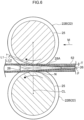
Fig. 10 is a sectional diagram (a sectional diagram corresponding toFig. 2 ) showing a variant example of the mandrel shown inFig. 2 . -
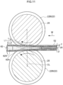
Fig. 11 is a sectional diagram (a sectional diagram corresponding toFig. 4 ) showing the variant example of the mandrel shown inFig. 10 . - Below, a multiple-winding pipe forming device and multiple-winding pipe forming method according to an exemplary embodiment relating to the present disclosure are described with reference to the drawings. An arrow M that is shown where appropriate in the drawings is a feeding direction of a
metal sheet 52. - First, a multiple-winding
pipe 50 that is fabricated using a multiple-winding pipe forming device (below referred to where appropriate as "the forming device") 20 is described. Then, the formingdevice 20 is described, after which a forming method using the formingdevice 20 is described. -
Fig. 8 shows the multiple-windingpipe 50 according to the present exemplary embodiment. The multiple-windingpipe 50 is formed by themetal sheet 52 being wound in a roll shape and superposed surfaces of superposed portions of themetal sheet 52 being joined together. The multiple-windingpipe 50 according to the present exemplary embodiment is a two-winding pipe. The multiple-windingpipe 50 is used as, for example, a piping component of a vehicle (for example, brake piping). - As shown in
Fig. 9 , themetal sheet 52 that forms the multiple-windingpipe 50 is formed by coating acore member 54 with acoating member 56. Thecore member 54 is formed of a metal material, and thecoating member 56 is formed of a metal material with a lower melting point than thecore member 54. Themetal sheet 52 is machined into a belt shape; a length direction of themetal sheet 52 matches an axial direction (a direction along an axis) of the multiple-windingpipe 50 after the multiple-windingpipe 50 is formed. A clad steel sheet and a coated steel sheet can be mentioned as examples of themetal sheet 52. Iron, aluminium or the like may be employed as the metal material forming thecore member 54. Copper, an aluminium alloy or the like that is used as a common brazing material may be employed as the metal material forming thecoating member 56. In the present exemplary embodiment, two faces of thecore member 54 are coated with thecoating member 56, but structures are possible in which only one face of thecore member 54 is coated with thecoating member 56. In the present exemplary embodiment, after themetal sheet 52 is wound into the roll shape, superposed surfaces of superposed portions of themetal sheet 52 are joined by brazing to form the multiple-windingpipe 50. - Now, the forming
device 20 according to the present exemplary embodiment is described. - As shown in
Fig. 1 to Fig. 4 , the formingdevice 20 is an apparatus that curls themetal sheet 52 and winds themetal sheet 52 into a roll shape, forming a roll in a pipe shape with a predetermined inner diameter (roll forming). - The forming
device 20 is provided with plural pairs of formingrollers 22 and amandrel 24 that is fabricated of metal. The pairs of formingrollers 22 are arranged along the feeding direction of the metal sheet 52 (below shortened where appropriate to "the feeding direction"). Themandrel 24 is arranged along the feeding direction. - As shown in
Fig. 1 andFig. 3 , the plural pairs of the formingrollers 22 are disposed as plural pairs spaced apart along the feeding direction, with each pair of the formingrollers 22 opposing one another so as to sandwich themetal sheet 52, which is an object of forming. Themetal sheet 52 is curled and wound into the roll shape by these formingrollers 22. - Plural pairs of assisting
rollers 23 that assist in the curling of themetal sheet 52 are disposed between adjacent pairs of the formingrollers 22 along the feeding direction. - Of the plural pairs of forming
rollers 22, a pair of formingrollers 22A is disposed furthest upstream in the feeding direction. Themetal sheet 52 is wound on adrum 58. The formingrollers 22A function as feeding rollers that sandwich themetal sheet 52 from two sheet face sides thereof and feed themetal sheet 52 wound on thedrum 58 out in the feeding direction. - Of the plural pairs of forming
rollers 22, a pair of formingrollers 22B is disposed furthest downstream in the feeding direction. The formingrollers 22B function as pressure rollers that compress superposed portions of themetal sheet 52 wound in the roll shape between the formingrollers 22B and ataper portion 28A of themandrel 24, which is described below, and putsuperposed surfaces metal sheet 52 into contact without gaps. Acircumferential trench 25 is formed in each of the pair of formingrollers 22B. Themetal sheet 52 wound in the roll shape is inserted into eachcircumferential trench 25. Thecircumferential trench 25 is formed continuously in the circumferential direction over the whole circumference of the formingroller 22B. - Of the plural pairs of forming
rollers 22, plural pairs of formingrollers 22C are disposed between the pair of formingrollers 22A and the pair of formingrollers 22B. The formingrollers 22C function as curl-forming rollers that, from an upstream side toward a downstream side in the feeding direction, progressively curl themetal sheet 52 to wind themetal sheet 52 into the roll shape. - As shown in
Fig. 1 andFig. 3 , themandrel 24 includes ashaft 26 and a workingportion 28. - The
shaft 26 extends along the feeding direction. More specifically, theshaft 26 extends from a space between the pair of formingrollers 22A and one pair of the formingrollers 22C to just before a nipping portion N of the pair of formingrollers 22B. According to this structure, a region of the shaft 26 (a region at the downstream side thereof in the feeding direction) is disposed inside themetal sheet 52 wound in the roll shape. Theshaft 26 is formed of a metal material (for example, iron). The meaning of the term "nipping portion N" as used herein is intended to include a position at which themetal sheet 52 wound in the roll shape is sandwiched by the pair of formingrollers 22B disposed furthest downstream in the feeding direction. - One
end 26A of theshaft 26 is disposed at the upstream side thereof in the feeding direction. A disc-shapedspool portion 27 is formed at the oneend 26A side of theshaft 26 and protrudes to diametric direction outer sides from theshaft 26. Thespool portion 27 is employed such that theshaft 26 is retained by aretention portion 32 of a movingapparatus 30, which is described below. - Another
end 26B of theshaft 26 is disposed at the downstream side thereof in the feeding direction, which is an opposite side of theshaft 26 from a side thereof at which the oneend 26A is disposed. The workingportion 28 is provided at the anotherend 26B side of the shaft 26 (in the present exemplary embodiment, at the anotherend 26B). The workingportion 28 includes thetaper portion 28A, which increases in diameter from upstream to downstream in the feeding direction. The workingportion 28 is formed of a metal material (for example, iron) and is joined to the anotherend 26B of theshaft 26 by welding. - A position of the
mandrel 24 along the feeding direction is controlled by the movingapparatus 30, which is described below, such that thetaper portion 28A of the workingportion 28 is disposed at the nipping portion N of the pair of formingrollers 22B. - As shown in
Fig. 1 andFig. 3 , the formingdevice 20 is further provided with the movingapparatus 30 that moves themandrel 24 along the feeding direction. - The moving
apparatus 30 includes theretention portion 32, adrive source 34, asensor 36 and acontrol section 38. - The
retention portion 32 is coupled to ahousing 31 that retains the oneend 26A side of theshaft 26 and is structured to be movable by sliding along the feeding direction. Theretention portion 32 supports the oneend 26A side of theshaft 26 and moves together with thehousing 31 along the feeding direction. An engaging portion, which is not shown in the drawings, is provided at theretention portion 32. The engaging portion engages with thespool portion 27 of theshaft 26. Thus, themandrel 24 moves with movement of theretention portion 32. - The
drive source 34 is coupled to thehousing 31 via a ball-and-screw mechanism (not shown in the drawings) for sliding thehousing 31. Thedrive source 34 supplies driving force to move both thehousing 31 and theretention portion 32 along the feeding direction. Thedrive source 34 that is employed may be, for example, an electric motor (a servo motor). Thedrive source 34 is controlled by thecontrol section 38. - The
sensor 36 is disposed in the housing. Thesensor 36 detects tension acting on theshaft 26, via theretention portion 32. Information detected by thesensor 36 is sent to thecontrol section 38. - The
control section 38 controls output power (driving force) of thedrive source 34, in accordance with information relating to the tension detected by thesensor 36, so as to adjust the position of theretention portion 32 in the feeding direction. Thus, thecontrol section 38 may adjust a position of thetaper portion 28A of the workingportion 28 in the feeding direction. - Now, the multiple-winding pipe forming method using the forming
device 20 according to the present exemplary embodiment is described. - Before formation of a multiple-winding pipe begins, a size (wall thickness, internal diameter and so forth) of the multiple-winding pipe to be formed is entered into a memory section, which is not shown in the drawings, of the
control section 38 through an operation section, which is not shown in the drawings. On the basis of this size information, thecontrol section 38 controls thedrive source 34 and disposes thetaper portion 28A of the workingportion 28 at an optimum position of the nipping portion N of the pair of formingrollers 22B (an optimum position in the feeding direction). This optimum position is specified in advance on the basis of the size information by calculation or the like. More specifically, thecontrol section 38 controls thedrive source 34 such that a distance L2 between each formingroller 22B and thetaper portion 28A (seeFig. 2 ) is the same as a thickness T of a peripheral wall portion of the multiple-windingpipe 50, which is entered in the size information. Thus, thetaper portion 28A is disposed at the optimum position of the nipping portion N of the pair of formingrollers 22B. - Distances between the pair of forming
rollers 22A, the pair of formingrollers 22B, the plural pairs of formingrollers 22C and the plural pairs of assistingrollers 23 are also altered on the basis of the entered information. For example, a distance L1 along a center line CL between floor surfaces of thecircumferential trenches 25 of the pair of formingrollers 22B is altered. - Then, the
metal sheet 52 is pulled out from thedrum 58, and a leading end portion of themetal sheet 52 is disposed between and nipped by the pair of formingrollers 22A. The pair of formingrollers 22A turn in synchrony and feed out the nippedmetal sheet 52 from upstream to downstream in the feeding direction. Themetal sheet 52 fed out from the pair of formingrollers 22A is curled by the plural pairs of formingrollers 22C and the plural pairs of assistingrollers 23 and is wound into the roll shape. Themetal sheet 52 is wound into the roll shape so as to encircle theshaft 26 of themandrel 24. When themetal sheet 52 is passing through the plural pairs of formingrollers 22C, themetal sheet 52 is wound into the roll shape in a state in which gaps are formed between superposed portions of themetal sheet 52. - Then, at the nipping portion N of the pair of forming
rollers 22B, the superposed portions of themetal sheet 52 wound in the roll shape are compressed by the pair of formingrollers 22B and thetaper portion 28A of the workingportion 28. More specifically, in the formingdevice 20 as shown inFig. 4 , a roll inner side portion of themetal sheet 52 wound in the roll shape increases in diameter while riding over thetaper portion 28A of the workingportion 28. As shown inFig. 7 , in a state in which thesuperposed surfaces metal sheet 52 wound in the roll shape touch without gaps (that is, a tightly contacted state), the superposed portions of themetal sheet 52 wound in the roll shape are compressed from inside and outside the roll by the pair of formingrollers 22B and thetaper portion 28A of the workingportion 28. After the superposed portions are compressed but before the superposed portions are joined, as shown inFig. 4 andFig. 5 , the diameter of themetal sheet 52 wound in the roll shape increases after the compression while passing beyond a maximum diameter portion of thetaper portion 28A. - When there is inconsistency in the thickness of the
metal sheet 52 and, as illustrated inFig. 5 , the thickness T of themetal sheet 52 is greater than a standard sheet thickness (in the present exemplary embodiment, half of the entered wall thickness), frictional forces that are produced when the roll inner side portion of themetal sheet 52 wound in the roll shape rides over thetaper portion 28A of the workingportion 28 increase. Thus, a tension F acting on theshaft 26 of which the oneend 26A side is retained increases. When the tension F acting on theshaft 26 is greater, axial direction elongation (resilient elongation) of theshaft 26 fabricated of metal is greater, and the position of thetaper portion 28A shifts downstream in the feeding direction relative to when the thickness of themetal sheet 52 is the standard sheet thickness (that is, relative to when thetaper portion 28A is disposed at the optimum position of the nipping portion N mentioned above). When the position of thetaper portion 28A shifts downstream in this manner, the distance L2 between each formingroller 22B and thetaper portion 28A increases. As a result, an increase in pressure forces acting on the superposed portions of themetal sheet 52 wound in the roll shape between the pair of formingrollers 22B and thetaper portion 28A is suppressed. - Alternatively, as illustrated in
Fig. 6 , when the thickness T of themetal sheet 52 is smaller than the standard sheet thickness, the frictional forces that are produced when the roll inner side portion of themetal sheet 52 wound in the roll shape rides over thetaper portion 28A of the workingportion 28 decrease. Thus, the tension F acting on theshaft 26 of which the oneend 26A side is retained decreases. When the tension F acting on theshaft 26 is smaller, axial direction elongation (resilient elongation) of theshaft 26 fabricated of metal is smaller than when the thickness of themetal sheet 52 is the standard sheet thickness, and the position of thetaper portion 28A shifts upstream in the feeding direction. When the position of thetaper portion 28A shifts upstream in this manner, the distance L2 between each formingroller 22B and thetaper portion 28A decreases. As a result, a decrease in the pressure forces acting on the superposed portions of themetal sheet 52 wound in the roll shape between the pair of formingrollers 22B and thetaper portion 28A is suppressed. - In the forming
device 20 as described above, even when the thickness T of themetal sheet 52 is inconsistent, pressure forces on the superposed portions of themetal sheet 52 wound in the roll shape may be made more uniform. - The meaning of the term "inconsistency in the thickness of the metal sheet" as used herein is intended to include inconsistencies in thickness caused by fabrication errors, inconsistencies in thickness when a metal sheet that is used is specified to change in thickness along the length direction thereof, and so forth.
- In the present exemplary embodiment, the moving
apparatus 30 is employed. The tension F acting on theshaft 26 is detected by thesensor 36, thedrive source 34 is controlled by thecontrol section 38 in accordance with the tension F detected by thesensor 36, and the position in the feeding direction of theretention portion 32 that supports theshaft 26 is adjusted. More specifically, when thetaper portion 28A may not be disposed at the optimum position of the nipping portion N of the pair of formingrollers 22B by resilient elongation of theshaft 26 alone, thetaper portion 28A is disposed at the optimum position of the nipping portion N of the formingrollers 22B by the movingapparatus 30, taking account of the resilient elongation of theshaft 26. Therefore, in addition to the effects described above caused by resilient elongation of theshaft 26 fabricated of metal, pressure forces on the superposed portions of the metal sheet wound in the roll shape may be made even more uniform. - The
metal sheet 52 wound in the roll shape passes through the pair of formingrollers 22B and is heated in a heating step of a subsequent process. As a result of this heating, the superposed portions of themetal sheet 52 wound in the roll shape are joined by brazing. Thus, the multiple-windingpipe 50 is fabricated. Because the multiple-windingpipe 50 that is fabricated in this manner has been heated in a state in which thesuperposed surfaces metal sheet 52 wound in the roll shape are touching without gaps (that is, the tightly contacted state), the formation of voids (gaps) between thesuperposed surfaces - Now, operational effects of the multiple-winding
pipe 20 according to the present exemplary embodiment are described. - In the forming
device 20 as described above, pressure forces on the superposed portions of themetal sheet 52 wound in the roll shape may be made more uniform even when the thickness of themetal sheet 52 is inconsistent. - In the forming
device 20, because thetaper portion 28A is disposed at the optimum position of the nipping portion N of the pair of formingrollers 22B, one type of themandrel 24 may be applied to metal sheets of plural sizes (sheet thicknesses). Therefore, a number of types of themandrel 24 may be reduced. Hence, because the number of types of themandrel 24 is reduced, the labor of setting a different mandrel in the forming device for each size of metal sheet may be reduced. - In the forming
device 20, because the movingapparatus 30 is also provided, positions in the feeding direction of the pairs of formingrollers 22B and thetaper portion 28A of the workingportion 28 may be adjusted automatically prior to the forming of themetal sheet 52. Thus, thetaper portion 28A may be disposed at the optimum position of the nipping portion N of the pair of formingrollers 22B. - In the forming
device 20 as described above, thetaper portion 28A is disposed by the movingapparatus 30 at the optimum position of the nipping portion N of the pair of formingrollers 22B taking account of resilient elongation of theshaft 26. Therefore, in addition to the effects described above caused by resilient elongation of theshaft 26 fabricated of metal, pressure forces on the superposed portions of themetal sheet 52 wound in the roll shape may be made even more uniform. - In the forming
device 20 according to the exemplary embodiment described above, the workingportion 28 of themandrel 24 includes thetaper portion 28A, but the present disclosure is not limited by this structure. For example, as with amandrel 60 shown inFig. 10 andFig. 11 , a workingportion 62 may include acircular rod portion 62B that protrudes from an end of ataper portion 62A and is equal in diameter to the end of thetaper portion 62A. Thecircular rod portion 62B protrudes to an opposite side of the workingportion 62 from a side thereof at which theshaft 26 is disposed. In this structure, compared to, for example, a structure in which thecircular rod portion 62B is not provided and a terminal end of a taper portion has sharp angles, pressure forces acting on the end of thetaper portion 62A are dispersed and abrasion of themandrel 24 associated with the working of themetal sheet 52 is suppressed. - In the exemplary embodiment described above, the forming
device 20 includes the movingapparatus 30, but the present disclosure is not limited by this structure. The formingdevice 20 need not include the movingapparatus 30, in which case thetaper portion 28A is disposed at the optimum position of the nipping portion N only by the effects of resilient elongation of theshaft 26. - In the exemplary embodiment described above, the
taper portion 28A of the workingportion 28 is disposed at the nipping portion N of the pair of formingrollers 22B that are disposed furthest downstream in the feeding direction, but the present disclosure is not limited by this structure. For example, structures are possible in which thetaper portion 28A of the workingportion 28 is disposed at a nipping portion N of a pair of the formingrollers 22C that is disposed at the downstream side in the feeding direction and is the first pair upstream from the pair of formingrollers 22B (i.e., the pair of formingrollers 22C that is second furthest downstream). In this structure, themetal sheet 52 wound in the roll shape may be compressed at the pair of formingrollers 22C that is second furthest downstream, and fine adjustments of pipe diameter may be implemented at the pair of formingrollers 22B that is furthest downstream. - In the foregoing, an exemplary embodiment of the present disclosure has been illustrated and the exemplary embodiment has been described. However, this embodiment is an example; numerous modifications may be embodied within a scope not departing from the scope of the appended claims.
Claims (3)
- A multiple-winding pipe forming device (20) for forming a wound pipe, the multiple-winding pipe forming device comprising:a plurality of pairs of forming rollers (22) arranged along a feeding direction of a metal sheet (52) that is an object of forming, each pair of forming rollers (22) opposing one another so as to sandwich, in use, the metal sheet (52), and the plurality of pairs of forming rollers (22) being configured to curl the metal sheet (52) and to wind the metal sheet (22) into a roll shape; anda mandrel (24) fabricated of metal, the mandrel (24) including:a shaft (26) that extends in the feeding direction and is disposed, in use, inside the metal sheet (52) wound in the roll shape, one end (26A) side of the shaft (26) being retained, which one end side is disposed upstream in the feeding direction, anda working portion (28, 62) provided at an opposite end (26B) side of the shaft (26) from a side thereof at which the one end (26A) side is disposed, the working portion (28, 62) including a taper portion (28A, 62A) that increases in diameter from upstream to downstream in the feeding direction,wherein the taper portion (28A, 62A) of the working portion (28, 62) is disposed, in use, at a position at which the metal sheet (52) wound in the roll shape is sandwiched by, of the plurality of pairs of forming rollers (22), a pair of the forming rollers (22B) that is disposed at a downstream side in the feeding direction,characterized in thatthe multiple-winding pipe forming device further comprises a moving apparatus (30) that moves the mandrel (24) along the feeding direction, the moving apparatus (30) including:a retention portion (32) that retains the one end side of the shaft (26) and is movable to an upstream side and the downstream side in the feeding direction,a drive source (34) that moves the retention portion,a sensor (36) that, via the retention portion (32), detects tension acting on the shaft (26),a control section (38) that, in accordance with a tension detected by the sensor (36), controls the drive source (34) and adjusts a position of the retention portion (32) along the feeding direction;a position of the mandrel (24) along the feeding direction is controlled by the moving apparatus (30) such that the taper portion (28A, 62A) of the working portion (28) is disposed at the nipping portion (N) of the pair of forming rollers (22B).
- The multiple-winding pipe forming device (20) according to claim 1, wherein the working portion (62) includes a circular rod portion (62B) protruding from an end of the taper portion (62) to an opposite side of the taper portion (62A) from a side thereof at which the shaft (26) is disposed, the circular rod portion (62B) being equal in diameter to the end of the taper portion (62A).
- A multiple-winding pipe forming method using the multiple-winding pipe forming device (20) according to any one of claims 1 to 2, the multiple-winding pipe forming method comprising:curling the metal sheet (52) and winding the metal sheet (52) into the roll shape; andcompressing superposed portions of the metal sheet (52) wound in the roll shape between the taper portion (28A, 62A) of the working portion (28, 62) and the pair of forming rollers (22) that is disposed at the downstream side in the feeding direction of the metal sheet (52).
Applications Claiming Priority (2)
| Application Number | Priority Date | Filing Date | Title |
|---|---|---|---|
| JP2018140612A JP6913657B2 (en) | 2018-07-26 | 2018-07-26 | Multi-winding tube molding device and multi-winding tube molding method |
| PCT/JP2019/018006 WO2020021809A1 (en) | 2018-07-26 | 2019-04-26 | Molding device for multi-wound tube and molding method for multi-wound tube |
Publications (3)
| Publication Number | Publication Date |
|---|---|
| EP3827910A1 EP3827910A1 (en) | 2021-06-02 |
| EP3827910A4 EP3827910A4 (en) | 2022-04-27 |
| EP3827910B1 true EP3827910B1 (en) | 2024-03-27 |
Family
ID=69180677
Family Applications (1)
| Application Number | Title | Priority Date | Filing Date |
|---|---|---|---|
| EP19841989.7A Active EP3827910B1 (en) | 2018-07-26 | 2019-04-26 | Molding device for multi-wound tube and molding method for multi-wound tube |
Country Status (5)
| Country | Link |
|---|---|
| US (1) | US20210252576A1 (en) |
| EP (1) | EP3827910B1 (en) |
| JP (1) | JP6913657B2 (en) |
| CN (1) | CN112512712B (en) |
| WO (1) | WO2020021809A1 (en) |
Families Citing this family (2)
| Publication number | Priority date | Publication date | Assignee | Title |
|---|---|---|---|---|
| CN113245756B (en) * | 2021-05-27 | 2022-04-15 | 燕山大学 | Double-layer composite pipe straight seam welding heating device and process thereof |
| KR102907609B1 (en) * | 2023-01-27 | 2026-01-05 | 주식회사 성우하이텍 | Device for manufacturing closed sectional member |
Family Cites Families (17)
| Publication number | Priority date | Publication date | Assignee | Title |
|---|---|---|---|---|
| US3650138A (en) * | 1968-09-28 | 1972-03-21 | Giuseppe Persico | Multiple tube-rolling pilger mills |
| GB1565436A (en) * | 1977-10-10 | 1980-04-23 | Gni I Pi Splav I Obrabot Tsvet | Pilger rolling of tubes |
| FR2550108B1 (en) * | 1983-08-01 | 1986-06-27 | Vallourec | PROCESS FOR COLD ROLLING OF TUBES USING A PILGRIM STEEL ROLLING MACHINE AND ROLLING MACHINE FOR IMPLEMENTING SAME |
| US4866968A (en) * | 1987-06-17 | 1989-09-19 | Westinghouse Electric Corp. | High strength cemented carbide dies and mandrels for a pilgering machine |
| DE4106178C1 (en) * | 1991-02-27 | 1992-06-17 | Erhard Dipl.-Ing. 5608 Radevormwald De Hentzschel | |
| CN2127045Y (en) * | 1992-02-18 | 1993-02-17 | 符颖士 | Two-layer soldering pipe forming device |
| DE4333036A1 (en) * | 1993-09-30 | 1995-04-06 | Froh Roehren | Device for producing brazed multilayer metal pipes |
| JPH08215743A (en) * | 1995-02-15 | 1996-08-27 | Usui Internatl Ind Co Ltd | Multiple winding metallic tube and its production and apparatus therefor |
| FR2759483B1 (en) * | 1997-02-12 | 1999-04-30 | Zircotube | METHOD OF MANUFACTURING A TUBE-GUIDE OF A FUEL ASSEMBLY OF A NUCLEAR REACTOR, MANDRE FOR FORGING A TUBE-GUIDE AND TUBE-GUIDE OBTAINED |
| JPH11342418A (en) * | 1998-05-28 | 1999-12-14 | Usui Internatl Ind Co Ltd | Multiplex wind tube forming device |
| WO2004105975A1 (en) * | 2003-03-24 | 2004-12-09 | Yamaha Motor Co., Ltd. | Method and device for bending material tube |
| US7765841B2 (en) * | 2006-02-16 | 2010-08-03 | Oes, Inc. | Quality analysis of tube bending processes including mandrel fault detection |
| CN103341521A (en) * | 2013-06-19 | 2013-10-09 | 武汉理工大学 | Method for optimization of pipe integrated numerical control machining process |
| BR102013021663B1 (en) * | 2013-08-23 | 2020-08-25 | Vallourec Soluções Tubulares Do Brasil S.A. | process for the production of expansion coated tube and coated tube produced by this process |
| JP6327868B2 (en) * | 2014-01-29 | 2018-05-23 | 三桜工業株式会社 | Manufacturing method of heat exchanger |
| DE102017102139B3 (en) * | 2017-02-03 | 2018-03-29 | Benteler Automobiltechnik Gmbh | Forming tool for producing a hollow component and method for producing a Umformbauteils |
| JP6878047B2 (en) | 2017-02-28 | 2021-05-26 | 住友重機械工業株式会社 | Injection molding machine and injection molding method |
-
2018
- 2018-07-26 JP JP2018140612A patent/JP6913657B2/en active Active
-
2019
- 2019-04-26 WO PCT/JP2019/018006 patent/WO2020021809A1/en not_active Ceased
- 2019-04-26 US US17/262,785 patent/US20210252576A1/en not_active Abandoned
- 2019-04-26 CN CN201980049635.1A patent/CN112512712B/en active Active
- 2019-04-26 EP EP19841989.7A patent/EP3827910B1/en active Active
Also Published As
| Publication number | Publication date |
|---|---|
| WO2020021809A1 (en) | 2020-01-30 |
| EP3827910A4 (en) | 2022-04-27 |
| US20210252576A1 (en) | 2021-08-19 |
| JP2020015077A (en) | 2020-01-30 |
| EP3827910A1 (en) | 2021-06-02 |
| CN112512712A (en) | 2021-03-16 |
| JP6913657B2 (en) | 2021-08-04 |
| CN112512712B (en) | 2023-05-09 |
Similar Documents
| Publication | Publication Date | Title |
|---|---|---|
| JP2013069637A (en) | Band electrode manufacturing apparatus and method of manufacturing the same | |
| EP3827910A1 (en) | Molding device for multi-wound tube and molding method for multi-wound tube | |
| US8516682B2 (en) | Manufacturing method of a stator core of rotating electrical machine | |
| WO1999050002A1 (en) | Method and device for taking up metal foil | |
| JP5751534B2 (en) | Method for manufacturing stator core of rotating electric machine | |
| CN108290191B (en) | Coil feeding device and coil feeding method | |
| EP2729266B1 (en) | Method of forming a tubular member | |
| EP1574466B1 (en) | Stackable winding core and method of making same | |
| JP2013215772A (en) | Method for manufacturing thickened spiral blade, steel pipe pile with thickened spiral blade using the same, and apparatus for manufacturing the thickened spiral blade | |
| US20180281035A1 (en) | Rolling bending method and rolling bending apparatus | |
| CN115087786B (en) | Tubular structure | |
| US6588245B2 (en) | Roll gap control for coiler | |
| CN113260501B (en) | Method and apparatus for coating bead core | |
| JP2010046675A (en) | Pipe bending device and pipe bending method | |
| JP7077755B2 (en) | Rolling bending equipment | |
| JP3241660B2 (en) | Control method of winding pinch roll | |
| JP2020015077A5 (en) | ||
| JP4505071B2 (en) | Steel strip joining method | |
| GB2057393A (en) | Strip feed | |
| JP7727001B2 (en) | Rolling device control device, rolling equipment, and rolling device control method | |
| JP7371450B2 (en) | Winding forming method and winding forming device | |
| JP2013091194A (en) | Pressing roller for tire molding, and method for pressing rubber material for the tire molding | |
| JP3900990B2 (en) | Uneven wall pipe manufacturing method | |
| CN104936715B (en) | Ribbon winding device | |
| JPH08281328A (en) | Tube winding device and winding method |
Legal Events
| Date | Code | Title | Description |
|---|---|---|---|
| STAA | Information on the status of an ep patent application or granted ep patent |
Free format text: STATUS: THE INTERNATIONAL PUBLICATION HAS BEEN MADE |
|
| PUAI | Public reference made under article 153(3) epc to a published international application that has entered the european phase |
Free format text: ORIGINAL CODE: 0009012 |
|
| STAA | Information on the status of an ep patent application or granted ep patent |
Free format text: STATUS: REQUEST FOR EXAMINATION WAS MADE |
|
| 17P | Request for examination filed |
Effective date: 20210219 |
|
| AK | Designated contracting states |
Kind code of ref document: A1 Designated state(s): AL AT BE BG CH CY CZ DE DK EE ES FI FR GB GR HR HU IE IS IT LI LT LU LV MC MK MT NL NO PL PT RO RS SE SI SK SM TR |
|
| DAV | Request for validation of the european patent (deleted) | ||
| DAX | Request for extension of the european patent (deleted) | ||
| A4 | Supplementary search report drawn up and despatched |
Effective date: 20220325 |
|
| RIC1 | Information provided on ipc code assigned before grant |
Ipc: B21D 5/12 20060101ALI20220321BHEP Ipc: B21C 37/08 20060101ALI20220321BHEP Ipc: B21C 37/06 20060101AFI20220321BHEP |
|
| STAA | Information on the status of an ep patent application or granted ep patent |
Free format text: STATUS: EXAMINATION IS IN PROGRESS |
|
| 17Q | First examination report despatched |
Effective date: 20230313 |
|
| GRAP | Despatch of communication of intention to grant a patent |
Free format text: ORIGINAL CODE: EPIDOSNIGR1 |
|
| STAA | Information on the status of an ep patent application or granted ep patent |
Free format text: STATUS: GRANT OF PATENT IS INTENDED |
|
| INTG | Intention to grant announced |
Effective date: 20231120 |
|
| GRAS | Grant fee paid |
Free format text: ORIGINAL CODE: EPIDOSNIGR3 |
|
| GRAA | (expected) grant |
Free format text: ORIGINAL CODE: 0009210 |
|
| STAA | Information on the status of an ep patent application or granted ep patent |
Free format text: STATUS: THE PATENT HAS BEEN GRANTED |
|
| AK | Designated contracting states |
Kind code of ref document: B1 Designated state(s): AL AT BE BG CH CY CZ DE DK EE ES FI FR GB GR HR HU IE IS IT LI LT LU LV MC MK MT NL NO PL PT RO RS SE SI SK SM TR |
|
| REG | Reference to a national code |
Ref country code: GB Ref legal event code: FG4D |
|
| REG | Reference to a national code |
Ref country code: CH Ref legal event code: EP |
|
| REG | Reference to a national code |
Ref country code: DE Ref legal event code: R096 Ref document number: 602019049167 Country of ref document: DE |
|
| REG | Reference to a national code |
Ref country code: IE Ref legal event code: FG4D |
|
| PG25 | Lapsed in a contracting state [announced via postgrant information from national office to epo] |
Ref country code: LT Free format text: LAPSE BECAUSE OF FAILURE TO SUBMIT A TRANSLATION OF THE DESCRIPTION OR TO PAY THE FEE WITHIN THE PRESCRIBED TIME-LIMIT Effective date: 20240327 |
|
| REG | Reference to a national code |
Ref country code: LT Ref legal event code: MG9D |
|
| PG25 | Lapsed in a contracting state [announced via postgrant information from national office to epo] |
Ref country code: GR Free format text: LAPSE BECAUSE OF FAILURE TO SUBMIT A TRANSLATION OF THE DESCRIPTION OR TO PAY THE FEE WITHIN THE PRESCRIBED TIME-LIMIT Effective date: 20240628 |
|
| PG25 | Lapsed in a contracting state [announced via postgrant information from national office to epo] |
Ref country code: RS Free format text: LAPSE BECAUSE OF FAILURE TO SUBMIT A TRANSLATION OF THE DESCRIPTION OR TO PAY THE FEE WITHIN THE PRESCRIBED TIME-LIMIT Effective date: 20240627 Ref country code: HR Free format text: LAPSE BECAUSE OF FAILURE TO SUBMIT A TRANSLATION OF THE DESCRIPTION OR TO PAY THE FEE WITHIN THE PRESCRIBED TIME-LIMIT Effective date: 20240327 |
|
| PG25 | Lapsed in a contracting state [announced via postgrant information from national office to epo] |
Ref country code: RS Free format text: LAPSE BECAUSE OF FAILURE TO SUBMIT A TRANSLATION OF THE DESCRIPTION OR TO PAY THE FEE WITHIN THE PRESCRIBED TIME-LIMIT Effective date: 20240627 Ref country code: NO Free format text: LAPSE BECAUSE OF FAILURE TO SUBMIT A TRANSLATION OF THE DESCRIPTION OR TO PAY THE FEE WITHIN THE PRESCRIBED TIME-LIMIT Effective date: 20240627 Ref country code: LT Free format text: LAPSE BECAUSE OF FAILURE TO SUBMIT A TRANSLATION OF THE DESCRIPTION OR TO PAY THE FEE WITHIN THE PRESCRIBED TIME-LIMIT Effective date: 20240327 Ref country code: HR Free format text: LAPSE BECAUSE OF FAILURE TO SUBMIT A TRANSLATION OF THE DESCRIPTION OR TO PAY THE FEE WITHIN THE PRESCRIBED TIME-LIMIT Effective date: 20240327 Ref country code: GR Free format text: LAPSE BECAUSE OF FAILURE TO SUBMIT A TRANSLATION OF THE DESCRIPTION OR TO PAY THE FEE WITHIN THE PRESCRIBED TIME-LIMIT Effective date: 20240628 Ref country code: FI Free format text: LAPSE BECAUSE OF FAILURE TO SUBMIT A TRANSLATION OF THE DESCRIPTION OR TO PAY THE FEE WITHIN THE PRESCRIBED TIME-LIMIT Effective date: 20240327 Ref country code: BG Free format text: LAPSE BECAUSE OF FAILURE TO SUBMIT A TRANSLATION OF THE DESCRIPTION OR TO PAY THE FEE WITHIN THE PRESCRIBED TIME-LIMIT Effective date: 20240327 |
|
| REG | Reference to a national code |
Ref country code: NL Ref legal event code: MP Effective date: 20240327 |
|
| PG25 | Lapsed in a contracting state [announced via postgrant information from national office to epo] |
Ref country code: SE Free format text: LAPSE BECAUSE OF FAILURE TO SUBMIT A TRANSLATION OF THE DESCRIPTION OR TO PAY THE FEE WITHIN THE PRESCRIBED TIME-LIMIT Effective date: 20240327 Ref country code: LV Free format text: LAPSE BECAUSE OF FAILURE TO SUBMIT A TRANSLATION OF THE DESCRIPTION OR TO PAY THE FEE WITHIN THE PRESCRIBED TIME-LIMIT Effective date: 20240327 |
|
| PG25 | Lapsed in a contracting state [announced via postgrant information from national office to epo] |
Ref country code: NL Free format text: LAPSE BECAUSE OF FAILURE TO SUBMIT A TRANSLATION OF THE DESCRIPTION OR TO PAY THE FEE WITHIN THE PRESCRIBED TIME-LIMIT Effective date: 20240327 |
|
| REG | Reference to a national code |
Ref country code: AT Ref legal event code: MK05 Ref document number: 1669432 Country of ref document: AT Kind code of ref document: T Effective date: 20240327 |
|
| PG25 | Lapsed in a contracting state [announced via postgrant information from national office to epo] |
Ref country code: NL Free format text: LAPSE BECAUSE OF FAILURE TO SUBMIT A TRANSLATION OF THE DESCRIPTION OR TO PAY THE FEE WITHIN THE PRESCRIBED TIME-LIMIT Effective date: 20240327 |
|
| PG25 | Lapsed in a contracting state [announced via postgrant information from national office to epo] |
Ref country code: IS Free format text: LAPSE BECAUSE OF FAILURE TO SUBMIT A TRANSLATION OF THE DESCRIPTION OR TO PAY THE FEE WITHIN THE PRESCRIBED TIME-LIMIT Effective date: 20240727 |
|
| PG25 | Lapsed in a contracting state [announced via postgrant information from national office to epo] |
Ref country code: PT Free format text: LAPSE BECAUSE OF FAILURE TO SUBMIT A TRANSLATION OF THE DESCRIPTION OR TO PAY THE FEE WITHIN THE PRESCRIBED TIME-LIMIT Effective date: 20240729 Ref country code: SM Free format text: LAPSE BECAUSE OF FAILURE TO SUBMIT A TRANSLATION OF THE DESCRIPTION OR TO PAY THE FEE WITHIN THE PRESCRIBED TIME-LIMIT Effective date: 20240327 |
|
| PG25 | Lapsed in a contracting state [announced via postgrant information from national office to epo] |
Ref country code: ES Free format text: LAPSE BECAUSE OF FAILURE TO SUBMIT A TRANSLATION OF THE DESCRIPTION OR TO PAY THE FEE WITHIN THE PRESCRIBED TIME-LIMIT Effective date: 20240327 |
|
| PG25 | Lapsed in a contracting state [announced via postgrant information from national office to epo] |
Ref country code: EE Free format text: LAPSE BECAUSE OF FAILURE TO SUBMIT A TRANSLATION OF THE DESCRIPTION OR TO PAY THE FEE WITHIN THE PRESCRIBED TIME-LIMIT Effective date: 20240327 Ref country code: CZ Free format text: LAPSE BECAUSE OF FAILURE TO SUBMIT A TRANSLATION OF THE DESCRIPTION OR TO PAY THE FEE WITHIN THE PRESCRIBED TIME-LIMIT Effective date: 20240327 |
|
| PG25 | Lapsed in a contracting state [announced via postgrant information from national office to epo] |
Ref country code: AT Free format text: LAPSE BECAUSE OF FAILURE TO SUBMIT A TRANSLATION OF THE DESCRIPTION OR TO PAY THE FEE WITHIN THE PRESCRIBED TIME-LIMIT Effective date: 20240327 |
|
| PG25 | Lapsed in a contracting state [announced via postgrant information from national office to epo] |
Ref country code: PL Free format text: LAPSE BECAUSE OF FAILURE TO SUBMIT A TRANSLATION OF THE DESCRIPTION OR TO PAY THE FEE WITHIN THE PRESCRIBED TIME-LIMIT Effective date: 20240327 |
|
| PG25 | Lapsed in a contracting state [announced via postgrant information from national office to epo] |
Ref country code: SK Free format text: LAPSE BECAUSE OF FAILURE TO SUBMIT A TRANSLATION OF THE DESCRIPTION OR TO PAY THE FEE WITHIN THE PRESCRIBED TIME-LIMIT Effective date: 20240327 |
|
| PG25 | Lapsed in a contracting state [announced via postgrant information from national office to epo] |
Ref country code: SM Free format text: LAPSE BECAUSE OF FAILURE TO SUBMIT A TRANSLATION OF THE DESCRIPTION OR TO PAY THE FEE WITHIN THE PRESCRIBED TIME-LIMIT Effective date: 20240327 Ref country code: SK Free format text: LAPSE BECAUSE OF FAILURE TO SUBMIT A TRANSLATION OF THE DESCRIPTION OR TO PAY THE FEE WITHIN THE PRESCRIBED TIME-LIMIT Effective date: 20240327 Ref country code: RO Free format text: LAPSE BECAUSE OF FAILURE TO SUBMIT A TRANSLATION OF THE DESCRIPTION OR TO PAY THE FEE WITHIN THE PRESCRIBED TIME-LIMIT Effective date: 20240327 Ref country code: PT Free format text: LAPSE BECAUSE OF FAILURE TO SUBMIT A TRANSLATION OF THE DESCRIPTION OR TO PAY THE FEE WITHIN THE PRESCRIBED TIME-LIMIT Effective date: 20240729 Ref country code: PL Free format text: LAPSE BECAUSE OF FAILURE TO SUBMIT A TRANSLATION OF THE DESCRIPTION OR TO PAY THE FEE WITHIN THE PRESCRIBED TIME-LIMIT Effective date: 20240327 Ref country code: IS Free format text: LAPSE BECAUSE OF FAILURE TO SUBMIT A TRANSLATION OF THE DESCRIPTION OR TO PAY THE FEE WITHIN THE PRESCRIBED TIME-LIMIT Effective date: 20240727 Ref country code: ES Free format text: LAPSE BECAUSE OF FAILURE TO SUBMIT A TRANSLATION OF THE DESCRIPTION OR TO PAY THE FEE WITHIN THE PRESCRIBED TIME-LIMIT Effective date: 20240327 Ref country code: EE Free format text: LAPSE BECAUSE OF FAILURE TO SUBMIT A TRANSLATION OF THE DESCRIPTION OR TO PAY THE FEE WITHIN THE PRESCRIBED TIME-LIMIT Effective date: 20240327 Ref country code: CZ Free format text: LAPSE BECAUSE OF FAILURE TO SUBMIT A TRANSLATION OF THE DESCRIPTION OR TO PAY THE FEE WITHIN THE PRESCRIBED TIME-LIMIT Effective date: 20240327 Ref country code: AT Free format text: LAPSE BECAUSE OF FAILURE TO SUBMIT A TRANSLATION OF THE DESCRIPTION OR TO PAY THE FEE WITHIN THE PRESCRIBED TIME-LIMIT Effective date: 20240327 |
|
| REG | Reference to a national code |
Ref country code: CH Ref legal event code: PL |
|
| PG25 | Lapsed in a contracting state [announced via postgrant information from national office to epo] |
Ref country code: IT Free format text: LAPSE BECAUSE OF FAILURE TO SUBMIT A TRANSLATION OF THE DESCRIPTION OR TO PAY THE FEE WITHIN THE PRESCRIBED TIME-LIMIT Effective date: 20240327 |
|
| PG25 | Lapsed in a contracting state [announced via postgrant information from national office to epo] |
Ref country code: LU Free format text: LAPSE BECAUSE OF NON-PAYMENT OF DUE FEES Effective date: 20240426 |
|
| REG | Reference to a national code |
Ref country code: BE Ref legal event code: MM Effective date: 20240430 |
|
| PG25 | Lapsed in a contracting state [announced via postgrant information from national office to epo] |
Ref country code: LU Free format text: LAPSE BECAUSE OF NON-PAYMENT OF DUE FEES Effective date: 20240426 Ref country code: IT Free format text: LAPSE BECAUSE OF FAILURE TO SUBMIT A TRANSLATION OF THE DESCRIPTION OR TO PAY THE FEE WITHIN THE PRESCRIBED TIME-LIMIT Effective date: 20240327 |
|
| REG | Reference to a national code |
Ref country code: DE Ref legal event code: R097 Ref document number: 602019049167 Country of ref document: DE |
|
| PG25 | Lapsed in a contracting state [announced via postgrant information from national office to epo] |
Ref country code: MC Free format text: LAPSE BECAUSE OF FAILURE TO SUBMIT A TRANSLATION OF THE DESCRIPTION OR TO PAY THE FEE WITHIN THE PRESCRIBED TIME-LIMIT Effective date: 20240327 |
|
| PG25 | Lapsed in a contracting state [announced via postgrant information from national office to epo] |
Ref country code: DK Free format text: LAPSE BECAUSE OF FAILURE TO SUBMIT A TRANSLATION OF THE DESCRIPTION OR TO PAY THE FEE WITHIN THE PRESCRIBED TIME-LIMIT Effective date: 20240327 |
|
| PG25 | Lapsed in a contracting state [announced via postgrant information from national office to epo] |
Ref country code: BE Free format text: LAPSE BECAUSE OF NON-PAYMENT OF DUE FEES Effective date: 20240430 |
|
| PG25 | Lapsed in a contracting state [announced via postgrant information from national office to epo] |
Ref country code: MC Free format text: LAPSE BECAUSE OF FAILURE TO SUBMIT A TRANSLATION OF THE DESCRIPTION OR TO PAY THE FEE WITHIN THE PRESCRIBED TIME-LIMIT Effective date: 20240327 Ref country code: DK Free format text: LAPSE BECAUSE OF FAILURE TO SUBMIT A TRANSLATION OF THE DESCRIPTION OR TO PAY THE FEE WITHIN THE PRESCRIBED TIME-LIMIT Effective date: 20240327 Ref country code: BE Free format text: LAPSE BECAUSE OF NON-PAYMENT OF DUE FEES Effective date: 20240430 Ref country code: CH Free format text: LAPSE BECAUSE OF NON-PAYMENT OF DUE FEES Effective date: 20240430 |
|
| PLBE | No opposition filed within time limit |
Free format text: ORIGINAL CODE: 0009261 |
|
| STAA | Information on the status of an ep patent application or granted ep patent |
Free format text: STATUS: NO OPPOSITION FILED WITHIN TIME LIMIT |
|
| GBPC | Gb: european patent ceased through non-payment of renewal fee |
Effective date: 20240627 |
|
| 26N | No opposition filed |
Effective date: 20250103 |
|
| PG25 | Lapsed in a contracting state [announced via postgrant information from national office to epo] |
Ref country code: IE Free format text: LAPSE BECAUSE OF NON-PAYMENT OF DUE FEES Effective date: 20240426 |
|
| PG25 | Lapsed in a contracting state [announced via postgrant information from national office to epo] |
Ref country code: SI Free format text: LAPSE BECAUSE OF FAILURE TO SUBMIT A TRANSLATION OF THE DESCRIPTION OR TO PAY THE FEE WITHIN THE PRESCRIBED TIME-LIMIT Effective date: 20240327 |
|
| PG25 | Lapsed in a contracting state [announced via postgrant information from national office to epo] |
Ref country code: FR Free format text: LAPSE BECAUSE OF NON-PAYMENT OF DUE FEES Effective date: 20240527 |
|
| PG25 | Lapsed in a contracting state [announced via postgrant information from national office to epo] |
Ref country code: GB Free format text: LAPSE BECAUSE OF NON-PAYMENT OF DUE FEES Effective date: 20240627 |
|
| PGFP | Annual fee paid to national office [announced via postgrant information from national office to epo] |
Ref country code: DE Payment date: 20250305 Year of fee payment: 7 |
|
| PGFP | Annual fee paid to national office [announced via postgrant information from national office to epo] |
Ref country code: TR Payment date: 20250411 Year of fee payment: 7 |
|
| PG25 | Lapsed in a contracting state [announced via postgrant information from national office to epo] |
Ref country code: CY Free format text: LAPSE BECAUSE OF FAILURE TO SUBMIT A TRANSLATION OF THE DESCRIPTION OR TO PAY THE FEE WITHIN THE PRESCRIBED TIME-LIMIT; INVALID AB INITIO Effective date: 20190426 |
|
| PG25 | Lapsed in a contracting state [announced via postgrant information from national office to epo] |
Ref country code: HU Free format text: LAPSE BECAUSE OF FAILURE TO SUBMIT A TRANSLATION OF THE DESCRIPTION OR TO PAY THE FEE WITHIN THE PRESCRIBED TIME-LIMIT; INVALID AB INITIO Effective date: 20190426 |