EP3827909A1 - Tension system optimization method for suppressing vibration of cold tandem rolling mill - Google Patents
Tension system optimization method for suppressing vibration of cold tandem rolling mill Download PDFInfo
- Publication number
- EP3827909A1 EP3827909A1 EP19842345.1A EP19842345A EP3827909A1 EP 3827909 A1 EP3827909 A1 EP 3827909A1 EP 19842345 A EP19842345 A EP 19842345A EP 3827909 A1 EP3827909 A1 EP 3827909A1
- Authority
- EP
- European Patent Office
- Prior art keywords
- machine frame
- strip
- vibration
- rolling mill
- work roll
- Prior art date
- Legal status (The legal status is an assumption and is not a legal conclusion. Google has not performed a legal analysis and makes no representation as to the accuracy of the status listed.)
- Granted
Links
Images
Classifications
-
- B—PERFORMING OPERATIONS; TRANSPORTING
- B21—MECHANICAL METAL-WORKING WITHOUT ESSENTIALLY REMOVING MATERIAL; PUNCHING METAL
- B21B—ROLLING OF METAL
- B21B37/00—Control devices or methods specially adapted for metal-rolling mills or the work produced thereby
- B21B37/007—Control for preventing or reducing vibration, chatter or chatter marks
-
- B—PERFORMING OPERATIONS; TRANSPORTING
- B21—MECHANICAL METAL-WORKING WITHOUT ESSENTIALLY REMOVING MATERIAL; PUNCHING METAL
- B21B—ROLLING OF METAL
- B21B37/00—Control devices or methods specially adapted for metal-rolling mills or the work produced thereby
- B21B37/48—Tension control; Compression control
Definitions
- the present invention relates to the technical field of metallurgical steel rolling, and more particularly relates to a tension system optimization method for suppressing vibration of a cold tandem rolling mill.
- Patent 201410026171.1 provides a tension system optimization method for extremely thin strip rolling of a cold tandem rolling mill, wherein according to data, such as inlet tensile stress, exit tensile stress, deformation resistance, rolling speed, strip width, inlet thickness, exit thickness, and work roll diameter, of each machine frame, a slip factor, thermal scratch index, vibration coefficient, rolling force, and rolling power of each machine frame under current working conditions are calculated, while considering rolling stability, slip, thermal slip injury and vibration, in the case where the rolling capacity and rolling efficiency are taken into account, good exit strip shape of each machine frame is achieved. Finally, the optimization of the tension system is realized through computer program control.
- the purpose of the present invention is to provide a tension system optimization method for suppressing vibration of a cold tandem rolling mill.
- the tension system in the cold tandem rolling process By optimizing the tension system in the cold tandem rolling process, the problem of vibration in the high-speed rolling process of the cold tandem rolling mill can be controlled and suppressed, which plays an important role in improving the strip surface quality and improving the production efficiency of a strip production enterprise, and also brings economic benefits to the rolling mill.
- a tension system optimization method for suppressing vibration of a cold tandem rolling mill including the following steps.
- the value of k rg is in a range of 0.09 to 0.15.
- the value of K rs is in a range of 0.2 to 0.6.
- the technical solution of a tension system optimization method for suppressing the vibration of the cold tandem rolling mill of the present invention is adopted, aiming at the vibration problem of the rolling mill during the high-speed rolling of the cold tandem rolling mill, the vibration determination index is defined to judge whether the rolling process of the cold tandem rolling mill is in a stable lubrication state without causing rolling mill vibration in the present invention, and based on this, the tension system optimization method for suppressing vibration of the cold tandem rolling mill is proposed, in combination with the device and process features of the cold tandem rolling mill, a suitable optimal value of the tension system is given, the high-speed and stable rolling process of the cold tandem rolling mill is ensured, the production efficiency of the strip production enterprise is improved, and the economic benefits of enterprises are improved; the present invention can be further popularized to other similar cold tandem rolling mills domestically, for optimization of the tension system for suppressing the vibration of the rolling mill during the high-speed rolling process of the cold tandem rolling mill, which has a broad prospect for popularization and application.
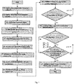
- Fig. 1 is a flow chart of a method of the present invention.
- a roll gap is in a over-lubricated critical state, and when the neutral angle is half the bite angle, the roll gap is in an under-lubricated critical state. Whether the roll gap is in the over-lubricated state or under-lubricated state, rolling mill vibration defects are caused.
- the tension system in the rolling process directly affects the lubrication state of each machine frame during the rolling process.
- the present invention starts from a tension system, optimizes a distribution of the tension system of the cold tandem rolling mill, realizes a coordinated control of a tension of each machine frame to ensure the best overall lubrication state of the cold tandem rolling mill and lubrication state of the individual machine frame, so that the rolling mill vibration defects can be controlled, and the surface quality of the finished strip steel of the cold tandem rolling mill and the stability of the rolling process can be improved.
- a tension system optimization method for suppressing vibration of a cold tandem rolling mill includes the following steps.
- the T 0 i y and T 1 i y are values of T 0 i and T 1 i when the F(X) value calculated in the S14 is minimum.
- the T 0 i y and T 1 i y are the T 0 i and T 1 i when the F(X) value calculated in the S14 is minimum.
- the T 0 i y and T 1 i y are the T 0 i and T 1 i when the F(X) value calculated in the S14 is minimum.
- the present invention can be further popularized to other similar cold tandem rolling mills domestically, for optimization of the tension system for suppressing the vibration of the rolling mill during the high-speed rolling process of the cold tandem rolling mill, which has a broad prospect for popularization and application.
Landscapes
- Engineering & Computer Science (AREA)
- Mechanical Engineering (AREA)
- Control Of Metal Rolling (AREA)
- Metal Rolling (AREA)
Abstract
Description
- The present invention relates to the technical field of metallurgical steel rolling, and more particularly relates to a tension system optimization method for suppressing vibration of a cold tandem rolling mill.
- In recent years, with the rapid development of automobile manufacturing, large ships, aerospace, and food packaging industries, the market demand for strips is increasingly enhanced. At the same time, downstream users' demand for high-precision and high-quality products promotes the development of large-scale and high-speed strip production device. In consideration of the complexity of strip production technology and production process, rolling mill vibration is often caused by the change of rolling conditions in a high-speed strip rolling process. Once the rolling mill vibration occurs, alternating light and dark stripes will be formed on the surface of strip steel, which will affect the surface quality of the strip steel. More seriously, damage to the rolling device is caused to result in on-site shutdown for maintenance, which greatly reduces the production efficiency of the strip production enterprise. Therefore, how to effectively solve the vibration problem of the cold tandem rolling mill in the high-speed process is the focus and difficulty in on-site technical research.
- Patent
201410026171.1 - The purpose of the present invention is to provide a tension system optimization method for suppressing vibration of a cold tandem rolling mill. By optimizing the tension system in the cold tandem rolling process, the problem of vibration in the high-speed rolling process of the cold tandem rolling mill can be controlled and suppressed, which plays an important role in improving the strip surface quality and improving the production efficiency of a strip production enterprise, and also brings economic benefits to the rolling mill.
- A tension system optimization method for suppressing vibration of a cold tandem rolling mill, including the following steps.
- S1. acquiring device feature parameters of the cold tandem rolling mill, including: a radius Ri of a work roll of each machine frame, a surface linear speed vri of a roll of each machine frame, original roughness Ra ir0 of the work roll of each machine frame, a roughness attenuation coefficient BLi of the work roll, and rolling distance in kilometer Li of the work roll of each machine frame after exchange of the roll, wherein, i = 1,2,...,n, representing the ordinal number of machine frames of the cold tandem rolling mill, and n is the total number of the machine frames;
- S2. acquiring critical rolling process parameters of a strip, including: elastic modulus E of the strip, a Poisson's ratio v of a strip, a strip width B, an inlet thickness h 0i of the strip for each machine frame, an exit thickness h 1i of the strip for each machine frame, a deformation resistance K of the strip, a rolling force Pi of each machine frame, an inlet speed v 0i of the strip in front of each machine frame, an influence coefficient kc of emulsion concentration, a viscosity compression coefficient θ of a lubricant, and dynamic viscosity η 0 of the lubricant;
- S3. defining an upper threshold


- S4. giving an initial set value of a target tension system optimization function for suppressing vibration of the cold tandem rolling mill: F 0 = 1.0 × 10¹⁰ ;
wherein S1 to S4 are not restricted in sequence; - S5. setting initial tension systems T0i and T1i, T 0i+1=T 1 i, wherein the initial tension systems can be 0. In practice, 0.3 times the hot rolling deformation resistance value is generally used as the initial tension system, and the maximum values of T 0i and T 1i , are the maximum values allowed by the device. Optimal tension systems


- S6. calculating a bite angle αi of each machine frame, wherein a calculation formula is as follows:


- S7. calculating an oil film thickness ξi in a current tension system, wherein a calculation formula is as follows:

- S8. calculating, according to the relationship between a friction coefficient ui and the oil film thickness ξi , a friction coefficient between the work roll of each machine frame and the strip steel: ui =ai +bi ·e B
i ·ξi , wherein ai is a liquid friction coefficient of the ith machine frame, bi is a dry friction coefficient of the ith machine frame, and Bi is a friction factor attenuation index of the ith machine frame; - S9. calculating a neutral angle γi of each machine frame in the current tension system according to the rolling theory, and a calculation formula is as follows:

- S10. calculating a vibration determination index ψi of each machine frame in the current tension system, wherein

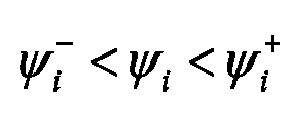
- S11. determining whether inequalities
- S12. calculating a target comprehensive tension system optimization function according to the following formula:


- S13. determining whether the inequality F(X)<F0 is established; if yes,

- S14. determining whether the tension systems T 0i and T 1i are beyond a range of a feasible domain; if yes, turning to step S15; otherwise, turning to step S5, wherein the range of the feasible domain is from 0 to the maximum values of T 0i and T 1i allowed by a device. That is, the present invention calculates the target function F(X) by continuously repeating the S5-S14 on T 0i and T 1i within the range of the feasible domain, and T 0i and T 1i when the F(X) value is minimum are the optimal inlet tension


- S15. outputting a set value of an optimal tension system: the optimal inlet tension


- According to an embodiment of the present invention, the value of krg is in a range of 0.09 to 0.15.
- According to an embodiment of the present invention, the value of Krs is in a range of 0.2 to 0.6.
- According to an embodiment of the present invention, the upper threshold


- The value range of the above values is a better range obtained based on experimental experience.
- The technical solution of a tension system optimization method for suppressing the vibration of the cold tandem rolling mill of the present invention is adopted, aiming at the vibration problem of the rolling mill during the high-speed rolling of the cold tandem rolling mill, the vibration determination index is defined to judge whether the rolling process of the cold tandem rolling mill is in a stable lubrication state without causing rolling mill vibration in the present invention, and based on this, the tension system optimization method for suppressing vibration of the cold tandem rolling mill is proposed, in combination with the device and process features of the cold tandem rolling mill, a suitable optimal value of the tension system is given, the high-speed and stable rolling process of the cold tandem rolling mill is ensured, the production efficiency of the strip production enterprise is improved, and the economic benefits of enterprises are improved; the present invention can be further popularized to other similar cold tandem rolling mills domestically, for optimization of the tension system for suppressing the vibration of the rolling mill during the high-speed rolling process of the cold tandem rolling mill, which has a broad prospect for popularization and application.
- In the present invention, the same reference numerals always indicate the same features, wherein:
Fig. 1 is a flow chart of a method of the present invention. - The technical solution of the present invention will be further described below in conjunction with the drawings and embodiments.
- During a rolling process of a cold tandem rolling mill, when a neutral angle is equal to a bite angle, a roll gap is in a over-lubricated critical state, and when the neutral angle is half the bite angle, the roll gap is in an under-lubricated critical state. Whether the roll gap is in the over-lubricated state or under-lubricated state, rolling mill vibration defects are caused. The tension system in the rolling process directly affects the lubrication state of each machine frame during the rolling process. Therefore, in order to control rolling mill vibration defects, the present invention starts from a tension system, optimizes a distribution of the tension system of the cold tandem rolling mill, realizes a coordinated control of a tension of each machine frame to ensure the best overall lubrication state of the cold tandem rolling mill and lubrication state of the individual machine frame, so that the rolling mill vibration defects can be controlled, and the surface quality of the finished strip steel of the cold tandem rolling mill and the stability of the rolling process can be improved.
- With reference to
Fig. 1 , a tension system optimization method for suppressing vibration of a cold tandem rolling mill includes the following steps. - S1. Device feature parameters of the cold tandem rolling mill are acquired, including: a radius Ri of a work roll of each machine frame, a surface linear speed vri of a roll of each machine frame, original roughness Ra ir0 of the work roll of each machine frame, a roughness attenuation coefficient BLi of the work roll, and rolling distance in kilometer Li of the work roll of each machine frame after exchange of the roll, wherein, i = 1,2,...,n, representing the ordinal number of machine frames of the cold tandem rolling mill, and n is the total number of the machine frames.
- S2. Critical rolling process parameters of a strip are acquired, including: elastic modulus E of the strip, a Poisson's ratio v of the strip, a strip width B, an inlet thickness h 0i of the strip for each machine frame, an exit thickness h 1i of the strip for each machine frame, a deformation resistance K of the strip, a rolling force Pi of each machine frame, an inlet speed v 0i of the strip in front of each machine frame, an influence coefficient kc of emulsion concentration, a viscosity compression coefficient θ of a lubricant, and dynamic viscosity η 0 of the lubricant.
- S3. An upper threshold


- S4. An initial set value of a target tension system optimization function for suppressing vibration of a cold tandem rolling mill is given: F 0 =1.0 × 10¹⁰.
wherein the S1 to S4 are not restricted in sequence and in some cases, the S1 to S4 can be executed simultaneously; - S5. Initial tension systems T 0i and T 1i are set, wherein T 0i+1=T 1 i.
- S6. A bite angle αi of each machine frame is calculated, wherein a calculation formula is as follows:


- S7. An oil film thickness ξi in a current tension system is calculated, wherein a calculation formula is as follows:

- S8. According to the relationship between the friction coefficient ui and the oil film thickness ξi , a friction coefficient between the work roll of each machine frame and the strip steel is calculated: ui =ai +bi ·eB
i ·ξi , wherein ai is a liquid friction coefficient of the ith machine frame, bi is a dry friction coefficient of the ith machine frame, and Bi is a friction factor attenuation index of the ith machine frame. - S9. A neutral angle γi of each machine frame in the current tension system is calculated according to the rolling theory, and a calculation formula is as follows:

- S10. A vibration determination index ψi of each machine frame in the current tension system is calculated.
- S11. It is determined whether inequalities

- S12. A target comprehensive tension system optimization function is calculated according to the following formula:


- S13. It is determined whether an inequality F(X)<F0 is established; if yes,

- S14. It is determined whether the tension systems T 0i and T 1i are beyond a range of a feasible domain; if yes, turning to step S15; otherwise, turning to step S5; the range of the feasible domain is from 0 to a maximum value of T 0i and T 1i allowed by the device.
- S15. A set value of an optimal tension system is output: the optimal inlet tension


-
- S1. Device feature parameters of the cold tandem rolling mill are acquired, including: a radius Ri ={1#217.5;2#217.5;3#217.5;4#217.5;5#217.5}(mm) of a work roll of each machine frame (5 machine frames), a surface linear speed vri ={1#149.6;2#292.3;3#328.3;4#449.2;5#585.5}(m/min) of a roll of each machine frame (5 machine frames), original roughness Ra ir0 = {1#0.53;2#0.53;3#0.53;4#0.53;5#0.53}(µm) of the work roll of each machine frame (5 machine frames), a roughness attenuation coefficient BLi ={1#0.01;2#0.0.1;3#0.01;4#0.01;5#0.01} of the work roll of each machine frame (5 machine frames), and rolling distance in kilometer Li ={1#200;2#180;3#190;4#220;5#250}(km) of the work roll of each machine frame (5 machine frames) after exchange of the roll, wherein i=1,2,...,5, representing the ordinal number of machine frames of the cold tandem rolling mill, and in all embodiments of the present application, the number before "#" refers to i, that is, the ith machine frame, and the corresponding parameters are after "#".
- S2. Critical rolling process parameters of a strip are acquired, including: elastic modulus E = 206GPa of a strip, a Poisson's ratio v = 0.3 of the strip, a strip width B = 812mm, an inlet thickness h 0i ={1#2.1;2#1.17;3#0.65;4#0.4;5#0.27}(mm) of the strip for each machine frame (5 machine frames), an exit thickness h 1i = {1#1.17; 2 #0.65;3# 0.40; 4 # 0.27; 5 # 0.22} (mm) of the strip for each machine frame (5 machine frames), a deformation resistance K = 502MPa of the strip, a rolling force Pi ={1#507.9;2#505.4;3#499.8,4#489.8;5#487.2}(t) of each machine frame, an inlet speed v 0i ={1#147.6;2#288.2;3#323.3;4#442.0;5 #575.5}(m/min) of the strip in front of each machine frame (5 machine frames), an influence coefficient kc =0.9 of emulsion concentration, a viscosity compression coefficient θ=0.034m 2 / N of a lubricant, and dynamic viscosity η 0 = 5.4 of the lubricant.
- S3. An upper threshold


- S4. An initial set value of a depressing schedule target comprehensive optimization function for suppressing vibration of a cold tandem rolling mill is given: F 0 = 1.0 × 10¹⁰. S5. Initial tension systems

- S6. A bite angle αi of each machine frame is calculated, wherein a calculation formula is as follows:


- S7. An oil film thickness ξi , in a current tension system is calculated, wherein a calculation formula is as follows:

in the formula, krg represents a strength coefficient of the lubricant entrained by the longitudinal roughness of the work roll and a strip steel, and is in a range of 0.09 to 0.15, and Krs represents an impression rate, i.e., a ratio of transferring the surface roughness of the work roll to the strip steel, and is in a range of 0.2 to 0.6. - S8. According to the relationship between the friction coefficient ui and the oil film thickness ξi , a friction coefficient between the work roll of each machine frame and the strip steel is calculated: ui =ai +bi·eB
i ·ξi , ui ={1#0.124;2#0.089;3#0.078;4#0.047;5#0.042}, wherein ai is a liquid friction coefficient of the ith machine frame, ai ={1#0.0126;2#0.0129;3#0.0122;4#0.0130;5#0.0142}, bi is a dry friction coefficient of the ith machine frame, bi ={1#0.1416;2#0.1424;3#0.1450;4#0.1464;5#0.1520}, and Bi is a friction factor attenuation index of the ith machine frame, Bi ={1#-2.4;2#-2.51;3#-2.33;4#-2.64;5#-2.58}. - S9. A neutral angle γi of each machine frame in the current tension system is calculated according to the rolling theory, and a calculation formula is as follows:

- S10. A vibration determination index ψi ={1#0.625;2#0.6;3#0.6;4#0.6;5#0.7} of each machine frame in the current tension system is calculated according to

- S11. It is determined whether inequalities

- S12. A comprehensive optimization target function of the tension system is calculated:

in the formula,
- S13. It is determined whether inequality F(X)<F 0 is established; if yes,

- S14. It is determined whether the tension systems T 0i and T 1i , are beyond a range of a feasible domain; if yes, turning to step S15, that is, the S5-S14 are continuously repeated for all data of T 0i and T 1i in the range of the feasible domain, calculated F(X) values are compared, and T 0i and T 1i when F(X) is minimum are selected.
- S15. A set value of an optimal tension system is output, wherein

- The


-
- S1. Device feature parameters of the cold tandem rolling mill are acquired, including: a radius Ri ={1#217.5;2#217.5;3#217.5;4#217.5;5#217.5}(mm) of a work roll of each machine frame (5 machine frames), a surface linear speed vri ={1#149.6;2#292.3;3#328.3;4#449.2;5#585.5}(m/min) of a roll of each machine frame (5 machine frames), original roughness Ra ir0 = {1#0.53;2#0.53;3#0.53;4#0.53;5#0.53} (µm) of the work roll of each machine frame (5 machine frames), a roughness attenuation coefficient BLi ={1#0.01;2#0.0.1;3#0.01;4#0.01;5#0.01} of the work roll of each machine frame (5 machine frames), and rolling distance in kilometer Li ={1#220;2#190;3#200;4#240;5#260}(km) of the work roll of each machine frame (5 machine frames) after exchange of the roll, wherein i=1,2,...,5, representing the ordinal number of machine frames of the cold tandem rolling mill.
- S2. Critical rolling process parameters of a strip are acquired, including: elastic modulus E = 210GPa of a strip, a Poisson's ratio v = 0.3 of the strip, a strip width B = 826mm, an inlet thickness h 0i ={1#2.2;2#1.27;3#0.75;4#0.5;5#0.37}(mm) of the strip for each machine frame (5 machine frames), an exit thickness h 1i ={1#1.27;2#0.75;3#0.50;4#0.37;5#0.32}(mm) of the strip for each machine frame (5 machine frames), a deformation resistance K = 510MPa of the strip, a rolling force Pi ={1#517.9;2#508.4;3#502.8;4#495.8;5#490.2}(t) of each machine frame, an inlet speed v 0i ={1#137.6;2#276.2;3#318.3;4#438.0;5#568.5}(m/min) of the strip in front of each machine frame (5 machine frames), an influence coefficient kc =0.9 of emulsion concentration, a viscosity compression coefficient θ=0.034m 2/N of a lubricant, and dynamic viscosity η 0 = 5.4 of the lubricant.
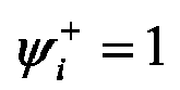
- S3. An upper threshold

- S4. An initial set value of a depressing schedule target comprehensive optimization function for suppressing vibration of the cold tandem rolling mill is given: F 0 = 1.0 ×10¹⁰.
- S5. Initial tension systems

- S6. A bite angle αi of each machine frame is calculated, wherein a calculation formula is as follows:


- S7. An oil film thickness ξi , in a current tension system is calculated, wherein a calculation formula is as follows:

in the formula, krg represents a coefficient of the strength of entrainment of lubricant by the longitudinal surface roughness of the work roll and the strip steel, and is in a range of 0.09 to 0.15, and Krs represents an impression rate, i.e., a ratio of transferring the surface roughness of the work roll to the strip steel, and is in a range of 0.2 to 0.6. - S8. According to the relationship between a friction coefficient ui and the oil film thickness ξi , a friction coefficient between the work roll of each machine frame and the strip steel is calculated: ui =ai +bi·.eB
i ·ξi , ui ={1#0.135;2#0.082;3#0.085;4#0.053;5 #0.047} , wherein ai is a liquid friction coefficient of the ith machine frame, ai ={1#0.0126;2#0.0129;3#0.0122;4#0.0130;5#0.0142}, bi is a dry friction coefficient of the ith machine frame, bi ={1#0.1416;2 #0.1424;3 #0.1450;4#0.1464;5 #0.1520}, and Bi is a friction factor attenuation index of the ith machine frame, Bi ={1#-2.4;2#-2.51;3#-2.33;4#-2.64;5#-2.58}. - S9. A neutral angle γi of each machine frame in the current tension system is calculated according to the rolling theory, and a calculation formula is as follows:

- S10. A vibration determination index ψi ={1#0.833;2#0.48;3#0.8;4#0.6;5#0.23} of each machine frame in the current tension system is calculated according to

- S11. It is determined whether inequalities

- S12. A target comprehensive tension system optimization function is calculated:

in the formula,
- S13. It is determined whether inequality F(X)<F 0 is established; if yes,

- S14. It is determined whether the tension systems T 0i and T 1i are beyond a range of a feasible domain; if yes, turning to step S15, that is, the S5-S14 are continuously repeated for all data of T 0i and T 1i , in the range of the feasible domain, calculated F(X) values are compared, and T 0i and T 1i when F(X) is minimum are selected.
- S15. A set value of an optimal tension system is output, wherein

- The


-
- S1. Device feature parameters of the cold tandem rolling mill are acquired, including: a radius Ri ={1#217.5;2#217.5;3#217.5;4#217.5;5#217.5}(mm) of a work roll of each machine frame (5 machine frames), a surface linear speed vri ={1#149.6;2#292.3;3#328.3;4#449.2;5#585.5}(m/min) of a roll of each machine frame (5 machine frames), original roughness Ra ir0 = {1#0.53;2#0.53;3#0.53;4#0.53;5#0.53}(µm) of the work roll of each machine frame (5 machine frames), a roughness attenuation coefficient BLi ={1#0.01;2#0.0.1;3#0.01;4#0.01;5#0.01} of the work roll of each machine frame (5 machine frames), and rolling distance in kilometer Li ={1#190;2#170;3#180;4#210;5#230}(km) of the work roll of each machine frame (5 machine frames) after exchange of the roll, wherein, i=1,2,...,5, representing the ordinal number of machine frames of the cold tandem rolling mill.
- S2. Critical rolling process parameters of a strip are acquired, including: elastic modulus E=201GPa of the strip, a Poisson's ratio v=0.3 of the strip, a strip width B=798mm, an inlet thickness h 0i ={1#2.0;2#1.01;3#0.55;4#0.35;5#0.25}(mm) of the strip for each machine frame (5 machine frames), an exit thickness h 1i ={1#1.01;2#0.55;3#0.35;4#0.25;5#0.19}(mm) of the strip for each machine frame (5 machine frames), a deformation resistance K=498MPa of the strip, a rolling force Pi ={1#526.9;2#525.4;3#502.3;4#496.5;5#493.4}(t) of each machine frame, an inlet speed v 0i ={1#159.5;2#296.3;3#335.4;4#448.0;5#586.3}(m/min) of the strip in front of each machine frame (5 machine frames), an influence coefficient kc =0.9 of emulsion concentration, a viscosity compression coefficient θ=0.034m 2/N of a lubricant, and dynamic viscosity η 0=5.4 of the lubricant.
- S3. An upper threshold


- S4. An initial set value F 0=1.0×10¹⁰ of a depressing schedule target comprehensive optimization function for suppressing vibration of the cold tandem rolling mill is given.
- S5. Initial tension systems

- S6. A bite angle αi of each machine frame is calculated, wherein a calculation formula is as follows:


- S7. An oil film thickness ξi in a current tension system is calculated, wherein a calculation formula is as follows:

in the formula, krg represents a coefficient of the strength of entrainment of lubricant by the longitudinal surface roughness of the work roll and the strip steel, and is in a range of 0.09 to 0.15, and Krs represents an impression rate, i.e., a ratio of transferring the surface roughness of the work roll to the strip steel, and is in a range of 0.2 to 0.6. - S8. According to the relationship between a friction coefficient ui and the oil film thickness ξi , a friction coefficient between the work roll of each machine frame and the strip steel is calculated: ui =ai +bi·eB
i ·ξi , ui ={1#0.115;2#0.082;3#0.071;4#0.042;5#0.039} , wherein ai is a liquid friction coefficient of the ith machine frame, ai ={1#0.0126;2#0.0129;3#0.0122;4#0.0130;5#0.0142}, bi is a dry friction coefficient of the ith machine frame, bi ={1#0.1416;2#0.1424;3#0.1450}-4#0.1464;5#0.1520}, and Bi is a friction factor attenuation index of the ith machine frame, Bi ={1#-2.4;2#-2.51;3#-2.33;4#-2.64;5#-2.58}. - S9. A neutral angle γi of each machine frame in the current tension system is calculated according to the rolling theory, and a calculation formula is as follows:

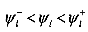
- S10. A vibration determination index ψi ={1#0.7;2#0.55;3#0.4;4#0.5;5#0.6} of each machine frame in the current tension system is calculated according to

- S11. It is determined whether inequalities
- S12. A target comprehensive tension system optimization function is calculated:

in the formula,
- S13. It is determined whether an inequality F(X)<F 0 is established; if yes,

- S14. It is determined whether tension systems T 0i , and T 1i , are beyond a range of a feasible domain; if yes, turning to step S15, that is, the S5-S14 are continuously repeated for all data of T 0i and T 1i in the range of the feasible domain, calculated F(X) values are compared, and T 0i and T 1i when the F(X) value is the minimum are selected.
- S15. A set value of an optimal tension system is output, wherein

- The


- In summary, the technical solution of the tension system optimization method for suppressing the vibration of the cold tandem rolling mill of the present invention is adopted, aiming at the vibration problem of the rolling mill during the high-speed rolling of the cold tandem rolling mill, the vibration determination index is defined to judge whether the rolling process of the cold tandem rolling mill is in a stable lubrication state without causing rolling mill vibration in the present invention, and based on this, a tension system optimization method for suppressing vibration of the cold tandem rolling mill is proposed, in combination with the device and process features of the cold tandem rolling mill, an objective is employed such that the vibration determination indexes of the machine frames are closest to the optimal value


Claims (4)
- A tension system optimization method for suppressing vibration of a cold tandem rolling mill, comprising the following steps:S1. acquiring device feature parameters of the cold tandem rolling mill, including: a radius Ri of a work roll of each machine frame, a surface linear speed vri of a roll of each machine frame, original roughness Ra ir0 of the work roll of each machine frame, a roughness attenuation coefficient BLi of the work roll, and rolling distance in kilometer Li of the work roll of each machine frame after exchange of the roll, wherein, i = 1,2,...,n, representing the ordinal number of machine frames of the cold tandem rolling mill, and n is the total number of the machine frames;S2. acquiring critical rolling process parameters of a strip, including: elastic modulus E of the strip, a Poisson's ratio v of the strip, a strip width B, an inlet thickness h 0i of the strip for each machine frame, an exit thickness h 1i of the strip for each machine frame, a deformation resistance K of the strip, a rolling force Pi of each machine frame, an inlet speed v 0i of the strip in front of each machine frame, an influence coefficient kc of emulsion concentration, a viscosity compression coefficient θ of a lubricant, and dynamic viscosity η 0 of the lubricant;S3. defining an upper threshold

 S4. giving an initial set value of a target tension system optimization function for suppressing vibration of the cold tandem rolling mill: F 0=1.0×10¹⁰ ;
wherein the S1 to S4 are not restricted in sequence;S5. setting initial tension systems T0i and T1i, wherein T 0i+1=T 1i ;S6. calculating a bite angle αi of each machine frame, wherein a calculation formula is as follows:
 S7. calculating an oil film thickness ξi in a current tension system, wherein a calculation formula is as follows:
 S8. calculating, according to the relationship between a friction coefficient ui and the oil film thickness ξi , the friction coefficient ui =ai +bi·eB
i ·ξi between the work roll of each machine frame and the strip steel, wherein ai is a liquid friction coefficient of the ith machine frame, bi is a dry friction coefficient of the ith machine frame, and Bi is a friction factor attenuation index of the ith machine frame;S9. calculating a neutral angle γi of each machine frame in the current tension system according to the rolling theory, and a calculation formula is as follows: S10. calculating a vibration determination index ψi of each machine frame in the current tension system, wherein
 S11. determining whether inequalities
 turning to step S12; otherwise, turning to step S5;S12. calculating a target comprehensive tension system optimization function according to the following formula:
 S13. determining whether an inequality F(X)<F 0 is established; if yes,
 S14. determining whether the tension systems T 0i and T 1i are beyond a range of a feasible domain; if yes, turning to step S15; otherwise, turning to step S5, wherein the range of the feasible domain is from 0 to maximum values of T 0i and T 1i allowed by a device; andS15. outputting a set value of an optimal tension system: the optimal inlet tension


- The tension system optimization method for suppressing vibration of the cold tandem rolling mill according to claim 1, wherein the value of krg is in a range of 0.09 to 0.15.
- The tension system optimization method for suppressing vibration of the tandem cold rolling mill according to claim 1, wherein the value of Krs is in the range of 0.2 to 0.6.
- The tension system optimization method for suppressing vibration of the tandem cold rolling mill according to claim 1, wherein the upper threshold


Applications Claiming Priority (2)
| Application Number | Priority Date | Filing Date | Title |
|---|---|---|---|
| CN201810831304.0A CN110756593B (en) | 2018-07-26 | 2018-07-26 | A tension system optimization method for suppressing vibration of cold tandem rolling mill |
| PCT/CN2019/097397 WO2020020192A1 (en) | 2018-07-26 | 2019-07-24 | Tension system optimization method for suppressing vibration of cold tandem rolling mill |
Publications (3)
| Publication Number | Publication Date |
|---|---|
| EP3827909A1 true EP3827909A1 (en) | 2021-06-02 |
| EP3827909A4 EP3827909A4 (en) | 2022-04-27 |
| EP3827909B1 EP3827909B1 (en) | 2023-05-31 |
Family
ID=69180774
Family Applications (1)
| Application Number | Title | Priority Date | Filing Date |
|---|---|---|---|
| EP19842345.1A Active EP3827909B1 (en) | 2018-07-26 | 2019-07-24 | Tension system optimization method for suppressing vibration of cold tandem rolling mill |
Country Status (5)
| Country | Link |
|---|---|
| US (1) | US11534807B2 (en) |
| EP (1) | EP3827909B1 (en) |
| JP (1) | JP7026289B2 (en) |
| CN (1) | CN110756593B (en) |
| WO (1) | WO2020020192A1 (en) |
Families Citing this family (12)
| Publication number | Priority date | Publication date | Assignee | Title |
|---|---|---|---|---|
| CN113434968B (en) * | 2020-03-23 | 2023-11-07 | 上海梅山钢铁股份有限公司 | A method for predicting cold rolling deformation resistance based on the chemical composition of steel plates |
| CN113449389B (en) * | 2020-03-24 | 2024-03-01 | 上海梅山钢铁股份有限公司 | A tension optimization setting method for hot-dip galvanizing units based on strip steel C warping control |
| CN112207136B (en) * | 2020-09-08 | 2021-07-16 | 燕山大学 | A strip constant tension looper control method based on rolling mill torsional vibration test analysis |
| CN113145648A (en) * | 2021-03-09 | 2021-07-23 | 宝钢湛江钢铁有限公司 | Optimization method for target reduction schedule by using vibration and slippage as prevention |
| CN113805484B (en) * | 2021-09-22 | 2023-05-19 | 燕山大学 | A rolling mill torsional vibration suppression control method based on adaptive dynamic surface |
| CN115156304B (en) * | 2022-06-14 | 2024-11-26 | 唐山钢铁集团有限责任公司 | A method for predicting the influence range of working roll movement on plate shape of four-high rolling mill |
| CN115156303B (en) * | 2022-06-14 | 2024-11-26 | 唐山钢铁集团有限责任公司 | A method for setting the amount of work roll shifting |
| CN115971252A (en) * | 2023-02-28 | 2023-04-18 | 宝钢湛江钢铁有限公司 | A 4-pass mode stand selection method for 5+1 type tandem cold rolling mill |
| CN116651944A (en) * | 2023-05-17 | 2023-08-29 | 马鞍山钢铁股份有限公司 | A method and system for reducing false alarms of strip breakage at entrance of UCM continuous rolling mill |
| CN116550767B (en) * | 2023-07-10 | 2023-09-22 | 太原理工大学 | A semi-automatic adjustment device that suppresses tension fluctuations during ultra-thin strip rolling |
| CN119747385A (en) * | 2025-02-06 | 2025-04-04 | 山西太钢不锈钢股份有限公司 | Rolling method for preventing S44626 brittle failure |
| CN120162988B (en) * | 2025-05-20 | 2025-07-18 | 东北大学 | A parameter optimization method for suppressing rolling mill vibration based on negative damping effect |
Family Cites Families (32)
| Publication number | Priority date | Publication date | Assignee | Title |
|---|---|---|---|---|
| DE3609623A1 (en) * | 1986-03-21 | 1987-10-01 | Jagenberg Ag | Device for measuring the web tension of a material web |
| JP2998550B2 (en) * | 1994-02-25 | 2000-01-11 | 日本鋼管株式会社 | Pass schedule determination method for reversible rolling mill |
| KR970010776B1 (en) * | 1994-09-23 | 1997-07-01 | 김만제 | Prediction Method of Hot Finish Rolling |
| JP3235449B2 (en) * | 1996-03-11 | 2001-12-04 | 日本鋼管株式会社 | High speed cold rolling method |
| IT1302766B1 (en) * | 1998-09-14 | 2000-09-29 | Danieli & C Ohg Sp | REDUCTION AND ELIMINATION PROCEDURE OF VIBRATIONS IN A LAMINATION CAGE AND RELATED DEVICE |
| JP3402217B2 (en) | 1998-09-18 | 2003-05-06 | 日本鋼管株式会社 | Cold rolling method |
| JP4402264B2 (en) * | 1999-08-11 | 2010-01-20 | 三菱重工業株式会社 | Rolling mill |
| US6361483B1 (en) * | 1999-10-22 | 2002-03-26 | Morrison Berkshire, Inc. | System for controlling vibration of a dynamic surface |
| JP2005297025A (en) | 2004-04-13 | 2005-10-27 | Kobe Steel Ltd | Predicting method and controlling method of chattering in tandem rolling equipment |
| FR2869819B1 (en) * | 2004-05-07 | 2006-08-04 | Vai Clecim Soc Par Actions Sim | METHOD AND DEVICE FOR DAMPING A ROLLER CAGE |
| CN100409242C (en) * | 2005-11-30 | 2008-08-06 | 宝山钢铁股份有限公司 | An optimization method aiming at scratch prevention in cold-strip continuous rolling mill |
| JP5383239B2 (en) | 2009-02-13 | 2014-01-08 | 株式会社神戸製鋼所 | Vibration prevention method in rolling mill |
| JP2010214453A (en) | 2009-03-18 | 2010-09-30 | Kobe Steel Ltd | Method of deciding tuning rate in cold rolling process and cold rolling method |
| CN102125936B (en) * | 2010-01-12 | 2012-12-12 | 宝山钢铁股份有限公司 | Method for controlling hot rolling coiling tension |
| CN101864517B (en) * | 2010-06-08 | 2011-12-07 | 首钢总公司 | Integrated optimization and setting method of tension in continuous annealing set furnace of continuous annealing set |
| JP5874372B2 (en) | 2011-12-16 | 2016-03-02 | Jfeスチール株式会社 | Cold rolling method for metal strip |
| ITMI20120476A1 (en) * | 2012-03-26 | 2013-09-27 | Danieli Off Mecc | VIBRATION DAMPING SYSTEM BY MEANS OF A HYDRAULIC IMPLEMENTATION SYSTEM |
| JP5961103B2 (en) * | 2012-12-11 | 2016-08-02 | 株式会社日立製作所 | Rolling control device, rolling control method, and rolling control program |
| DE102013106243C5 (en) * | 2013-06-14 | 2018-10-04 | Bwg Bergwerk- Und Walzwerk-Maschinenbau Gmbh | Method and device for stretch bending of metal strips |
| CN103302108B (en) * | 2013-07-02 | 2015-04-22 | 首钢总公司 | Optimal setting method for roll force of six-roller temper mill unit |
| CN104289528A (en) * | 2013-07-18 | 2015-01-21 | 上海宝钢钢材贸易有限公司 | Rolling tension control method of double-rack four-roller mill |
| CN103544340B (en) | 2013-09-26 | 2016-03-02 | 燕山大学 | The establishing method of concentration of emulsion used in five Stands Cold Tandem Mill group strip in razor-thin rollings |
| CN104785539B (en) * | 2014-01-21 | 2017-01-04 | 宝山钢铁股份有限公司 | A kind of method compensated for the tension optimization of roll-force regulation |
| WO2016014316A1 (en) * | 2014-07-25 | 2016-01-28 | Novelis Inc. | Rolling mill third octave chatter control by process damping |
| CN105522000B (en) | 2014-09-30 | 2018-06-01 | 宝山钢铁股份有限公司 | A kind of tandem mills vibration suppressing method |
| JP6296046B2 (en) * | 2015-02-17 | 2018-03-20 | Jfeスチール株式会社 | Vibration abnormality detection method and apparatus in cold rolling or temper rolling |
| CN104889175B (en) * | 2015-05-27 | 2017-04-26 | 首钢京唐钢铁联合有限责任公司 | Tension setting method for improving leveling stability and product surface quality |
| CN104942021B (en) * | 2015-06-26 | 2017-03-29 | 燕山大学 | A kind of plate shape On-Line Control Method for being suitable for continuous annealing process |
| DE102015223516A1 (en) * | 2015-09-23 | 2017-03-23 | Sms Group Gmbh | Roll stand, rolling mill and method for actively damping vibrations in a rolling stand |
| CN107790505B (en) | 2016-08-30 | 2019-06-18 | 上海梅山钢铁股份有限公司 | A kind of cold continuous rolling tension dynamic setting method of stable rolling |
| CN106311765B (en) * | 2016-10-11 | 2018-01-19 | 杭州电子科技大学 | High-speed rolling interfacial friction factor measurement apparatus and method |
| CN107695108B (en) | 2017-09-28 | 2019-03-01 | 北京首钢自动化信息技术有限公司 | A kind of tensile stress dynamic compensation method improving rolling process stability |
-
2018
- 2018-07-26 CN CN201810831304.0A patent/CN110756593B/en active Active
-
2019
- 2019-07-24 EP EP19842345.1A patent/EP3827909B1/en active Active
- 2019-07-24 US US17/258,888 patent/US11534807B2/en active Active
- 2019-07-24 JP JP2021502440A patent/JP7026289B2/en active Active
- 2019-07-24 WO PCT/CN2019/097397 patent/WO2020020192A1/en not_active Ceased
Also Published As
| Publication number | Publication date |
|---|---|
| JP7026289B2 (en) | 2022-02-25 |
| EP3827909A4 (en) | 2022-04-27 |
| WO2020020192A1 (en) | 2020-01-30 |
| CN110756593A (en) | 2020-02-07 |
| CN110756593B (en) | 2020-10-27 |
| US11534807B2 (en) | 2022-12-27 |
| JP2021532987A (en) | 2021-12-02 |
| US20220134399A1 (en) | 2022-05-05 |
| EP3827909B1 (en) | 2023-05-31 |
Similar Documents
| Publication | Publication Date | Title |
|---|---|---|
| EP3827909B1 (en) | Tension system optimization method for suppressing vibration of cold tandem rolling mill | |
| EP3804871B1 (en) | Emulsion flow optimization method for suppressing vibration of continuous cold rolling mill | |
| EP3815804B1 (en) | Method of emulsion concentration optimization for cold continuous rolling mill set | |
| CN106391725B (en) | One kind is suitable for cold-rolled process draught pressure and changes forecasting procedure with mill speed | |
| CN109550791B (en) | Tension system optimization method of cold continuous rolling unit with cavity opening prevention and control as target | |
| CN106909723A (en) | Cold-rolled process emulsifies flow quantity and mill speed relation curve Optimal Setting method | |
| CN103586286B (en) | Rolling schedule comprehensive optimization method for cold continuous rolling unit taking scratch prevention as objective | |
| CN105312321A (en) | Method for optimizing technological lubrication system of cold continuous rolling unit | |
| CN104785538B (en) | Reduction schedule optimization method for rolling ultrathin strip steel by cold continuous rolling set | |
| CN103611732A (en) | Optimization method of technological lubrication system taking galling prevention as objective for tandem cold mill | |
| CN110639958B (en) | Optimization method of original roll roughness for tandem cold rolling mill aiming at vibration suppression | |
| CN108723097B (en) | Optimization method of rolling parameters aiming at stable rolling under large deformation of DCR unit | |
| CN111036676A (en) | Production method of thin strip steel of cold continuous rolling mill | |
| CN111495980B (en) | Method for setting reduction schedule of cold continuous rolling unit with vibration suppression as target | |
| CN104289525B (en) | The cold rolling middle emulsion total flow set method of Stand Mill six-high cluster mill | |
| CN100409242C (en) | An optimization method aiming at scratch prevention in cold-strip continuous rolling mill | |
| CN112949028B (en) | Cold rolling mill slip judgment method based on limit static friction moment | |
| CN108787758A (en) | Rolling technological parameter optimal setting method under the conditions of secondary cold-rolling unit small deformation | |
| CN108460214A (en) | One kind is suitable for rolling stability check method under the conditions of secondary cold-rolling unit large deformation | |
| CN109590338A (en) | For reducing the parameter optimization technique of the rolling least amount of deformation between secondary cold-rolling | |
| CN120228107A (en) | A method, device, equipment and medium for optimizing rolling process of cold rolling mill | |
| CN120268810A (en) | Intelligent cold rolling control method for high-grade surface quality strip steel at high rolling speed | |
| CN105880299A (en) | Method for determining horizontal movement distance of working roller of cold rolling mill | |
| CN120382051A (en) | A method and production system for preventing and resolving double-sided corrugated plate defects in steel plates |
Legal Events
| Date | Code | Title | Description |
|---|---|---|---|
| STAA | Information on the status of an ep patent application or granted ep patent |
Free format text: STATUS: THE INTERNATIONAL PUBLICATION HAS BEEN MADE |
|
| PUAI | Public reference made under article 153(3) epc to a published international application that has entered the european phase |
Free format text: ORIGINAL CODE: 0009012 |
|
| STAA | Information on the status of an ep patent application or granted ep patent |
Free format text: STATUS: REQUEST FOR EXAMINATION WAS MADE |
|
| 17P | Request for examination filed |
Effective date: 20210226 |
|
| AK | Designated contracting states |
Kind code of ref document: A1 Designated state(s): AL AT BE BG CH CY CZ DE DK EE ES FI FR GB GR HR HU IE IS IT LI LT LU LV MC MK MT NL NO PL PT RO RS SE SI SK SM TR |
|
| DAV | Request for validation of the european patent (deleted) | ||
| DAX | Request for extension of the european patent (deleted) | ||
| A4 | Supplementary search report drawn up and despatched |
Effective date: 20220330 |
|
| RIC1 | Information provided on ipc code assigned before grant |
Ipc: B21B 37/48 20060101AFI20220324BHEP |
|
| 19U | Interruption of proceedings before grant |
Effective date: 20220225 |
|
| 19X | Information on stay/interruption of proceedings deleted |
Effective date: 20220520 |
|
| GRAP | Despatch of communication of intention to grant a patent |
Free format text: ORIGINAL CODE: EPIDOSNIGR1 |
|
| STAA | Information on the status of an ep patent application or granted ep patent |
Free format text: STATUS: GRANT OF PATENT IS INTENDED |
|
| INTG | Intention to grant announced |
Effective date: 20230203 |
|
| GRAS | Grant fee paid |
Free format text: ORIGINAL CODE: EPIDOSNIGR3 |
|
| GRAA | (expected) grant |
Free format text: ORIGINAL CODE: 0009210 |
|
| STAA | Information on the status of an ep patent application or granted ep patent |
Free format text: STATUS: THE PATENT HAS BEEN GRANTED |
|
| AK | Designated contracting states |
Kind code of ref document: B1 Designated state(s): AL AT BE BG CH CY CZ DE DK EE ES FI FR GB GR HR HU IE IS IT LI LT LU LV MC MK MT NL NO PL PT RO RS SE SI SK SM TR |
|
| REG | Reference to a national code |
Ref country code: GB Ref legal event code: FG4D Ref country code: CH Ref legal event code: EP |
|
| REG | Reference to a national code |
Ref country code: DE Ref legal event code: R096 Ref document number: 602019029627 Country of ref document: DE |
|
| P01 | Opt-out of the competence of the unified patent court (upc) registered |
Effective date: 20230503 |
|
| REG | Reference to a national code |
Ref country code: AT Ref legal event code: REF Ref document number: 1570641 Country of ref document: AT Kind code of ref document: T Effective date: 20230615 |
|
| REG | Reference to a national code |
Ref country code: IE Ref legal event code: FG4D |
|
| P02 | Opt-out of the competence of the unified patent court (upc) changed |
Effective date: 20230627 |
|
| REG | Reference to a national code |
Ref country code: LT Ref legal event code: MG9D |
|
| REG | Reference to a national code |
Ref country code: NL Ref legal event code: MP Effective date: 20230531 |
|
| REG | Reference to a national code |
Ref country code: AT Ref legal event code: MK05 Ref document number: 1570641 Country of ref document: AT Kind code of ref document: T Effective date: 20230531 |
|
| PG25 | Lapsed in a contracting state [announced via postgrant information from national office to epo] |
Ref country code: SE Free format text: LAPSE BECAUSE OF FAILURE TO SUBMIT A TRANSLATION OF THE DESCRIPTION OR TO PAY THE FEE WITHIN THE PRESCRIBED TIME-LIMIT Effective date: 20230531 Ref country code: NO Free format text: LAPSE BECAUSE OF FAILURE TO SUBMIT A TRANSLATION OF THE DESCRIPTION OR TO PAY THE FEE WITHIN THE PRESCRIBED TIME-LIMIT Effective date: 20230831 Ref country code: ES Free format text: LAPSE BECAUSE OF FAILURE TO SUBMIT A TRANSLATION OF THE DESCRIPTION OR TO PAY THE FEE WITHIN THE PRESCRIBED TIME-LIMIT Effective date: 20230531 Ref country code: AT Free format text: LAPSE BECAUSE OF FAILURE TO SUBMIT A TRANSLATION OF THE DESCRIPTION OR TO PAY THE FEE WITHIN THE PRESCRIBED TIME-LIMIT Effective date: 20230531 |
|
| PG25 | Lapsed in a contracting state [announced via postgrant information from national office to epo] |
Ref country code: RS Free format text: LAPSE BECAUSE OF FAILURE TO SUBMIT A TRANSLATION OF THE DESCRIPTION OR TO PAY THE FEE WITHIN THE PRESCRIBED TIME-LIMIT Effective date: 20230531 Ref country code: PL Free format text: LAPSE BECAUSE OF FAILURE TO SUBMIT A TRANSLATION OF THE DESCRIPTION OR TO PAY THE FEE WITHIN THE PRESCRIBED TIME-LIMIT Effective date: 20230531 Ref country code: NL Free format text: LAPSE BECAUSE OF FAILURE TO SUBMIT A TRANSLATION OF THE DESCRIPTION OR TO PAY THE FEE WITHIN THE PRESCRIBED TIME-LIMIT Effective date: 20230531 Ref country code: LV Free format text: LAPSE BECAUSE OF FAILURE TO SUBMIT A TRANSLATION OF THE DESCRIPTION OR TO PAY THE FEE WITHIN THE PRESCRIBED TIME-LIMIT Effective date: 20230531 Ref country code: LT Free format text: LAPSE BECAUSE OF FAILURE TO SUBMIT A TRANSLATION OF THE DESCRIPTION OR TO PAY THE FEE WITHIN THE PRESCRIBED TIME-LIMIT Effective date: 20230531 Ref country code: IS Free format text: LAPSE BECAUSE OF FAILURE TO SUBMIT A TRANSLATION OF THE DESCRIPTION OR TO PAY THE FEE WITHIN THE PRESCRIBED TIME-LIMIT Effective date: 20230930 Ref country code: HR Free format text: LAPSE BECAUSE OF FAILURE TO SUBMIT A TRANSLATION OF THE DESCRIPTION OR TO PAY THE FEE WITHIN THE PRESCRIBED TIME-LIMIT Effective date: 20230531 Ref country code: GR Free format text: LAPSE BECAUSE OF FAILURE TO SUBMIT A TRANSLATION OF THE DESCRIPTION OR TO PAY THE FEE WITHIN THE PRESCRIBED TIME-LIMIT Effective date: 20230901 |
|
| PG25 | Lapsed in a contracting state [announced via postgrant information from national office to epo] |
Ref country code: FI Free format text: LAPSE BECAUSE OF FAILURE TO SUBMIT A TRANSLATION OF THE DESCRIPTION OR TO PAY THE FEE WITHIN THE PRESCRIBED TIME-LIMIT Effective date: 20230531 |
|
| PG25 | Lapsed in a contracting state [announced via postgrant information from national office to epo] |
Ref country code: SK Free format text: LAPSE BECAUSE OF FAILURE TO SUBMIT A TRANSLATION OF THE DESCRIPTION OR TO PAY THE FEE WITHIN THE PRESCRIBED TIME-LIMIT Effective date: 20230531 |
|
| PG25 | Lapsed in a contracting state [announced via postgrant information from national office to epo] |
Ref country code: SM Free format text: LAPSE BECAUSE OF FAILURE TO SUBMIT A TRANSLATION OF THE DESCRIPTION OR TO PAY THE FEE WITHIN THE PRESCRIBED TIME-LIMIT Effective date: 20230531 Ref country code: SK Free format text: LAPSE BECAUSE OF FAILURE TO SUBMIT A TRANSLATION OF THE DESCRIPTION OR TO PAY THE FEE WITHIN THE PRESCRIBED TIME-LIMIT Effective date: 20230531 Ref country code: RO Free format text: LAPSE BECAUSE OF FAILURE TO SUBMIT A TRANSLATION OF THE DESCRIPTION OR TO PAY THE FEE WITHIN THE PRESCRIBED TIME-LIMIT Effective date: 20230531 Ref country code: PT Free format text: LAPSE BECAUSE OF FAILURE TO SUBMIT A TRANSLATION OF THE DESCRIPTION OR TO PAY THE FEE WITHIN THE PRESCRIBED TIME-LIMIT Effective date: 20231002 Ref country code: EE Free format text: LAPSE BECAUSE OF FAILURE TO SUBMIT A TRANSLATION OF THE DESCRIPTION OR TO PAY THE FEE WITHIN THE PRESCRIBED TIME-LIMIT Effective date: 20230531 Ref country code: DK Free format text: LAPSE BECAUSE OF FAILURE TO SUBMIT A TRANSLATION OF THE DESCRIPTION OR TO PAY THE FEE WITHIN THE PRESCRIBED TIME-LIMIT Effective date: 20230531 Ref country code: CZ Free format text: LAPSE BECAUSE OF FAILURE TO SUBMIT A TRANSLATION OF THE DESCRIPTION OR TO PAY THE FEE WITHIN THE PRESCRIBED TIME-LIMIT Effective date: 20230531 |
|
| PG25 | Lapsed in a contracting state [announced via postgrant information from national office to epo] |
Ref country code: MC Free format text: LAPSE BECAUSE OF FAILURE TO SUBMIT A TRANSLATION OF THE DESCRIPTION OR TO PAY THE FEE WITHIN THE PRESCRIBED TIME-LIMIT Effective date: 20230531 |
|
| PG25 | Lapsed in a contracting state [announced via postgrant information from national office to epo] |
Ref country code: MC Free format text: LAPSE BECAUSE OF FAILURE TO SUBMIT A TRANSLATION OF THE DESCRIPTION OR TO PAY THE FEE WITHIN THE PRESCRIBED TIME-LIMIT Effective date: 20230531 |
|
| REG | Reference to a national code |
Ref country code: CH Ref legal event code: PL |
|
| REG | Reference to a national code |
Ref country code: DE Ref legal event code: R097 Ref document number: 602019029627 Country of ref document: DE |
|
| REG | Reference to a national code |
Ref country code: BE Ref legal event code: MM Effective date: 20230731 |
|
| PG25 | Lapsed in a contracting state [announced via postgrant information from national office to epo] |
Ref country code: LU Free format text: LAPSE BECAUSE OF NON-PAYMENT OF DUE FEES Effective date: 20230724 |
|
| PG25 | Lapsed in a contracting state [announced via postgrant information from national office to epo] |
Ref country code: LU Free format text: LAPSE BECAUSE OF NON-PAYMENT OF DUE FEES Effective date: 20230724 |
|
| PLBE | No opposition filed within time limit |
Free format text: ORIGINAL CODE: 0009261 |
|
| STAA | Information on the status of an ep patent application or granted ep patent |
Free format text: STATUS: NO OPPOSITION FILED WITHIN TIME LIMIT |
|
| GBPC | Gb: european patent ceased through non-payment of renewal fee |
Effective date: 20230831 |
|
| REG | Reference to a national code |
Ref country code: IE Ref legal event code: MM4A |
|
| PG25 | Lapsed in a contracting state [announced via postgrant information from national office to epo] |
Ref country code: CH Free format text: LAPSE BECAUSE OF NON-PAYMENT OF DUE FEES Effective date: 20230731 |
|
| PG25 | Lapsed in a contracting state [announced via postgrant information from national office to epo] |
Ref country code: SI Free format text: LAPSE BECAUSE OF FAILURE TO SUBMIT A TRANSLATION OF THE DESCRIPTION OR TO PAY THE FEE WITHIN THE PRESCRIBED TIME-LIMIT Effective date: 20230531 |
|
| 26N | No opposition filed |
Effective date: 20240301 |
|
| PG25 | Lapsed in a contracting state [announced via postgrant information from national office to epo] |
Ref country code: SI Free format text: LAPSE BECAUSE OF FAILURE TO SUBMIT A TRANSLATION OF THE DESCRIPTION OR TO PAY THE FEE WITHIN THE PRESCRIBED TIME-LIMIT Effective date: 20230531 Ref country code: IT Free format text: LAPSE BECAUSE OF FAILURE TO SUBMIT A TRANSLATION OF THE DESCRIPTION OR TO PAY THE FEE WITHIN THE PRESCRIBED TIME-LIMIT Effective date: 20230531 Ref country code: FR Free format text: LAPSE BECAUSE OF NON-PAYMENT OF DUE FEES Effective date: 20230731 Ref country code: BE Free format text: LAPSE BECAUSE OF NON-PAYMENT OF DUE FEES Effective date: 20230731 |
|
| PG25 | Lapsed in a contracting state [announced via postgrant information from national office to epo] |
Ref country code: IE Free format text: LAPSE BECAUSE OF NON-PAYMENT OF DUE FEES Effective date: 20230724 |
|
| PG25 | Lapsed in a contracting state [announced via postgrant information from national office to epo] |
Ref country code: GB Free format text: LAPSE BECAUSE OF NON-PAYMENT OF DUE FEES Effective date: 20230831 |
|
| PG25 | Lapsed in a contracting state [announced via postgrant information from national office to epo] |
Ref country code: IE Free format text: LAPSE BECAUSE OF NON-PAYMENT OF DUE FEES Effective date: 20230724 Ref country code: GB Free format text: LAPSE BECAUSE OF NON-PAYMENT OF DUE FEES Effective date: 20230831 |
|
| PG25 | Lapsed in a contracting state [announced via postgrant information from national office to epo] |
Ref country code: BG Free format text: LAPSE BECAUSE OF FAILURE TO SUBMIT A TRANSLATION OF THE DESCRIPTION OR TO PAY THE FEE WITHIN THE PRESCRIBED TIME-LIMIT Effective date: 20230531 |
|
| PG25 | Lapsed in a contracting state [announced via postgrant information from national office to epo] |
Ref country code: BG Free format text: LAPSE BECAUSE OF FAILURE TO SUBMIT A TRANSLATION OF THE DESCRIPTION OR TO PAY THE FEE WITHIN THE PRESCRIBED TIME-LIMIT Effective date: 20230531 |
|
| PG25 | Lapsed in a contracting state [announced via postgrant information from national office to epo] |
Ref country code: CY Free format text: LAPSE BECAUSE OF FAILURE TO SUBMIT A TRANSLATION OF THE DESCRIPTION OR TO PAY THE FEE WITHIN THE PRESCRIBED TIME-LIMIT; INVALID AB INITIO Effective date: 20190724 |
|
| PG25 | Lapsed in a contracting state [announced via postgrant information from national office to epo] |
Ref country code: HU Free format text: LAPSE BECAUSE OF FAILURE TO SUBMIT A TRANSLATION OF THE DESCRIPTION OR TO PAY THE FEE WITHIN THE PRESCRIBED TIME-LIMIT; INVALID AB INITIO Effective date: 20190724 |
|
| PGFP | Annual fee paid to national office [announced via postgrant information from national office to epo] |
Ref country code: DE Payment date: 20250711 Year of fee payment: 7 |
|
| PG25 | Lapsed in a contracting state [announced via postgrant information from national office to epo] |
Ref country code: TR Free format text: LAPSE BECAUSE OF FAILURE TO SUBMIT A TRANSLATION OF THE DESCRIPTION OR TO PAY THE FEE WITHIN THE PRESCRIBED TIME-LIMIT Effective date: 20230531 |