EP3827736B1 - Optical coherence tomography device - Google Patents
Optical coherence tomography device Download PDFInfo
- Publication number
- EP3827736B1 EP3827736B1 EP18927293.3A EP18927293A EP3827736B1 EP 3827736 B1 EP3827736 B1 EP 3827736B1 EP 18927293 A EP18927293 A EP 18927293A EP 3827736 B1 EP3827736 B1 EP 3827736B1
- Authority
- EP
- European Patent Office
- Prior art keywords
- base
- drive mechanism
- connecting part
- hollow shaft
- movable base
- Prior art date
- Legal status (The legal status is an assumption and is not a legal conclusion. Google has not performed a legal analysis and makes no representation as to the accuracy of the status listed.)
- Active
Links
- 238000012014 optical coherence tomography Methods 0.000 title claims description 30
- 230000007246 mechanism Effects 0.000 claims description 76
- 238000012634 optical imaging Methods 0.000 claims description 49
- 238000001514 detection method Methods 0.000 claims description 46
- 230000001360 synchronised effect Effects 0.000 claims description 36
- 230000003287 optical effect Effects 0.000 claims description 31
- 239000000835 fiber Substances 0.000 claims description 29
- 238000003384 imaging method Methods 0.000 claims description 7
- 230000000903 blocking effect Effects 0.000 description 9
- 239000013307 optical fiber Substances 0.000 description 9
- 230000005540 biological transmission Effects 0.000 description 4
- 230000033001 locomotion Effects 0.000 description 4
- 238000010586 diagram Methods 0.000 description 3
- 238000000034 method Methods 0.000 description 2
- 230000001960 triggered effect Effects 0.000 description 2
- 238000005481 NMR spectroscopy Methods 0.000 description 1
- 238000004140 cleaning Methods 0.000 description 1
- 238000003759 clinical diagnosis Methods 0.000 description 1
- 238000004624 confocal microscopy Methods 0.000 description 1
- 230000002526 effect on cardiovascular system Effects 0.000 description 1
- 238000001839 endoscopy Methods 0.000 description 1
- 210000003238 esophagus Anatomy 0.000 description 1
- 238000000338 in vitro Methods 0.000 description 1
- 238000005305 interferometry Methods 0.000 description 1
- 230000004660 morphological change Effects 0.000 description 1
- 238000002610 neuroimaging Methods 0.000 description 1
- 210000000056 organ Anatomy 0.000 description 1
- 230000035515 penetration Effects 0.000 description 1
- 230000005855 radiation Effects 0.000 description 1
- 238000011897 real-time detection Methods 0.000 description 1
- 210000005000 reproductive tract Anatomy 0.000 description 1
- 210000002345 respiratory system Anatomy 0.000 description 1
- 238000004659 sterilization and disinfection Methods 0.000 description 1
- 238000003325 tomography Methods 0.000 description 1
- 238000002604 ultrasonography Methods 0.000 description 1
Images

Classifications
-
- G—PHYSICS
- G01—MEASURING; TESTING
- G01B—MEASURING LENGTH, THICKNESS OR SIMILAR LINEAR DIMENSIONS; MEASURING ANGLES; MEASURING AREAS; MEASURING IRREGULARITIES OF SURFACES OR CONTOURS
- G01B9/00—Measuring instruments characterised by the use of optical techniques
- G01B9/02—Interferometers
- G01B9/0209—Low-coherence interferometers
- G01B9/02091—Tomographic interferometers, e.g. based on optical coherence
-
- A—HUMAN NECESSITIES
- A61—MEDICAL OR VETERINARY SCIENCE; HYGIENE
- A61B—DIAGNOSIS; SURGERY; IDENTIFICATION
- A61B5/00—Measuring for diagnostic purposes; Identification of persons
- A61B5/0059—Measuring for diagnostic purposes; Identification of persons using light, e.g. diagnosis by transillumination, diascopy, fluorescence
- A61B5/0062—Arrangements for scanning
- A61B5/0066—Optical coherence imaging
-
- A—HUMAN NECESSITIES
- A61—MEDICAL OR VETERINARY SCIENCE; HYGIENE
- A61B—DIAGNOSIS; SURGERY; IDENTIFICATION
- A61B5/00—Measuring for diagnostic purposes; Identification of persons
- A61B5/0059—Measuring for diagnostic purposes; Identification of persons using light, e.g. diagnosis by transillumination, diascopy, fluorescence
- A61B5/0082—Measuring for diagnostic purposes; Identification of persons using light, e.g. diagnosis by transillumination, diascopy, fluorescence adapted for particular medical purposes
- A61B5/0084—Measuring for diagnostic purposes; Identification of persons using light, e.g. diagnosis by transillumination, diascopy, fluorescence adapted for particular medical purposes for introduction into the body, e.g. by catheters
-
- A—HUMAN NECESSITIES
- A61—MEDICAL OR VETERINARY SCIENCE; HYGIENE
- A61B—DIAGNOSIS; SURGERY; IDENTIFICATION
- A61B5/00—Measuring for diagnostic purposes; Identification of persons
- A61B5/68—Arrangements of detecting, measuring or recording means, e.g. sensors, in relation to patient
- A61B5/6846—Arrangements of detecting, measuring or recording means, e.g. sensors, in relation to patient specially adapted to be brought in contact with an internal body part, i.e. invasive
- A61B5/6847—Arrangements of detecting, measuring or recording means, e.g. sensors, in relation to patient specially adapted to be brought in contact with an internal body part, i.e. invasive mounted on an invasive device
- A61B5/6852—Catheters
-
- G—PHYSICS
- G01—MEASURING; TESTING
- G01B—MEASURING LENGTH, THICKNESS OR SIMILAR LINEAR DIMENSIONS; MEASURING ANGLES; MEASURING AREAS; MEASURING IRREGULARITIES OF SURFACES OR CONTOURS
- G01B9/00—Measuring instruments characterised by the use of optical techniques
- G01B9/02—Interferometers
- G01B9/02049—Interferometers characterised by particular mechanical design details
- G01B9/0205—Interferometers characterised by particular mechanical design details of probe head
-
- G—PHYSICS
- G02—OPTICS
- G02B—OPTICAL ELEMENTS, SYSTEMS OR APPARATUS
- G02B6/00—Light guides; Structural details of arrangements comprising light guides and other optical elements, e.g. couplings
- G02B6/24—Coupling light guides
- G02B6/36—Mechanical coupling means
- G02B6/3604—Rotary joints allowing relative rotational movement between opposing fibre or fibre bundle ends
-
- A—HUMAN NECESSITIES
- A61—MEDICAL OR VETERINARY SCIENCE; HYGIENE
- A61B—DIAGNOSIS; SURGERY; IDENTIFICATION
- A61B2562/00—Details of sensors; Constructional details of sensor housings or probes; Accessories for sensors
- A61B2562/22—Arrangements of medical sensors with cables or leads; Connectors or couplings specifically adapted for medical sensors
- A61B2562/225—Connectors or couplings
- A61B2562/228—Sensors with optical connectors
-
- A—HUMAN NECESSITIES
- A61—MEDICAL OR VETERINARY SCIENCE; HYGIENE
- A61B—DIAGNOSIS; SURGERY; IDENTIFICATION
- A61B5/00—Measuring for diagnostic purposes; Identification of persons
- A61B5/0059—Measuring for diagnostic purposes; Identification of persons using light, e.g. diagnosis by transillumination, diascopy, fluorescence
- A61B5/0073—Measuring for diagnostic purposes; Identification of persons using light, e.g. diagnosis by transillumination, diascopy, fluorescence by tomography, i.e. reconstruction of 3D images from 2D projections
Definitions
- the present invention relates to an optical coherence tomography device.
- OCT Optical Coherence Tomography
- CT optical Coherence Tomography
- two- or three-dimension images of biological tissues are captured by detecting back-reflection or scattering signals of low-coherence light incident on different tissue types.
- OCT was first proposed by a research team from the Massachusetts Institute of Technology in 1991.
- traditional imaging techniques such as nuclear magnetic resonance, X-rays and ultrasound
- OCT has a higher resolution, reaching up to the micron level, and also there is no risk of radiation since OCT devices typically operate in the near-infrared range.
- OCT is regarded as non-radiative computerized tomography (CT), but has a resolution that is 100 times higher than that of CT.
- OCT Compared with optical confocal microscopy for in-vitro detection, OCT has a greater penetration depth and is thus capable of detecting micron-level morphological changes of biological tissues. Moreover, OCT systems are easy to miniaturize and make portable by virtue of optical fiber technology, and thus are capable of performing real-time detection on tissues of bodies. In recent years, OCT, as a new imaging technique, has advanced by leaps and bounds. Traditional OCT equipment is widely used in clinical diagnosis in the field of ophthalmology. Additionally, researchers are using OCT imaging methods in various applications such as skin, teeth, cardiovascular, esophagus and brain imaging in combination with optical fiber technology and endoscopy.
- the main body of an OCT device transmits the optical signal to a fiber optic rotary joint, which transmits the optical signal.
- an optical imaging catheter is connected to a drive unit of the main body and an optical path of the fiber optic rotary joint.
- the drive unit drives the optical imaging catheter to perform a 360° rotation scan about the main axis thereof to obtain a B-scan image.
- the optical imaging catheter should be disassembled for cleaning and disinfection. It is highly desirable to provide a method to connect and remove the optical catheter from the drive unit conveniently.
- JP2017093537A1 discloses an OCT device that does not cause a problem in a catheter sheath by the rotation of a flexible shaft even if the catheter sheath is bent when an optical fiber is moved in a tip direction while being rotated.
- the fiber optic rotary joint With reference to the positioning of the fiber optic rotary joint, the hollow shaft and the optical imaging catheter it discloses that the optic rotary joint and the optical imaging catheter are not aligned.
- the objective of the present invention is to provide an optical coherence tomography device, which is capable of connecting and removing the optical catheter from the drive unit conveniently either manually or automatically.
- the objective of the present invention is achieved by adopting the following technical solutions.
- An optical coherence tomography device includes:
- a clamping member and a third drive mechanism are arranged on the movable base.
- the clamping member is arranged under the second connecting part.
- the third drive mechanism is configured to drive the clamping member to move toward or away from the second connecting part along the height direction of the base. When the first connecting part and the second connecting part are connected, the clamping member moves toward the second connecting part to tightly clamp the first connecting part and the second connecting part.
- the third drive mechanism includes a first linear motor.
- the housing of the first linear motor is fixedly connected to the movable base.
- the clamping member is fixedly connected to a power output end of the first linear motor.
- the detection end of the base is provided with a first trigger switch.
- the first trigger switch is configured to transmit a first trigger signal to the third drive mechanism after the clamping member tightly clamps the first connecting part and the second connecting part.
- the first drive mechanism includes a synchronous motor, a synchronous belt and two synchronous wheels.
- the housing of the synchronous motor is fixedly connected to the movable base, and a rotating shaft of the synchronous motor is fixedly connected to one of the synchronous wheels.
- the other synchronous wheel is sleeved on the outside of the hollow shaft and fixedly connected to the hollow shaft.
- the two ends of the synchronous belt are synchronously wound around the two synchronous wheels.
- the second drive mechanism includes a leadscrew motor, a leadscrew, a nut, and a guide mechanism.
- the housing of the leadscrew motor is fixedly connected to the base.
- the leadscrew extends along the length direction of the base and is synchronously connected to a rotor of the leadscrew motor.
- the nut is sleeved on the outside of the leadscrew and is in a thread-fit with the leadscrew.
- the nut is fixedly connected to the bottom end of the movable base, and is guided by the guide mechanism to move along the direction in which the leadscrew extends.
- the detection end of the base is provided with a stop block and a fourth drive mechanism.
- the stop block is movably mounted at the detection end.
- the fourth drive mechanism is configured to drive the stop block to move toward or away from the connecting end.
- the stop block is configured to block the end surface of the connecting end after moving toward the connecting end.
- the fourth drive mechanism includes a second linear motor.
- the housing of the second linear motor is fixedly connected to the base.
- the stop block is fixedly connected to a power output end of the second linear motor.
- the detection end of the base is provided with a second trigger switch.
- the second trigger switch is configured to transmit a second trigger signal to the fourth drive mechanism when the stop block blocks the end surface of the connecting end.
- a third trigger switch is arranged on the hollow shaft.
- the third trigger switch is configured to transmit a third trigger signal to the first drive mechanism after the hollow shaft rotates an angle A.
- the movable base moves toward the detection end to connect the second connecting part of the hollow shaft on the movable base to the first connecting part of the optical imaging catheter, so that the optical imaging catheter is synchronously coupled with the hollow shaft.
- the optical imaging catheter is either manually or automatically connected to or disconnected from the optical path of the optical fiber of the fiber optic rotary joint on the movable base very conveniently.
- the hollow shaft is driven to rotate by the first drive mechanism to drive the optical imaging catheter to rotate to capture an image of a single section of a lumen.
- the second drive mechanism drives the movable base to reciprocate to drive the optical imaging catheter to reciprocate, so that the optical imaging catheter is capable of scanning the whole section of the lumen to capture a stereoscopic 3D image.
- an optical coherence tomography device includes the base 10, the movable base 20, and a second drive mechanism.
- One end of the base 10 is provided with a detection end, and the other end of the base 10 is provided with a mounting end.
- the optical imaging catheter 40 is pivotally connected to the detection end, and the optical imaging catheter 40 can move along the length direction of the base 10.
- the optical imaging catheter 40 is provided with an imaging end and the connecting end 41.
- the connecting end 41 is detachably connected to the detection end, and the connecting end 41 is provided with the first connecting part 411.
- the movable base 20 is mounted at the mounting end and can move toward or away from the detection end along the length direction of the base 10.
- the movable base 20 is provided with the fiber optic rotary joint 30, the hollow shaft 50 and a first drive mechanism.
- the fiber optic rotary joint 30 is configured to transmit optical signals.
- the fiber optic rotary joint 30 is set away from the detection end and is fixedly connected to the movable base 20, and the end of the fiber optic rotary joint 30 adjacent to the detection end extends into the hollow shaft 50.
- the hollow shaft 50 is pivotally connected to the movable base 20.
- the first drive mechanism is configured to drive the hollow shaft 50 to rotate.
- the end of the hollow shaft 50 adjacent to the detection end is provided with the second connecting part 51.
- the second connecting part 51 is configured to be connected to the first connecting part 411, so that the optical imaging catheter 40 is coupled with the hollow shaft 50 to connect the optical imaging catheter 40 to an optical path of the fiber optic rotary joint 30.
- the movable base 20 is driven by the second drive mechanism to move along the length direction of the base 10.
- the second drive mechanism drives the movable base 20 to move toward the detection end to connect the second connecting part 51 of the hollow shaft 50 on the movable base 20 to the first connecting part 411 of the optical imaging catheter 40, so that the optical imaging catheter 40 is synchronously coupled with the hollow shaft 50, and the optical imaging catheter 40 is automatically or manually connected to or disconnected from the optical path of the optical fiber of the fiber optic rotary joint 30 on the movable base 20.
- the imaging end of the connected optical imaging catheter 40 is applied to the inside of a lumen for detection.
- the main body of the device is turned on to transmit an optical signal to the fiber optic rotary joint 30, and the optical signal is transmitted to the optical imaging catheter 40 through the fiber optic rotary joint 30.
- the hollow shaft 50 is driven to rotate by the first drive mechanism, thereby driving the optical imaging catheter 40 to rotate, so that the optical imaging catheter 40 is capable of capturing an image of a single section of the lumen.
- the second drive mechanism drives the movable base 20 to reciprocate, thereby driving the optical imaging catheter 40 to reciprocate, so that the optical imaging catheter 40 is capable of scanning the whole section of the lumen to capture a stereoscopic 3D image.
- the fiber optic rotary joint 30, the hollow shaft 50 and the optical imaging catheter 40 are coaxially connected on the base 10 in the following manner.
- the movable base 20 is provided with two mounting holes that are coaxially formed, in which the fiber optic rotary joint 30 and the hollow shaft 50 are mounted.
- the detection end of the base 10 is provided with a mounting hole in which the optical imaging catheter 40 is mounted, and the mounting hole is coaxial with the two mounting holes to facilitate automatic connection.
- first connecting part 411 can be implemented by using a known connecting male terminal of an optical fiber connector in the prior art
- second connecting part 51 can be implemented by using a known connecting female terminal of the optical fiber connector in the prior art.
- the clamping member 61 and a third drive mechanism are arranged on the movable base 20.
- the clamping member 61 is arranged under the second connecting part 51.
- the third drive mechanism is configured to drive the clamping member 61 to move toward or away from the second connecting part 51 along the height direction of the base 10, that is, to drive the clamping member 61 to move up and down.
- the clamping member 61 moves toward the second connecting part 51 to tightly clamp the first connecting part 411 and the second connecting part 51.
- the third drive mechanism drives the clamping member 61 to move toward the second connecting part 51, so that the clamping member 61 securely clamps the connection portion between the first connecting part 411 and the second connecting part 51 to reinforce the connection structure thereof.
- the clamping member 61 is driven to move downward by the third drive mechanism.
- the clamping member 61 can be implemented by using a structure such as a clamping jaw in the prior art.
- the third drive mechanism includes the first linear motor 60.
- the housing of the first linear motor 60 is fixedly connected to the movable base 20.
- the clamping member 61 is fixedly connected to the power output end of the first linear motor 60, that is, the first linear motor 60 can drive the clamping member 61 to move up and down.
- the third drive mechanism has a simple driving structure and is convenient to use.
- the third drive mechanism can also be implemented by other linear motion output mechanisms such as a drive cylinder and a leadscrew transmission mechanism in the prior art.
- the detection end of the base 10 is provided with a first trigger switch.
- the first trigger switch is configured to transmit a first trigger signal to the third drive mechanism after the clamping member 61 tightly clamps the first connecting part 411 and the second connecting part 51. That is, after the clamping member 61 tightly clamps the first connecting part 411 and the second connecting part 51, the first trigger switch 62 is triggered to control the third drive mechanism to stop in time.
- the first trigger switch 62 is a grating sensor
- the clamping member 61 is provided with an optical path blocking plate. The clamping member 61 moves up and down, so that the optical path blocking plate can disconnect or connect the optical path of the grating sensor to control the third drive mechanism to start or stop.
- the first trigger switch can also be a contact switch in the prior art.
- the first drive mechanism includes the synchronous motor 80, a synchronous belt and two synchronous wheels 81.
- the housing of the synchronous motor 80 is fixedly connected to the movable base 20, and a rotating shaft of the synchronous motor 80 is fixedly connected to one of the synchronous wheels 81.
- the other synchronous wheel 81 is sleeved on the outside of the hollow shaft 50 and fixedly connected to the hollow shaft 50.
- the two ends of the synchronous belt are synchronously wound around the two synchronous wheels 81.
- the first drive mechanism can also be directly implemented by an electric motor, or implemented by a combination of an electric motor and a gear transmission structure.
- the second drive mechanism specifically includes a leadscrew motor, a leadscrew, a nut, and a guide mechanism.
- the housing of the leadscrew motor is fixedly connected to the base 10.
- the leadscrew extends along the length direction of the base 10 and is synchronously connected to a rotor of the leadscrew motor.
- the nut is sleeved on the outside of the leadscrew and is in a thread-fit with the leadscrew.
- the nut is fixedly connected to the bottom end of the movable base 20, and is guided by the guide mechanism to move along the direction in which the leadscrew extends.
- the leadscrew motor is started to rotate to drive the leadscrew to rotate, and the rotation of the leadscrew is transformed into a linear motion along the direction in which the leadscrew extends (that is, the length direction of the base 10) through the nut that is in a thread-fit with the leadscrew and the guidance of the guide mechanism, so as to drive the movable base 20 fixedly connected to the nut to move along the length direction of the base 10.
- the guide mechanism specifically includes a sliding rail fixedly connected to the base 10 and a sliding groove formed at the bottom end of the movable base 20, and the sliding rail is slidably embedded in the sliding groove.
- the fourth trigger switch 11 can be arranged on the base 10.
- the fourth trigger switch 11 is configured to transmit a signal to the second drive mechanism to control the movable base 20 to start or stop in time when the movable base 20 moves to the two ends of the base 10.
- the fourth trigger switch 11 can also adopt a grating sensor.
- An optical path blocking plate is arranged on the movable base 20. The movable base 20 moves back and forth until the optical path blocking plate is disconnected or connected to the optical path of the grating sensor to control the second drive mechanism to start or stop.
- the fourth trigger switch 11 can also be a contact switch in the prior art.
- the detection end of the base 10 is provided with the stop block 71 and a fourth drive mechanism.
- the stop block 71 is movably mounted at the detection end.
- the fourth drive mechanism is configured to drive the stop block 71 to move toward or away from the connecting end 41.
- the stop block 71 is configured to block the end surface of the connecting end 41 after moving toward the connecting end 41.
- the stop block 71 is driven to move upward by the fourth drive mechanism to block the end surface of the connecting end 41 of the optical imaging catheter 40, so that the movable base 20 moves away from the optical imaging catheter 40, and the movement of the optical imaging catheter 40 is stopped by the stop block 71, so that the second connecting part 51 is separate and disconnected from the first connecting part 411.
- the first connecting part 411 is separate from the second connecting part 51 manually.
- the fourth drive mechanism includes the second linear motor 70.
- the housing of the second linear motor 70 is fixedly connected to the base 10.
- the stop block 71 is fixedly connected to the power output end of the second linear motor 70. That is, the stop block 71 is driven by the second linear motor 70 to move up and down.
- the driving structure is simple and convenient to use.
- the fourth drive mechanism can also be implemented by other linear motion output mechanisms such as a drive cylinder and a leadscrew drive mechanism in the prior art.
- the detection end of the base 10 is provided with the second trigger switch 72.
- the second trigger switch 72 is configured to transmit a second trigger signal to the fourth drive mechanism when the stop block 71 blocks the end surface of the connecting end 41. That is, when the stop block 71 moves to the end surface of the connecting end 41, the second trigger switch 72 is triggered to control the fourth drive mechanism to stop in time.
- the second trigger switch 72 can also adopt a grating sensor, and an optical path blocking plate is arranged on the stop block 71. When the stop block 71 moves up and down, the optical path blocking plate can disconnect or connect the optical path of the grating sensor to control the fourth drive mechanism to start or stop.
- the second trigger switch 72 can also be a contact switch in the prior art.
- the third trigger switch 82 is arranged on the hollow shaft 50, and the third trigger switch 82 is configured to transmit a third trigger signal to the first drive mechanism after the hollow shaft 50 rotates an angle A.
- the third trigger switch 82 adopts a grating sensor, and an optical path blocking plate is sleeved on the hollow shaft 50.
- a notch is provided on the optical path blocking plate, and the position of the notch located in the optical path of the grating sensor (that is, the optical path is connected) serves as a zero position.
- the first drive mechanism is controlled to start, that is, the hollow shaft 50 starts to rotate at a position as the starting point for recording the 360° scan performed by the optical imaging catheter 40.
- the notch of the optical path blocking plate returns to the zero position, which is counted as the first 360° scan of the optical imaging catheter 40 at this time.
- the third trigger switch 82 can also be implemented by a contact switch in the prior art.
Landscapes
- Health & Medical Sciences (AREA)
- Life Sciences & Earth Sciences (AREA)
- Physics & Mathematics (AREA)
- General Physics & Mathematics (AREA)
- General Health & Medical Sciences (AREA)
- Biomedical Technology (AREA)
- Medical Informatics (AREA)
- Biophysics (AREA)
- Pathology (AREA)
- Engineering & Computer Science (AREA)
- Nuclear Medicine, Radiotherapy & Molecular Imaging (AREA)
- Heart & Thoracic Surgery (AREA)
- Radiology & Medical Imaging (AREA)
- Molecular Biology (AREA)
- Surgery (AREA)
- Animal Behavior & Ethology (AREA)
- Public Health (AREA)
- Veterinary Medicine (AREA)
- Optics & Photonics (AREA)
- Investigating Or Analysing Materials By Optical Means (AREA)
Description
- The present invention relates to an optical coherence tomography device.
- Optical Coherence Tomography (OCT) is an optical imaging technique based on the principle of low-coherence interferometry, in which two- or three-dimension images of biological tissues are captured by detecting back-reflection or scattering signals of low-coherence light incident on different tissue types. OCT was first proposed by a research team from the Massachusetts Institute of Technology in 1991. Compared with traditional imaging techniques such as nuclear magnetic resonance, X-rays and ultrasound, OCT has a higher resolution, reaching up to the micron level, and also there is no risk of radiation since OCT devices typically operate in the near-infrared range. Thus, OCT is regarded as non-radiative computerized tomography (CT), but has a resolution that is 100 times higher than that of CT. Compared with optical confocal microscopy for in-vitro detection, OCT has a greater penetration depth and is thus capable of detecting micron-level morphological changes of biological tissues. Moreover, OCT systems are easy to miniaturize and make portable by virtue of optical fiber technology, and thus are capable of performing real-time detection on tissues of bodies. In recent years, OCT, as a new imaging technique, has advanced by leaps and bounds. Traditional OCT equipment is widely used in clinical diagnosis in the field of ophthalmology. Additionally, researchers are using OCT imaging methods in various applications such as skin, teeth, cardiovascular, esophagus and brain imaging in combination with optical fiber technology and endoscopy.
- When OCT is used to detect a respiratory tract, a reproductive tract or other tubular organs, the main body of an OCT device transmits the optical signal to a fiber optic rotary joint, which transmits the optical signal. Then an optical imaging catheter is connected to a drive unit of the main body and an optical path of the fiber optic rotary joint. In this way, the drive unit drives the optical imaging catheter to perform a 360° rotation scan about the main axis thereof to obtain a B-scan image. When the exam is finished, the optical imaging catheter should be disassembled for cleaning and disinfection. It is highly desirable to provide a method to connect and remove the optical catheter from the drive unit conveniently.
-
JP2017093537A1 - In order to overcome the shortcomings of the prior art, the objective of the present invention is to provide an optical coherence tomography device, which is capable of connecting and removing the optical catheter from the drive unit conveniently either manually or automatically.
- The objective of the present invention is achieved by adopting the following technical solutions.
- An optical coherence tomography device includes:
- a base, wherein one end of the base is provided with a detection end, and the other end of the base is provided with a mounting end; an optical imaging catheter is pivotally connected to the detection end; the optical imaging catheter can move along the length direction of the base; the optical imaging catheter is provided with an imaging end and a connecting end, wherein the connecting end is detachably connected to the detection end, and the connecting end is provided with a first connecting part;
- a movable base, wherein the movable base is mounted at the mounting end of the base and can move toward or away from the detection end along the length direction of the base; the movable base is provided with a fiber optic rotary joint configured to transmit optical signals, a hollow shaft and a first drive mechanism; the fiber optic rotary joint is set away from the detection end and is fixedly connected to the movable base; the end of the fiber optic rotary joint adjacent to the detection end extends into the hollow shaft; the hollow shaft is pivotally connected to the movable base, and the end of the hollow shaft adjacent to the detection end is provided with a second connecting part; when the movable base moves toward the detection end, the second connecting part is configured to be connected to the first connecting part so that the optical imaging catheter is coupled with the hollow shaft and the optical imaging catheter is connected to an optical path of the fiber optic rotary joint; the first drive mechanism is configured to drive the hollow shaft to rotate; and
- a second drive mechanism, wherein the second drive mechanism is configured to drive the movable base to move along the length direction of the base, wherein
- the fiber optic rotary joint, the hollow shaft and the optical imaging catheter are coaxially connected on the base, the movable base is provided with two mounting holes that are coaxially formed, in which the fiber optic rotary joint and the hollow shaft are mounted, the detection end of the base is provided with a mounting hole in which the optical imaging catheter is mounted, and the mounting hole is coaxial with the two mounting holes.
- Further, a clamping member and a third drive mechanism are arranged on the movable base. The clamping member is arranged under the second connecting part. The third drive mechanism is configured to drive the clamping member to move toward or away from the second connecting part along the height direction of the base. When the first connecting part and the second connecting part are connected, the clamping member moves toward the second connecting part to tightly clamp the first connecting part and the second connecting part.
- Further, the third drive mechanism includes a first linear motor. The housing of the first linear motor is fixedly connected to the movable base. The clamping member is fixedly connected to a power output end of the first linear motor.
- Further, the detection end of the base is provided with a first trigger switch. The first trigger switch is configured to transmit a first trigger signal to the third drive mechanism after the clamping member tightly clamps the first connecting part and the second connecting part.
- Further, the first drive mechanism includes a synchronous motor, a synchronous belt and two synchronous wheels. The housing of the synchronous motor is fixedly connected to the movable base, and a rotating shaft of the synchronous motor is fixedly connected to one of the synchronous wheels. The other synchronous wheel is sleeved on the outside of the hollow shaft and fixedly connected to the hollow shaft. The two ends of the synchronous belt are synchronously wound around the two synchronous wheels.
- Further, the second drive mechanism includes a leadscrew motor, a leadscrew, a nut, and a guide mechanism. The housing of the leadscrew motor is fixedly connected to the base. The leadscrew extends along the length direction of the base and is synchronously connected to a rotor of the leadscrew motor. The nut is sleeved on the outside of the leadscrew and is in a thread-fit with the leadscrew. The nut is fixedly connected to the bottom end of the movable base, and is guided by the guide mechanism to move along the direction in which the leadscrew extends.
- Further, the detection end of the base is provided with a stop block and a fourth drive mechanism. The stop block is movably mounted at the detection end. The fourth drive mechanism is configured to drive the stop block to move toward or away from the connecting end. The stop block is configured to block the end surface of the connecting end after moving toward the connecting end.
- Further, the fourth drive mechanism includes a second linear motor. The housing of the second linear motor is fixedly connected to the base. The stop block is fixedly connected to a power output end of the second linear motor.
- Further, the detection end of the base is provided with a second trigger switch. The second trigger switch is configured to transmit a second trigger signal to the fourth drive mechanism when the stop block blocks the end surface of the connecting end.
- Further, a third trigger switch is arranged on the hollow shaft. The third trigger switch is configured to transmit a third trigger signal to the first drive mechanism after the hollow shaft rotates an angle A.
- Compared with the prior art, the present invention has the following advantages. The movable base moves toward the detection end to connect the second connecting part of the hollow shaft on the movable base to the first connecting part of the optical imaging catheter, so that the optical imaging catheter is synchronously coupled with the hollow shaft. Moreover, the optical imaging catheter is either manually or automatically connected to or disconnected from the optical path of the optical fiber of the fiber optic rotary joint on the movable base very conveniently. After that, the hollow shaft is driven to rotate by the first drive mechanism to drive the optical imaging catheter to rotate to capture an image of a single section of a lumen. On the other hand, the second drive mechanism drives the movable base to reciprocate to drive the optical imaging catheter to reciprocate, so that the optical imaging catheter is capable of scanning the whole section of the lumen to capture a stereoscopic 3D image.
-
-
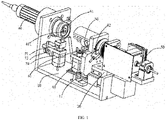
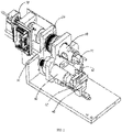
FIG. 1 is a schematic diagram of the structure of the present invention; -
FIG. 2 is a schematic diagram of the structure of the mounting end on the base of the present invention; and -
FIG. 3 is a schematic diagram of the structure of the detection end on the base of the present invention. - In the figures: 10, base; 11, fourth trigger switch; 20, movable base; 30, fiber optic rotary joint; 40, optical imaging catheter; 41, connecting end; 411, first connecting part; 50, hollow shaft; 51, second connecting part; 60, first linear motor; 61, clamping member; 62, first trigger switch; 70, second linear motor; 71, stop block; 72, second trigger switch; 80, synchronous motor; 81, synchronous wheel; and 82, third trigger switch.
- Hereinafter, the present invention will be further described with reference to the drawings and specific implementations. The invention is defined by appended claims 1-10.
- As shown in
FIGS. 1 ,2 and3 , an optical coherence tomography device includes thebase 10, themovable base 20, and a second drive mechanism. One end of thebase 10 is provided with a detection end, and the other end of thebase 10 is provided with a mounting end. Theoptical imaging catheter 40 is pivotally connected to the detection end, and theoptical imaging catheter 40 can move along the length direction of thebase 10. Specifically, theoptical imaging catheter 40 is provided with an imaging end and the connectingend 41. The connectingend 41 is detachably connected to the detection end, and the connectingend 41 is provided with the first connectingpart 411. - In addition, the
movable base 20 is mounted at the mounting end and can move toward or away from the detection end along the length direction of thebase 10. Themovable base 20 is provided with the fiber optic rotary joint 30, thehollow shaft 50 and a first drive mechanism. The fiber optic rotary joint 30 is configured to transmit optical signals. The fiber optic rotary joint 30 is set away from the detection end and is fixedly connected to themovable base 20, and the end of the fiber optic rotary joint 30 adjacent to the detection end extends into thehollow shaft 50. Thehollow shaft 50 is pivotally connected to themovable base 20. The first drive mechanism is configured to drive thehollow shaft 50 to rotate. The end of thehollow shaft 50 adjacent to the detection end is provided with the second connectingpart 51. When themovable base 20 moves toward the detection end, the second connectingpart 51 is configured to be connected to the first connectingpart 411, so that theoptical imaging catheter 40 is coupled with thehollow shaft 50 to connect theoptical imaging catheter 40 to an optical path of the fiber optic rotary joint 30. Specifically, themovable base 20 is driven by the second drive mechanism to move along the length direction of thebase 10. - On the basis of the above structure, when the optical coherence tomography device is in use, the second drive mechanism drives the
movable base 20 to move toward the detection end to connect the second connectingpart 51 of thehollow shaft 50 on themovable base 20 to the first connectingpart 411 of theoptical imaging catheter 40, so that theoptical imaging catheter 40 is synchronously coupled with thehollow shaft 50, and theoptical imaging catheter 40 is automatically or manually connected to or disconnected from the optical path of the optical fiber of the fiber optic rotary joint 30 on themovable base 20. The imaging end of the connectedoptical imaging catheter 40 is applied to the inside of a lumen for detection. The main body of the device is turned on to transmit an optical signal to the fiber optic rotary joint 30, and the optical signal is transmitted to theoptical imaging catheter 40 through the fiber optic rotary joint 30. After that, thehollow shaft 50 is driven to rotate by the first drive mechanism, thereby driving theoptical imaging catheter 40 to rotate, so that theoptical imaging catheter 40 is capable of capturing an image of a single section of the lumen. On the other hand, the second drive mechanism drives themovable base 20 to reciprocate, thereby driving theoptical imaging catheter 40 to reciprocate, so that theoptical imaging catheter 40 is capable of scanning the whole section of the lumen to capture a stereoscopic 3D image. - It should be noted that the fiber optic rotary joint 30, the
hollow shaft 50 and theoptical imaging catheter 40 are coaxially connected on the base 10 in the following manner. Themovable base 20 is provided with two mounting holes that are coaxially formed, in which the fiber optic rotary joint 30 and thehollow shaft 50 are mounted. Also, the detection end of thebase 10 is provided with a mounting hole in which theoptical imaging catheter 40 is mounted, and the mounting hole is coaxial with the two mounting holes to facilitate automatic connection. - In addition, the first connecting
part 411 can be implemented by using a known connecting male terminal of an optical fiber connector in the prior art, while the second connectingpart 51 can be implemented by using a known connecting female terminal of the optical fiber connector in the prior art. After themovable base 20 moves toward theoptical imaging catheter 40 that is adjacent to the detection end, the connecting male terminal of the optical fiber connector is plugged into the connecting female terminal of the optical fiber connector to connect the optical path. - Further, in the present embodiment, the clamping
member 61 and a third drive mechanism are arranged on themovable base 20. Specifically, the clampingmember 61 is arranged under the second connectingpart 51. The third drive mechanism is configured to drive the clampingmember 61 to move toward or away from the second connectingpart 51 along the height direction of thebase 10, that is, to drive the clampingmember 61 to move up and down. When the first connectingpart 411 and the second connectingpart 51 are connected, the clampingmember 61 moves toward the second connectingpart 51 to tightly clamp the first connectingpart 411 and the second connectingpart 51. In other words, after themovable base 20 moves toward the detection end, the first connectingpart 411 has been connected to the second connectingpart 51, and the third drive mechanism drives the clampingmember 61 to move toward the second connectingpart 51, so that the clampingmember 61 securely clamps the connection portion between the first connectingpart 411 and the second connectingpart 51 to reinforce the connection structure thereof. When the first connectingpart 411 and the second connectingpart 51 needs to be disconnected, the clampingmember 61 is driven to move downward by the third drive mechanism. Specifically, the clampingmember 61 can be implemented by using a structure such as a clamping jaw in the prior art. - Further, the third drive mechanism includes the first
linear motor 60. The housing of the firstlinear motor 60 is fixedly connected to themovable base 20. The clampingmember 61 is fixedly connected to the power output end of the firstlinear motor 60, that is, the firstlinear motor 60 can drive the clampingmember 61 to move up and down. The third drive mechanism has a simple driving structure and is convenient to use. Optionally, the third drive mechanism can also be implemented by other linear motion output mechanisms such as a drive cylinder and a leadscrew transmission mechanism in the prior art. - Further, the detection end of the
base 10 is provided with a first trigger switch. The first trigger switch is configured to transmit a first trigger signal to the third drive mechanism after the clampingmember 61 tightly clamps the first connectingpart 411 and the second connectingpart 51. That is, after the clampingmember 61 tightly clamps the first connectingpart 411 and the second connectingpart 51, thefirst trigger switch 62 is triggered to control the third drive mechanism to stop in time. In the present embodiment, thefirst trigger switch 62 is a grating sensor, and the clampingmember 61 is provided with an optical path blocking plate. The clampingmember 61 moves up and down, so that the optical path blocking plate can disconnect or connect the optical path of the grating sensor to control the third drive mechanism to start or stop. Optionally, the first trigger switch can also be a contact switch in the prior art. - Further, the first drive mechanism includes the
synchronous motor 80, a synchronous belt and twosynchronous wheels 81. The housing of thesynchronous motor 80 is fixedly connected to themovable base 20, and a rotating shaft of thesynchronous motor 80 is fixedly connected to one of thesynchronous wheels 81. The othersynchronous wheel 81 is sleeved on the outside of thehollow shaft 50 and fixedly connected to thehollow shaft 50. The two ends of the synchronous belt are synchronously wound around the twosynchronous wheels 81. When thehollow shaft 50 is driven to rotate, thesynchronous motor 80 is started to rotate to drive one of thesynchronous wheels 81 to rotate, and the othersynchronous wheel 81 fixedly connected to thehollow shaft 50 is also rotated through the transmission of the synchronous belt, so as to drive thehollow shaft 50 to rotate. In this way, the transmission structure is simple and stable. Optionally, the first drive mechanism can also be directly implemented by an electric motor, or implemented by a combination of an electric motor and a gear transmission structure. - Further, the second drive mechanism specifically includes a leadscrew motor, a leadscrew, a nut, and a guide mechanism. The housing of the leadscrew motor is fixedly connected to the
base 10. The leadscrew extends along the length direction of thebase 10 and is synchronously connected to a rotor of the leadscrew motor. The nut is sleeved on the outside of the leadscrew and is in a thread-fit with the leadscrew. The nut is fixedly connected to the bottom end of themovable base 20, and is guided by the guide mechanism to move along the direction in which the leadscrew extends. When themovable base 20 is driven to move along the length direction of thebase 10, the leadscrew motor is started to rotate to drive the leadscrew to rotate, and the rotation of the leadscrew is transformed into a linear motion along the direction in which the leadscrew extends (that is, the length direction of the base 10) through the nut that is in a thread-fit with the leadscrew and the guidance of the guide mechanism, so as to drive themovable base 20 fixedly connected to the nut to move along the length direction of thebase 10. The guide mechanism specifically includes a sliding rail fixedly connected to thebase 10 and a sliding groove formed at the bottom end of themovable base 20, and the sliding rail is slidably embedded in the sliding groove. - Optionally, the
fourth trigger switch 11 can be arranged on thebase 10. Thefourth trigger switch 11 is configured to transmit a signal to the second drive mechanism to control themovable base 20 to start or stop in time when themovable base 20 moves to the two ends of thebase 10. Thefourth trigger switch 11 can also adopt a grating sensor. An optical path blocking plate is arranged on themovable base 20. Themovable base 20 moves back and forth until the optical path blocking plate is disconnected or connected to the optical path of the grating sensor to control the second drive mechanism to start or stop. Optionally, thefourth trigger switch 11 can also be a contact switch in the prior art. - Further, the detection end of the
base 10 is provided with thestop block 71 and a fourth drive mechanism. Thestop block 71 is movably mounted at the detection end. The fourth drive mechanism is configured to drive thestop block 71 to move toward or away from the connectingend 41. Thestop block 71 is configured to block the end surface of the connectingend 41 after moving toward the connectingend 41. In this way, when the first connectingpart 411 needs to be disconnected from the second connectingpart 51, thestop block 71 is driven to move upward by the fourth drive mechanism to block the end surface of the connectingend 41 of theoptical imaging catheter 40, so that themovable base 20 moves away from theoptical imaging catheter 40, and the movement of theoptical imaging catheter 40 is stopped by thestop block 71, so that the second connectingpart 51 is separate and disconnected from the first connectingpart 411. Optionally, without thestop block 71 and the fourth drive mechanism, the first connectingpart 411 is separate from the second connectingpart 51 manually. - Further, the fourth drive mechanism includes the second
linear motor 70. The housing of the secondlinear motor 70 is fixedly connected to thebase 10. Thestop block 71 is fixedly connected to the power output end of the secondlinear motor 70. That is, thestop block 71 is driven by the secondlinear motor 70 to move up and down. The driving structure is simple and convenient to use. Optionally, the fourth drive mechanism can also be implemented by other linear motion output mechanisms such as a drive cylinder and a leadscrew drive mechanism in the prior art. - Specifically, the detection end of the
base 10 is provided with thesecond trigger switch 72. Thesecond trigger switch 72 is configured to transmit a second trigger signal to the fourth drive mechanism when thestop block 71 blocks the end surface of the connectingend 41. That is, when thestop block 71 moves to the end surface of the connectingend 41, thesecond trigger switch 72 is triggered to control the fourth drive mechanism to stop in time. In the present embodiment, thesecond trigger switch 72 can also adopt a grating sensor, and an optical path blocking plate is arranged on thestop block 71. When thestop block 71 moves up and down, the optical path blocking plate can disconnect or connect the optical path of the grating sensor to control the fourth drive mechanism to start or stop. Optionally, thesecond trigger switch 72 can also be a contact switch in the prior art. - Optionally, the third trigger switch 82 is arranged on the
hollow shaft 50, and the third trigger switch 82 is configured to transmit a third trigger signal to the first drive mechanism after thehollow shaft 50 rotates an angle A. In the present embodiment, the third trigger switch 82 adopts a grating sensor, and an optical path blocking plate is sleeved on thehollow shaft 50. A notch is provided on the optical path blocking plate, and the position of the notch located in the optical path of the grating sensor (that is, the optical path is connected) serves as a zero position. The first drive mechanism is controlled to start, that is, thehollow shaft 50 starts to rotate at a position as the starting point for recording the 360° scan performed by theoptical imaging catheter 40. After thehollow shaft 50 rotates an angle A (thehollow shaft 50 rotates 360° in the present embodiment), the notch of the optical path blocking plate returns to the zero position, which is counted as the first 360° scan of theoptical imaging catheter 40 at this time. Similarly, the third trigger switch 82 can also be implemented by a contact switch in the prior art. - The foregoing embodiments are only preferred embodiments of the present invention. The scope of the invention is defined by appended claims 1-10.
Claims (10)
- An optical coherence tomography device, comprising:a base (10) wherein a first end of the base is provided with a detection end, and a second end of the base is provided with a mounting end;an optical imaging catheter (40) is coaxially connected to the detection end;the optical imaging catheter is configured to move along a length direction of the base;the optical imaging catheter is provided with an imaging end and a connecting end (41), wherein the connecting end is removably connected to the detection end, and the connecting end is provided with a first connecting part (411);a movable base (20) mounted at the mounting end and the movable base is configured to move toward or away from the detection end along the length direction of the base;the movable base is provided with a fiber optic rotary joint (30) configured to transmit optical signals, a hollow shaft and a first drive mechanism;the fiber optic rotary joint is set away from the detection end, and the fiber optic rotary joint is fixedly connected to the movable base;an end of the fiber optic rotary joint is adjacent to the detection end, and the end of the fiber optic rotary joint extends into the hollow shaft;the hollow shaft is coaxially connected to the movable base, and an end of the hollow shaft adjacent to the detection end is provided with a second connecting part (51);when the movable base moves toward the detection end, the second connecting part is configured to be connected to the first connecting part, and the optical imaging catheter is coupled with the hollow shaft to connect the optical imaging catheter to an optical path of the fiber optic rotary joint;the first drive mechanism is configured to drive the hollow shaft to rotate; anda second drive mechanism configured to drive the movable base to move along the length direction of the basecharacterized in that the fiber optic rotary joint, the hollow shaft and the optical imaging catheter are coaxially connected on the base, the movable base is provided with two mounting holes that are coaxially formed, in which the fiber optic rotary joint and the hollow shaft are mounted, the detection end of the base is provided with a mounting hole in which the optical imaging catheter is mounted, and the mounting hole is coaxial with the two mounting holes.
- The optical coherence tomography device according to claim 1, whereina clamping member (61) and a third drive mechanism are arranged on the movable base, and the clamping member is arranged under the second connecting part;the third drive mechanism is configured to drive the clamping member to move toward or away from the second connecting part along a height direction of the base; andwhen the first connecting part and the second connecting part are connected, the clamping member is configured to move toward the second connecting part to tightly clamp the first connecting part and the second connecting part.
- The optical coherence tomography device according to claim 2, whereinThe third drive mechanism comprises a first linear motor (60), and a housing of the first linear motor is fixedly connected to the movable base; andthe clamping member is fixedly connected to a power output end of the first linear motor.
- The optical coherence tomography device according to claim 2, wherein
The detection end of the base is provided with a first trigger switch (62), and the first trigger switch is configured to transmit a first trigger signal to the third drive mechanism after the clamping member tightly clamps the first connecting part and the second connecting part. - The optical coherence tomography device according to claim 1, whereinthe first drive mechanism comprises a synchronous motor (80), a synchronous belt and two synchronous wheels (81);a housing of the synchronous motor is fixedly connected to the movable base;a rotating shaft of the synchronous motor is fixedly connected to a first synchronous wheel of the two synchronous wheels, and a second synchronous wheel of the two synchronous wheels is sleeved on an outside of the hollow shaft and the second synchronous wheel is fixedly connected to the hollow shaft; andtwo ends of the synchronous belt are synchronously wound around the two synchronous wheels.
- The optical coherence tomography device according to claim 1, whereinthe second drive mechanism comprises a leadscrew motor, a leadscrew, a nut, and a guide mechanism;a housing of the leadscrew motor is fixedly connected to the base;the leadscrew extends along the length direction of the base and the leadscrew is synchronously connected to a rotation shaft of the leadscrew motor;the nut is sleeved on an outside of the leadscrew and the nut is in a thread-fit with the leadscrew;the nut is fixedly connected to a bottom end of the movable base, andthe nut is configured to be guided by the guide mechanism to move along the length direction of the base.
- The optical coherence tomography device according to claim 1, whereinthe detection end of the base is provided with a stop block (71) and a fourth drive mechanism, and the stop block is movably mounted at the detection end;the fourth drive mechanism is configured to drive the stop block to move toward or away from the connecting end; andthe stop block is configured to block an end surface of the connecting end after moving toward the connecting end.
- The optical coherence tomography device according to claim 7, whereinthe fourth drive mechanism comprises a second linear motor (70), and a housing of the second linear motor is fixedly connected to the base; andthe stop block is fixedly connected to a power output end of the second linear motor.
- The optical coherence tomography device according to claim 7, wherein
The detection end of the base is provided with a second trigger switch (72), and the second trigger switch is configured to transmit a second trigger signal to the fourth drive mechanism when the stop block blocks the end surface of the connecting end. - The optical coherence tomography device according to claim 1, wherein
a third trigger switch (82) is arranged on the hollow shaft, and the third trigger switch is configured to transmit a third trigger signal to the first drive mechanism after the hollow shaft rotates an angle A.
Applications Claiming Priority (2)
| Application Number | Priority Date | Filing Date | Title |
|---|---|---|---|
| CN201810812476.3A CN109059753A (en) | 2018-07-23 | 2018-07-23 | A kind of optical interference fault imaging device |
| PCT/CN2018/097345 WO2020019281A1 (en) | 2018-07-23 | 2018-07-27 | Optical coherence tomography device |
Publications (3)
| Publication Number | Publication Date |
|---|---|
| EP3827736A1 EP3827736A1 (en) | 2021-06-02 |
| EP3827736A4 EP3827736A4 (en) | 2021-10-06 |
| EP3827736B1 true EP3827736B1 (en) | 2022-08-03 |
Family
ID=64836075
Family Applications (1)
| Application Number | Title | Priority Date | Filing Date |
|---|---|---|---|
| EP18927293.3A Active EP3827736B1 (en) | 2018-07-23 | 2018-07-27 | Optical coherence tomography device |
Country Status (4)
| Country | Link |
|---|---|
| US (1) | US11187520B2 (en) |
| EP (1) | EP3827736B1 (en) |
| CN (1) | CN109059753A (en) |
| WO (1) | WO2020019281A1 (en) |
Family Cites Families (13)
| Publication number | Priority date | Publication date | Assignee | Title |
|---|---|---|---|---|
| CH449057A (en) * | 1962-02-16 | 1967-12-31 | Turo Raivio Rolf | Optical method for setting a printing surface or parts thereof inside or outside a printing press and device for carrying out the method |
| FI96346C (en) * | 1993-10-27 | 1996-06-10 | Valto Ilomaeki | drill Rig |
| JP2002183946A (en) * | 2000-12-19 | 2002-06-28 | Kubota Corp | Gliding defect analyzer |
| EP2857876B1 (en) * | 2011-08-11 | 2020-07-08 | Ludwig-Maximilians-Universität München | Tunable VCSEL |
| US9370300B2 (en) * | 2012-04-24 | 2016-06-21 | Shenzhen Certainn Technology Co., Ltd. | Ophthalmic optical coherence tomography system and method for quick switching to realize anterior and posterior eye segments imaging |
| US9345398B2 (en) * | 2012-05-14 | 2016-05-24 | Avinger, Inc. | Atherectomy catheter drive assemblies |
| WO2014077871A2 (en) * | 2012-11-19 | 2014-05-22 | Lightlab Imaging, Inc. | Interface devices, systems and methods for multimodal probes |
| CN104111586A (en) * | 2013-06-27 | 2014-10-22 | 东莞市瑾耀精密设备有限公司 | Exposure machine based on CCD alignment system |
| CN204086473U (en) * | 2014-08-12 | 2015-01-07 | 深圳市朝阳光科技有限公司 | The correct detection device of full-automatic paster formula LED light splitting machine |
| JP2017093537A (en) * | 2015-11-19 | 2017-06-01 | 株式会社オプトハブ | Light interference tomographic image forming device |
| CN107796336B (en) * | 2016-09-06 | 2023-09-08 | 深圳市远东皓星科技有限公司 | Automatic optical detector |
| CN108095691A (en) * | 2017-12-18 | 2018-06-01 | 广州永士达医疗科技有限责任公司 | A kind of OCT probe rotating driving device for tube chamber road |
| CN208458666U (en) * | 2018-07-23 | 2019-02-01 | 深圳永士达医疗科技有限公司 | A kind of optical interference fault imaging device |
-
2018
- 2018-07-23 CN CN201810812476.3A patent/CN109059753A/en active Pending
- 2018-07-27 EP EP18927293.3A patent/EP3827736B1/en active Active
- 2018-07-27 US US17/280,914 patent/US11187520B2/en active Active
- 2018-07-27 WO PCT/CN2018/097345 patent/WO2020019281A1/en unknown
Also Published As
| Publication number | Publication date |
|---|---|
| US11187520B2 (en) | 2021-11-30 |
| EP3827736A1 (en) | 2021-06-02 |
| WO2020019281A1 (en) | 2020-01-30 |
| CN109059753A (en) | 2018-12-21 |
| US20210310790A1 (en) | 2021-10-07 |
| EP3827736A4 (en) | 2021-10-06 |
Similar Documents
| Publication | Publication Date | Title |
|---|---|---|
| JP4372351B2 (en) | Combined motor drive and longitudinal position automatic translator for ultrasound imaging systems | |
| US20120330102A1 (en) | Scanning Endoscopic Imaging Probes and Related Methods | |
| JP5485760B2 (en) | Optical coherence tomographic image forming apparatus and control method thereof | |
| CN113289201A (en) | Auxiliary execution device for vascular intervention operation | |
| CN111820917A (en) | Binocular vision blood sampling device and blood sampling robot with same | |
| JP2011072401A (en) | Optical probe and endoscope apparatus | |
| EP3827736B1 (en) | Optical coherence tomography device | |
| CN208458666U (en) | A kind of optical interference fault imaging device | |
| CN102100533A (en) | Integrated thermal-infrared scanning cystoscope system | |
| KR101582072B1 (en) | Injection device with ultrasonic probe | |
| JP2015181788A (en) | Tomographic apparatus and control method thereof | |
| CN102697455A (en) | Optical coherence tomography (OCT) electronic bronchoscope system | |
| KR20170110478A (en) | Pullback system for image processing | |
| CN115944396A (en) | Soft endoscope operation execution device | |
| CN202437069U (en) | Optical-coherence-tomography (OCT) hard cystoscope system | |
| CN102697469A (en) | Integral OCT (optical coherence tomography) hard anorectal endoscope system | |
| WO2019169675A1 (en) | Oct probe driving device and oct detection apparatus | |
| CN102697451A (en) | Optical coherence tomography (OCT) electronic bronchoscope system | |
| CN202426498U (en) | OCT (Optical Coherence Tomography) electronic bronchoscope system | |
| WO2018161383A1 (en) | Oct catheter withdrawal apparatus capable of achieving precise positioning | |
| CN202437073U (en) | Integrated OCT (Optical Coherence Tomography) hard anorectal mirror system | |
| CN215383970U (en) | Handheld OCT (optical coherence tomography) detection catheter withdrawing device | |
| CN202437064U (en) | Optical coherence tomography (OCT) electronic gastroscope system | |
| CN202437080U (en) | Integrated OCT (Optical Coherence Tomography) hard arthroscope system | |
| CN202426508U (en) | Integrated OCT (optical coherence tomography) rigid cholecyst endoscope system |
Legal Events
| Date | Code | Title | Description |
|---|---|---|---|
| STAA | Information on the status of an ep patent application or granted ep patent |
Free format text: STATUS: THE INTERNATIONAL PUBLICATION HAS BEEN MADE |
|
| PUAI | Public reference made under article 153(3) epc to a published international application that has entered the european phase |
Free format text: ORIGINAL CODE: 0009012 |
|
| STAA | Information on the status of an ep patent application or granted ep patent |
Free format text: STATUS: REQUEST FOR EXAMINATION WAS MADE |
|
| 17P | Request for examination filed |
Effective date: 20210329 |
|
| AK | Designated contracting states |
Kind code of ref document: A1 Designated state(s): AL AT BE BG CH CY CZ DE DK EE ES FI FR GB GR HR HU IE IS IT LI LT LU LV MC MK MT NL NO PL PT RO RS SE SI SK SM TR |
|
| A4 | Supplementary search report drawn up and despatched |
Effective date: 20210908 |
|
| RIC1 | Information provided on ipc code assigned before grant |
Ipc: G01B 9/02 20060101ALI20210902BHEP Ipc: A61B 5/00 20060101AFI20210902BHEP |
|
| DAV | Request for validation of the european patent (deleted) | ||
| DAX | Request for extension of the european patent (deleted) | ||
| REG | Reference to a national code |
Ref country code: DE Ref legal event code: R079 Ref document number: 602018038951 Country of ref document: DE Free format text: PREVIOUS MAIN CLASS: A61B0005000000 Ipc: G01B0009020910 |
|
| RIC1 | Information provided on ipc code assigned before grant |
Ipc: A61B 5/00 20060101ALI20220216BHEP Ipc: G01B 9/02 20060101ALI20220216BHEP Ipc: G01B 9/02091 20220101AFI20220216BHEP |
|
| GRAP | Despatch of communication of intention to grant a patent |
Free format text: ORIGINAL CODE: EPIDOSNIGR1 |
|
| STAA | Information on the status of an ep patent application or granted ep patent |
Free format text: STATUS: GRANT OF PATENT IS INTENDED |
|
| INTG | Intention to grant announced |
Effective date: 20220325 |
|
| GRAS | Grant fee paid |
Free format text: ORIGINAL CODE: EPIDOSNIGR3 |
|
| GRAA | (expected) grant |
Free format text: ORIGINAL CODE: 0009210 |
|
| STAA | Information on the status of an ep patent application or granted ep patent |
Free format text: STATUS: THE PATENT HAS BEEN GRANTED |
|
| AK | Designated contracting states |
Kind code of ref document: B1 Designated state(s): AL AT BE BG CH CY CZ DE DK EE ES FI FR GB GR HR HU IE IS IT LI LT LU LV MC MK MT NL NO PL PT RO RS SE SI SK SM TR |
|
| REG | Reference to a national code |
Ref country code: AT Ref legal event code: REF Ref document number: 1509066 Country of ref document: AT Kind code of ref document: T Effective date: 20220815 Ref country code: CH Ref legal event code: EP |
|
| REG | Reference to a national code |
Ref country code: DE Ref legal event code: R096 Ref document number: 602018038951 Country of ref document: DE |
|
| REG | Reference to a national code |
Ref country code: IE Ref legal event code: FG4D |
|
| REG | Reference to a national code |
Ref country code: LT Ref legal event code: MG9D |
|
| REG | Reference to a national code |
Ref country code: NL Ref legal event code: MP Effective date: 20220803 |
|
| PG25 | Lapsed in a contracting state [announced via postgrant information from national office to epo] |
Ref country code: SE Free format text: LAPSE BECAUSE OF FAILURE TO SUBMIT A TRANSLATION OF THE DESCRIPTION OR TO PAY THE FEE WITHIN THE PRESCRIBED TIME-LIMIT Effective date: 20220803 Ref country code: RS Free format text: LAPSE BECAUSE OF FAILURE TO SUBMIT A TRANSLATION OF THE DESCRIPTION OR TO PAY THE FEE WITHIN THE PRESCRIBED TIME-LIMIT Effective date: 20220803 Ref country code: PT Free format text: LAPSE BECAUSE OF FAILURE TO SUBMIT A TRANSLATION OF THE DESCRIPTION OR TO PAY THE FEE WITHIN THE PRESCRIBED TIME-LIMIT Effective date: 20221205 Ref country code: NO Free format text: LAPSE BECAUSE OF FAILURE TO SUBMIT A TRANSLATION OF THE DESCRIPTION OR TO PAY THE FEE WITHIN THE PRESCRIBED TIME-LIMIT Effective date: 20221103 Ref country code: NL Free format text: LAPSE BECAUSE OF FAILURE TO SUBMIT A TRANSLATION OF THE DESCRIPTION OR TO PAY THE FEE WITHIN THE PRESCRIBED TIME-LIMIT Effective date: 20220803 Ref country code: LV Free format text: LAPSE BECAUSE OF FAILURE TO SUBMIT A TRANSLATION OF THE DESCRIPTION OR TO PAY THE FEE WITHIN THE PRESCRIBED TIME-LIMIT Effective date: 20220803 Ref country code: LT Free format text: LAPSE BECAUSE OF FAILURE TO SUBMIT A TRANSLATION OF THE DESCRIPTION OR TO PAY THE FEE WITHIN THE PRESCRIBED TIME-LIMIT Effective date: 20220803 Ref country code: FI Free format text: LAPSE BECAUSE OF FAILURE TO SUBMIT A TRANSLATION OF THE DESCRIPTION OR TO PAY THE FEE WITHIN THE PRESCRIBED TIME-LIMIT Effective date: 20220803 Ref country code: ES Free format text: LAPSE BECAUSE OF FAILURE TO SUBMIT A TRANSLATION OF THE DESCRIPTION OR TO PAY THE FEE WITHIN THE PRESCRIBED TIME-LIMIT Effective date: 20220803 |
|
| REG | Reference to a national code |
Ref country code: AT Ref legal event code: MK05 Ref document number: 1509066 Country of ref document: AT Kind code of ref document: T Effective date: 20220803 |
|
| PG25 | Lapsed in a contracting state [announced via postgrant information from national office to epo] |
Ref country code: PL Free format text: LAPSE BECAUSE OF FAILURE TO SUBMIT A TRANSLATION OF THE DESCRIPTION OR TO PAY THE FEE WITHIN THE PRESCRIBED TIME-LIMIT Effective date: 20220803 Ref country code: IS Free format text: LAPSE BECAUSE OF FAILURE TO SUBMIT A TRANSLATION OF THE DESCRIPTION OR TO PAY THE FEE WITHIN THE PRESCRIBED TIME-LIMIT Effective date: 20221203 Ref country code: HR Free format text: LAPSE BECAUSE OF FAILURE TO SUBMIT A TRANSLATION OF THE DESCRIPTION OR TO PAY THE FEE WITHIN THE PRESCRIBED TIME-LIMIT Effective date: 20220803 Ref country code: GR Free format text: LAPSE BECAUSE OF FAILURE TO SUBMIT A TRANSLATION OF THE DESCRIPTION OR TO PAY THE FEE WITHIN THE PRESCRIBED TIME-LIMIT Effective date: 20221104 |
|
| PG25 | Lapsed in a contracting state [announced via postgrant information from national office to epo] |
Ref country code: SM Free format text: LAPSE BECAUSE OF FAILURE TO SUBMIT A TRANSLATION OF THE DESCRIPTION OR TO PAY THE FEE WITHIN THE PRESCRIBED TIME-LIMIT Effective date: 20220803 Ref country code: RO Free format text: LAPSE BECAUSE OF FAILURE TO SUBMIT A TRANSLATION OF THE DESCRIPTION OR TO PAY THE FEE WITHIN THE PRESCRIBED TIME-LIMIT Effective date: 20220803 Ref country code: DK Free format text: LAPSE BECAUSE OF FAILURE TO SUBMIT A TRANSLATION OF THE DESCRIPTION OR TO PAY THE FEE WITHIN THE PRESCRIBED TIME-LIMIT Effective date: 20220803 Ref country code: CZ Free format text: LAPSE BECAUSE OF FAILURE TO SUBMIT A TRANSLATION OF THE DESCRIPTION OR TO PAY THE FEE WITHIN THE PRESCRIBED TIME-LIMIT Effective date: 20220803 Ref country code: AT Free format text: LAPSE BECAUSE OF FAILURE TO SUBMIT A TRANSLATION OF THE DESCRIPTION OR TO PAY THE FEE WITHIN THE PRESCRIBED TIME-LIMIT Effective date: 20220803 |
|
| REG | Reference to a national code |
Ref country code: DE Ref legal event code: R081 Ref document number: 602018038951 Country of ref document: DE Owner name: SHENZHEN OCTIS MEDICAL TECHNOLOGY CO. LTD., SH, CN Free format text: FORMER OWNER: SHENZHEN WINSTAR MEDICAL TECHNOLOGY COMPANY LIMITED, SHENZHEN, GUANGDONG, CN |
|
| REG | Reference to a national code |
Ref country code: DE Ref legal event code: R097 Ref document number: 602018038951 Country of ref document: DE |
|
| REG | Reference to a national code |
Ref country code: GB Ref legal event code: 732E Free format text: REGISTERED BETWEEN 20230427 AND 20230503 |
|
| PG25 | Lapsed in a contracting state [announced via postgrant information from national office to epo] |
Ref country code: SK Free format text: LAPSE BECAUSE OF FAILURE TO SUBMIT A TRANSLATION OF THE DESCRIPTION OR TO PAY THE FEE WITHIN THE PRESCRIBED TIME-LIMIT Effective date: 20220803 Ref country code: EE Free format text: LAPSE BECAUSE OF FAILURE TO SUBMIT A TRANSLATION OF THE DESCRIPTION OR TO PAY THE FEE WITHIN THE PRESCRIBED TIME-LIMIT Effective date: 20220803 |
|
| PLBE | No opposition filed within time limit |
Free format text: ORIGINAL CODE: 0009261 |
|
| STAA | Information on the status of an ep patent application or granted ep patent |
Free format text: STATUS: NO OPPOSITION FILED WITHIN TIME LIMIT |
|
| PG25 | Lapsed in a contracting state [announced via postgrant information from national office to epo] |
Ref country code: AL Free format text: LAPSE BECAUSE OF FAILURE TO SUBMIT A TRANSLATION OF THE DESCRIPTION OR TO PAY THE FEE WITHIN THE PRESCRIBED TIME-LIMIT Effective date: 20220803 |
|
| 26N | No opposition filed |
Effective date: 20230504 |
|
| PGFP | Annual fee paid to national office [announced via postgrant information from national office to epo] |
Ref country code: FR Payment date: 20230627 Year of fee payment: 6 |
|
| PG25 | Lapsed in a contracting state [announced via postgrant information from national office to epo] |
Ref country code: SI Free format text: LAPSE BECAUSE OF FAILURE TO SUBMIT A TRANSLATION OF THE DESCRIPTION OR TO PAY THE FEE WITHIN THE PRESCRIBED TIME-LIMIT Effective date: 20220803 |
|
| PGFP | Annual fee paid to national office [announced via postgrant information from national office to epo] |
Ref country code: GB Payment date: 20230627 Year of fee payment: 6 |
|
| PGFP | Annual fee paid to national office [announced via postgrant information from national office to epo] |
Ref country code: DE Payment date: 20230720 Year of fee payment: 6 |
|
| PG25 | Lapsed in a contracting state [announced via postgrant information from national office to epo] |
Ref country code: MC Free format text: LAPSE BECAUSE OF FAILURE TO SUBMIT A TRANSLATION OF THE DESCRIPTION OR TO PAY THE FEE WITHIN THE PRESCRIBED TIME-LIMIT Effective date: 20220803 |
|
| PG25 | Lapsed in a contracting state [announced via postgrant information from national office to epo] |
Ref country code: MC Free format text: LAPSE BECAUSE OF FAILURE TO SUBMIT A TRANSLATION OF THE DESCRIPTION OR TO PAY THE FEE WITHIN THE PRESCRIBED TIME-LIMIT Effective date: 20220803 |
|
| REG | Reference to a national code |
Ref country code: CH Ref legal event code: PL |
|
| REG | Reference to a national code |
Ref country code: BE Ref legal event code: MM Effective date: 20230731 |
|
| PG25 | Lapsed in a contracting state [announced via postgrant information from national office to epo] |
Ref country code: LU Free format text: LAPSE BECAUSE OF NON-PAYMENT OF DUE FEES Effective date: 20230727 |
|
| PG25 | Lapsed in a contracting state [announced via postgrant information from national office to epo] |
Ref country code: LU Free format text: LAPSE BECAUSE OF NON-PAYMENT OF DUE FEES Effective date: 20230727 |
|
| REG | Reference to a national code |
Ref country code: IE Ref legal event code: MM4A |
|
| PG25 | Lapsed in a contracting state [announced via postgrant information from national office to epo] |
Ref country code: CH Free format text: LAPSE BECAUSE OF NON-PAYMENT OF DUE FEES Effective date: 20230731 |
|
| PG25 | Lapsed in a contracting state [announced via postgrant information from national office to epo] |
Ref country code: IT Free format text: LAPSE BECAUSE OF FAILURE TO SUBMIT A TRANSLATION OF THE DESCRIPTION OR TO PAY THE FEE WITHIN THE PRESCRIBED TIME-LIMIT Effective date: 20220803 Ref country code: BE Free format text: LAPSE BECAUSE OF NON-PAYMENT OF DUE FEES Effective date: 20230731 |
|
| PG25 | Lapsed in a contracting state [announced via postgrant information from national office to epo] |
Ref country code: IE Free format text: LAPSE BECAUSE OF NON-PAYMENT OF DUE FEES Effective date: 20230727 |
|
| PG25 | Lapsed in a contracting state [announced via postgrant information from national office to epo] |
Ref country code: IE Free format text: LAPSE BECAUSE OF NON-PAYMENT OF DUE FEES Effective date: 20230727 |